Embed Size (px)
Citation preview
PICOSECOND PULSE LABS P.O. BOX 44 BOULDER, CO 80306, USA TEL: 1.303.443.1249 FAX: 1.303.447.2236 WWW.PICOSECOND.COM
AN-3042d, Revision 1, 4/01 Page 1 of 9
Application Note AN-2d Copyright April, 2001
Comparison of Ultra-Fast Risetime
18 to 50 GHz Digital Sampling Oscilloscopes (updated to include new instruments introduced in 2000)
James R. Andrews, Ph.D.
PSPL Founder & IEEE Fellow
Starting in 1986, Picosecond Pulse Labs (PSPL) pub-lished an Application Note, AN-2, which was a compari-son of all commercially available, broadband sampling oscilloscopes with risetimes faster than 35 ps. Since then the oscilloscope manufacturers have introduced new models and discontinued old models. Revisions to AN-2 were published in 1989 as AN-2a, in 1994 as AN-2b, and in 1998 as AN-2c. In 2000, both Tektronix and Agilent introduced new 50 GHz, digital sampling oscilloscopes. This new AN-2d reviews the new TEK TDS-8000 and the Agilent 86100A oscilloscopes. The results of the previous AN-2s are still valid, and they should be referred to for older model oscilloscopes. The earlier versions of AN-2 are available from PSPL's Web site: www.picosecond.com. Tests performed on all oscillo-scopes included risetimes, picosecond domain transient responses, and nanosecond domain settling time re-sponses. This latest AN-2d now also includes 10 Gb/s eye diagram tests. OSCILLOSCOPES TESTED FOR AN-2d The high performance (>18 GHz bandwidth), digital sampling oscilloscope market is dominated by Tektronix and Agilent (formerly Hewlett-Packard). Both companies offer bandwidths up to 50 GHz. Both companies call their oscilloscopes also "communications signal analyzers". Agilent's newest oscilloscope is their model 86100A main frame. This main frame can hold up to two, dual-channel, electrical or optical sampling plug-ins. Agilent did not re-design their electrical sampling plug-ins. The 86100A main frame still uses the plug-ins from their previous 54750 oscilloscope and 83480 communication signal analyzer. Agilent has renumbered some of their previous plug-ins with new 861xx series numbers. The specific Agilent instrument tested by PSPL was the 86100A with electrical plug-ins, models 54753A (20/18/12 GHz, TDR) and 83484A (50/26 GHz). Tektronix's newest oscilloscope is their model TDS-8000 (or CSA-8000) main frame. This main frame can accom-modate up to four separate, dual-channel, electrical and two, single channel, optical plug-in sampling heads. Tek-tronix has totally redesigned their sampling heads. The
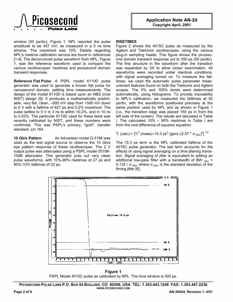
TDS-8000 does not support their earlier "SD" series plug-in sampling heads. Their new sampling heads now carry the model number designations of 80Exx and 80Cxx. The specific Tektronix instrument tested by PSPL was the model TDS-8000 with electrical plug-in module models 80E01 (50 GHz), 80E03 (20 GHz) and 80E04 (20 GHz TDR). Both Tektronix’s and Agilent's main frames are now basi-cally personal computers that include a set of electrical and/or optical connectors for high-speed electrical or op-tical measurements. These new oscilloscope designs use much faster microprocessors and run under a Win-dows operating system. These new instruments now op-erate like a personal computer, with operator inputs from either a touch screen, mouse, or keyboard, in addition to a few conventional knobs. They support all normal com-puter features, including external monitors, laser printers, modems, network connections, etc. PULSE GENERATORS For consistency between the various AN-2 application notes, we have continued to test the various oscillo-scopes with the same, or similar, pulse generators. For risetime and picosecond domain transient response tests, we have used 15 ps pulse generators. In the 1980s we used an HP-1106A tunnel diode pulser. PSPL's model TD1107 is a direct replacement for the discontin-ued HP-1106. Since 1994, we have used a PSPL model 4015 pulse generator. For nanosecond domain settling time tests, we have used a PSPL model 6110 reference flat pulse generator. Starting with this application note, we have included testing with a 10 Gb/s pulse pattern generator. 15 ps Pulser The PSPL model 4015C produces a –9 V, 15 ps falltime step pulse. For these tests the –9 V pulse was attenuated by 26 dB down to 450 mV, using PSPL model 5510K attenuators. The particular 4015C pulser and attenuators used for these tests were recently calibrated in the UK by the National Physical Lab (NPL). This was PSPL's primary, "gold", transfer standard, s/n 169. NPL reported the 10%-90% falltime of the attenu-ated pulse to be 15.3 ps, as measured in a 500 ps time
PICOSECOND PULSE LABS P.O. BOX 44 BOULDER, CO 80306, USA TEL: 1.303.443.1249 FAX: 1.303.447.2236 WWW.PICOSECOND.COM
Page 2 of 9 AN-3042d, Revision 1, 4/01
Application Note AN-2d Copyright April, 2001
window (50 ps/div), Figure 1. NPL reported the pulse amplitude to be 457 mV, as measured in a 5 ns time window. The overshoot was 10%. Details regarding NPL's risetime calibration service are found in references [1-4]. The deconvolved pulse waveform from NPL, Figure 1, was the reference waveform used to compare the various oscilloscopes' risetimes and picosecond domain transient responses. Reference Flat Pulse A PSPL model 6110D pulse generator was used to generate a known flat pulse for nanosecond domain, settling time measurements. The design of the model 6110D is based upon an NBS (now NIST) design [5]. It produces a mathematically predict-able, very flat, clean, –500 mV step from +500 mV down to 0 V with a falltime of 427 ps and 0.2% overshoot. The pulse settles to 0 V in 3 ns to within <0.2%, and in 10 ns to 0.02%. The particular 6110D used for these tests was recently calibrated by NIST, and these numbers were confirmed. This was PSPL's primary, "gold", transfer standard, s/n 164. 10 Gb/s Pattern An Advantest model D-3186 was used as the test signal source to observe the 10 Gb/s eye pattern response of these oscilloscopes. The 2 V output pulse was attenuated using a PSPL model 5510K-10dB attenuator. This generator puts out very clean pulse waveforms, with 10%-90% risetimes of 27 ps and 90%-10% falltimes of 22 ps.
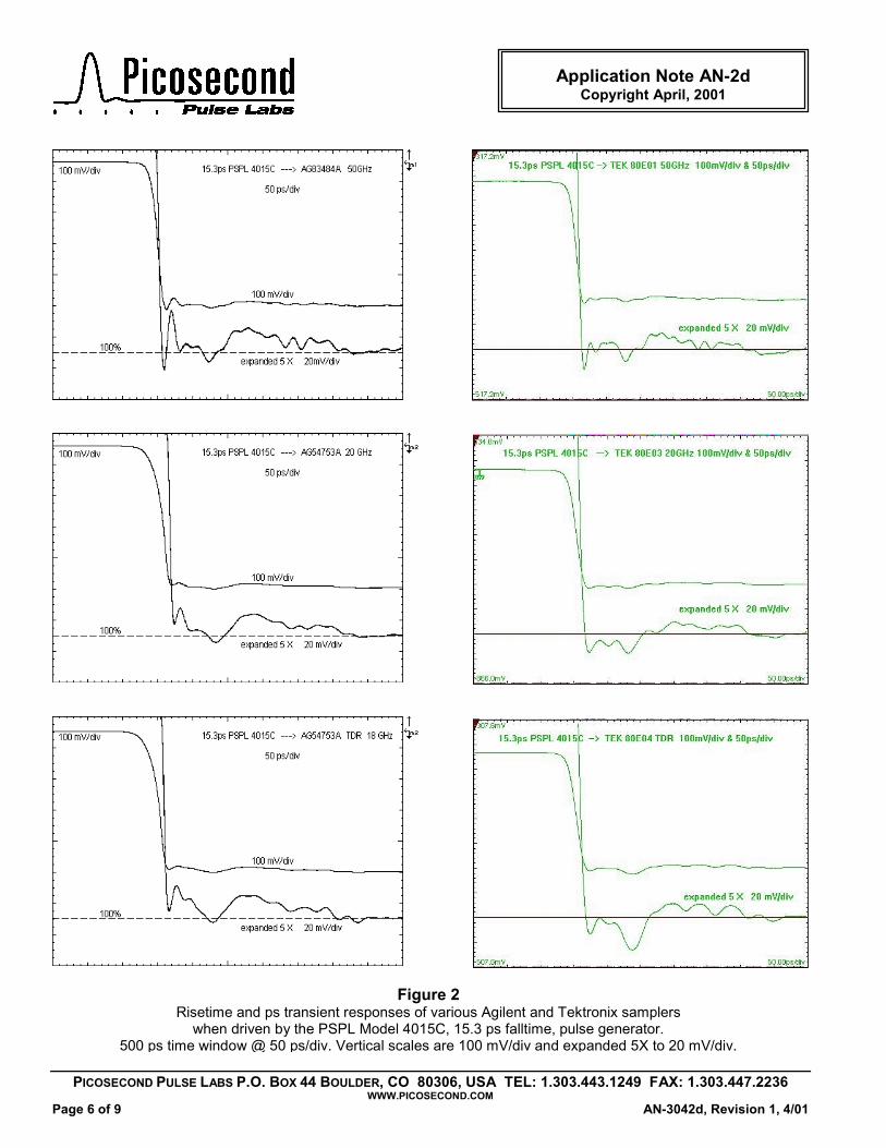
RISETIMES Figure 2 shows the 4015C pulse as measured by the Agilent and Tektronix oscilloscopes, using the various plug-in sampling heads. This figure shows the picosec-ond domain transient response out to 350 ps (50 ps/div). The fine structure in the waveform after the transition was expanded by 5X to allow closer examination. All waveforms were recorded under identical conditions, with signal averaging turned on. To measure the fall-times, we used the automatic pulse parameter meas-urement features found on both the Tektronix and Agilent scopes. The 0% and 100% levels were determined automatically, using histograms. To provide traceability to NPL's calibration, we measured the falltimes at 50 ps/div, with the waveforms positioned precisely at the same position used by NPL and as shown in Figure 1 (i.e., the transition edge was placed 150 ps in from the left side of the screen). The results are tabulated in Table I. The calculated 10% – 90% risetimes in Table I are from the root-difference-of-squares equation: Tr (calc) = [Tf
2 (meas)–15.3 ps2 (gen)–(2.57 * σ jitter)2] 1/2 The 15.3 ps term is the NPL calibrated falltime of the 4015C pulse generator. The last term accounts for the effects of using signal averaging on a time jittering transi-tion. Signal averaging of jitter is equivalent to adding an additional low-pass filter with a bandwidth of BW jitter = 0.132 / σ jitter, where σ jitter is the standard deviation of the timing jitter [6].
Figure 1 PSPL Model 4015C pulse as calibrated by NPL. The time window is 500 ps.
PICOSECOND PULSE LABS P.O. BOX 44 BOULDER, CO 80306, USA TEL: 1.303.443.1249 FAX: 1.303.447.2236 WWW.PICOSECOND.COM
AN-3042d, Revision 1, 4/01 Page 3 of 9
Application Note AN-2d Copyright April, 2001
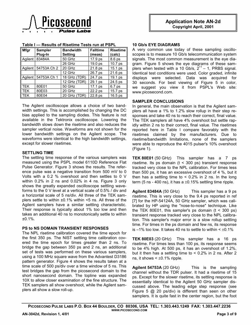
Table I — Results of Risetime Tests run at PSPL Mfgr Sampler
Plug-In Bandwidth Setting
Falltime (meas)
Risetime(calc)
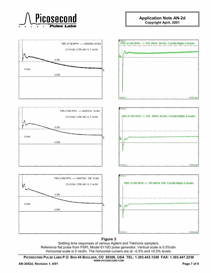
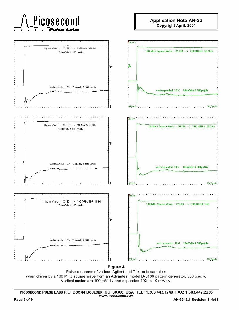
Agilent 83484A 50 GHz 17.9 ps 8.6 ps 26 GHz 19.0 ps 10.7 ps Agilent 54753A Ch 2 20 GHz 21.8 ps 15.1 ps 12 GHz 26.7 ps 21.6 ps Agilent 54753A Ch 1 18 GHz (TDR) 24.7 ps 19.1 ps 12 GHz (TDR) 29.1 ps 24.5 ps TEK 80E01 50 GHz 17.1 ps 6.7 ps TEK 80E03 20 GHz 22.2 ps 15.7 ps TEK 80E04 20 GHz (TDR) 22.8 ps 16.5 ps The Agilent oscilloscope allows a choice of two band-width settings. This is accomplished by changing the DC bias applied to the sampling diodes. This feature is not available in the Tektronix oscilloscope. Lowering the bandwidth slows down the risetime and also reduces the sampler vertical noise. Waveforms are not shown for the lower bandwidth settings on the Agilent scope. The waveforms were identical to the high bandwidth settings, except for slower risetimes. SETTLING TIME The settling time response of the various samplers was measured using the PSPL model 6110D Reference Flat Pulse Generator. Figure 3 shows the results. The refer-ence pulse was a negative transition from 500 mV to 0 Volts with a 0.2 % overshoot and then settles to 0 V within 0.2% in 2 ns and 0.02% in 4 ns. Figure 3 only shows the greatly expanded oscilloscope settling wave-forms to the 0 V level at a vertical scale of 0.5% / div and a horizontal scale of 5 ns/div. All three of the TEK sam-plers settle to within ±0.1% within <5 ns. All three of the Agilent samplers have a similar settling characteristic. Their response is typically about 1% too low and then takes an additional 40 ns to monotonically settle to within ±0.1%. PS to NS DOMAIN TRANSIENT RESPONSES The NPL risetime calibration covered the time epoch for the first 350 ps. The NIST settling time calibration cov-ered the time epoch for times greater than 2 ns. To bridge the gap between 350 ps and 2 ns, an additional set of tests was performed on these various samplers, using a 100 MHz square wave from the Advantest D3186 pattern generator. Figure 4 shows the results taken at a time scale of 500 ps/div over a time window of 5 ns. This test bridges the gap from the picosecond domain to the short nanosecond domain. The topline was expanded 10X to allow closer examination of the fine structure. The TEK samplers all show overshoot, while the Agilent sam-plers all show a slow roll-up.
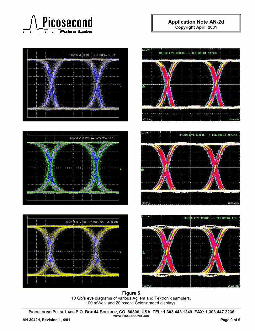
10 Gb/s EYE DIAGRAMS A very common use today of these sampling oscillo-scopes is to measure 10 Gb/s telecommunication system signals. The most common measurement is the eye dia-gram. Figure 5 shows the eye diagrams of these sam-plers when tested with a 10 Gb/s, 211 – 1, PRBS signal. Identical test conditions were used. Color graded, infinite displays were selected. Data was acquired for 30 seconds. For best viewing of Figure 5 in color, we suggest you view it from PSPL's Web site: www.picosecond.com. SAMPLER CONCLUSIONS In general, the main observation is that the Agilent sam-plers all have a 1% to 1.2% slow rollup in their step re-sponses and take 40 ns to reach their correct, final value. The TEK samplers all have 4% overshoot but settle rap-idly within 2 ns to their correct, final value. The risetimes reported here in Table I compare favorably with the risetimes claimed by the manufacturers. Due to risetime/bandwidth limitations, none of the samplers were able to reproduce the 4015 pulser's 10% overshoot (Figure 1). TEK 80E01 (50 GHz) This sampler has a 7 ps risetime. Its ps domain (t < 300 ps) transient response tracked very close to the NPL calibration. For times less than 500 ps, it has an excessive overshoot of 4 %, but it then has a settling time to < 0.2% in 2 ns. In the long term (5 ns - 400 ns), it has a ±0.15% settling time ripple. Agilent 83484A (50 GHz) This sampler has a 9 ps risetime. This is very close to the 9.4 ps reported in ref [7] for the HP-54124A, 50 GHz sampler, which was cali-brated by HP using the "nose-to-nose" technique. Like the TEK 80E01, this sampler's ps domain (t < 300 ps) transient response tracked very close to the NPL calibra-tion. This sampler's major error is a slow rollup settling time. For times in the ps domain and few ns, its response is –1% too low. It takes 40 ns to settle to within < ±0.1% TEK 80E03 (20 GHz) This sampler has a 16 ps risetime. For times less than 100 ps, its response seems to be 4% high. At 500 ps, it has an overshoot of 1.2%, but it then has a settling time to < 0.2% in 2 ns. After 2 ns, it shows < ±0.1% ripple. Agilent 54753A (20 GHz) This is the sampling channel without the TDR pulser. It had a risetime of 15 ps. Except for the slower risetime, its settling response is essentially identical to the Agilent 50 GHz sampler dis-cussed above. The leading edge step response (see Figure 5 @ 20 ps/div) is different than seen on other samplers. It is quite fast in the center region, but the foot
PICOSECOND PULSE LABS P.O. BOX 44 BOULDER, CO 80306, USA TEL: 1.303.443.1249 FAX: 1.303.447.2236 WWW.PICOSECOND.COM
Page 4 of 9 AN-3042d, Revision 1, 4/01
Application Note AN-2d Copyright April, 2001
on the leading edge rises slowly, and likewise there is then a slow roll-up toward the 100% level. This causes the 10 Gb/s eye diagram to have an almost circular ap-pearance. TEK 80E04 (TDR 20 GHz) This sampler has a 17 ps risetime. This sampler had the most noticeable defect in its ps domain response of all the samplers tested. This was a large +6.5% bump located 80 ps after the leading edge of the pulse. It is surmised that this bump is due to an internal reflection between the sampler and the TDR pulser circuitry. The 10 Gb/s eye diagram of this sampler was deemed unacceptable due to this reflection. This sampler would be acceptable for eye diagram testing at 2.5 Gb/s and lower, but not at 10 Gb/s. With the excep-tion of the +6.5% bump, the transient and settling time responses of this sampler were identical to the 80E03. Note: After observing the unacceptable 10 Gb/s eye diagram, PSPL has been in correspondence with Tek-tronix's sampler design engineers to call their attention to the problem. The Tektronix engineers have since in-formed PSPL that they are working on a solution to rem-edy this defect. Thus, this defect may not be present in future production 80E04 TDR samplers. Agilent 54753A (TDR 18 GHz) This sampler includes a built-in TDR pulser. It has a 19 ps risetime. Except for the slower risetime, its response is identical to the Agilent 20 GHz sampler discussed above. OTHER TESTS PSPL also performed several other tests on these oscil-loscopes. They included checking the time base calibra-tion, trigger jitter, input impedance, vertical noise, DC voltage calibration, and low frequency square wave re-sponse. In most cases the scopes performed far better than specified by the manufacturers. The digital time bases in both of these scopes were extremely accurate for all times from ps to ms. Even on the very fast 10 ps/div sweep, errors were typically less than 1 ps in 100 ps. For ns and µs sweeps, the accuracies were found to be better than 0.2%. Both scopes include two trigger cir-cuits: a direct DC-coupled trigger and a pre-scaler. Agilent's trigger is rated for operation from DC to 2.5 GHz direct and to 12 GHz with the pre-scaler. Tektronix's trig-ger is rated for operation from DC to 3 GHz direct and to 10 GHz with the pre-scaler. Table II lists the measured jitters under several test conditions. For the particular scopes tested, the Agilent triggered up to 2.5 GHz direct and 15 GHz with the prescaler, while the TEK triggered up to 5 GHz direct and 13 GHz with the prescaler. Tek-tronix's prescaler caused some "kick-out" from its input connector, which caused some distortion onto the signal under test. This "kick-out" was not observed on the Agilent scope.
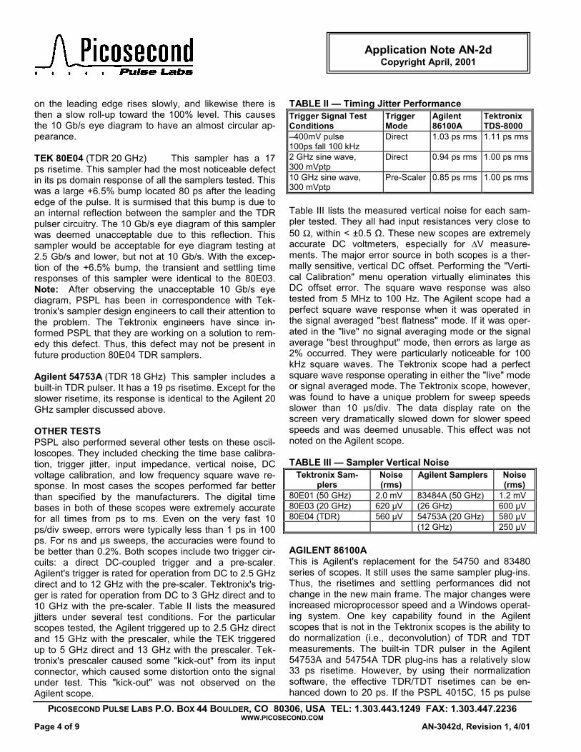
TABLE II — Timing Jitter Performance Trigger Signal Test Conditions
Trigger Mode
Agilent 86100A
Tektronix TDS-8000
–400mV pulse 100ps fall 100 kHz
Direct 1.03 ps rms 1.11 ps rms
2 GHz sine wave, 300 mVptp
Direct 0.94 ps rms 1.00 ps rms
10 GHz sine wave, 300 mVptp
Pre-Scaler 0.85 ps rms 1.00 ps rms
Table III lists the measured vertical noise for each sam-pler tested. They all had input resistances very close to 50 Ω, within < ±0.5 Ω. These new scopes are extremely accurate DC voltmeters, especially for ∆V measure-ments. The major error source in both scopes is a ther-mally sensitive, vertical DC offset. Performing the "Verti-cal Calibration" menu operation virtually eliminates this DC offset error. The square wave response was also tested from 5 MHz to 100 Hz. The Agilent scope had a perfect square wave response when it was operated in the signal averaged "best flatness" mode. If it was oper-ated in the "live" no signal averaging mode or the signal average "best throughput" mode, then errors as large as 2% occurred. They were particularly noticeable for 100 kHz square waves. The Tektronix scope had a perfect square wave response operating in either the "live" mode or signal averaged mode. The Tektronix scope, however, was found to have a unique problem for sweep speeds slower than 10 µs/div. The data display rate on the screen very dramatically slowed down for slower speed speeds and was deemed unusable. This effect was not noted on the Agilent scope. TABLE III — Sampler Vertical Noise
Tektronix Sam-plers
Noise (rms)
Agilent Samplers Noise (rms)
80E01 (50 GHz) 2.0 mV 83484A (50 GHz) 1.2 mV 80E03 (20 GHz) 620 µV (26 GHz) 600 µV 80E04 (TDR) 560 µV 54753A (20 GHz) 580 µV (12 GHz) 250 µV AGILENT 86100A This is Agilent's replacement for the 54750 and 83480 series of scopes. It still uses the same sampler plug-ins. Thus, the risetimes and settling performances did not change in the new main frame. The major changes were increased microprocessor speed and a Windows operat-ing system. One key capability found in the Agilent scopes that is not in the Tektronix scopes is the ability to do normalization (i.e., deconvolution) of TDR and TDT measurements. The built-in TDR pulser in the Agilent 54753A and 54754A TDR plug-ins has a relatively slow 33 ps risetime. However, by using their normalization software, the effective TDR/TDT risetimes can be en-hanced down to 20 ps. If the PSPL 4015C, 15 ps pulse
PICOSECOND PULSE LABS P.O. BOX 44 BOULDER, CO 80306, USA TEL: 1.303.443.1249 FAX: 1.303.447.2236 WWW.PICOSECOND.COM
AN-3042d, Revision 1, 4/01 Page 5 of 9
Application Note AN-2d Copyright April, 2001
generator is used with this scope, then normalized TDR and TDT risetimes down to 10 ps can be obtained. De-tails are found in PSPL's application note, AN-5c [8 & 9]. An objection to Agilent's present TDR software (version A.02.01) is that it does not allow the use of the auto-mated pulse parameter measurements when in the TDR/TDT mode, except for rise/falltime. TEKTRONIX TDS-8000 This is Tektronix's replacement for the 11,800 series os-cilloscopes. Like the Agilent 86100A, the TDS-8000 uses a faster microprocessor and Windows operating system. Both companies’ oscilloscopes are similar and include a large array of firmware features. A major advantage that Tektronix has historically had over HP (now Agilent) is the very small size of their sampling heads. For measur-ing ultra-fast risetime electrical pulses, this is a very dis-tinct advantage. It allows the user to move the TEK sam-pler on an extender cable to the pulse source. When one is forced to carry a fast pulse from a remote location to an oscilloscope main frame, a coax cable must be used. Picosecond pulses are distorted and slowed down whenever they are transported over even the shortest possible coax cables. For examples, see PSPL AN-3a [10]. Locating the samplers within the oscilloscope's mainframe is not an issue when measuring optical pulse signals. The bandwidth limitations of single mode optical fiber is not a consideration for the short distances en-countered in a lab bench test setup. A major shortcoming in the Tektronix scope is the lack of TDR/TDT normaliza-tion capability. Tektronix's built-in TDR pulser is faster than Agilent's. It has a risetime of 27 ps.
REFERENCES [1] D. Henderson, A. Roddie & A. Smith, "Recent Developments in the Calibration of Fast Sampling Oscil-loscopes", IEE Proc. A, vol. 139, no. 5, Sept. 1992, pp. 254-260. [2] A. Smith, A. Roddie & D. Henderson, "Electro-Optic Sampling of Low Temp, GaAs Pulse Generators for Oscilloscope Calibration", Optical & Quantum Elec-tronics, vol. 28, 1996, pp. 933-943. [3] A. Smith et. al., "Aberation Measurement of Fast Pulse Generators Using Sampling Oscilloscopes", ARFTG Conf Digest, Fall 2000, pp. 122-126. [4] A. Smith et. al, "Electro-Optic Sampling of Coplaner to Coaxial Transitions to Enhance the Calibra-tion of Fast Oscilloscopes", ARFTG Conf. Digest, Fall 2000, pp. 190-195. [5] J. Andrews, N. Nahman, B. Bell & E. Baldwin, "Reference Waveform Flat Pulse Generator", IEEE Trans. Inst. & Meas., March 1983, pp. 27-32. [6] W. Gans & J. Andrews, "Time Domain Automatic Network Analyzer for Measurement of RF & Microwave Components", NBS Tech. Note 672, National Bureau of Standards (now NIST), Boulder, Colo USA, Sept. 1975, pp. 110-114. [7] K. Rush, S. Draving & J. Kerley, "Characterizing High-Speed Oscilloscopes", IEEE Spectrum, Sept. 1990, pp. 38-39. [8] J. Andrews, "10 ps Risetime Network TDT & TDR Measurements using the PSPL 15 ps Pulse Gen-erator & HP 50 GHz Oscilloscope", Application Note AN-5c, Picosecond Pulse Labs, Boulder, Colo USA, Aug. 1998. [9] J. Andrews, "10 ps Risetime TDT & TDR Meas-urements using the PSPL 4015C Pulse Generator and the Agilent 86100A Oscilloscope, Application Note, AN-5d, Picosecond Pulse Labs, Boulder, Colo USA, to be published in 2001. [10] J. Andrews, "Pulse Measurements in the Pico-second Domain", Application Note AN-3a, Picosecond Pulse Labs, Boulder, Colo USA, Oct. 1988.
PICOSECOND PULSE LABS P.O. BOX 44 BOULDER, CWWW.
Page 6 of 9
Application Note AN-2d Copyright April, 2001
Risetime and ps transient responsewhen driven by the PSPL Model
500 ps time window @ 50 ps/div. Vertical sc .
Figure 2s of various Agilent and Tektronix samplers
4015C, 15.3 ps falltime, pulse generator. ales are 100 mV/div and expanded 5X to 20 mV/div
O 80306, USA TEL: 1.303.443.1249 FAX: 1.303.447.2236 PICOSECOND.COM
AN-3042d, Revision 1, 4/01
PICOSECOND PULSE LABS P.O. BOX 44 BOULDER, COWWW.
AN-3042d, Revision 1, 4/01
Application Note AN-2d Copyright April, 2001
Settling time responses of vaReference flat pulse from PSPL Model 6
Horizontal scale is 5 ns/div. The hori
Figure 3rious Agilent and Tektronix samplers. 110D pulse generator. Vertical scale is 0.5%/div.
zontal cursers are at –0.5% and +0.5% levels.
80306, USA TEL: 1.303.443.1249 FAX: 1.303.447.2236 PICOSECOND.COM
Page 7 of 9
PICOSECOND PULSE LABS P.O. BOX 44 BOULDER, COWWW.
Page 8 of 9
Application Note AN-2d Copyright April, 2001
Pulse response of variouwhen driven by a 100 MHz square wave from a
Vertical scales are 100 mV/
Figure 4s Agilent and Tektronix samplers
n Advantest model D-3186 pattern generator. 500 ps/div.div and expanded 10X to 10 mV/div.
80306, USA TEL: 1.303.443.1249 FAX: 1.303.447.2236 PICOSECOND.COM
AN-3042d, Revision 1, 4/01
PICOSECOND PULSE LABS P.O. BOX 44 BOULDER, CO 80306, USA TEL: 1.303.443.1249 FAX: 1.303.447.2236 WWW.PICOSECOND.COM
AN-3042d, Revision 1, 4/01 Page 9 of 9
Application Note AN-2d Copyright April, 2001
Figure 510 Gb/s eye diagrams of various Agilent and Tektronix samplers.
100 mV/div and 20 ps/div. Color-graded displays.