Embed Size (px)
Citation preview

http://support.automation.siemens.com/WW/view/en/64329637
Application description 11/2014
Configuration ofFOUNDATION Fieldbus H1with SIMATIC PCS 7SIMATIC PCS 7 as of V8.0 Upd1

Warranty and liability
FF EngineeringEntry-ID: 64329637, V1.1, 11/2014 2
Siem
ens
AG20
14Al
lrig
hts
rese
rved
Warranty and liability
Note The Application Examples are not binding and do not claim to be completeregarding the circuits shown, equipping and any eventuality. The ApplicationExamples do not represent customer-specific solutions. They are only intendedto provide support for typical applications. You are responsible for ensuring thatthe described products are used correctly. These application examples do notrelieve you of the responsibility to use safe practices in application, installation,operation and maintenance. When using these Application Examples, yourecognize that we cannot be made liable for any damage/claims beyond theliability clause described. We reserve the right to make changes to theseApplication Examples at any time without prior notice.If there are any deviations between the recommendations provided in theseapplication examples and other Siemens publications – e.g. Catalogs – thecontents of the other documents have priority.
We do not accept any liability for the information contained in this document.
Any claims against us – based on whatever legal reason – resulting from the use ofthe examples, information, programs, engineering and performance data etc.,described in this Application Example shall be excluded. Such an exclusion shallnot apply in the case of mandatory liability, e.g. under the German Product LiabilityAct (“Produkthaftungsgesetz”), in case of intent, gross negligence, or injury of life,body or health, guarantee for the quality of a product, fraudulent concealment of adeficiency or breach of a condition which goes to the root of the contract(“wesentliche Vertragspflichten”). The damages for a breach of a substantialcontractual obligation are, however, limited to the foreseeable damage, typical forthe type of contract, except in the event of intent or gross negligence or injury tolife, body or health. The above provisions do not imply a change of the burden ofproof to your detriment.
Any form of duplication or distribution of these Application Examples or excerptshereof is prohibited without the expressed consent of Siemens Industry Sector.
Securityinforma-tion
Siemens provides products and solutions with industrial security functions thatsupport the secure operation of plants, solutions, machines, equipment and/ornetworks. They are important components in a holistic industrial securityconcept. With this in mind, Siemens’ products and solutions undergo continuousdevelopment. Siemens recommends strongly that you regularly check forproduct updates.
For the secure operation of Siemens products and solutions, it is necessary totake suitable preventive action (e.g. cell protection concept) and integrate eachcomponent into a holistic, state-of-the-art industrial security concept. Third-partyproducts that may be in use should also be considered. For more informationabout industrial security, visit http://www.siemens.com/industrialsecurity.
To stay informed about product updates as they occur, sign up for a product-specific newsletter. For more information, visithttp://support.automation.siemens.com.

Preface
FF EngineeringEntry-ID: 64329637, V1.1, 11/2014 3
Siem
ens
AG20
14Al
lrig
hts
rese
rved
PrefaceObjective of the document
This description guides you through the steps necessary to implementFOUNDATION Fieldbus H1 segments in SIMATIC PCS 7: From planning anddesign through to configuration and commissioning.
Main contentsThis document discusses the following key issues: Selection of components Architecture Considering electrical quantities (SIMATIC Fieldbus Calculator) System limits or constraints Configuring cyclic communication Configuring acyclic communication (SIMATIC PDM) Certification to Level HOST 61b (PCS 7 V8.1 with SIMATIC PDM V8.2) Configuring Control in the Field (CiF)
ValidityThis application refers to the implementation with PCS 7 V8.0 Update 1 and theFOUNDATION Fieldbus hardware released for this version. In addition, SIMATICPDM V8.0 SP1 with the field devices of the associated device catalog tested forthis software is used for configuring. The application is applicable to PCS 7 V8.1without restrictions.
Note For all FF projects, contact your regional Siemens contact. To find your contact,visit Industry Online Support and in “Contacts”, select “Contacts worldwide”.

Table of contents
FF EngineeringEntry-ID: 64329637, V1.1, 11/2014 4
Siem
ens
AG20
14Al
lrig
hts
rese
rved
Table of contentsWarranty and liability ................................................................................................... 2
Preface .......................................................................................................................... 3
1 Task and Solution .............................................................................................. 5
1.1 Task ...................................................................................................... 51.2 Solution................................................................................................. 51.3 Hardware and software components used........................................... 7
2 Basics ................................................................................................................. 9
2.1 Topology ............................................................................................... 92.2 FF communication .............................................................................. 102.3 Certification to Level HOST 61b ......................................................... 102.4 Configuration in HW Config ................................................................ 102.5 Parameterization in PDM ................................................................... 122.6 Design of closed-loop controls and local display ............................... 13
3 Installation and Mounting ............................................................................... 17
3.1 Software installation ........................................................................... 173.2 Hardware installation .......................................................................... 18
4 Configuration, Project Engineering and Parameter Assignment ............... 19
4.1 Interface parameter assignment ........................................................ 204.2 Hardware configuration ...................................................................... 214.3 Device parameterization with SIMATIC PDM .................................... 24
5 Operation of the Application .......................................................................... 27
5.1 Scenario A – Expanding the project by an FF segment ..................... 275.2 Scenario B – Device replacement with download scenarios ............. 335.3 Scenario C – Implementing a local display ........................................ 34
6 Further notes, tips and tricks, etc. ................................................................. 36
7 Related literature ............................................................................................. 39
7.1 Bibliography ........................................................................................ 397.2 Internet links ....................................................................................... 39
8 History............................................................................................................... 40

1 Task and Solution1.1 Task
FF EngineeringEntry-ID: 64329637, V1.1, 11/2014 5
Siem
ens
AG20
14Al
lrig
hts
rese
rved
1 Task and Solution1.1 Task
Its flexible architecture and seamless integration into Totally Integrated Automation(TIA) from Siemens allows SIMATIC PCS 7 to be used in various applications andsectors. SIMATIC PCS 7 allows the implementation of requirements at all hierarchylevels of industrial automation, from the corporate management level through thecontrol level to the field level.An important requirement at the field level is to plan and configure FOUNDATIONFieldbus H1 segments (in the following referred to as FF).
1.2 Solution
Thanks to the seamless integration of FF technology in SIMATIC PCS 7, you areprovided with an ideal standard solution.This description gives you a practical procedure for planning and configuring FFsegments in the PCS 7 environment. This application provides a quick introductionto the topic and supports you with numerous step-by-step instructions (GettingStarted character).
OverviewThe figure below shows the most important components of the FF solution.Figure 1-1
SIMATICFieldbus Calculator
HW Config PDM
Modification
12
3
1. Planning and checking a segment configuration2. Configuring an FF segment in HW Config and parameterizing it in PDM3. Changing and extending an FF segment

1 Task and Solution1.2 Solution
FF EngineeringEntry-ID: 64329637, V1.1, 11/2014 6
Siem
ens
AG20
14Al
lrig
hts
rese
rved
The automation task requires the following steps: Configuring FF Links and FF field devices in HW Config Parameterizing FF field devices in SIMATIC PDM Checking and setting the bus parameters
This description guides you through FOUNDATION Fieldbus engineering in PCS 7and includes guidance on the following focal points: Basic knowledge such as architecture, FF terms, etc. Selection of suitable components Considering electrical quantities (SIMATIC Fieldbus Calculator) System limits or constraints Parameterizing and configuring the workbench in PCS 7
ScopeThis application does not include a description of the following: Basic SIMATIC PCS 7 configuration Design of closed-loop controls (control engineering) Working and parameterizing with SIMATIC PDM Process-specific device parameterization in SIMATIC PDM
Basic knowledge of these topics is required.
AdvantagesThe solution presented here offers you the following advantages: Quick development of FF know-how Description of typical scenarios, e.g. complete configuration, commissioning
and device replacement on FF segments This reduces the planning and configuration overhead
Typical fields of applicationTypical industries which use FOUNDATION Fieldbus are: Chemical industry Pharmaceutical industry Oil & gas industry Metals & mining industry

1 Task and Solution1.3 Hardware and software components used
FF EngineeringEntry-ID: 64329637, V1.1, 11/2014 7
Siem
ens
AG20
14Al
lrig
hts
rese
rved
1.3 Hardware and software components used
The application was created with the following components:
Hardware componentsTable 1-1 – Automation components
Component Order no.
AFDiS 6ES7157-0AG83-0XA0SIPART PS 2 FF 6DR5611-0EG00-0AA0SITRANS P DS III 7MF4035-1CA00-1BB1-ZSITRANS TH400 FF 7NG3215-0AN0SITRANS LR250 7ML5431-XXX30-XXXXRosemount 3051 3051SxxxxxxxxFxxIM 153-2 FF 6ES7153-2DA80-0XB0FDC 157 6ES7157-0AC84-0XA0CPU 417-5 H PN/DP 6ES7417-5HT06-0AB0CP 443-5 Ext 6GK7443-5DX05-0XE0CP 5512 C79459-A1890-A10
Table 1-2 – Engineering computer
Component Note
SIMATIC PCS 7 ES/OS IPC547D W7 Engineering station with PCS 7 V8.0Upd. 1/SP1/SP2
SIMATIC PCS 7 ES/OS IPC547E Engineering station with PCS 7 V8.1LIFEBOOK E series Computer for workbench
configuration
Note When using different hardware, please observe the minimum requirements forinstalling the software components. The minimum requirements can be found inthe PCS 7 readme file.
Software componentsTable 1-3
Component Order no. Note
SIMATIC PCS 7 V8.0Incl. Upd1/SP1/SP2
Part of Industrial PC
SIMATIC PCS 7 V8.1 Part of Industrial PCSIMATIC PDM PCS 7-FF V8.0 (incl. SP1)
6ES7658-3MD08-0YA5 Not part of PCS 7 V8.0Upd1/SP1/SP2
SIMATIC PDM PCS 7-FF V8.2
6ES7658-3MD28-0YA5 Not part of PCS 7 V8.1

1 Task and Solution1.3 Hardware and software components used
FF EngineeringEntry-ID: 64329637, V1.1, 11/2014 8
Siem
ens
AG20
14Al
lrig
hts
rese
rved
LicensesThe following licenses are required for operating FF in PCS 7 and PDMparameterization.Table 1-4
Component Order no. Note
SIMATIC PDM PCS 7-FF V8.0 (100 TAGs)
6ES7658-3MD08-0YA5 For PCS 7 V8.0Includes SIMATIC PDM
Basic and Extended Integration in
STEP 7 / PCS 7Routing viaS7-400
FOUNDATIONFieldbuscommunication
100 TAGsSIMATIC PDM PCS 7-FF V8.2 (100 TAG)
6ES7658-3MD28-0YA5 For PCS 7 V8.1Includes SIMATIC PDM
Basic and Extended Integration in
STEP 7 / PCS 7Routing viaS7-400
FOUNDATIONFieldbuscommunication
100 TAGs

2 Basics2.1 Topology
FF EngineeringEntry-ID: 64329637, V1.1, 11/2014 9
Siem
ens
AG20
14Al
lrig
hts
rese
rved
2 Basics2.1 Topology
The IM 153-2 FF interface module is required to integrate an FF segment intoPCS 7. The combination of IM 153-2 FF and FDC 157 (Field Device Coupler) iscalled FF Link. The FF Link is the link or gateway between the higher-levelcommunication system, for example PROFIBUS DP, and the lower-level FFsegment. The following figure shows the FF topologies possible for PCS 7.Figure 2-1
FFLink
FF H1 trunk
Ring architecture with coupler and media redundancy
AFDiSAFD
AFS
FF H1 trunk
FFLink
FFLink
Line architecture with coupler redundancy
FF H1 trunk
FFH
1segm
ent
FFH
1segm
ent
FFH
1segm
ent
Line architecture
Plantbus
S7-400 automation system
Technical dataTable 2-1
Maximum Typical
Number of FF Links on the plant bus(PROFIBUS DP) 123 (124) between 30 and 40
FF segments per FF Link 1 1FF devices per FF segment 31 8 to 12I/O data per FF Link 244 bytes each -I/O data per FF device 64 bytes each -Current 1 A 200 to 300 mA

2 Basics2.2 FF communication
FF EngineeringEntry-ID: 64329637, V1.1, 11/2014 10
Siem
ens
AG20
14Al
lrig
hts
rese
rved
2.2 FF communication
LAS (Link Active Scheduler)For FF, communication (which device is allowed to send data and when) is definedin a schedule and controlled by an LAS-capable device. In normal operation, theFF Link performs this LAS function.
Macro cycleThe macro cycle is the calculated deterministic period required for processing thecyclic and acyclic data of an FF segment.
NOTICE The macro cycle (schedule) changes with each change to the FF segment(e.g., number of devices or data volume).
CommunicationPCS 7 distinguishes between cyclic and acyclic communication. During cyclic(continuous) communication, defined tasks and responses are processed in aspecified period. One example is closed-loop process control in which a measuredvalue, e.g. boiler pressure, is acquired and reduced with the configured logic in theCFC by opening a drain valve.During acyclic communication, in contrast, an action is performed one or moretimes upon request, but not continuously. One example is reading out theparameterization of a field device.
2.3 Certification to Level HOST 61b
SIMATIC PCS 7 V8.1 certified to HOST 61b of Fieldbus Foundation.Based on this certification, SIMATIC PDM V8.2 also supports the followingfunctions of FF field devices: Cross Block references Enhanced Function Blocks Multi Capability Level Dynamic Block Instantiation Profiled Custom Function Blocks Configuration of Scheduled Control Function Blocks DD V5.1 Device-Level Access
2.4 Configuration in HW Config
Integrating the device catalog as described in Chapter 3.1 is the prerequisite forconfiguring FF devices. All devices integrated using the “Device IntegrationManager” can be found in the HW Config device catalog.

2 Basics2.4 Configuration in HW Config
FF EngineeringEntry-ID: 64329637, V1.1, 11/2014 11
Siem
ens
AG20
14Al
lrig
hts
rese
rved
Figure 2-2
Note When configuring FF devices in HW Config, the basic procedure (drag and drop)is identical with the configuration of PROFIBUS PA devices.
To configure the cyclic data, the required function blocks must be provided with I/Oaddresses in HW Config. In addition, the associated function blocks (FBs) in thedevice have to be configured with SIMATIC PDM.Figure 2-3
HW Config
BKCAL_OUTAO
CAS_IN
SITRANS P DS III – pressure transmitter
PDM parameters
AI PIDAI AI
Function blocks
One example of configuring an FF segment in PCS 7 is shown in Chapter 5.1“Scenario A – Expanding the project by an FF segment”.

2 Basics2.5 Parameterization in PDM
FF EngineeringEntry-ID: 64329637, V1.1, 11/2014 12
Siem
ens
AG20
14Al
lrig
hts
rese
rved
2.5 Parameterization in PDM
In general, we recommend that a device be parameterized before integrating it intothe productive sector. This includes the following device parameters: Resource block (device block)
Device- and manufacturer-specific information such as device type, firmware,etc.
Transducer blocksForm the interface between the sensor/actuator and the field device.
Function blocksForm the interface between the field device and the FF bus and containdevice-specific blocks for, e.g., analog (AI / AO) and digital communication (DI/ DO) or closed-loop (PD / PID) and open-loop control functions.
Chapter 4 “Configuration, Project Engineering and Parameter Assignment”describes all the steps necessary for the basic parameterization of a field device.

2 Basics2.6 Design of closed-loop controls and local display
FF EngineeringEntry-ID: 64329637, V1.1, 11/2014 13
Siem
ens
AG20
14Al
lrig
hts
rese
rved
2.6 Design of closed-loop controls and local display
In PCS 7, all process-relevant closed-loop controls are implemented in theautomation system and operated and monitored in the operator station. For thispurpose, all the necessary blocks are interconnected and compiled for processvisualization as shown in the figure below.Figure 2-4
PID closed-loop control in the AS
Level PositionerCFC
AI AOPIDConL
Field device AS Field device
The FOUNDATION Fieldbus option allows to move closed-loop controls that do notrequire, for example, operator control and monitoring in the OS, to the relevant FFsegment. The diagrammatic representation below shows a PID closed-loop controlin the FF segment.Figure 2-5
CPU
PID closed-loop control in the FF segment
BKCAL_OUTAO
CAS_INOUT
AI OUTPID
INBKCAL_IN
PositionerLevel
Furthermore, measured values from other FF segment nodes can also be viewedon an FF device. A typical application is the local display of measuring points thatare difficult to access, e.g. the level reading of a container.

2 Basics2.6 Design of closed-loop controls and local display
FF EngineeringEntry-ID: 64329637, V1.1, 11/2014 14
Siem
ens
AG20
14Al
lrig
hts
rese
rved
Figure 2-6
CPU
Local display of process valuesin the FF segment
OUTAI
PressureLevel
44%
44%
PID
IN
In order to design a Control in the Field (CiF) closed-loop control or a local display,the PID blocks of the devices must be additionally connected in the ConnectionEditor and parameterized in SIMATIC PDM.To interconnect the CiF closed-loop control, follow the instructions in the tablebelow.Table 2-2
Action
1. Open HW Config.2. Select the FF Link of the FF segment for which you configure the CiF closed-loop
control and in the FF Link context menu, select “SIMATIC PDM > StartConnection Editor”.
3. In the Connection Editor, interconnect the inputs and outputs relevant to yourclosed-loop control in the FF segment. In the left window, select an input toestablish the interconnection and in the right window, select an output and selectthe “Add interconnection” button to add the interconnection to the segment.

2 Basics2.6 Design of closed-loop controls and local display
FF EngineeringEntry-ID: 64329637, V1.1, 11/2014 15
Siem
ens
AG20
14Al
lrig
hts
rese
rved
Action
The blocks for level control (level transmitter with positioner) were interconnectedin the Connection Editor.NoteTo add interconnections, the schedule must be downloaded to the devices. Inaddition, CiF interconnections can influence the macro cycle time of a segment.
4. To apply the interconnections, select “Save” and then “Close”.5. Select the FF subsystem and in the context menu, select “Object Properties…”.6. In the FF subsystem object properties, select the “Properties” button.7. In the next window, select the “Macro cycle” tab.8. Select the “Calculate schedule” button. Customize the macro cycle to your
requirements and schedule a reserve for future extensions.

2 Basics2.6 Design of closed-loop controls and local display
FF EngineeringEntry-ID: 64329637, V1.1, 11/2014 16
Siem
ens
AG20
14Al
lrig
hts
rese
rved
Action
9. Select the “Station > Save and Compile” menu option to compile the entirehardware configuration.
10. Select the “PLC > Download to Module…” menu option to download theconfiguration to the automation system. First the configuration is downloaded tothe automation system. Then the scheduler is transferred to each FF node in theFF segment.
11. Adjust the parameters (scaling, limits, controller constants, etc.) of the blocksnecessary for level control in the positioner.
Note All CiF interconnections made are now visible in the Connection Editor.

3 Installation and Mounting3.1 Software installation
FF EngineeringEntry-ID: 64329637, V1.1, 11/2014 17
Siem
ens
AG20
14Al
lrig
hts
rese
rved
3 Installation and Mounting
3.1 Software installation
To operate, configure and parameterize FF, SIMATIC PDM must be installed, incl.the associated device catalog.
Note Before installing SIMATIC PDM, uninstall the previous PDM installationcompletely from your system. To do so, use the Microsoft Windows uninstallroutine.
Reinstall PDM as described in the “SIMATIC Process Control System PCS 7 Helpfor SIMATIC PDM (V8.2)” operating manual using the Entry ID 90682678 and inthe software selection step, select the “FOUNDATION FIELDBUS” option.After SIMATIC PDM has been successfully installed, the device descriptions (PDMdevice catalog) have to be integrated using the “Device Integration Manager”.To integrate the device descriptions, follow the instructions in the table below.Table 3-1
Action
1. Go to the Start menu and select “SIMATIC > SIMATIC PDM > Device IntegrationManager” to start the “Device Integration Manager”.
2. Read the license agreement and select the “I accept the License Agreement”button.
3. Select “File > Read device descriptions…”.4. Select the data medium with the device descriptions (device DVD) of the
associated PDM version and select the “OK” button.5. After reading the available device descriptions of the data medium, check the
“Foundation Fieldbus” and “PROFIBUS PA” check boxes.
RecommendationSelecting all device descriptions allows you to parameterize a large number ofdevices from many different manufacturers with PDM. In addition, manufacturer-independent PROFIBUS PA profile descriptions will also be integrated.
6. Select the “Catalog > Integrate” menu option to import the selected devicedescriptions.NoteAfter integrating, you will find all integrated devices (device descriptions) in theHW Config device catalog.

3 Installation and Mounting3.2 Hardware installation
FF EngineeringEntry-ID: 64329637, V1.1, 11/2014 18
Siem
ens
AG20
14Al
lrig
hts
rese
rved
3.2 Hardware installation
Ensure that the installation follows the “Automation System S7-400 Hardware andInstallation” installation manual and the “FF Link Bus Link” operating instructions. Inaddition, follow the installation guidelines, notes and recommendations of themanuals of the respective field devices.The following table lists the manuals and operating instructions used.Table 3-2
Component /device
Title Entry ID:
S7-400 Automation System S7-400Hardware and Installation
1117849
FF Link, FDC157,
Bus LinksFF Link Bus Link
47357205
AFD, AFDiS Bus LinksDP/PA Coupler, Active Field Distributors, DP/PA Linkand Y Link
1142696
SIPART PS2 FF SIPART PS2 FF – Electropneumatic Positioner withFOUNDATION Fieldbus
17914342
SITRANS P DSIII
Pressure TransmitterSITRANS P – DS III FF series7MF4*35-...
19316208

4 Configuration, Project Engineering and Parameter Assignment3.2 Hardware installation
FF EngineeringEntry-ID: 64329637, V1.1, 11/2014 19
Siem
ens
AG20
14Al
lrig
hts
rese
rved
4 Configuration, Project Engineering andParameter Assignment
Configuration, project engineering and parameter assignment are recommendedfor each field device in the form of workbench commissioning (lab setup). For thispurpose, a device is prepared, i.e. basic configuration and parameterization, forlater integration into a plant in operation using minimum hardware. The figurebelow shows the parts of the workbench configuration also described in thefollowing chapters.Figure 4-1
FF Link
SITRANS P DS III
AFD
CP5512
ES with PDM
PROFIBUS DP
FF-H1
Note In workbench configuration, basic configuration and parameterization of multipledevices is also possible. Please note that a controller (PLC) is required toconfigure a CiF closed-loop control.
4 Configuration, Project Engineering and Parameter Assignment4.1 Interface parameter assignment
FF EngineeringEntry-ID: 64329637, V1.1, 11/2014 20
Siem
ens
AG20
14Al
lrig
hts
rese
rved
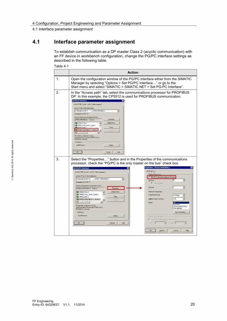
4.1 Interface parameter assignment
To establish communication as a DP master Class 2 (acyclic communication) withan FF device in workbench configuration, change the PG/PC interface settings asdescribed in the following table.Table 4-1
Action
1. Open the configuration window of the PG/PC interface either from the SIMATICManager by selecting “Options > Set PG/PC Interface…” or go to theStart menu and select “SIMATIC > SIMATIC NET > Set PG-PC Interface”.
2. In the “Access path” tab, select the communications processor for PROFIBUSDP. In this example, the CP5512 is used for PROFIBUS communication.
3. Select the “Properties…” button and in the Properties of the communicationsprocessor, check the “PG/PC is the only master on the bus” check box.

4 Configuration, Project Engineering and Parameter Assignment4.2 Hardware configuration
FF EngineeringEntry-ID: 64329637, V1.1, 11/2014 21
Siem
ens
AG20
14Al
lrig
hts
rese
rved
Action
4. To test the interface, select the “Diagnostics…” button and in the Diagnosticswindow, select the “Test” button.
1
2 3
The Diagnostics window provides you with the following information:1. The interface functions properly on PROFIBUS DP (“OK” in the output field)2. The engineering computer is the active node with address “0”3. The FF Link is the passive station on the bus and has address “6”
NOTICE Use “operation as the only master on the bus” only for workbenchcommissioning. For operation with a controller, use “PC internal (local)”.
4.2 Hardware configuration
This chapter includes the configuration steps to create an FF segment. Thecomponents consisting of the configuration computer with the PROFIBUS DPinterface card, FF Link and FF field device have been physically installed andcabled.
Note Before you start configuring, you should create a list that defines the cleardevices names (TAG names) that are unique project-wide and the addresses tobe configured for the FF devices. For FF field devices, use an address in therange from 20 to 35. This address range is valid for each FF segment.Addresses outside this range are only permitted in exceptional cases. For moreinformation on the address ranges, please refer to the “SIMATIC Process ControlSystem PCS 7 FOUNDATION Fieldbus” commissioning manual, Chapter“Device addresses”, Entry ID 70235901.

4 Configuration, Project Engineering and Parameter Assignment4.2 Hardware configuration
FF EngineeringEntry-ID: 64329637, V1.1, 11/2014 22
Siem
ens
AG20
14Al
lrig
hts
rese
rved
The following instructions describe the steps necessary to configure an FFsegment with a SITRANS P DS III pressure transmitter. The configuration listdefines FF address “21” and device name “PT111” for the device.Table 4-2
Action
1. Use the PCS 7 Wizard to create a new PCS 7 project with a CPU of your choice.NoteWorkbench configuration requires that a controller be configured in HW Config,but not physically connected.
2. Go to HW Config and in the hardware device catalog (profile: PCS7_V80) in thePROFIBUS DP tree, select the FF Link (IM 153-2 FF). Add the FF Link to thePROFIBUS DP segment.NoteThe configured address of the FF Link must match the physical address of the FFLink.
3. Add the FF field device (SITRANS P DS III) from the hardware device catalog,from the FOUNDATION FIELDBUS tree, to the FF subsystem. Assign an address,according to your configuration list, in the range from 20 to 35 to the device. FFaddress “21” is used in this example.
4. Double-click on the device icon (HW Config object) in HW Config to open theSITRANS P DS III.
5. In PDM, select the top hierarchy folder of the device and in the context menu,select “Object Properties”.
6. In “Object name:”, enter the device name “PT111” and select the “OK” button.NoteAfter saving, the changed device name is displayed uniformly in both PDM andHW Config.
7. Select the FF Link in HW Config to open the LifeList and in the FF Link contextmenu, select “SIMATIC PDM > Start LifeList”. Select the “Start” button to start thedevice search.It searches the FF subsegment and displays all accessible nodes.
NoteIn the condition at delivery from the plant, FF field devices have an address in therange from 248 and higher. In this example, the FF Link has FF address “16” andthe SITRANS P DS III FF has address “248”.

4 Configuration, Project Engineering and Parameter Assignment4.2 Hardware configuration
FF EngineeringEntry-ID: 64329637, V1.1, 11/2014 23
Siem
ens
AG20
14Al
lrig
hts
rese
rved
Action
8. Follow the instructions below to assign an HW Config object to the device:1. In the LifeList, select “PT111”.2. Select the “Assign address and TAG” button.3. Click on the “Select object” button.4. Select the respective HW Config object and click on the “OK” button.5. To change the address and name of the device, select the “Transfer>>”
button.
1
23
4
45

4 Configuration, Project Engineering and Parameter Assignment4.3 Device parameterization with SIMATIC PDM
FF EngineeringEntry-ID: 64329637, V1.1, 11/2014 24
Siem
ens
AG20
14Al
lrig
hts
rese
rved
4.3 Device parameterization with SIMATIC PDM
The following instructions describe the configuration steps necessary for a basicconfiguration of an FF device using the example of the SITRANS P DS III.Table 4-3
Action
1. Double-click on the device icon (HW Config object) in HW Config to open theSITRANS P DS III (“PT111”).
2. In PDM, select the top hierarchy folder of the device and in the context menu,select “Upload to PG/PC…”.
NoteAll device parameters will be read out and displayed in PDM.
3. In the PDM tree structure, go to the RB (resource block) area and change the“Alert Key” parameter to greater than “0”.
NoteThe value “0” means that the device was not commissioned, i.e. it was notinitialized.
4. To download the changed parameterization, select the RB and in the contextmenu, select “Download to device …”.

4 Configuration, Project Engineering and Parameter Assignment4.3 Device parameterization with SIMATIC PDM
FF EngineeringEntry-ID: 64329637, V1.1, 11/2014 25
Siem
ens
AG20
14Al
lrig
hts
rese
rved
Action
5. To change the RB mode, use the “Device > Modes” menu option and in the BlockMode Target area, select “Auto”.
NoteOnly one mode may be selected in this area. One exception, “Cas” and “Auto”activated simultaneously, is allowed. The “OOS” state has the highest priority.
6. Use the “Transfer” button to transfer the changes to the device. “Block ModeActual” changes to “Auto” mode.NoteIf an error occurs, “OOS” (Out Of Service) mode will be displayed. The BlockError area provides specific information on troubleshooting that can also be readin the manual.
7. Go to the TB1 (Transducer Block 1) area and change the “Alert Key” parameterto greater than “0”.
8. Set the device-specific parameters such as primary value type, sensor value andtemperature ranges.
9. To download the parameters and change the mode, follow steps 4 to 7 with TB1.10. Go to the TB2 (Transducer Block 2) area and change the “Alert Key” parameter
to greater than “0”.11. Set the device-specific parameters on the device display, e.g. value type
displays.NoteIf a measured value configured with CiF is to be displayed by another device,select the interconnected block (Connection Editor) in select values.
12. To download the parameters and change the mode, follow steps 4 to 7 with TB2.13. Go to the FB1 (Function Block 1) area and change the “Alert Key” parameter to
greater than “0”.14. Set the device-specific parameters for, e.g., analog (AI / AO) and digital
communication (DI / DO) or closed-loop (PD / PID) and open-loop controlfunctions.NoteUse the same factors and settings for measured value and output scaling. In theCFC, you can define scaling for the measured value later in the configurationprocedure.
15. Change the “Linearization type” parameter to direct, indirect or indirect squareroot.

4 Configuration, Project Engineering and Parameter Assignment4.3 Device parameterization with SIMATIC PDM
FF EngineeringEntry-ID: 64329637, V1.1, 11/2014 26
Siem
ens
AG20
14Al
lrig
hts
rese
rved
Action
16. The process-relevant limits (alarms and warnings) are not parameterized in thedevice; they are configured centrally for the respective measured value in theCFC and monitored and operated via the OS.NoteFor some devices, it is possible to parameterize maintenance requests. In thiscase, the maintenance request is parameterized if necessary and operated usingPCS 7 Asset Management.
17. To download the parameters and change the mode, follow steps 4 to 7 with therelevant FBs.
18. Follow steps 14 to 19 for the remaining FBs to which you have already assignedinput or output addresses in HW Config.NoteThe parameterization of FB2 and FB3 in PDM allows you to use the sensor andelectronics temperature or the measured value in modified form, e.g. in anotherunit of measurement, for the configuration in the CFC.
Note Use “File > Export” to export the parameters of a device. You can use this exportfile for basic parameterization of several identical devices or if replacement isnecessary.

5 Operation of the Application5.1 Scenario A – Expanding the project by an FF segment
FF EngineeringEntry-ID: 64329637, V1.1, 11/2014 27
Siem
ens
AG20
14Al
lrig
hts
rese
rved
5 Operation of the Application
The following chapters discuss and describe two typical FF scenarios.
5.1 Scenario A – Expanding the project by an FF segment
In this scenario, an existing PCS 7 project is expanded by an FF segment with fivefield devices (using the example of the SITRANS P DS III, SIPART PS2, SITRANSTH400, 3051 pressure transmitter and SITRANS LR250).
PreparationParameterize the field devices as described in Chapter 4.2 “Hardwareconfiguration” and Chapter 4.3 “Device parameterization with SIMATIC PDM” andensure that the names and addresses of the following configuration list are correct.Table 5-1
Plant Device Name Address
1. RMT1 SITRANS P DS III PT111 212. RMT1 3051 PT112 223. RMT1 SITRANS TH400 TT111 234. RMT1 SIPART PS2 VP111 245. RMT1 SITRANS LR250 LT111 25
To check the segment configuration (electrical quantities of the segment andquantity framework), the FF segment is calculated using the SIMATIC FieldbusCalculator. In addition, the user data volume for the FF segment is considered.
Note The SIMATIC Fieldbus Calculator is available as an application example, EntryID 53842953.
The following configuration is used to check the segment.Figure 5-1
Plant bus
200 m
100 m
40 m 30 m
17.5 mA
20 mA 11.5 mA 11 mA 12.5 mA
100 m

5 Operation of the Application5.1 Scenario A – Expanding the project by an FF segment
FF EngineeringEntry-ID: 64329637, V1.1, 11/2014 28
Siem
ens
AG20
14Al
lrig
hts
rese
rved
Checking the cyclic data volume and the segment configurationTo check the user data volume (value and status), one measured value is assumedfor each device.Table 5-2
Segment Number offield devices
User data volume(5 bytes per device)
FF-1 5 25 bytes
The number of field devices of the example corresponds to a smaller FFconfiguration. The small number of devices and user data volume results in thefollowing advantages: The segment can be extended by additional devices. A fast macro cycle can be implemented. Additional measured values of existing devices can be additionally configured
in HW Config. The FF segment can be extended by CiF closed-loop controls and
interconnections.The figure below shows the calculation and evaluation of the electrical quantities ofthe FF segment in the SIMATIC Fieldbus Calculator.Figure 5-2
The evaluation of the data entered provides you with the information that theconfiguration can be operated with the quantity framework and line lengths.
5 Operation of the Application5.1 Scenario A – Expanding the project by an FF segment
FF EngineeringEntry-ID: 64329637, V1.1, 11/2014 29
Siem
ens
AG20
14Al
lrig
hts
rese
rved
Configuring the hardwareIn order to proceed, the device parameterization and hardware addressing of theFF Link must have been completed.Table 5-3
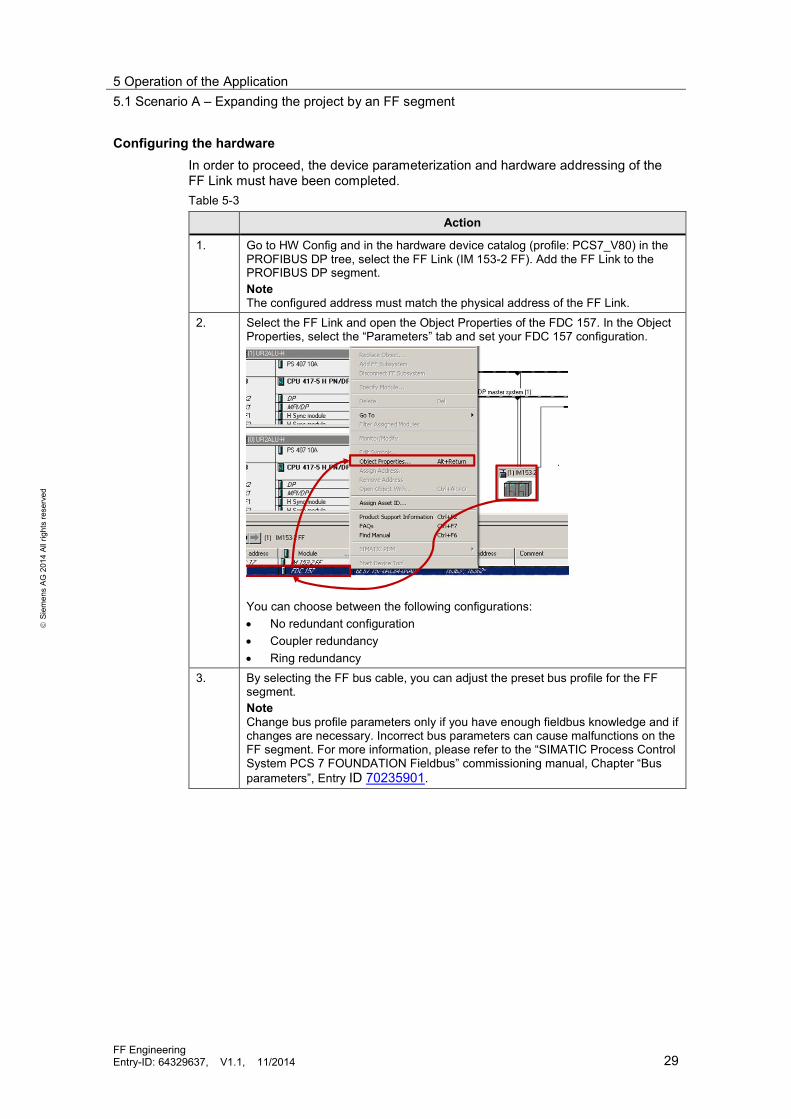
Action
1. Go to HW Config and in the hardware device catalog (profile: PCS7_V80) in thePROFIBUS DP tree, select the FF Link (IM 153-2 FF). Add the FF Link to thePROFIBUS DP segment.NoteThe configured address must match the physical address of the FF Link.
2. Select the FF Link and open the Object Properties of the FDC 157. In the ObjectProperties, select the “Parameters” tab and set your FDC 157 configuration.
You can choose between the following configurations: No redundant configuration Coupler redundancy Ring redundancy
3. By selecting the FF bus cable, you can adjust the preset bus profile for the FFsegment.NoteChange bus profile parameters only if you have enough fieldbus knowledge and ifchanges are necessary. Incorrect bus parameters can cause malfunctions on theFF segment. For more information, please refer to the “SIMATIC Process ControlSystem PCS 7 FOUNDATION Fieldbus” commissioning manual, Chapter “Busparameters”, Entry ID 70235901.

5 Operation of the Application5.1 Scenario A – Expanding the project by an FF segment
FF EngineeringEntry-ID: 64329637, V1.1, 11/2014 30
Siem
ens
AG20
14Al
lrig
hts
rese
rved
Action
4. Add all relevant FF devices from the hardware device catalog to the “FF-Subsystem” and assign an address according to your configuration list.
NoteWhen being inserted, the HW Config object names receive a default object name(initial values).
5. Go to the SIMATIC Manager and select “View > Process Device Network View”.
6. In the “Process Device Network View”, select the FF subsegment with the addeddevices within your automation system.NoteIf communication with the device has not yet taken place, the device icon (PDMobject) will be displayed in blue.
7. Select a PDM object and in the context menu, select “Object Properties…”.8. Change the object name according to your configuration list and select the “OK”
button.
9. Follow steps 6 and 7 for each FF device (except the FF Link) and return to HWConfig.
10. Physically connect a device to the FF segment. Start the LifeList and assign thisdevice to the respective HW Config object. In the assignment dialog box, use the
5 Operation of the Application5.1 Scenario A – Expanding the project by an FF segment
FF EngineeringEntry-ID: 64329637, V1.1, 11/2014 31
Siem
ens
AG20
14Al
lrig
hts
rese
rved
Actionobject names from your configuration list.NoteThe assignment is not necessary if the object names and addresses of the HWConfig object are identical with the device information in the LifeList.For instructions for assigning field devices to HW Config objects, please refer toChapter 4.2 “Hardware configuration”.
11. Repeat step 4 for each device of the FF segment until you have assigned alldevices.NoteIf you are sure that there will be no address conflict, you can simultaneouslyconnect all devices to one FF segment. Then assign each device to an HWConfig object.
12. For the FBs to be configured, assign an I/O address (input or output address) toeach device.NoteWhen addressing multiple device FBs in HW Config, parameterize the same FBsfor the respective device also in SIMATIC PDM.
13. Assign a symbolic name to each input and output address. To do so, select theaddress and in the context menu, select “Edit symbols…”.
14. In the next window, enter a device-specific name, e.g. for a pressure transmitterfor the measured value (e.g., PT111_PV) and the associated measured valuestatus (PT111_QC). The abbreviation “PV” means primary value and “QC” standsfor quality code. Select “OK” or “Apply” to apply the entries.NoteFor the names of the devices, please refer to the plant’s planning documents andderive the symbolic names from them.
15. Select the FF subsystem and in the context menu, select “Object Properties…”.16. In the FF subsystem object properties, select the “Properties” button.17. In the next window, select the “Macro cycle” tab.18. Select the “Calculate schedule” button and check if the values meet your project
requirements (also in graphical form). Customize the macro cycle to yourrequirements and schedule a reserve for future extensions.NoteThe following changes require macro cycle calculations: Number of devices on the FF segment Device FB configuration Interconnections in the Connection Editor
19. Select the “Station > Save and Compile” menu option to compile the entirehardware configuration.
20. Select the “PLC > Download to Module…” menu option to download theconfiguration to the automation system. First the configuration is downloaded tothe automation system. Then the scheduler is transferred to each FF node in theFF segment.
21. Select the FF Link to read out and save the device parameters and in the FF Linkcontext menu, select “SIMATIC PDM > Upload to PC/PG …”. Select the “Objectwith all subordinate objects and networks” option to read out all devices of the FFsegment.NoteAlternatively, you can also open each individual device and read out, check andsave all parameters.
5 Operation of the Application5.1 Scenario A – Expanding the project by an FF segment
FF EngineeringEntry-ID: 64329637, V1.1, 11/2014 32
Siem
ens
AG20
14Al
lrig
hts
rese
rved
Action
22. Select the FF Link and in the FF Link context menu, select “Object Properties…”.23. In the next window, select the “Load FF segment” tab.24. Select the “Only load FF Link and FF devices when modified” option.
NoteBy selecting this option, an FF segment will only be loaded when configurationchanges are made to the FF segment.
NOTICE The following behavior occurs when loading an FF segment:Loading parameters: When loading the device parameters, the relevantdevice cannot be accessed while loading.Redundant configuration and single CPU: When loading the scheduler, theentire segment cannot be accessed.
CFC configurationThe symbolic names of the input and output addresses for the FBs of the FFdevices are necessary to continue the configuration process.In the CFC, the channel blocks of the Advanced Process Library (APL) are used tointerconnect the hardware (symbolic names). Depending on the signal type, youcan use the following blocks.Table 5-4
Signal type Block name FB number
Analog input FbAnIn FB 1813Analog output FbAnOut FB 1814Digital input FbDiIn FB 1815Digital output FbDiOut FB 1816
The further configuration steps, i.e. interconnecting the channel blocks with, e.g.,measured value display blocks or designing closed-loop controls, are identical withthe configuration for PROFIBUS PA, HART and conventional field devices.
Note For configuring, use the detailed configuring guides, for example:
“SIMATIC Process Control System PCS 7 Compendium Part A – ConfigurationGuidelines”, Entry ID 63187279
“SIMATIC Process Control System PCS 7 Engineering System (V8.1)”, Entry ID90663380
“SIMATIC Process Control System PCS 7 Compendium Part D – Operation andMaintenance”, Entry ID 63200194

5 Operation of the Application5.2 Scenario B – Device replacement with download scenarios
FF EngineeringEntry-ID: 64329637, V1.1, 11/2014 33
Siem
ens
AG20
14Al
lrig
hts
rese
rved
5.2 Scenario B – Device replacement with downloadscenariosThe following scenario describes the procedure for replacing an FF device with anidentical device, i.e. the same type and the same firmware version.
Note The device replacement description describes the configuration andparameterization options. For the environment-specific requirements and rules tobe followed, please contact the plant operator.
A device can be replaced in different ways. In this scenario, workbenchcommissioning is performed to prevent an address conflict. If you can exclude anaddress conflict, continue with “Parameterization”.
Address assignmentAssign the address as described in Chapter 4.2 “Hardware configuration” using thename and address of your configuration list.
ParameterizationReplace the defective device in the field (FF segment) with the replacement device.The following instructions describe the steps necessary to integrate thereplacement device.
Table 5-5
Action
1. Go to HW Config and assign the address and device name as described inChapter 4.2 “Hardware configuration”.NoteIt is mandatory that you use the HW Config object.
2. Double-click on the device icon in HW Config to open the device.3. In PDM, select the top hierarchy folder of the device and in the context menu,
select “Load to Devices…”.

5 Operation of the Application5.3 Scenario C – Implementing a local display
FF EngineeringEntry-ID: 64329637, V1.1, 11/2014 34
Siem
ens
AG20
14Al
lrig
hts
rese
rved
Action
4. In the “Load to Devices” window, check the “Load Schedule to Devices” checkbox (1) and select the “Start” button (2).
1
2
The device parameters and the scheduler are loaded to the replacement device.NoteAs no additional data is parameterized and loaded, it is not necessary torecalculate the macro cycle.
5.3 Scenario C – Implementing a local displayThe following scenario describes the procedure for the configuration of a localdisplay. This shows the temperature of a SITRANS TH400 on the display of apressure transmitter, alternating with the pressure value.This scenario focuses in the configuring of the necessary connections via theconnection editor and the parameter assignment of the pressure transmitter displayvia SIMATIC PDM.The following example assumes that all the FF segment nodes are alreadypreconfigured in the HW Config and pre-parameterized.
ConfigurationTable 5-6
Action
1. Switch to the HW Config.2. Select the FF link of the FF segment for which the local display is being configured
and select "SIMATIC PDM > Start connection editor" in the context menu of the FFlink.
3. Select the parameters:"IN" from input "FB 4 (PID)" of SITRANS P DS III"OUT" from input "FB 1 (AI)" of SITRANS TH400
4. Press the "Save" button and then "Close" to accept the connections.

5 Operation of the Application5.3 Scenario C – Implementing a local display
FF EngineeringEntry-ID: 64329637, V1.1, 11/2014 35
Siem
ens
AG20
14Al
lrig
hts
rese
rved
Action
5. Select the "FF subsystem" and choose "Object properties..." in the context menu.6. Press the "Properties" button in the object properties on the FF subsystem.7. Select the "Macro cycle" tab in the next window.8. Press the "Calculate schedule" button and check whether the values (even the
graphics) coincide with your project requirements. Adjust the macro cycle to yourrequirements and plan a back-up for future expansions.
9. Compile the entire hardware configuration via the menu command "Station> Saveand compile".
10. Upload the configuration to the automation system via the menu command "Targetsystem> Load into module...". First, the configuration is loaded into the automationsystem. Then the scheduler is transmitted to each FF node in the FF segment.
11. Open the SITRANS P DS III ("PT111") by double-clicking the device icon (HWConfig object) in the HW Config.
12. Select the hierarchy folder "021 TB 2 (Custom)" and then "Load into PG/PC..." inthe context menu.NoteAll device parameters of the Transducer Block 2 are read out and displayed inPDM.
13. In a free display range in the "Collection Direction" area, select the PID block input(IN parameter) for the temperature of the SITRANS TH400.NoteIn addition to this, you can also enter a unique name (maximum 5 characters) forthe on-screen display.
14. Select the hierarchy folder for the TB 2 and then "Load into device..." in the contextmenu.NoteThe display of the SITRANS P DS III switches continuously between the pressurereading and the temperature of the SITRANS TH400.
15. Save the parameters and close SIMATIC PDM.

6 Further notes, tips and tricks, etc.
FF EngineeringEntry-ID: 64329637, V1.1, 11/2014 36
Siem
ens
AG20
14Al
lrig
hts
rese
rved
6 Further notes, tips and tricks, etc.PDM – Downloading all parameters
For a device with basic parameterization, you can transfer all parameter changes indifferent blocks to the device in one step.To download the parameters, select the top hierarchy folder of the device in PDMand in the context menu, select “Download to device…”.Figure 6-1
Note All blocks (RB, TB and FB) will be transferred to the device, whose “Alert Key” isset to “1” or greater.
PDM – Changing the device nameIf the device name (object name) in the device differs from the device nameparameterized in PDM and HW Config, you can use the “Assign address and TAG”dialog box to write the parameterized device name to the device as described inthe following table.Table 6-1
Action
1. Double-click on the device icon in HW Config to open the device.NoteThe configured device address must match the actual device address. Inaddition, the selected device (device icon in HW Config) must be compatible withthe connected device.
2. In PDM, select the top hierarchy folder and select the “Device > Assign addressand TAG” menu option.The assignment dialog box opens.

6 Further notes, tips and tricks, etc.
FF EngineeringEntry-ID: 64329637, V1.1, 11/2014 37
Siem
ens
AG20
14Al
lrig
hts
rese
rved
Action
3. The assignment dialog box displays the offline project data (1) and the onlinedevice data (2).
1 2
NoteIn area (2), no information is available except the default setting of the FFaddress, as the device was not identified at address 21. Here, an address otherthan FF address “21” can also be entered.
4. Follow the steps below to assign the configured device name to the device:1. Select the “Find” button to identify the device connected at address “21”.2. The read information (object name, FF address and device information) is
displayed.3. To write the offline address and offline name to the device, select the
“Transfer>>” button.
1
32

6 Further notes, tips and tricks, etc.
FF EngineeringEntry-ID: 64329637, V1.1, 11/2014 38
Siem
ens
AG20
14Al
lrig
hts
rese
rved
Macro cycleThe following information can be derived from the graphical representation of themacro cycle display.Figure 6-2 – Representation of macro cycle
1
1
1
2 3
4
5
Table 6-2
Color Description
1. Yellow Acyclic communication percentage2. Light green Reserve percentage for cyclic communication3. Dark green Cyclic communication percentage4. Orange Downloading the configuration possible only with AS stop and
generates high bus load5. Red Downloading the configuration not possible
NOTICE When changes to the macro cycle are not made in the macro cycle window,use the “Cancel” button to close the window. If you use the “OK” buttonwithout any changes, compile and download AS will be required.

7 Related literature
FF EngineeringEntry-ID: 64329637, V1.1, 11/2014 39
Siem
ens
AG20
14Al
lrig
hts
rese
rved
7 Related literature7.1 Bibliography
This list is by no means complete and only presents a selection of relatedreferences.Table 7-1
Topic Title / Link
/1/ Industrialcommunication
Catching the Process Fieldbus -An Introduction to PROFIBUS for Process AutomationPublisher: Siemens MilltronicsISBN 978-0978249519
7.2 Internet linksIn addition to the list of installation and mounting documents in “Hardwareinstallation”, the table below provides an additional selection of sources ofinformation. This list is by no means complete and only provides a selection ofuseful information.Table 7-2
Topic Title / Link
\1\ Siemens Industry OnlineSupport
http://support.automation.siemens.com
\2\ Download page of this entry http://support.automation.siemens.com/WW/view/en/64329637
\3\ SIMATIC Process ControlSystem PCS 7 CompendiumPart A – ConfigurationGuidelines
http://support.automation.siemens.com/WW/view/en/63187279
\4\ SIMATIC Process ControlSystem PCS 7 CompendiumPart D – Operation andMaintenance
http://support.automation.siemens.com/WW/view/en/63200194
\5\ Fieldbus Foundation website http://www.fieldbus.org
\6\ PCS 7 Quick Access(landing page)
http://support.automation.siemens.com/WW/view/en/63481413
\7\ Calculation and Design ofFieldbus Segments with theSIMATIC Fieldbus Calculator
http://support.automation.siemens.com/WW/view/en/53842953
\8\ SIMATIC Process ControlSystem PCS 7 FOUNDATIONFieldbus
http://support.automation.siemens.com/WW/view/en/70235901

8 History
FF EngineeringEntry-ID: 64329637, V1.1, 11/2014 40
Siem
ens
AG20
14Al
lrig
hts
rese
rved
8 History
Table 8-1
Version Date Modifications
V1.0 01/2013 First versionV1.1 11/2014 Released for PCS 7 V8.1, scenario 3 “Implementing a local
display” added


![Profibus PA Fieldbus Display [ Revision 2 ] and Fieldbus ... Instruments... · Profibus PA Fieldbus Display [ Revision 2 ] and Fieldbus Indicator Fieldbus Interface Guide. ... Siemens](https://img.pdfslide.us/doc/110x75/5b2fe38e7f8b9ae16e8da83d/profibus-pa-fieldbus-display-revision-2-and-fieldbus-instruments.jpg)