Embed Size (px)
Citation preview
F1024/01
FIELDBUSCOMPONENTSFORFOUNDATION
FIELDBUS™
2 /0407 Hans Turck GmbH & Co.KG • D–45466 Mülheim/Ruhr • Tel. 0208/4952-0 • Fax 0208/4952-264 • E-Mail: [email protected] • Internet: www.turck.com
Fieldbus systems in process auto-mationFieldbus systems have become prevalent in the fi eld of process automation in addition to decentral peripheral systems.FOUNDATION fi eldbus™ and PROFIBUS-PA fi eldbus systems are now the esta-blished fi eldbuses in this fi eld (for further information about the TURCK-product portfolio and in particular PROFIBUS-PA products, please see catalogue D301026).The advantages of both of these systems are the process adapted specifi cation and the real interoperability of fi eld devices from various manufacturers and their compatibility with external host systems.
Both the FOUNDATION fi eldbus™ and PROFIBUS-PA fi eldbus fulfi l the demands of the chemical, pharmaceutical and petrochemical industries. The most important features are :• standardised user profi le• suited for use in explosion hazardous areas• bus supply and fi eldbus communication via shielded and twisted pair cables• online device exchange without affecting system processes• diagnostics for Asset ManagementComprehensive tests performed by the industry, interest groups and committees confi rm the unlimited suitability of both bus systems for use in process engineering.
TURCK fi eldbus componentsWith TURCK products you are not tied down to company-specifi c fi eldbus technologies, but can choose the most suitable bus product for your application from a comprehensive product spectrum.
TURCK offers the complete range for all conventional industrial fi eldbus systems in factory and process automation, no matter whether you require junction modules, connection products or even complete systems.
TURCK fi eldbus components are spe-cially designed for the harsh industrial environment. The extensive product line for diverse applications fulfi ls all demands and provides Plug & Play connectivity to ensure fast and easy connection of the fi eld device to the control system. Fieldbus cables and cordsets in various fi eldbus standards and materials and with different connector types are available for data transfer and voltage supply of the stations.
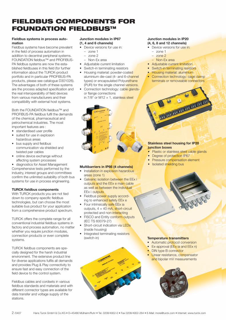
Junction modules in IP67 (1, 4 and 6 channels)• Device versions for use in: – zone 1 – zone 2 – Non-Ex area• Adjustable current limitation• Switch-in terminating resistors• Housing material: powder-coated aluminium die-cast (4- and 6-channel types) or encapsulated Polyurethane (PUR) for the single channel versions.• Connection technology: cable glands- or fl ange connections in 7/8“ or M12 × 1, stainless steel
Junction modules in IP20 (4, 6, 8 and 12 channels)• Device versions for use in: – zone 1 – zone 2 – Non-Ex area• Adjustable current limitation• Switch-in terminating resistors• Housing material: aluminium• Connection technology: cage clamp terminals or removeable connectors
Multibarriers in IP66 (4 channels)• Installation in explosion hazardous areas (zone 1)• Galvanic isolation between the EEx i outputs and the EEx e main cable as well as between the individual EEx i outputs• Fieldbus power supply accord- ing to enhanced safety EEx e• Four intrinsically safe EEx ia outputs, 4 × 40 mA, short-circuit protected and non-interacting• FISCO and Entity conform outputs (IEC TS 60079-27)• Short-circuit indication via LEDs (inside housing)• Integrated terminating resistors (switch-in) Temperature transmitters
• Automatic protocol conversion• Ex-approval (EEx ia and EEx n)• DIN type B connector• Linear resistance, compensator and bipolar mV measurements
FIELDBUS COMPONENTS FOR FOUNDATION FIELDBUS™
Stainless steel housing for IP20 junction boxes • Plastic or stainless steel cable glands• Degree of protection IP67• Pressure compensation element• Isolated shielding bus
1
Hans Turck GmbH & Co.KG • D–45466 Mülheim/Ruhr • Tel. 0208/4952-0 • Fax 0208/4952-264 • E-Mail: [email protected] • Internet: www.turck.com 3 /0407
Field device overvoltage protection • Aluminium die-cast housings• Connection to potential equalisation via M5 × 1 bolt on housing• Degree of protection: IP67 and IP20The data sheets are available under www.turck.com
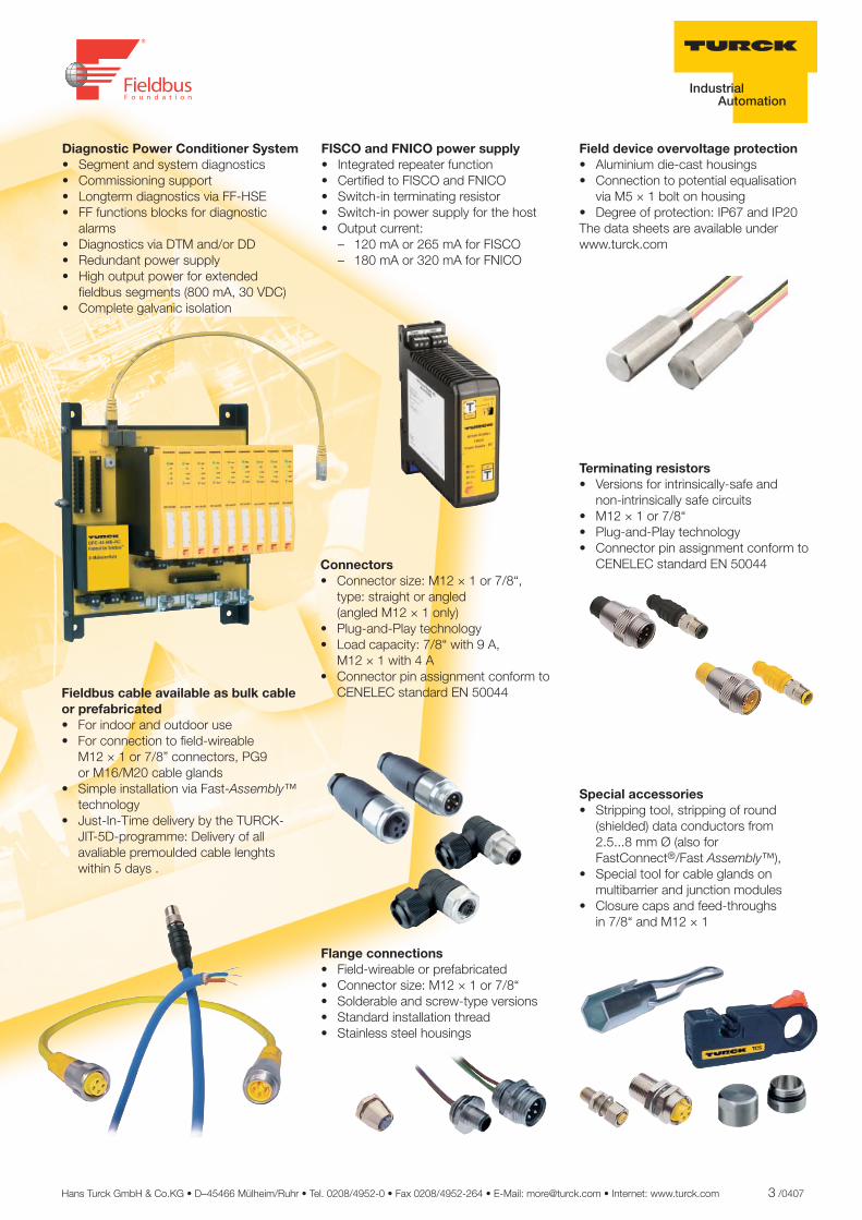
Fieldbus cable available as bulk cable or prefabricated• For indoor and outdoor use• For connection to fi eld-wireable M12 × 1 or 7/8” connectors, PG9 or M16/M20 cable glands• Simple installation via Fast-Assembly™ technology• Just-In-Time delivery by the TURCK- JIT-5D-programme: Delivery of all avaliable premoulded cable lenghts within 5 days .
Connectors• Connector size: M12 × 1 or 7/8“, type: straight or angled (angled M12 × 1 only)• Plug-and-Play technology• Load capacity: 7/8“ with 9 A, M12 × 1 with 4 A• Connector pin assignment conform to CENELEC standard EN 50044
Terminating resistors• Versions for intrinsically-safe and non-intrinsically safe circuits• M12 × 1 or 7/8“ • Plug-and-Play technology• Connector pin assignment conform to CENELEC standard EN 50044
Flange connections• Field-wireable or prefabricated• Connector size: M12 × 1 or 7/8“ • Solderable and screw-type versions• Standard installation thread• Stainless steel housings
Special accessories• Stripping tool, stripping of round (shielded) data conductors from 2.5...8 mm Ø (also for FastConnect®/Fast Assembly™),• Special tool for cable glands on multibarrier and junction modules • Closure caps and feed-throughs in 7/8“ and M12 × 1
Diagnostic Power Conditioner System• Segment and system diagnostics• Commissioning support• Longterm diagnostics via FF-HSE• FF functions blocks for diagnostic alarms• Diagnostics via DTM and/or DD• Redundant power supply• High output power for extended fi eldbus segments (800 mA, 30 VDC)• Complete galvanic isolation
FISCO and FNICO power supply• Integrated repeater function • Certifi ed to FISCO and FNICO• Switch-in terminating resistor• Switch-in power supply for the host• Output current: – 120 mA or 265 mA for FISCO – 180 mA or 320 mA for FNICO

4 /0407 Hans Turck GmbH & Co.KG • D–45466 Mülheim/Ruhr • Tel. 0208/4952-0 • Fax 0208/4952-264 • E-Mail: [email protected] • Internet: www.turck.com
THE TURCK PRODUCT DATA BASE IN THE WORLD WIDE WEB
Your are looking for a customised solution concerning your application or searching for a particular product? You want to order or download catalogues, data sheets, manuals, software or confi guration fi les? For comprehensive information, please go to www.turck.com
1
11
1
FIELDBUS COMPONENTS FOR FOUNDATION FIELDBUS™
Fieldbus cablesCable technology– Basics 106Cable FBY-.../SD... 108Cable FBY-BK/LD... 109Cable FBH-YE... 110Cable FBA-YE... 111Cable 492A.../Cable 492BA... 112Cable FB4910-BK... 113
Junction boxesJunction boxes by TURCK 41Junction boxes in IP67 with short-circuit protection 42Junction boxes in IP67 without short-circuit protection 66Junction boxes in IP20 with short-circuit protection 90Junction boxes in IP20 without short-circuit protection 98
2
3
4
5
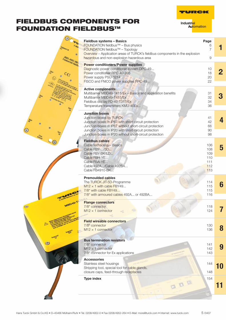
Fieldbus systems – Basics PageFOUNDATION fi eldbus™ – Bus physics 6FOUNDATION fi eldbus™ – Topology 7Overview – Application areas of TURCK’s fi eldbus components in the explosion hazardous and non-explosion hazardous area 9
Power conditioners/Power supplies Diagnostic power conditioner system DPC-49... 10 Power conditioner RPC-49-205 18Power supply PSU-3214 20FISCO and FNICO power supplies RPC-49... 22
Active componentsMultibarrier MBD49-T415/Ex – Basics and application benefi ts 31Multibarrier MBD49-T415/Ex 32Fieldbus display FD-49-T317/Ex 34Temperature transmitters KMU-40Ex... 36
Premoulded cables The TURCK JIT-5D-Programme 114M12 × 1 with cable FBY49... 1157/8“ with cable FBY49... 1157/8“ with armoured cables 492A... or 492BA... 116
6
Flange connectors 7/8“ connector 118M12 × 1 connector 124 7Field wireable connectors 7/8“ connector 130M12 × 1 connector 136 8Bus termination resistors 7/8“ connector 141M12 × 1 connector 1427/8“ connector for Ex applications 143
9Accessories Stainless steel housings 144Stripping tool, special tool for cable glands, closure caps, feed-through receptacles 148
10Type index 154
Hans Turck GmbH & Co.KG • D–45466 Mülheim/Ruhr • Tel. 0208/4952-0 • Fax 0208/4952-264 • E-Mail: [email protected] • Internet: www.turck.com 5 /0407
6 /0407 Hans Turck GmbH & Co.KG • D–45466 Mülheim/Ruhr • Tel. 0208/4952-0 • Fax 0208/4952-264 • E-Mail: [email protected] • Internet: www.turck.com
FOUNDATION fi eldbus™ – Bus physics With the publication of the international standard IEC 61158-2 in October 1994, a suitable transmission technology was determined and internationally specifi ed for the application areas of FOUNDATION fi eldbus™ and PROFIBUS-PA. This was later integrated into the European stan-dards as EN 61158-2.
Both systems comply with IEC 61158-2 and operate on the voltage mode with a transmission speed of 31.25 kBit/s. In this way the data packages are modulated onto the supply voltage for the fi eldbus station and transmitted via a shielded two-wire cable (see Fig. 1).
These bus physics offer a decisive advantage: fi eldbus communication and power supply of the bus station can be implemented using a single cable. These bus physics lead to enhanced operational safety and lower costs compared with the conventional fi eldbus solution used up to this point with its additional wiring effort.
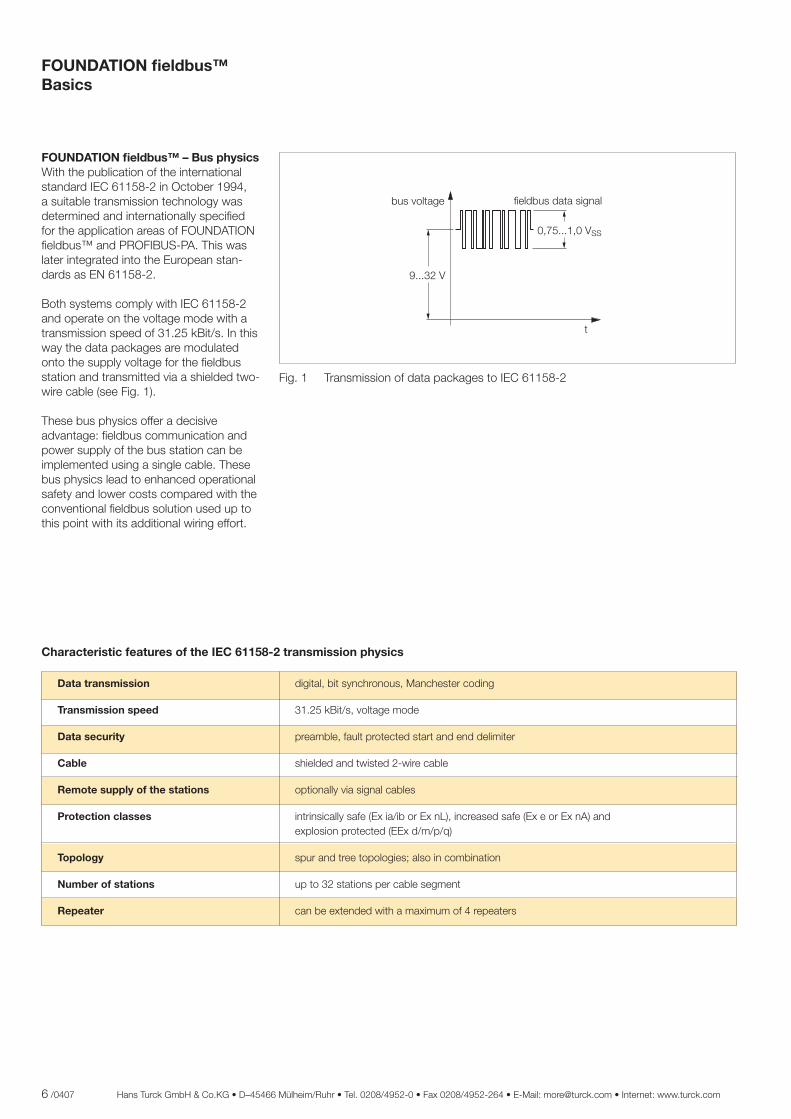
Fig. 1 Transmission of data packages to IEC 61158-2
Data transmission digital, bit synchronous, Manchester coding
Transmission speed 31.25 kBit/s, voltage mode
Data security preamble, fault protected start and end delimiter
Cable shielded and twisted 2-wire cable
Remote supply of the stations optionally via signal cables
Protection classes intrinsically safe (Ex ia/ib or Ex nL), increased safe (Ex e or Ex nA) and explosion protected (EEx d/m/p/q)
Topology spur and tree topologies; also in combination
Number of stations up to 32 stations per cable segment
Repeater can be extended with a maximum of 4 repeaters
��������
�
����� ����
����������� ��������������������
Characteristic features of the IEC 61158-2 transmission physics
FOUNDATION fi eldbus™Basics
1
Hans Turck GmbH & Co.KG • D–45466 Mülheim/Ruhr • Tel. 0208/4952-0 • Fax 0208/4952-264 • E-Mail: [email protected] • Internet: www.turck.com 7 /0407
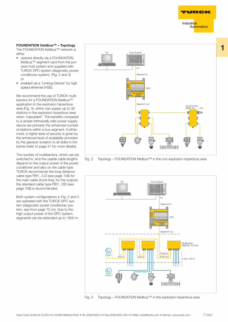
FOUNDATION fi eldbus™ – TopologyThe FOUNDATION fi eldbus™ network is either • opened directly via a FOUNDATION fi eldbus™ segment card from the pro- cess host system and supplied with TURCK DPC system (diagnostic power conditioner system) (Fig. 2 and 3) or • enabled via a “Linking-Device” by high speed ethernet (HSE).
We recommend the use of TURCK multi-barriers for a FOUNDATION fi eldbus™ application in the explosion hazardous area (Fig. 3), which can supply up to 32 stations in the explosion hazardous area when “cascaded”. The benefi ts compared to a simple intrinsically safe power supply device are primarily the enhanced number of stations within a bus segment. Further-more, a higher level of security is given by the enhanced level of availability provided by the galvanic isolation to all sides in the barrier (refer to page 31 for more details).
The number of multibarriers, which can be switched in, and the usable cable lengths depend on the output power of the power conditioner and also on the cable type. TURCK recommends the long-distance cable type FBY.../LD (see page 109) for the main cable (trunk line); for the outputs the standard cable type FBY.../SD (see page 108) is recommended.
Both system confi gurations in Fig. 2 and 3 are operated with the TURCK DPC sys-tem (diagnostic power conditioner sys-tem, see from page 10 on). Due to the high output power of the DPC system, segments can be extended up to 1900 m.
Fig. 2 Topology – FOUNDATION fi eldbus™ in the non-explosion hazardous area
Fig. 3 Topology – FOUNDATION fi eldbus™ in the explosion hazardous area
���
���� �!���"��
���"������
���"�������
�
#��$�������%#&&� '��� ����( )%
���������������� �������������������������������� ���������������� ���������������� ���������������� ���������������� ���������������� ���������������� �������������������������������� ��������������������������������
������������������� �������������������������������� ���������������� ���������������� ���������������� ���������������� ���������������� ���������������� �������������������������������� ��������������������������������
))%��*����
���� �!���"
+,��-���+,��-����))%��
*����
��
���"������
���"�������
�
"�%�� ��"
�������
.������,,��,
.&�'� +' �()%
8 /0407 Hans Turck GmbH & Co.KG • D–45466 Mülheim/Ruhr • Tel. 0208/4952-0 • Fax 0208/4952-264 • E-Mail: [email protected] • Internet: www.turck.com
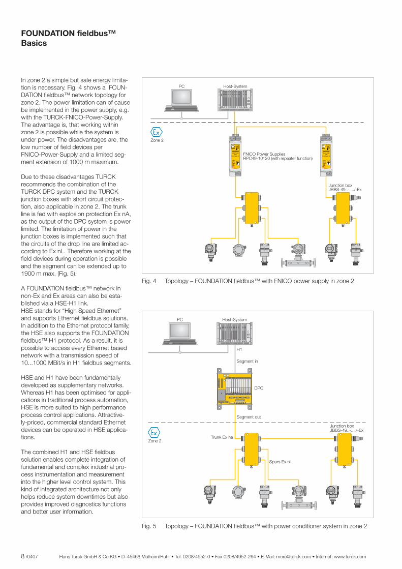
Fig. 4 Topology – FOUNDATION fi eldbus™ with FNICO power supply in zone 2
Fig. 5 Topology – FOUNDATION fi eldbus™ with power conditioner system in zone 2
In zone 2 a simple but safe energy limita-tion is necessary. Fig. 4 shows a FOUN-DATION fi eldbus™ network topology for zone 2. The power limitation can of cause be implemented in the power supply, e.g. with the TURCK-FNICO-Power-Supply. The advantage is, that working within zone 2 is possible while the system is under power. The disadvantages are, the low number of fi eld devices per FNICO-Power-Supply and a limited seg-ment extension of 1000 m maximum.
Due to these disadvantages TURCK recommends the combination of the TURCK DPC system and the TURCK junction boxes with short circuit protec-tion, also applicable in zone 2. The trunk line is fed with explosion protection Ex nA, as the output of the DPC system is power limited. The limitation of power in the junction boxes is implemented such that the circuits of the drop line are limited ac-cording to Ex nL. Therefore working at the fi eld devices during operation is possible and the segment can be extended up to 1900 m max. (Fig. 5).
A FOUNDATION fi eldbus™ network in non-Ex and Ex areas can also be esta-blished via a HSE-H1 link. HSE stands for “High Speed Ethernet” and supports Ethernet fi eldbus solutions. In addition to the Ethernet protocol family, the HSE also supports the FOUNDATION fi eldbus™ H1 protocol. As a result, it is possible to access every Ethernet based network with a transmission speed of 10...1000 MBit/s in H1 fi eldbus segments.
HSE and H1 have been fundamentally developed as supplementary networks. Whereas H1 has been optimised for appli-cations in traditional process automation, HSE is more suited to high performance process control applications. Attractive-ly-priced, commercial standard Ethernet devices can be operated in HSE applica-tions.
The combined H1 and HSE fi eldbus solution enables complete integration of fundamental and complex industrial pro-cess instrumentation and measurement into the higher level control system. This kind of integrated architecture not only helps reduce system downtimes but also provides improved diagnostics functions and better user information.
���
���� �!���"��
���"������
���"�������
�
#��$�������%#&&� '��� ����( )%
���������������� �������������������������������� ���������������� ���������������� ���������������� ���������������� ���������������� ���������������� �������������������������������� ��������������������������������
*�����+,��-�)%���
�/�,��)%���
��
������������������
����������� ������
����!�� �� ��
��
�� ����
�"��
������������������
����������� ������
����!�� �� ��
��
�� ����
�"
���� �!���"��
#��$�������%#&&� '��� ����( )%
012�3���4�,���//����5��'� ��64��7�,�/����,����$����8
*�����
FOUNDATION fi eldbus™Basics
1
Hans Turck GmbH & Co.KG • D–45466 Mülheim/Ruhr • Tel. 0208/4952-0 • Fax 0208/4952-264 • E-Mail: [email protected] • Internet: www.turck.com 9 /0407
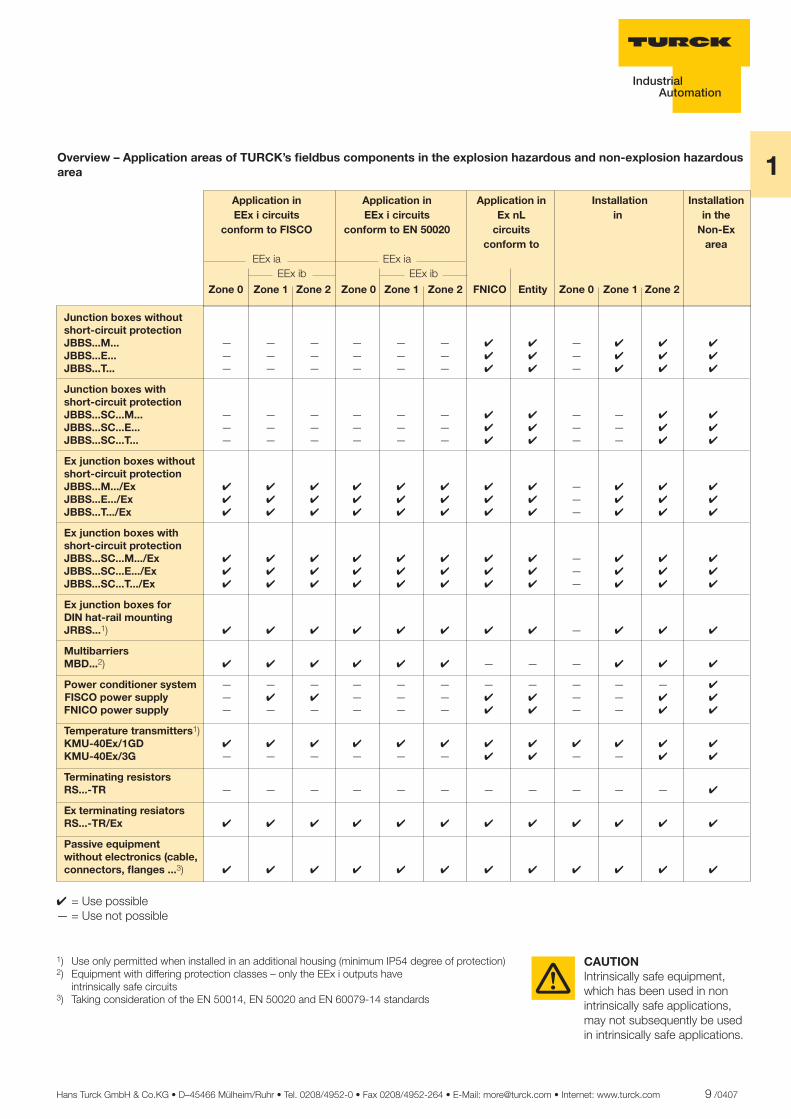
Overview – Application areas of TURCK’s fi eldbus components in the explosion hazardous and non-explosion hazardous area
Zone 0 Zone 1 Zone 2Zone 0 Zone 1 Zone 2 Zone 0 Zone 1 Zone 2
Application in Application in Application in Installation Installation EEx i circuits EEx i circuits Ex nL in in the conform to FISCO conform to EN 50020 circuits Non-Ex conform to area EEx ia EEx ia EEx ib EEx ib
Junction boxes without short-circuit protection JBBS...M... — — — — — — ✔ ✔ — ✔ ✔ ✔ JBBS...E... — — — — — — ✔ ✔ — ✔ ✔ ✔ JBBS...T... — — — — — — ✔ ✔ — ✔ ✔ ✔
Junction boxes with short-circuit protection JBBS...SC...M... — — — — — — ✔ ✔ — — ✔ ✔ JBBS...SC...E... — — — — — — ✔ ✔ — — ✔ ✔ JBBS...SC...T... — — — — — — ✔ ✔ — — ✔ ✔
Ex junction boxes without short-circuit protection JBBS...M.../Ex ✔ ✔ ✔ ✔ ✔ ✔ ✔ ✔ — ✔ ✔ ✔ JBBS...E.../Ex ✔ ✔ ✔ ✔ ✔ ✔ ✔ ✔ — ✔ ✔ ✔ JBBS...T.../Ex ✔ ✔ ✔ ✔ ✔ ✔ ✔ ✔ — ✔ ✔ ✔
Ex junction boxes with short-circuit protection JBBS...SC...M.../Ex ✔ ✔ ✔ ✔ ✔ ✔ ✔ ✔ — ✔ ✔ ✔ JBBS...SC...E.../Ex ✔ ✔ ✔ ✔ ✔ ✔ ✔ ✔ — ✔ ✔ ✔ JBBS...SC...T.../Ex ✔ ✔ ✔ ✔ ✔ ✔ ✔ ✔ — ✔ ✔ ✔
Ex junction boxes for DIN hat-rail mounting JRBS...1) ✔ ✔ ✔ ✔ ✔ ✔ ✔ ✔ — ✔ ✔ ✔
Multibarriers MBD...2) ✔ ✔ ✔ ✔ ✔ ✔ — — — ✔ ✔ ✔
Power conditioner system — — — — — — — — — — — ✔ FISCO power supply — ✔ ✔ — — — ✔ ✔ — — ✔ ✔ FNICO power supply — — — — — — ✔ ✔ — — ✔ ✔
Temperature transmitters1) KMU-40Ex/1GD ✔ ✔ ✔ ✔ ✔ ✔ ✔ ✔ ✔ ✔ ✔ ✔ KMU-40Ex/3G — — — — — — ✔ ✔ — — ✔ ✔
Terminating resistors RS...-TR — — — — — — — — — — — ✔
Ex terminating resiators RS...-TR/Ex ✔ ✔ ✔ ✔ ✔ ✔ ✔ ✔ ✔ ✔ ✔ ✔
Passive equipment without electronics (cable, connectors, fl anges ...3) ✔ ✔ ✔ ✔ ✔ ✔ ✔ ✔ ✔ ✔ ✔ ✔
✔ = Use possible — = Use not possible
1) Use only permitted when installed in an additional housing (minimum IP54 degree of protection) 2) Equipment with differing protection classes – only the EEx i outputs have intrinsically safe circuits3) Taking consideration of the EN 50014, EN 50020 and EN 60079-14 standards
FNICO Entity
CAUTION Intrinsically safe equipment, which has been used in non intrinsically safe applications, may not subsequently be used in intrinsically safe applications.
10 /0407 Hans Turck GmbH & Co.KG • D–45466 Mülheim/Ruhr • Tel. 0208/4952-0 • Fax 0208/4952-264 • E-Mail: [email protected] • Internet: www.turck.com
ñ Edition:
Hans Turck GmbH & Co.KG ñ D-45472 Mülheim an der Ruhr ñ Witzlebenstraße 7 ñ Tel. 0208 4952-0 ñ Fax 0208 4952-264 ñ [email protected] ñ www.turck.com
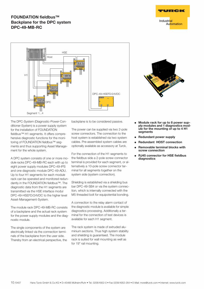
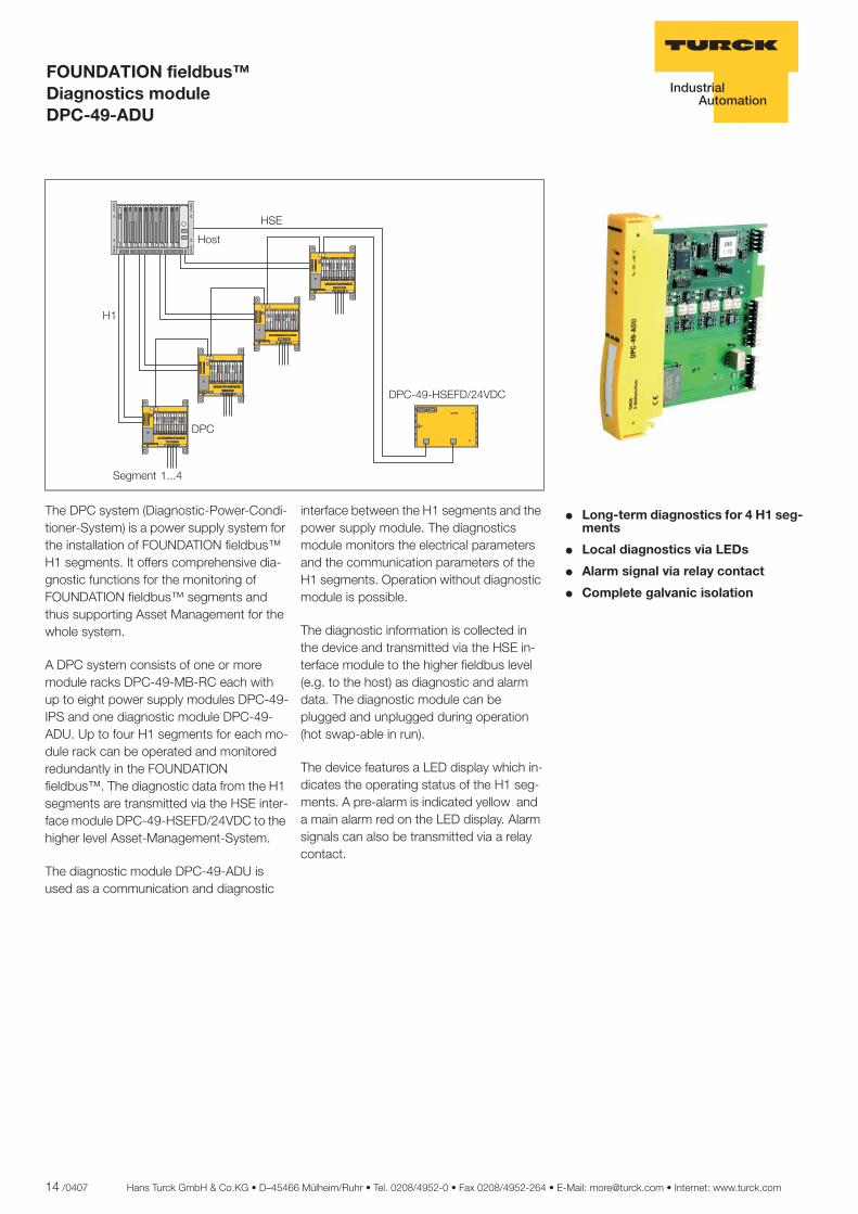
FOUNDATION fieldbus™ Backplane for the DPC system DPC-49-MB-RC
� Module rack for up to 8 power sup-ply modules and 1 diagnostics mod-ule for the mounting of up to 4 H1 segments
� Redundant power supply
� Redundant HOST connection
� Removable terminal blocks with screw connection
� RJ45 connector for HSE fieldbus diagnostics
The DPC-System (Diagnostic-Power-Con-ditioner-System) is a power supply system for the installation of FOUNDATION fieldbus™ H1 segments. It offers compre-hensive diagnostic functions for the moni-toring of FOUNDATION fieldbus™ seg-ments and thus supporting Asset Manage-ment for the whole system.
A DPC system consists of one or more mo-dule racks DPC-49-MB-RC each with up to eight power supply modules DPC-49-IPS and one diagnostic module DPC-49-ADU. Up to four H1 segments for each module rack can be operated and monitored redun-dantly in the FOUNDATION fieldbus™. The diagnostic data from the H1 segments are transmitted via the HSE interface modul DPC-49-HSEFD/24VDC to the higher level Asset-Management-System.
The module rack DPC-49-MB-RC consists of a backplane and the actual rack system for the power supply modules and the diag-nostic module.
The single components of the system are electrically linked via the connection termi-nals of the backplane from the user side. Thereby from an electrical perspective, the
backplane is to be considered passive.
The power can be supplied via two 2-pole screw connectors. The connection to the host system is established via two system cables. Pre-assembled system cables are optionally available as accessory at Turck.
For the connection of the H1 segments to the fieldbus side a 2-pole screw connector terminal is provided for each segment, or al-ternatively a 10-pole screw connector ter-minal for all segments together on the system side (system connection).
Shielding is established via a shielding bus bar DPC-49-SB4 or via the system connec-tion, which is internally connected with the M5 threaded bolt for equipotential bonding.
A connection to the relay alarm contact of the diagnostic module is avaliable for simple diagnostics processing. Additionally a ter-minal for the connection of test devices is available for each H1 segment.
The rack system is made of extruded alu-minium sections. Thus high system stability and shielding is guaranteed. The module rack is suited for wall mounting as well as for 19" rail mounting.
����
���
�� � �����
�����������������
��
��
���������������� �������������������������������� ���������������� ���������������� ���������������� ���������������� ���������������� ���������������� �������������������������������� ��������������������������������
���������������� �������������������������������� ���������������� ���������������� ���������������� ���������������� ���������������� ���������������� �������������������������������� ��������������������������������
���������������� �������������������������������� ���������������� ���������������� ���������������� ���������������� ���������������� ���������������� �������������������������������� ��������������������������������
���������������� �������������������������������� ���������������� ���������������� ���������������� ���������������� ���������������� ���������������� �������������������������������� ��������������������������������
Hans Turck GmbH & Co.KG • D–45466 Mülheim/Ruhr • Tel. 0208/4952-0 • Fax 0208/4952-264 • E-Mail: [email protected] • Internet: www.turck.com 11 /0407
2
ñ Edition:
Hans Turck GmbH & Co.KG ñ D-45472 Mülheim an der Ruhr ñ Witzlebenstraße 7 ñ Tel. 0208 4952-0 ñ Fax 0208 4952-264 ñ [email protected] ñ www.turck.com
FOUNDATION fieldbus™ Backplane for the DPC system DPC-49-MB-RC
Dimensions
���
���
���
��
��
��
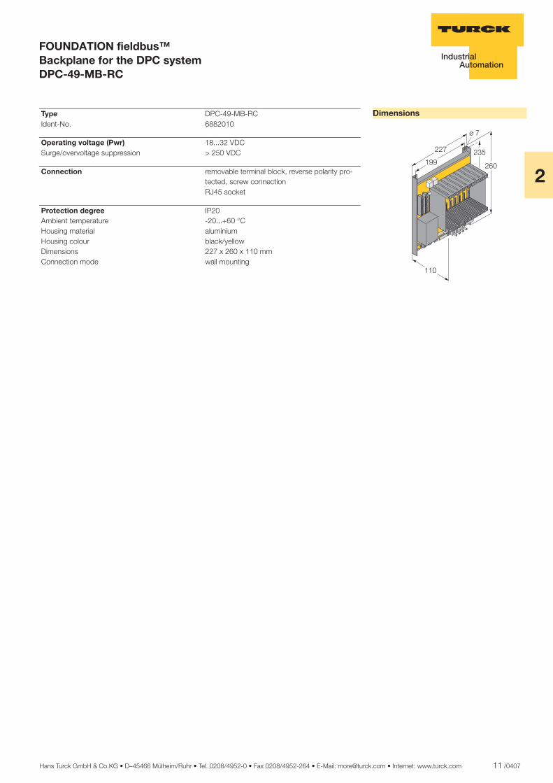
Type DPC-49-MB-RC Ident-No. 6882010
Operating voltage (Pwr) 18...32 VDC Surge/overvoltage suppression > 250 VDC
Connection removable terminal block, reverse polarity pro-tected, screw connection
RJ45 socket
Protection degree IP20 Ambient temperature -20...+60 °C Housing material aluminium Housing colour black/yellow Dimensions 227 x 260 x 110 mm Connection mode wall mounting
12 /0407 Hans Turck GmbH & Co.KG • D–45466 Mülheim/Ruhr • Tel. 0208/4952-0 • Fax 0208/4952-264 • E-Mail: [email protected] • Internet: www.turck.com
ñ Edition:
Hans Turck GmbH & Co.KG ñ D-45472 Mülheim an der Ruhr ñ Witzlebenstraße 7 ñ Tel. 0208 4952-0 ñ Fax 0208 4952-264 ñ [email protected] ñ www.turck.com
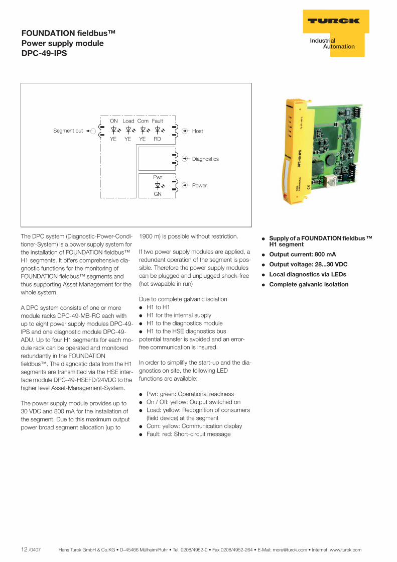
FOUNDATION fieldbus™ Power supply module DPC-49-IPS
� Supply of a FOUNDATION fieldbus ™ H1 segment
� Output current: 800 mA
� Output voltage: 28...30 VDC
� Local diagnostics via LEDs
� Complete galvanic isolation
The DPC system (Diagnostic-Power-Condi-tioner-System) is a power supply system for the installation of FOUNDATION fieldbus™ H1 segments. It offers comprehensive dia-gnostic functions for the monitoring of FOUNDATION fieldbus™ segments and thus supporting Asset Management for the whole system.
A DPC system consists of one or more module racks DPC-49-MB-RC each with up to eight power supply modules DPC-49-IPS and one diagnostic module DPC-49-ADU. Up to four H1 segments for each mo-dule rack can be operated and monitored redundantly in the FOUNDATION fieldbus™. The diagnostic data from the H1 segments are transmitted via the HSE inter-face module DPC-49-HSEFD/24VDC to the higher level Asset-Management-System.
The power supply module provides up to 30 VDC and 800 mA for the installation of the segment. Due to this maximum output power broad segment allocation (up to
1900 m) is possible without restriction.
If two power supply modules are applied, a redundant operation of the segment is pos-sible. Therefore the power supply modules can be plugged and unplugged shock-free (hot swapable in run)
Due to complete galvanic isolation� H1 to H1� H1 for the internal supply� H1 to the diagnostics module� H1 to the HSE diagnostics buspotential transfer is avoided and an error-free communication is insured.
In order to simplifiy the start-up and the dia-gnostics on site, the following LED functions are available:
� Pwr: green: Operational readiness� On / Off: yellow: Output switched on� Load: yellow: Recognition of consumers
(field device) at the segment� Com: yellow: Communication display� Fault: red: Short-circuit message
�����
������� ���
�� �� �� ��
�� ���� ��� ����
��
���
���� �����
Hans Turck GmbH & Co.KG • D–45466 Mülheim/Ruhr • Tel. 0208/4952-0 • Fax 0208/4952-264 • E-Mail: [email protected] • Internet: www.turck.com 13 /0407
2
ñ Edition:
Hans Turck GmbH & Co.KG ñ D-45472 Mülheim an der Ruhr ñ Witzlebenstraße 7 ñ Tel. 0208 4952-0 ñ Fax 0208 4952-264 ñ [email protected] ñ www.turck.com
FOUNDATION fieldbus™ Power supply module DPC-49-IPS
Dimensions
���
��
���
Type DPC-49-IPS Ident-No. 6882013
Supply voltage via the backplane Current consumption 0.8...1.7 A Galvanic isolation complete galvanic isolation, test voltage 500
VAC
Output circuits field Output current ð 800 mA Output voltage > 28 VDC Short-circuit protection ð 850 mA Efficiency 80 % Output circuits HOST Output current < 30 mA Output voltage 27 VDC
Indication Operational readiness 1 x green Output active 1 x yellow Output current 1 x yellow Short-circuit message 1 x red Bus communication 1 x yellow
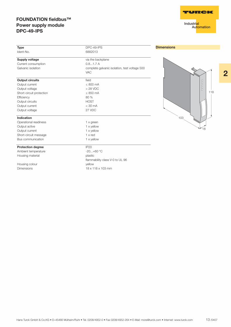
Protection degree IP20 Ambient temperature -20...+60 °C Housing material plastic flammability class V-0 to UL 96 Housing colour yellow Dimensions 18 x 118 x 103 mm
14 /0407 Hans Turck GmbH & Co.KG • D–45466 Mülheim/Ruhr • Tel. 0208/4952-0 • Fax 0208/4952-264 • E-Mail: [email protected] • Internet: www.turck.com
ñ Edition:
Hans Turck GmbH & Co.KG ñ D-45472 Mülheim an der Ruhr ñ Witzlebenstraße 7 ñ Tel. 0208 4952-0 ñ Fax 0208 4952-264 ñ [email protected] ñ www.turck.com
FOUNDATION fieldbus™ Diagnostics module DPC-49-ADU
� Long-term diagnostics for 4 H1 seg-ments
� Local diagnostics via LEDs
� Alarm signal via relay contact
� Complete galvanic isolation
The DPC system (Diagnostic-Power-Condi-tioner-System) is a power supply system for the installation of FOUNDATION fieldbus™ H1 segments. It offers comprehensive dia-gnostic functions for the monitoring of FOUNDATION fieldbus™ segments and thus supporting Asset Management for the whole system.
A DPC system consists of one or more module racks DPC-49-MB-RC each with up to eight power supply modules DPC-49-IPS and one diagnostic module DPC-49-ADU. Up to four H1 segments for each mo-dule rack can be operated and monitored redundantly in the FOUNDATION fieldbus™. The diagnostic data from the H1 segments are transmitted via the HSE inter-face module DPC-49-HSEFD/24VDC to the higher level Asset-Management-System.
The diagnostic module DPC-49-ADU is used as a communication and diagnostic
interface between the H1 segments and the power supply module. The diagnostics module monitors the electrical parameters and the communication parameters of the H1 segments. Operation without diagnostic module is possible.
The diagnostic information is collected in the device and transmitted via the HSE in-terface module to the higher fieldbus level (e.g. to the host) as diagnostic and alarm data. The diagnostic module can be plugged and unplugged during operation (hot swap-able in run).
The device features a LED display which in-dicates the operating status of the H1 seg-ments. A pre-alarm is indicated yellow and a main alarm red on the LED display. Alarm signals can also be transmitted via a relay contact.
����
���
�� � �����
�����������������
��
��
���������������� �������������������������������� ���������������� ���������������� ���������������� ���������������� ���������������� ���������������� �������������������������������� ��������������������������������
���������������� �������������������������������� ���������������� ���������������� ���������������� ���������������� ���������������� ���������������� �������������������������������� ��������������������������������
���������������� �������������������������������� ���������������� ���������������� ���������������� ���������������� ���������������� ���������������� �������������������������������� ��������������������������������
���������������� �������������������������������� ���������������� ���������������� ���������������� ���������������� ���������������� ���������������� �������������������������������� ��������������������������������
Hans Turck GmbH & Co.KG • D–45466 Mülheim/Ruhr • Tel. 0208/4952-0 • Fax 0208/4952-264 • E-Mail: [email protected] • Internet: www.turck.com 15 /0407
2
ñ Edition:
Hans Turck GmbH & Co.KG ñ D-45472 Mülheim an der Ruhr ñ Witzlebenstraße 7 ñ Tel. 0208 4952-0 ñ Fax 0208 4952-264 ñ [email protected] ñ www.turck.com
FOUNDATION fieldbus™ Diagnostics module DPC-49-ADU
Dimensions
���
��
���
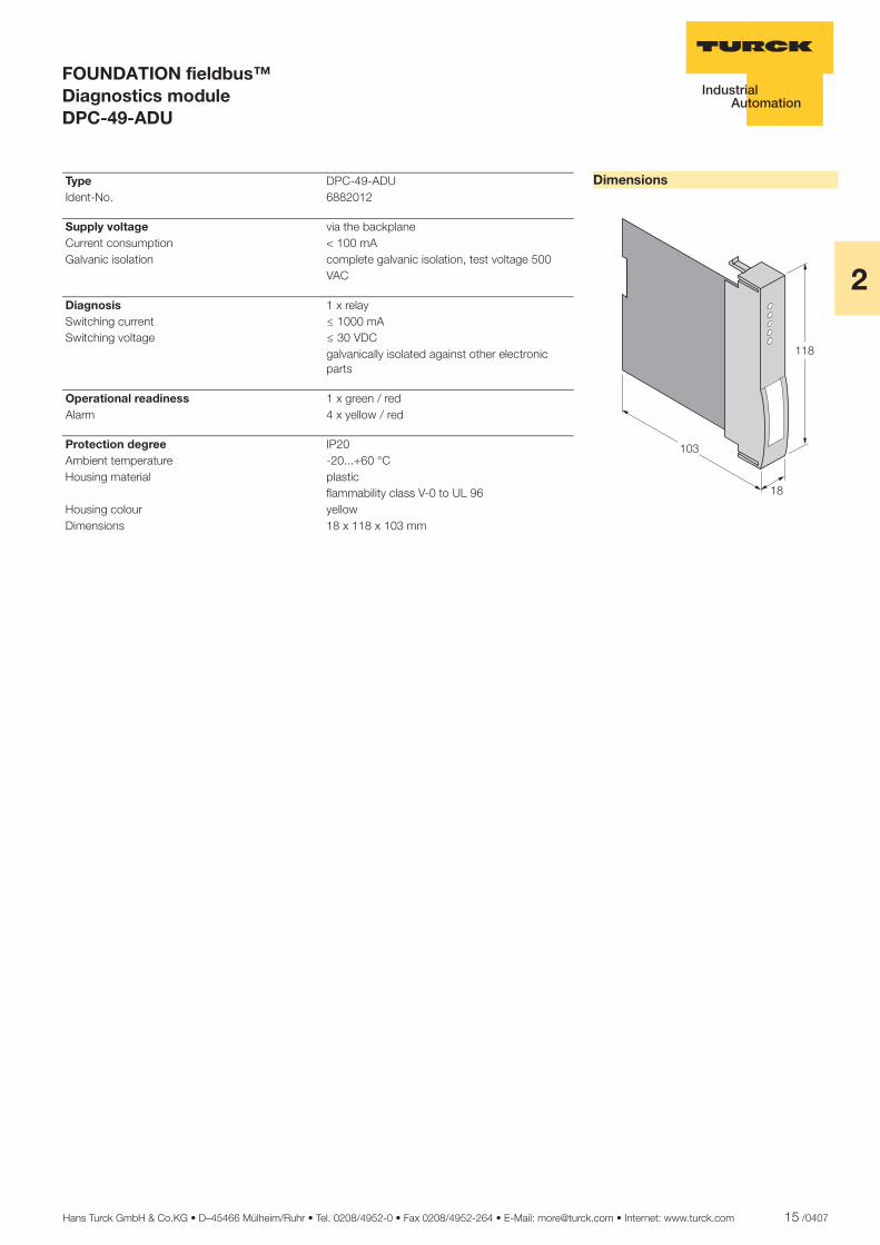
Type DPC-49-ADU Ident-No. 6882012
Supply voltage via the backplane Current consumption < 100 mA Galvanic isolation complete galvanic isolation, test voltage 500
VAC
Diagnosis 1 x relay Switching current ð 1000 mA Switching voltage ð 30 VDC galvanically isolated against other electronic
parts
Operational readiness 1 x green / red Alarm 4 x yellow / red
Protection degree IP20 Ambient temperature -20...+60 °C Housing material plastic flammability class V-0 to UL 96 Housing colour yellow Dimensions 18 x 118 x 103 mm
16 /0407 Hans Turck GmbH & Co.KG • D–45466 Mülheim/Ruhr • Tel. 0208/4952-0 • Fax 0208/4952-264 • E-Mail: [email protected] • Internet: www.turck.com
ñ Edition:
Hans Turck GmbH & Co.KG ñ D-45472 Mülheim an der Ruhr ñ Witzlebenstraße 7 ñ Tel. 0208 4952-0 ñ Fax 0208 4952-264 ñ [email protected] ñ www.turck.com
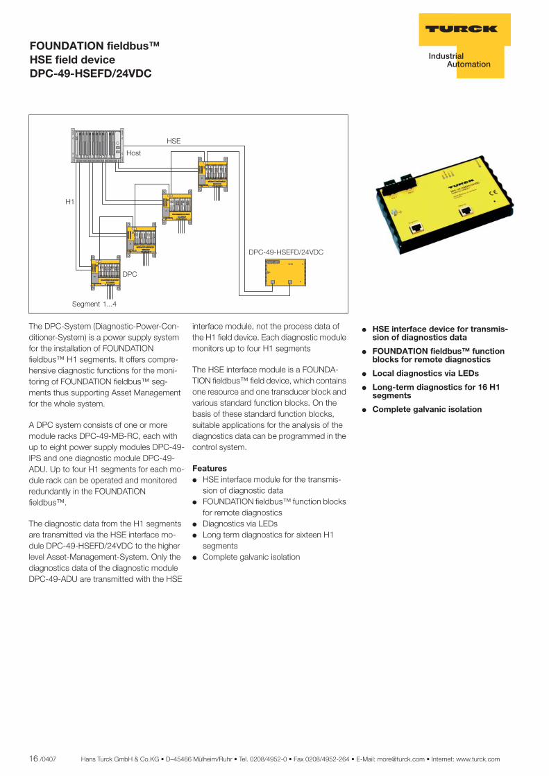
FOUNDATION fieldbus™ HSE field device DPC-49-HSEFD/24VDC
� HSE interface device for transmis-sion of diagnostics data
� FOUNDATION fieldbus™ function blocks for remote diagnostics
� Local diagnostics via LEDs
� Long-term diagnostics for 16 H1 segments
� Complete galvanic isolation
The DPC-System (Diagnostic-Power-Con-ditioner-System) is a power supply system for the installation of FOUNDATION fieldbus™ H1 segments. It offers compre-hensive diagnostic functions for the moni-toring of FOUNDATION fieldbus™ seg-ments thus supporting Asset Management for the whole system.
A DPC system consists of one or more module racks DPC-49-MB-RC, each with up to eight power supply modules DPC-49-IPS and one diagnostic module DPC-49-ADU. Up to four H1 segments for each mo-dule rack can be operated and monitored redundantly in the FOUNDATION fieldbus™.
The diagnostic data from the H1 segments are transmitted via the HSE interface mo-dule DPC-49-HSEFD/24VDC to the higher level Asset-Management-System. Only the diagnostics data of the diagnostic module DPC-49-ADU are transmitted with the HSE
interface module, not the process data of the H1 field device. Each diagnostic module monitors up to four H1 segments
The HSE interface module is a FOUNDA-TION fieldbus™ field device, which contains one resource and one transducer block and various standard function blocks. On the basis of these standard function blocks, suitable applications for the analysis of the diagnostics data can be programmed in the control system.
Features� HSE interface module for the transmis-
sion of diagnostic data� FOUNDATION fieldbus™ function blocks
for remote diagnostics� Diagnostics via LEDs� Long term diagnostics for sixteen H1
segments� Complete galvanic isolation
����
���
�� � �����
�����������������
��
��
���������������� �������������������������������� ���������������� ���������������� ���������������� ���������������� ���������������� ���������������� �������������������������������� ��������������������������������
���������������� �������������������������������� ���������������� ���������������� ���������������� ���������������� ���������������� ���������������� �������������������������������� ��������������������������������
���������������� �������������������������������� ���������������� ���������������� ���������������� ���������������� ���������������� ���������������� �������������������������������� ��������������������������������
���������������� �������������������������������� ���������������� ���������������� ���������������� ���������������� ���������������� ���������������� �������������������������������� ��������������������������������
Hans Turck GmbH & Co.KG • D–45466 Mülheim/Ruhr • Tel. 0208/4952-0 • Fax 0208/4952-264 • E-Mail: [email protected] • Internet: www.turck.com 17 /0407
2
ñ Edition:
Hans Turck GmbH & Co.KG ñ D-45472 Mülheim an der Ruhr ñ Witzlebenstraße 7 ñ Tel. 0208 4952-0 ñ Fax 0208 4952-264 ñ [email protected] ñ www.turck.com
FOUNDATION fieldbus™ HSE field device DPC-49-HSEFD/24VDC
Dimensions
��
�����
�� ��
�� ��
���
���
�� �� �� ��
���������� ���� ���
� � � �
�� !" #$�%���!&������������ �������
!'!((�)*+���,����-� �./� �� ,��0
���
���
��
���
���
��
���
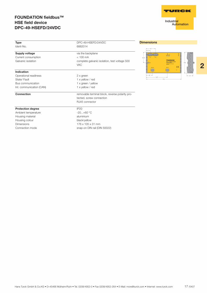
Type DPC-49-HSEFD/24VDC Ident-No. 6882014
Supply voltage via the backplane Current consumption < 100 mA Galvanic isolation complete galvanic isolation, test voltage 500
VAC
Indication Operational readiness 2 x green State/ Fault 1 x yellow / red Bus communication 1 x green / yellow Int. communication (CAN) 1 x yellow / red
Connection removable terminal block, reverse polarity pro-tected, screw connection
RJ45 connector
Protection degree IP20 Ambient temperature -20...+60 °C Housing material aluminium Housing colour black/yellow Dimensions 176 x 105 x 31 mm Connection mode snap-on DIN rail (DIN 50022)
18 /0407 Hans Turck GmbH & Co.KG • D–45466 Mülheim/Ruhr • Tel. 0208/4952-0 • Fax 0208/4952-264 • E-Mail: [email protected] • Internet: www.turck.com
ñ Edition:
Hans Turck GmbH & Co.KG ñ D-45472 Mülheim an der Ruhr ñ Witzlebenstraße 7 ñ Tel. 0208 4952-0 ñ Fax 0208 4952-264 ñ [email protected] ñ www.turck.com
FOUNDATION fieldbus™ Power conditioner, dual channel RPC49-205
� Supply of 2 H1-segments, connec-tion via removable screw terminals
� Aluminium rail housing
� Degree of protection IP20
� Connection of the housing potential via an M5 x 1 bolt
� Monitor function
� LEDs for indication of the operating status
� 2 x 500 mA output current
� Redundant power supply
� Short-circuit protected outputs
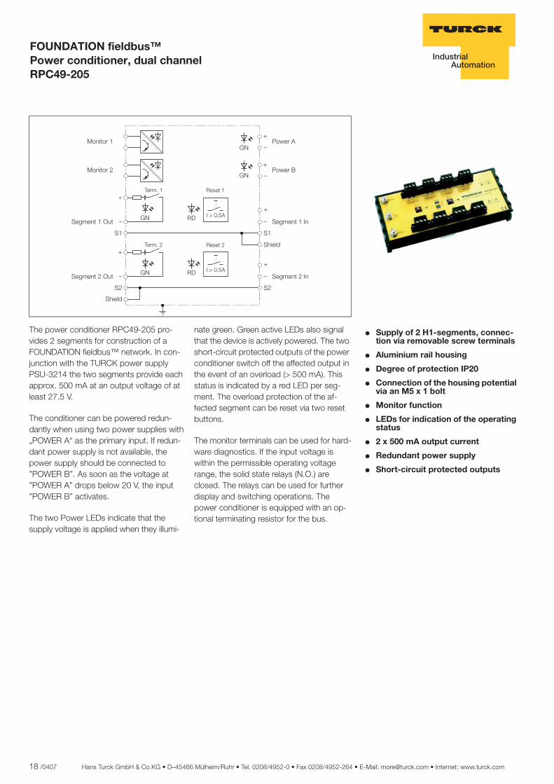
The power conditioner RPC49-205 pro-vides 2 segments for construction of a FOUNDATION fieldbus™ network. In con-junction with the TURCK power supply PSU-3214 the two segments provide each approx. 500 mA at an output voltage of at least 27.5 V.
The conditioner can be powered redun-dantly when using two power supplies with „POWER A“ as the primary input. If redun-dant power supply is not available, the power supply should be connected to ”POWER B”. As soon as the voltage at ”POWER A” drops below 20 V, the input ”POWER B” activates.
The two Power LEDs indicate that the supply voltage is applied when they illumi-
nate green. Green active LEDs also signal that the device is actively powered. The two short-circuit protected outputs of the power conditioner switch off the affected output in the event of an overload (> 500 mA). This status is indicated by a red LED per seg-ment. The overload protection of the af-fected segment can be reset via two reset buttons.
The monitor terminals can be used for hard-ware diagnostics. If the input voltage is within the permissible operating voltage range, the solid state relays (N.O.) are closed. The relays can be used for further display and switching operations. The power conditioner is equipped with an op-tional terminating resistor for the bus.
��������
��������
�
�
�������
������
�
��
������
��������������
�
�
�������
������
�
������
��������������
�
�
�
�
�
�
�!����
�!���"
�
�
�
�
��
��
��������� �
��������� �
�#��$%
�#��$%
��
Hans Turck GmbH & Co.KG • D–45466 Mülheim/Ruhr • Tel. 0208/4952-0 • Fax 0208/4952-264 • E-Mail: [email protected] • Internet: www.turck.com 19 /0407
2
ñ Edition:
Hans Turck GmbH & Co.KG ñ D-45472 Mülheim an der Ruhr ñ Witzlebenstraße 7 ñ Tel. 0208 4952-0 ñ Fax 0208 4952-264 ñ [email protected] ñ www.turck.com
FOUNDATION fieldbus™ Power conditioner, dual channel RPC49-205
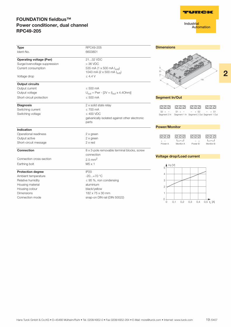
Dimensions
Segment In/Out
Power/Monitor
Voltage drop/Load current
������
������
����
��
� �
�
�����
��� ���
�����
���
�
�����
�������
����� ���
��
��
�����
�����
����
�
������
���
������
�����
�
��� !
" #$
�%��&
�'" $
((��)
����*�
������+
�
�����,
���
��
��
�� � � �� � ��������� ��������
� � �������������
� � �������������
� � � ������ ��� ��� ������ ��� ����
� ��� ����������
�
�
�
�
��� �� ���
�����
Type RPC49-205 Ident-No. 6603801
Operating voltage (Pwr) 21...32 VDC Surge/overvoltage suppression > 36 VDC Current consumption 535 mA (1 x 500 mA Iout))
1043 mA (2 x 500 mA Iout)) Voltage drop ð 4.4 V
Output circuits Output current ð 500 mA Output voltage Uout = Pwr - [2V + (Iout x 4.4Ohm)]
Short-circuit protection ð 500 mA
Diagnosis 2 x solid state relay Switching current ð 700 mA Switching voltage ð 400 VDC galvanically isolated against other electronic
parts
Indication Operational readiness 2 x green Output active 2 x green Short-circuit message 2 x red
Connection 8 x 3-pole removable terminal blocks, screw connection
Connection cross-section 2.5 mm2
Earthing bolt M5 x 1
Protection degree IP20 Ambient temperature -20...+70 °C Relative humidity ð 95 %, non condensing Housing material aluminium Housing colour black/yellow Dimensions 182 x 75 x 30 mm Connection mode snap-on DIN rail (DIN 50022)
20 /0407 Hans Turck GmbH & Co.KG • D–45466 Mülheim/Ruhr • Tel. 0208/4952-0 • Fax 0208/4952-264 • E-Mail: [email protected] • Internet: www.turck.com
ñ Edition:
Hans Turck GmbH & Co.KG ñ D-45472 Mülheim an der Ruhr ñ Witzlebenstraße 7 ñ Tel. 0208 4952-0 ñ Fax 0208 4952-264 ñ [email protected] ñ www.turck.com
Power supply Single-channel PSU-3214
� Output voltage 32 VDC
� Output current 1.4 A
� Safety extra low voltage SELV ac-cording to IEC/EN 60950
� Universal operating voltage (94...264 V AC)
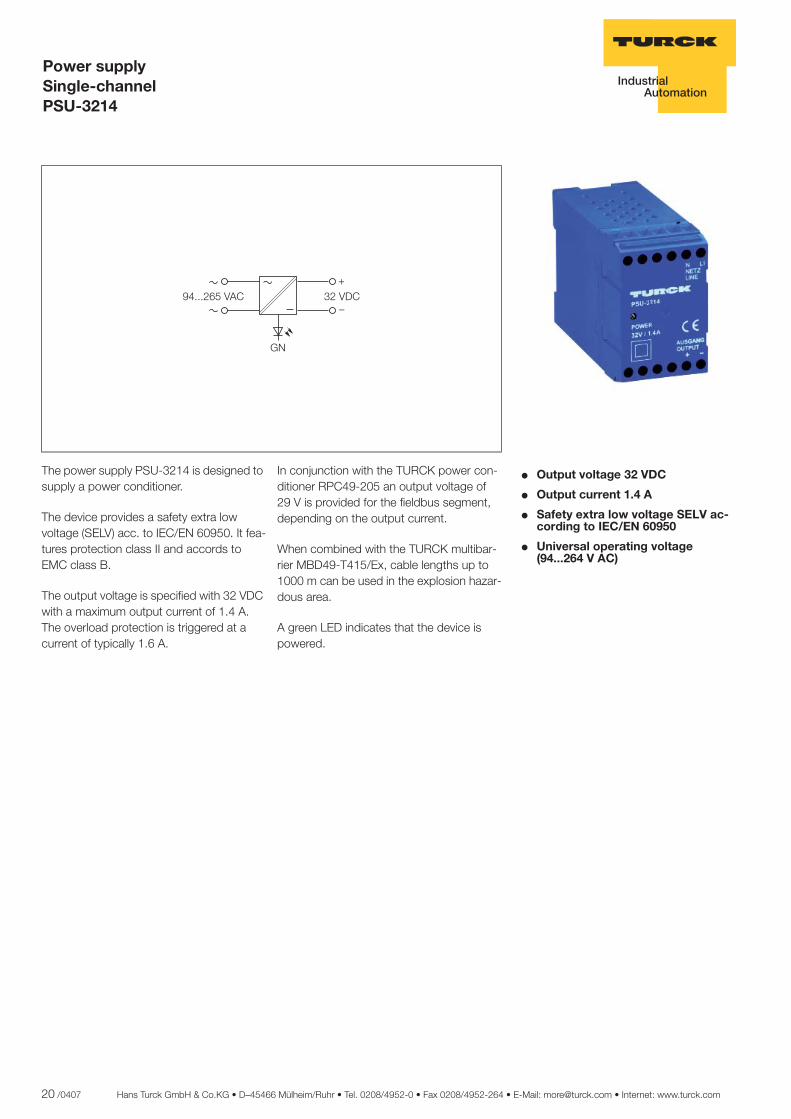
The power supply PSU-3214 is designed to supply a power conditioner.
The device provides a safety extra low voltage (SELV) acc. to IEC/EN 60950. It fea-tures protection class II and accords to EMC class B.
The output voltage is specified with 32 VDC with a maximum output current of 1.4 A. The overload protection is triggered at a current of typically 1.6 A.
In conjunction with the TURCK power con-ditioner RPC49-205 an output voltage of 29 V is provided for the fieldbus segment, depending on the output current.
When combined with the TURCK multibar-rier MBD49-T415/Ex, cable lengths up to 1000 m can be used in the explosion hazar-dous area.
A green LED indicates that the device is powered.
������
�
�� ����������
Hans Turck GmbH & Co.KG • D–45466 Mülheim/Ruhr • Tel. 0208/4952-0 • Fax 0208/4952-264 • E-Mail: [email protected] • Internet: www.turck.com 21 /0407
2
ñ Edition:
Hans Turck GmbH & Co.KG ñ D-45472 Mülheim an der Ruhr ñ Witzlebenstraße 7 ñ Tel. 0208 4952-0 ñ Fax 0208 4952-264 ñ [email protected] ñ www.turck.com
Power supply Single-channel PSU-3214
Dimensions
Output curve
������
�
��
� �
���
�����
�������
�����
���
�� ��
��
��
���
��
�
�
�
��
��
��
��
��
�
�� �� ��� �����
��
��
Type PSU-3214 Ident-No. 7545024
Operating voltage (Pwr) 94...265 VAC Mains frequency 47...63 Hz Current consumption 0.6 A at 230 VAC / 1.1 A at 120 VAC Starting current inrush I2t < 2.8 A2s Galvanic isolation Input circuit to output circuit and supply
voltage for 250 Vrms; test voltage 3 kVrms
Output circuits Output current ð 1400 mA Output voltage 32 VDC (± 3 %) Residual ripple ð 50 mVss
Short-circuit protection ð 1600 mA Efficiency 89 % Derating 2.5 %/K (from +60 °C)
Indication Operational readiness 1 x green
Connection flat terminals with self-lifting pressure plates Connection cross-section 1 x 2.5 mm2 / 2 x 2.5 mm2
Protection degree IP20 Ambient temperature -10...+70 °C Housing material plastic Housing colour blue Dimensions 45 x 72 x 105 mm Connection mode snap-on DIN rail (DIN 50022)
22 /0407 Hans Turck GmbH & Co.KG • D–45466 Mülheim/Ruhr • Tel. 0208/4952-0 • Fax 0208/4952-264 • E-Mail: [email protected] • Internet: www.turck.com
ñ Edition:
Hans Turck GmbH & Co.KG ñ D-45472 Mülheim an der Ruhr ñ Witzlebenstraße 7 ñ Tel. 0208 4952-0 ñ Fax 0208 4952-264 ñ [email protected] ñ www.turck.com
FOUNDATION fieldbus™ FISCO Power Supply RPC49-10120EX
� FISCO compliance according to IEC TS 60079-27
� Protection type: [EEx ib] IIC
� Mounting in zone 2 possible
� FISCO power supply for FOUNDA-TION fieldbus™
� Output current: 120 mA
� Fieldbus - repeater
� Installation in zone 2
� Temperature range: -40...+70°C
The RPC49-10120EX fieldbus power supply repeats the fieldbus signal from a host control system to intrinsically safe fieldbus devices in a zone 1 hazardous area. Complying with the IEC 60079-27 FISCO technical specification, it is capable of providing high levels of current in the ha-zardous area, while maintaining the benefits of a true intrinsically safe circuit throughout the field network.
With the RPC49-10120EX an integrated transfer between the host and the field con-nections can be implemented, which ena-bles a parallel connection of several devices in the fieldbus and accordingly allows a higher number of field devices in the seg-ment.
Designed to operate in harsh environments, and suitable for installation in zone 2 explo-sion hazardous areas, the TURCK power supply RPC49-10120EX expands the boundaries for fieldbus architecture.
The RPC49-10120EX delivers up to 120 mA, powering field devices in Gas Group IIC environments. The DIN-rail mounted unit is designed to exploit the very latest advances in explosion protection practice contained in the FISCO (Fieldbus Intrinsically Safe Concept) technical specifi-cations, allowing users to reap the full po-tential of digital fieldbus communication without artificial constraints.
Offering unparalleled performance and flexi-bility, the TURCK supply RPC49-10120EX makes it easy to design, install and maintain IEC 61158-2 fieldbus networks conforming to the 31.25 kbits/s physical layer specifica-tion. Compatibility with the TURCK range of wiring components and accessories en-sures high reliability, low installation cost and high operational safety.
The supply to the host can be selected by a switch; accordingly no additional power supplies are required.
���
������� �����
���
���������
��������� �
���
���
���
���
���
��
��

Hans Turck GmbH & Co.KG • D–45466 Mülheim/Ruhr • Tel. 0208/4952-0 • Fax 0208/4952-264 • E-Mail: [email protected] • Internet: www.turck.com 23 /0407
2
ñ Edition:
Hans Turck GmbH & Co.KG ñ D-45472 Mülheim an der Ruhr ñ Witzlebenstraße 7 ñ Tel. 0208 4952-0 ñ Fax 0208 4952-264 ñ [email protected] ñ www.turck.com
FOUNDATION fieldbus™ FISCO Power Supply RPC49-10120EX
Dimensions
����
����� �� �������
������������������
��������������
��
��������
��
��� �����������
�� ����
Type RPC49-10120EX Ident-No. 6604157
Operating voltage (Pwr) 19.2...30 VDC Current consumption 235 mA (typ.) 330 mA (max.) at 20 V
190 mA (typ.) 265 mA (max.) at 24 V155 mA (typ.) 215 mA (max.) at 30 V
Galvanic isolation input circuit to output circuit and supply voltage for 250 Vrms
Output circuits Output current ð 120 mA Output voltage 12.4 VDC Short-circuit protection ð 140 mA
Indication Operational readiness 1 x green Short-circuit message 1 x red Bus communication 2 x yellow
Ex approval acc. to conformity certificate BASEEFA 05 ATEX 0127 FISCO parameter acc. to IEC TS 60079-27 Max. output voltage Uo ð 14 V
Max. output current Io ð 180 mA
Max. output power Po ð 2520 mW
External inductances/capacitances Lo/Co 300 µH / 0.2 µF
Marking of the device É II (2) GD [EEx ib] IIC É II 3 G EEx nA II T4 X FISCO Power Supply
Connection 3 x 3-pole removable terminal blocks, reverse polarity protected, screw connection or tension spring
Connection cross-section 2.5 mm2
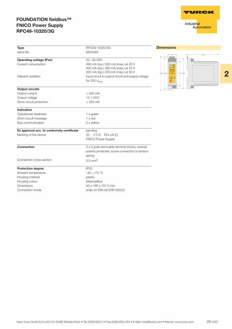
Protection degree IP20 Ambient temperature -40...+70 °C Housing material plastic Housing colour black/yellow Dimensions 42 x 166 x 137.5 mm Connection mode snap-on DIN rail (DIN 50022)

24 /0407 Hans Turck GmbH & Co.KG • D–45466 Mülheim/Ruhr • Tel. 0208/4952-0 • Fax 0208/4952-264 • E-Mail: [email protected] • Internet: www.turck.com
ñ Edition:
Hans Turck GmbH & Co.KG ñ D-45472 Mülheim an der Ruhr ñ Witzlebenstraße 7 ñ Tel. 0208 4952-0 ñ Fax 0208 4952-264 ñ [email protected] ñ www.turck.com
FOUNDATION fieldbus™ FISCO Power Supply RPC49-10265EX
� FISCO compliance according to IEC TS 60079-27
� Protection type: [EEx ib] IIB
� Mounting in zone 2 possible
� FISCO power supply for FOUNDA-TION fieldbus™
� Output current: 265 mA
� Fieldbus - repeater
� Installation in zone 2
� Temperature range: -40...+70°C
The RPC49-10265EX fieldbus power supply repeats the fieldbus signal from a host control system to intrinsically safe fieldbus devices in a zone 1 hazardous area. Complying with the IEC 60079-27 FISCO technical specification, it is capable of providing high levels of current in the hazardous area, while maintaining the be-nefits of a true intrinsically safe circuit throu-ghout the field network.
With the RPC49-10265EX an integrated transfer between the host and the field con-nections can be implemented, which ena-bles a parallel connection of several devices in the fieldbus and accordingly allows a higher number of field devices in the seg-ment.
Designed to operate in harsh environments, and suitable for installation in zone 2 explo-sion hazardous areas, the TURCK power supply RPC49-10265EX expands the boundaries for fieldbus architecture.
The RPC49-10265EX delivers up to 265 mA powering field devices in Gas Group IIB environments. The DIN-rail mounted unit is designed to exploit the very latest advances in explosion protection practice contained in the FISCO (Fieldbus Intrinsically Safe Concept) technical specifi-cations, allowing users to reap the full po-tential of digital fieldbus communication without artificial constraints.
Offering unparalleled performance and flexi-bility, the TURCK supply RPC49-10265EX makes it easy to design, install and maintain IEC 61158-2 fieldbus networks conforming to the 31.25 kbits/s physical layer specifica-tion. Compatibility with the TURCK range of wiring components and accessories en-sures high reliability, low installation cost and high operational safety.
The supply to the host can be selected by a switch; accordingly no additional power supplies are required.
���
������� �����
���
���������
��������� �
���
���
���
���
���
��
��
Hans Turck GmbH & Co.KG • D–45466 Mülheim/Ruhr • Tel. 0208/4952-0 • Fax 0208/4952-264 • E-Mail: [email protected] • Internet: www.turck.com 25 /0407
2
ñ Edition:
Hans Turck GmbH & Co.KG ñ D-45472 Mülheim an der Ruhr ñ Witzlebenstraße 7 ñ Tel. 0208 4952-0 ñ Fax 0208 4952-264 ñ [email protected] ñ www.turck.com
FOUNDATION fieldbus™ FISCO Power Supply RPC49-10265EX
Dimensions
����
����� ����������
������������������
��������������
��
��������
�
��� �����������
�� ����
Type RPC49-10265EX Ident-No. 6604158
Operating voltage (Pwr) 19.2...30 VDC Current consumption 380 mA (typ.) 495 mA (max.) at 20 V
315 mA (typ.) 410 mA (max.) at 24 V255 mA (typ.) 330 mA (max.) at 30 V
Galvanic isolation input circuit to output circuit and supply voltage for 250 Vrms
Output circuits Output current ð 265 mA Output voltage 13.1 VDC Short-circuit protection ð 285 mA
Indication Operational readiness 1 x green Short-circuit message 1 x red Bus communication 2 x yellow
Ex approval acc. to conformity certificate BASEEFA 05 ATEX 0127 FISCO parameter acc. to IEC TS 60079-27 Max. output voltage Uo ð 14.8 V
Max. output current Io ð 359 mA
Max. output power Po ð 5310 mW
External inductances/capacitances Lo/Co 550 µH / 0.5 µF
Marking of the device É II (2) GD [EEx ib] IIB É II 3 G EEx nA II T4 X FISCO Power Supply
Connection 3 x 3-pole removable terminal blocks, reverse polarity protected, screw connection or tension spring
Connection cross-section 2.5 mm2
Protection degree IP20 Ambient temperature -40...+70 °C Housing material plastic Housing colour black/yellow Dimensions 42 x 166 x 137.5 mm Connection mode snap-on DIN rail (DIN 50022)

26 /0407 Hans Turck GmbH & Co.KG • D–45466 Mülheim/Ruhr • Tel. 0208/4952-0 • Fax 0208/4952-264 • E-Mail: [email protected] • Internet: www.turck.com
ñ Edition:
Hans Turck GmbH & Co.KG ñ D-45472 Mülheim an der Ruhr ñ Witzlebenstraße 7 ñ Tel. 0208 4952-0 ñ Fax 0208 4952-264 ñ [email protected] ñ www.turck.com
FOUNDATION fieldbus™ FNICO Power Supply RPC49-10180/3G
� FNICO compliance according to IEC TS 60079-27
� Protection type: EEx nA[L] IIC
� Mounting in zone 2 possible
� FNICO power supply for FOUNDA-TION fieldbus™
� Output current: 180 mA
� Fieldbus - repeater
� Temperature range: -40...+70°C
The non incendive power supply type RPC49-10180/3G transfers the fieldbussignal from a host to approved FNICO and FISCO fieldbus devices in the explosion ha-zardous area of zone 2.
With the RPC49-10180/3G an integrated transfer between the host and the field con-nections can be implemented, which en-ables a parallel connection of several de-vices in the fieldbus and accordingly allows a higher number of field devices in the seg-ment.
Developed for use in harsh environments and suitable for installation in explosion ha-zardous areas of zone 2, the TURCK RPC49-10180/3G power supply extends the limits for fieldbus topologies.
The RPC49-10180/3G provides up to 180 mA and supplies power to field devices in the explosion hazardous area of explo-sion group IIC. The device is mounted on
DIN hat rails. It has been developed to uti-lize the latest developments of the FNICO (Fieldbus Non Incendive Concept) specifi-cation for explosion hazardous areas. Ac-cordingly, full exploitation of the potential in digital fieldbus communication is thus not subject to any system related limitations.
The RPC49-10180/3G enables a simple in-stallation, design and maintenance of fieldbus networks in accordance with IEC 61158-2 (Physical Layer with 31.25 kbps) due to its performance and flexibility. Furthermore, the compatibility to connec-tion components and accessories of the TURCK range guarantees a high level of re-liability, low installation costs and high ope-rating security.
The supply to the host can be selected by a switch; accordingly no additional power supplies are required.
���
�������� �����
���
����������
������������
���
���
���
��
��!
�
��

Hans Turck GmbH & Co.KG • D–45466 Mülheim/Ruhr • Tel. 0208/4952-0 • Fax 0208/4952-264 • E-Mail: [email protected] • Internet: www.turck.com 27 /0407
2
ñ Edition:
Hans Turck GmbH & Co.KG ñ D-45472 Mülheim an der Ruhr ñ Witzlebenstraße 7 ñ Tel. 0208 4952-0 ñ Fax 0208 4952-264 ñ [email protected] ñ www.turck.com
FOUNDATION fieldbus™ FNICO Power Supply RPC49-10180/3G
Dimensions
����
����� �� ��������
������������������
��������������
��
��������
�
��� �����������
�� ����
Type RPC49-10180/3G Ident-No. 6604484
Operating voltage (Pwr) 20...30 VDC Current consumption 300 mA (typ.) 330 mA (max.) at 20 V
250 mA (typ.) 280 mA (max.) at 24 V210 mA (typ.) 235 mA (max.) at 30 V
Galvanic isolation input circuit to output circuit and supply voltage for 250 Vrms
Output circuits Output current ð 180 mA Output voltage 12.4 VDC Short-circuit protection ð 180 mA
Indication Operational readiness 1 x green Short-circuit message 1 x red Bus communication 2 x yellow
Ex approval acc. to conformity certificate pending Marking of the device É II 3 G EEx nA [L] FNICO Power Supply
Connection 3 x 3-pole removable terminal blocks, reverse polarity protected, screw connection or tension spring
Connection cross-section 2.5 mm2
Protection degree IP20 Ambient temperature -40...+70 °C Housing material plastic Housing colour black/yellow Dimensions 42 x 166 x 137.5 mm Connection mode snap-on DIN rail (DIN 50022)
28 /0407 Hans Turck GmbH & Co.KG • D–45466 Mülheim/Ruhr • Tel. 0208/4952-0 • Fax 0208/4952-264 • E-Mail: [email protected] • Internet: www.turck.com
ñ Edition:
Hans Turck GmbH & Co.KG ñ D-45472 Mülheim an der Ruhr ñ Witzlebenstraße 7 ñ Tel. 0208 4952-0 ñ Fax 0208 4952-264 ñ [email protected] ñ www.turck.com
FOUNDATION fieldbus™ FNICO Power Supply RPC49-10320/3G
� FNICO compliance according to IEC TS 60079-27
� Protection type: EEx nA[L] IIB
� Mounting in zone 2 possible
� FNICO power supply for FOUNDA-TION fieldbus™
� Output current: 320 mA
� Fieldbus - repeater
� Temperature range: -40...+70°C
The non incendive power supply type RPC49-10320/3G transfers the fieldbus signal from a host to approved FNICO and FISCO fieldbus devices in the explosion ha-zardous area of zone 2.
With the RPC49-10320/3G an integrated transfer between the host and the field con-nections can be implemented, which en-ables a parallel connection of several de-vices in the fieldbus and accordingly allows a higher number of field devices in the seg-ment.
Developed for use in harsh environments and suitable for installation in explosion ha-zardous areas of zone 2, the TURCK RPC49-10320/3G power supply extends the limits for fieldbus topologies.
The RPC49-10320/3G provides up to 320 mA and supplies power to field devices in the explosion hazardous area of explosion group IIC. The device is mounted on DIN
hat rails. It has been developed to utilize the latest developments of the FNICO (Fieldbus Non Incendive Concept) specification for explosion hazardous areas. Accordingly, full exploitation of the potential in digital fieldbus communication is thus not subject to any system related limitations.
The RPC49-10320/3G enables a simple in-stallation, design and maintenance of fieldbus networks in accordance with IEC 61158-2 (Physical Layer with 31.25 kbps) due to its performance and flexibility. Furthermore, the compatibility to connec-tion components and accessories of the TURCK range guarantees a high level of re-liability, low installation costs and high op-erating security.
The supply to the host can be selected by a switch; accordingly no additional power supplies are required.
���
�������� �����
���
����������
������������
���
���
���
��
��!
�
��
Hans Turck GmbH & Co.KG • D–45466 Mülheim/Ruhr • Tel. 0208/4952-0 • Fax 0208/4952-264 • E-Mail: [email protected] • Internet: www.turck.com 29 /0407
2
ñ Edition:
Hans Turck GmbH & Co.KG ñ D-45472 Mülheim an der Ruhr ñ Witzlebenstraße 7 ñ Tel. 0208 4952-0 ñ Fax 0208 4952-264 ñ [email protected] ñ www.turck.com
FOUNDATION fieldbus™ FNICO Power Supply RPC49-10320/3G
Dimensions
����
����� �� ��������
������������������
��������������
��
��������
�
��� �����������
�� ����
Type RPC49-10320/3G Ident-No. 6604483
Operating voltage (Pwr) 20...30 VDC Current consumption 490 mA (typ.) 550 mA (max.) at 20 V
400 mA (typ.) 460 mA (max.) at 24 V320 mA (typ.) 370 mA (max.) at 30 V
Galvanic isolation input circuit to output circuit and supply voltage for 250 Vrms
Output circuits Output current ð 320 mA Output voltage 13.1 VDC Short-circuit protection ð 320 mA
Indication Operational readiness 1 x green Short-circuit message 1 x red Bus communication 2 x yellow
Ex approval acc. to conformity certificate pending Marking of the device É II 3 G EEx nA [L] FNICO Power Supply
Connection 3 x 3-pole removable terminal blocks, reverse polarity protected, screw connection or tension spring
Connection cross-section 2.5 mm2
Protection degree IP20 Ambient temperature -40...+70 °C Housing material plastic Housing colour black/yellow Dimensions 42 x 166 x 137.5 mm Connection mode snap-on DIN rail (DIN 50022)

30 /0407 Hans Turck GmbH & Co.KG • D–45466 Mülheim/Ruhr • Tel. 0208/4952-0 • Fax 0208/4952-264 • E-Mail: [email protected] • Internet: www.turck.com
FOUNDATION fi eldbus™
Hans Turck GmbH & Co.KG • D–45466 Mülheim/Ruhr • Tel. 0208/4952-0 • Fax 0208/4952-264 • E-Mail: [email protected] • Internet: www.turck.com 31 /0407
3
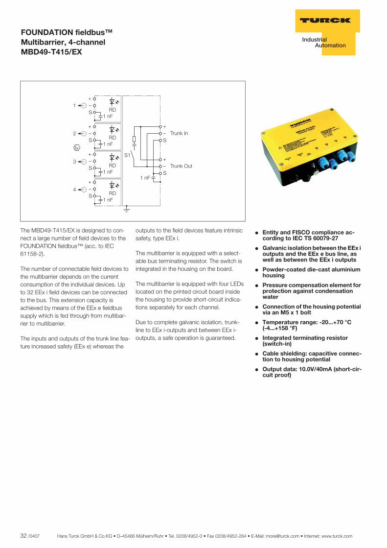
The operating principle of the MBD49-T415/Ex multibarrier is physically based on IEC 61158-2. The use of multibarriers increases the number of fi eldbus stations in the FOUNDATION fi eldbus™ network to a maximum of 32 fi eld devices.
This high number of stations is achieved by enhanced safety of the fi eldbus supply which can be looped through from multi-barrier to multibarrier. The fi eldbus stations in zone 0 are supplied with power via the four intrinsically safe outputs of each multibarrier device.
User benefi tsThe user can expect substantial cost ad-vantages due to the possibility of cascad-ing the multibarriers in a single segment in the explosion hazardous area, thus fully exploiting the entire function range of the bus systems.
All fi eldbus devices can be operated in a single fi eldbus segment in the explo-sion hazard area. Thus, the costs for an additional bus coupler or a segment card as well as their integration and parameter defi nition are eliminated. An additional trunk line and the wiring material is also spared.
The supply of power to the multibarriers is implemented via the bus which means that an additional power cable is not required.
Installation in the explosion hazar-dous areaThe area of application to ATEX is II 2 (1 GD) G EEx m e [ia] IIC T4.
Due to its EEx e protection rating, the MBD49-T415/Ex multibarrier can be installed in zone 1 (II 2 G) according to 94/9/EC (ATEX 95a).
Use in explosion hazardous areas with explosion protection group IIC – in con-junction with temperature class T4 – is the standard in the process industry.
Within zone 1, the MBD49-T415/Ex is connected via a cable and connections with enhanced safety (EEx e) to the main line (trunk line) of a fi eldbus conform to IEC 61158-2. This offers the advantage that the connection to the bus can be implemented using a loop isolator without EX approval, but with a suffi ciently high capacity.
Intrinsic safety and galvanic isolation between all outputsFor safety reasons, galvanic isolation of signals plays a decisive role in the Ex area. The multibarrier provides four intrinsically safe and galvanically isolated outputs. The complete galvanic isolation exists between the main bus cable (trunk line) and the out-put circuits as well as between all of the four individual output circuits.
Galvanic isolation of intrinsically safe cir-cuits, as demanded by the industry,particularly for zone 0, is thus provided.
Potential transfers and potential equaliza-tion currents are thus reduced and safe data transmission is guaranteed.
Operational safetyOperational safety of the bus system must be guaranteed should a bus station fail or malfunction. The four outputs of the multibarrier each supply an output current of max. 40 mA.
If a short-circuit occurs on a fi eldbus sta-tion, the integrated short-circuit protection comes into play. Only the affected output will be shut down, the main line and the other outputs of the fi eldbus segment remain operational. The short-circuit is indicated for each channel by a red LED inside the housing.
Industrially suitable housingIndustrial environmental conditions are fre-quently harsh and aggressive. Therefore, a housing suitable for these conditions is necessary. The enhanced IP66 degree of protection and the special housing mate-rial (die-cast aluminium) – in conjunction with the encapsulated module electronics – meet these demands and provide a high level of operational safety. Direct installa-tion of a multibarrier in the system is thus unproblematic.
The EEx e cable glands guarantee safe and quick connection technology in conjunction with the high-quality cage clamps.
Shield terminals are capacitively connec-ted to the housing potential in order to divert possible interference voltages on the cable shield. The riveted ground bolt connects the housing to the main poten-tial equalisation.
Functions which supplement the standard• FISCO conformity The FISCO model has been developed for the supply of power to fi eldbus stations in the Ex area by the PTB in cooperation with renowned manufacturers. FISCO stands for Fieldbus Intrinsically Safe Concept. It is intended to simplify the verifi cation of intrinsic safety of fi eldbus systems. Intrinsically safe networks can be confi gured without highly complex calculations, and also expanded and operated without system certifi cation. The outputs of the multibarrier conform to the demands of an Ex current supply and also conform to FISCO.
• Switch-in terminating resistors Data transmission on bus cables is frequently infl uenced by signal refl ection, which can occur when the bus ends are not terminated. The fi eldbus must be provided with a terminating resistor at both ends in order to avoid signal refl ection. The multibarrier is provided with an integrated terminating resistor, which should be activated, when the multibarrier is connected as the last device on the main bus line (trunk line).
• Climatic compensation In regions subject to large temperature and air-humidity variations, it is possible that formation of condensation or a build-up of water within the housing is possible during operation. In order to avoid this, the multibarrier is fi tted on the cable connection end with a pressure equalisation element to avoid the build-up of condensation. The pressure equalisation element features IP67 degree of protection and guarantees continuous and reliable ventilation and venting of the multibarriers. The ePTFE diaphragm in the centre of the gland features a very high water ingress pressure and repels oil. Even 100 % of salt crystals are kept out.
FOUNDATION fi eldbus™Multibarrier MBD49-T415/Ex –Basics and application benefi ts
32 /0407 Hans Turck GmbH & Co.KG • D–45466 Mülheim/Ruhr • Tel. 0208/4952-0 • Fax 0208/4952-264 • E-Mail: [email protected] • Internet: www.turck.com
ñ Edition:
Hans Turck GmbH & Co.KG ñ D-45472 Mülheim an der Ruhr ñ Witzlebenstraße 7 ñ Tel. 0208 4952-0 ñ Fax 0208 4952-264 ñ [email protected] ñ www.turck.com
FOUNDATION fieldbus™ Multibarrier, 4-channel MBD49-T415/EX
� Entity and FISCO compliance ac-cording to IEC TS 60079-27
� Galvanic isolation between the EEx i outputs and the EEx e bus line, as well as between the EEx i outputs
� Powder-coated die-cast aluminium housing
� Pressure compensation element for protection against condensation water
� Connection of the housing potential via an M5 x 1 bolt
� Temperature range: -20...+70 °C (-4...+158 °F)
� Integrated terminating resistor (switch-in)
� Cable shielding: capacitive connec-tion to housing potential
� Output data: 10.0V/40mA (short-cir-cuit proof)
The MBD49-T415/EX is designed to con-nect a large number of field devices to the FOUNDATION fieldbus™ (acc. to IEC 61158-2).
The number of connectable field devices to the multibarrier depends on the current consumption of the individual devices. Up to 32 EEx i field devices can be connected to the bus. This extension capacity is achieved by means of the EEx e fieldbus supply which is fed through from multibar-rier to multibarrier.
The inputs and outputs of the trunk line fea-ture increased safety (EEx e) whereas the
outputs to the field devices feature intrinsic safety, type EEx i.
The multibarrier is equipped with a select-able bus terminating resistor. The switch is integrated in the housing on the board.
The multibarrier is equipped with four LEDs located on the printed circuit board inside the housing to provide short-circuit indica-tions separately for each channel.
Due to complete galvanic isolation, trunk-line to EEx i-outputs and between EEx i-outputs, a safe operation is guaranteed.
��
��
�
�
��
��
��
��
��� ���
��� �� ��
�
!
�
�� �
�� �
�� �
�� �
�� �
"�
"�
"�
"�
Hans Turck GmbH & Co.KG • D–45466 Mülheim/Ruhr • Tel. 0208/4952-0 • Fax 0208/4952-264 • E-Mail: [email protected] • Internet: www.turck.com 33 /0407
3
ñ Edition:
Hans Turck GmbH & Co.KG ñ D-45472 Mülheim an der Ruhr ñ Witzlebenstraße 7 ñ Tel. 0208 4952-0 ñ Fax 0208 4952-264 ñ [email protected] ñ www.turck.com
FOUNDATION fieldbus™ Multibarrier, 4-channel MBD49-T415/EX
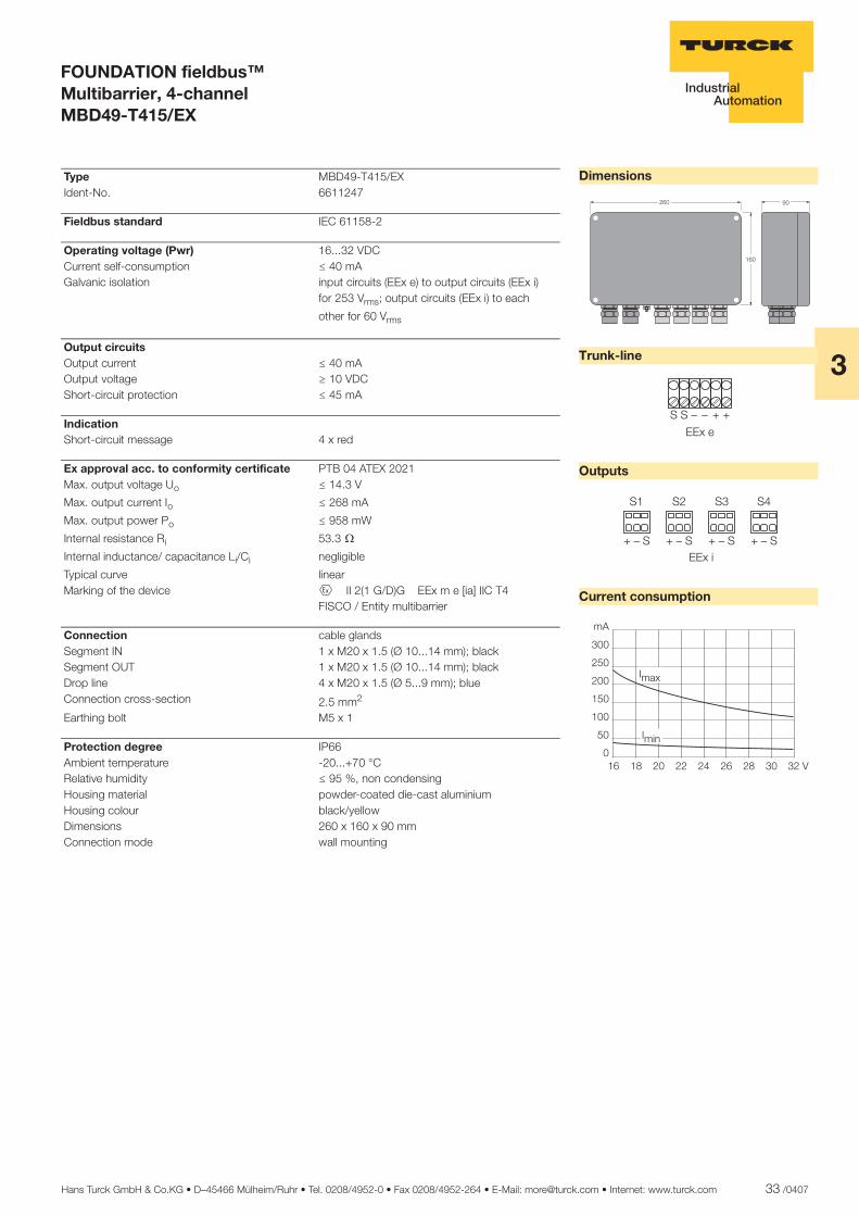
Dimensions
Trunk-line
Outputs
Current consumption
��
���
���
������ � �� � � �
�� ��
�� �� � ��
����� ����� ����� �����
�
��
��
���
���
���
���
���
�
� �� �� �� �� � �� ���
����
����
Type MBD49-T415/EX Ident-No. 6611247
Fieldbus standard IEC 61158-2
Operating voltage (Pwr) 16...32 VDC Current self-consumption ð 40 mA Galvanic isolation input circuits (EEx e) to output circuits (EEx i)
for 253 Vrms; output circuits (EEx i) to each
other for 60 Vrms
Output circuits Output current ð 40 mA Output voltage ï 10 VDC Short-circuit protection ð 45 mA
Indication Short-circuit message 4 x red
Ex approval acc. to conformity certificate PTB 04 ATEX 2021 Max. output voltage Uo ð 14.3 V
Max. output current Io ð 268 mA
Max. output power Po ð 958 mW
Internal resistance Ri 53.3 ò
Internal inductance/ capacitance Li/Ci negligible
Typical curve linear Marking of the device É II 2(1 G/D)G EEx m e [ia] IIC T4 FISCO / Entity multibarrier
Connection cable glands Segment IN 1 x M20 x 1.5 (Ø 10...14 mm); black Segment OUT 1 x M20 x 1.5 (Ø 10...14 mm); black Drop line 4 x M20 x 1.5 (Ø 5...9 mm); blue Connection cross-section 2.5 mm2
Earthing bolt M5 x 1
Protection degree IP66 Ambient temperature -20...+70 °C Relative humidity ð 95 %, non condensing Housing material powder-coated die-cast aluminium Housing colour black/yellow Dimensions 260 x 160 x 90 mm Connection mode wall mounting
34 /0407 Hans Turck GmbH & Co.KG • D–45466 Mülheim/Ruhr • Tel. 0208/4952-0 • Fax 0208/4952-264 • E-Mail: [email protected] • Internet: www.turck.com
ñ Edition:
Hans Turck GmbH & Co.KG ñ D-45472 Mülheim an der Ruhr ñ Witzlebenstraße 7 ñ Tel. 0208 4952-0 ñ Fax 0208 4952-264 ñ [email protected] ñ www.turck.com
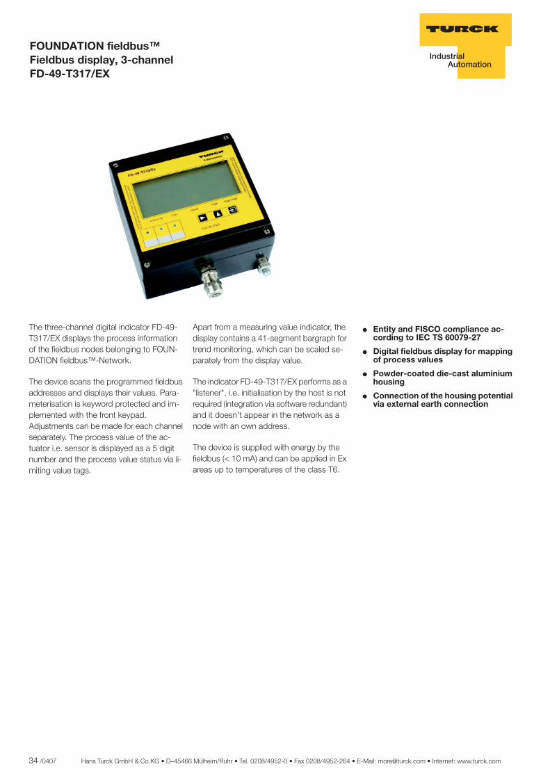
FOUNDATION fieldbus™ Fieldbus display, 3-channel FD-49-T317/EX
� Entity and FISCO compliance ac-cording to IEC TS 60079-27
� Digital fieldbus display for mapping of process values
� Powder-coated die-cast aluminium housing
� Connection of the housing potential via external earth connection
The three-channel digital indicator FD-49-T317/EX displays the process information of the fieldbus nodes belonging to FOUN-DATION fieldbus™-Network.
The device scans the programmed fieldbus addresses and displays their values. Para-meterisation is keyword protected and im-plemented with the front keypad. Adjustments can be made for each channel separately. The process value of the ac-tuator i.e. sensor is displayed as a 5 digit number and the process value status via li-miting value tags.
Apart from a measuring value indicator, the display contains a 41-segment bargraph for trend monitoring, which can be scaled se-parately from the display value.
The indicator FD-49-T317/EX performs as a "listener", i.e. initialisation by the host is not required (integration via software redundant) and it doesn't appear in the network as a node with an own address.
The device is supplied with energy by the fieldbus (< 10 mA) and can be applied in Ex areas up to temperatures of the class T6.
Hans Turck GmbH & Co.KG • D–45466 Mülheim/Ruhr • Tel. 0208/4952-0 • Fax 0208/4952-264 • E-Mail: [email protected] • Internet: www.turck.com 35 /0407
3
ñ Edition:
Hans Turck GmbH & Co.KG ñ D-45472 Mülheim an der Ruhr ñ Witzlebenstraße 7 ñ Tel. 0208 4952-0 ñ Fax 0208 4952-264 ñ [email protected] ñ www.turck.com
FOUNDATION fieldbus™ Fieldbus display, 3-channel FD-49-T317/EX
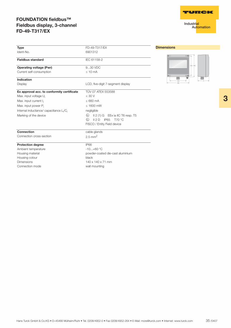
Dimensions
��� ��
��� ���
���
Type FD-49-T317/EX Ident-No. 6901312
Fieldbus standard IEC 61158-2
Operating voltage (Pwr) 9...30 VDC Current self-consumption ð 10 mA
Indication Display LCD, five-digit 7-segment display
Ex approval acc. to conformity certificate TÜV 07 ATEX 553588 Max. input voltage Ui ð 30 V
Max. input current Ii ð 660 mA
Max. input power Pi ð 1600 mW
Internal inductance/ capacitance Li/Ci negligible
Marking of the device É II 2 (1) G EEx ia IIC T6 resp. T5 É II 2 D G IP65 aaT70 °C FISCO / Entity Field device
Connection cable glands Connection cross-section 2.5 mm2
Protection degree IP66 Ambient temperature -10...+60 °C Housing material powder-coated die-cast aluminium Housing colour black Dimensions 140 x 140 x 71 mm Connection mode wall mounting
36 /0407 Hans Turck GmbH & Co.KG • D–45466 Mülheim/Ruhr • Tel. 0208/4952-0 • Fax 0208/4952-264 • E-Mail: [email protected] • Internet: www.turck.com
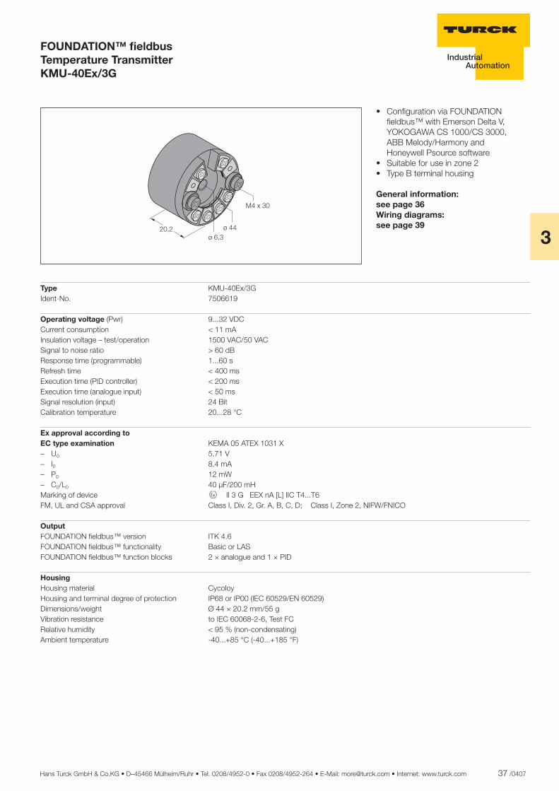
The KMU-40Ex/3G and KMU-40Ex/1GD transmitters are intended for connection to the FOUNDATION fi eldbus™. The unique conversion function enables automatic switch-over between both protocols. The bus connection is free of polarity consid-erations.
Applications:• Linear temperature measurements with resistance thermometers or thermocouples• Differential, average value or redundant temperature measurements with resis- tance thermometers or thermocouples
General technical data
Accuracy (general values)Input type Absolute accuracy Temperature coeffi cient– All ≤ ± 0.05 % of measured value ≤ ± 0.002 % of measured value/°C
Accuracy (fundamental values) Input type Fundamental accuracy Temperature coeffi cient – Pt100/Pt1000 ≤ ± 0.1 °C ≤ ± 0.002 °C/°C – Ni100 ≤ ± 0.15 °C ≤ ± 0.002 °C/°C – Cu10 ≤ ±1.3 °C ≤ ± 0.02 °C/°C – Linear resistor ≤ ± 0.05 Ω ≤ ± 0.002 Ω/°C – Voltage ≤ ± 10 µV ≤ ± 0.2 µV/°C – Thermocouple type: E, J, K, L, N, T, U ≤ ± 0.5 °C ≤ ± 0.010 °C/°C – Thermocouple type: B, R, S, W3, W5 ≤ ± 1 °C ≤ ± 0.025 °C/°C
Electrical input data (resistance thermometer and linear resistance) Typ e Minimum value Maximum value Standard/remarks – Pt25...Pt1000 -200 °C +850 °C IEC 60751/JIS C 1604 – Ni25...Ni1000 -60 °C +250 °C DIN 43760 – Cu10...Cu1000 -50 °C +200 °C a = 0.00427 – Linear resistor 0 Ω 10 kΩ – – Potentiometer 0 Ω 100 kΩ – Conductor resistance per conductor 50 Ω Sensor current nom. 0.2 mA
Electrical input data (thermocouple and mV input)Type Minimum value Maximum value Standard– B +400 °C +1820 °C IEC 584 – E -100 °C +1000 °C IEC 584 – J -100 °C +1200 °C IEC 584 – K -180 °C +1372 °C IEC 584 – L -200 °C +900 °C DIN 43710 – N -180 °C +1300 °C IEC 584 – R -50 °C +1760 °C IEC 584 – S -50 °C +1760 °C IEC 584 – T -200 °C +400 °C IEC 584 – U -200 °C +600 °C DIN 43710 – W3 0 °C +2300 °C ASTM E988-90 – W5 0 °C +2300 °C ASTM E988-90 – Ext. cold junction compensation -40 °C +135 °C IEC 60751 – mV input -800 mV +800 mV –Cold junction compensation (CJC) < ± 0.5 °C Sensor fault recognition yes Short-circuit recognition < 3 mV
• Linear resistance, compensator and bipolar mV measurements
The 24 bit A/D converter guarantees a high resolution.
Both transmitters can be mounted in a type B terminal housing (DIN standard).
Whereas the KMU-40Ex/3G is used in the explosion hazardous area in zone 2, the KMU-40Ex/1GD can also be used in zones 0, 1 and 2 in intrinsically safe circuits.
FOUNDATION™ fi eldbusTemperature TransmitterGeneral Information
Hans Turck GmbH & Co.KG • D–45466 Mülheim/Ruhr • Tel. 0208/4952-0 • Fax 0208/4952-264 • E-Mail: [email protected] • Internet: www.turck.com 37 /0407
3
Type KMU-40Ex/3G Ident-No. 7506619
Operating voltage (Pwr) 9...32 VDC Current consumption < 11 mA Insulation voltage – test/operation 1500 VAC/50 VAC Signal to noise ratio > 60 dB Response time (programmable) 1...60 s Refresh time < 400 ms Execution time (PID controller) < 200 ms Execution time (analogue input) < 50 ms Signal resolution (input) 24 Bit Calibration temperature 20...28 °C
Ex approval according to EC type examination KEMA 05 ATEX 1031 X – U0 5.71 V – I0 8.4 mA – P0 12 mW – C0/L0 40 µF/200 mH Marking of device É II 3 G EEX nA [L] IIC T4...T6 FM, UL and CSA approval Class I, Div. 2, Gr. A, B, C, D; Class I, Zone 2, NIFW/FNICO
Output FOUNDATION fi eldbus™ version ITK 4.6 FOUNDATION fi eldbus™ functionality Basic or LAS FOUNDATION fi eldbus™ function blocks 2 × analogue and 1 × PID
HousingHousing material CycoloyHousing and terminal degree of protection IP68 or IP00 (IEC 60529/EN 60529)Dimensions/weight Ø 44 × 20.2 mm/55 g Vibration resistance to IEC 60068-2-6, Test FC Relative humidity < 95 % (non-condensating) Ambient temperature -40...+85 °C (-40...+185 °F)
FOUNDATION™ fi eldbusTemperature TransmitterKMU-40Ex/3G
• Confi guration via FOUNDATION fi eldbus™ with Emerson Delta V, YOKOGAWA CS 1000/CS 3000, ABB Melody/Harmony and Honeywell Psource software • Suitable for use in zone 2• Type B terminal housing
General information: see page 36Wiring diagrams:see page 39����
�������
�����
38 /0407 Hans Turck GmbH & Co.KG • D–45466 Mülheim/Ruhr • Tel. 0208/4952-0 • Fax 0208/4952-264 • E-Mail: [email protected] • Internet: www.turck.com
FOUNDATION™ fi eldbusTemperature TransmittersKMU-40Ex/1GD
Type KMU-40Ex/1GD Ident-No. 7506618
Operating voltage (in FISCO installations) 9...30 VDC (9...17,5 VDC) Current consumption < 11 mA Insulation voltage – test/operation 1500 VAC/50 VAC Signal to noise ratio > 60 dB Response time (programmable) 1...60 s Refresh time < 400 ms Execution time (PID controller) < 200 ms Execution time (analogue input) < 50 ms Signal resolution (input) 24 Bit Calibration temperature 20...28 °C
Ex approval according to EC type examination KEMA 05 ATEX 1030 U0/I0/P0/C0/L0 5.71 V/8.4 mA/12 mW/40 µF/200 mH Zone 0, Div. 1, EEx ia IIC, Entity/FISCO Barriers with P0 < 0.84 W Barriers with P0 < 1.3 W FISCO (IIB) FISCO (IIC) – Ui 30 VDC 30 VDC 17.5 VDC 15 VDC – Ii 120 mA 300 mA 250 mA free 1) – Pi 0.84 W 1.3 W 2.0 W free 1) – Li/Ci 1 µH/2.0 nF 1 µH/2.0 nF 1 µH/2.0 nF 1 µH/2.0 nF Zone 1, Div. 2, EEx ib IIC, Entity/FISCO Barriers with P0 < 5.32 W FISCO segment coupler – Ui 30 VDC 17.5 VDC – Ii 250 mA free 1) – Pi 5.32 W free 1) – Li/Ci 1 µH/2.0 nF 1 µH/2.0 nF Marking of device É II 2(1) GD EEx ib [ia] IIC T1...T6 FM, UL and CSA approval Class I, Div. 1, Gr. A, B, C, D; Class I, Zone 0/1, Gr. IIC; Class I, Div. 2, Gr. A, B, C, D
Output FOUNDATION fi eldbus™ version ITK 4.6 FOUNDATION fi eldbus™ functionality Basic or LAS FOUNDATION fi eldbus™ function blocks 2 × analogue and 1 × PID
HousingHousing material CycoloyHousing and terminal degree of protection IP68 or IP00 (IEC 60529/EN 60529)Dimensions/weight Ø 44 × 20.2 mm/55 g Vibration resistance to IEC 60068-2-6, Test FC Relative humidity < 95 % (non-condensating) Ambient temperature -40...+85 °C (-40...+185 °F)
1) Transducers can be freely mounted taking consideration of Li and Ci. Current and power are limited by the FISCO model.
• Confi guration via FOUNDATION fi eldbus™ with Emerson Delta V, YOKOGAWA CS 1000/CS 3000, ABB Melody/Harmony and Honeywell Psource software • Suitable for use in zone 0, 1 and 2, 20, 21, 22• Type B terminal housing
General information: see page 36Wiring diagrams:see page 39
���������
��
�����
Hans Turck GmbH & Co.KG • D–45466 Mülheim/Ruhr • Tel. 0208/4952-0 • Fax 0208/4952-264 • E-Mail: [email protected] • Internet: www.turck.com 39 /0407
3
FOUNDATION fi eldbus™TransmittersWiring and block diagrams
�
� �
� �
� �
� �
� �
�
�
�
�
� �
�
�
� �
�
�
�
�
� �
�
�
� �
�
� �
�
�
�
� �
�
�
�
� �
� �
� �
� �
� �
� �
� �
�
Resistance thermometer, 2-wire Resistance thermometer, 3-wire Resistance thermometer, 4-wire 2 × resistance thermometer, 2-wire
Thermcouple with internalcold junction compensation
2 × thermcouple with internalcold junction compensation
Thermcouple with externalcold junction compensation
mV input
Resistor, 2-wire Resistor, 3-wire Resistor, 4-wire Potentiometer, 3-wire
� �
Output
�
�
�
�
�
�
�
����������
��������
������ !"#!"
$%��#&��'(��)*
����������+$&!(,'%*-"�#���(
$%��#&��'(��)*
��������-"�#���(
.%#�/.#&�'%*�#!"/&�.#&��
0�1�&"�%&#���(2
3�1���4�'%*�����!�#&��
&�#!"�.(565
5��
Block diagram
40 /0407 Hans Turck GmbH & Co.KG • D–45466 Mülheim/Ruhr • Tel. 0208/4952-0 • Fax 0208/4952-264 • E-Mail: [email protected] • Internet: www.turck.com
FOUNDATION fi eldbus™
Hans Turck GmbH & Co.KG • D–45466 Mülheim/Ruhr • Tel. 0208/4952-0 • Fax 0208/4952-264 • E-Mail: [email protected] • Internet: www.turck.com 41 /0407
4
TURCK offers junction boxes in various designs for the distribution of energy and data.
The junction boxes differ in the number of channels, the housing style and special features such as integrated short-circuit protection, switch-in terminating resistor and selectable shielding concept.
The following junctions are available as standard versions. Special solutions are available on request.
IP67 junction boxes with or without short-circuit protection(1, 4 and 6 channels)• Explosion-protected junctions (for use in zone 1 or 2, distribution of EEx ia signals in zone 0)• Standard junctions (non-Ex)• IP67 degree of protection• Switch-in terminating resistor• Selectable shielding concept (hard-wired or capacitive grounding)• Active and passive types• Pressure compensation element to prevent water condensation• Housing material: powder-coated die-cast aluminium (4 and 6-channel type)• Connection technology: stainless steel fl ange connectors 7/8“, M12 or cage- clamp terminals• Cable glands: plastic, stainless steel, nickel-plated brass, EMC• Temperature range: -25°C ... +70°C
IP20 junction boxes with or without short-circuit protection (4 , 6, 8 and 12 channels)• Suitable for the explosion hazardous and the safe area• For use in zone 1 or 2, distribution of EEx ia signals in zone 0• IP20 degree of protection• Switch-in terminating resistor• Selectable shielding concept (hard-wired or capacitive grounding)• Active and passive types• Housing material: aluminium• Connection technology: cage-clamp terminals or removable screw terminals• Temperature range: -40°C ...+70°C
CAUTION Explosion Danger! The EC type test examina- tion certifi cate and the manufacturer’s declaration of conformity must be observed. It is essential that the “special conditions” in the EU type test certifi cate are observed.
Junction boxes, which have been used in non intrinsically safe applications, may not subsequently be used in intrinsically safe applications.
FOUNDATION fi eldbus™Junction Boxes by TURCK
42 /0407 Hans Turck GmbH & Co.KG • D–45466 Mülheim/Ruhr • Tel. 0208/4952-0 • Fax 0208/4952-264 • E-Mail: [email protected] • Internet: www.turck.com
ñ Edition:
Hans Turck GmbH & Co.KG ñ D-45472 Mülheim an der Ruhr ñ Witzlebenstraße 7 ñ Tel. 0208 4952-0 ñ Fax 0208 4952-264 ñ [email protected] ñ www.turck.com
FOUNDATION fieldbus™ IP67 junction box, 4-channel JBBS-49SC-T415/3G
� Entity and FNICO compliance acc. to IEC TS 60079-27
� Mounting in zone 2 possible
� Junction box for wall mounting with PVC cable glands M20 x 1.5
� Powder-coated die-cast aluminium housing
� Pressure compensation element for protection against condensation water
� Connection of the housing potential via an M5 x 1 bolt
� With drop line short-circuit protec-tion
� Integrated terminating resistor (switch-in)
� Cable shielding: capacitive or direct connection to housing potential se-lectable via switch
� Isolated support terminal for option-al protective conductor incorpora-ted in cable
The 4-channel Ex junction box, type JBBS-49SC-T415/3G is designed for the FOUN-DATION fieldbus™.
The junction box features an adjustable short-circuit limit. The max. current limita-tion is selected for all channels via a rotary switch. The following values can be se-lected: 30, 35, 45 and 60 mA.
The housing is made of robust die-cast alu-minium and features protection degree IP67.
The junction box is equipped with a select-able bus terminating resistor.
The according switch is integrated in the housing on the board.
To avoid condensation build-up in the hous-ing, the devices are equipped with a con-densate drain.
The shield is capacitively coupled to the housing potential. A switch for direct cou-pling of the shield and housing is imple-mented.
Attention: Sufficient equipotential bonding of the installation must be ensured. The de-vice is connected via the M5 x 1 bolt of the housing to the system’s potentializer.
����
����
���
����
�� ������
�������
��
�������
��
����
�������
��
����
�������
��
����
�������
��
����
�������
��
� �� ���� � �� ����
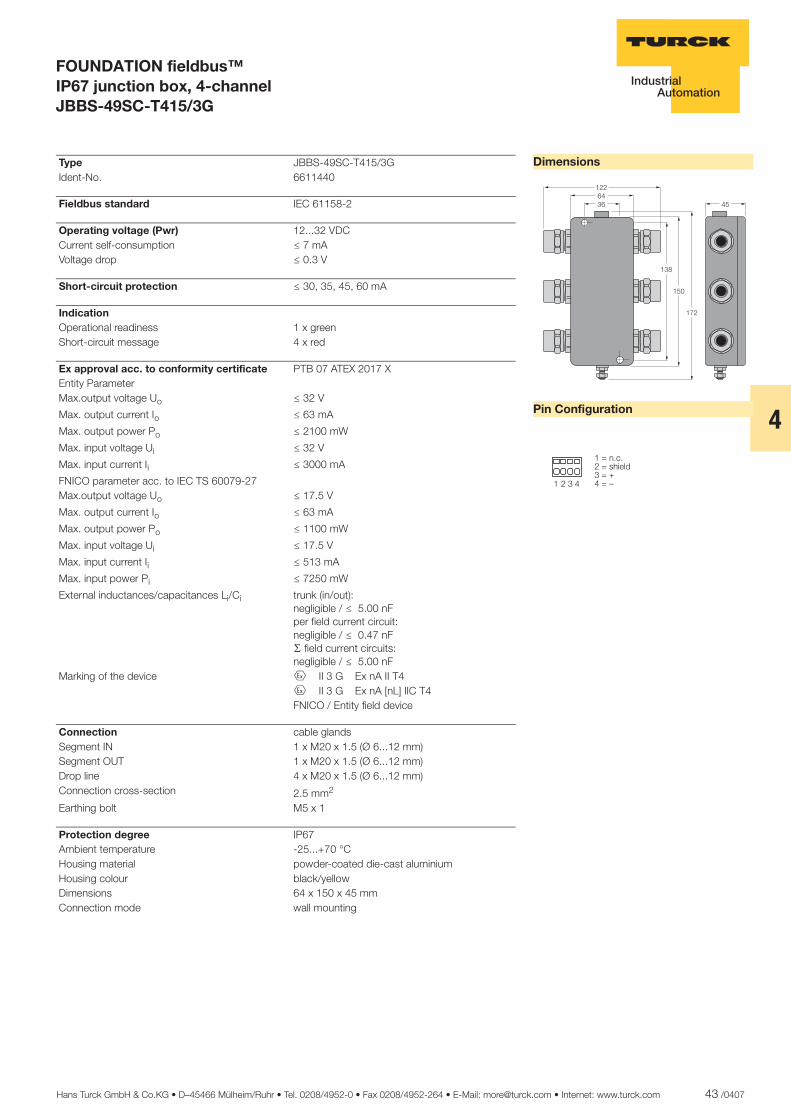
Hans Turck GmbH & Co.KG • D–45466 Mülheim/Ruhr • Tel. 0208/4952-0 • Fax 0208/4952-264 • E-Mail: [email protected] • Internet: www.turck.com 43 /0407
4
ñ Edition:
Hans Turck GmbH & Co.KG ñ D-45472 Mülheim an der Ruhr ñ Witzlebenstraße 7 ñ Tel. 0208 4952-0 ñ Fax 0208 4952-264 ñ [email protected] ñ www.turck.com
FOUNDATION fieldbus™ IP67 junction box, 4-channel JBBS-49SC-T415/3G
Dimensions
Pin Configuration
�������
���
��
��
��
� � � �
����������� �������������
Type JBBS-49SC-T415/3G Ident-No. 6611440
Fieldbus standard IEC 61158-2
Operating voltage (Pwr) 12...32 VDC Current self-consumption ð 7 mA Voltage drop ð 0.3 V
Short-circuit protection ð 30, 35, 45, 60 mA
Indication Operational readiness 1 x green Short-circuit message 4 x red
Ex approval acc. to conformity certificate PTB 07 ATEX 2017 X Entity Parameter Max.output voltage Uo ð 32 V
Max. output current Io ð 63 mA
Max. output power Po ð 2100 mW
Max. input voltage Ui ð 32 V
Max. input current Ii ð 3000 mA
FNICO parameter acc. to IEC TS 60079-27 Max.output voltage Uo ð 17.5 V
Max. output current Io ð 63 mA
Max. output power Po ð 1100 mW
Max. input voltage Ui ð 17.5 V
Max. input current Ii ð 513 mA
Max. input power Pi ð 7250 mW
External inductances/capacitances Li/Ci trunk (in/out):negligible / ð 5.00 nFper field current circuit:negligible / ð 0.47 nFæ field current circuits:negligible / ð 5.00 nF
Marking of the device É II 3 G Ex nA II T4 É II 3 G Ex nA [nL] IIC T4 FNICO / Entity field device
Connection cable glands Segment IN 1 x M20 x 1.5 (Ø 6...12 mm) Segment OUT 1 x M20 x 1.5 (Ø 6...12 mm) Drop line 4 x M20 x 1.5 (Ø 6...12 mm) Connection cross-section 2.5 mm2
Earthing bolt M5 x 1
Protection degree IP67 Ambient temperature -25...+70 °C Housing material powder-coated die-cast aluminium Housing colour black/yellow Dimensions 64 x 150 x 45 mm Connection mode wall mounting

44 /0407 Hans Turck GmbH & Co.KG • D–45466 Mülheim/Ruhr • Tel. 0208/4952-0 • Fax 0208/4952-264 • E-Mail: [email protected] • Internet: www.turck.com
ñ Edition:
Hans Turck GmbH & Co.KG ñ D-45472 Mülheim an der Ruhr ñ Witzlebenstraße 7 ñ Tel. 0208 4952-0 ñ Fax 0208 4952-264 ñ [email protected] ñ www.turck.com
FOUNDATION fieldbus™ IP67 junction box, 6-channel JBBS-49SC-T615/3G
� Entity and FNICO compliance acc. to IEC TS 60079-27
� Mounting in zone 2 possible
� Junction box for wall mounting with PVC cable glands M20 x 1.5
� Powder-coated die-cast aluminium housing
� Pressure compensation element for protection against condensation water
� Connection of the housing potential via an M5 x 1 bolt
� With drop line short-circuit protec-tion
� Integrated terminating resistor (switch-in)
� Cable shielding: capacitive or direct connection to housing potential se-lectable via switch
� Isolated support terminal for option-al protective conductor incorpora-ted in cable
The 6-channel Ex junction box, type JBBS-49SC-T615/3G is designed for the FOUN-DATION fieldbus™.
The junction box features an adjustable short-circuit limit. The max. current limita-tion is selected for all channels via a rotary switch. The following values can be se-lected: 30, 35, 45 and 60 mA.
The housing is made of robust die-cast alu-minium and features protection degree IP67.
The junction box is equipped with a select-able bus terminating resistor.
The according switch is integrated in the housing on the board.
To avoid condensation build-up in the hous-ing, the devices are equipped with a con-densate drain.
The shield is capacitively coupled to the housing potential. A switch for direct cou-pling of the shield and housing is imple-mented.
Attention: Sufficient equipotential bonding of the installation must be ensured. The de-vice is connected via the M5 x 1 bolt of the housing to the system’s potentializer.
����
����
���
����
�� ������
������
��
������
��
����
������
��
����
������
��
����
������
��
����
������
��
����
������
��
����
������
��
������� ��������
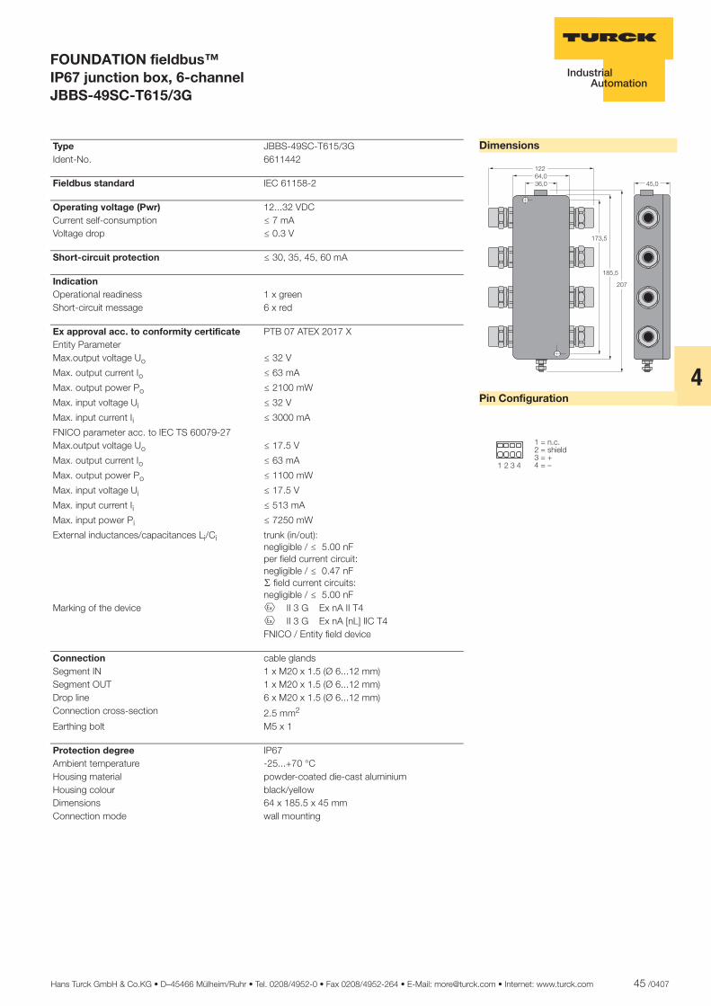
Hans Turck GmbH & Co.KG • D–45466 Mülheim/Ruhr • Tel. 0208/4952-0 • Fax 0208/4952-264 • E-Mail: [email protected] • Internet: www.turck.com 45 /0407
4
ñ Edition:
Hans Turck GmbH & Co.KG ñ D-45472 Mülheim an der Ruhr ñ Witzlebenstraße 7 ñ Tel. 0208 4952-0 ñ Fax 0208 4952-264 ñ [email protected] ñ www.turck.com
FOUNDATION fieldbus™ IP67 junction box, 6-channel JBBS-49SC-T615/3G
Dimensions
Pin Configuration
�����������
��
����
���
���
� � � �
����������� �������������
Type JBBS-49SC-T615/3G Ident-No. 6611442
Fieldbus standard IEC 61158-2
Operating voltage (Pwr) 12...32 VDC Current self-consumption ð 7 mA Voltage drop ð 0.3 V
Short-circuit protection ð 30, 35, 45, 60 mA
Indication Operational readiness 1 x green Short-circuit message 6 x red
Ex approval acc. to conformity certificate PTB 07 ATEX 2017 X Entity Parameter Max.output voltage Uo ð 32 V
Max. output current Io ð 63 mA
Max. output power Po ð 2100 mW
Max. input voltage Ui ð 32 V
Max. input current Ii ð 3000 mA
FNICO parameter acc. to IEC TS 60079-27 Max.output voltage Uo ð 17.5 V
Max. output current Io ð 63 mA
Max. output power Po ð 1100 mW
Max. input voltage Ui ð 17.5 V
Max. input current Ii ð 513 mA
Max. input power Pi ð 7250 mW
External inductances/capacitances Li/Ci trunk (in/out):negligible / ð 5.00 nFper field current circuit:negligible / ð 0.47 nFæ field current circuits:negligible / ð 5.00 nF
Marking of the device É II 3 G Ex nA II T4 É II 3 G Ex nA [nL] IIC T4 FNICO / Entity field device
Connection cable glands Segment IN 1 x M20 x 1.5 (Ø 6...12 mm) Segment OUT 1 x M20 x 1.5 (Ø 6...12 mm) Drop line 6 x M20 x 1.5 (Ø 6...12 mm) Connection cross-section 2.5 mm2
Earthing bolt M5 x 1
Protection degree IP67 Ambient temperature -25...+70 °C Housing material powder-coated die-cast aluminium Housing colour black/yellow Dimensions 64 x 185.5 x 45 mm Connection mode wall mounting
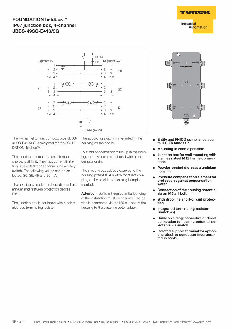
46 /0407 Hans Turck GmbH & Co.KG • D–45466 Mülheim/Ruhr • Tel. 0208/4952-0 • Fax 0208/4952-264 • E-Mail: [email protected] • Internet: www.turck.com
ñ Edition:
Hans Turck GmbH & Co.KG ñ D-45472 Mülheim an der Ruhr ñ Witzlebenstraße 7 ñ Tel. 0208 4952-0 ñ Fax 0208 4952-264 ñ [email protected] ñ www.turck.com
FOUNDATION fieldbus™ IP67 junction box, 4-channel JBBS-49SC-E413/3G
� Entity and FNICO compliance acc. to IEC TS 60079-27
� Mounting in zone 2 possible
� Junction box for wall mounting with stainless steel M12 flange connec-tions
� Powder-coated die-cast aluminium housing
� Pressure compensation element for protection against condensation water
� Connection of the housing potential via an M5 x 1 bolt
� With drop line short-circuit protec-tion
� Integrated terminating resistor (switch-in)
� Cable shielding: capacitive or direct connection to housing potential se-lectable via switch
� Isolated support terminal for option-al protective conductor incorpora-ted in cable
�� �
�� �
�� �
�� �
�����������
�����������
��������
The 4-channel Ex junction box, type JBBS-49SC-E413/3G is designed for the FOUN-DATION fieldbus™.
The junction box features an adjustable short-circuit limit. The max. current limita-tion is selected for all channels via a rotary switch. The following values can be se-lected: 30, 35, 45 and 60 mA.
The housing is made of robust die-cast alu-minium and features protection degree IP67.
The junction box is equipped with a select-able bus terminating resistor.
The according switch is integrated in the housing on the board.
To avoid condensation build-up in the hous-ing, the devices are equipped with a con-densate drain.
The shield is capacitively coupled to the housing potential. A switch for direct cou-pling of the shield and housing is imple-mented.
Attention: Sufficient equipotential bonding of the installation must be ensured. The de-vice is connected via the M5 x 1 bolt of the housing to the system’s potentializer.
����
����
���
����
�� ������
�������
�� ��
����
��
����
��
����
��
����
��
�������
�������
�������
�������
�������
� �� ���� � �� ����
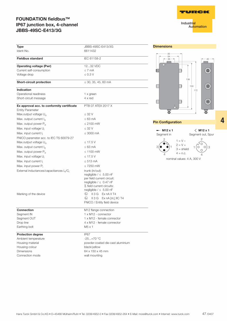
Hans Turck GmbH & Co.KG • D–45466 Mülheim/Ruhr • Tel. 0208/4952-0 • Fax 0208/4952-264 • E-Mail: [email protected] • Internet: www.turck.com 47 /0407
4
ñ Edition:
Hans Turck GmbH & Co.KG ñ D-45472 Mülheim an der Ruhr ñ Witzlebenstraße 7 ñ Tel. 0208 4952-0 ñ Fax 0208 4952-264 ñ [email protected] ñ www.turck.com
FOUNDATION fieldbus™ IP67 junction box, 4-channel JBBS-49SC-E413/3G
Dimensions
Pin Configuration
������
���
���
�
��
������� �������
�
� �
�
�
�
�
�
������ ���������������
� ���������������������
�������������������� ������� !
Type JBBS-49SC-E413/3G Ident-No. 6611432
Fieldbus standard IEC 61158-2
Operating voltage (Pwr) 12...32 VDC Current self-consumption ð 7 mA Voltage drop ð 0.3 V
Short-circuit protection ð 30, 35, 45, 60 mA
Indication Operational readiness 1 x green Short-circuit message 4 x red
Ex approval acc. to conformity certificate PTB 07 ATEX 2017 X Entity Parameter Max.output voltage Uo ð 32 V
Max. output current Io ð 63 mA
Max. output power Po ð 2100 mW
Max. input voltage Ui ð 32 V
Max. input current Ii ð 3000 mA
FNICO parameter acc. to IEC TS 60079-27 Max.output voltage Uo ð 17.5 V
Max. output current Io ð 63 mA
Max. output power Po ð 1100 mW
Max. input voltage Ui ð 17.5 V
Max. input current Ii ð 513 mA
Max. input power Pi ð 7250 mW
External inductances/capacitances Li/Ci trunk (in/out):negligible / ð 5.00 nFper field current circuit:negligible / ð 0.47 nFæ field current circuits:negligible / ð 5.00 nF
Marking of the device É II 3 G Ex nA II T4 É II 3 G Ex nA [nL] IIC T4 FNICO / Entity field device
Connection M12 flange connection Segment IN 1 x M12 - connector Segment OUT 1 x M12 - female connector Drop line 4 x M12 - female connector Earthing bolt M5 x 1
Protection degree IP67 Ambient temperature -25...+70 °C Housing material powder-coated die-cast aluminium Housing colour black/yellow Dimensions 64 x 150 x 45 mm Connection mode wall mounting
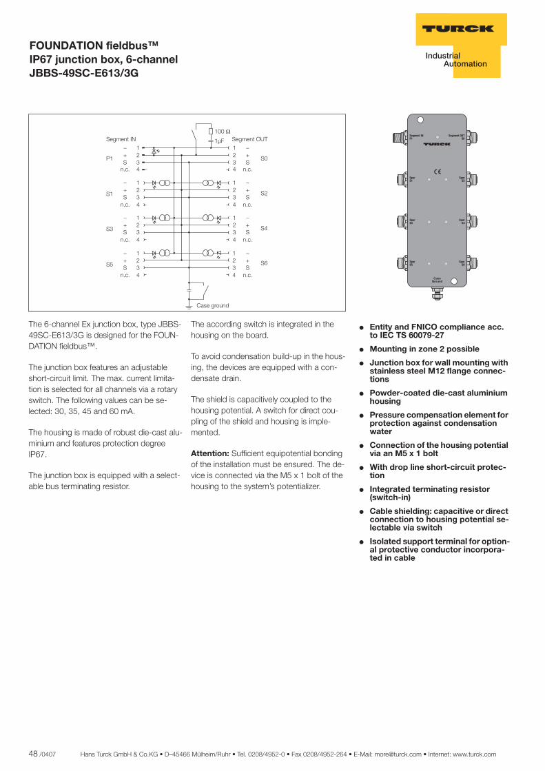
48 /0407 Hans Turck GmbH & Co.KG • D–45466 Mülheim/Ruhr • Tel. 0208/4952-0 • Fax 0208/4952-264 • E-Mail: [email protected] • Internet: www.turck.com
ñ Edition:
Hans Turck GmbH & Co.KG ñ D-45472 Mülheim an der Ruhr ñ Witzlebenstraße 7 ñ Tel. 0208 4952-0 ñ Fax 0208 4952-264 ñ [email protected] ñ www.turck.com
FOUNDATION fieldbus™ IP67 junction box, 6-channel JBBS-49SC-E613/3G
� Entity and FNICO compliance acc. to IEC TS 60079-27
� Mounting in zone 2 possible
� Junction box for wall mounting with stainless steel M12 flange connec-tions
� Powder-coated die-cast aluminium housing
� Pressure compensation element for protection against condensation water
� Connection of the housing potential via an M5 x 1 bolt
� With drop line short-circuit protec-tion
� Integrated terminating resistor (switch-in)
� Cable shielding: capacitive or direct connection to housing potential se-lectable via switch
� Isolated support terminal for option-al protective conductor incorpora-ted in cable
������
������
������
�����
��� ������
��� �������
��������
������
������
The 6-channel Ex junction box, type JBBS-49SC-E613/3G is designed for the FOUN-DATION fieldbus™.
The junction box features an adjustable short-circuit limit. The max. current limita-tion is selected for all channels via a rotary switch. The following values can be se-lected: 30, 35, 45 and 60 mA.
The housing is made of robust die-cast alu-minium and features protection degree IP67.
The junction box is equipped with a select-able bus terminating resistor.
The according switch is integrated in the housing on the board.
To avoid condensation build-up in the hous-ing, the devices are equipped with a con-densate drain.
The shield is capacitively coupled to the housing potential. A switch for direct cou-pling of the shield and housing is imple-mented.
Attention: Sufficient equipotential bonding of the installation must be ensured. The de-vice is connected via the M5 x 1 bolt of the housing to the system’s potentializer.
����
����
���
����
�� ������
�������
�� ��
����
��
����
��
����
��
����
��
�������
�������
����
��
����
��
�������
�������
�������
�������
�������
� �� ���� � �� �� !"
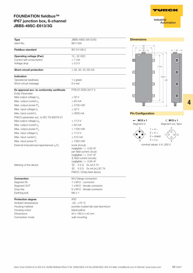
Hans Turck GmbH & Co.KG • D–45466 Mülheim/Ruhr • Tel. 0208/4952-0 • Fax 0208/4952-264 • E-Mail: [email protected] • Internet: www.turck.com 49 /0407
4
ñ Edition:
Hans Turck GmbH & Co.KG ñ D-45472 Mülheim an der Ruhr ñ Witzlebenstraße 7 ñ Tel. 0208 4952-0 ñ Fax 0208 4952-264 ñ [email protected] ñ www.turck.com
FOUNDATION fieldbus™ IP67 junction box, 6-channel JBBS-49SC-E613/3G
Dimensions
Pin Configuration
������
�����
����
��
�
������� �������
�
� �
�
�
�
�
�
������ ���������������
� ���������������������
�������������������� ������� !
Type JBBS-49SC-E613/3G Ident-No. 6611434
Fieldbus standard IEC 61158-2
Operating voltage (Pwr) 12...32 VDC Current self-consumption ð 7 mA Voltage drop ð 0.3 V
Short-circuit protection ð 30, 35, 45, 60 mA
Indication Operational readiness 1 x green Short-circuit message 6 x red
Ex approval acc. to conformity certificate PTB 07 ATEX 2017 X Entity Parameter Max.output voltage Uo ð 32 V
Max. output current Io ð 63 mA
Max. output power Po ð 2100 mW
Max. input voltage Ui ð 32 V
Max. input current Ii ð 3000 mA
FNICO parameter acc. to IEC TS 60079-27 Max.output voltage Uo ð 17.5 V
Max. output current Io ð 63 mA
Max. output power Po ð 1100 mW
Max. input voltage Ui ð 17.5 V
Max. input current Ii ð 513 mA
Max. input power Pi ð 7250 mW
External inductances/capacitances Li/Ci trunk (in/out):negligible / ð 5.00 nFper field current circuit:negligible / ð 0.47 nFæ field current circuits:negligible / ð 5.00 nF
Marking of the device É II 3 G Ex nA II T4 É II 3 G Ex nA [nL] IIC T4 FNICO / Entity field device
Connection M12 flange connection Segment IN 1 x M12 - connector Segment OUT 1 x M12 - female connector Drop line 6 x M12 - female connector Earthing bolt M5 x 1
Protection degree IP67 Ambient temperature -25...+70 °C Housing material powder-coated die-cast aluminium Housing colour black/yellow Dimensions 64 x 185.5 x 45 mm Connection mode wall mounting
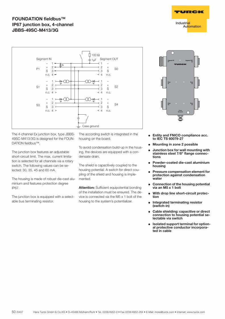
50 /0407 Hans Turck GmbH & Co.KG • D–45466 Mülheim/Ruhr • Tel. 0208/4952-0 • Fax 0208/4952-264 • E-Mail: [email protected] • Internet: www.turck.com
ñ Edition:
Hans Turck GmbH & Co.KG ñ D-45472 Mülheim an der Ruhr ñ Witzlebenstraße 7 ñ Tel. 0208 4952-0 ñ Fax 0208 4952-264 ñ [email protected] ñ www.turck.com
FOUNDATION fieldbus™ IP67 junction box, 4-channel JBBS-49SC-M413/3G
� Entity and FNICO compliance acc. to IEC TS 60079-27
� Mounting in zone 2 possible
� Junction box for wall mounting with stainless steel 7/8" flange connec-tions
� Powder-coated die-cast aluminium housing
� Pressure compensation element for protection against condensation water
� Connection of the housing potential via an M5 x 1 bolt
� With drop line short-circuit protec-tion
� Integrated terminating resistor (switch-in)
� Cable shielding: capacitive or direct connection to housing potential se-lectable via switch
� Isolated support terminal for option-al protective conductor incorpora-ted in cable
������
������
�����
�����
��� ��������
��� ���������
��������
The 4-channel Ex junction box, type JBBS-49SC-M413/3G is designed for the FOUN-DATION fieldbus™.
The junction box features an adjustable short-circuit limit. The max. current limita-tion is selected for all channels via a rotary switch. The following values can be se-lected: 30, 35, 45 and 60 mA.
The housing is made of robust die-cast alu-minium and features protection degree IP67.
The junction box is equipped with a select-able bus terminating resistor.
The according switch is integrated in the housing on the board.
To avoid condensation build-up in the hous-ing, the devices are equipped with a con-densate drain.
The shield is capacitively coupled to the housing potential. A switch for direct cou-pling of the shield and housing is imple-mented.
Attention: Sufficient equipotential bonding of the installation must be ensured. The de-vice is connected via the M5 x 1 bolt of the housing to the system’s potentializer.
����
����
���
����
�� ������
�������
�� ��
����
��
����
��
����
��
����
��
�������
�������
�������
�������
�������
� �� ���� � �� ����
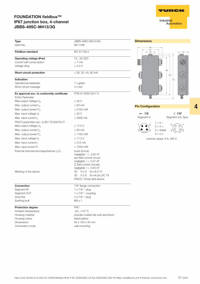
Hans Turck GmbH & Co.KG • D–45466 Mülheim/Ruhr • Tel. 0208/4952-0 • Fax 0208/4952-264 • E-Mail: [email protected] • Internet: www.turck.com 51 /0407
4
ñ Edition:
Hans Turck GmbH & Co.KG ñ D-45472 Mülheim an der Ruhr ñ Witzlebenstraße 7 ñ Tel. 0208 4952-0 ñ Fax 0208 4952-264 ñ [email protected] ñ www.turck.com
FOUNDATION fieldbus™ IP67 junction box, 4-channel JBBS-49SC-M413/3G
Dimensions
Pin Configuration
��
������
���
��
��
��� �������������
�
�
�
�
�����������������
�������������������������
��������������������� ����!"!
Type JBBS-49SC-M413/3G Ident-No. 6611436
Fieldbus standard IEC 61158-2
Operating voltage (Pwr) 12...32 VDC Current self-consumption ð 7 mA Voltage drop ð 0.3 V
Short-circuit protection ð 30, 35, 45, 60 mA
Indication Operational readiness 1 x green Short-circuit message 4 x red
Ex approval acc. to conformity certificate PTB 07 ATEX 2017 X Entity Parameter Max.output voltage Uo ð 32 V
Max. output current Io ð 63 mA
Max. output power Po ð 2100 mW
Max. input voltage Ui ð 32 V
Max. input current Ii ð 3000 mA
FNICO parameter acc. to IEC TS 60079-27 Max.output voltage Uo ð 17.5 V
Max. output current Io ð 63 mA
Max. output power Po ð 1100 mW
Max. input voltage Ui ð 17.5 V
Max. input current Ii ð 513 mA
Max. input power Pi ð 7250 mW
External inductances/capacitances Li/Ci trunk (in/out):negligible / ð 5.00 nFper field current circuit:negligible / ð 0.47 nFæ field current circuits:negligible / ð 5.00 nF
Marking of the device É II 3 G Ex nA II T4 É II 3 G Ex nA [nL] IIC T4 FNICO / Entity field device
Connection 7/8" flange connection Segment IN 1 x 7/8 "- plug Segment OUT 1 x 7/8 "- coupling Drop line 4 x 7/8 "- plug Earthing bolt M5 x 1
Protection degree IP67 Ambient temperature -25...+70 °C Housing material powder-coated die-cast aluminium Housing colour black/yellow Dimensions 64 x 150 x 45 mm Connection mode wall mounting

52 /0407 Hans Turck GmbH & Co.KG • D–45466 Mülheim/Ruhr • Tel. 0208/4952-0 • Fax 0208/4952-264 • E-Mail: [email protected] • Internet: www.turck.com
ñ Edition:
Hans Turck GmbH & Co.KG ñ D-45472 Mülheim an der Ruhr ñ Witzlebenstraße 7 ñ Tel. 0208 4952-0 ñ Fax 0208 4952-264 ñ [email protected] ñ www.turck.com
FOUNDATION fieldbus™ IP67 junction box, 6-channel JBBS-49SC-M613/3G
� Entity and FNICO compliance acc. to IEC TS 60079-27
� Mounting in zone 2 possible
� Junction box for wall mounting with stainless steel 7/8" flange connec-tions
� Powder-coated die-cast aluminium housing
� Pressure compensation element for protection against condensation water
� Connection of the housing potential via an M5 x 1 bolt
� With drop line short-circuit protec-tion
� Integrated terminating resistor (switch-in)
� Cable shielding: capacitive or direct connection to housing potential se-lectable via switch
� Isolated support terminal for option-al protective conductor incorpora-ted in cable
������
������
�����
�����
��� ��������
��� ���������
��������
������
������
The 6-channel Ex junction box, type JBBS-49SC-M613/3G is designed for the FOUN-DATION fieldbus™.
The junction box features an adjustable short-circuit limit. The max. current limita-tion is selected for all channels via a rotary switch. The following values can be se-lected: 30, 35, 45 and 60 mA.
The housing is made of robust die-cast alu-minium and features protection degree IP67.
The junction box is equipped with a select-able bus terminating resistor.
The according switch is integrated in the housing on the board.
To avoid condensation build-up in the hous-ing, the devices are equipped with a con-densate drain.
The shield is capacitively coupled to the housing potential. A switch for direct cou-pling of the shield and housing is imple-mented.
Attention: Sufficient equipotential bonding of the installation must be ensured. The de-vice is connected via the M5 x 1 bolt of the housing to the system’s potentializer.
����
����
���
����
�� ������
�������
�� ��
����
��
����
��
����
��
����
��
�������
�������
����
��
����
��
�������
�������
�������
�������
�������
� �� ���� � �� �� !"
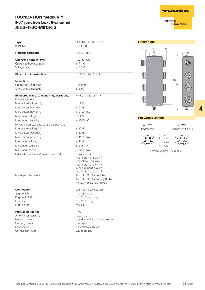
Hans Turck GmbH & Co.KG • D–45466 Mülheim/Ruhr • Tel. 0208/4952-0 • Fax 0208/4952-264 • E-Mail: [email protected] • Internet: www.turck.com 53 /0407
4
ñ Edition:
Hans Turck GmbH & Co.KG ñ D-45472 Mülheim an der Ruhr ñ Witzlebenstraße 7 ñ Tel. 0208 4952-0 ñ Fax 0208 4952-264 ñ [email protected] ñ www.turck.com
FOUNDATION fieldbus™ IP67 junction box, 6-channel JBBS-49SC-M613/3G
Dimensions
Pin Configuration
������ ��
����
���
��
��� �������������
�
�
�
�
�����������������
�������������������������
��������������������� ����!"!
Type JBBS-49SC-M613/3G Ident-No. 6611438
Fieldbus standard IEC 61158-2
Operating voltage (Pwr) 12...32 VDC Current self-consumption ð 7 mA Voltage drop ð 0.3 V
Short-circuit protection ð 30, 35, 45, 60 mA
Indication Operational readiness 1 x green Short-circuit message 6 x red
Ex approval acc. to conformity certificate PTB 07 ATEX 2017 X Entity Parameter Max.output voltage Uo ð 32 V
Max. output current Io ð 63 mA
Max. output power Po ð 2100 mW
Max. input voltage Ui ð 32 V
Max. input current Ii ð 3000 mA
FNICO parameter acc. to IEC TS 60079-27 Max.output voltage Uo ð 17.5 V
Max. output current Io ð 63 mA
Max. output power Po ð 1100 mW
Max. input voltage Ui ð 17.5 V
Max. input current Ii ð 513 mA
Max. input power Pi ð 7250 mW
External inductances/capacitances Li/Ci trunk (in/out):negligible / ð 5.00 nFper field current circuit:negligible / ð 0.47 nFæ field current circuits:negligible / ð 5.00 nF
Marking of the device É II 3 G Ex nA II T4 É II 3 G Ex nA [nL] IIC T4 FNICO / Entity field device
Connection 7/8" flange connection Segment IN 1 x 7/8 "- plug Segment OUT 1 x 7/8 "- coupling Drop line 6 x 7/8 "- plug Earthing bolt M5 x 1
Protection degree IP67 Ambient temperature -25...+70 °C Housing material powder-coated die-cast aluminium Housing colour black/yellow Dimensions 64 x 185.5 x 45 mm Connection mode wall mounting

54 /0407 Hans Turck GmbH & Co.KG • D–45466 Mülheim/Ruhr • Tel. 0208/4952-0 • Fax 0208/4952-264 • E-Mail: [email protected] • Internet: www.turck.com
ñ Edition:
Hans Turck GmbH & Co.KG ñ D-45472 Mülheim an der Ruhr ñ Witzlebenstraße 7 ñ Tel. 0208 4952-0 ñ Fax 0208 4952-264 ñ [email protected] ñ www.turck.com
FOUNDATION fieldbus™ IP67 junction box, 4-channel JBBS-49SC-T415B/EX
� Entity and FISCO compliance acc. to IEC TS 60079-27
� Junction box for wall mounting with PVC cable glands M20 x 1.5
� Powder-coated die-cast aluminium housing
� Pressure compensation element for protection against condensation water
� Connection of the housing potential via an M5 x 1 bolt
� With drop line short-circuit protec-tion
� Integrated terminating resistor (switch-in)
� Cable shielding: capacitive or direct connection to housing potential se-lectable via switch
� Isolated support terminal for option-al protective conductor incorpora-ted in cable
The 4-channel Ex junction box, type JBBS-49SC-T415B/EX is designed for the FOUN-DATION fieldbus™.
The junction box features an adjustable short-circuit limit. The max. current limita-tion is selected for all channels via a rotary switch. The following values can be se-lected: 30, 35, 45 and 60 mA.
The housing is made of robust die-cast alu-minium and features protection degree IP67.
The junction box is equipped with a select-able bus terminating resistor.
The according switch is integrated in the housing on the board.
To avoid condensation build-up in the hous-ing, the devices are equipped with a con-densate drain.
The shield is capacitively coupled to the housing potential. A switch for direct cou-pling of the shield and housing is imple-mented.
Attention: Sufficient equipotential bonding of the installation must be ensured. The de-vice is connected via the M5 x 1 bolt of the housing to the system’s potentializer.
����
����
���
����
�� ������
�������
��
�������
��
����
�������
��
����
�������
��
����
�������
��
����
�������
��
� �� ���� � �� ����
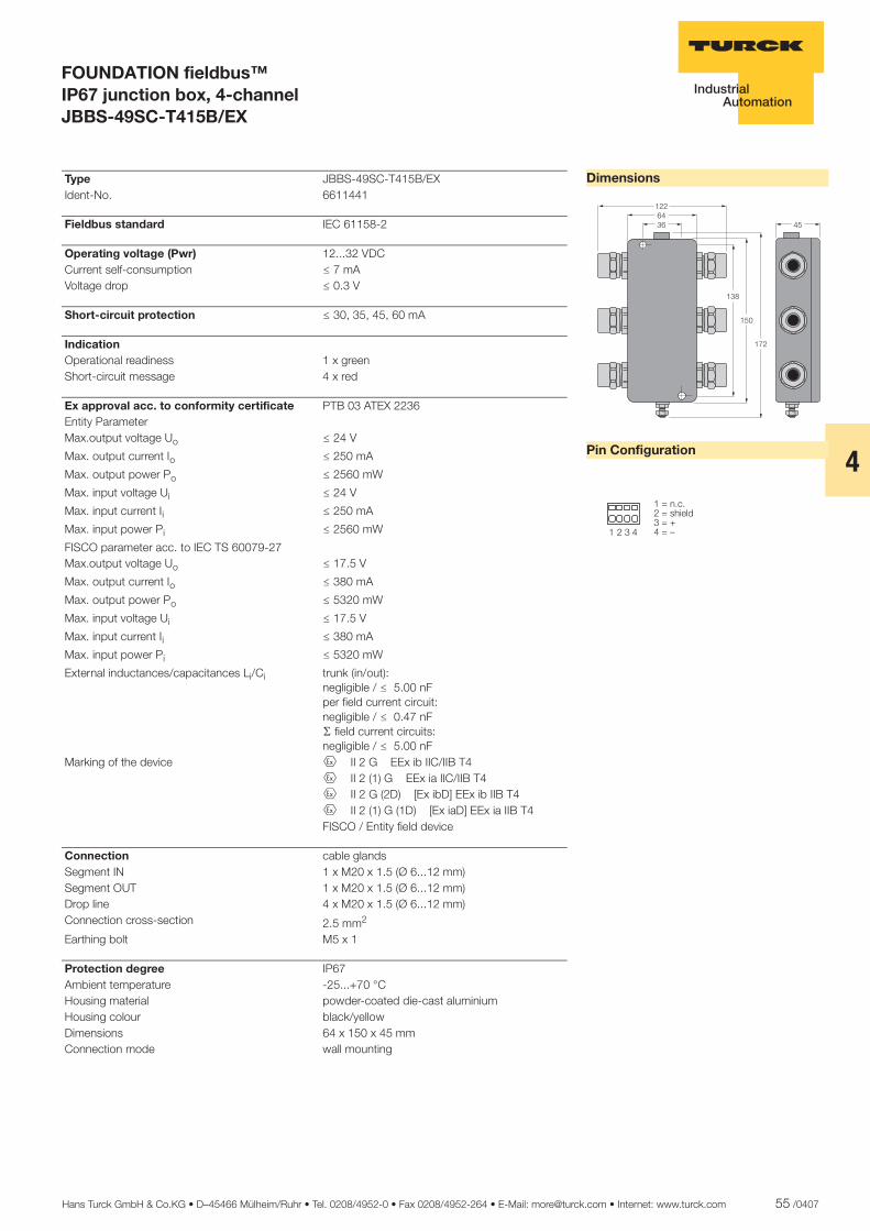
Hans Turck GmbH & Co.KG • D–45466 Mülheim/Ruhr • Tel. 0208/4952-0 • Fax 0208/4952-264 • E-Mail: [email protected] • Internet: www.turck.com 55 /0407
4
ñ Edition:
Hans Turck GmbH & Co.KG ñ D-45472 Mülheim an der Ruhr ñ Witzlebenstraße 7 ñ Tel. 0208 4952-0 ñ Fax 0208 4952-264 ñ [email protected] ñ www.turck.com
FOUNDATION fieldbus™ IP67 junction box, 4-channel JBBS-49SC-T415B/EX
Dimensions
Pin Configuration
�������
���
��
��
��
� � � �
����������� �������������
Type JBBS-49SC-T415B/EX Ident-No. 6611441
Fieldbus standard IEC 61158-2
Operating voltage (Pwr) 12...32 VDC Current self-consumption ð 7 mA Voltage drop ð 0.3 V
Short-circuit protection ð 30, 35, 45, 60 mA
Indication Operational readiness 1 x green Short-circuit message 4 x red
Ex approval acc. to conformity certificate PTB 03 ATEX 2236 Entity Parameter Max.output voltage Uo ð 24 V
Max. output current Io ð 250 mA
Max. output power Po ð 2560 mW
Max. input voltage Ui ð 24 V
Max. input current Ii ð 250 mA
Max. input power Pi ð 2560 mW
FISCO parameter acc. to IEC TS 60079-27 Max.output voltage Uo ð 17.5 V
Max. output current Io ð 380 mA
Max. output power Po ð 5320 mW
Max. input voltage Ui ð 17.5 V
Max. input current Ii ð 380 mA
Max. input power Pi ð 5320 mW
External inductances/capacitances Li/Ci trunk (in/out):negligible / ð 5.00 nFper field current circuit:negligible / ð 0.47 nFæ field current circuits:negligible / ð 5.00 nF
Marking of the device É II 2 G EEx ib IIC/IIB T4 É II 2 (1) G EEx ia IIC/IIB T4 É II 2 G (2D) [Ex ibD] EEx ib IIB T4 É II 2 (1) G (1D) [Ex iaD] EEx ia IIB T4 FISCO / Entity field device
Connection cable glands Segment IN 1 x M20 x 1.5 (Ø 6...12 mm) Segment OUT 1 x M20 x 1.5 (Ø 6...12 mm) Drop line 4 x M20 x 1.5 (Ø 6...12 mm) Connection cross-section 2.5 mm2
Earthing bolt M5 x 1
Protection degree IP67 Ambient temperature -25...+70 °C Housing material powder-coated die-cast aluminium Housing colour black/yellow Dimensions 64 x 150 x 45 mm Connection mode wall mounting

56 /0407 Hans Turck GmbH & Co.KG • D–45466 Mülheim/Ruhr • Tel. 0208/4952-0 • Fax 0208/4952-264 • E-Mail: [email protected] • Internet: www.turck.com
ñ Edition:
Hans Turck GmbH & Co.KG ñ D-45472 Mülheim an der Ruhr ñ Witzlebenstraße 7 ñ Tel. 0208 4952-0 ñ Fax 0208 4952-264 ñ [email protected] ñ www.turck.com
FOUNDATION fieldbus™ IP67 junction box, 6-channel JBBS-49SC-T615B/EX
� Entity and FISCO compliance acc. to IEC TS 60079-27
� Junction box for wall mounting with PVC cable glands M20 x 1.5
� Powder-coated die-cast aluminium housing
� Pressure compensation element for protection against condensation water
� Connection of the housing potential via an M5 x 1 bolt
� With drop line short-circuit protec-tion
� Integrated terminating resistor (switch-in)
� Cable shielding: capacitive or direct connection to housing potential se-lectable via switch
� Isolated support terminal for option-al protective conductor incorpora-ted in cable
The 6-channel Ex junction box, type JBBS-49SC-T615B/EX is designed for the FOUN-DATION fieldbus™.
The junction box features an adjustable short-circuit limit. The max. current limita-tion is selected for all channels via a rotary switch. The following values can be se-lected: 30, 35, 45 and 60 mA.
The housing is made of robust die-cast alu-minium and features protection degree IP67.
The junction box is equipped with a select-able bus terminating resistor.
The according switch is integrated in the housing on the board.
To avoid condensation build-up in the hous-ing, the devices are equipped with a con-densate drain.
The shield is capacitively coupled to the housing potential. A switch for direct cou-pling of the shield and housing is imple-mented.
Attention: Sufficient equipotential bonding of the installation must be ensured. The de-vice is connected via the M5 x 1 bolt of the housing to the system’s potentializer.
����
����
���
����
�� ������
������
��
������
��
����
������
��
����
������
��
����
������
��
����
������
��
����
������
��
����
������
��
������� ��������
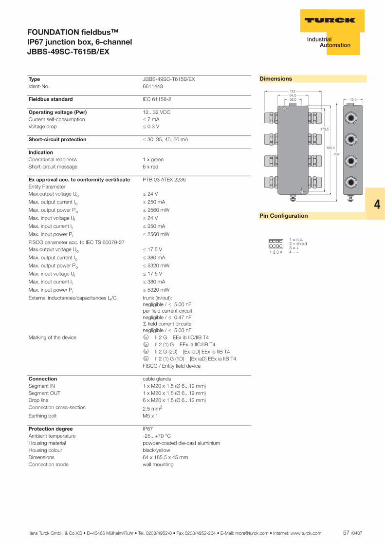
Hans Turck GmbH & Co.KG • D–45466 Mülheim/Ruhr • Tel. 0208/4952-0 • Fax 0208/4952-264 • E-Mail: [email protected] • Internet: www.turck.com 57 /0407
4
ñ Edition:
Hans Turck GmbH & Co.KG ñ D-45472 Mülheim an der Ruhr ñ Witzlebenstraße 7 ñ Tel. 0208 4952-0 ñ Fax 0208 4952-264 ñ [email protected] ñ www.turck.com
FOUNDATION fieldbus™ IP67 junction box, 6-channel JBBS-49SC-T615B/EX
Dimensions
Pin Configuration
�����������
��
����
���
���
� � � �
����������� �������������
Type JBBS-49SC-T615B/EX Ident-No. 6611443
Fieldbus standard IEC 61158-2
Operating voltage (Pwr) 12...32 VDC Current self-consumption ð 7 mA Voltage drop ð 0.3 V
Short-circuit protection ð 30, 35, 45, 60 mA
Indication Operational readiness 1 x green Short-circuit message 6 x red
Ex approval acc. to conformity certificate PTB 03 ATEX 2236 Entity Parameter Max.output voltage Uo ð 24 V
Max. output current Io ð 250 mA
Max. output power Po ð 2560 mW
Max. input voltage Ui ð 24 V
Max. input current Ii ð 250 mA
Max. input power Pi ð 2560 mW
FISCO parameter acc. to IEC TS 60079-27 Max.output voltage Uo ð 17.5 V
Max. output current Io ð 380 mA
Max. output power Po ð 5320 mW
Max. input voltage Ui ð 17.5 V
Max. input current Ii ð 380 mA
Max. input power Pi ð 5320 mW
External inductances/capacitances Li/Ci trunk (in/out):negligible / ð 5.00 nFper field current circuit:negligible / ð 0.47 nFæ field current circuits:negligible / ð 5.00 nF
Marking of the device É II 2 G EEx ib IIC/IIB T4 É II 2 (1) G EEx ia IIC/IIB T4 É II 2 G (2D) [Ex ibD] EEx ib IIB T4 É II 2 (1) G (1D) [Ex iaD] EEx ia IIB T4 FISCO / Entity field device
Connection cable glands Segment IN 1 x M20 x 1.5 (Ø 6...12 mm) Segment OUT 1 x M20 x 1.5 (Ø 6...12 mm) Drop line 6 x M20 x 1.5 (Ø 6...12 mm) Connection cross-section 2.5 mm2
Earthing bolt M5 x 1
Protection degree IP67 Ambient temperature -25...+70 °C Housing material powder-coated die-cast aluminium Housing colour black/yellow Dimensions 64 x 185.5 x 45 mm Connection mode wall mounting
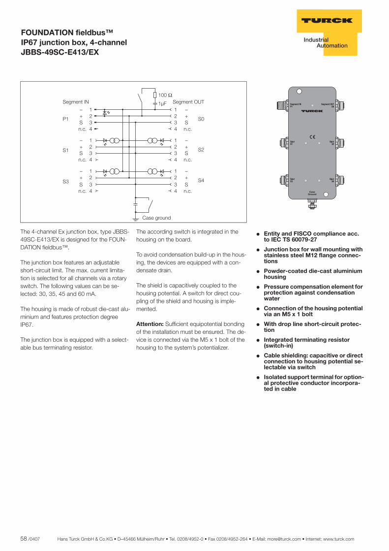
58 /0407 Hans Turck GmbH & Co.KG • D–45466 Mülheim/Ruhr • Tel. 0208/4952-0 • Fax 0208/4952-264 • E-Mail: [email protected] • Internet: www.turck.com
ñ Edition:
Hans Turck GmbH & Co.KG ñ D-45472 Mülheim an der Ruhr ñ Witzlebenstraße 7 ñ Tel. 0208 4952-0 ñ Fax 0208 4952-264 ñ [email protected] ñ www.turck.com
FOUNDATION fieldbus™ IP67 junction box, 4-channel JBBS-49SC-E413/EX
� Entity and FISCO compliance acc. to IEC TS 60079-27
� Junction box for wall mounting with stainless steel M12 flange connec-tions
� Powder-coated die-cast aluminium housing
� Pressure compensation element for protection against condensation water
� Connection of the housing potential via an M5 x 1 bolt
� With drop line short-circuit protec-tion
� Integrated terminating resistor (switch-in)
� Cable shielding: capacitive or direct connection to housing potential se-lectable via switch
� Isolated support terminal for option-al protective conductor incorpora-ted in cable
������
������
������
�����
��� ������
��� �������
��������
The 4-channel Ex junction box, type JBBS-49SC-E413/EX is designed for the FOUN-DATION fieldbus™.
The junction box features an adjustable short-circuit limit. The max. current limita-tion is selected for all channels via a rotary switch. The following values can be se-lected: 30, 35, 45 and 60 mA.
The housing is made of robust die-cast alu-minium and features protection degree IP67.
The junction box is equipped with a select-able bus terminating resistor.
The according switch is integrated in the housing on the board.
To avoid condensation build-up in the hous-ing, the devices are equipped with a con-densate drain.
The shield is capacitively coupled to the housing potential. A switch for direct cou-pling of the shield and housing is imple-mented.
Attention: Sufficient equipotential bonding of the installation must be ensured. The de-vice is connected via the M5 x 1 bolt of the housing to the system’s potentializer.
����
����
���
����
�� ������
�������
�� ��
����
��
����
��
����
��
����
��
�������
�������
�������
�������
�������
� �� ���� � �� ����
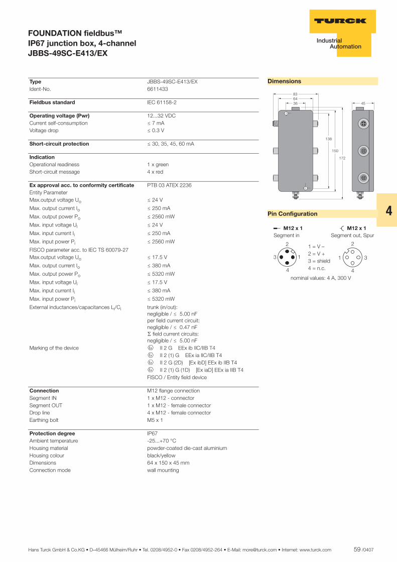
Hans Turck GmbH & Co.KG • D–45466 Mülheim/Ruhr • Tel. 0208/4952-0 • Fax 0208/4952-264 • E-Mail: [email protected] • Internet: www.turck.com 59 /0407
4
ñ Edition:
Hans Turck GmbH & Co.KG ñ D-45472 Mülheim an der Ruhr ñ Witzlebenstraße 7 ñ Tel. 0208 4952-0 ñ Fax 0208 4952-264 ñ [email protected] ñ www.turck.com
FOUNDATION fieldbus™ IP67 junction box, 4-channel JBBS-49SC-E413/EX
Dimensions
Pin Configuration
������
���
���
�
��
������� �������
�
� �
�
�
�
�
�
������ ���������������
� ���������������������
�������������������� ������� !
Type JBBS-49SC-E413/EX Ident-No. 6611433
Fieldbus standard IEC 61158-2
Operating voltage (Pwr) 12...32 VDC Current self-consumption ð 7 mA Voltage drop ð 0.3 V
Short-circuit protection ð 30, 35, 45, 60 mA
Indication Operational readiness 1 x green Short-circuit message 4 x red
Ex approval acc. to conformity certificate PTB 03 ATEX 2236 Entity Parameter Max.output voltage Uo ð 24 V
Max. output current Io ð 250 mA
Max. output power Po ð 2560 mW
Max. input voltage Ui ð 24 V
Max. input current Ii ð 250 mA
Max. input power Pi ð 2560 mW
FISCO parameter acc. to IEC TS 60079-27 Max.output voltage Uo ð 17.5 V
Max. output current Io ð 380 mA
Max. output power Po ð 5320 mW
Max. input voltage Ui ð 17.5 V
Max. input current Ii ð 380 mA
Max. input power Pi ð 5320 mW
External inductances/capacitances Li/Ci trunk (in/out):negligible / ð 5.00 nFper field current circuit:negligible / ð 0.47 nFæ field current circuits:negligible / ð 5.00 nF
Marking of the device É II 2 G EEx ib IIC/IIB T4 É II 2 (1) G EEx ia IIC/IIB T4 É II 2 G (2D) [Ex ibD] EEx ib IIB T4 É II 2 (1) G (1D) [Ex iaD] EEx ia IIB T4 FISCO / Entity field device
Connection M12 flange connection Segment IN 1 x M12 - connector Segment OUT 1 x M12 - female connector Drop line 4 x M12 - female connector Earthing bolt M5 x 1
Protection degree IP67 Ambient temperature -25...+70 °C Housing material powder-coated die-cast aluminium Housing colour black/yellow Dimensions 64 x 150 x 45 mm Connection mode wall mounting

60 /0407 Hans Turck GmbH & Co.KG • D–45466 Mülheim/Ruhr • Tel. 0208/4952-0 • Fax 0208/4952-264 • E-Mail: [email protected] • Internet: www.turck.com
ñ Edition:
Hans Turck GmbH & Co.KG ñ D-45472 Mülheim an der Ruhr ñ Witzlebenstraße 7 ñ Tel. 0208 4952-0 ñ Fax 0208 4952-264 ñ [email protected] ñ www.turck.com
FOUNDATION fieldbus™ IP67 junction box, 6-channel JBBS-49SC-E613/EX
� Entity and FISCO compliance acc. to IEC TS 60079-27
� Junction box for wall mounting with stainless steel M12 flange connec-tions
� Powder-coated die-cast aluminium housing
� Pressure compensation element for protection against condensation water
� Connection of the housing potential via an M5 x 1 bolt
� With drop line short-circuit protec-tion
� Integrated terminating resistor (switch-in)
� Cable shielding: capacitive or direct connection to housing potential se-lectable via switch
� Isolated support terminal for option-al protective conductor incorpora-ted in cable
������
������
������
�����
��� ������
��� �������
��������
������
������
The 6-channel Ex junction box, type JBBS-49SC-E613/EX is designed for the FOUN-DATION fieldbus™.
The junction box features an adjustable short-circuit limit. The max. current limita-tion is selected for all channels via a rotary switch. The following values can be se-lected: 30, 35, 45 and 60 mA.
The housing is made of robust die-cast alu-minium and features protection degree IP67.
The junction box is equipped with a select-able bus terminating resistor.
The according switch is integrated in the housing on the board.
To avoid condensation build-up in the hous-ing, the devices are equipped with a con-densate drain.
The shield is capacitively coupled to the housing potential. A switch for direct cou-pling of the shield and housing is imple-mented.
Attention: Sufficient equipotential bonding of the installation must be ensured. The de-vice is connected via the M5 x 1 bolt of the housing to the system’s potentializer.
����
����
���
����
�� ������
�������
�� ��
����
��
����
��
����
��
����
��
�������
�������
����
��
����
��
�������
�������
�������
�������
�������
� �� ���� � �� �� !"
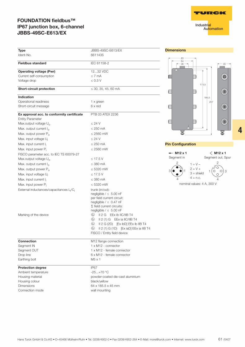
Hans Turck GmbH & Co.KG • D–45466 Mülheim/Ruhr • Tel. 0208/4952-0 • Fax 0208/4952-264 • E-Mail: [email protected] • Internet: www.turck.com 61 /0407
4
ñ Edition:
Hans Turck GmbH & Co.KG ñ D-45472 Mülheim an der Ruhr ñ Witzlebenstraße 7 ñ Tel. 0208 4952-0 ñ Fax 0208 4952-264 ñ [email protected] ñ www.turck.com
FOUNDATION fieldbus™ IP67 junction box, 6-channel JBBS-49SC-E613/EX
Dimensions
Pin Configuration
������
�����
����
��
�
������� �������
�
� �
�
�
�
�
�
������ ���������������
� ���������������������
�������������������� ������� !
Type JBBS-49SC-E613/EX Ident-No. 6611435
Fieldbus standard IEC 61158-2
Operating voltage (Pwr) 12...32 VDC Current self-consumption ð 7 mA Voltage drop ð 0.3 V
Short-circuit protection ð 30, 35, 45, 60 mA
Indication Operational readiness 1 x green Short-circuit message 6 x red
Ex approval acc. to conformity certificate PTB 03 ATEX 2236 Entity Parameter Max.output voltage Uo ð 24 V
Max. output current Io ð 250 mA
Max. output power Po ð 2560 mW
Max. input voltage Ui ð 24 V
Max. input current Ii ð 250 mA
Max. input power Pi ð 2560 mW
FISCO parameter acc. to IEC TS 60079-27 Max.output voltage Uo ð 17.5 V
Max. output current Io ð 380 mA
Max. output power Po ð 5320 mW
Max. input voltage Ui ð 17.5 V
Max. input current Ii ð 380 mA
Max. input power Pi ð 5320 mW
External inductances/capacitances Li/Ci trunk (in/out):negligible / ð 5.00 nFper field current circuit:negligible / ð 0.47 nFæ field current circuits:negligible / ð 5.00 nF
Marking of the device É II 2 G EEx ib IIC/IIB T4 É II 2 (1) G EEx ia IIC/IIB T4 É II 2 G (2D) [Ex ibD] EEx ib IIB T4 É II 2 (1) G (1D) [Ex iaD] EEx ia IIB T4 FISCO / Entity field device
Connection M12 flange connection Segment IN 1 x M12 - connector Segment OUT 1 x M12 - female connector Drop line 6 x M12 - female connector Earthing bolt M5 x 1
Protection degree IP67 Ambient temperature -25...+70 °C Housing material powder-coated die-cast aluminium Housing colour black/yellow Dimensions 64 x 185.5 x 45 mm Connection mode wall mounting

62 /0407 Hans Turck GmbH & Co.KG • D–45466 Mülheim/Ruhr • Tel. 0208/4952-0 • Fax 0208/4952-264 • E-Mail: [email protected] • Internet: www.turck.com
ñ Edition:
Hans Turck GmbH & Co.KG ñ D-45472 Mülheim an der Ruhr ñ Witzlebenstraße 7 ñ Tel. 0208 4952-0 ñ Fax 0208 4952-264 ñ [email protected] ñ www.turck.com
FOUNDATION fieldbus™ IP67 junction box, 4-channel JBBS-49SC-M413/EX
� Entity and FISCO compliance acc. to IEC TS 60079-27
� Junction box for wall mounting with stainless steel 7/8" flange connec-tions
� Powder-coated die-cast aluminium housing
� Pressure compensation element for protection against condensation water
� Connection of the housing potential via an M5 x 1 bolt
� With drop line short-circuit protec-tion
� Integrated terminating resistor (switch-in)
� Cable shielding: capacitive or direct connection to housing potential se-lectable via switch
� Isolated support terminal for option-al protective conductor incorpora-ted in cable
������
������
�����
�����
��� ��������
��� ���������
��������
The 4-channel Ex junction box, type JBBS-49SC-M413/EX is designed for the FOUN-DATION fieldbus™.
The junction box features an adjustable short-circuit limit. The max. current limita-tion is selected for all channels via a rotary switch. The following values can be se-lected: 30, 35, 45 and 60 mA.
The housing is made of robust die-cast alu-minium and features protection degree IP67.
The junction box is equipped with a select-able bus terminating resistor.
The according switch is integrated in the housing on the board.
To avoid condensation build-up in the hous-ing, the devices are equipped with a con-densate drain.
The shield is capacitively coupled to the housing potential. A switch for direct cou-pling of the shield and housing is imple-mented.
Attention: Sufficient equipotential bonding of the installation must be ensured. The de-vice is connected via the M5 x 1 bolt of the housing to the system’s potentializer.
����
����
���
����
�� ������
�������
�� ��
����
��
����
��
����
��
����
��
�������
�������
�������
�������
�������
� �� ���� � �� ����

Hans Turck GmbH & Co.KG • D–45466 Mülheim/Ruhr • Tel. 0208/4952-0 • Fax 0208/4952-264 • E-Mail: [email protected] • Internet: www.turck.com 63 /0407
4
ñ Edition:
Hans Turck GmbH & Co.KG ñ D-45472 Mülheim an der Ruhr ñ Witzlebenstraße 7 ñ Tel. 0208 4952-0 ñ Fax 0208 4952-264 ñ [email protected] ñ www.turck.com
FOUNDATION fieldbus™ IP67 junction box, 4-channel JBBS-49SC-M413/EX
Dimensions
Pin Configuration
��
������
���
��
��
��� �������������
�
�
�
�
�����������������
�������������������������
��������������������� ����!"!
Type JBBS-49SC-M413/EX Ident-No. 6611437
Fieldbus standard IEC 61158-2
Operating voltage (Pwr) 12...32 VDC Current self-consumption ð 7 mA Voltage drop ð 0.3 V
Short-circuit protection ð 30, 35, 45, 60 mA
Indication Operational readiness 1 x green Short-circuit message 4 x red
Ex approval acc. to conformity certificate PTB 03 ATEX 2236 Entity Parameter Max.output voltage Uo ð 24 V
Max. output current Io ð 250 mA
Max. output power Po ð 2560 mW
Max. input voltage Ui ð 24 V
Max. input current Ii ð 250 mA
Max. input power Pi ð 2560 mW
FISCO parameter acc. to IEC TS 60079-27 Max.output voltage Uo ð 17.5 V
Max. output current Io ð 380 mA
Max. output power Po ð 5320 mW
Max. input voltage Ui ð 17.5 V
Max. input current Ii ð 380 mA
Max. input power Pi ð 5320 mW
External inductances/capacitances Li/Ci trunk (in/out):negligible / ð 5.00 nFper field current circuit:negligible / ð 0.47 nFæ field current circuits:negligible / ð 5.00 nF
Marking of the device É II 2 G EEx ib IIC/IIB T4 É II 2 (1) G EEx ia IIC/IIB T4 É II 2 G (2D) [Ex ibD] EEx ib IIB T4 É II 2 (1) G (1D) [Ex iaD] EEx ia IIB T4 FISCO / Entity field device
Connection 7/8" flange connection Segment IN 1 x 7/8 "- plug Segment OUT 1 x 7/8 "- coupling Drop line 4 x 7/8 "- plug Earthing bolt M5 x 1
Protection degree IP67 Ambient temperature -25...+70 °C Housing material powder-coated die-cast aluminium Housing colour black/yellow Dimensions 64 x 150 x 45 mm Connection mode wall mounting

64 /0407 Hans Turck GmbH & Co.KG • D–45466 Mülheim/Ruhr • Tel. 0208/4952-0 • Fax 0208/4952-264 • E-Mail: [email protected] • Internet: www.turck.com
ñ Edition:
Hans Turck GmbH & Co.KG ñ D-45472 Mülheim an der Ruhr ñ Witzlebenstraße 7 ñ Tel. 0208 4952-0 ñ Fax 0208 4952-264 ñ [email protected] ñ www.turck.com
FOUNDATION fieldbus™ IP67 junction box, 6-channel JBBS-49SC-M613/EX
� Entity and FISCO compliance acc. to IEC TS 60079-27
� Junction box for wall mounting with stainless steel 7/8" flange connec-tions
� Powder-coated die-cast aluminium housing
� Pressure compensation element for protection against condensation water
� Connection of the housing potential via an M5 x 1 bolt
� With drop line short-circuit protec-tion
� Integrated terminating resistor (switch-in)
� Cable shielding: capacitive or direct connection to housing potential se-lectable via switch
� Isolated support terminal for option-al protective conductor incorpora-ted in cable
������
������
�����
�����
��� ��������
��� ���������
��������
������
������
The 6-channel Ex junction box, type JBBS-49SC-M613/EX is designed for the FOUN-DATION fieldbus™.
The junction box features an adjustable short-circuit limit. The max. current limita-tion is selected for all channels via a rotary switch. The following values can be se-lected: 30, 35, 45 and 60 mA.
The housing is made of robust die-cast alu-minium and features protection degree IP67.
The junction box is equipped with a select-able bus terminating resistor.
The according switch is integrated in the housing on the board.
To avoid condensation build-up in the hous-ing, the devices are equipped with a con-densate drain.
The shield is capacitively coupled to the housing potential. A switch for direct cou-pling of the shield and housing is imple-mented.
Attention: Sufficient equipotential bonding of the installation must be ensured. The de-vice is connected via the M5 x 1 bolt of the housing to the system’s potentializer.
����
����
���
����
�� ������
�������
�� ��
����
��
����
��
����
��
����
��
�������
�������
����
��
����
��
�������
�������
�������
�������
�������
� �� ���� � �� �� !"
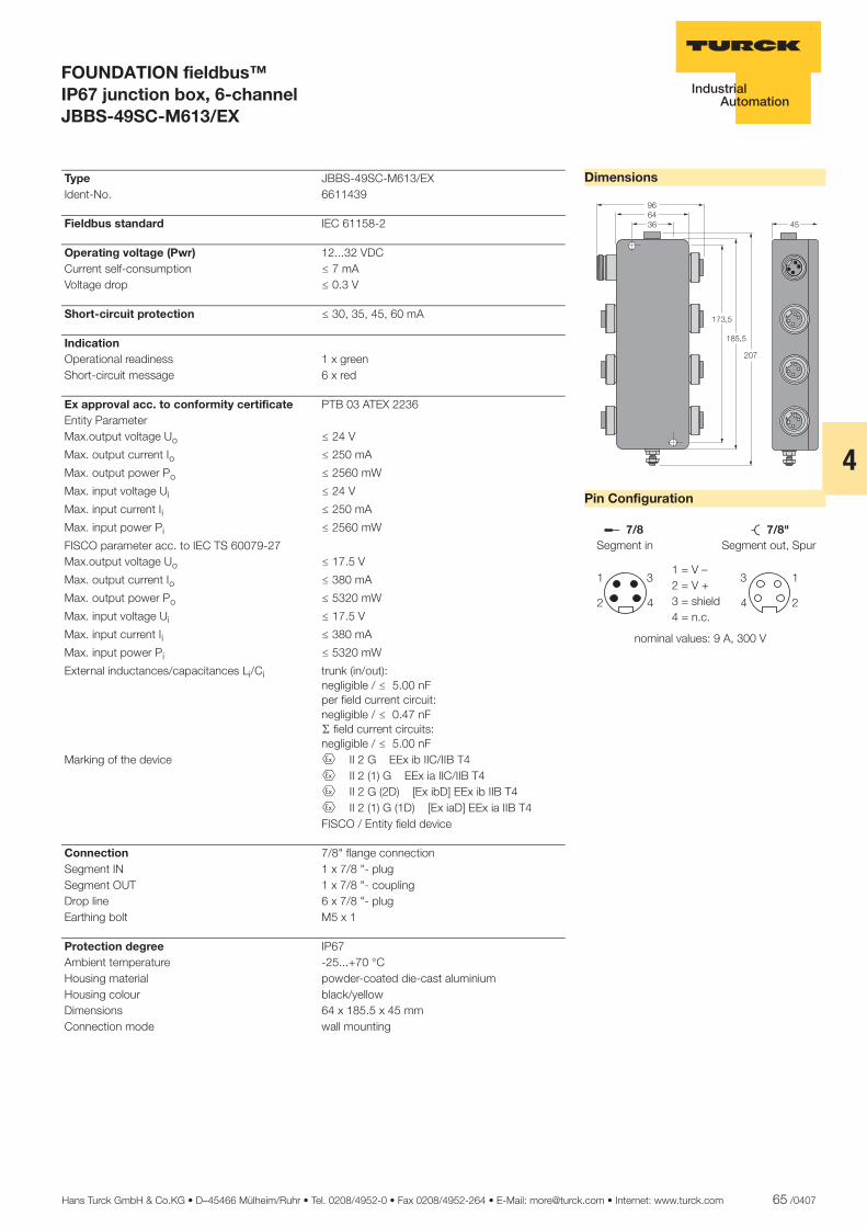
Hans Turck GmbH & Co.KG • D–45466 Mülheim/Ruhr • Tel. 0208/4952-0 • Fax 0208/4952-264 • E-Mail: [email protected] • Internet: www.turck.com 65 /0407
4
ñ Edition:
Hans Turck GmbH & Co.KG ñ D-45472 Mülheim an der Ruhr ñ Witzlebenstraße 7 ñ Tel. 0208 4952-0 ñ Fax 0208 4952-264 ñ [email protected] ñ www.turck.com
FOUNDATION fieldbus™ IP67 junction box, 6-channel JBBS-49SC-M613/EX
Dimensions
Pin Configuration
������ ��
����
���
��
��� �������������
�
�
�
�
�����������������
�������������������������
��������������������� ����!"!
Type JBBS-49SC-M613/EX Ident-No. 6611439
Fieldbus standard IEC 61158-2
Operating voltage (Pwr) 12...32 VDC Current self-consumption ð 7 mA Voltage drop ð 0.3 V
Short-circuit protection ð 30, 35, 45, 60 mA
Indication Operational readiness 1 x green Short-circuit message 6 x red
Ex approval acc. to conformity certificate PTB 03 ATEX 2236 Entity Parameter Max.output voltage Uo ð 24 V
Max. output current Io ð 250 mA
Max. output power Po ð 2560 mW
Max. input voltage Ui ð 24 V
Max. input current Ii ð 250 mA
Max. input power Pi ð 2560 mW
FISCO parameter acc. to IEC TS 60079-27 Max.output voltage Uo ð 17.5 V
Max. output current Io ð 380 mA
Max. output power Po ð 5320 mW
Max. input voltage Ui ð 17.5 V
Max. input current Ii ð 380 mA
Max. input power Pi ð 5320 mW
External inductances/capacitances Li/Ci trunk (in/out):negligible / ð 5.00 nFper field current circuit:negligible / ð 0.47 nFæ field current circuits:negligible / ð 5.00 nF
Marking of the device É II 2 G EEx ib IIC/IIB T4 É II 2 (1) G EEx ia IIC/IIB T4 É II 2 G (2D) [Ex ibD] EEx ib IIB T4 É II 2 (1) G (1D) [Ex iaD] EEx ia IIB T4 FISCO / Entity field device
Connection 7/8" flange connection Segment IN 1 x 7/8 "- plug Segment OUT 1 x 7/8 "- coupling Drop line 6 x 7/8 "- plug Earthing bolt M5 x 1
Protection degree IP67 Ambient temperature -25...+70 °C Housing material powder-coated die-cast aluminium Housing colour black/yellow Dimensions 64 x 185.5 x 45 mm Connection mode wall mounting
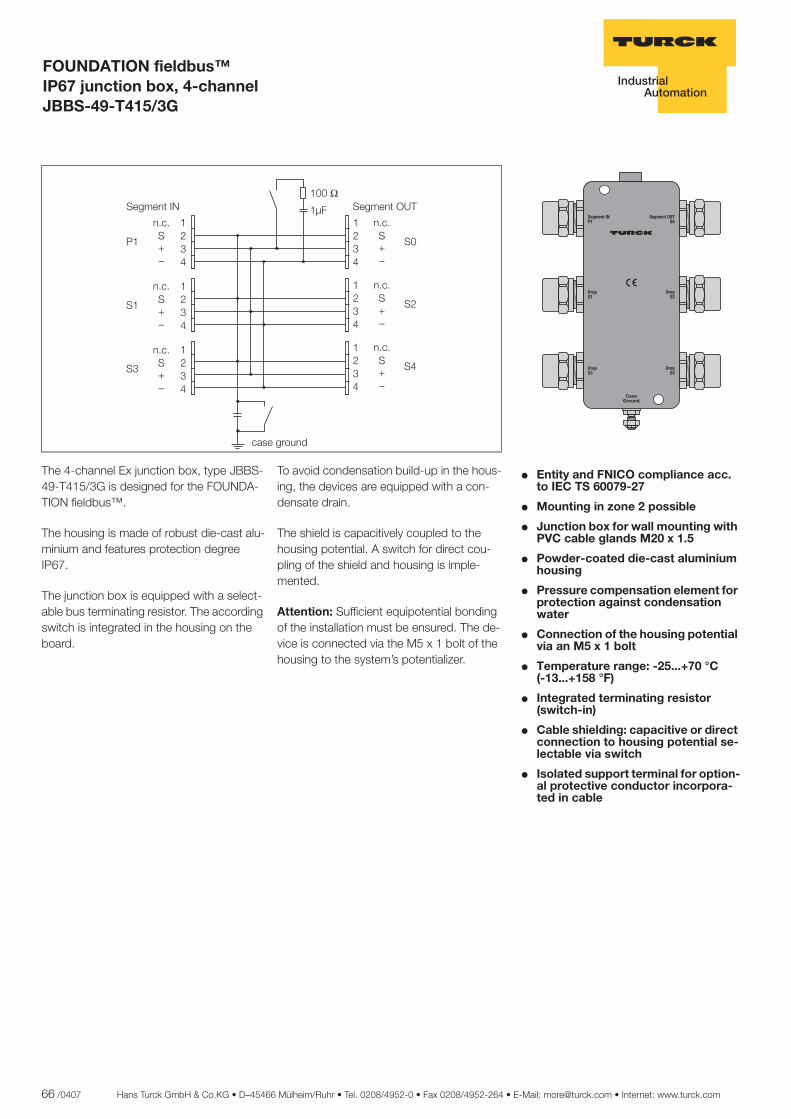
66 /0407 Hans Turck GmbH & Co.KG • D–45466 Mülheim/Ruhr • Tel. 0208/4952-0 • Fax 0208/4952-264 • E-Mail: [email protected] • Internet: www.turck.com
ñ Edition:
Hans Turck GmbH & Co.KG ñ D-45472 Mülheim an der Ruhr ñ Witzlebenstraße 7 ñ Tel. 0208 4952-0 ñ Fax 0208 4952-264 ñ [email protected] ñ www.turck.com
FOUNDATION fieldbus™ IP67 junction box, 4-channel JBBS-49-T415/3G
� Entity and FNICO compliance acc. to IEC TS 60079-27
� Mounting in zone 2 possible
� Junction box for wall mounting with PVC cable glands M20 x 1.5
� Powder-coated die-cast aluminium housing
� Pressure compensation element for protection against condensation water
� Connection of the housing potential via an M5 x 1 bolt
� Temperature range: -25...+70 °C..... (-13...+158 °F)
� Integrated terminating resistor (switch-in)
� Cable shielding: capacitive or direct connection to housing potential se-lectable via switch
� Isolated support terminal for option-al protective conductor incorpora-ted in cable
The 4-channel Ex junction box, type JBBS-49-T415/3G is designed for the FOUNDA-TION fieldbus™.
The housing is made of robust die-cast alu-minium and features protection degree IP67.
The junction box is equipped with a select-able bus terminating resistor. The according switch is integrated in the housing on the board.
To avoid condensation build-up in the hous-ing, the devices are equipped with a con-densate drain.
The shield is capacitively coupled to the housing potential. A switch for direct cou-pling of the shield and housing is imple-mented.
Attention: Sufficient equipotential bonding of the installation must be ensured. The de-vice is connected via the M5 x 1 bolt of the housing to the system’s potentializer.
����
����
���
����
��� ������
�������
��
�������
��
����
�������
��
����
�������
��
����
�������
��
����
�������
��
� �� ���� � �� ����
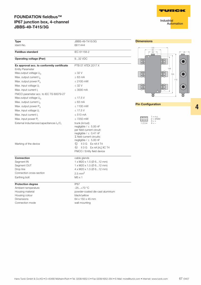
Hans Turck GmbH & Co.KG • D–45466 Mülheim/Ruhr • Tel. 0208/4952-0 • Fax 0208/4952-264 • E-Mail: [email protected] • Internet: www.turck.com 67 /0407
4
ñ Edition:
Hans Turck GmbH & Co.KG ñ D-45472 Mülheim an der Ruhr ñ Witzlebenstraße 7 ñ Tel. 0208 4952-0 ñ Fax 0208 4952-264 ñ [email protected] ñ www.turck.com
FOUNDATION fieldbus™ IP67 junction box, 4-channel JBBS-49-T415/3G
Dimensions
Pin Configuration
�������
���
��
��
��
� � � �
����������� �������������
Type JBBS-49-T415/3G Ident-No. 6611444
Fieldbus standard IEC 61158-2
Operating voltage (Pwr) 9...32 VDC
Ex approval acc. to conformity certificate PTB 07 ATEX 2017 X Entity Parameter Max.output voltage Uo ð 32 V
Max. output current Io ð 63 mA
Max. output power Po ð 2100 mW
Max. input voltage Ui ð 32 V
Max. input current Ii ð 3000 mA
FNICO parameter acc. to IEC TS 60079-27 Max.output voltage Uo ð 17.5 V
Max. output current Io ð 63 mA
Max. output power Po ð 1100 mW
Max. input voltage Ui ð 17.5 V
Max. input current Ii ð 513 mA
Max. input power Pi ð 7250 mW
External inductances/capacitances Li/Ci trunk (in/out):negligible / ð 5.00 nFper field current circuit:negligible / ð 0.47 nFæ field current circuits:negligible / ð 5.00 nF
Marking of the device É II 3 G Ex nA II T4 É II 3 G Ex nA [nL] IIC T4 FNICO / Entity field device
Connection cable glands Segment IN 1 x M20 x 1.5 (Ø 6...12 mm) Segment OUT 1 x M20 x 1.5 (Ø 6...12 mm) Drop line 4 x M20 x 1.5 (Ø 6...12 mm) Connection cross-section 2.5 mm2
Earthing bolt M5 x 1
Protection degree IP67 Ambient temperature -25...+70 °C Housing material powder-coated die-cast aluminium Housing colour black/yellow Dimensions 64 x 150 x 45 mm Connection mode wall mounting
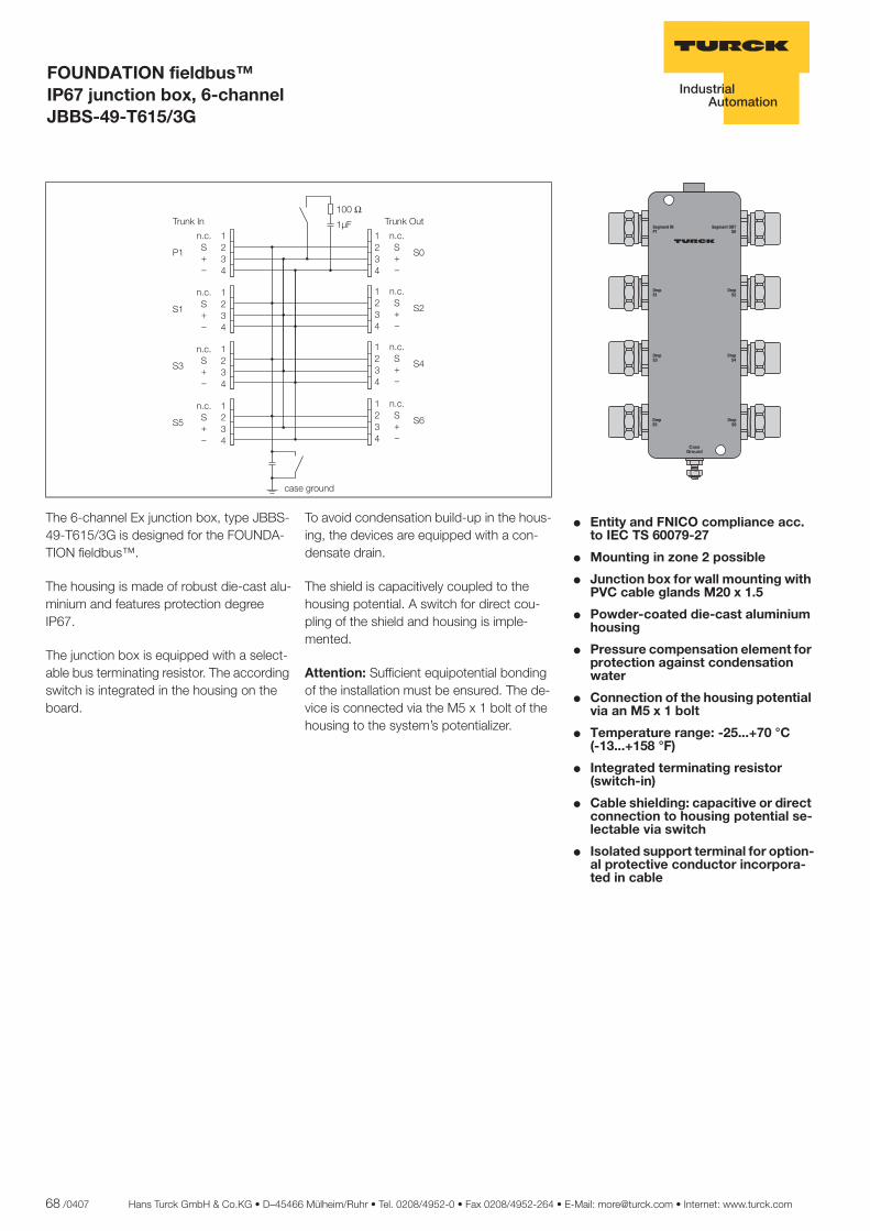
68 /0407 Hans Turck GmbH & Co.KG • D–45466 Mülheim/Ruhr • Tel. 0208/4952-0 • Fax 0208/4952-264 • E-Mail: [email protected] • Internet: www.turck.com
ñ Edition:
Hans Turck GmbH & Co.KG ñ D-45472 Mülheim an der Ruhr ñ Witzlebenstraße 7 ñ Tel. 0208 4952-0 ñ Fax 0208 4952-264 ñ [email protected] ñ www.turck.com
FOUNDATION fieldbus™ IP67 junction box, 6-channel JBBS-49-T615/3G
� Entity and FNICO compliance acc. to IEC TS 60079-27
� Mounting in zone 2 possible
� Junction box for wall mounting with PVC cable glands M20 x 1.5
� Powder-coated die-cast aluminium housing
� Pressure compensation element for protection against condensation water
� Connection of the housing potential via an M5 x 1 bolt
� Temperature range: -25...+70 °C..... (-13...+158 °F)
� Integrated terminating resistor (switch-in)
� Cable shielding: capacitive or direct connection to housing potential se-lectable via switch
� Isolated support terminal for option-al protective conductor incorpora-ted in cable
The 6-channel Ex junction box, type JBBS-49-T615/3G is designed for the FOUNDA-TION fieldbus™.
The housing is made of robust die-cast alu-minium and features protection degree IP67.
The junction box is equipped with a select-able bus terminating resistor. The according switch is integrated in the housing on the board.
To avoid condensation build-up in the hous-ing, the devices are equipped with a con-densate drain.
The shield is capacitively coupled to the housing potential. A switch for direct cou-pling of the shield and housing is imple-mented.
Attention: Sufficient equipotential bonding of the installation must be ensured. The de-vice is connected via the M5 x 1 bolt of the housing to the system’s potentializer.
����
����
���
����
��� ��
��
��� ��
�
����
��� ��
�
����
��� ��
�
����
��� ��
�
����
��� ��
�
���������
����
��� ��
�
����
��� ��
�
����� �������
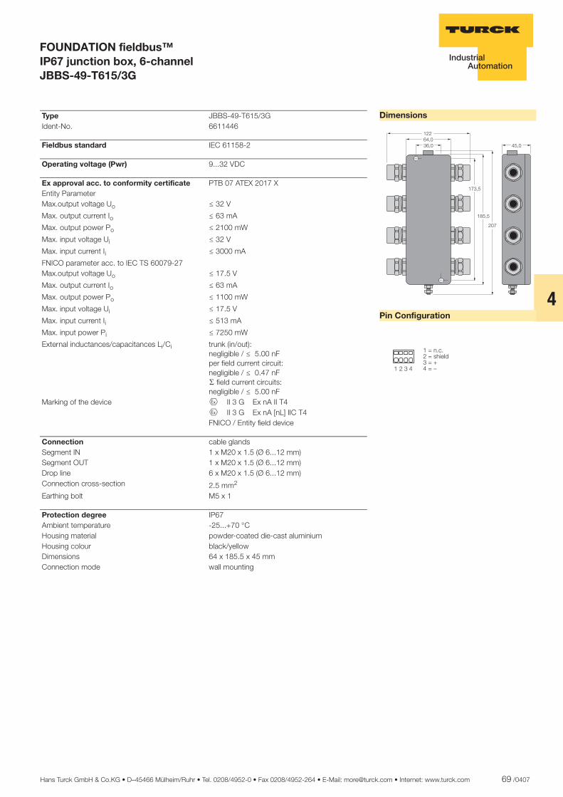
Hans Turck GmbH & Co.KG • D–45466 Mülheim/Ruhr • Tel. 0208/4952-0 • Fax 0208/4952-264 • E-Mail: [email protected] • Internet: www.turck.com 69 /0407
4
ñ Edition:
Hans Turck GmbH & Co.KG ñ D-45472 Mülheim an der Ruhr ñ Witzlebenstraße 7 ñ Tel. 0208 4952-0 ñ Fax 0208 4952-264 ñ [email protected] ñ www.turck.com
FOUNDATION fieldbus™ IP67 junction box, 6-channel JBBS-49-T615/3G
Dimensions
Pin Configuration
�����������
��
����
���
���
� � � �
��������� �������������
Type JBBS-49-T615/3G Ident-No. 6611446
Fieldbus standard IEC 61158-2
Operating voltage (Pwr) 9...32 VDC
Ex approval acc. to conformity certificate PTB 07 ATEX 2017 X Entity Parameter Max.output voltage Uo ð 32 V
Max. output current Io ð 63 mA
Max. output power Po ð 2100 mW
Max. input voltage Ui ð 32 V
Max. input current Ii ð 3000 mA
FNICO parameter acc. to IEC TS 60079-27 Max.output voltage Uo ð 17.5 V
Max. output current Io ð 63 mA
Max. output power Po ð 1100 mW
Max. input voltage Ui ð 17.5 V
Max. input current Ii ð 513 mA
Max. input power Pi ð 7250 mW
External inductances/capacitances Li/Ci trunk (in/out):negligible / ð 5.00 nFper field current circuit:negligible / ð 0.47 nFæ field current circuits:negligible / ð 5.00 nF
Marking of the device É II 3 G Ex nA II T4 É II 3 G Ex nA [nL] IIC T4 FNICO / Entity field device
Connection cable glands Segment IN 1 x M20 x 1.5 (Ø 6...12 mm) Segment OUT 1 x M20 x 1.5 (Ø 6...12 mm) Drop line 6 x M20 x 1.5 (Ø 6...12 mm) Connection cross-section 2.5 mm2
Earthing bolt M5 x 1
Protection degree IP67 Ambient temperature -25...+70 °C Housing material powder-coated die-cast aluminium Housing colour black/yellow Dimensions 64 x 185.5 x 45 mm Connection mode wall mounting
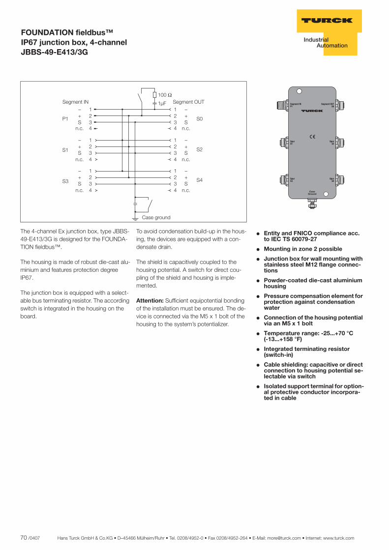
70 /0407 Hans Turck GmbH & Co.KG • D–45466 Mülheim/Ruhr • Tel. 0208/4952-0 • Fax 0208/4952-264 • E-Mail: [email protected] • Internet: www.turck.com
ñ Edition:
Hans Turck GmbH & Co.KG ñ D-45472 Mülheim an der Ruhr ñ Witzlebenstraße 7 ñ Tel. 0208 4952-0 ñ Fax 0208 4952-264 ñ [email protected] ñ www.turck.com
FOUNDATION fieldbus™ IP67 junction box, 4-channel JBBS-49-E413/3G
� Entity and FNICO compliance acc. to IEC TS 60079-27
� Mounting in zone 2 possible
� Junction box for wall mounting with stainless steel M12 flange connec-tions
� Powder-coated die-cast aluminium housing
� Pressure compensation element for protection against condensation water
� Connection of the housing potential via an M5 x 1 bolt
� Temperature range: -25...+70 °C..... (-13...+158 °F)
� Integrated terminating resistor (switch-in)
� Cable shielding: capacitive or direct connection to housing potential se-lectable via switch
� Isolated support terminal for option-al protective conductor incorpora-ted in cable
�� �
�� �
�� �
�� �
�����������
�����������
��������
The 4-channel Ex junction box, type JBBS-49-E413/3G is designed for the FOUNDA-TION fieldbus™.
The housing is made of robust die-cast alu-minium and features protection degree IP67.
The junction box is equipped with a select-able bus terminating resistor. The according switch is integrated in the housing on the board.
To avoid condensation build-up in the hous-ing, the devices are equipped with a con-densate drain.
The shield is capacitively coupled to the housing potential. A switch for direct cou-pling of the shield and housing is imple-mented.
Attention: Sufficient equipotential bonding of the installation must be ensured. The de-vice is connected via the M5 x 1 bolt of the housing to the system’s potentializer.
����
����
���
����
�� ������
�������
�� ��
����
��
����
��
����
��
����
��
�������
�������
�������
�������
�������
� �� ���� � �� ����
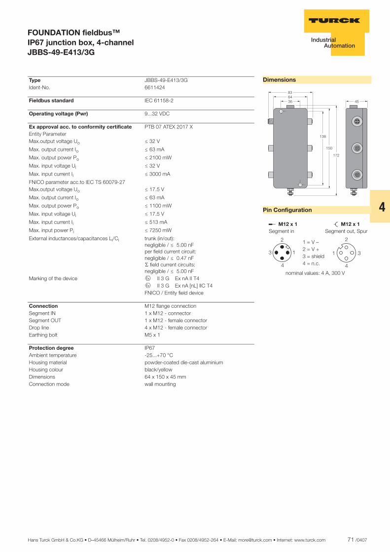
Hans Turck GmbH & Co.KG • D–45466 Mülheim/Ruhr • Tel. 0208/4952-0 • Fax 0208/4952-264 • E-Mail: [email protected] • Internet: www.turck.com 71 /0407
4
ñ Edition:
Hans Turck GmbH & Co.KG ñ D-45472 Mülheim an der Ruhr ñ Witzlebenstraße 7 ñ Tel. 0208 4952-0 ñ Fax 0208 4952-264 ñ [email protected] ñ www.turck.com
FOUNDATION fieldbus™ IP67 junction box, 4-channel JBBS-49-E413/3G
Dimensions
Pin Configuration
������
���
���
�
��
������� �������
�
� �
�
�
�
�
�
������ ���������������
� ���������������������
�������������������� ������� !
Type JBBS-49-E413/3G Ident-No. 6611424
Fieldbus standard IEC 61158-2
Operating voltage (Pwr) 9...32 VDC
Ex approval acc. to conformity certificate PTB 07 ATEX 2017 X Entity Parameter Max.output voltage Uo ð 32 V
Max. output current Io ð 63 mA
Max. output power Po ð 2100 mW
Max. input voltage Ui ð 32 V
Max. input current Ii ð 3000 mA
FNICO parameter acc.to IEC TS 60079-27 Max.output voltage Uo ð 17.5 V
Max. output current Io ð 63 mA
Max. output power Po ð 1100 mW
Max. input voltage Ui ð 17.5 V
Max. input current Ii ð 513 mA
Max. input power Pi ð 7250 mW
External inductances/capacitances Li/Ci trunk (in/out):negligible / ð 5.00 nFper field current circuit:negligible / ð 0.47 nFæ field current circuits:negligible / ð 5.00 nF
Marking of the device É II 3 G Ex nA II T4 É II 3 G Ex nA [nL] IIC T4 FNICO / Entity field device
Connection M12 flange connection Segment IN 1 x M12 - connector Segment OUT 1 x M12 - female connector Drop line 4 x M12 - female connector Earthing bolt M5 x 1
Protection degree IP67 Ambient temperature -25...+70 °C Housing material powder-coated die-cast aluminium Housing colour black/yellow Dimensions 64 x 150 x 45 mm Connection mode wall mounting
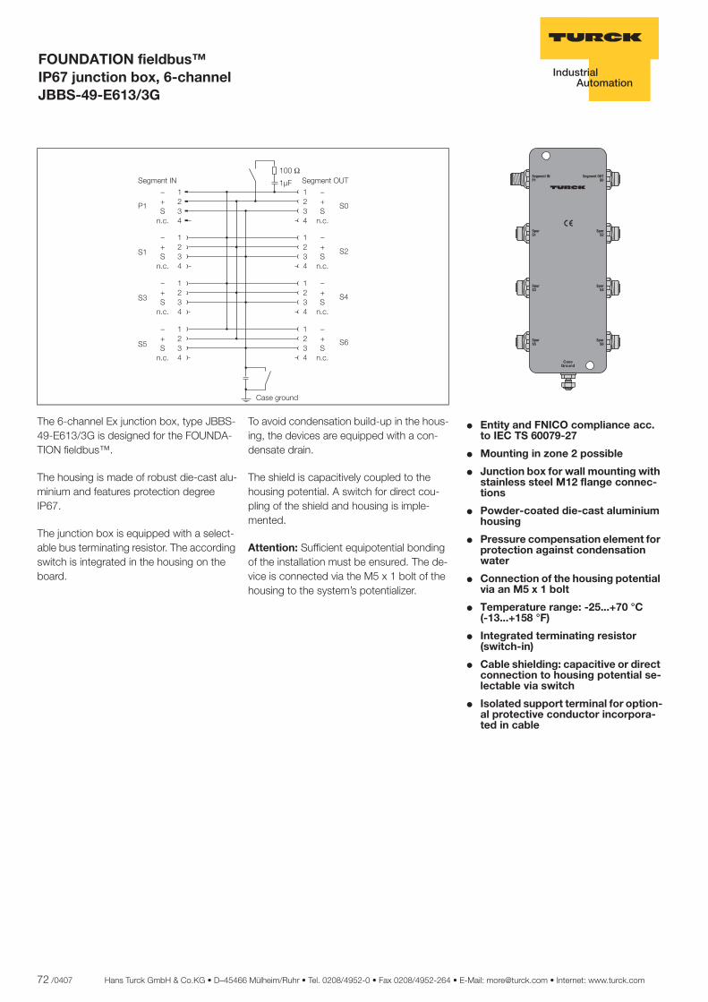
72 /0407 Hans Turck GmbH & Co.KG • D–45466 Mülheim/Ruhr • Tel. 0208/4952-0 • Fax 0208/4952-264 • E-Mail: [email protected] • Internet: www.turck.com
ñ Edition:
Hans Turck GmbH & Co.KG ñ D-45472 Mülheim an der Ruhr ñ Witzlebenstraße 7 ñ Tel. 0208 4952-0 ñ Fax 0208 4952-264 ñ [email protected] ñ www.turck.com
FOUNDATION fieldbus™ IP67 junction box, 6-channel JBBS-49-E613/3G
� Entity and FNICO compliance acc. to IEC TS 60079-27
� Mounting in zone 2 possible
� Junction box for wall mounting with stainless steel M12 flange connec-tions
� Powder-coated die-cast aluminium housing
� Pressure compensation element for protection against condensation water
� Connection of the housing potential via an M5 x 1 bolt
� Temperature range: -25...+70 °C..... (-13...+158 °F)
� Integrated terminating resistor (switch-in)
� Cable shielding: capacitive or direct connection to housing potential se-lectable via switch
� Isolated support terminal for option-al protective conductor incorpora-ted in cable
������
������
������
�����
��� ������
��� �������
��������
������
������
The 6-channel Ex junction box, type JBBS-49-E613/3G is designed for the FOUNDA-TION fieldbus™.
The housing is made of robust die-cast alu-minium and features protection degree IP67.
The junction box is equipped with a select-able bus terminating resistor. The according switch is integrated in the housing on the board.
To avoid condensation build-up in the hous-ing, the devices are equipped with a con-densate drain.
The shield is capacitively coupled to the housing potential. A switch for direct cou-pling of the shield and housing is imple-mented.
Attention: Sufficient equipotential bonding of the installation must be ensured. The de-vice is connected via the M5 x 1 bolt of the housing to the system’s potentializer.
����
����
���
����
�� ������
�������
�� ��
����
��
����
��
�������
����
��
����
��
�������
����
��
����
��
�������
�������
�������
�������
�������
� �� ���� � �� �� !"
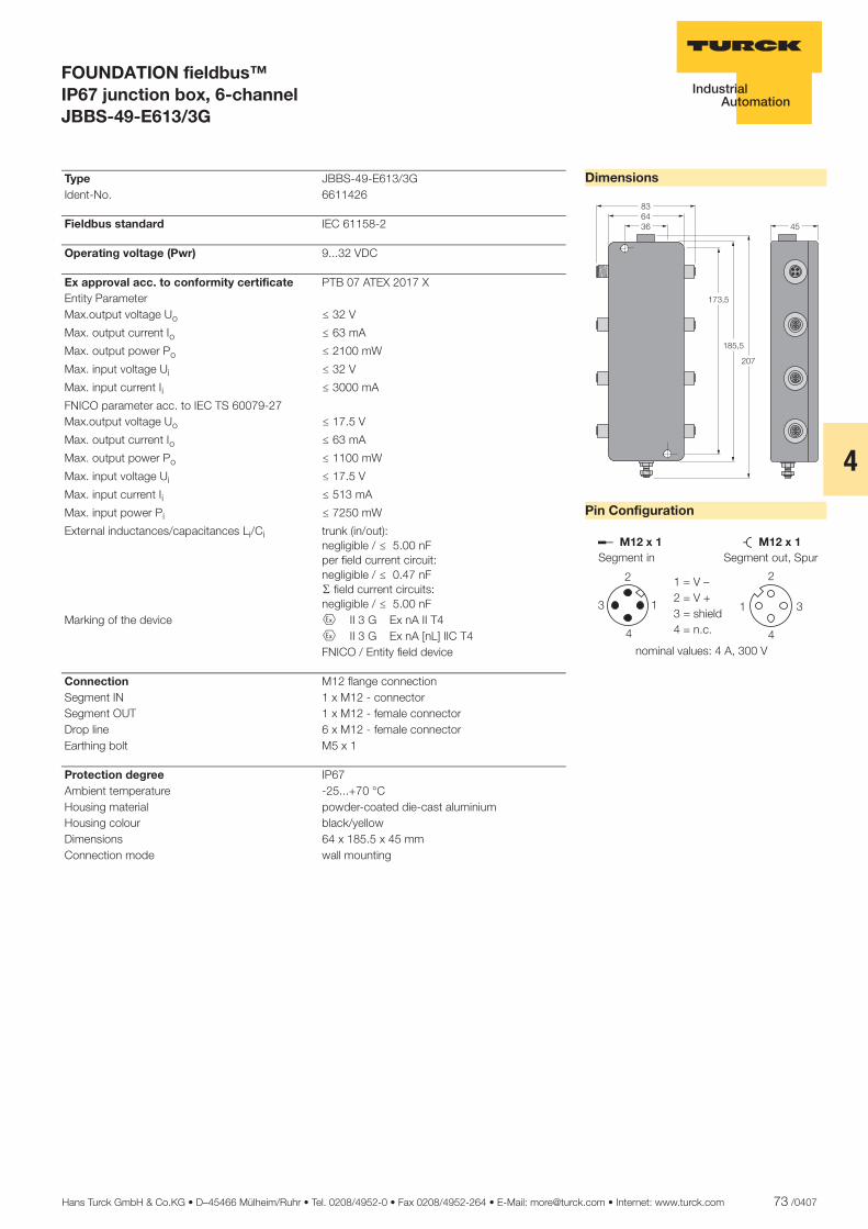
Hans Turck GmbH & Co.KG • D–45466 Mülheim/Ruhr • Tel. 0208/4952-0 • Fax 0208/4952-264 • E-Mail: [email protected] • Internet: www.turck.com 73 /0407
4
ñ Edition:
Hans Turck GmbH & Co.KG ñ D-45472 Mülheim an der Ruhr ñ Witzlebenstraße 7 ñ Tel. 0208 4952-0 ñ Fax 0208 4952-264 ñ [email protected] ñ www.turck.com
FOUNDATION fieldbus™ IP67 junction box, 6-channel JBBS-49-E613/3G
Dimensions
Pin Configuration
������
�����
����
��
�
������� �������
�
� �
�
�
�
�
�
������ ���������������
� ���������������������
�������������������� ������� !
Type JBBS-49-E613/3G Ident-No. 6611426
Fieldbus standard IEC 61158-2
Operating voltage (Pwr) 9...32 VDC
Ex approval acc. to conformity certificate PTB 07 ATEX 2017 X Entity Parameter Max.output voltage Uo ð 32 V
Max. output current Io ð 63 mA
Max. output power Po ð 2100 mW
Max. input voltage Ui ð 32 V
Max. input current Ii ð 3000 mA
FNICO parameter acc. to IEC TS 60079-27 Max.output voltage Uo ð 17.5 V
Max. output current Io ð 63 mA
Max. output power Po ð 1100 mW
Max. input voltage Ui ð 17.5 V
Max. input current Ii ð 513 mA
Max. input power Pi ð 7250 mW
External inductances/capacitances Li/Ci trunk (in/out):negligible / ð 5.00 nFper field current circuit:negligible / ð 0.47 nFæ field current circuits:negligible / ð 5.00 nF
Marking of the device É II 3 G Ex nA II T4 É II 3 G Ex nA [nL] IIC T4 FNICO / Entity field device
Connection M12 flange connection Segment IN 1 x M12 - connector Segment OUT 1 x M12 - female connector Drop line 6 x M12 - female connector Earthing bolt M5 x 1
Protection degree IP67 Ambient temperature -25...+70 °C Housing material powder-coated die-cast aluminium Housing colour black/yellow Dimensions 64 x 185.5 x 45 mm Connection mode wall mounting
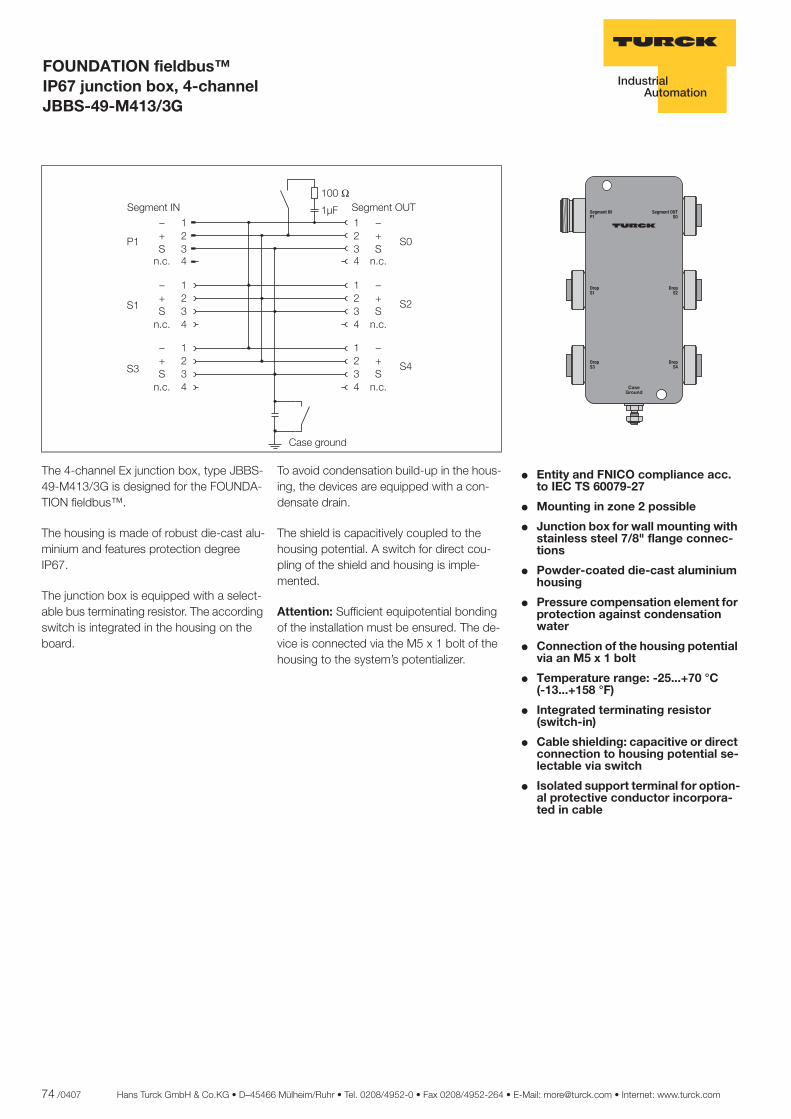
74 /0407 Hans Turck GmbH & Co.KG • D–45466 Mülheim/Ruhr • Tel. 0208/4952-0 • Fax 0208/4952-264 • E-Mail: [email protected] • Internet: www.turck.com
ñ Edition:
Hans Turck GmbH & Co.KG ñ D-45472 Mülheim an der Ruhr ñ Witzlebenstraße 7 ñ Tel. 0208 4952-0 ñ Fax 0208 4952-264 ñ [email protected] ñ www.turck.com
FOUNDATION fieldbus™ IP67 junction box, 4-channel JBBS-49-M413/3G
� Entity and FNICO compliance acc. to IEC TS 60079-27
� Mounting in zone 2 possible
� Junction box for wall mounting with stainless steel 7/8" flange connec-tions
� Powder-coated die-cast aluminium housing
� Pressure compensation element for protection against condensation water
� Connection of the housing potential via an M5 x 1 bolt
� Temperature range: -25...+70 °C..... (-13...+158 °F)
� Integrated terminating resistor (switch-in)
� Cable shielding: capacitive or direct connection to housing potential se-lectable via switch
� Isolated support terminal for option-al protective conductor incorpora-ted in cable
������
������
�����
�����
��� ��������
��� ���������
��������
The 4-channel Ex junction box, type JBBS-49-M413/3G is designed for the FOUNDA-TION fieldbus™.
The housing is made of robust die-cast alu-minium and features protection degree IP67.
The junction box is equipped with a select-able bus terminating resistor. The according switch is integrated in the housing on the board.
To avoid condensation build-up in the hous-ing, the devices are equipped with a con-densate drain.
The shield is capacitively coupled to the housing potential. A switch for direct cou-pling of the shield and housing is imple-mented.
Attention: Sufficient equipotential bonding of the installation must be ensured. The de-vice is connected via the M5 x 1 bolt of the housing to the system’s potentializer.
����
����
���
����
�� ������
�������
�� ��
����
��
����
��
����
��
����
��
�������
�������
�������
�������
�������
� �� ���� � �� ����

Hans Turck GmbH & Co.KG • D–45466 Mülheim/Ruhr • Tel. 0208/4952-0 • Fax 0208/4952-264 • E-Mail: [email protected] • Internet: www.turck.com 75 /0407
4
ñ Edition:
Hans Turck GmbH & Co.KG ñ D-45472 Mülheim an der Ruhr ñ Witzlebenstraße 7 ñ Tel. 0208 4952-0 ñ Fax 0208 4952-264 ñ [email protected] ñ www.turck.com
FOUNDATION fieldbus™ IP67 junction box, 4-channel JBBS-49-M413/3G
Dimensions
Pin Configuration
��
������
���
��
��
��� ����
�
�
�
�
�
�
�
�
���������������������� �
�
�
�
�
�
�
�
�
��� ���������� ��!!"
�#"��#�$%$�#"��#�& ��'
Type JBBS-49-M413/3G Ident-No. 6611428
Fieldbus standard IEC 61158-2
Operating voltage (Pwr) 9...32 VDC
Ex approval acc. to conformity certificate PTB 07 ATEX 2017 X Entity Parameter Max.output voltage Uo ð 32 V
Max. output current Io ð 63 mA
Max. output power Po ð 2100 mW
Max. input voltage Ui ð 32 V
Max. input current Ii ð 3000 mA
FNICO parameter acc. to IEC TS 60079-27 Max.output voltage Uo ð 17.5 V
Max. output current Io ð 63 mA
Max. output power Po ð 1100 mW
Max. input voltage Ui ð 17.5 V
Max. input current Ii ð 513 mA
Max. input power Pi ð 7250 mW
External inductances/capacitances Li/Ci trunk (in/out):negligible / ð 5.00 nFper field current circuit:negligible / ð 0.47 nFæ field current circuits:negligible / ð 5.00 nF
Marking of the device É II 3 G Ex nA II T4 É II 3 G Ex nA [nL] IIC T4 FNICO / Entity field device
Connection 7/8" flange connection Segment IN 1 x 7/8 "- plug Segment OUT 1 x 7/8 "- coupling Drop line 4 x 7/8 "- plug Earthing bolt M5 x 1
Protection degree IP67 Ambient temperature -25...+70 °C Housing material powder-coated die-cast aluminium Housing colour black/yellow Dimensions 64 x 150 x 45 mm Connection mode wall mounting
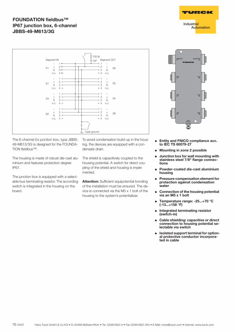
76 /0407 Hans Turck GmbH & Co.KG • D–45466 Mülheim/Ruhr • Tel. 0208/4952-0 • Fax 0208/4952-264 • E-Mail: [email protected] • Internet: www.turck.com
ñ Edition:
Hans Turck GmbH & Co.KG ñ D-45472 Mülheim an der Ruhr ñ Witzlebenstraße 7 ñ Tel. 0208 4952-0 ñ Fax 0208 4952-264 ñ [email protected] ñ www.turck.com
FOUNDATION fieldbus™ IP67 junction box, 6-channel JBBS-49-M613/3G
� Entity and FNICO compliance acc. to IEC TS 60079-27
� Mounting in zone 2 possible
� Junction box for wall mounting with stainless steel 7/8" flange connec-tions
� Powder-coated die-cast aluminium housing
� Pressure compensation element for protection against condensation water
� Connection of the housing potential via an M5 x 1 bolt
� Temperature range: -25...+70 °C..... (-13...+158 °F)
� Integrated terminating resistor (switch-in)
� Cable shielding: capacitive or direct connection to housing potential se-lectable via switch
� Isolated support terminal for option-al protective conductor incorpora-ted in cable
������
������
�����
�����
��� ��������
��� ���������
��������
������
������
The 6-channel Ex junction box, type JBBS-49-M613/3G is designed for the FOUNDA-TION fieldbus™.
The housing is made of robust die-cast alu-minium and features protection degree IP67.
The junction box is equipped with a select-able bus terminating resistor. The according switch is integrated in the housing on the board.
To avoid condensation build-up in the hous-ing, the devices are equipped with a con-densate drain.
The shield is capacitively coupled to the housing potential. A switch for direct cou-pling of the shield and housing is imple-mented.
Attention: Sufficient equipotential bonding of the installation must be ensured. The de-vice is connected via the M5 x 1 bolt of the housing to the system’s potentializer.
����
����
���
����
�� ������
�������
�� ��
����
��
����
��
�������
����
��
����
��
�������
����
��
����
��
�������
�������
�������
�������
�������
� �� ���� � �� �� !"

Hans Turck GmbH & Co.KG • D–45466 Mülheim/Ruhr • Tel. 0208/4952-0 • Fax 0208/4952-264 • E-Mail: [email protected] • Internet: www.turck.com 77 /0407
4
ñ Edition:
Hans Turck GmbH & Co.KG ñ D-45472 Mülheim an der Ruhr ñ Witzlebenstraße 7 ñ Tel. 0208 4952-0 ñ Fax 0208 4952-264 ñ [email protected] ñ www.turck.com
FOUNDATION fieldbus™ IP67 junction box, 6-channel JBBS-49-M613/3G
Dimensions
Pin Configuration
������ ��
����
���
��
��� �������������
�
�
�
�
�����������������
�������������������������
��������������������� ����!"!
Type JBBS-49-M613/3G Ident-No. 6611430
Fieldbus standard IEC 61158-2
Operating voltage (Pwr) 9...32 VDC
Ex approval acc. to conformity certificate PTB 07 ATEX 2017 X Entity Parameter Max.output voltage Uo ð 32 V
Max. output current Io ð 63 mA
Max. output power Po ð 2100 mW
Max. input voltage Ui ð 32 V
Max. input current Ii ð 3000 mA
FNICO parameter acc. to IEC TS 60079-27 Max.output voltage Uo ð 17.5 V
Max. output current Io ð 63 mA
Max. output power Po ð 1100 mW
Max. input voltage Ui ð 17.5 V
Max. input current Ii ð 513 mA
Max. input power Pi ð 7250 mW
External inductances/capacitances Li/Ci trunk (in/out):negligible / ð 5.00 nFper field current circuit:negligible / ð 0.47 nFæ field current circuits:negligible / ð 5.00 nF
Marking of the device É II 3 G Ex nA II T4 É II 3 G Ex nA [nL] IIC T4 FNICO / Entity field device
Connection 7/8" flange connection Segment IN 1 x 7/8 "- plug Segment OUT 1 x 7/8 "- coupling Drop line 6 x 7/8 "- plug Earthing bolt M5 x 1
Protection degree IP67 Ambient temperature -25...+70 °C Housing material powder-coated die-cast aluminium Housing colour black/yellow Dimensions 64 x 185.5 x 45 mm Connection mode wall mounting
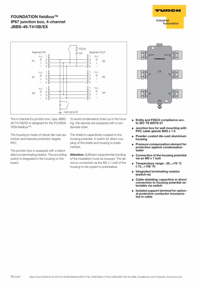
78 /0407 Hans Turck GmbH & Co.KG • D–45466 Mülheim/Ruhr • Tel. 0208/4952-0 • Fax 0208/4952-264 • E-Mail: [email protected] • Internet: www.turck.com
ñ Edition:
Hans Turck GmbH & Co.KG ñ D-45472 Mülheim an der Ruhr ñ Witzlebenstraße 7 ñ Tel. 0208 4952-0 ñ Fax 0208 4952-264 ñ [email protected] ñ www.turck.com
FOUNDATION fieldbus™ IP67 junction box, 4-channel JBBS-49-T415B/EX
� Entity and FISCO compliance acc. to IEC TS 60079-27
� Junction box for wall mounting with PVC cable glands M20 x 1.5
� Powder-coated die-cast aluminium housing
� Pressure compensation element for protection against condensation water
� Connection of the housing potential via an M5 x 1 bolt
� Temperature range: -25...+70 °C..... (-13...+158 °F)
� Integrated terminating resistor (switch-in)
� Cable shielding: capacitive or direct connection to housing potential se-lectable via switch
� Isolated support terminal for option-al protective conductor incorpora-ted in cable
The 4-channel Ex junction box, type JBBS-49-T415B/EX is designed for the FOUNDA-TION fieldbus™.
The housing is made of robust die-cast alu-minium and features protection degree IP67.
The junction box is equipped with a select-able bus terminating resistor. The according switch is integrated in the housing on the board.
To avoid condensation build-up in the hous-ing, the devices are equipped with a con-densate drain.
The shield is capacitively coupled to the housing potential. A switch for direct cou-pling of the shield and housing is imple-mented.
Attention: Sufficient equipotential bonding of the installation must be ensured. The de-vice is connected via the M5 x 1 bolt of the housing to the system’s potentializer.
����
����
���
����
�� ������
������
��
������
��
����
������
��
����
������
��
����
������
��
����
������
��
� �� ���� � �� �����
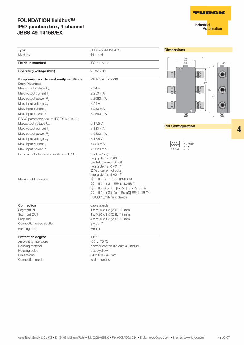
Hans Turck GmbH & Co.KG • D–45466 Mülheim/Ruhr • Tel. 0208/4952-0 • Fax 0208/4952-264 • E-Mail: [email protected] • Internet: www.turck.com 79 /0407
4
ñ Edition:
Hans Turck GmbH & Co.KG ñ D-45472 Mülheim an der Ruhr ñ Witzlebenstraße 7 ñ Tel. 0208 4952-0 ñ Fax 0208 4952-264 ñ [email protected] ñ www.turck.com
FOUNDATION fieldbus™ IP67 junction box, 4-channel JBBS-49-T415B/EX
Dimensions
Pin Configuration
�������
���
��
��
��
� � � �
����������� �������������
Type JBBS-49-T415B/EX Ident-No. 6611445
Fieldbus standard IEC 61158-2
Operating voltage (Pwr) 9...32 VDC
Ex approval acc. to conformity certificate PTB 03 ATEX 2236 Entity Parameter Max.output voltage Uo ð 24 V
Max. output current Io ð 250 mA
Max. output power Po ð 2560 mW
Max. input voltage Ui ð 24 V
Max. input current Ii ð 250 mA
Max. input power Pi ð 2560 mW
FISCO parameter acc. to IEC TS 60079-27 Max.output voltage Uo ð 17.5 V
Max. output current Io ð 380 mA
Max. output power Po ð 5320 mW
Max. input voltage Ui ð 17.5 V
Max. input current Ii ð 380 mA
Max. input power Pi ð 5320 mW
External inductances/capacitances Li/Ci trunk (in/out):negligible / ð 5.00 nFper field current circuit:negligible / ð 0.47 nFæ field current circuits:negligible / ð 5.00 nF
Marking of the device É II 2 G EEx ib IIC/IIB T4 É II 2 (1) G EEx ia IIC/IIB T4 É II 2 G (2D) [Ex ibD] EEx ib IIB T4 É II 2 (1) G (1D) [Ex iaD] EEx ia IIB T4 FISCO / Entity field device
Connection cable glands Segment IN 1 x M20 x 1.5 (Ø 6...12 mm) Segment OUT 1 x M20 x 1.5 (Ø 6...12 mm) Drop line 4 x M20 x 1.5 (Ø 6...12 mm) Connection cross-section 2.5 mm2
Earthing bolt M5 x 1
Protection degree IP67 Ambient temperature -25...+70 °C Housing material powder-coated die-cast aluminium Housing colour black/yellow Dimensions 64 x 150 x 45 mm Connection mode wall mounting
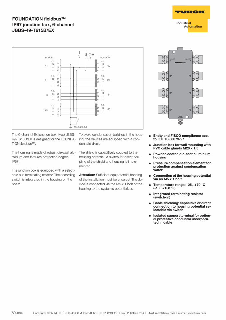
80 /0407 Hans Turck GmbH & Co.KG • D–45466 Mülheim/Ruhr • Tel. 0208/4952-0 • Fax 0208/4952-264 • E-Mail: [email protected] • Internet: www.turck.com
ñ Edition:
Hans Turck GmbH & Co.KG ñ D-45472 Mülheim an der Ruhr ñ Witzlebenstraße 7 ñ Tel. 0208 4952-0 ñ Fax 0208 4952-264 ñ [email protected] ñ www.turck.com
FOUNDATION fieldbus™ IP67 junction box, 6-channel JBBS-49-T615B/EX
� Entity and FISCO compliance acc. to IEC TS 60079-27
� Junction box for wall mounting with PVC cable glands M20 x 1.5
� Powder-coated die-cast aluminium housing
� Pressure compensation element for protection against condensation water
� Connection of the housing potential via an M5 x 1 bolt
� Temperature range: -25...+70 °C..... (-13...+158 °F)
� Integrated terminating resistor (switch-in)
� Cable shielding: capacitive or direct connection to housing potential se-lectable via switch
� Isolated support terminal for option-al protective conductor incorpora-ted in cable
The 6-channel Ex junction box, type JBBS-49-T615B/EX is designed for the FOUNDA-TION fieldbus™.
The housing is made of robust die-cast alu-minium and features protection degree IP67.
The junction box is equipped with a select-able bus terminating resistor. The according switch is integrated in the housing on the board.
To avoid condensation build-up in the hous-ing, the devices are equipped with a con-densate drain.
The shield is capacitively coupled to the housing potential. A switch for direct cou-pling of the shield and housing is imple-mented.
Attention: Sufficient equipotential bonding of the installation must be ensured. The de-vice is connected via the M5 x 1 bolt of the housing to the system’s potentializer.
����
����
���
�����
����
��
����
��
����
����
��
����
����
��
����
����
��
����
����
��
����������
����
����
��
����
����
��
���� �!� ���� �"�#
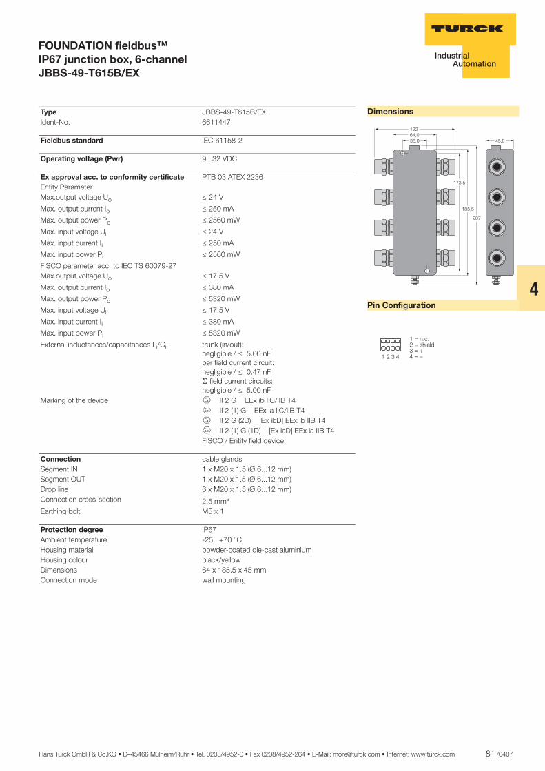
Hans Turck GmbH & Co.KG • D–45466 Mülheim/Ruhr • Tel. 0208/4952-0 • Fax 0208/4952-264 • E-Mail: [email protected] • Internet: www.turck.com 81 /0407
4
ñ Edition:
Hans Turck GmbH & Co.KG ñ D-45472 Mülheim an der Ruhr ñ Witzlebenstraße 7 ñ Tel. 0208 4952-0 ñ Fax 0208 4952-264 ñ [email protected] ñ www.turck.com
FOUNDATION fieldbus™ IP67 junction box, 6-channel JBBS-49-T615B/EX
Dimensions
Pin Configuration
�����������
��
����
���
���
� � � �
����������� �������������
Type JBBS-49-T615B/EX Ident-No. 6611447
Fieldbus standard IEC 61158-2
Operating voltage (Pwr) 9...32 VDC
Ex approval acc. to conformity certificate PTB 03 ATEX 2236 Entity Parameter Max.output voltage Uo ð 24 V
Max. output current Io ð 250 mA
Max. output power Po ð 2560 mW
Max. input voltage Ui ð 24 V
Max. input current Ii ð 250 mA
Max. input power Pi ð 2560 mW
FISCO parameter acc. to IEC TS 60079-27 Max.output voltage Uo ð 17.5 V
Max. output current Io ð 380 mA
Max. output power Po ð 5320 mW
Max. input voltage Ui ð 17.5 V
Max. input current Ii ð 380 mA
Max. input power Pi ð 5320 mW
External inductances/capacitances Li/Ci trunk (in/out):negligible / ð 5.00 nFper field current circuit:negligible / ð 0.47 nFæ field current circuits:negligible / ð 5.00 nF
Marking of the device É II 2 G EEx ib IIC/IIB T4 É II 2 (1) G EEx ia IIC/IIB T4 É II 2 G (2D) [Ex ibD] EEx ib IIB T4 É II 2 (1) G (1D) [Ex iaD] EEx ia IIB T4 FISCO / Entity field device
Connection cable glands Segment IN 1 x M20 x 1.5 (Ø 6...12 mm) Segment OUT 1 x M20 x 1.5 (Ø 6...12 mm) Drop line 6 x M20 x 1.5 (Ø 6...12 mm) Connection cross-section 2.5 mm2
Earthing bolt M5 x 1
Protection degree IP67 Ambient temperature -25...+70 °C Housing material powder-coated die-cast aluminium Housing colour black/yellow Dimensions 64 x 185.5 x 45 mm Connection mode wall mounting
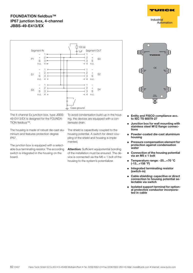
82 /0407 Hans Turck GmbH & Co.KG • D–45466 Mülheim/Ruhr • Tel. 0208/4952-0 • Fax 0208/4952-264 • E-Mail: [email protected] • Internet: www.turck.com
ñ Edition:
Hans Turck GmbH & Co.KG ñ D-45472 Mülheim an der Ruhr ñ Witzlebenstraße 7 ñ Tel. 0208 4952-0 ñ Fax 0208 4952-264 ñ [email protected] ñ www.turck.com
FOUNDATION fieldbus™ IP67 junction box, 4-channel JBBS-49-E413/EX
� Entity and FISCO compliance acc. to IEC TS 60079-27
� Junction box for wall mounting with stainless steel M12 flange connec-tions
� Powder-coated die-cast aluminium housing
� Pressure compensation element for protection against condensation water
� Connection of the housing potential via an M5 x 1 bolt
� Temperature range: -25...+70 °C..... (-13...+158 °F)
� Integrated terminating resistor (switch-in)
� Cable shielding: capacitive or direct connection to housing potential se-lectable via switch
� Isolated support terminal for option-al protective conductor incorpora-ted in cable
������
������
������
�����
��� ������
��� �������
��������
The 4-channel Ex junction box, type JBBS-49-E413/EX is designed for the FOUNDA-TION fieldbus™.
The housing is made of robust die-cast alu-minium and features protection degree IP67.
The junction box is equipped with a select-able bus terminating resistor. The according switch is integrated in the housing on the board.
To avoid condensation build-up in the hous-ing, the devices are equipped with a con-densate drain.
The shield is capacitively coupled to the housing potential. A switch for direct cou-pling of the shield and housing is imple-mented.
Attention: Sufficient equipotential bonding of the installation must be ensured. The de-vice is connected via the M5 x 1 bolt of the housing to the system’s potentializer.
����
����
���
����
�� ������
�������
�� ��
����
��
����
��
����
��
����
��
�������
�������
�������
�������
�������
� �� ���� � �� ����
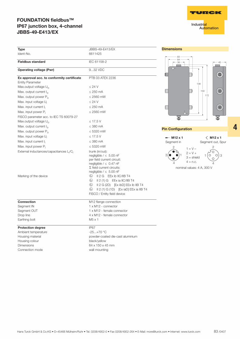
Hans Turck GmbH & Co.KG • D–45466 Mülheim/Ruhr • Tel. 0208/4952-0 • Fax 0208/4952-264 • E-Mail: [email protected] • Internet: www.turck.com 83 /0407
4
ñ Edition:
Hans Turck GmbH & Co.KG ñ D-45472 Mülheim an der Ruhr ñ Witzlebenstraße 7 ñ Tel. 0208 4952-0 ñ Fax 0208 4952-264 ñ [email protected] ñ www.turck.com
FOUNDATION fieldbus™ IP67 junction box, 4-channel JBBS-49-E413/EX
Dimensions
Pin Configuration
������
���
���
�
��
������� �������
�
� �
�
�
�
�
�
������ ���������������
� ���������������������
�������������������� ������� !
Type JBBS-49-E413/EX Ident-No. 6611425
Fieldbus standard IEC 61158-2
Operating voltage (Pwr) 9...32 VDC
Ex approval acc. to conformity certificate PTB 03 ATEX 2236 Entity Parameter Max.output voltage Uo ð 24 V
Max. output current Io ð 250 mA
Max. output power Po ð 2560 mW
Max. input voltage Ui ð 24 V
Max. input current Ii ð 250 mA
Max. input power Pi ð 2560 mW
FISCO parameter acc. to IEC TS 60079-27 Max.output voltage Uo ð 17.5 V
Max. output current Io ð 380 mA
Max. output power Po ð 5320 mW
Max. input voltage Ui ð 17.5 V
Max. input current Ii ð 380 mA
Max. input power Pi ð 5320 mW
External inductances/capacitances Li/Ci trunk (in/out):negligible / ð 5.00 nFper field current circuit:negligible / ð 0.47 nFæ field current circuits:negligible / ð 5.00 nF
Marking of the device É II 2 G EEx ib IIC/IIB T4 É II 2 (1) G EEx ia IIC/IIB T4 É II 2 G (2D) [Ex ibD] EEx ib IIB T4 É II 2 (1) G (1D) [Ex iaD] EEx ia IIB T4 FISCO / Entity field device
Connection M12 flange connection Segment IN 1 x M12 - connector Segment OUT 1 x M12 - female connector Drop line 4 x M12 - female connector Earthing bolt M5 x 1
Protection degree IP67 Ambient temperature -25...+70 °C Housing material powder-coated die-cast aluminium Housing colour black/yellow Dimensions 64 x 150 x 45 mm Connection mode wall mounting

84 /0407 Hans Turck GmbH & Co.KG • D–45466 Mülheim/Ruhr • Tel. 0208/4952-0 • Fax 0208/4952-264 • E-Mail: [email protected] • Internet: www.turck.com
ñ Edition:
Hans Turck GmbH & Co.KG ñ D-45472 Mülheim an der Ruhr ñ Witzlebenstraße 7 ñ Tel. 0208 4952-0 ñ Fax 0208 4952-264 ñ [email protected] ñ www.turck.com
FOUNDATION fieldbus™ IP67 junction box, 6-channel JBBS-49-E613/EX
� Entity and FISCO compliance acc. to IEC TS 60079-27
� Junction box for wall mounting with stainless steel M12 flange connec-tions
� Powder-coated die-cast aluminium housing
� Pressure compensation element for protection against condensation water
� Connection of the housing potential via an M5 x 1 bolt
� Temperature range: -25...+70 °C..... (-13...+158 °F)
� Integrated terminating resistor (switch-in)
� Cable shielding: capacitive or direct connection to housing potential se-lectable via switch
� Isolated support terminal for option-al protective conductor incorpora-ted in cable
������
������
������
�����
��� ������
��� �������
��������
������
������
The 6-channel Ex junction box, type JBBS-49-E613/EX is designed for the FOUNDA-TION fieldbus™.
The housing is made of robust die-cast alu-minium and features protection degree IP67.
The junction box is equipped with a select-able bus terminating resistor. The according switch is integrated in the housing on the board.
To avoid condensation build-up in the hous-ing, the devices are equipped with a con-densate drain.
The shield is capacitively coupled to the housing potential. A switch for direct cou-pling of the shield and housing is imple-mented.
Attention: Sufficient equipotential bonding of the installation must be ensured. The de-vice is connected via the M5 x 1 bolt of the housing to the system’s potentializer.
����
����
�"#
�����
$���������
���
!
%� ��
����
�&
����
�'
���
!
����
��
����
��
���
!
����
��
����
��
���
!
���
!
���
!
���
!
���
!
������() ������*+,
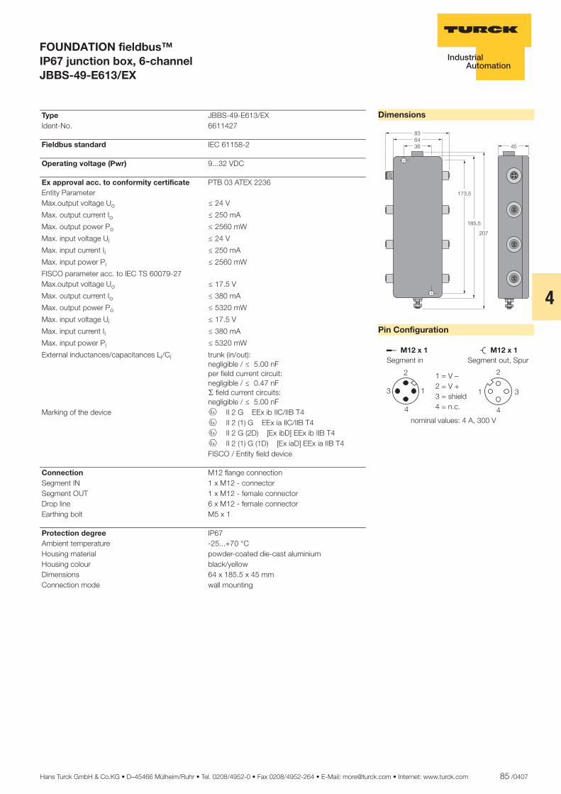
Hans Turck GmbH & Co.KG • D–45466 Mülheim/Ruhr • Tel. 0208/4952-0 • Fax 0208/4952-264 • E-Mail: [email protected] • Internet: www.turck.com 85 /0407
4
ñ Edition:
Hans Turck GmbH & Co.KG ñ D-45472 Mülheim an der Ruhr ñ Witzlebenstraße 7 ñ Tel. 0208 4952-0 ñ Fax 0208 4952-264 ñ [email protected] ñ www.turck.com
FOUNDATION fieldbus™ IP67 junction box, 6-channel JBBS-49-E613/EX
Dimensions
Pin Configuration
������
�����
����
��
�
������� �������
�
� �
�
�
�
�
�
������ ���������������
� ���������������������
�������������������� ������� !
Type JBBS-49-E613/EX Ident-No. 6611427
Fieldbus standard IEC 61158-2
Operating voltage (Pwr) 9...32 VDC
Ex approval acc. to conformity certificate PTB 03 ATEX 2236 Entity Parameter Max.output voltage Uo ð 24 V
Max. output current Io ð 250 mA
Max. output power Po ð 2560 mW
Max. input voltage Ui ð 24 V
Max. input current Ii ð 250 mA
Max. input power Pi ð 2560 mW
FISCO parameter acc. to IEC TS 60079-27 Max.output voltage Uo ð 17.5 V
Max. output current Io ð 380 mA
Max. output power Po ð 5320 mW
Max. input voltage Ui ð 17.5 V
Max. input current Ii ð 380 mA
Max. input power Pi ð 5320 mW
External inductances/capacitances Li/Ci trunk (in/out):negligible / ð 5.00 nFper field current circuit:negligible / ð 0.47 nFæ field current circuits:negligible / ð 5.00 nF
Marking of the device É II 2 G EEx ib IIC/IIB T4 É II 2 (1) G EEx ia IIC/IIB T4 É II 2 G (2D) [Ex ibD] EEx ib IIB T4 É II 2 (1) G (1D) [Ex iaD] EEx ia IIB T4 FISCO / Entity field device
Connection M12 flange connection Segment IN 1 x M12 - connector Segment OUT 1 x M12 - female connector Drop line 6 x M12 - female connector Earthing bolt M5 x 1
Protection degree IP67 Ambient temperature -25...+70 °C Housing material powder-coated die-cast aluminium Housing colour black/yellow Dimensions 64 x 185.5 x 45 mm Connection mode wall mounting
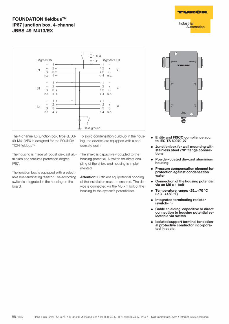
86 /0407 Hans Turck GmbH & Co.KG • D–45466 Mülheim/Ruhr • Tel. 0208/4952-0 • Fax 0208/4952-264 • E-Mail: [email protected] • Internet: www.turck.com
ñ Edition:
Hans Turck GmbH & Co.KG ñ D-45472 Mülheim an der Ruhr ñ Witzlebenstraße 7 ñ Tel. 0208 4952-0 ñ Fax 0208 4952-264 ñ [email protected] ñ www.turck.com
FOUNDATION fieldbus™ IP67 junction box, 4-channel JBBS-49-M413/EX
� Entity and FISCO compliance acc. to IEC TS 60079-27
� Junction box for wall mounting with stainless steel 7/8" flange connec-tions
� Powder-coated die-cast aluminium housing
� Pressure compensation element for protection against condensation water
� Connection of the housing potential via an M5 x 1 bolt
� Temperature range: -25...+70 °C..... (-13...+158 °F)
� Integrated terminating resistor (switch-in)
� Cable shielding: capacitive or direct connection to housing potential se-lectable via switch
� Isolated support terminal for option-al protective conductor incorpora-ted in cable
������
������
�����
�����
��� ��������
��� ���������
��������
The 4-channel Ex junction box, type JBBS-49-M413/EX is designed for the FOUNDA-TION fieldbus™.
The housing is made of robust die-cast alu-minium and features protection degree IP67.
The junction box is equipped with a select-able bus terminating resistor. The according switch is integrated in the housing on the board.
To avoid condensation build-up in the hous-ing, the devices are equipped with a con-densate drain.
The shield is capacitively coupled to the housing potential. A switch for direct cou-pling of the shield and housing is imple-mented.
Attention: Sufficient equipotential bonding of the installation must be ensured. The de-vice is connected via the M5 x 1 bolt of the housing to the system’s potentializer.
����
����
���
����
�� ������
�������
�� ��
����
��
����
��
����
��
����
��
�������
�������
�������
�������
�������
� �� ���� � �� ����
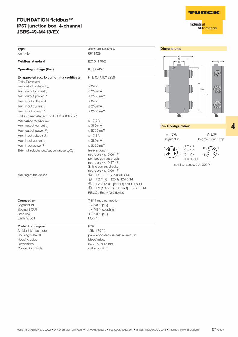
Hans Turck GmbH & Co.KG • D–45466 Mülheim/Ruhr • Tel. 0208/4952-0 • Fax 0208/4952-264 • E-Mail: [email protected] • Internet: www.turck.com 87 /0407
4
ñ Edition:
Hans Turck GmbH & Co.KG ñ D-45472 Mülheim an der Ruhr ñ Witzlebenstraße 7 ñ Tel. 0208 4952-0 ñ Fax 0208 4952-264 ñ [email protected] ñ www.turck.com
FOUNDATION fieldbus™ IP67 junction box, 4-channel JBBS-49-M413/EX
Dimensions
Pin Configuration
��
������
���
��
��
��� ����
�
�
�
�
�
�
�
�
������ ������ ��������
�
�
�
�
�
�
�
�
����������������������
������������ �������!�����"���#
Type JBBS-49-M413/EX Ident-No. 6611429
Fieldbus standard IEC 61158-2
Operating voltage (Pwr) 9...32 VDC
Ex approval acc. to conformity certificate PTB 03 ATEX 2236 Entity Parameter Max.output voltage Uo ð 24 V
Max. output current Io ð 250 mA
Max. output power Po ð 2560 mW
Max. input voltage Ui ð 24 V
Max. input current Ii ð 250 mA
Max. input power Pi ð 2560 mW
FISCO parameter acc. to IEC TS 60079-27 Max.output voltage Uo ð 17.5 V
Max. output current Io ð 380 mA
Max. output power Po ð 5320 mW
Max. input voltage Ui ð 17.5 V
Max. input current Ii ð 380 mA
Max. input power Pi ð 5320 mW
External inductances/capacitances Li/Ci trunk (in/out):negligible / ð 5.00 nFper field current circuit:negligible / ð 0.47 nFæ field current circuits:negligible / ð 5.00 nF
Marking of the device É II 2 G EEx ib IIC/IIB T4 É II 2 (1) G EEx ia IIC/IIB T4 É II 2 G (2D) [Ex ibD] EEx ib IIB T4 É II 2 (1) G (1D) [Ex iaD] EEx ia IIB T4 FISCO / Entity field device
Connection 7/8" flange connection Segment IN 1 x 7/8 "- plug Segment OUT 1 x 7/8 "- coupling Drop line 4 x 7/8 "- plug Earthing bolt M5 x 1
Protection degree IP67 Ambient temperature -25...+70 °C Housing material powder-coated die-cast aluminium Housing colour black/yellow Dimensions 64 x 150 x 45 mm Connection mode wall mounting
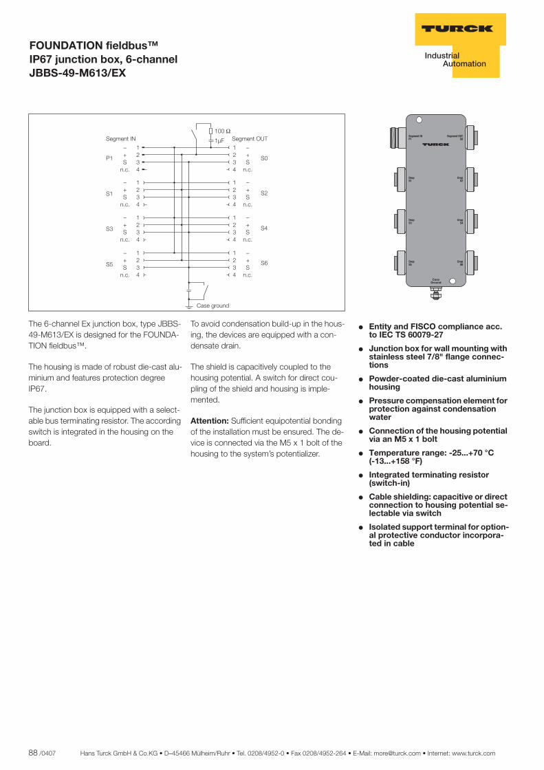
88 /0407 Hans Turck GmbH & Co.KG • D–45466 Mülheim/Ruhr • Tel. 0208/4952-0 • Fax 0208/4952-264 • E-Mail: [email protected] • Internet: www.turck.com
ñ Edition:
Hans Turck GmbH & Co.KG ñ D-45472 Mülheim an der Ruhr ñ Witzlebenstraße 7 ñ Tel. 0208 4952-0 ñ Fax 0208 4952-264 ñ [email protected] ñ www.turck.com
FOUNDATION fieldbus™ IP67 junction box, 6-channel JBBS-49-M613/EX
� Entity and FISCO compliance acc. to IEC TS 60079-27
� Junction box for wall mounting with stainless steel 7/8" flange connec-tions
� Powder-coated die-cast aluminium housing
� Pressure compensation element for protection against condensation water
� Connection of the housing potential via an M5 x 1 bolt
� Temperature range: -25...+70 °C..... (-13...+158 °F)
� Integrated terminating resistor (switch-in)
� Cable shielding: capacitive or direct connection to housing potential se-lectable via switch
� Isolated support terminal for option-al protective conductor incorpora-ted in cable
������
������
�����
�����
��� ��������
��� ���������
����� ��
������
������
The 6-channel Ex junction box, type JBBS-49-M613/EX is designed for the FOUNDA-TION fieldbus™.
The housing is made of robust die-cast alu-minium and features protection degree IP67.
The junction box is equipped with a select-able bus terminating resistor. The according switch is integrated in the housing on the board.
To avoid condensation build-up in the hous-ing, the devices are equipped with a con-densate drain.
The shield is capacitively coupled to the housing potential. A switch for direct cou-pling of the shield and housing is imple-mented.
Attention: Sufficient equipotential bonding of the installation must be ensured. The de-vice is connected via the M5 x 1 bolt of the housing to the system’s potentializer.
����
����
���
����
�� ������
�������
�� ��
����
��
����
��
�������
����
��
����
��
�������
����
��
����
��
�������
�������
�������
�������
�������
� �� ���� � �� �� !"
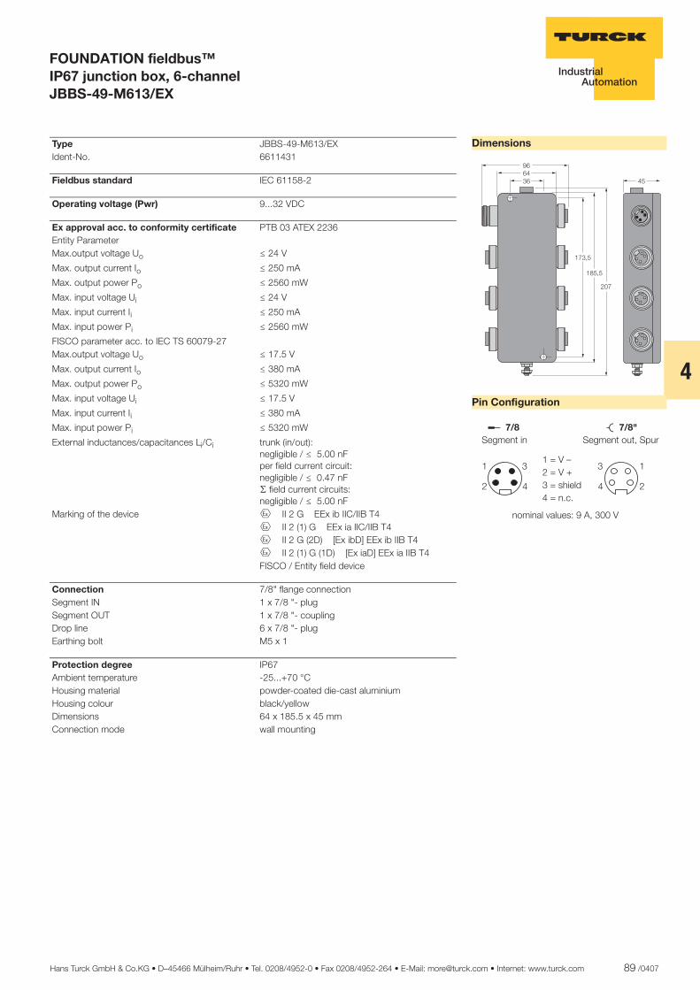
Hans Turck GmbH & Co.KG • D–45466 Mülheim/Ruhr • Tel. 0208/4952-0 • Fax 0208/4952-264 • E-Mail: [email protected] • Internet: www.turck.com 89 /0407
4
ñ Edition:
Hans Turck GmbH & Co.KG ñ D-45472 Mülheim an der Ruhr ñ Witzlebenstraße 7 ñ Tel. 0208 4952-0 ñ Fax 0208 4952-264 ñ [email protected] ñ www.turck.com
FOUNDATION fieldbus™ IP67 junction box, 6-channel JBBS-49-M613/EX
Dimensions
Pin Configuration
������ ��
����
���
��
��� �������������
�
�
�
�
�����������������
�������������������������
��������������������� ����!"!
Type JBBS-49-M613/EX Ident-No. 6611431
Fieldbus standard IEC 61158-2
Operating voltage (Pwr) 9...32 VDC
Ex approval acc. to conformity certificate PTB 03 ATEX 2236 Entity Parameter Max.output voltage Uo ð 24 V
Max. output current Io ð 250 mA
Max. output power Po ð 2560 mW
Max. input voltage Ui ð 24 V
Max. input current Ii ð 250 mA
Max. input power Pi ð 2560 mW
FISCO parameter acc. to IEC TS 60079-27 Max.output voltage Uo ð 17.5 V
Max. output current Io ð 380 mA
Max. output power Po ð 5320 mW
Max. input voltage Ui ð 17.5 V
Max. input current Ii ð 380 mA
Max. input power Pi ð 5320 mW
External inductances/capacitances Li/Ci trunk (in/out):negligible / ð 5.00 nFper field current circuit:negligible / ð 0.47 nFæ field current circuits:negligible / ð 5.00 nF
Marking of the device É II 2 G EEx ib IIC/IIB T4 É II 2 (1) G EEx ia IIC/IIB T4 É II 2 G (2D) [Ex ibD] EEx ib IIB T4 É II 2 (1) G (1D) [Ex iaD] EEx ia IIB T4 FISCO / Entity field device
Connection 7/8" flange connection Segment IN 1 x 7/8 "- plug Segment OUT 1 x 7/8 "- coupling Drop line 6 x 7/8 "- plug Earthing bolt M5 x 1
Protection degree IP67 Ambient temperature -25...+70 °C Housing material powder-coated die-cast aluminium Housing colour black/yellow Dimensions 64 x 185.5 x 45 mm Connection mode wall mounting
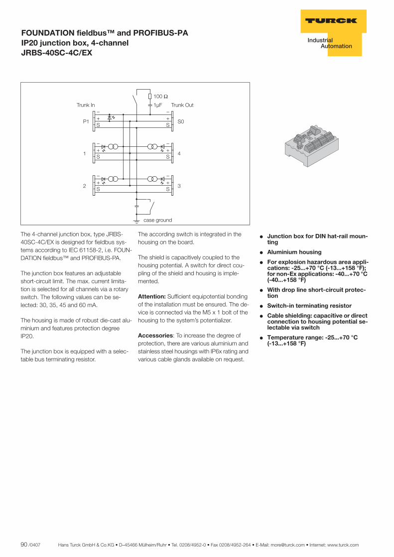
90 /0407 Hans Turck GmbH & Co.KG • D–45466 Mülheim/Ruhr • Tel. 0208/4952-0 • Fax 0208/4952-264 • E-Mail: [email protected] • Internet: www.turck.com
ñ Edition:
Hans Turck GmbH & Co.KG ñ D-45472 Mülheim an der Ruhr ñ Witzlebenstraße 7 ñ Tel. 0208 4952-0 ñ Fax 0208 4952-264 ñ [email protected] ñ www.turck.com
FOUNDATION fieldbus™ and PROFIBUS-PA IP20 junction box, 4-channel JRBS-40SC-4C/EX
� Junction box for DIN hat-rail moun-ting
� Aluminium housing
� For explosion hazardous area appli-cations: -25...+70 °C (-13...+158 °F); for non-Ex applications: -40...+70 °C (-40...+158 °F)
� With drop line short-circuit protec-tion
� Switch-in terminating resistor
� Cable shielding: capacitive or direct connection to housing potential se-lectable via switch
� Temperature range: -25...+70 °C..... (-13...+158 °F)
The 4-channel junction box, type JRBS-40SC-4C/EX is designed for fieldbus sys-tems according to IEC 61158-2, i.e. FOUN-DATION fieldbus™ and PROFIBUS-PA.
The junction box features an adjustable short-circuit limit. The max. current limita-tion is selected for all channels via a rotary switch. The following values can be se-lected: 30, 35, 45 and 60 mA.
The housing is made of robust die-cast alu-minium and features protection degree IP20.
The junction box is equipped with a selec-table bus terminating resistor.
The according switch is integrated in the housing on the board.
The shield is capacitively coupled to the housing potential. A switch for direct cou-pling of the shield and housing is imple-mented.
Attention: Sufficient equipotential bonding of the installation must be ensured. The de-vice is connected via the M5 x 1 bolt of the housing to the system’s potentializer.
Accessories: To increase the degree of protection, there are various aluminium and stainless steel housings with IP6x rating and various cable glands available on request.
���
����
�� ��
� �
���
���
���
���
���!�� ���!���
� �
���
���
��� ������
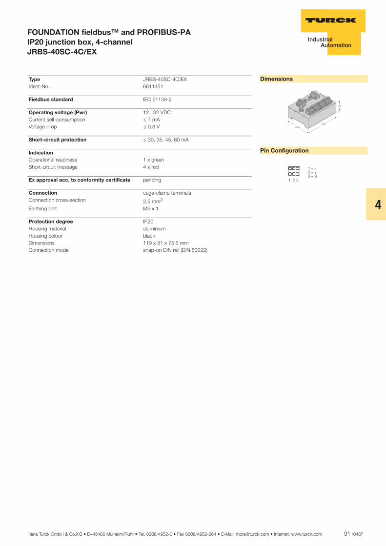
Hans Turck GmbH & Co.KG • D–45466 Mülheim/Ruhr • Tel. 0208/4952-0 • Fax 0208/4952-264 • E-Mail: [email protected] • Internet: www.turck.com 91 /0407
4
ñ Edition:
Hans Turck GmbH & Co.KG ñ D-45472 Mülheim an der Ruhr ñ Witzlebenstraße 7 ñ Tel. 0208 4952-0 ñ Fax 0208 4952-264 ñ [email protected] ñ www.turck.com
FOUNDATION fieldbus™ and PROFIBUS-PA IP20 junction box, 4-channel JRBS-40SC-4C/EX
Dimensions
Pin Configuration
�������
��
� � �
��������������
Type JRBS-40SC-4C/EX Ident-No. 6611451
Fieldbus standard IEC 61158-2
Operating voltage (Pwr) 12...32 VDC Current self-consumption ð 7 mA Voltage drop ð 0.3 V
Short-circuit protection ð 30, 35, 45, 60 mA
Indication Operational readiness 1 x green Short-circuit message 4 x red
Ex approval acc. to conformity certificate pending
Connection cage-clamp terminals Connection cross-section 2.5 mm2
Earthing bolt M5 x 1
Protection degree IP20 Housing material aluminium Housing colour black Dimensions 119 x 31 x 75.5 mm Connection mode snap-on DIN rail (DIN 50022)
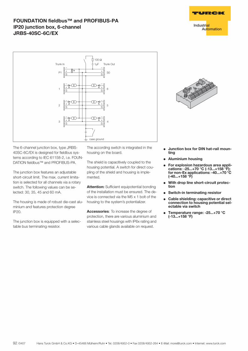
92 /0407 Hans Turck GmbH & Co.KG • D–45466 Mülheim/Ruhr • Tel. 0208/4952-0 • Fax 0208/4952-264 • E-Mail: [email protected] • Internet: www.turck.com
ñ Edition:
Hans Turck GmbH & Co.KG ñ D-45472 Mülheim an der Ruhr ñ Witzlebenstraße 7 ñ Tel. 0208 4952-0 ñ Fax 0208 4952-264 ñ [email protected] ñ www.turck.com
FOUNDATION fieldbus™ and PROFIBUS-PA IP20 junction box, 6-channel JRBS-40SC-6C/EX
� Junction box for DIN hat-rail moun-ting
� Aluminium housing
� For explosion hazardous area appli-cations: -25...+70 °C (-13...+158 °F); for non-Ex applications: -40...+70 °C (-40...+158 °F)
� With drop line short-circuit protec-tion
� Switch-in terminating resistor
� Cable shielding: capacitive or direct connection to housing potential sel-ectable via switch
� Temperature range: -25...+70 °C..... (-13...+158 °F)
The 6-channel junction box, type JRBS-40SC-6C/EX is designed for fieldbus sys-tems according to IEC 61158-2, i.e. FOUN-DATION fieldbus™ and PROFIBUS-PA.
The junction box features an adjustable short-circuit limit. The max. current limita-tion is selected for all channels via a rotary switch. The following values can be se-lected: 30, 35, 45 and 60 mA.
The housing is made of robust die-cast alu-minium and features protection degree IP20.
The junction box is equipped with a selec-table bus terminating resistor.
The according switch is integrated in the housing on the board.
The shield is capacitively coupled to the housing potential. A switch for direct cou-pling of the shield and housing is imple-mented.
Attention: Sufficient equipotential bonding of the installation must be ensured. The de-vice is connected via the M5 x 1 bolt of the housing to the system’s potentializer.
Accessories: To increase the degree of protection, there are various aluminium and stainless steel housings with IP6x rating and various cable glands available on request.
���
�����
�� ��
�
�
�
�
���
���
���
���
���
���
�������� ���������
� �
���
���
�� !�"�#��$
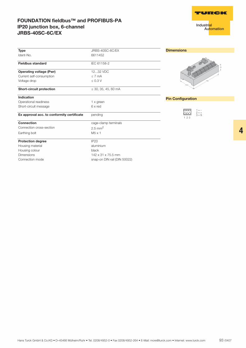
Hans Turck GmbH & Co.KG • D–45466 Mülheim/Ruhr • Tel. 0208/4952-0 • Fax 0208/4952-264 • E-Mail: [email protected] • Internet: www.turck.com 93 /0407
4
ñ Edition:
Hans Turck GmbH & Co.KG ñ D-45472 Mülheim an der Ruhr ñ Witzlebenstraße 7 ñ Tel. 0208 4952-0 ñ Fax 0208 4952-264 ñ [email protected] ñ www.turck.com
FOUNDATION fieldbus™ and PROFIBUS-PA IP20 junction box, 6-channel JRBS-40SC-6C/EX
Dimensions
Pin Configuration
���
����
��
� � �
������������
Type JRBS-40SC-6C/EX Ident-No. 6611452
Fieldbus standard IEC 61158-2
Operating voltage (Pwr) 12...32 VDC Current self-consumption ð 7 mA Voltage drop ð 0.3 V
Short-circuit protection ð 30, 35, 45, 60 mA
Indication Operational readiness 1 x green Short-circuit message 6 x red
Ex approval acc. to conformity certificate pending
Connection cage-clamp terminals Connection cross-section 2.5 mm2
Earthing bolt M5 x 1
Protection degree IP20 Housing material aluminium Housing colour black Dimensions 142 x 31 x 75.5 mm Connection mode snap-on DIN rail (DIN 50022)
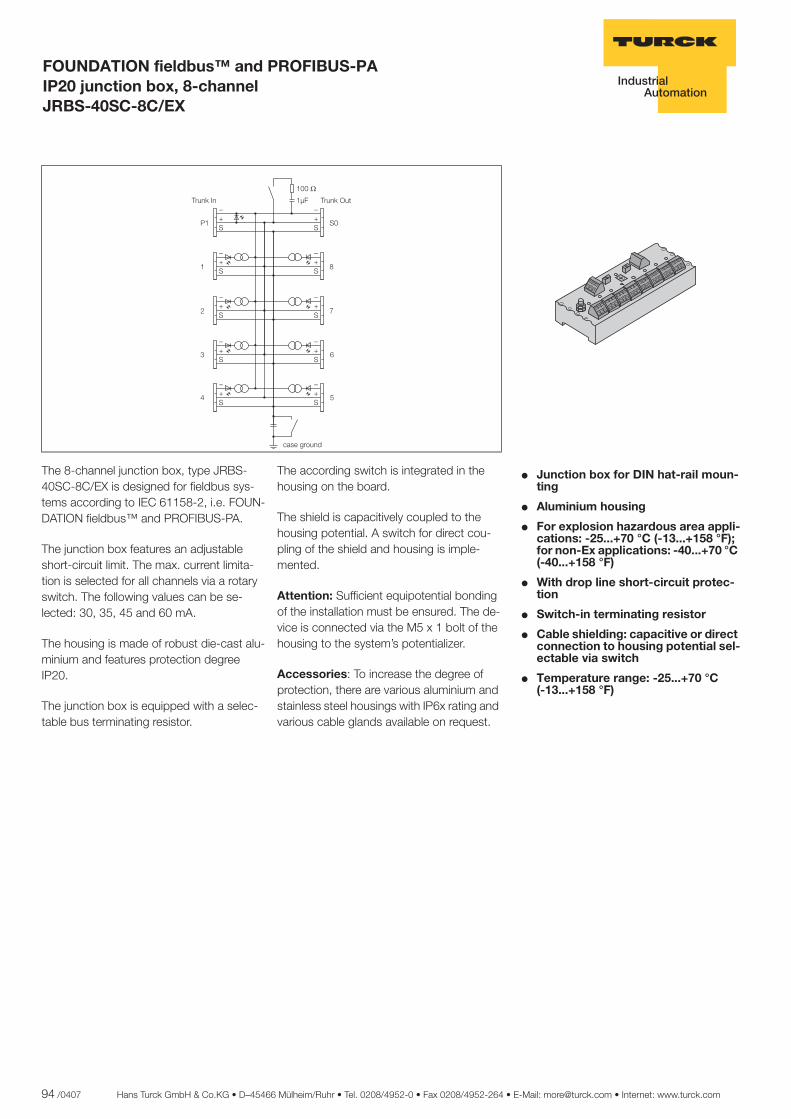
94 /0407 Hans Turck GmbH & Co.KG • D–45466 Mülheim/Ruhr • Tel. 0208/4952-0 • Fax 0208/4952-264 • E-Mail: [email protected] • Internet: www.turck.com
ñ Edition:
Hans Turck GmbH & Co.KG ñ D-45472 Mülheim an der Ruhr ñ Witzlebenstraße 7 ñ Tel. 0208 4952-0 ñ Fax 0208 4952-264 ñ [email protected] ñ www.turck.com
FOUNDATION fieldbus™ and PROFIBUS-PA IP20 junction box, 8-channel JRBS-40SC-8C/EX
� Junction box for DIN hat-rail moun-ting
� Aluminium housing
� For explosion hazardous area appli-cations: -25...+70 °C (-13...+158 °F); for non-Ex applications: -40...+70 °C (-40...+158 °F)
� With drop line short-circuit protec-tion
� Switch-in terminating resistor
� Cable shielding: capacitive or direct connection to housing potential sel-ectable via switch
� Temperature range: -25...+70 °C..... (-13...+158 °F)
The 8-channel junction box, type JRBS-40SC-8C/EX is designed for fieldbus sys-tems according to IEC 61158-2, i.e. FOUN-DATION fieldbus™ and PROFIBUS-PA.
The junction box features an adjustable short-circuit limit. The max. current limita-tion is selected for all channels via a rotary switch. The following values can be se-lected: 30, 35, 45 and 60 mA.
The housing is made of robust die-cast alu-minium and features protection degree IP20.
The junction box is equipped with a selec-table bus terminating resistor.
The according switch is integrated in the housing on the board.
The shield is capacitively coupled to the housing potential. A switch for direct cou-pling of the shield and housing is imple-mented.
Attention: Sufficient equipotential bonding of the installation must be ensured. The de-vice is connected via the M5 x 1 bolt of the housing to the system’s potentializer.
Accessories: To increase the degree of protection, there are various aluminium and stainless steel housings with IP6x rating and various cable glands available on request.
���
�����
�� ��
�
�
� �
� �
� �
� �
� �
� �
�������� ���������
� �
� �
� �
�����������
�
� �
� �
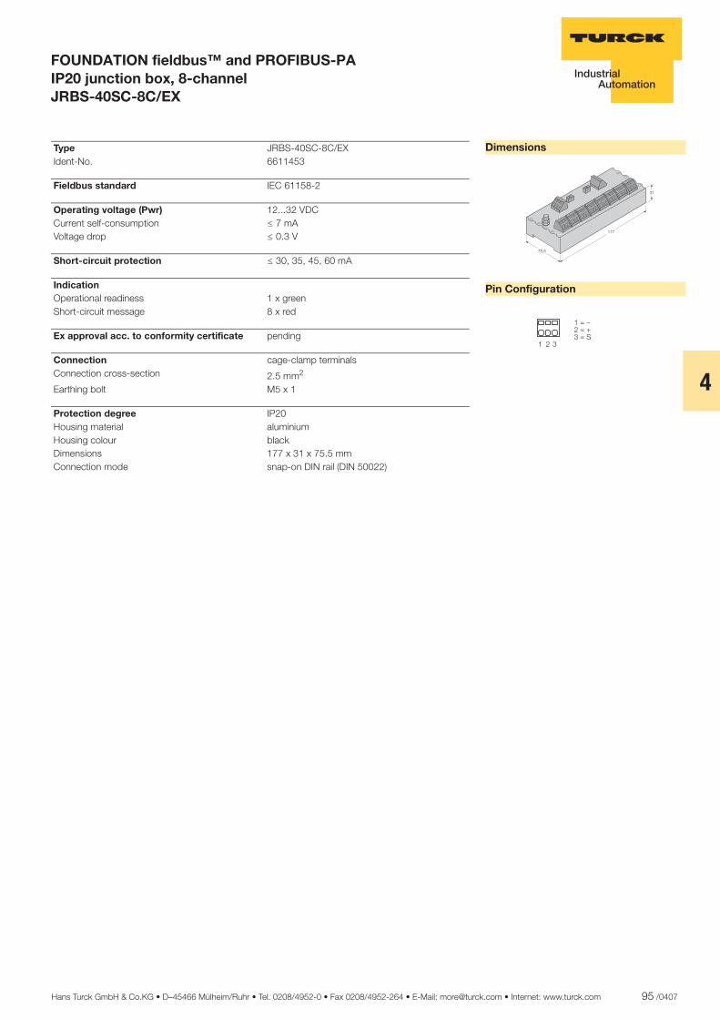
Hans Turck GmbH & Co.KG • D–45466 Mülheim/Ruhr • Tel. 0208/4952-0 • Fax 0208/4952-264 • E-Mail: [email protected] • Internet: www.turck.com 95 /0407
4
ñ Edition:
Hans Turck GmbH & Co.KG ñ D-45472 Mülheim an der Ruhr ñ Witzlebenstraße 7 ñ Tel. 0208 4952-0 ñ Fax 0208 4952-264 ñ [email protected] ñ www.turck.com
FOUNDATION fieldbus™ and PROFIBUS-PA IP20 junction box, 8-channel JRBS-40SC-8C/EX
Dimensions
Pin Configuration
���
����
��
� � �
��������������
Type JRBS-40SC-8C/EX Ident-No. 6611453
Fieldbus standard IEC 61158-2
Operating voltage (Pwr) 12...32 VDC Current self-consumption ð 7 mA Voltage drop ð 0.3 V
Short-circuit protection ð 30, 35, 45, 60 mA
Indication Operational readiness 1 x green Short-circuit message 8 x red
Ex approval acc. to conformity certificate pending
Connection cage-clamp terminals Connection cross-section 2.5 mm2
Earthing bolt M5 x 1
Protection degree IP20 Housing material aluminium Housing colour black Dimensions 177 x 31 x 75.5 mm Connection mode snap-on DIN rail (DIN 50022)

96 /0407 Hans Turck GmbH & Co.KG • D–45466 Mülheim/Ruhr • Tel. 0208/4952-0 • Fax 0208/4952-264 • E-Mail: [email protected] • Internet: www.turck.com
ñ Edition:
Hans Turck GmbH & Co.KG ñ D-45472 Mülheim an der Ruhr ñ Witzlebenstraße 7 ñ Tel. 0208 4952-0 ñ Fax 0208 4952-264 ñ [email protected] ñ www.turck.com
FOUNDATION fieldbus™ and PROFIBUS-PA IP20 junction module, 12-channel JRBS-40SC-12C/EX
� Junction box for DIN hat-rail moun-ting
� Aluminium housing
� For explosion hazardous area appli-cations: -25...+70 °C (-13...+158 °F); for non-Ex applications: -40...+70 °C (-40...+158 °F)
� With drop line short-circuit protec-tion
� Switch-in terminating resistor
� Cable shielding: capacitive or direct connection to housing potential sel-ectable via switch
� Temperature range: -25...+70 °C..... (-13...+158 °F)
The 12-channel junction box, type JRBS-40SC-12C/EX is designed for fieldbus sys-tems according to IEC 61158-2, i.e. FOUN-DATION fieldbus™ and PROFIBUS-PA.
The junction box features an adjustable short-circuit limit. The max. current limita-tion is selected for all channels via a rotary switch. The following values can be se-lected: 30, 35, 45 and 60 mA.
The housing is made of robust die-cast alu-minium and features protection degree IP20.
The junction box is equipped with a selec-table bus terminating resistor.
The according switch is integrated in the housing on the board.
The shield is capacitively coupled to the housing potential. A switch for direct cou-pling of the shield and housing is imple-mented.
Attention: Sufficient equipotential bonding of the installation must be ensured. The de-vice is connected via the M5 x 1 bolt of the housing to the system’s potentializer.
Accessories: To increase the degree of protection, there are various aluminium and stainless steel housings with IP6x rating and various cable glands available on request.
���
�����
�� ��
�
�
�
� �
� �
� �
� �
� �
� �
�������� ���������
�����������
���
���
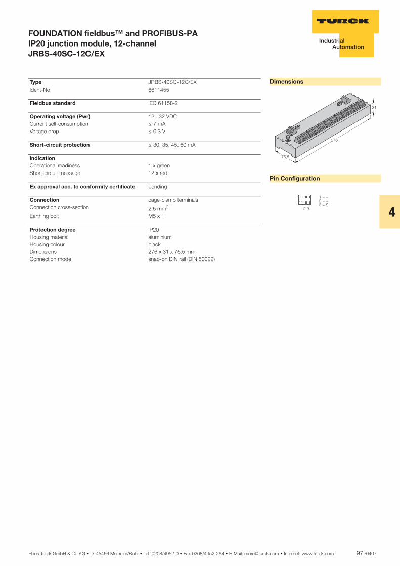
Hans Turck GmbH & Co.KG • D–45466 Mülheim/Ruhr • Tel. 0208/4952-0 • Fax 0208/4952-264 • E-Mail: [email protected] • Internet: www.turck.com 97 /0407
4
ñ Edition:
Hans Turck GmbH & Co.KG ñ D-45472 Mülheim an der Ruhr ñ Witzlebenstraße 7 ñ Tel. 0208 4952-0 ñ Fax 0208 4952-264 ñ [email protected] ñ www.turck.com
FOUNDATION fieldbus™ and PROFIBUS-PA IP20 junction module, 12-channel JRBS-40SC-12C/EX
Dimensions
Pin Configuration
���
����
��
� � �
��������������
Type JRBS-40SC-12C/EX Ident-No. 6611455
Fieldbus standard IEC 61158-2
Operating voltage (Pwr) 12...32 VDC Current self-consumption ð 7 mA Voltage drop ð 0.3 V
Short-circuit protection ð 30, 35, 45, 60 mA
Indication Operational readiness 1 x green Short-circuit message 12 x red
Ex approval acc. to conformity certificate pending
Connection cage-clamp terminals Connection cross-section 2.5 mm2
Earthing bolt M5 x 1
Protection degree IP20 Housing material aluminium Housing colour black Dimensions 276 x 31 x 75.5 mm Connection mode snap-on DIN rail (DIN 50022)
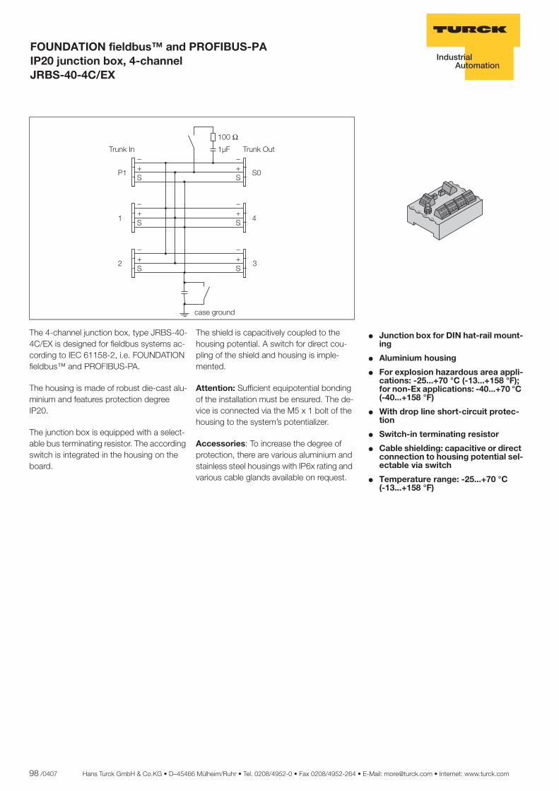
98 /0407 Hans Turck GmbH & Co.KG • D–45466 Mülheim/Ruhr • Tel. 0208/4952-0 • Fax 0208/4952-264 • E-Mail: [email protected] • Internet: www.turck.com
ñ Edition:
Hans Turck GmbH & Co.KG ñ D-45472 Mülheim an der Ruhr ñ Witzlebenstraße 7 ñ Tel. 0208 4952-0 ñ Fax 0208 4952-264 ñ [email protected] ñ www.turck.com
FOUNDATION fieldbus™ and PROFIBUS-PA IP20 junction box, 4-channel JRBS-40-4C/EX
� Junction box for DIN hat-rail mount-ing
� Aluminium housing
� For explosion hazardous area appli-cations: -25...+70 °C (-13...+158 °F); for non-Ex applications: -40...+70 °C (-40...+158 °F)
� With drop line short-circuit protec-tion
� Switch-in terminating resistor
� Cable shielding: capacitive or direct connection to housing potential sel-ectable via switch
� Temperature range: -25...+70 °C..... (-13...+158 °F)
The 4-channel junction box, type JRBS-40-4C/EX is designed for fieldbus systems ac-cording to IEC 61158-2, i.e. FOUNDATION fieldbus™ and PROFIBUS-PA.
The housing is made of robust die-cast alu-minium and features protection degree IP20.
The junction box is equipped with a select-able bus terminating resistor. The according switch is integrated in the housing on the board.
The shield is capacitively coupled to the housing potential. A switch for direct cou-pling of the shield and housing is imple-mented.
Attention: Sufficient equipotential bonding of the installation must be ensured. The de-vice is connected via the M5 x 1 bolt of the housing to the system’s potentializer.
Accessories: To increase the degree of protection, there are various aluminium and stainless steel housings with IP6x rating and various cable glands available on request.
���
����
�� ��
�
�
�
�
���
���
���
���
���
���
���!�� ���!���
��� ������
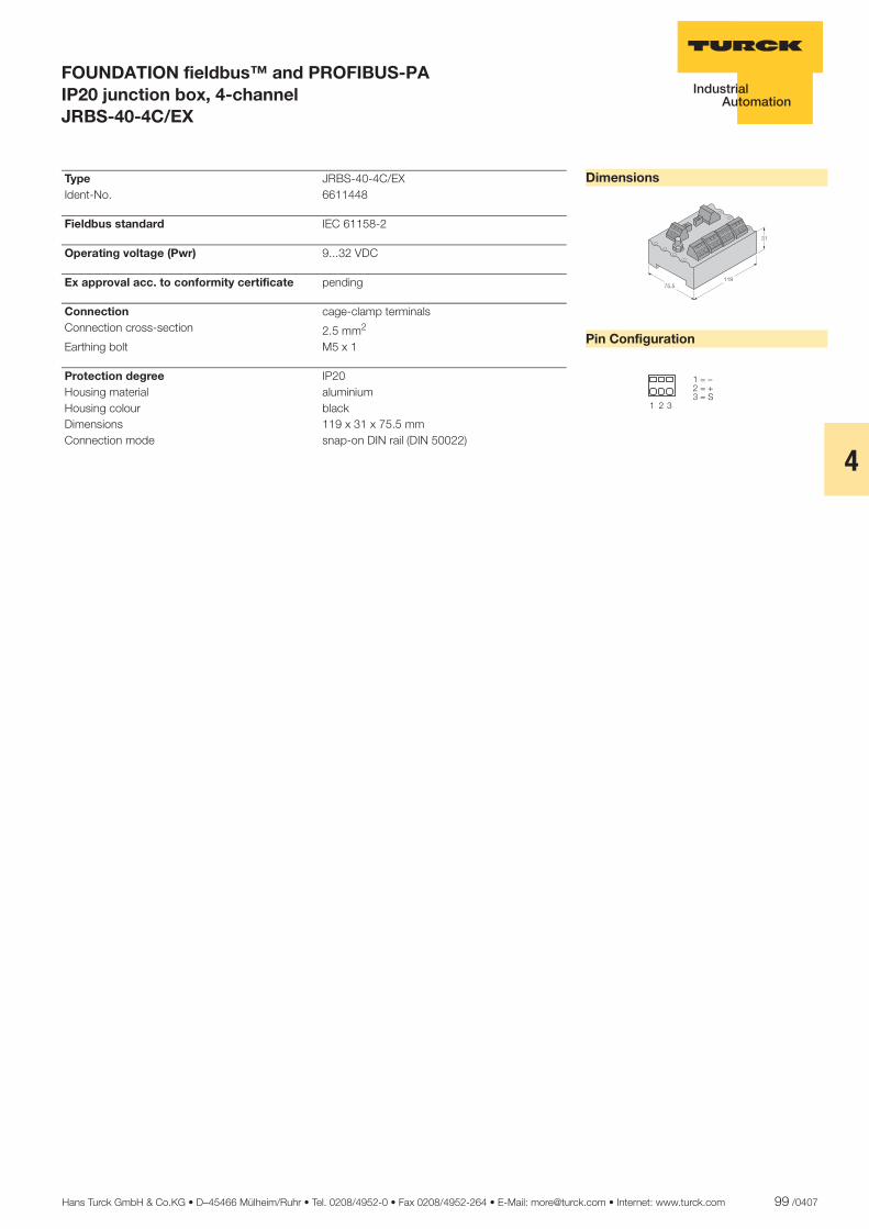
Hans Turck GmbH & Co.KG • D–45466 Mülheim/Ruhr • Tel. 0208/4952-0 • Fax 0208/4952-264 • E-Mail: [email protected] • Internet: www.turck.com 99 /0407
4
ñ Edition:
Hans Turck GmbH & Co.KG ñ D-45472 Mülheim an der Ruhr ñ Witzlebenstraße 7 ñ Tel. 0208 4952-0 ñ Fax 0208 4952-264 ñ [email protected] ñ www.turck.com
FOUNDATION fieldbus™ and PROFIBUS-PA IP20 junction box, 4-channel JRBS-40-4C/EX
Dimensions
Pin Configuration
�������
��
� � �
��������������
Type JRBS-40-4C/EX Ident-No. 6611448
Fieldbus standard IEC 61158-2
Operating voltage (Pwr) 9...32 VDC
Ex approval acc. to conformity certificate pending
Connection cage-clamp terminals Connection cross-section 2.5 mm2
Earthing bolt M5 x 1
Protection degree IP20 Housing material aluminium Housing colour black Dimensions 119 x 31 x 75.5 mm Connection mode snap-on DIN rail (DIN 50022)
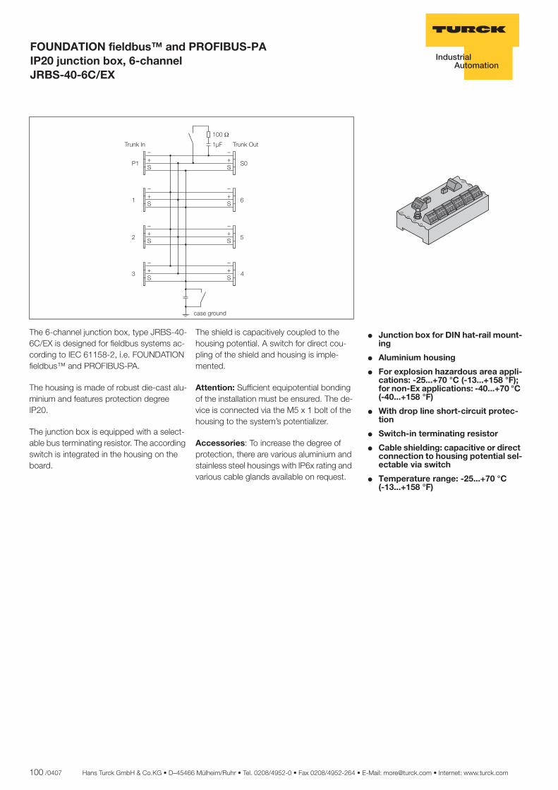
100 /0407 Hans Turck GmbH & Co.KG • D–45466 Mülheim/Ruhr • Tel. 0208/4952-0 • Fax 0208/4952-264 • E-Mail: [email protected] • Internet: www.turck.com
ñ Edition:
Hans Turck GmbH & Co.KG ñ D-45472 Mülheim an der Ruhr ñ Witzlebenstraße 7 ñ Tel. 0208 4952-0 ñ Fax 0208 4952-264 ñ [email protected] ñ www.turck.com
FOUNDATION fieldbus™ and PROFIBUS-PA IP20 junction box, 6-channel JRBS-40-6C/EX
� Junction box for DIN hat-rail mount-ing
� Aluminium housing
� For explosion hazardous area appli-cations: -25...+70 °C (-13...+158 °F); for non-Ex applications: -40...+70 °C (-40...+158 °F)
� With drop line short-circuit protec-tion
� Switch-in terminating resistor
� Cable shielding: capacitive or direct connection to housing potential sel-ectable via switch
� Temperature range: -25...+70 °C..... (-13...+158 °F)
The 6-channel junction box, type JRBS-40-6C/EX is designed for fieldbus systems ac-cording to IEC 61158-2, i.e. FOUNDATION fieldbus™ and PROFIBUS-PA.
The housing is made of robust die-cast alu-minium and features protection degree IP20.
The junction box is equipped with a select-able bus terminating resistor. The according switch is integrated in the housing on the board.
The shield is capacitively coupled to the housing potential. A switch for direct cou-pling of the shield and housing is imple-mented.
Attention: Sufficient equipotential bonding of the installation must be ensured. The de-vice is connected via the M5 x 1 bolt of the housing to the system’s potentializer.
Accessories: To increase the degree of protection, there are various aluminium and stainless steel housings with IP6x rating and various cable glands available on request.
���
�����
�� ��
�
�
� �
� �
� �
� �
� �
� �
�������� ���������
� �
� �
� �
�����������
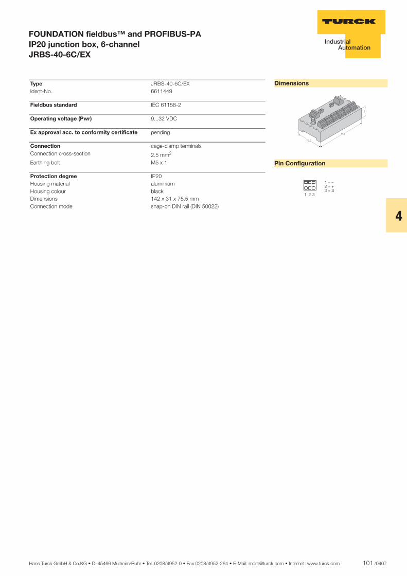
Hans Turck GmbH & Co.KG • D–45466 Mülheim/Ruhr • Tel. 0208/4952-0 • Fax 0208/4952-264 • E-Mail: [email protected] • Internet: www.turck.com 101 /0407
4
ñ Edition:
Hans Turck GmbH & Co.KG ñ D-45472 Mülheim an der Ruhr ñ Witzlebenstraße 7 ñ Tel. 0208 4952-0 ñ Fax 0208 4952-264 ñ [email protected] ñ www.turck.com
FOUNDATION fieldbus™ and PROFIBUS-PA IP20 junction box, 6-channel JRBS-40-6C/EX
Dimensions
Pin Configuration
���
����
��
� � �
��������������
Type JRBS-40-6C/EX Ident-No. 6611449
Fieldbus standard IEC 61158-2
Operating voltage (Pwr) 9...32 VDC
Ex approval acc. to conformity certificate pending
Connection cage-clamp terminals Connection cross-section 2.5 mm2
Earthing bolt M5 x 1
Protection degree IP20 Housing material aluminium Housing colour black Dimensions 142 x 31 x 75.5 mm Connection mode snap-on DIN rail (DIN 50022)

102 /0407 Hans Turck GmbH & Co.KG • D–45466 Mülheim/Ruhr • Tel. 0208/4952-0 • Fax 0208/4952-264 • E-Mail: [email protected] • Internet: www.turck.com
ñ Edition:
Hans Turck GmbH & Co.KG ñ D-45472 Mülheim an der Ruhr ñ Witzlebenstraße 7 ñ Tel. 0208 4952-0 ñ Fax 0208 4952-264 ñ [email protected] ñ www.turck.com
FOUNDATION fieldbus™ and PROFIBUS-PA IP20 junction box, 8-channel JRBS-40-8C/EX
� Junction box for DIN hat-rail mount-ing
� Aluminium housing
� For explosion hazardous area appli-cations: -25...+70 °C (-13...+158 °F); for non-Ex applications: -40...+70 °C (-40...+158 °F)
� With drop line short-circuit protec-tion
� Switch-in terminating resistor
� Cable shielding: capacitive or direct connection to housing potential sel-ectable via switch
� Temperature range: -25...+70 °C..... (-13...+158 °F)
The 8-channel junction box, type JRBS-40-8C/EX is designed for fieldbus systems ac-cording to IEC 61158-2, i.e. FOUNDATION fieldbus™ and PROFIBUS-PA.
The housing is made of robust die-cast alu-minium and features protection degree IP20.
The junction box is equipped with a select-able bus terminating resistor. The according switch is integrated in the housing on the board.
The shield is capacitively coupled to the housing potential. A switch for direct cou-pling of the shield and housing is imple-mented.
Attention: Sufficient equipotential bonding of the installation must be ensured. The de-vice is connected via the M5 x 1 bolt of the housing to the system’s potentializer.
Accessories: To increase the degree of protection, there are various aluminium and stainless steel housings with IP6x rating and various cable glands available on request.
���
�����
�� ��
�
�
� �
� �
� �
� �
� �
� �
�������� ���������
� �
� �
� �
� �
� �
� �
����������
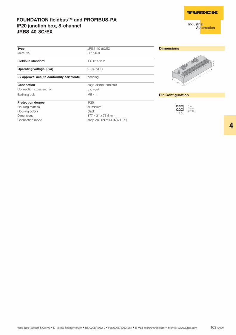
Hans Turck GmbH & Co.KG • D–45466 Mülheim/Ruhr • Tel. 0208/4952-0 • Fax 0208/4952-264 • E-Mail: [email protected] • Internet: www.turck.com 103 /0407
4
ñ Edition:
Hans Turck GmbH & Co.KG ñ D-45472 Mülheim an der Ruhr ñ Witzlebenstraße 7 ñ Tel. 0208 4952-0 ñ Fax 0208 4952-264 ñ [email protected] ñ www.turck.com
FOUNDATION fieldbus™ and PROFIBUS-PA IP20 junction box, 8-channel JRBS-40-8C/EX
Dimensions
Pin Configuration
���
����
��
� �
���� ���������
Type JRBS-40-8C/EX Ident-No. 6611450
Fieldbus standard IEC 61158-2
Operating voltage (Pwr) 9...32 VDC
Ex approval acc. to conformity certificate pending
Connection cage-clamp terminals Connection cross-section 2.5 mm2
Earthing bolt M5 x 1
Protection degree IP20 Housing material aluminium Housing colour black Dimensions 177 x 31 x 75.5 mm Connection mode snap-on DIN rail (DIN 50022)
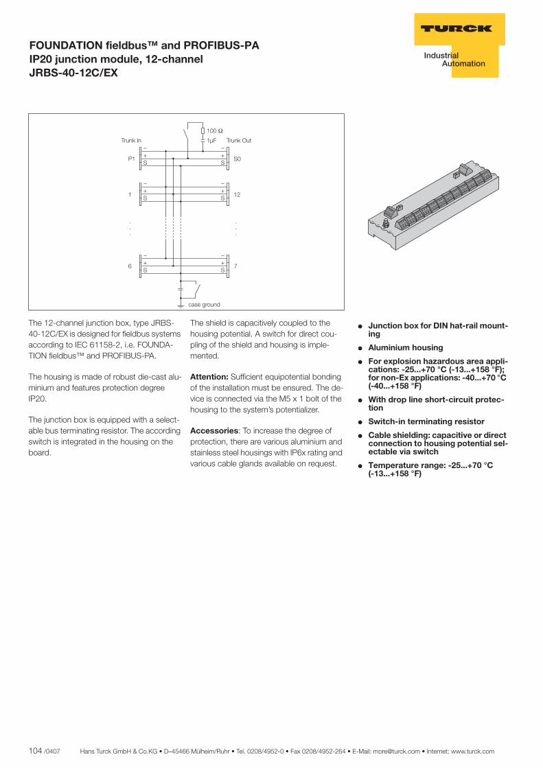
104 /0407 Hans Turck GmbH & Co.KG • D–45466 Mülheim/Ruhr • Tel. 0208/4952-0 • Fax 0208/4952-264 • E-Mail: [email protected] • Internet: www.turck.com
ñ Edition:
Hans Turck GmbH & Co.KG ñ D-45472 Mülheim an der Ruhr ñ Witzlebenstraße 7 ñ Tel. 0208 4952-0 ñ Fax 0208 4952-264 ñ [email protected] ñ www.turck.com
FOUNDATION fieldbus™ and PROFIBUS-PA IP20 junction module, 12-channel JRBS-40-12C/EX
� Junction box for DIN hat-rail mount-ing
� Aluminium housing
� For explosion hazardous area appli-cations: -25...+70 °C (-13...+158 °F); for non-Ex applications: -40...+70 °C (-40...+158 °F)
� With drop line short-circuit protec-tion
� Switch-in terminating resistor
� Cable shielding: capacitive or direct connection to housing potential sel-ectable via switch
� Temperature range: -25...+70 °C..... (-13...+158 °F)
The 12-channel junction box, type JRBS-40-12C/EX is designed for fieldbus systems according to IEC 61158-2, i.e. FOUNDA-TION fieldbus™ and PROFIBUS-PA.
The housing is made of robust die-cast alu-minium and features protection degree IP20.
The junction box is equipped with a select-able bus terminating resistor. The according switch is integrated in the housing on the board.
The shield is capacitively coupled to the housing potential. A switch for direct cou-pling of the shield and housing is imple-mented.
Attention: Sufficient equipotential bonding of the installation must be ensured. The de-vice is connected via the M5 x 1 bolt of the housing to the system’s potentializer.
Accessories: To increase the degree of protection, there are various aluminium and stainless steel housings with IP6x rating and various cable glands available on request.
���
�����
�� ��
� �
��
��
��
��
� ������ � �������
� �
��
��
������ ����
���
���
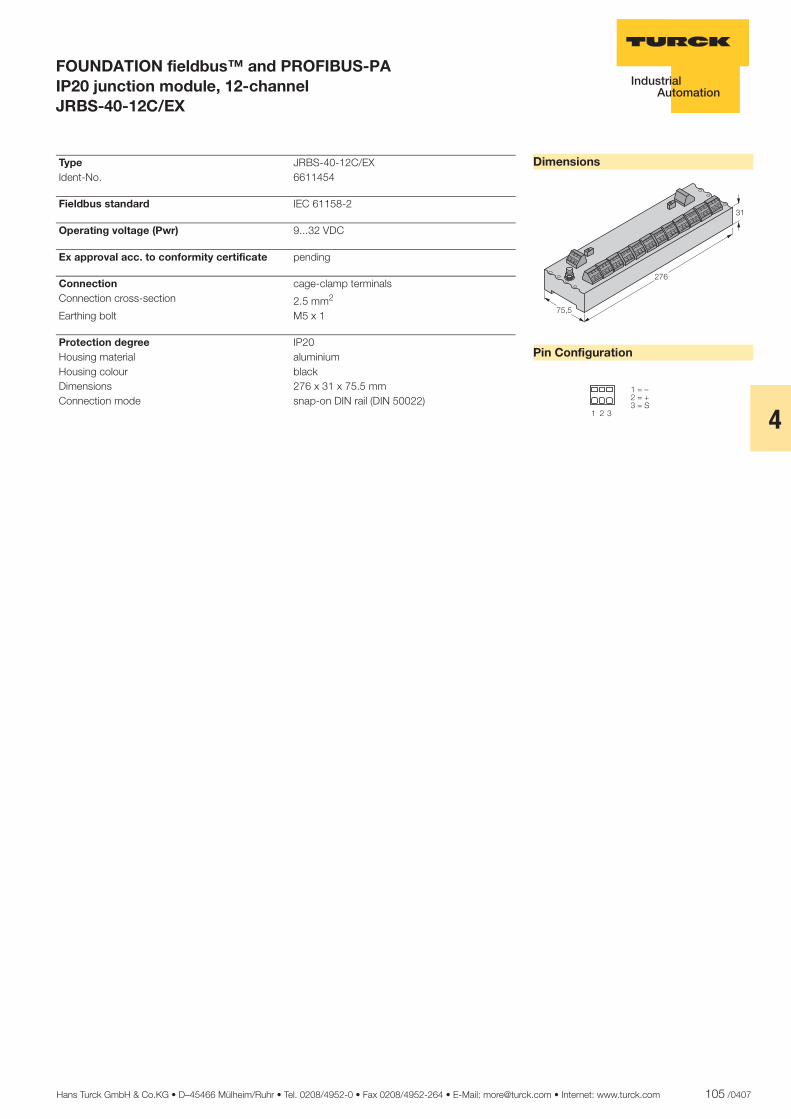
Hans Turck GmbH & Co.KG • D–45466 Mülheim/Ruhr • Tel. 0208/4952-0 • Fax 0208/4952-264 • E-Mail: [email protected] • Internet: www.turck.com 105 /0407
4
ñ Edition:
Hans Turck GmbH & Co.KG ñ D-45472 Mülheim an der Ruhr ñ Witzlebenstraße 7 ñ Tel. 0208 4952-0 ñ Fax 0208 4952-264 ñ [email protected] ñ www.turck.com
FOUNDATION fieldbus™ and PROFIBUS-PA IP20 junction module, 12-channel JRBS-40-12C/EX
Dimensions
Pin Configuration
���
����
��
� � �
��������������
Type JRBS-40-12C/EX Ident-No. 6611454
Fieldbus standard IEC 61158-2
Operating voltage (Pwr) 9...32 VDC
Ex approval acc. to conformity certificate pending
Connection cage-clamp terminals Connection cross-section 2.5 mm2
Earthing bolt M5 x 1
Protection degree IP20 Housing material aluminium Housing colour black Dimensions 276 x 31 x 75.5 mm Connection mode snap-on DIN rail (DIN 50022)
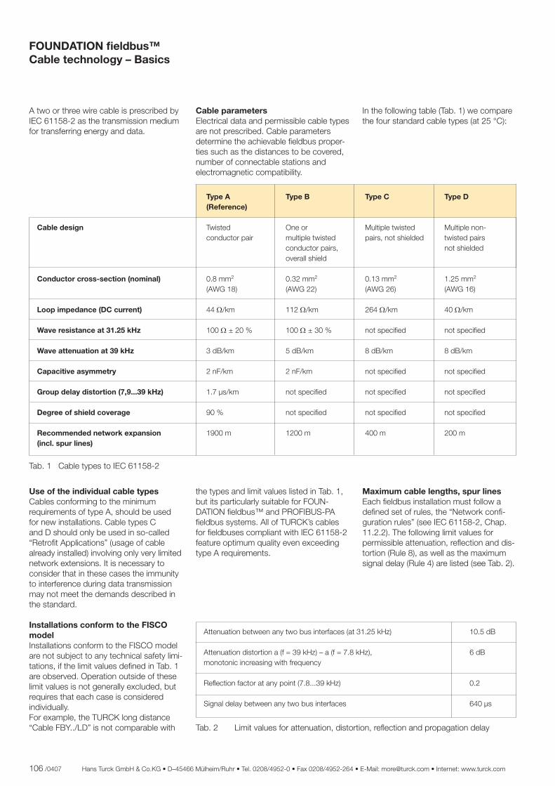
106 /0407 Hans Turck GmbH & Co.KG • D–45466 Mülheim/Ruhr • Tel. 0208/4952-0 • Fax 0208/4952-264 • E-Mail: [email protected] • Internet: www.turck.com
A two or three wire cable is prescribed by IEC 61158-2 as the transmission medium for transferring energy and data.
Cable parametersElectrical data and permissible cable types are not prescribed. Cable parameters determine the achievable fi eldbus proper-ties such as the distances to be covered, number of connectable stations and electromagnetic compatibility.
In the following table (Tab. 1) we compare the four standard cable types (at 25 °C):
Type A Type B Type C Type D (Reference)
Cable design Twisted One or Multiple twisted Multiple non- conductor pair multiple twisted pairs, not shielded twisted pairs conductor pairs, not shielded overall shield
Conductor cross-section (nominal) 0.8 mm2 0.32 mm2 0.13 mm2 1.25 mm2
(AWG 18) (AWG 22) (AWG 26) (AWG 16)
Loop impedance (DC current) 44 Ω/km 112 Ω/km 264 Ω/km 40 Ω/km
Wave resistance at 31.25 kHz 100 Ω ± 20 % 100 Ω ± 30 % not specifi ed not specifi ed
Wave attenuation at 39 kHz 3 dB/km 5 dB/km 8 dB/km 8 dB/km
Capacitive asymmetry 2 nF/km 2 nF/km not specifi ed not specifi ed
Group delay distortion (7,9...39 kHz) 1.7 µs/km not specifi ed not specifi ed not specifi ed
Degree of shield coverage 90 % not specifi ed not specifi ed not specifi ed
Recommended network expansion 1900 m 1200 m 400 m 200 m (incl. spur lines)
Use of the individual cable typesCables conforming to the minimum requirements of type A, should be used for new installations. Cable types C and D should only be used in so-called “Retrofi t Applications” (usage of cable already installed) involving only very limited network extensions. It is necessary to consider that in these cases the immunity to interference during data transmission may not meet the demands described in the standard.
Installations conform to the FISCO modelInstallations conform to the FISCO model are not subject to any technical safety limi-tations, if the limit values defi ned in Tab. 1 are observed. Operation outside of these limit values is not generally excluded, but requires that each case is considered individually. For example, the TURCK long distance “Cable FBY../LD” is not comparable with
the types and limit values listed in Tab. 1,but its particularly suitable for FOUN-DATION fi eldbus™ and PROFIBUS-PA fi eldbus systems. All of TURCK’s cables for fi eldbuses compliant with IEC 61158-2 feature optimum quality even exceeding type A requirements.
Maximum cable lengths, spur linesEach fi eldbus installation must follow a defi ned set of rules, the “Network confi -guration rules” (see IEC 61158-2, Chap. 11.2.2). The following limit values for permissible attenuation, refl ection and dis-tortion (Rule 8), as well as the maximum signal delay (Rule 4) are listed (see Tab. 2).
Attenuation between any two bus interfaces (at 31.25 kHz) 10.5 dB
Attenuation distortion a (f = 39 kHz) – a (f = 7.8 kHz), 6 dB monotonic increasing with frequency
Refl ection factor at any point (7.8...39 kHz) 0.2
Signal delay between any two bus interfaces 640 µs
Tab. 2 Limit values for attenuation, distortion, refl ection and propagation delay
Tab. 1 Cable types to IEC 61158-2
FOUNDATION fi eldbus™Cable technology – Basics
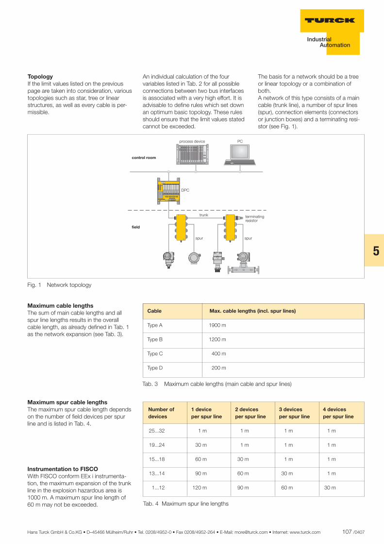
Hans Turck GmbH & Co.KG • D–45466 Mülheim/Ruhr • Tel. 0208/4952-0 • Fax 0208/4952-264 • E-Mail: [email protected] • Internet: www.turck.com 107 /0407
5
TopologyIf the limit values listed on the previous page are taken into consideration, various topologies such as star, tree or linear structures, as well as every cable is per-missible.
An individual calculation of the four variables listed in Tab. 2 for all possible connections between two bus interfaces is associated with a very high effort. It is advisable to defi ne rules which set down an optimum basic topology. These rules should ensure that the limit values stated cannot be exceeded.
The basis for a network should be a tree or linear topology or a combination of both. A network of this type consists of a main cable (trunk line), a number of spur lines (spur), connection elements (connectors or junction boxes) and a terminating resi-stor (see Fig. 1).
Fig. 1 Network topology
Maximum cable lengthsThe sum of main cable lengths and all spur line lengths results in the overall cable length, as already defi ned in Tab. 1 as the network expansion (see Tab. 3).
Cable Max. cable lengths (incl. spur lines)
Type A 1900 m Type B 1200 m Type C 400 m Type D 200 m
Tab. 3 Maximum cable lengths (main cable and spur lines)
Maximum spur cable lengthsThe maximum spur cable length depends on the number of fi eld devices per spur line and is listed in Tab. 4.
Number of 1 device 2 devices 3 devices 4 devices devices per spur line per spur line per spur line per spur line
25...32 1 m 1 m 1 m 1 m
19...24 30 m 1 m 1 m 1 m
15...18 60 m 30 m 1 m 1 m
13...14 90 m 60 m 30 m 1 m
1...12 120 m 90 m 60 m 30 m
Tab. 4 Maximum spur line lengths
Instrumentation to FISCOWith FISCO conform EEx i instrumenta-tion, the maximum expansion of the trunk line in the explosion hazardous area is 1000 m. A maximum spur line length of 60 m may not be exceeded.
��
���
���� ����
������ ����
�����������
���
������������������
�����
���������������� �������������������������������� ���������������� ���������������� ���������������� ���������������� ���������������� ���������������� �������������������������������� ��������������������������������
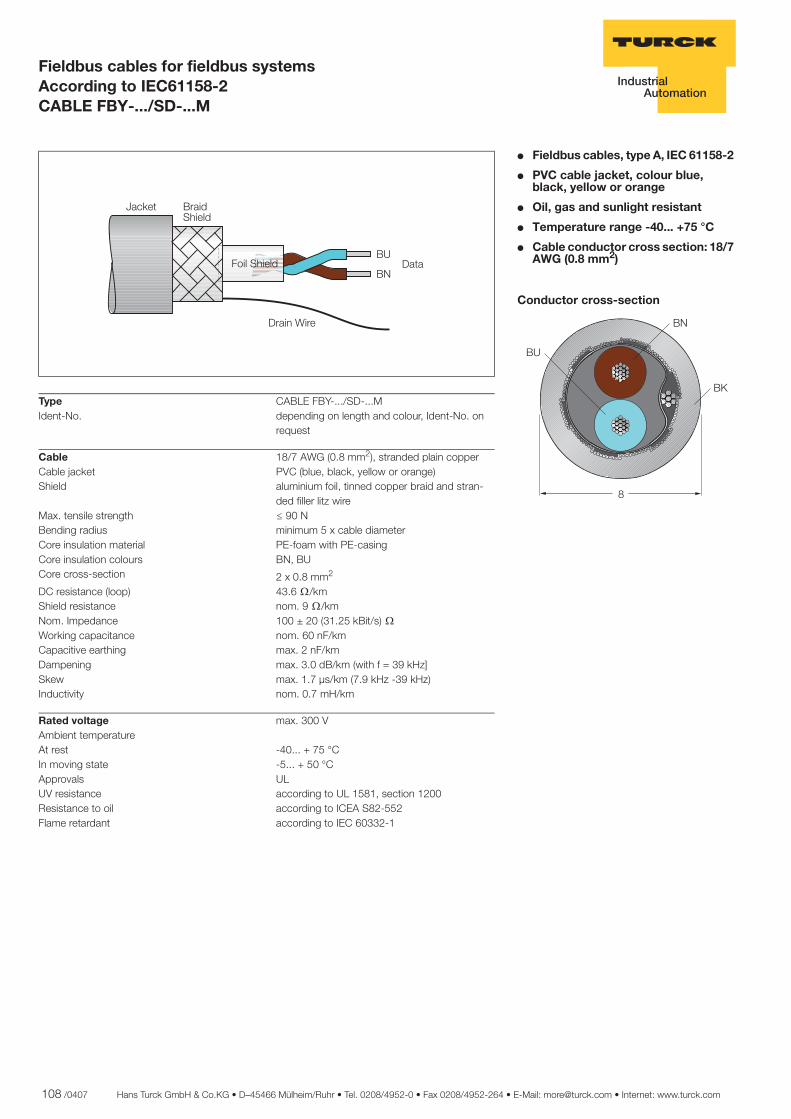
108 /0407 Hans Turck GmbH & Co.KG • D–45466 Mülheim/Ruhr • Tel. 0208/4952-0 • Fax 0208/4952-264 • E-Mail: [email protected] • Internet: www.turck.com
ñ Edition:
Hans Turck GmbH & Co.KG ñ D-45472 Mülheim an der Ruhr ñ Witzlebenstraße 7 ñ Tel. 0208 4952-0 ñ Fax 0208 4952-264 ñ [email protected] ñ www.turck.com
Fieldbus cables for fieldbus systems According to IEC61158-2CABLE FBY-.../SD-...M
� Fieldbus cables, type A, IEC 61158-2
� PVC cable jacket, colour blue, black, yellow or orange
� Oil, gas and sunlight resistant
� Temperature range -40... +75 °C
� Cable conductor cross section: 18/7 AWG (0.8 mm2)
Conductor cross-section
�
��
��
��
Type CABLE FBY-.../SD-...MIdent-No. depending on length and colour, Ident-No. on
request
Cable 18/7 AWG (0.8 mm2), stranded plain copperCable jacket PVC (blue, black, yellow or orange)Shield aluminium foil, tinned copper braid and stran-
ded filler litz wireMax. tensile strength ð 90 NBending radius minimum 5 x cable diameterCore insulation material PE-foam with PE-casingCore insulation colours BN, BUCore cross-section 2 x 0.8 mm2 DC resistance (loop) 43.6 ò/kmShield resistance nom. 9 ò/kmNom. Impedance 100 ± 20 (31.25 kBit/s) òWorking capacitance nom. 60 nF/kmCapacitive earthing max. 2 nF/kmDampening max. 3.0 dB/km (with f = 39 kHz]Skew max. 1.7 µs/km (7.9 kHz -39 kHz)Inductivity nom. 0.7 mH/km
Rated voltage max. 300 VAmbient temperature At rest -40... + 75 °CIn moving state -5... + 50 °CApprovals ULUV resistance according to UL 1581, section 1200Resistance to oil according to ICEA S82-552Flame retardant according to IEC 60332-1
������ ���� ���
������
����� �����
������
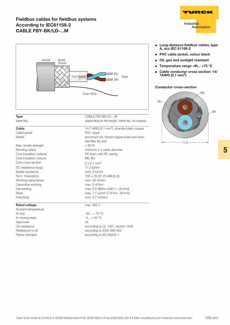
Hans Turck GmbH & Co.KG • D–45466 Mülheim/Ruhr • Tel. 0208/4952-0 • Fax 0208/4952-264 • E-Mail: [email protected] • Internet: www.turck.com 109 /0407
5
ñ Edition:
Hans Turck GmbH & Co.KG ñ D-45472 Mülheim an der Ruhr ñ Witzlebenstraße 7 ñ Tel. 0208 4952-0 ñ Fax 0208 4952-264 ñ [email protected] ñ www.turck.com
Fieldbus cables for fieldbus systems According to IEC61158-2CABLE FBY-BK/LD-...M
� Long-distance fieldbus cables, type A, acc.IEC 61158-2
� PVC cable jacket, colour black
� Oil, gas and sunlight resistant
� Temperature range -40... +75 °C
� Cable conductor cross section: 14/7AWG (2.1 mm2)
Conductor cross-section
����
��
��
��
Type CABLE FBY-BK/LD-...MIdent-No. depending on the length, Ident-No. on request
Cable 14/7 AWG (2.1 mm2), stranded plain copperCable jacket PVC, blackShield aluminium foil, tinned copper braid and stran-
ded filler litz wireMax. tensile strength ð 90 NBending radius minimum 5 x cable diameterCore insulation material PE-foam with PE-casingCore insulation colours BN, BUCore cross-section 2 x 2.1 mm2 DC resistance (loop) 17.2 ò/kmShield resistance nom. 6 ò/kmNom. Impedance 100 ± 20 (31.25 kBit/s) òWorking capacitance nom. 60 nF/kmCapacitive earthing max. 2 nF/kmDampening max. 3.0 dB/km (with f = 39 kHz]Skew max. 1.7 µs/km (7.9 kHz -39 kHz)Inductivity nom. 0.7 mH/km
Rated voltage max. 300 VAmbient temperature At rest -40... + 75 °CIn moving state -5... + 50 °CApprovals ULUV resistance according to UL 1581, section 1200Resistance to oil according to ICEA S82-552Flame retardant according to IEC 60332-1
�� � ������� ��
��������
�������� ����
����
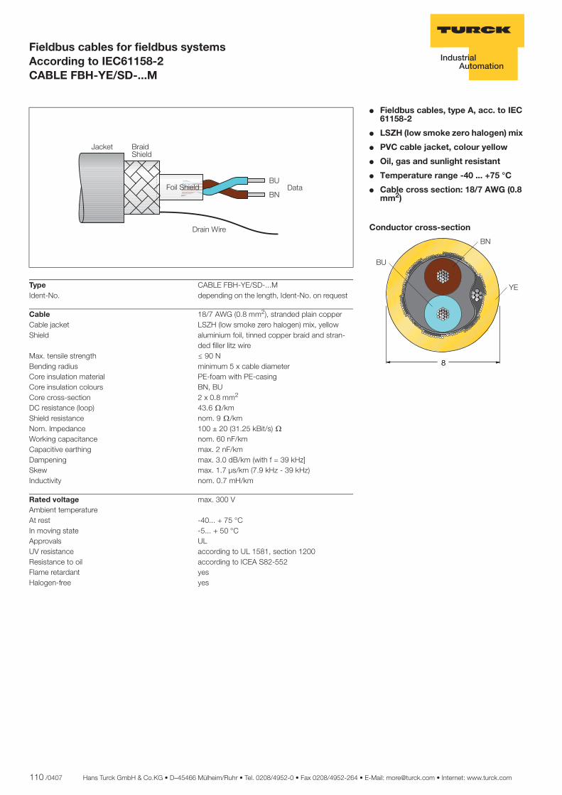
110 /0407 Hans Turck GmbH & Co.KG • D–45466 Mülheim/Ruhr • Tel. 0208/4952-0 • Fax 0208/4952-264 • E-Mail: [email protected] • Internet: www.turck.com
ñ Edition:
Hans Turck GmbH & Co.KG ñ D-45472 Mülheim an der Ruhr ñ Witzlebenstraße 7 ñ Tel. 0208 4952-0 ñ Fax 0208 4952-264 ñ [email protected] ñ www.turck.com
Fieldbus cables for fieldbus systems According to IEC61158-2CABLE FBH-YE/SD-...M
� Fieldbus cables, type A, acc. to IEC 61158-2
� LSZH (low smoke zero halogen) mix
� PVC cable jacket, colour yellow
� Oil, gas and sunlight resistant
� Temperature range -40 ... +75 °C
� Cable cross section: 18/7 AWG (0.8 mm2)
Conductor cross-section
�
��
�
��
��
Type CABLE FBH-YE/SD-...MIdent-No. depending on the length, Ident-No. on request
Cable 18/7 AWG (0.8 mm2), stranded plain copperCable jacket LSZH (low smoke zero halogen) mix, yellowShield aluminium foil, tinned copper braid and stran-
ded filler litz wireMax. tensile strength ð 90 NBending radius minimum 5 x cable diameterCore insulation material PE-foam with PE-casingCore insulation colours BN, BUCore cross-section 2 x 0.8 mm2 DC resistance (loop) 43.6 ò/kmShield resistance nom. 9 ò/kmNom. Impedance 100 ± 20 (31.25 kBit/s) òWorking capacitance nom. 60 nF/kmCapacitive earthing max. 2 nF/kmDampening max. 3.0 dB/km (with f = 39 kHz]Skew max. 1.7 µs/km (7.9 kHz - 39 kHz)Inductivity nom. 0.7 mH/km
Rated voltage max. 300 VAmbient temperature At rest -40... + 75 °CIn moving state -5... + 50 °CApprovals ULUV resistance according to UL 1581, section 1200Resistance to oil according to ICEA S82-552Flame retardant yesHalogen-free yes
������ ���� ���
������
����� �����
������
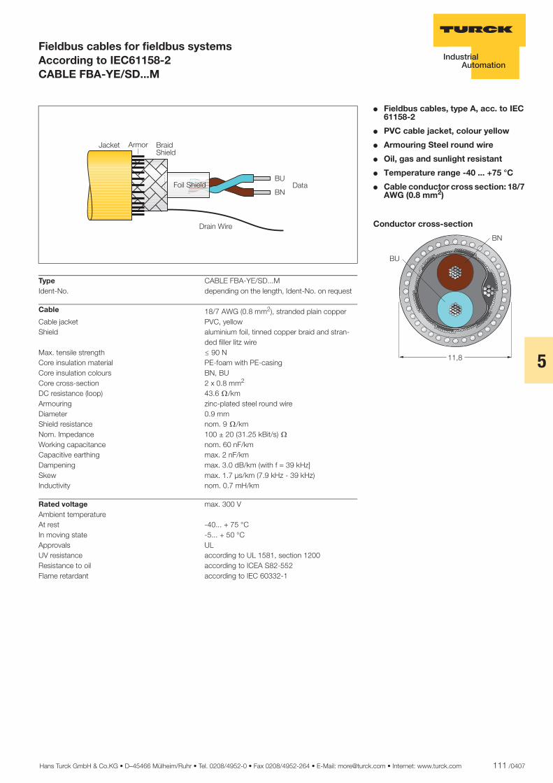
Hans Turck GmbH & Co.KG • D–45466 Mülheim/Ruhr • Tel. 0208/4952-0 • Fax 0208/4952-264 • E-Mail: [email protected] • Internet: www.turck.com 111 /0407
5
ñ Edition:
Hans Turck GmbH & Co.KG ñ D-45472 Mülheim an der Ruhr ñ Witzlebenstraße 7 ñ Tel. 0208 4952-0 ñ Fax 0208 4952-264 ñ [email protected] ñ www.turck.com
Fieldbus cables for fieldbus systems According to IEC61158-2CABLE FBA-YE/SD...M
� Fieldbus cables, type A, acc. to IEC 61158-2
� PVC cable jacket, colour yellow
� Armouring Steel round wire
� Oil, gas and sunlight resistant
� Temperature range -40 ... +75 °C
� Cable conductor cross section: 18/7 AWG (0.8 mm2)
Conductor cross-section
��
��
����
Type CABLE FBA-YE/SD...MIdent-No. depending on the length, Ident-No. on request
Cable 18/7 AWG (0.8 mm2), stranded plain copperCable jacket PVC, yellowShield aluminium foil, tinned copper braid and stran-
ded filler litz wireMax. tensile strength ð 90 NCore insulation material PE-foam with PE-casingCore insulation colours BN, BUCore cross-section 2 x 0.8 mm2 DC resistance (loop) 43.6 ò/kmArmouring zinc-plated steel round wireDiameter 0.9 mmShield resistance nom. 9 ò/kmNom. Impedance 100 ± 20 (31.25 kBit/s) òWorking capacitance nom. 60 nF/kmCapacitive earthing max. 2 nF/kmDampening max. 3.0 dB/km (with f = 39 kHz]Skew max. 1.7 µs/km (7.9 kHz - 39 kHz)Inductivity nom. 0.7 mH/km
Rated voltage max. 300 VAmbient temperature At rest -40... + 75 °CIn moving state -5... + 50 °CApprovals ULUV resistance according to UL 1581, section 1200Resistance to oil according to ICEA S82-552Flame retardant according to IEC 60332-1
������ ���� ���
������
����� �����
������
���
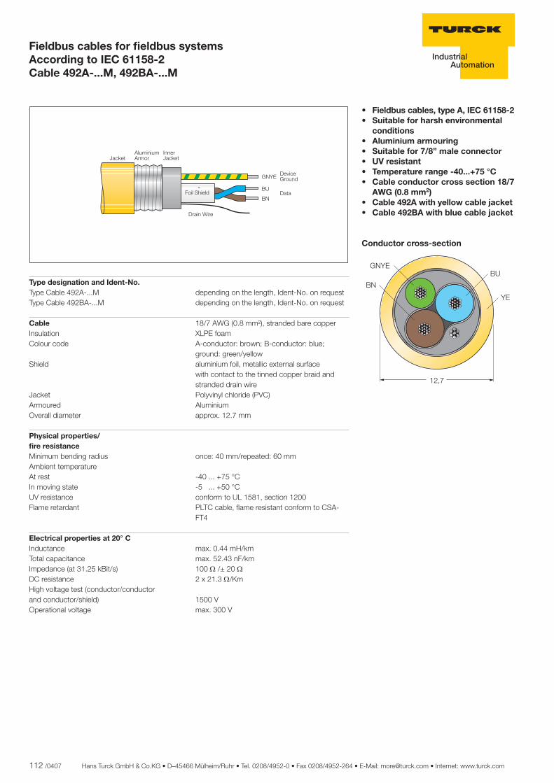
112 /0407 Hans Turck GmbH & Co.KG • D–45466 Mülheim/Ruhr • Tel. 0208/4952-0 • Fax 0208/4952-264 • E-Mail: [email protected] • Internet: www.turck.com
Fieldbus cables for fi eldbus systems According to IEC 61158-2 Cable 492A-...M, 492BA-...M
Type designation and Ident-No. Type Cable 492A-...M depending on the length, Ident-No. on request Type Cable 492BA-...M depending on the length, Ident-No. on request
Cable 18/7 AWG (0.8 mm²), stranded bare copperInsulation XLPE foamColour code A-conductor: brown; B-conductor: blue; ground: green/yellowShield aluminium foil, metallic external surface with contact to the tinned copper braid and stranded drain wireJacket Polyvinyl chloride (PVC) Armoured AluminiumOverall diameter approx. 12.7 mm
Physical properties/ fi re resistance Minimum bending radius once: 40 mm/repeated: 60 mm Ambient temperature At rest -40 ... +75 °C In moving state -5 ... +50 °CUV resistance conform to UL 1581, section 1200Flame retardant PLTC cable, fl ame resistant conform to CSA- FT4
Electrical properties at 20° C Inductance max. 0.44 mH/kmTotal capacitance max. 52.43 nF/kmImpedance (at 31.25 kBit/s) 100 Ω /± 20 ΩDC resistance 2 x 21.3 Ω/Km High voltage test (conductor/conductor and conductor/shield) 1500 VOperational voltage max. 300 V
• Fieldbus cables, type A, IEC 61158-2• Suitable for harsh environmental conditions• Aluminium armouring• Suitable for 7/8” male connector• UV resistant• Temperature range -40...+75 °C• Cable conductor cross section 18/7 AWG (0.8 mm2)• Cable 492A with yellow cable jacket• Cable 492BA with blue cable jacket
Conductor cross-section
���������
���� ���� ������
��
���� ����������
��������������
��������������
����
��
��
��
� !"
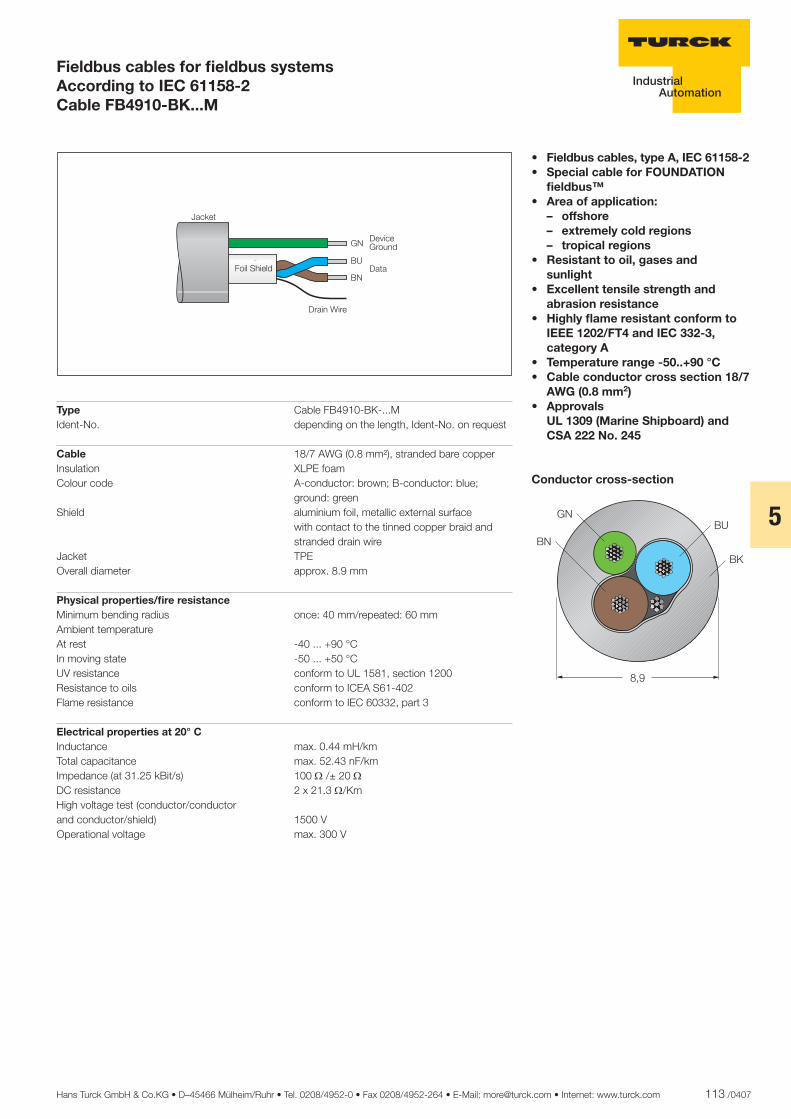
Hans Turck GmbH & Co.KG • D–45466 Mülheim/Ruhr • Tel. 0208/4952-0 • Fax 0208/4952-264 • E-Mail: [email protected] • Internet: www.turck.com 113 /0407
5
Fieldbus cables for fi eldbus systems According to IEC 61158-2 Cable FB4910-BK...M
• Fieldbus cables, type A, IEC 61158-2• Special cable for FOUNDATION fi eldbus™• Area of application: – offshore – extremely cold regions – tropical regions• Resistant to oil, gases and sunlight • Excellent tensile strength and abrasion resistance• Highly fl ame resistant conform to IEEE 1202/FT4 and IEC 332-3, category A• Temperature range -50..+90 °C• Cable conductor cross section 18/7 AWG (0.8 mm2)• Approvals UL 1309 (Marine Shipboard) and CSA 222 No. 245
Conductor cross-section
�����
���������
���� ���� ����
������������
��
��
Type Cable FB4910-BK-...M Ident-No. depending on the length, Ident-No. on request
Cable 18/7 AWG (0.8 mm²), stranded bare copperInsulation XLPE foamColour code A-conductor: brown; B-conductor: blue; ground: greenShield aluminium foil, metallic external surface with contact to the tinned copper braid and stranded drain wireJacket TPE Overall diameter approx. 8.9 mm
Physical properties/fi re resistance Minimum bending radius once: 40 mm/repeated: 60 mmAmbient temperature At rest -40 ... +90 °CIn moving state -50 ... +50 °CUV resistance conform to UL 1581, section 1200Resistance to oils conform to ICEA S61-402Flame resistance conform to IEC 60332, part 3
Electrical properties at 20° C Inductance max. 0.44 mH/kmTotal capacitance max. 52.43 nF/kmImpedance (at 31.25 kBit/s) 100 Ω /± 20 ΩDC resistance 2 x 21.3 Ω/Km High voltage test (conductor/conductor and conductor/shield) 1500 VOperational voltage max. 300 V
��
��
��
�#
$!%

114 /0407 Hans Turck GmbH & Co.KG • D–45466 Mülheim/Ruhr • Tel. 0208/4952-0 • Fax 0208/4952-264 • E-Mail: [email protected] • Internet: www.turck.com
* valid for deliveries within the European Union (EU)
1. Workday
5. Workday*
Ordering until 12 p.m.
Production
Delivery 3 workdays after ordering
Arrival at the customer
JUST IN TIME!Ideally the length of the cord set is adjusted according to the requirements of the plant. For this reason TURCK now offers a Just-in-Time-delivery service (JIT) for premoulded cables.
The new JIT-5D-Programmefor perfect connections:• Just-in-Time delivery within 5 days only• Free choice of cable length• Premoulded fi eldbus and power cables • High fl exibility with respect to planning and mounting of your application• High cost savings
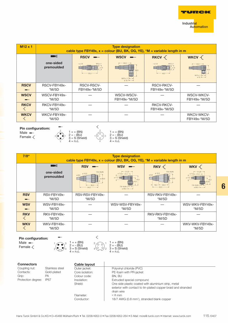
Hans Turck GmbH & Co.KG • D–45466 Mülheim/Ruhr • Tel. 0208/4952-0 • Fax 0208/4952-264 • E-Mail: [email protected] • Internet: www.turck.com 115 /0407
6
Cable layoutOuter jacket: Polyvinyl chloride (PVC)Core isolation: PE-foam with PR-jacketColour code: BN, BUInsolation: Extruded special compoundShield: One side plastic coated with aluminium strip, metal exterior with contact to tin-plated copper braid and stranded drain wireDiameter: ≤ 8 mmConductor: 18/7 AWG (0.8 mm2), stranded blank copper
ConnectorsCoupling nut: Stainless steelContacts: Gold-platedGrip: PAProtection degree: IP67
&
� '
�
'
&
�
'
&
Pin confi guratiom:MalewFemale v
M12 x 1 Type designationcable type FBY49x, x = colour (BU, BK, OG, YE), *M = variable length in m
m RSCV w WSCV w RKCV v WKCV vone-sided
premoulded
RSCV w
RSCV-FBY49x-*M/5D
RSCV-RSCV-FBY49x-*M/5D
— RSCV-RKCV-FBY49x-*M/5D
—
WSCV w
WSCV-FBY49x-*M/5D
— WSCV-WSCV-FBY49x-*M/5D
— WSCV-WKCV-FBY49x-*M/5D
RKCV v
RKCV-FBY49x-*M/5D
— — RKCV-RKCV-FBY49x-*M/5D
—
WKCV v
WKCV-FBY49x-*M/5D
— — — WKCV-WKCV-FBY49x-*M/5D
7/8“ Type designationcable type FBY49x, x = colour (BU, BK, OG, YE), *M = variable length in m
m RSV w WSV w RKV v WKV vone-sided
premoulded
RSV w
RSV-FBY49x-*M/5D
RSV-RSV-FBY49x-*M/5D
— RSV-RKV-FBY49x-*M/5D
—
WSV w
WSV-FBY49x-*M/5D
— WSV-WSV-FBY49x-*M/5D
— WSV-WKV-FBY49x-*M/5D
RKV v
RKV-FBY49x-*M/5D
— — RKV-RKV-FBY49x-*M/5D
—
WKV v
WKV-FBY49x-*M/5D
— — — WKV-WKV-FBY49x-*M/5D
&
' �
1 = + (BN)2 = - (BU)3 = S (Shield)4 = n.c.
w
1 = + (BN)2 = - (BU)3 = S (Shield)4 = n.c.
v
Pin confi guration:MalewFemale v
1 = + (BN)2 = - (BU)3 = S (Shield)4 = n.c.
w
1 = + (BN)2 = - (BU)3 = S (Shield)4 = n.c.
v
(&!)'*!)
"+$,�*��
-� *!)
-�$!(-��(!(
��������
���� �
������
����������
���
��-�"!* .� �/��
((!
-��(
'$!(
.� �/��-��(
''!( ��-�"!* .� �/��
&$!(
-��(' !)
.� �/��-��(
''!(
(�! (&�!)
"+$,�*��-� *!)
-�"!'
-��"!(&'!(
'&!)
(�! (&�!)
"+$,�*��-� *!)
-�"!'
-��"!(&)!)
')!((
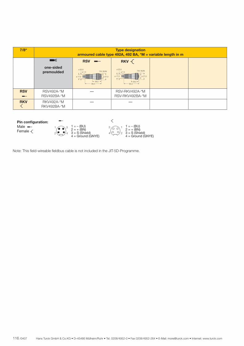
116 /0407 Hans Turck GmbH & Co.KG • D–45466 Mülheim/Ruhr • Tel. 0208/4952-0 • Fax 0208/4952-264 • E-Mail: [email protected] • Internet: www.turck.com
Note: This fi eld-wireable fi eldbus cable is not included in the JIT-5D-Programme.
7/8“ Type designationarmoured cable type 492A, 492 BA, *M = variable length in m
m RSV w RKV vone-sided
premoulded
RSV w
RSV492A-*MRSV492BA-*M
— RSV-RKV492A-*MRSV-RKV492BA-*M
RKV v
RKV492A-*MRKV492BA-*M
— —
*(!) %!)
"+$,�*��
-� "!)
-�"!'
-��"!(
-� )!(
*$!('*!)
"+$,�*��
-� "!)
-�"!'
-��"!(
-� )!(
�
'
&
�
'
&
Pin confi guration:MalewFemale v
1 = – (BU)2 = + (BN)3 = S (Shield)4 = Ground (GNYE)
w
1 = – (BU)2 = + (BN)3 = S (Shield)4 = Ground (GNYE)
v
Hans Turck GmbH & Co.KG • D–45466 Mülheim/Ruhr • Tel. 0208/4952-0 • Fax 0208/4952-264 • E-Mail: [email protected] • Internet: www.turck.com 117 /0407
6
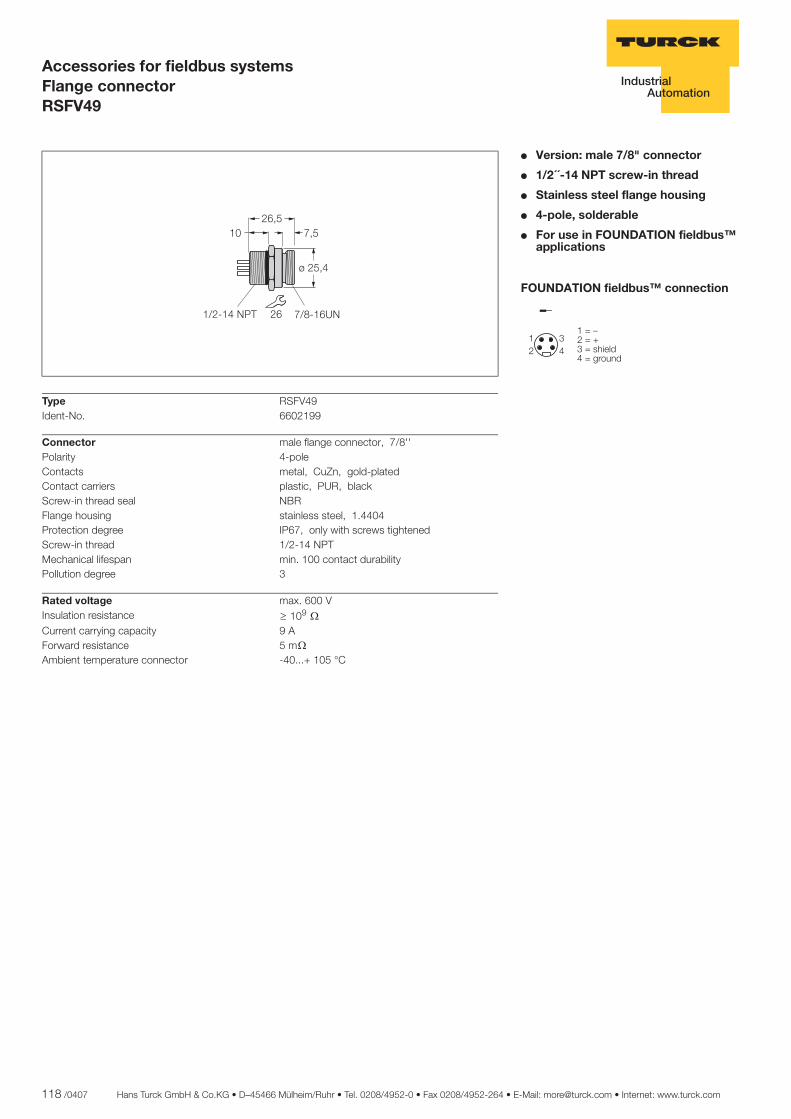
118 /0407 Hans Turck GmbH & Co.KG • D–45466 Mülheim/Ruhr • Tel. 0208/4952-0 • Fax 0208/4952-264 • E-Mail: [email protected] • Internet: www.turck.com
ñ Edition:
Hans Turck GmbH & Co.KG ñ D-45472 Mülheim an der Ruhr ñ Witzlebenstraße 7 ñ Tel. 0208 4952-0 ñ Fax 0208 4952-264 ñ [email protected] ñ www.turck.com
Accessories for fieldbus systemsFlange connectorRSFV49
� Version: male 7/8" connector
� 1/2´´-14 NPT screw-in thread
� Stainless steel flange housing
� 4-pole, solderable
� For use in FOUNDATION fieldbus™ applications
FOUNDATION fieldbus™ connection
��
��
��������������� ������������
Type RSFV49Ident-No. 6602199
Connector male flange connector, 7/8''Polarity 4-poleContacts metal, CuZn, gold-platedContact carriers plastic, PUR, blackScrew-in thread seal NBRFlange housing stainless steel, 1.4404Protection degree IP67, only with screws tightenedScrew-in thread 1/2-14 NPTMechanical lifespan min. 100 contact durabilityPollution degree 3
Rated voltage max. 600 VInsulation resistance ï 109 òCurrent carrying capacity 9 AForward resistance 5 mò
Ambient temperature connector -40...+ 105 °C
������ ���
����
�� �������������� ��
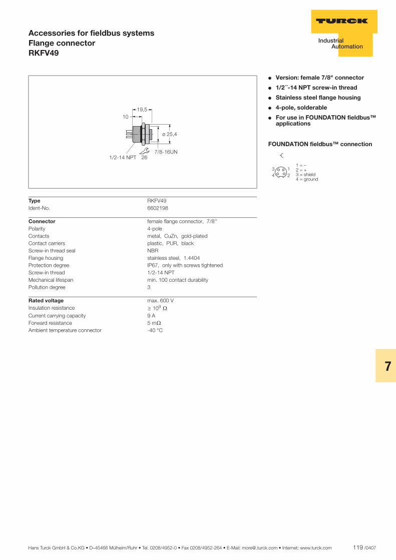
Hans Turck GmbH & Co.KG • D–45466 Mülheim/Ruhr • Tel. 0208/4952-0 • Fax 0208/4952-264 • E-Mail: [email protected] • Internet: www.turck.com 119 /0407
7
ñ Edition:
Hans Turck GmbH & Co.KG ñ D-45472 Mülheim an der Ruhr ñ Witzlebenstraße 7 ñ Tel. 0208 4952-0 ñ Fax 0208 4952-264 ñ [email protected] ñ www.turck.com
Accessories for fieldbus systemsFlange connectorRKFV49
� Version: female 7/8" connector
� 1/2´´-14 NPT screw-in thread
� Stainless steel flange housing
� 4-pole, solderable
� For use in FOUNDATION fieldbus™ applications
FOUNDATION fieldbus™ connection
�
��
��
��������������� ������������
Type RKFV49Ident-No. 6602198
Connector female flange connector, 7/8''Polarity 4-poleContacts metal, CuZn, gold-platedContact carriers plastic, PUR, blackScrew-in thread seal NBRFlange housing stainless steel, 1.4404Protection degree IP67, only with screws tightenedScrew-in thread 1/2-14 NPTMechanical lifespan min. 100 contact durabilityPollution degree 3
Rated voltage max. 600 VInsulation resistance ï 109 òCurrent carrying capacity 9 AForward resistance 5 mò
Ambient temperature connector -40 °C
������
����
����� �� ��������
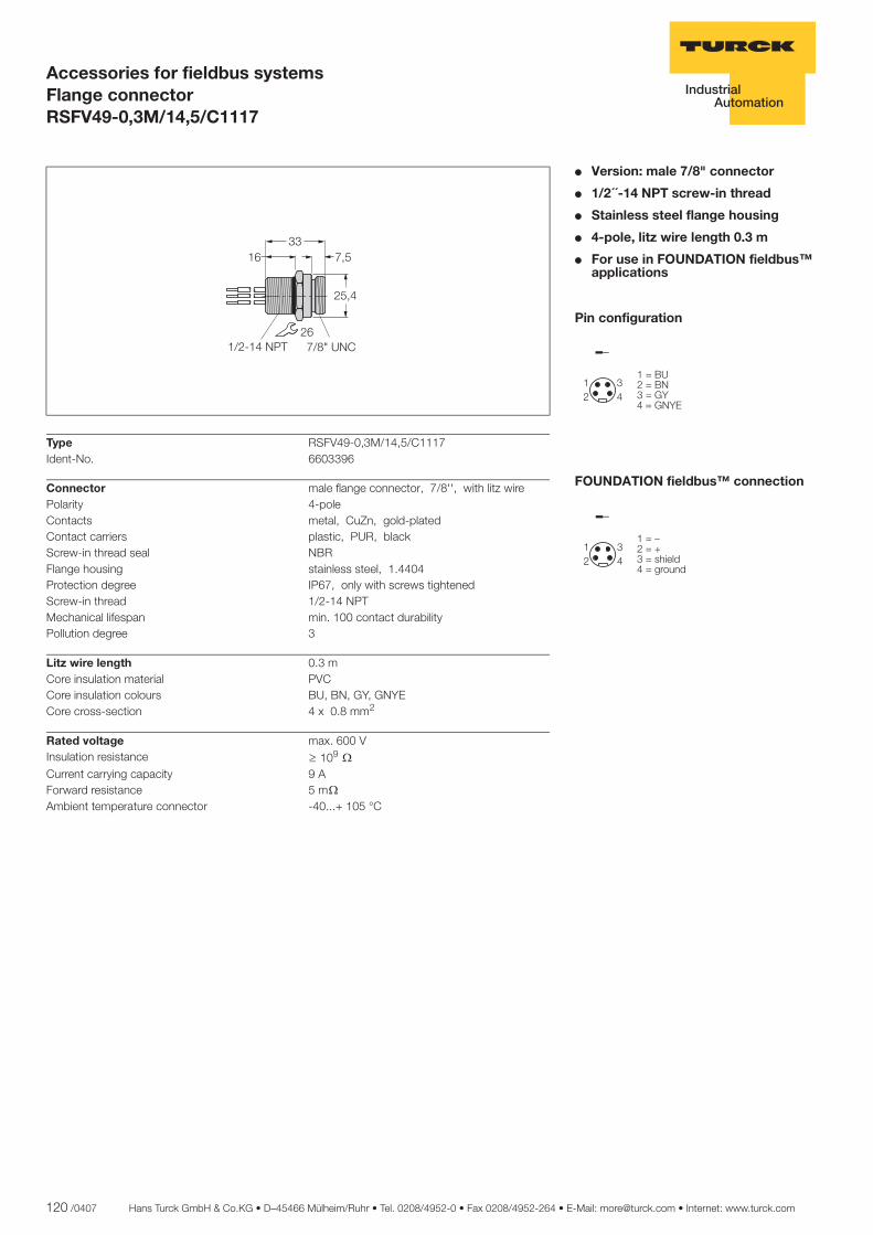
120 /0407 Hans Turck GmbH & Co.KG • D–45466 Mülheim/Ruhr • Tel. 0208/4952-0 • Fax 0208/4952-264 • E-Mail: [email protected] • Internet: www.turck.com
ñ Edition:
Hans Turck GmbH & Co.KG ñ D-45472 Mülheim an der Ruhr ñ Witzlebenstraße 7 ñ Tel. 0208 4952-0 ñ Fax 0208 4952-264 ñ [email protected] ñ www.turck.com
Accessories for fieldbus systemsFlange connectorRSFV49-0,3M/14,5/C1117
� Version: male 7/8" connector
� 1/2´´-14 NPT screw-in thread
� Stainless steel flange housing
� 4-pole, litz wire length 0.3 m
� For use in FOUNDATION fieldbus™ applications
Pin configuration
FOUNDATION fieldbus™ connection
��
��
����������������������
��
��
��������������� ������������
Type RSFV49-0,3M/14,5/C1117Ident-No. 6603396
Connector male flange connector, 7/8'', with litz wirePolarity 4-poleContacts metal, CuZn, gold-platedContact carriers plastic, PUR, blackScrew-in thread seal NBRFlange housing stainless steel, 1.4404Protection degree IP67, only with screws tightenedScrew-in thread 1/2-14 NPTMechanical lifespan min. 100 contact durabilityPollution degree 3
Litz wire length 0.3 mCore insulation material PVCCore insulation colours BU, BN, GY, GNYECore cross-section 4 x 0.8 mm2
Rated voltage max. 600 VInsulation resistance ï 109 òCurrent carrying capacity 9 AForward resistance 5 mò
Ambient temperature connector -40...+ 105 °C
���� ���
���
��� ������� ��� ��

Hans Turck GmbH & Co.KG • D–45466 Mülheim/Ruhr • Tel. 0208/4952-0 • Fax 0208/4952-264 • E-Mail: [email protected] • Internet: www.turck.com 121 /0407
7
ñ Edition:
Hans Turck GmbH & Co.KG ñ D-45472 Mülheim an der Ruhr ñ Witzlebenstraße 7 ñ Tel. 0208 4952-0 ñ Fax 0208 4952-264 ñ [email protected] ñ www.turck.com
Accessories for fieldbus systemsFlange connectorRKFV49-0,3M/14,5
� Version: female 7/8" connector
� 1/2´´-14 NPT screw-in thread
� Stainless steel flange housing
� 4-pole, litz wire length 0.3 m
� For use in FOUNDATION fieldbus™ applications
Pin configuration
FOUNDATION fieldbus™ connection
�
��
��
����������������������
�
��
��
��������������� ������������
Type RKFV49-0,3M/14,5Ident-No. 6602475
Connector female flange connector, 7/8'', with litz wirePolarity 4-poleContacts metal, CuZn, gold-platedContact carriers plastic, PUR, blackScrew-in thread seal NBRFlange housing stainless steel, 1.4404Protection degree IP67, only with screws tightenedScrew-in thread 1/2-14 NPTMechanical lifespan min. 100 contact durabilityPollution degree 3
Litz wire length 0.3 mCore insulation material PVCCore insulation colours BU, BN, GY, GNYECore cross-section 4 x 0.8 mm2
Rated voltage max. 600 VInsulation resistance ï 109 òCurrent carrying capacity 9 AForward resistance 5 mò
Ambient temperature connector -40...+ 105 °C
������
�����
������ � ���������
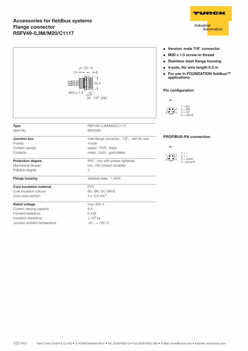
122 /0407 Hans Turck GmbH & Co.KG • D–45466 Mülheim/Ruhr • Tel. 0208/4952-0 • Fax 0208/4952-264 • E-Mail: [email protected] • Internet: www.turck.com
ñ Edition:
Hans Turck GmbH & Co.KG ñ D-45472 Mülheim an der Ruhr ñ Witzlebenstraße 7 ñ Tel. 0208 4952-0 ñ Fax 0208 4952-264 ñ [email protected] ñ www.turck.com
Accessories for fieldbus systemsFlange connectorRSFV49-0,3M/M20/C1117
� Version: male 7/8" connector
� M20 x 1.5 screw-in thread
� Stainless steel flange housing
� 4-pole, litz wire length 0.3 m
� For use in FOUNDATION fieldbus™ applications
Pin configuration
PROFIBUS-PA connection
��
��
����������������������
��
��
��������������� ������������
Type RSFV49-0,3M/M20/C1117Ident-No. 6603583
Junction box male flange connector, 7/8'', with litz wirePolarity 4-poleContact carriers plastic, PUR, blackContacts metal, CuZn, gold-plated
Protection degree IP67, only with screws tightenedMechanical lifespan min. 100 contact durabilityPollution degree 3
Flange housing stainless steel, 1.4404
Core insulation material PVCCore insulation colours BU, BN, GY, GNYECore cross-section 4 x 0.8 mm2
Rated voltage max. 600 VCurrent carrying capacity 9 AForward resistance 5 mò
Insulation resistance ï 109 òJunction ambient temperature -40 ...+ 105 °C
���� �
���
��� ���
��� � ���
��
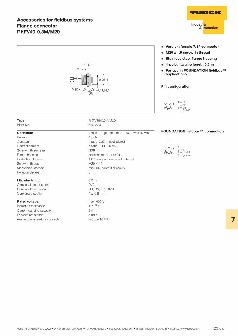
Hans Turck GmbH & Co.KG • D–45466 Mülheim/Ruhr • Tel. 0208/4952-0 • Fax 0208/4952-264 • E-Mail: [email protected] • Internet: www.turck.com 123 /0407
7
ñ Edition:
Hans Turck GmbH & Co.KG ñ D-45472 Mülheim an der Ruhr ñ Witzlebenstraße 7 ñ Tel. 0208 4952-0 ñ Fax 0208 4952-264 ñ [email protected] ñ www.turck.com
Accessories for fieldbus systemsFlange connectorRKFV49-0,3M/M20
� Version: female 7/8" connector
� M20 x 1.5 screw-in thread
� Stainless steel flange housing
� 4-pole, litz wire length 0.3 m
� For use in FOUNDATION fieldbus™ applications
Pin configuration
FOUNDATION fieldbus™ connection
�
��
��
����������������������
�
��
��
���������������� ������������
Type RKFV49-0,3M/M20Ident-No. 6603584
Connector female flange connector, 7/8'', with litz wirePolarity 4-poleContacts metal, CuZn, gold-platedContact carriers plastic, PUR, blackScrew-in thread seal NBRFlange housing stainless steel, 1.4404Protection degree IP67, only with screws tightenedScrew-in thread M20 x 1,5Mechanical lifespan min. 100 contact durabilityPollution degree 3
Litz wire length 0.3 mCore insulation material PVCCore insulation colours BU, BN, GY, GNYECore cross-section 4 x 0.8 mm2
Rated voltage max. 600 VInsulation resistance ï 109 òCurrent carrying capacity 9 AForward resistance 5 mò
Ambient temperature connector -40 ...+ 105 °C
�������� �� ����
���
�����
��
��
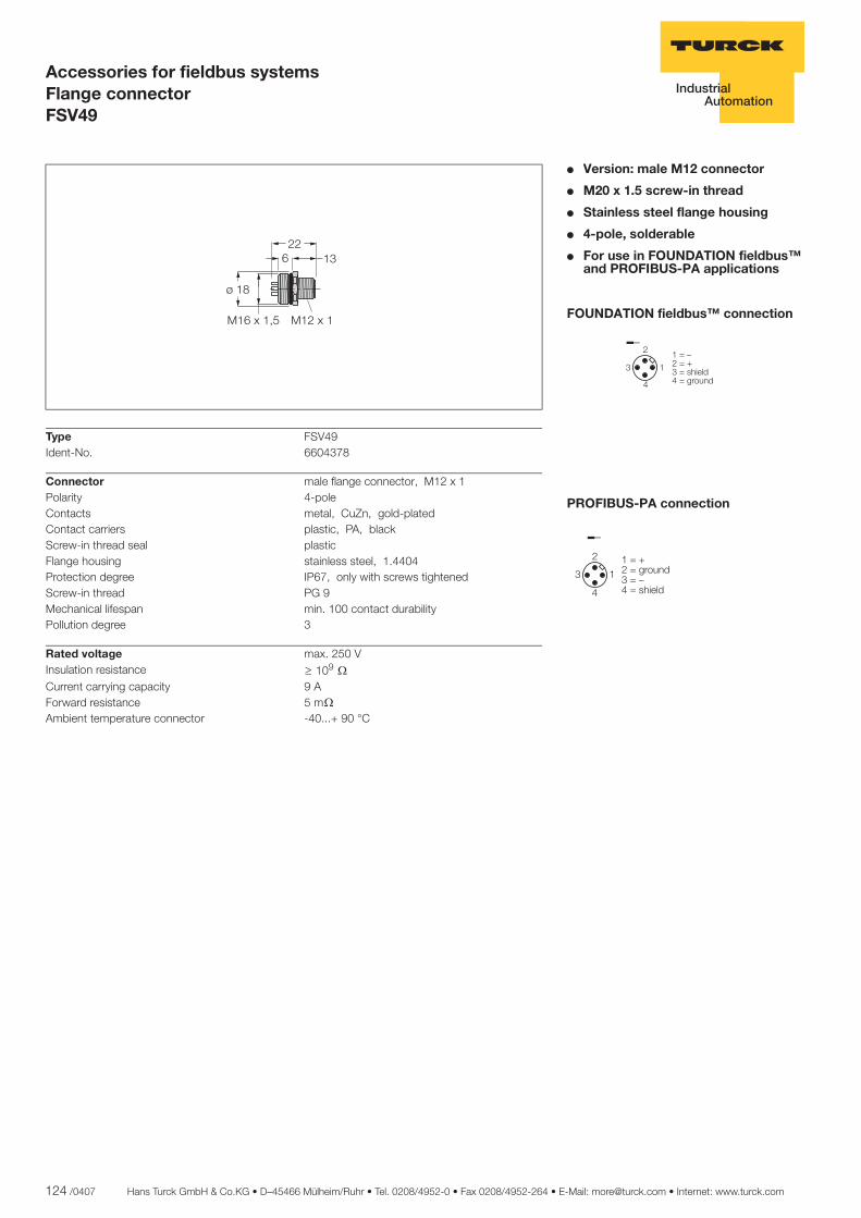
124 /0407 Hans Turck GmbH & Co.KG • D–45466 Mülheim/Ruhr • Tel. 0208/4952-0 • Fax 0208/4952-264 • E-Mail: [email protected] • Internet: www.turck.com
ñ Edition:
Hans Turck GmbH & Co.KG ñ D-45472 Mülheim an der Ruhr ñ Witzlebenstraße 7 ñ Tel. 0208 4952-0 ñ Fax 0208 4952-264 ñ [email protected] ñ www.turck.com
Accessories for fieldbus systemsFlange connectorFSV49
� Version: male M12 connector
� M20 x 1.5 screw-in thread
� Stainless steel flange housing
� 4-pole, solderable
� For use in FOUNDATION fieldbus™ and PROFIBUS-PA applications
FOUNDATION fieldbus™ connection
PROFIBUS-PA connection
�
��
� ��������������� ������������
�
��
� ����������� ����������������
Type FSV49Ident-No. 6604378
Connector male flange connector, M12 x 1Polarity 4-poleContacts metal, CuZn, gold-platedContact carriers plastic, PA, blackScrew-in thread seal plasticFlange housing stainless steel, 1.4404Protection degree IP67, only with screws tightenedScrew-in thread PG 9Mechanical lifespan min. 100 contact durabilityPollution degree 3
Rated voltage max. 250 VInsulation resistance ï 109 òCurrent carrying capacity 9 AForward resistance 5 mò
Ambient temperature connector -40...+ 90 °C
�������
�
���
��������
����
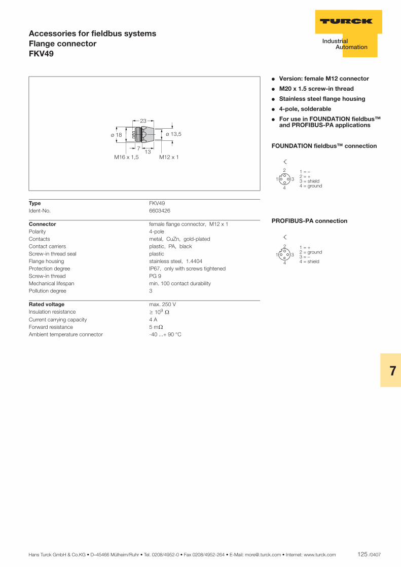
Hans Turck GmbH & Co.KG • D–45466 Mülheim/Ruhr • Tel. 0208/4952-0 • Fax 0208/4952-264 • E-Mail: [email protected] • Internet: www.turck.com 125 /0407
7
ñ Edition:
Hans Turck GmbH & Co.KG ñ D-45472 Mülheim an der Ruhr ñ Witzlebenstraße 7 ñ Tel. 0208 4952-0 ñ Fax 0208 4952-264 ñ [email protected] ñ www.turck.com
Accessories for fieldbus systemsFlange connectorFKV49
� Version: female M12 connector
� M20 x 1.5 screw-in thread
� Stainless steel flange housing
� 4-pole, solderable
� For use in FOUNDATION fieldbus™ and PROFIBUS-PA applications
FOUNDATION fieldbus™ connection
PROFIBUS-PA connection
�
�
�
�
�� ��� ���� ��������� �������
�
�
�
�
�
����������� ����������������
Type FKV49Ident-No. 6603426
Connector female flange connector, M12 x 1Polarity 4-poleContacts metal, CuZn, gold-platedContact carriers plastic, PA, blackScrew-in thread seal plasticFlange housing stainless steel, 1.4404Protection degree IP67, only with screws tightenedScrew-in thread PG 9Mechanical lifespan min. 100 contact durabilityPollution degree 3
Rated voltage max. 250 VInsulation resistance ï 109 òCurrent carrying capacity 4 AForward resistance 5 mò
Ambient temperature connector -40 ...+ 90 °C
�������
����
���
����
�� ����
��
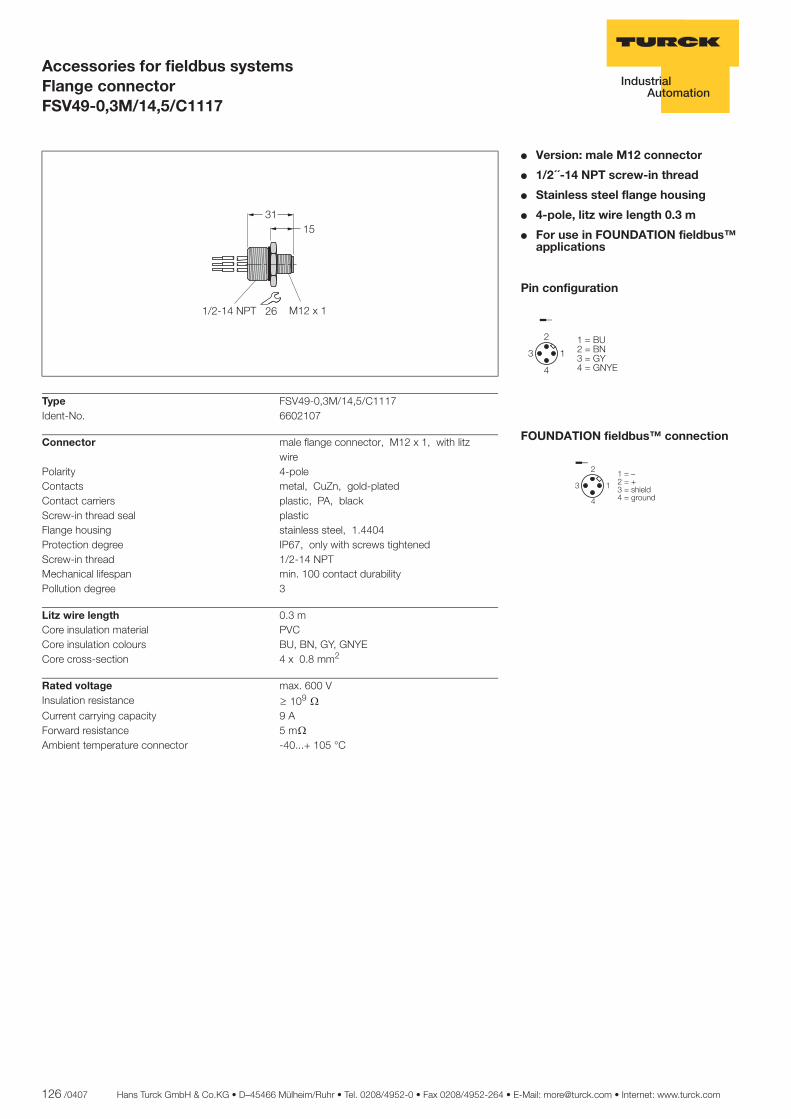
126 /0407 Hans Turck GmbH & Co.KG • D–45466 Mülheim/Ruhr • Tel. 0208/4952-0 • Fax 0208/4952-264 • E-Mail: [email protected] • Internet: www.turck.com
ñ Edition:
Hans Turck GmbH & Co.KG ñ D-45472 Mülheim an der Ruhr ñ Witzlebenstraße 7 ñ Tel. 0208 4952-0 ñ Fax 0208 4952-264 ñ [email protected] ñ www.turck.com
Accessories for fieldbus systemsFlange connectorFSV49-0,3M/14,5/C1117
� Version: male M12 connector
� 1/2´´-14 NPT screw-in thread
� Stainless steel flange housing
� 4-pole, litz wire length 0.3 m
� For use in FOUNDATION fieldbus™ applications
Pin configuration
FOUNDATION fieldbus™ connection
�
��
� ����������������������
�
��
� ��������������� ������������
Type FSV49-0,3M/14,5/C1117Ident-No. 6602107
Connector male flange connector, M12 x 1, with litz wire
Polarity 4-poleContacts metal, CuZn, gold-platedContact carriers plastic, PA, blackScrew-in thread seal plasticFlange housing stainless steel, 1.4404Protection degree IP67, only with screws tightenedScrew-in thread 1/2-14 NPTMechanical lifespan min. 100 contact durabilityPollution degree 3
Litz wire length 0.3 mCore insulation material PVCCore insulation colours BU, BN, GY, GNYECore cross-section 4 x 0.8 mm2
Rated voltage max. 600 VInsulation resistance ï 109 òCurrent carrying capacity 9 AForward resistance 5 mò
Ambient temperature connector -40...+ 105 °C
����
������������� � ��
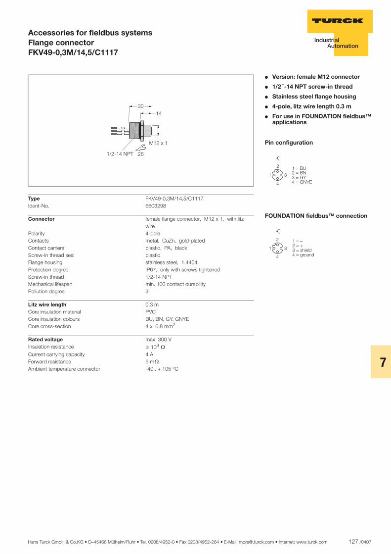
Hans Turck GmbH & Co.KG • D–45466 Mülheim/Ruhr • Tel. 0208/4952-0 • Fax 0208/4952-264 • E-Mail: [email protected] • Internet: www.turck.com 127 /0407
7
ñ Edition:
Hans Turck GmbH & Co.KG ñ D-45472 Mülheim an der Ruhr ñ Witzlebenstraße 7 ñ Tel. 0208 4952-0 ñ Fax 0208 4952-264 ñ [email protected] ñ www.turck.com
Accessories for fieldbus systemsFlange connectorFKV49-0,3M/14,5/C1117
� Version: female M12 connector
� 1/2´´-14 NPT screw-in thread
� Stainless steel flange housing
� 4-pole, litz wire length 0.3 m
� For use in FOUNDATION fieldbus™ applications
Pin configuration
FOUNDATION fieldbus™ connection
�
�
�
�
�����������������������
�
�
�
�
�
�#��#��#�& ��'�#�����'
Type FKV49-0,3M/14,5/C1117Ident-No. 6603298
Connector female flange connector, M12 x 1, with litz wire
Polarity 4-poleContacts metal, CuZn, gold-platedContact carriers plastic, PA, blackScrew-in thread seal plasticFlange housing stainless steel, 1.4404Protection degree IP67, only with screws tightenedScrew-in thread 1/2-14 NPTMechanical lifespan min. 100 contact durabilityPollution degree 3
Litz wire length 0.3 mCore insulation material PVCCore insulation colours BU, BN, GY, GNYECore cross-section 4 x 0.8 mm2
Rated voltage max. 300 VInsulation resistance ï 109 òCurrent carrying capacity 4 AForward resistance 5 mò
Ambient temperature connector -40...+ 105 °C
����
������
������� � ��

128 /0407 Hans Turck GmbH & Co.KG • D–45466 Mülheim/Ruhr • Tel. 0208/4952-0 • Fax 0208/4952-264 • E-Mail: [email protected] • Internet: www.turck.com
ñ Edition:
Hans Turck GmbH & Co.KG ñ D-45472 Mülheim an der Ruhr ñ Witzlebenstraße 7 ñ Tel. 0208 4952-0 ñ Fax 0208 4952-264 ñ [email protected] ñ www.turck.com
Accessories for fieldbus systemsFlange connectorFSV49-0,3M/M20/C1117
� Version: male M12 connector
� M20 x 1.5 screw-in thread
� Stainless steel flange housing
� 4-pole, litz wire length 0.3 m
� For use in FOUNDATION fieldbus™ applications
Pin configuration
FOUNDATION fieldbus™ connection
�
��
� ����������������������
�
��
� ��������������� ������������
Type FSV49-0,3M/M20/C1117Ident-No. 6603682
Connector male flange connector, M12 x 1, with litz wire
Polarity 4-poleContacts metal, CuZn, gold-platedContact carriers plastic, PA, blackScrew-in thread seal plasticFlange housing stainless steel, 1.4404Protection degree IP67, only with screws tightenedScrew-in thread M20 x 1,5Mechanical lifespan min. 100 contact durabilityPollution degree 3
Litz wire length 0.3 mCore insulation material PVCCore insulation colours BU, BN, GY, GNYECore cross-section 4 x 0.8 mm2
Rated voltage max. 600 VInsulation resistance ï 109 òCurrent carrying capacity 9 AForward resistance 5 mò
Ambient temperature connector -40...+ 105 °C
����
��������������� �

Hans Turck GmbH & Co.KG • D–45466 Mülheim/Ruhr • Tel. 0208/4952-0 • Fax 0208/4952-264 • E-Mail: [email protected] • Internet: www.turck.com 129 /0407
7
ñ Edition:
Hans Turck GmbH & Co.KG ñ D-45472 Mülheim an der Ruhr ñ Witzlebenstraße 7 ñ Tel. 0208 4952-0 ñ Fax 0208 4952-264 ñ [email protected] ñ www.turck.com
Accessories for fieldbus systemsFlange connectorFKV49-0,3M/M20/C1117
� Version: female M12 connector
� M20 x 1.5 screw-in thread
� Stainless steel flange housing
� 4-pole, litz wire length 0.3 m
� For use in FOUNDATION fieldbus™ applications
Pin configuration
FOUNDATION fieldbus™ connection
�
�
�
�
�����������������������
�
�
�
�
�
��������������� ������������
Type FKV49-0,3M/M20/C1117Ident-No. 6603683
Connector female flange connector, M12 x 1, with litz wire
Polarity 4-poleContacts metal, CuZn, gold-platedContact carriers plastic, PA, blackScrew-in thread seal plasticFlange housing stainless steel, 1.4404Protection degree IP67, only with screws tightenedScrew-in thread M20 x 1,5Mechanical lifespan min. 100 contact durabilityPollution degree 3
Litz wire length 0.3 mCore insulation material PVCCore insulation colours BU, BN, GY, GNYECore cross-section 4 x 0.8 mm2
Rated voltage max. 300 VInsulation resistance ï 109 òCurrent carrying capacity 4 AForward resistance 5 mò
Ambient temperature connector -40...+ 105 °C
����
�������
������� ��
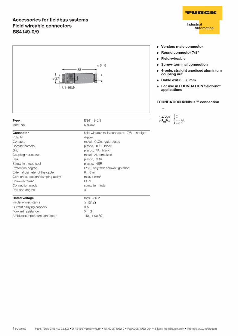
130 /0407 Hans Turck GmbH & Co.KG • D–45466 Mülheim/Ruhr • Tel. 0208/4952-0 • Fax 0208/4952-264 • E-Mail: [email protected] • Internet: www.turck.com
ñ Edition:
Hans Turck GmbH & Co.KG ñ D-45472 Mülheim an der Ruhr ñ Witzlebenstraße 7 ñ Tel. 0208 4952-0 ñ Fax 0208 4952-264 ñ [email protected] ñ www.turck.com
Accessories for fieldbus systemsField wireable connectorsBS4149-0/9
� Version: male connector
� Round connector 7/8"
� Field-wireable
� Screw-terminal connection
� 4-pole, straight anodised aluminium coupling nut
� Cable exit 6 ... 8 mm
� For use in FOUNDATION fieldbus™ applications
FOUNDATION fieldbus™ connection
��
��
��������������� ����������
Type BS4149-0/9Ident-No. 6914521
Connector field-wireable male connector, 7/8'', straightPolarity 4-poleContacts metal, CuZn, gold-platedContact carriers plastic, TPU, blackGrip plastic, PA, blackCoupling nut/screw metal, Al, anodizedSeal plastic, NBRScrew-in thread seal plastic, NBRProtection degree IP67, only with screws tightenedExternal diameter of the cable 6... 8 mmCore cross-section/clamping ability max. 1 mm2
Screw-in thread PG 9Connection mode screw terminalsPollution degree 3
Rated voltage max. 250 VInsulation resistance ï 109 òCurrent carrying capacity 9 AForward resistance 5 mò
Ambient temperature connector -40...+ 90 °C
��
���
������
�����
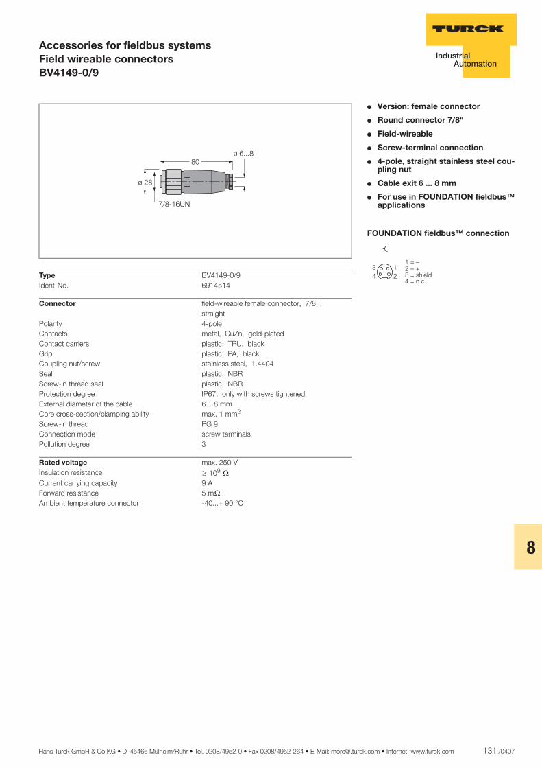
Hans Turck GmbH & Co.KG • D–45466 Mülheim/Ruhr • Tel. 0208/4952-0 • Fax 0208/4952-264 • E-Mail: [email protected] • Internet: www.turck.com 131 /0407
8
ñ Edition:
Hans Turck GmbH & Co.KG ñ D-45472 Mülheim an der Ruhr ñ Witzlebenstraße 7 ñ Tel. 0208 4952-0 ñ Fax 0208 4952-264 ñ [email protected] ñ www.turck.com
Accessories for fieldbus systemsField wireable connectorsBV4149-0/9
� Version: female connector
� Round connector 7/8"
� Field-wireable
� Screw-terminal connection
� 4-pole, straight stainless steel cou-pling nut
� Cable exit 6 ... 8 mm
� For use in FOUNDATION fieldbus™ applications
FOUNDATION fieldbus™ connection
�
��
��
��������������� ����������
Type BV4149-0/9Ident-No. 6914514
Connector field-wireable female connector, 7/8'', straight
Polarity 4-poleContacts metal, CuZn, gold-platedContact carriers plastic, TPU, blackGrip plastic, PA, blackCoupling nut/screw stainless steel, 1.4404Seal plastic, NBRScrew-in thread seal plastic, NBRProtection degree IP67, only with screws tightenedExternal diameter of the cable 6... 8 mmCore cross-section/clamping ability max. 1 mm2
Screw-in thread PG 9Connection mode screw terminalsPollution degree 3
Rated voltage max. 250 VInsulation resistance ï 109 òCurrent carrying capacity 9 AForward resistance 5 mò
Ambient temperature connector -40...+ 90 °C
����
������
��������
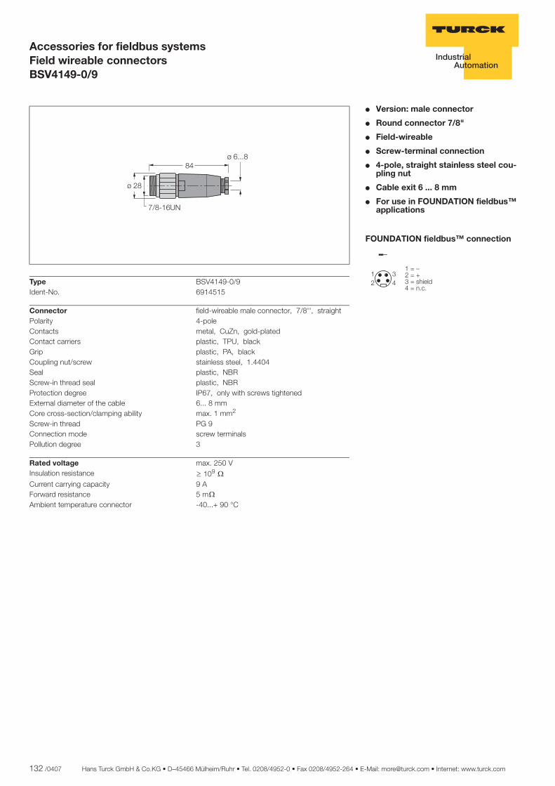
132 /0407 Hans Turck GmbH & Co.KG • D–45466 Mülheim/Ruhr • Tel. 0208/4952-0 • Fax 0208/4952-264 • E-Mail: [email protected] • Internet: www.turck.com
ñ Edition:
Hans Turck GmbH & Co.KG ñ D-45472 Mülheim an der Ruhr ñ Witzlebenstraße 7 ñ Tel. 0208 4952-0 ñ Fax 0208 4952-264 ñ [email protected] ñ www.turck.com
Accessories for fieldbus systemsField wireable connectorsBSV4149-0/9
� Version: male connector
� Round connector 7/8"
� Field-wireable
� Screw-terminal connection
� 4-pole, straight stainless steel cou-pling nut
� Cable exit 6 ... 8 mm
� For use in FOUNDATION fieldbus™ applications
FOUNDATION fieldbus™ connection
��
�
��������� ���� !�"������#�#
Type BSV4149-0/9Ident-No. 6914515
Connector field-wireable male connector, 7/8'', straightPolarity 4-poleContacts metal, CuZn, gold-platedContact carriers plastic, TPU, blackGrip plastic, PA, blackCoupling nut/screw stainless steel, 1.4404Seal plastic, NBRScrew-in thread seal plastic, NBRProtection degree IP67, only with screws tightenedExternal diameter of the cable 6... 8 mmCore cross-section/clamping ability max. 1 mm2
Screw-in thread PG 9Connection mode screw terminalsPollution degree 3
Rated voltage max. 250 VInsulation resistance ï 109 òCurrent carrying capacity 9 AForward resistance 5 mò
Ambient temperature connector -40...+ 90 °C
��
����
��������
�������

Hans Turck GmbH & Co.KG • D–45466 Mülheim/Ruhr • Tel. 0208/4952-0 • Fax 0208/4952-264 • E-Mail: [email protected] • Internet: www.turck.com 133 /0407
8
ñ Edition:
Hans Turck GmbH & Co.KG ñ D-45472 Mülheim an der Ruhr ñ Witzlebenstraße 7 ñ Tel. 0208 4952-0 ñ Fax 0208 4952-264 ñ [email protected] ñ www.turck.com
Accessories for fieldbus systemsField wireable connectorsBV4149-0/16
� Version: female connector
� Round connector 7/8"
� Field-wireable
� Screw-terminal connection
� 4-pole, straight stainless steel cou-pling nut
� Cable exit 12 ... 14 mm
� For use in FOUNDATION fieldbus™ applications
FOUNDATION fieldbus™ connection
�
��
��
����� ����������
Type BV4149-0/16Ident-No. 6914532
Connector field-wireable female connector, 7/8'', straight
Polarity 4-poleContacts metal, CuZn, gold-platedContact carriers plastic, TPU, blackGrip plastic, PA, blackCoupling nut/screw stainless steel, 1.4404Seal plastic, NBRScrew-in thread seal plastic, NBRProtection degree IP67, only with screws tightenedExternal diameter of the cable 12... 14 mmCore cross-section/clamping ability max. 1 mm2
Screw-in thread PG 16Connection mode screw terminalsPollution degree 3
Rated voltage max. 250 VInsulation resistance ï 109 òCurrent carrying capacity 9 AForward resistance 5 mò
Ambient temperature connector -40 ...+ 90 °C
� �
�������
� �������

134 /0407 Hans Turck GmbH & Co.KG • D–45466 Mülheim/Ruhr • Tel. 0208/4952-0 • Fax 0208/4952-264 • E-Mail: [email protected] • Internet: www.turck.com
ñ Edition:
Hans Turck GmbH & Co.KG ñ D-45472 Mülheim an der Ruhr ñ Witzlebenstraße 7 ñ Tel. 0208 4952-0 ñ Fax 0208 4952-264 ñ [email protected] ñ www.turck.com
Accessories for fieldbus systemsField wireable connectorsBSV4149-0/16
� Version: male connector
� Round connector 7/8"
� Field-wireable
� Screw-terminal connection
� 4-pole, straight stainless steel cou-pling nut
� Cable exit 12 ... 14 mm
� For use in FOUNDATION fieldbus™ applications
FOUNDATION fieldbus™ connection
��
��
��������������� ����������
Type BSV4149-0/16Ident-No. 6914533
Connector field-wireable male connector, 7/8'', straightPolarity 4-poleContacts metal, CuZn, gold-platedContact carriers plastic, TPU, blackGrip plastic, PA, blackCoupling nut/screw stainless steel, 1.4404Seal plastic, NBRScrew-in thread seal plastic, NBRProtection degree IP67, only with screws tightenedExternal diameter of the cable 12... 14 mmCore cross-section/clamping ability max. 1 mm2
Screw-in thread PG 16Connection mode screw terminalsPollution degree 3
Rated voltage max. 250 VInsulation resistance ï 109 òCurrent carrying capacity 9 AForward resistance 5 mò
Ambient temperature connector -40 ...+ 90 °C
��
����
������
��� �

Hans Turck GmbH & Co.KG • D–45466 Mülheim/Ruhr • Tel. 0208/4952-0 • Fax 0208/4952-264 • E-Mail: [email protected] • Internet: www.turck.com 135 /0407
8
ñ Edition:
Hans Turck GmbH & Co.KG ñ D-45472 Mülheim an der Ruhr ñ Witzlebenstraße 7 ñ Tel. 0208 4952-0 ñ Fax 0208 4952-264 ñ [email protected] ñ www.turck.com
Accessories for fieldbus systemsField wireable connectorsBKV8140-0/9
� Version: female M12 connector
� Field-wireable
� 4-pole, straight stainless steel cou-pling nut
� Cable exit 4 ... 8 mm
� For use in PROFIBUS-PA and FOUNDATION fieldbus™ applica-tions
PROFIBUS-PA connection
FOUNDATION fieldbus™ connection
�
�
�
�
�
������������������� �����
�
�
�
�
�
��������������� ����������
Type BKV8140-0/9Ident-No. 6914538
Connector field-wireable female connector, M12 x 1, straight
Polarity 4-poleContacts metal, CuZn, CuSnZn, Optalloy coatedContact carriers plastic, PA, blackGrip plastic, PA, blackCoupling nut/screw stainless steel, 1.4404Seal plastic, FKM/FPMScrew-in thread seal plastic, NBRProtection degree IP67, only with screws tightenedExternal diameter of the cable 4... 8 mmCore cross-section/clamping ability 0.14... 0.75 mm2
Screw-in thread M12 x 1Connection mode screw terminalsPollution degree 3
Rated voltage max. 250 VInsulation resistance ï 109 òCurrent carrying capacity 4 AForward resistance 5 mò
Ambient temperature connector -25...+ 90 °C
�������
��
����
���
���
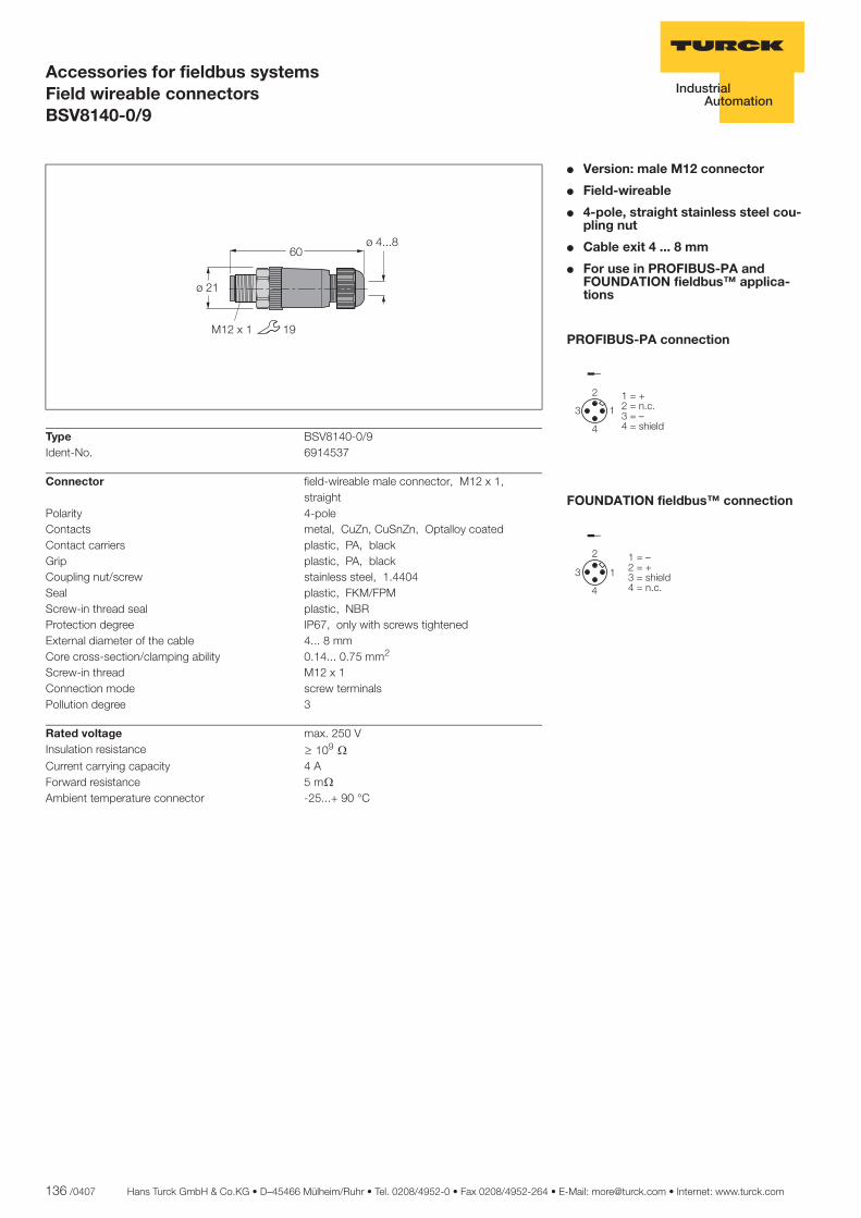
136 /0407 Hans Turck GmbH & Co.KG • D–45466 Mülheim/Ruhr • Tel. 0208/4952-0 • Fax 0208/4952-264 • E-Mail: [email protected] • Internet: www.turck.com
ñ Edition:
Hans Turck GmbH & Co.KG ñ D-45472 Mülheim an der Ruhr ñ Witzlebenstraße 7 ñ Tel. 0208 4952-0 ñ Fax 0208 4952-264 ñ [email protected] ñ www.turck.com
Accessories for fieldbus systemsField wireable connectorsBSV8140-0/9
� Version: male M12 connector
� Field-wireable
� 4-pole, straight stainless steel cou-pling nut
� Cable exit 4 ... 8 mm
� For use in PROFIBUS-PA and FOUNDATION fieldbus™ applica-tions
PROFIBUS-PA connection
FOUNDATION fieldbus™ connection
�
��
� ������������������� �����
�
��
� ��������������� ����������
Type BSV8140-0/9Ident-No. 6914537
Connector field-wireable male connector, M12 x 1, straight
Polarity 4-poleContacts metal, CuZn, CuSnZn, Optalloy coatedContact carriers plastic, PA, blackGrip plastic, PA, blackCoupling nut/screw stainless steel, 1.4404Seal plastic, FKM/FPMScrew-in thread seal plastic, NBRProtection degree IP67, only with screws tightenedExternal diameter of the cable 4... 8 mmCore cross-section/clamping ability 0.14... 0.75 mm2
Screw-in thread M12 x 1Connection mode screw terminalsPollution degree 3
Rated voltage max. 250 VInsulation resistance ï 109 òCurrent carrying capacity 4 AForward resistance 5 mò
Ambient temperature connector -25...+ 90 °C
��
����
������
������
��
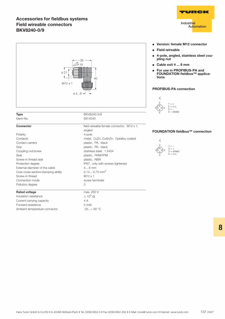
Hans Turck GmbH & Co.KG • D–45466 Mülheim/Ruhr • Tel. 0208/4952-0 • Fax 0208/4952-264 • E-Mail: [email protected] • Internet: www.turck.com 137 /0407
8
ñ Edition:
Hans Turck GmbH & Co.KG ñ D-45472 Mülheim an der Ruhr ñ Witzlebenstraße 7 ñ Tel. 0208 4952-0 ñ Fax 0208 4952-264 ñ [email protected] ñ www.turck.com
Accessories for fieldbus systemsField wireable connectorsBKV8240-0/9
� Version: female M12 connector
� Field-wireable
� 4-pole, angled, stainless steel cou-pling nut
� Cable exit 4 ... 8 mm
� For use in PROFIBUS-PA and FOUNDATION fieldbus™ applica-tions
PROFIBUS-PA connection
FOUNDATION fieldbus™ connection
�
�
�
�
�
����������������������� ��
�
�
�
�
�
��������������� ����������
Type BKV8240-0/9Ident-No. 6914540
Connector field-wireable female connector, M12 x 1, angled
Polarity 4-poleContacts metal, CuZn, CuSnZn, Optalloy coatedContact carriers plastic, PA, blackGrip plastic, PA, blackCoupling nut/screw stainless steel, 1.4404Seal plastic, FKM/FPMScrew-in thread seal plastic, NBRProtection degree IP67, only with screws tightenedExternal diameter of the cable 4... 8 mmCore cross-section/clamping ability 0.14... 0.75 mm2
Screw-in thread M12 x 1Connection mode screw terminalsPollution degree 3
Rated voltage max. 250 VInsulation resistance ï 109 òCurrent carrying capacity 4 AForward resistance 5 mò
Ambient temperature connector -25...+ 90 °C
��
�������
����
��
�� �
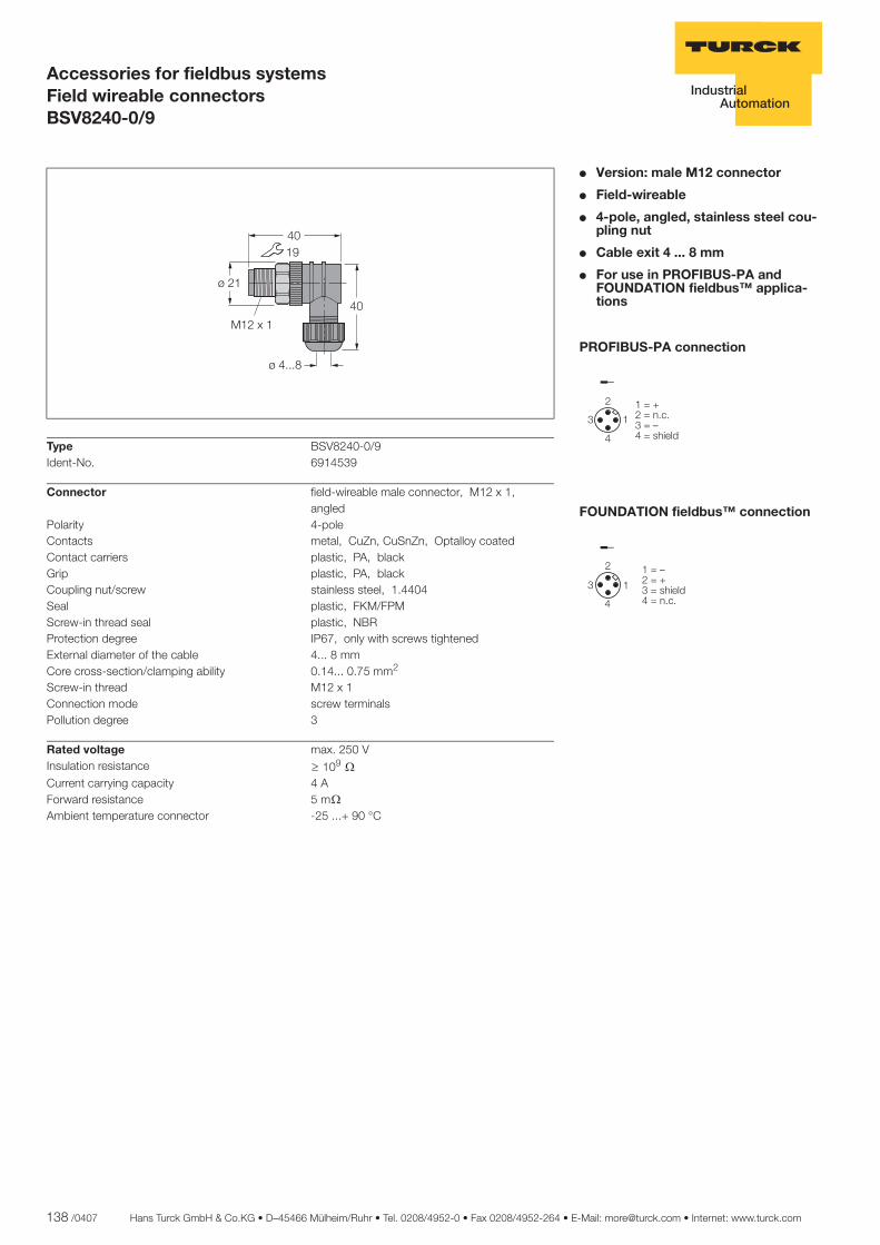
138 /0407 Hans Turck GmbH & Co.KG • D–45466 Mülheim/Ruhr • Tel. 0208/4952-0 • Fax 0208/4952-264 • E-Mail: [email protected] • Internet: www.turck.com
ñ Edition:
Hans Turck GmbH & Co.KG ñ D-45472 Mülheim an der Ruhr ñ Witzlebenstraße 7 ñ Tel. 0208 4952-0 ñ Fax 0208 4952-264 ñ [email protected] ñ www.turck.com
Accessories for fieldbus systemsField wireable connectorsBSV8240-0/9
� Version: male M12 connector
� Field-wireable
� 4-pole, angled, stainless steel cou-pling nut
� Cable exit 4 ... 8 mm
� For use in PROFIBUS-PA and FOUNDATION fieldbus™ applica-tions
PROFIBUS-PA connection
FOUNDATION fieldbus™ connection
�
��
� ������������������� �����
�
��
� ��������������� ����������
Type BSV8240-0/9Ident-No. 6914539
Connector field-wireable male connector, M12 x 1, angled
Polarity 4-poleContacts metal, CuZn, CuSnZn, Optalloy coatedContact carriers plastic, PA, blackGrip plastic, PA, blackCoupling nut/screw stainless steel, 1.4404Seal plastic, FKM/FPMScrew-in thread seal plastic, NBRProtection degree IP67, only with screws tightenedExternal diameter of the cable 4... 8 mmCore cross-section/clamping ability 0.14... 0.75 mm2
Screw-in thread M12 x 1Connection mode screw terminalsPollution degree 3
Rated voltage max. 250 VInsulation resistance ï 109 òCurrent carrying capacity 4 AForward resistance 5 mò
Ambient temperature connector -25 ...+ 90 °C
��
�������
����
���
������
Hans Turck GmbH & Co.KG • D–45466 Mülheim/Ruhr • Tel. 0208/4952-0 • Fax 0208/4952-264 • E-Mail: [email protected] • Internet: www.turck.com 139 /0407
8
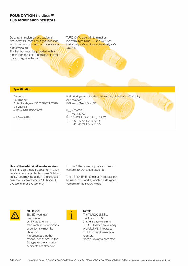
140 /0407 Hans Turck GmbH & Co.KG • D–45466 Mülheim/Ruhr • Tel. 0208/4952-0 • Fax 0208/4952-264 • E-Mail: [email protected] • Internet: www.turck.com
Data transmission on bus cables is frequently infl uenced by signal refl ection, which can occur when the bus ends are not terminated. The fi eldbus must be provided with a termination resistor at both ends in order to avoid signal refl ection.
Use of the intrinsically-safe versionThe intrinsically-safe fi eldbus termination resistors feature protection class “intrinsic safety” and may be used in the explosion hazardous area category 1 G (zone 0), 2 G (zone 1) or 3 G (zone 2).
CAUTION The EC type test examination certifi cate and the manufacturer’s declaration of conformity must be observed. It is essential that the “special conditions” in the EU type test examination certifi cate are observed.
NOTE The TURCK JBBS... junctions to IP67 (4 and 6 channels) and JRBS... to IP20 are already provided with integrated switch-in bus termination resistors. Special versions excepted.
In zone 0 the power supply circuit must conform to protection class “ia”.
The RS-49-TR-Ex termination resistor can be used in networks, which are designed conform to the FISCO model.
TURCK offers plug-in termination resistors, type M12 × 1 and 7/8“, for intrinsically safe and non-intrinsically safe circuits.
Specifi cation Connector PUR housing material and contact carriers, oil resistant, 300 V rating Coupling nut stainless steel Protection degree (IEC 60529/EN 60529) IP67 and NEMA 1, 3, 4, 6P Max. ratings – RSV49-TR, RSEV49-TR Umax = 50 VDC Ta = -40...+80 °C – RSV-49-TR-Ex Ui = 25 VDC, Ii = 250 mA, Pi =1.2 W Ta = -40...70 °C (EEx ia IIC T4) -40...40 °C (EEx ia IIC T6)
FOUNDATION fi eldbus™Bus termination resistors
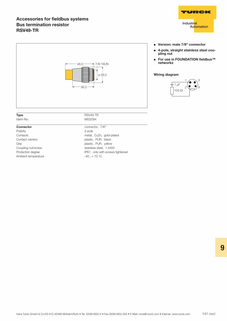
Hans Turck GmbH & Co.KG • D–45466 Mülheim/Ruhr • Tel. 0208/4952-0 • Fax 0208/4952-264 • E-Mail: [email protected] • Internet: www.turck.com 141 /0407
9
ñ Edition:
Hans Turck GmbH & Co.KG ñ D-45472 Mülheim an der Ruhr ñ Witzlebenstraße 7 ñ Tel. 0208 4952-0 ñ Fax 0208 4952-264 ñ [email protected] ñ www.turck.com
Accessories for fieldbus systemsBus termination resistorRSV49-TR
� Version: male 7/8" connector
� 4-pole, straight stainless steel cou-pling nut
� For use in FOUNDATION fieldbus™ networks
Wiring diagram
�����
�����
�
�
�
Type RSV49-TRIdent-No. 6602094
Connector connector, 7/8''Polarity 2-poleContacts metal, CuZn, gold-platedContact carriers plastic, PUR, blackGrip plastic, PUR, yellowCoupling nut/screw stainless steel, 1.4404Protection degree IP67, only with screws tightenedAmbient temperature -40...+ 70 °C
����
����
���� �
������
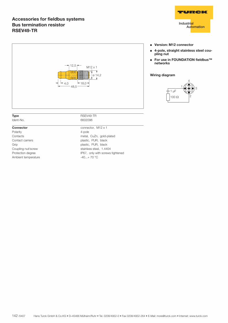
142 /0407 Hans Turck GmbH & Co.KG • D–45466 Mülheim/Ruhr • Tel. 0208/4952-0 • Fax 0208/4952-264 • E-Mail: [email protected] • Internet: www.turck.com
ñ Edition:
Hans Turck GmbH & Co.KG ñ D-45472 Mülheim an der Ruhr ñ Witzlebenstraße 7 ñ Tel. 0208 4952-0 ñ Fax 0208 4952-264 ñ [email protected] ñ www.turck.com
Accessories for fieldbus systemsBus termination resistorRSEV49-TR
� Version: M12 connector
� 4-pole, straight stainless steel cou-pling nut
� For use in FOUNDATION fieldbus™ networks
Wiring diagram
�
�
�
���
���
Type RSEV49-TRIdent-No. 6602096
Connector connector, M12 x 1Polarity 4-poleContacts metal, CuZn, gold-platedContact carriers plastic, PUR, blackGrip plastic, PUR, blackCoupling nut/screw stainless steel, 1.4404Protection degree IP67, only with screws tightenedAmbient temperature -40...+ 70 °C
���� �������
����
���
�����
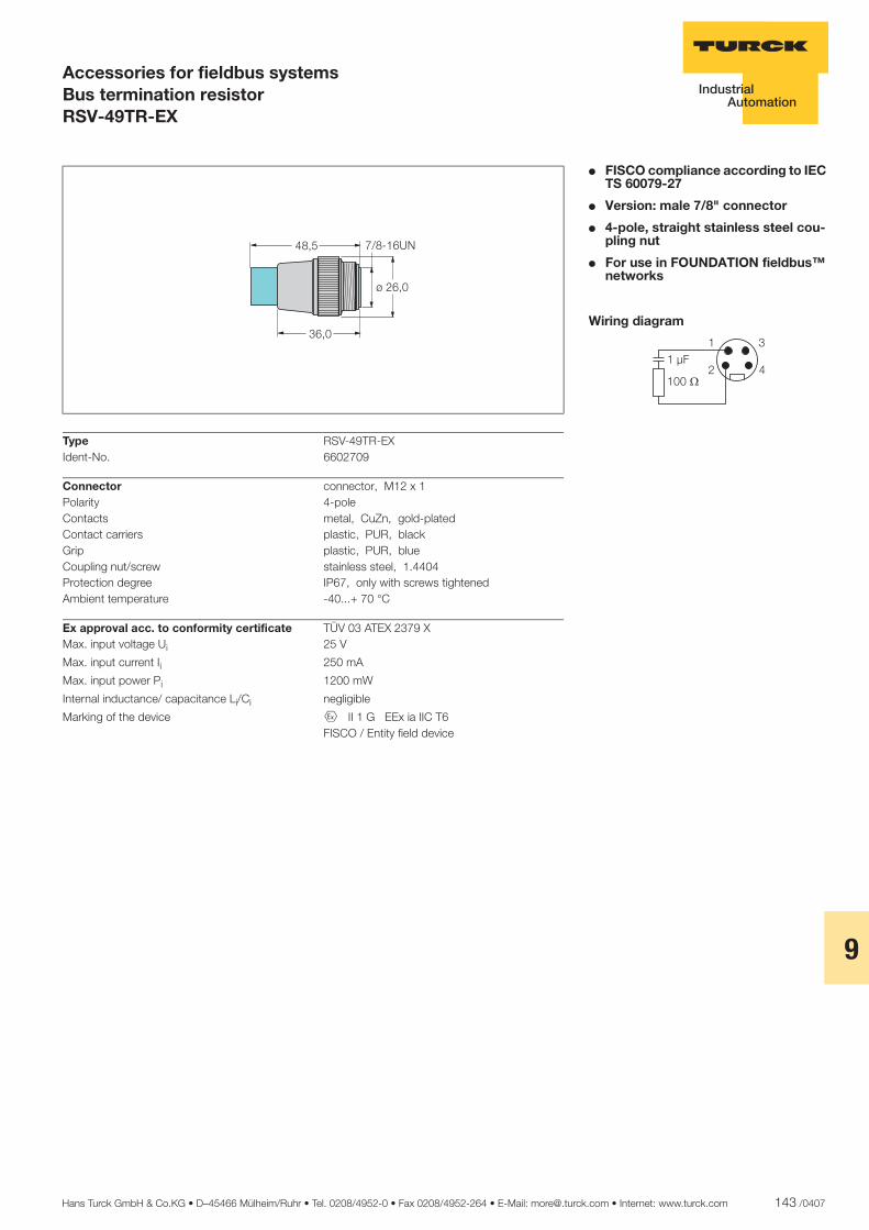
Hans Turck GmbH & Co.KG • D–45466 Mülheim/Ruhr • Tel. 0208/4952-0 • Fax 0208/4952-264 • E-Mail: [email protected] • Internet: www.turck.com 143 /0407
9
ñ Edition:
Hans Turck GmbH & Co.KG ñ D-45472 Mülheim an der Ruhr ñ Witzlebenstraße 7 ñ Tel. 0208 4952-0 ñ Fax 0208 4952-264 ñ [email protected] ñ www.turck.com
Accessories for fieldbus systemsBus termination resistorRSV-49TR-EX
� FISCO compliance according to IEC TS 60079-27
� Version: male 7/8" connector
� 4-pole, straight stainless steel cou-pling nut
� For use in FOUNDATION fieldbus™ networks
Wiring diagram
�����
�����
�
�
Type RSV-49TR-EXIdent-No. 6602709
Connector connector, M12 x 1Polarity 4-poleContacts metal, CuZn, gold-platedContact carriers plastic, PUR, blackGrip plastic, PUR, blueCoupling nut/screw stainless steel, 1.4404Protection degree IP67, only with screws tightenedAmbient temperature -40...+ 70 °C
Ex approval acc. to conformity certificate TÜV 03 ATEX 2379 XMax. input voltage Ui 25 V
Max. input current Ii 250 mA
Max. input power Pi 1200 mW
Internal inductance/ capacitance Li/Ci negligible
Marking of the device É II 1 G EEx ia IIC T6 FISCO / Entity field device
����
����
���� �
������
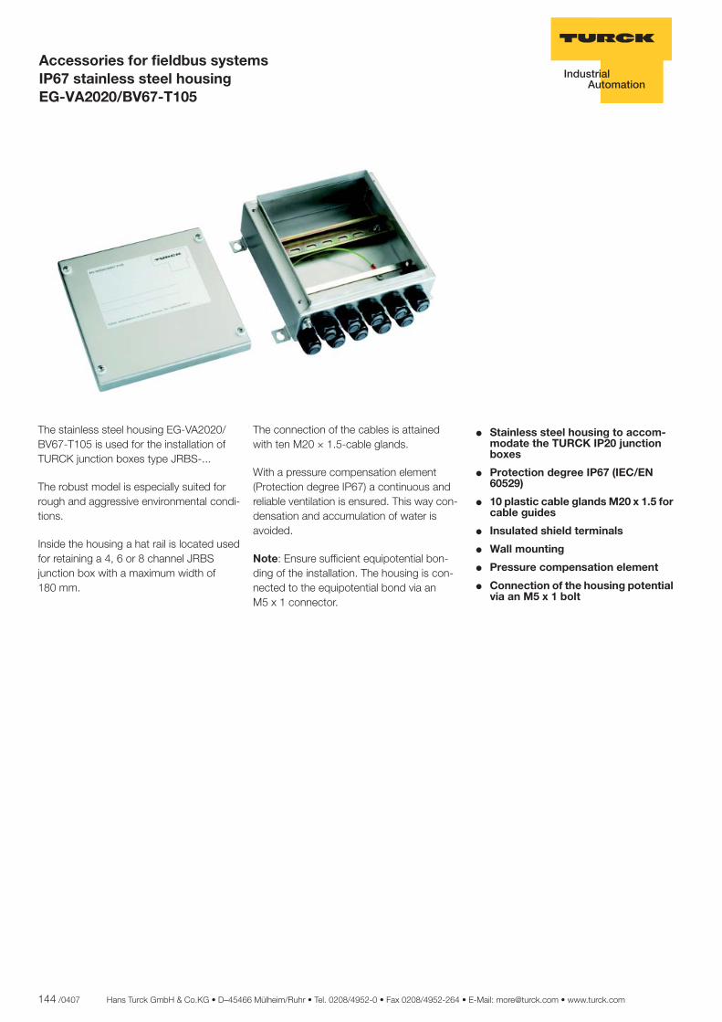
144 /0407 Hans Turck GmbH & Co.KG • D–45466 Mülheim/Ruhr • Tel. 0208/4952-0 • Fax 0208/4952-264 • E-Mail: [email protected] • www.turck.com
ñ Edition:
Hans Turck GmbH & Co.KG ñ D-45472 Mülheim an der Ruhr ñ Witzlebenstraße 7 ñ Tel. 0208 4952-0 ñ Fax 0208 4952-264 ñ [email protected] ñ www.turck.com
Accessories for fieldbus systems IP67 stainless steel housing EG-VA2020/BV67-T105
� Stainless steel housing to accom-modate the TURCK IP20 junction boxes
� Protection degree IP67 (IEC/EN 60529)
� 10 plastic cable glands M20 x 1.5 for cable guides
� Insulated shield terminals
� Wall mounting
� Pressure compensation element
� Connection of the housing potential via an M5 x 1 bolt
The stainless steel housing EG-VA2020/BV67-T105 is used for the installation of TURCK junction boxes type JRBS-...
The robust model is especially suited for rough and aggressive environmental condi-tions.
Inside the housing a hat rail is located used for retaining a 4, 6 or 8 channel JRBS junction box with a maximum width of 180 mm.
The connection of the cables is attained with ten M20 × 1.5-cable glands.
With a pressure compensation element (Protection degree IP67) a continuous and reliable ventilation is ensured. This way con-densation and accumulation of water is avoided.
Note: Ensure sufficient equipotential bon-ding of the installation. The housing is con-nected to the equipotential bond via an M5 x 1 connector.

Hans Turck GmbH & Co.KG • D–45466 Mülheim/Ruhr • Tel. 0208/4952-0 • Fax 0208/4952-264 • E-Mail: [email protected] • www.turck.com 145 /0407
10
ñ Edition:
Hans Turck GmbH & Co.KG ñ D-45472 Mülheim an der Ruhr ñ Witzlebenstraße 7 ñ Tel. 0208 4952-0 ñ Fax 0208 4952-264 ñ [email protected] ñ www.turck.com
Accessories for fieldbus systems IP67 stainless steel housing EG-VA2020/BV67-T105
Dimensions
������
������
�����
��� ���
Type EG-VA2020/BV67-T105 Ident-No. 6884135
Connection cable glands 10 x M20 x 1.5 (Ø 6...13 mm); plastic, black Earthing bolt M5 x 1
Protection degree IP67 Ambient temperature -30...+80 °C Relative humidity 95 %, non condensing Housing material stainless steel 1.430/AISI304 Wall thickness 1.5 mm Housing surface grinded and polished (240 grain size distribu-
tion) Housing colour silver Material sealing PUR Dimensions 200 x 200 x 80.5 mm Connection mode wall mounting
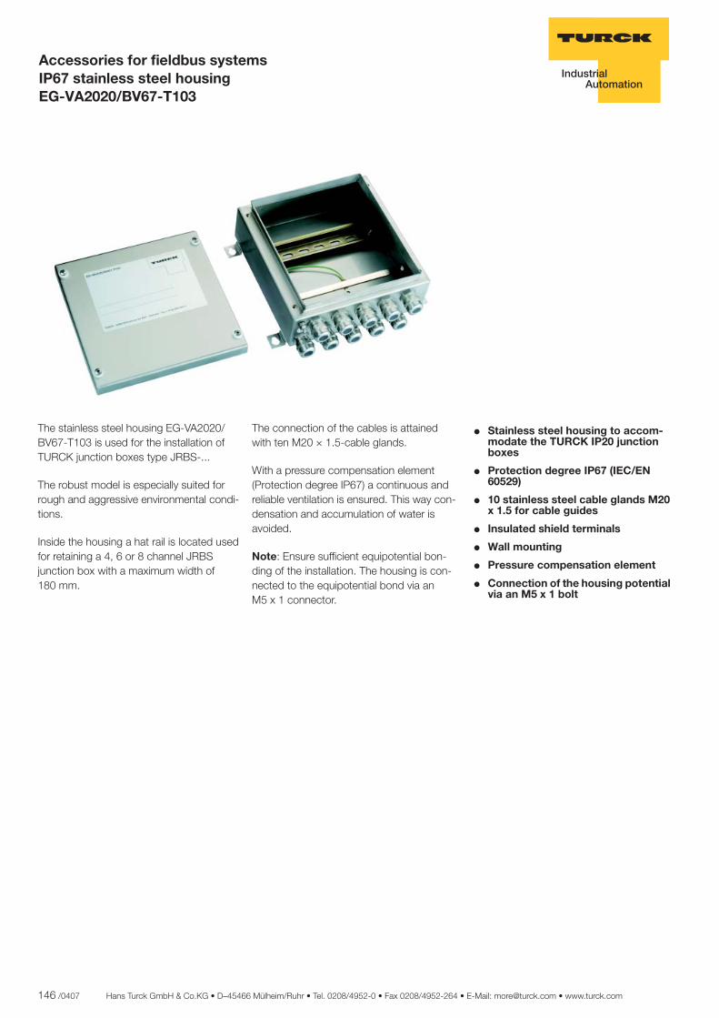
146 /0407 Hans Turck GmbH & Co.KG • D–45466 Mülheim/Ruhr • Tel. 0208/4952-0 • Fax 0208/4952-264 • E-Mail: [email protected] • www.turck.com
ñ Edition:
Hans Turck GmbH & Co.KG ñ D-45472 Mülheim an der Ruhr ñ Witzlebenstraße 7 ñ Tel. 0208 4952-0 ñ Fax 0208 4952-264 ñ [email protected] ñ www.turck.com
Accessories for fieldbus systems IP67 stainless steel housing EG-VA2020/BV67-T103
� Stainless steel housing to accom-modate the TURCK IP20 junction boxes
� Protection degree IP67 (IEC/EN 60529)
� 10 stainless steel cable glands M20 x 1.5 for cable guides
� Insulated shield terminals
� Wall mounting
� Pressure compensation element
� Connection of the housing potential via an M5 x 1 bolt
The stainless steel housing EG-VA2020/BV67-T103 is used for the installation of TURCK junction boxes type JRBS-...
The robust model is especially suited for rough and aggressive environmental condi-tions.
Inside the housing a hat rail is located used for retaining a 4, 6 or 8 channel JRBS junction box with a maximum width of 180 mm.
The connection of the cables is attained with ten M20 × 1.5-cable glands.
With a pressure compensation element (Protection degree IP67) a continuous and reliable ventilation is ensured. This way con-densation and accumulation of water is avoided.
Note: Ensure sufficient equipotential bon-ding of the installation. The housing is con-nected to the equipotential bond via an M5 x 1 connector.
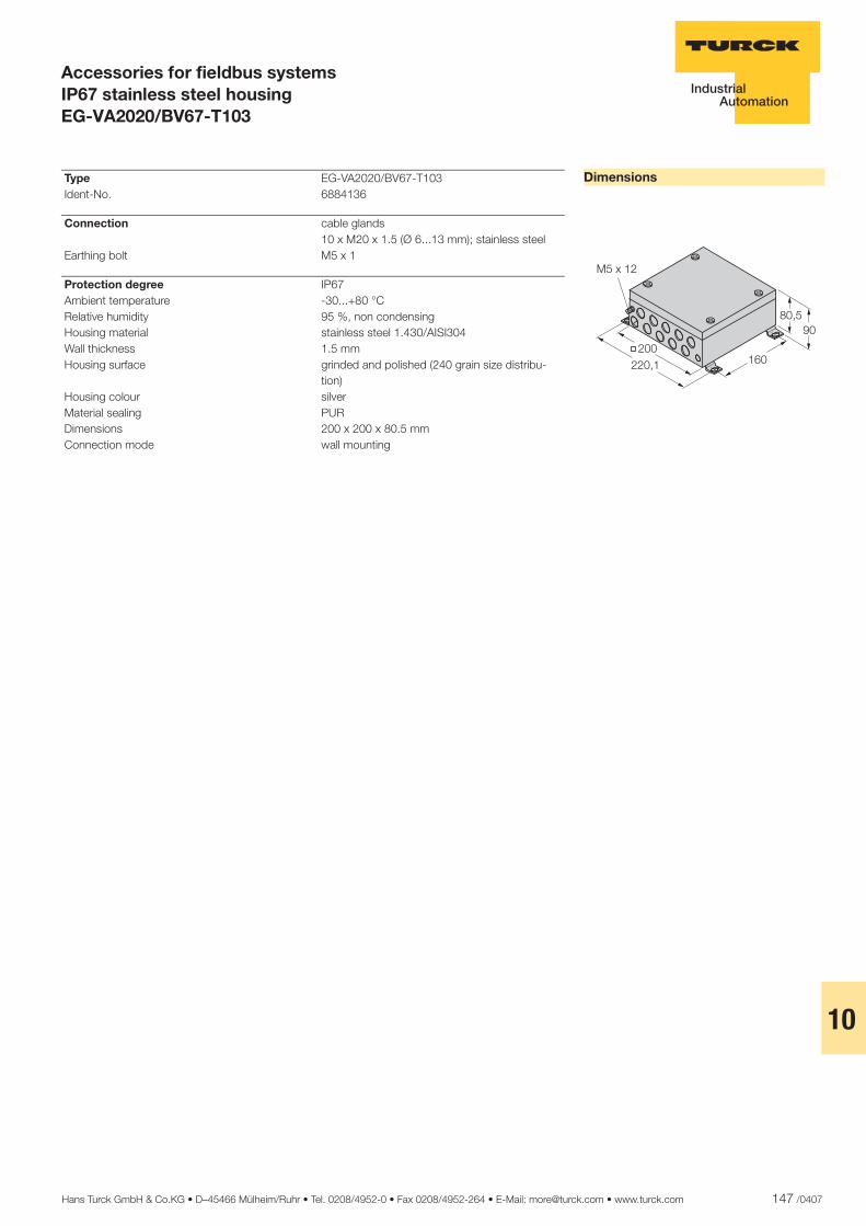
Hans Turck GmbH & Co.KG • D–45466 Mülheim/Ruhr • Tel. 0208/4952-0 • Fax 0208/4952-264 • E-Mail: [email protected] • www.turck.com 147 /0407
10
ñ Edition:
Hans Turck GmbH & Co.KG ñ D-45472 Mülheim an der Ruhr ñ Witzlebenstraße 7 ñ Tel. 0208 4952-0 ñ Fax 0208 4952-264 ñ [email protected] ñ www.turck.com
Accessories for fieldbus systems IP67 stainless steel housing EG-VA2020/BV67-T103
Dimensions
�� ��
������
�����
� �����
Type EG-VA2020/BV67-T103 Ident-No. 6884136
Connection cable glands 10 x M20 x 1.5 (Ø 6...13 mm); stainless steel Earthing bolt M5 x 1
Protection degree IP67 Ambient temperature -30...+80 °C Relative humidity 95 %, non condensing Housing material stainless steel 1.430/AISI304 Wall thickness 1.5 mm Housing surface grinded and polished (240 grain size distribu-
tion) Housing colour silver Material sealing PUR Dimensions 200 x 200 x 80.5 mm Connection mode wall mounting
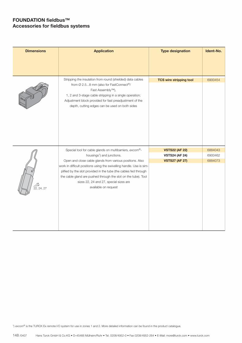
148 /0407 Hans Turck GmbH & Co.KG • D–45466 Mülheim/Ruhr • Tel. 0208/4952-0 • Fax 0208/4952-264 • E-Mail: [email protected] • www.turck.com
Stripping the insulation from round (shielded) data cables
from Ø 2.5...8 mm (also for FastConnect®/
Fast Assembly™),
1, 2 and 3-stage cable stripping in a single operation;
Adjustment block provided for fast preadjustment of the
depth, cutting edges can be used on both sides
TCS wire stripping tool 6900454
Special tool for cable glands on multibarriers, excom®-
housings1) and junctions.
Open and close cable glands from various positions. Also
work in diffi cult positions using the swivelling handle. Use is sim-
plifi ed by the slot provided in the tube (the cables fed through
the cable gland are pushed through the slot on the tube). Tool
sizes 22, 24 and 27, special sizes are
available on request
VSTS22 (AF 22)
VSTS24 (AF 24)
VSTS27 (AF 27)
6884043
6900462
6884073
Dimensions Ident-No.Application Type designation
����������
1) excom® is the TURCK Ex remote I/O system for use in zones 1 and 2. More detailed information can be found in the product catalogue.
FOUNDATION fi eldbus™Accessories for fi eldbus systems
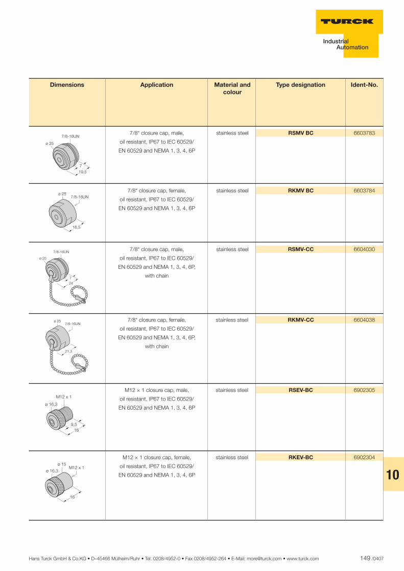
Hans Turck GmbH & Co.KG • D–45466 Mülheim/Ruhr • Tel. 0208/4952-0 • Fax 0208/4952-264 • E-Mail: [email protected] • www.turck.com 149 /0407
10
���
����� ����
����� �
���
����
7/8“ closure cap, male,
oil resistant, IP67 to IEC 60529/
EN 60529 and NEMA 1, 3, 4, 6P
stainless steel RSMV BC 6603783
7/8“ closure cap, female,
oil resistant, IP67 to IEC 60529/
EN 60529 and NEMA 1, 3, 4, 6P
stainless steel RKMV BC 6603784
7/8“ closure cap, male,
oil resistant, IP67 to IEC 60529/
EN 60529 and NEMA 1, 3, 4, 6P,
with chain
stainless steel RSMV-CC 6604030
7/8“ closure cap, female,
oil resistant, IP67 to IEC 60529/
EN 60529 and NEMA 1, 3, 4, 6P,
with chain
stainless steel RKMV-CC 6604038
Dimensions Ident-No.Material and colour
Application Type designation
����� �
���
���
����
����� ����
M12 × 1 closure cap, male,
oil resistant, IP67 to IEC 60529/
EN 60529 and NEMA 1, 3, 4, 6P
stainless steel RSEV-BC 6902305
��
�������
������
��
M12 × 1 closure cap, female,
oil resistant, IP67 to IEC 60529/
EN 60529 and NEMA 1, 3, 4, 6P
stainless steel RKEV-BC 6902304
��
�������������
���
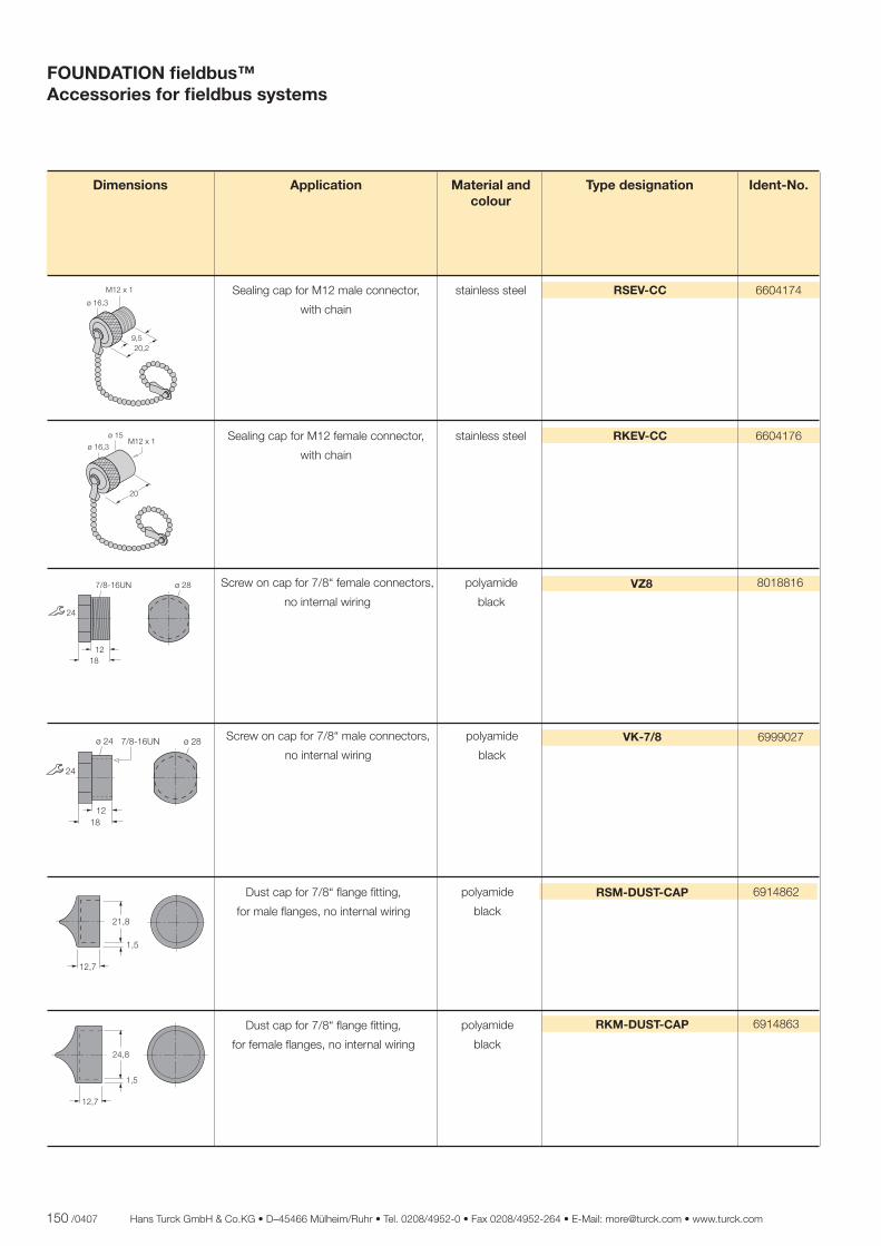
150 /0407 Hans Turck GmbH & Co.KG • D–45466 Mülheim/Ruhr • Tel. 0208/4952-0 • Fax 0208/4952-264 • E-Mail: [email protected] • www.turck.com
����� � ����
���
����
����
Sealing cap for M12 male connector,
with chain
stainless steel RSEV-CC 6604174
Sealing cap for M12 female connector,
with chain
stainless steel RKEV-CC 6604176
Dimensions Ident-No.Material and colour
Application Type designation
FOUNDATION fi eldbus™Accessories for fi eldbus systems
����
�������
������
��
��
�������������
���
Screw on cap for 7/8“ male connectors,
no internal wiring
polyamide
black
VK-7/8 6999027
����
���
����
Dust cap for 7/8“ fl ange fi tting,
for male fl anges, no internal wiring
polyamide
black
6914862RSM-DUST-CAP
Dust cap for 7/8“ fl ange fi tting,
for female fl anges, no internal wiring
polyamide
black
6914863RKM-DUST-CAP
Screw on cap for 7/8“ female connectors,
no internal wiring
polyamide
black
VZ8 8018816����� � ����
���
����
���
����
����
Hans Turck GmbH & Co.KG • D–45466 Mülheim/Ruhr • Tel. 0208/4952-0 • Fax 0208/4952-264 • E-Mail: [email protected] • www.turck.com 151 /0407
10
���� �����
�������
����
������
M12 × 1 closure cap, male,
oil resistant, IP54 to IEC 60529/
EN 60529 and NEMA 1, 3, 4, 6P
PUR
yellow
VS-M12 6999003
M12 × 1 closure cap, female,
oil resistant, IP54 to IEC 60529/
EN 60529 and NEMA 1, 3, 4, 6P
PUR
yellow
VK-M12 6999025
Dimensions Ident-No.Material and colour
Application Type designation
ø 16
149
M12 x 1
ø 16
14
M12 x 1
M12 × 1 closure cap, male
oil resistant, IP67 to IEC 60529/
EN 60529 and NEMA 1, 3, 4, 6P
stainless steel/PUR
grey
RSEV49-CC 6603489
152 /0407 Hans Turck GmbH & Co.KG • D–45466 Mülheim/Ruhr • Tel. 0208/4952-0 • Fax 0208/4952-264 • E-Mail: [email protected] • www.turck.com
FOUNDATION fi eldbus™Accessories for fi eldbus systems
7/8“ feed-through receptacles, male/fe-
male, IP67 to IEC 60529/EN 60529 and
NEMA 1, 3, 4, 6, stainless steel
1 × 7/8“ ( F015 )
1 × 7/8“ ( F016 )
RSFV-RKFV49/22 6602357
M12 × 1 feed-through receptacles, male/
female, IP67 to IEC 60529/EN 60529 and
NEMA 1, 3, 4, 6, stainless steel
1 × M12 ( F040 )
1 × M12 ( F041 )
FKV-FSV49/M12 6603678
Dimensions Ident-No.Application Type designationConnection technology
Fig. ( Fxxx )
( F015 ) ( F016 )
1 = –2 = +3 = shield4 = earth
Pin assignmentw
1 = –2 = +3 = shield4 = earth
v w
1 = –2 = +3 = shield4 = earth
v
1 = –2 = +3 = shield4 = earth
( F040 ) ( F041 )
�
�
�
�
�
�
�
�
�
� �
�
�
� �
�
� ������
��������
���������������
������� !"�!��#�$�$���!�
� "������� !"
�������%����
������� !"%&���
'�"#�$
����� ��
�����
�����
Hans Turck GmbH & Co.KG • D–45466 Mülheim/Ruhr • Tel. 0208/4952-0 • Fax 0208/4952-264 • E-Mail: [email protected] • www.turck.com 153 /0407
10
154 /0407 Hans Turck GmbH & Co.KG • D–45466 Mülheim/Ruhr • Tel. 0208/4952-0 • Fax 0208/4952-264 • E-Mail: [email protected] • www.turck.com
Type designation Page Type designation Page Type designation Page
Type index
BKV8140-0/9 135BKV8240-0/9 137BS4149-0/9 130BSV4149-0/16 134BSV4149-0/9 132BSV8140-0/9 136BSV8240-0/9 138BV4149-0/16 133BV4149-0/9 131Cable 492A…M 112Cable 492BA…M 112Cable FB4910-BK...M 113Cable FBA-YE/SD…M 111Cable FBH-YE/SD...M 110Cable FBY-BK/LD…M 109Cable FBY-.../SD…M 108DPC-49-ADU 14DPC-49-HSEFD/24VDC 16DPC-49-IPS 12DPC-49-MB-RC 10EG-VA2020/BV67-T103 146EG-VA2020/BV67-T105 144FD-49-T317/Ex 34FKV49 125FKV49-0,3M/14,5/C1117 127FKV49-0,3M/M20/C1117 129FKV-FSV49/M12 152FSV49 124FSV49-0,3M/14,5/C1117 126FSV49-0,3M/M20/C1117 128JBBS-49-E413/3G 70JBBS-49-E413/Ex 82JBBS-49-E613/3G 72JBBS-49-E613/Ex 84JBBS-49-M413/3G 74JBBS-49-M413/Ex 86JBBS-49-M613/3G 76JBBS-49-M613/Ex 88JBBS-49SC-E413/3G 46JBBS-49SC-E413/Ex 58JBBS-49SC-E613/3G 48JBBS-49SC-E613/Ex 60JBBS-49SC-M413/3G 50JBBS-49SC-M413/Ex 62JBBS-49SC-M613/3G 52JBBS-49SC-M613/Ex 64JBBS-49SC-T415/3G 42JBBS-49SC-T415B/Ex 54JBBS-49SC-T615/3G 44JBBS-49SC-T615B/Ex 56JBBS-49-T415/3G 66JBBS-49-T415B/Ex 78JBBS-49-T615/3G 68JBBS-49-T615B/Ex 80JRBS-40-12C/Ex 104JRBS-40-4C/Ex 98JRBS-40-6C/Ex 100JRBS-40-8C/Ex 102JRBS-40SC-12C/Ex 96
JRBS-40SC-4C/Ex 90JRBS-40SC-6C/Ex 92JRBS-40SC-8C/Ex 94KMU-40Ex/1GD 38KMU-40Ex/3G 37MBD49-T415/Ex 32PSU-3214 20RKCV-FBY49x-*M/5D 115RKCV-RKCV-FBY49x-*M/5D 115RKEV-BC 149RKEV-CC 150RKFV49 119RKFV49-0,3M/14,5 121RKFV49-0,3M/M20 123RKM-DUST-CAP 150RKMV BC 149RKMV-CC 149RKV492A-*M 116RKV492BA-*M 116RKV-FBY49x-*M/5D 115RKV-RKV-FBY49x-*M/5D 115RPC49-10120Ex 22RPC49-10180/3G 26RPC49-10265Ex 24RPC49-10320/3G 28RPC49-205 18RSCV-FBY49x-*M/5D 115RSCV-RKCV-FBY49x-*M/5D 115RSCV-RSCV-FBY49x-*M/5D 115RSEV49-CC 151RSEV49-TR 142RSEV-BC 149RSEV-CC 150RSFV49 118RSFV49-0,3M/14,5/C1117 120RSFV49-0,3M/M20/C1117 122RSFV-RKFV49/22 152RSM-DUST-CAP 150RSMV BC 149RSMV-CC 149RSV492A-*M 116RSV492BA-*M 116RSV49-TR 141RSV-49TR-Ex 143RSV-FBY49x-*M/5D 115RSV-RKV492A-*M 116RSV-RKV492BA-*M 116RSV-RKV-FBY49x-*M/5D 115RSV-RSV-FBY49x-*M/5D 115TCS wire stripping tool 148VK-7/8 150VK-M12 151VS-M12 151VSTS22 148VSTS24 148VSTS27 148VZ8 150WKCV-FBY49x-*M/5D 115WKCV-WKCV-FBY49x-*M/5D 115
WKV-FBY49x-*M/5D 115WKV-WKV-FBY49x-*M/5D 115WSCV-FBY49x-*M/5D 115WSCV-WKCV-FBY49x-*M/5D 115WSCV-WSCV-FBY49x-*M/5D 115WSV-FBY49x-*M/5D 115WSV-WKV-FBY49x-*M/5D 115WSV-WSV-FBY49x-*M/5D 115
Hans Turck GmbH & Co.KG • D–45466 Mülheim/Ruhr • Tel. 0208/4952-0 • Fax 0208/4952-264 • E-Mail: [email protected] • www.turck.com 155 /0407
10
11
D301024 0407
*D301024ßß0407*... and more than 60 representatives and agencies world-wide. Subject to change without notice
BELGIUM Multiprox N. V. P. B. 71 Lion d’Orweg 12 9300 Aalst Tel. +32 53 766566 Fax +32 53 783977 E-Mail [email protected]
CROATIA Tipteh Zagreb d.o.o. Pešæanska 170 1000 Zagreb Tel. +3 85 1 3816574 Fax +3 85 1 3816577 E-Mail [email protected]
CZECH REPUBLIC TURCK s.r.o. Hradecká 1151 500 03 Hradec Králové 3 Tel. +420 49 5518-766 Fax +420 49 5518-767 E-Mail [email protected]
PR OF CHINA TURCK (Tianjin) Sensor Co. Ltd. 18,4th Xinghuazhi Road, Xiqing Economic Development Area, 300381 Tianjin Tel. +86 22 83988-188 83988-199 Fax +86 22 83988-111 E-Mail [email protected]
FRANCE TURCK BANNER S.A.S 3, Rue de Courtalin Magny-Le-Hongre 77703 Marne-La-Vallee Cedex 4 Tel. +33 1 6043-6070 Fax +33 1 6043-1018 E-Mail [email protected]
GREAT BRITAIN TURCK BANNER LIMITED Blenheim House Hurricane Way Wickford, Essex SS11 8YT Tel. +44 1268 578888 Fax +44 1268 763648 E-Mail [email protected]
HUNGARY TURCK Hungary kft. Könyves Kalman Krt.76 1087 Budapest Tel. +36 1 4770-740 Fax +36 1 4770-741 E-Mail [email protected]
India International Convention Centre, A-603/604, 6th Floor, ICC Trade Towers, Senapati Bapat Road, Pune - 411016, Maharashtra - India Tel. + 91 20 25630039 25630040 Fax + 91 20 25630039 E-Mail [email protected]
ITALY TURCK BANNER S. R. L. Via Adamello, 9 20010 Bareggio (MI) Tel. +39 02 90364-291 Fax +39 02 90364-838 E-Mail [email protected]
JAPAN Turck Japan Offi ce #202 MBD Bldg. 2F, 3-3-23, Minami-Aoyama, Minato-ku, 107-0062, Tokyo, Japan Tel. + 81 3 57722820 Fax + 81 3 34082571 E-Mail [email protected]
KOREA TURCK Korea Co. Ltd. Room No 406, Gyeonggi Technopark 1271-11, Sa 1-Dong, Sangnok-Gu, Ansan-city, Gyeonggi-Do, Korea Tel. +82 31 5004-555 Fax +82 31 5004-558 E-Mail [email protected]
MACEDONIA Tipteh d.o.o. Skopje Ul. Jani Lukrovski br. 2/33 1000 Skopje Tel. +389 70 399474 Fax +389 23 174197 E-Mail [email protected]
MEXICO TURCK Mexico S. DE R.L. DE C.V. Carr. Saltillo-Zacatecas km 4.5 s/n Parque Industrial “La Angostura“ Saltillo, COAH. 25070 Tel. +52 844 4826-924 Fax +52 844 4826-926 E-Mail [email protected]
THE NETHERLANDS TURCK B. V. Postbus 297 8000 AG Zwolle Tel. +31 38 4227-750 Fax +31 38 4227-451 E-Mail [email protected]
POLAND TURCK sp.z o.o ul. Kepska 2 45-129 Opole Tel. +48 77 4434-800 Fax +48 77 4434-801 E-Mail [email protected]
ROMANIA TURCK Automation Romania SRL Str. luliu Tetrat nr. 18 Sector 1 011914 Bukarest Tel. +40 21 2300279 2300594 Fax +40 21 2314087 E-Mail: [email protected]
RUSSIA TURCK Rus O.O.O. Altufyevskoe shosse, 1/7 127106 Moskau Tel. +7 495 2342661 Fax +7 495 2342665 E-Mail [email protected]
SINGAPORE TURCK Singapore Pte. Ltd. 25 International Business Park #03-22/23 German Centre 609916 Singapore Tel. +65 65628716 Fax +65 65628719 E-Mail [email protected]
USA TURCK Inc. 3000 Campus Drive Minneapolis, MN 55441-2656 Tel. +1 763 553-9224 553-7300 Fax +1 763 553-0708 E-Mail [email protected]
TURCK WORLD-WIDE HEADQUARTERS
GERMANY Hans Turck GmbH & Co. KG Witzlebenstraße 7 45472 Mülheim an der Ruhr P. O. Box 45466 Mülheim an der Ruhr Tel. +49 208 4952-0 Fax +49 208 4952-264 E-Mail [email protected]
www.turck.com