Embed Size (px)
Citation preview

�
What Is a Light Guide?A light guide is a device designed to transport light from a light source to a point at some distance with minimal loss. Light is transmitted through a light guide by means of total internal reflection. Light guides are usually made of optical grade materials such as acrylic resin, polycarbonate, epoxies, and glass. A light guide can be used to transmit light from an LED lamp on a pc board to a front panel for use as status indication, can be used to collect and direct light to backlight an LCD display or legend, and can be used as the means to illuminate a grid pattern on a see through window. This Application Brief discusses the basics of simple light guide design for these and other possible uses.
Basic PrinciplesSnell’s Law: When light rays are incident to a boundary between two mediums, i.e. plastic and air, the light rays are refracted when they cross the boundary as illustrated in Figure �. The angle at which the light rays are incident to the boundary is called the angle of incidence, φi, and the angle at which the light rays leave the boundary is called the angle of refraction, φf,. Snell’s law states: the index of refraction of the first medium, ni, multiplied by the sine of the angle of incidence at the boundary, φi, is equal to the index of refraction of the second medium, nr, multiplied by the sine of the angle of refraction at the boundary, φf.
Specular ReflectionSpecular reflection is defined when the angle of incidence equals the angle of reflection as shown in Figure 2. Specular reflected light rays are reflected without loss. Fresnel Loss: When light rays cross the boundary from one medium to another, there is a loss due to reflection at the boundary as shown in Figure 2. This is called Fresnel loss and is calculated with the following expression:
(2)
Figure 1. Refracted Light Ray.
When light rays cross a boundary into a more dense medium, the angle φf is less than the angle φi. Conversely, when light rays cross a boundary into a less dense medium, the angle φf is greater than the angle φi. This is illustrated in Figure 3 for light rays passing through a parallel plastic (glass) plate. The light rays are incident
to the plate top surface at an angle φi, are refracted within the plate at the angle φf, are incident to the plate bottom surface of the plate at the angle φ'i, and then are refracted in the air at the angle φ'f. The angle of refraction within the plastic plate φf is smaller than the angle of refraction in
For plastic to air and glass to air interface boundaries, the Fresnel loss is 4%.
fi
ff
ni
nr
INCIDENCEMEDIUM
MEDIABOUNDARY
REFRACTIONMEDIUM
REFRACTEDLIGHT RAY
INCIDENTLIGHT RAY
Snell’s Law = ni sinfi = nf sinff ����(1)
1.50 - 1.001.50 + 1.00Fresnel Loss = 100•
2
�= 4%
ni – nf ni + nf Fresnel Loss = 100 •
2
for plastic (glass) to air interfaces.
Light Guide Techniques Using LED Lamps
Application Brief I-003

2
air φ'f since the plastic is a more dense medium than air. The exit rays are parallel to the incident rays because the internal angle of refraction φf and the internal angle of incidence φ'i are equal, and because the external angle of incidence φi and the external angle of refraction φ'f are equal.
Total Internal ReflectionWhen the angle of refraction is 90° the incident light ray is refracted along the boundary, as shown in Figure 4. The sin φf (90°) = �.0, and Equation � for Snell’s law reduces to: ni sin φi = nf. This expression can be rewritten to define the critical incident angle for total internal reflection, φc:
Critical Angle Definition:
sin fc = (3)
Setting nf = �.0 in Equation 3, the index of refraction value for air, the critical angle for a light guide can be quickly determined when the material index of refraction is known. For most plastics and glass, the index of refraction is approximately �.50. Thus, the critical angle for total internal reflection for most light guide materials is approximately 42°. Internal specular reflection within a light guide at the guide surface to air boundary is utilized to help transmit light through the light guide.
φc = 42° approximate value for plastics and glass.
Figure 2. Specular Reflected Light Ray at Mirror Smooth Boundary.
Light rays internal to a light guide incident to guide surface to air boundary are total internally reflected when the angle of incidence is 42° or greater. Having the critical angle being slightly less than 45° for most light guide materials is very convenient because it allows the use of 45° reflecting prism surfaces in light guide designs.
φi φr
φf
ni
nr
INCIDENCEMEDIUM
SMOOTH SPECULARREFLECTINGBOUNDARY
REFRACTEDLIGHT RAY
INCIDENTLIGHT RAY
SPECULARREFLECTEDLIGHT RAY
REFLECTION MEDIUMMORE DENSE THANINCIDENCE MEDIUM
φi = φrφf < φi
Figure 3. Light Ray Passing Through Nondiffused Plastic (Glass) Parallel Plate.
Figure 4. Definition of Critical Angle for Total Internal Reflection.
φi
φi'
φr
φr'
φf
φf'
AIR
AIR
φi = φr = 4% FRESNEL LOSSφi' = φr' = 4% FRESNEL LOSSφf = φi'φi = φf' =� EXIT RAY OFFSET AND� PARALLEL TO INCIDENT RAY
INCIDENT RAY
NON-DIFFUSEDPLASTIC (GLASS)PLATE
SPECULAR REFLECTINGSMOOTH SURFACE
SPECULAR REFLECTINGSMOOTH SURFACE
EXIT RAY = 92%OF INCIDENT RAY
φc = CRITICAL ANGLEφi < φc FOR EXIT LIGHT RAYφi' > φc FOR TOTAL INTERNAL REFLECTION
φf
φcφi'
φi
φf = 90
LIGHT RAY REFRACTEDALONG BOUNDARY
TOTAL INTERNALLYREFLECTED LIGHT RAY
INCIDENT LIGHT RAYS
EXIT LIGHT RAY
nf ni
nf
ni
sin φc = = 0.667,�.50

3
Ray TracingRay tracing is a technique used to predict the path of light rays into, through, and out of a light guide. The principles of Snell’s law, Fresnel loss, and specular reflection are applied at each guide surface to air interface to determine the direction of the light ray. Ray tracing is used in this Application Brief to illustrate the performance of light guide designs.Light Guide DesignThere are three design issues to be examined when designing a light guide: �) effective flux coupling to get the light from an LED
lamp into the light guide with minimal loss, 2) transmitting the light through the guide to the exit
surface, and 3) allowing the light to escape through the exit surface
with minimal loss.
Flux Coupling to Get LED Light into a Light GuideFlux from an LED lamp must be effectively coupled to the entrance end of a light guide to permit light capture (light to enter the light guide) with minimal loss before it can be effectively transmitted and utilized. Flux coupling and capture are usually ineffective when the LED lamp is external to the envelope of the light guide surface to air boundary, and conversely are effective when the lamp is located inside the light guide surface to air boundary.
With the LED lamp external to the light guide, as shown in Figure 5, effective flux coupling and light capture occur only when the LED lamp radiation pattern angle matches the acceptance pattern angle of the light guide. Thus, effective flux coupling may be very difficult to accomplish and most of the flux from the LED lamp may be lost. Less than �0% of the available flux is typically captured by a light guide with this configuration.
Figure 5. LED Lamp External to Light Guide.
Figure 6. Using a Lens to Focus LED Light Onto Light Guide.
LOST FLUX
LOST FLUX
LIGHT GUIDE
LESS THAN 10% FLUX CAPTURE
LED LAMP
θe θa
LIGHT GUIDE
UP TO 80% FLUX CAPTUREFLUX FOCUSING LENS
LED LAMPθe
f f

4
A lens may be used for flux coupling to focus the flux from an LED lamp onto the entrance end of a light guide, as shown in Figure 6. The focused flux should just fill the entrance end of the light guide. Light capture can be up to 80% effective, but does require availability of physical distance to accommodate the focal length of the lens. The cost of the focusing lens must be added to the cost of the light pipe design.
The best design for most effective flux coupling is to have the LED lamp located inside the envelope of the light guide surface to air boundary. This concept is illustrated in Figure 7a. In this configuration, the LED lamp is embedded into the light guide and all light rays emanating from the LED lamp are captured by the light guide. The light capture effectiveness is 92%, taking into account the Fresnel losses across the air gap. This design concept is recommended for use with dome LED package devices such as T-� 3/4, T-�, and subminiature LED lamps. When the LED lamp package is glued into the light guide with an optical grade epoxy, as shown in Figure 7b, the epoxy package of the lamp optically disappears due to the elimination of Fresnel losses, and the flux capture is essentially �00%. In most light guide appli-cations, using epoxy to glue the LED lamp to the light guide to eliminate air gap Fresnel loss is neither practical nor necessary. All of the suggested light guide designs presented in this Application Brief assume there is an air gap between the LED lamp and the light guide.
Figure 7a. LED Lamp Located Inside a Light Guide for Best Flux Coupling.
Figure 7b. LED Lamp Epoxied into a Light Guide to Eliminate Fresnel Loss.
Physical Attributes of a Light GuideThe exterior surface finishes of a light guide are important to assure proper operation, as shown in Figure 8. The sides parallel to the direction of light travel should be smooth, like a mirror, to affect total internal reflection. They may be painted with a white light reflecting paint to reflect those diagonal rays less than the critical angle that may otherwise escape. The entrance end should be smooth, contoured to match the LED lamp device for effective light capture, allowing light rays to enter the light guide with minimal reflection and scatter. The exit end should be diffused. A diffused exit end has random critical angles across its surface providing a high probability light rays can escape, and also scatters the light rays producing a wide radiation pattern.
Light guides may be made in any desired shape, cylindrical (oval), rectangular (square), conical (increasing in size from entrance end to exit end), or any special shape (arrow, star shaped, quarter moon, etc.). For rectangular and special shapes, the corners should have a radius greater than 0.5 mm (0.020 in.), not sharp, to assure illumination in the corners. The shape of the light guide may gradually change along its length, i.e. from circular at the entrance end to accommodate the lamp, to square at the exit end, as shown in Figure 8.
Light Entrance End of Light Guides for Various Types of LED DevicesFor effective flux coupling and light capture, the light entrance end of a light guide should be smooth and flat or concave contoured to match the light output radiation pattern and package configuration of the mating LED lamp device.
For SMT LED lamp devices that have a light emitting area that is a flat surface, the entrance end of the light guide
Figure 8. The Basic Attributes of a Light Guide, shown with a change in shape from Circular to Rectangular along its Length.
LIGHT GUIDE
8% FRESNEL LOSSIN AIR GAP
92% FLUX CAPTURE
LED LAMP
LIGHT GUIDE
LED EMITTER EPOXIED INTOLIGHT GUIDE TO ELIMINATE AIR GAP = NO FRESNEL LOSS
100% FLUX CAPTURE
LED LAMP
SMOOTH FLAT OR CONCAVECONTOURED SURFACE TOMATCH LED LAMP
LIGHT GUIDE
DIFFUSED EXITSURFACE
ROUNDED CORNERS0.5 mm (0.020 IN.)MINIMUM RADIUS
SMOOTH (MIRROR)EXTERIOR SURFACE
OPTIONAL WHITE LIGHTREFLECTING PAINT
ON EXTERIOR SURFACE

5
Figure 9. Light Guide with a Smooth Flat Entrance End positioned over an SMT LED Lamp.
Figure 10. A Light Guide with a Smooth Concave Entrance End increases Flux Coupling and Light Capture from an SMT Chip LED Lamp.
should be a smooth flat surface. The entrance end of the light guide should be placed over and in close proximity to the light emitting surface of the SMT LED lamp for effective flux coupling and light capture, as illustrated in Figure 9. The entrance end of the light guide needs to be slightly larger than the emitting surface of the LED lamp to assure 92% flux capture, taking into account the Fresnel losses across the air gap.
SMT Chip LED lamp packages are cubic in shape, diffused, allowing light to emit from the sides as well as the top. Only about 40% of the total available flux is emitted from the top. The other 60% is emitted from the side. Thus, only 40% of the light from an SMT Chip LED lamp would be captured by a light guide with a flat surface entrance end, the remaining flux is lost. A light guide with a smooth concave entrance end to fit over the SMT Chip LED lamp is effective in increasing flux capture, as shown in Figure �0. The smooth concave surface enhances flux coupling and light capture by reducing the possibility of a light ray intersecting the light guide at the critical angle and being reflected. With the concave entrance end, about 70% to 80% of the available emitted flux from an SMT Chip LED is captured by the light guide, and the light loss is reduced to 20% to 30%.
This concave contoured entrance end technique may be used with any light guide/LED lamp combination to enhance flux coupling and light capture. In Figure ��, a “Yoke” lead SMT subminiature lamp is used to illuminate a light guide located at the back side of a pc board. The lamp is located in a through hole and surface mounted on the component side of the board. The smooth concave surface entrance end of the light guide captures more of the radiated flux from the LED lamp than does a flat surface.
As a minimum insertion distance for positive flux coupling and light capture, standard T-� 3/4 untinted, nondiffused
Figure 11. The Concave End of a Light Guide Enhances Flux Coupling and Light Capture From an Inverted Surface Mounted “Yoke” Lead SMT Subminiature LED Lamp.
SMT CHIP LED
PC BOARD
SMOOTH, CONCAVESURFACE INCREASES
FLUX CAPTURE
LIGHT GUIDE
20%-30% LOST FLUX
62%-72% FLUX CAPTURE
CONCAVE SMOOTHSURFACE ENHANCES
FLUX CAPTURE
“YOKE” LEAD SMTSUBMINIATURE LED LAMP
PC BOARD
LIGHT GUIDE
LIGHT GUIDE
SMT LED LAMP
PC BOARD
SMOOTH, FLATSURFACE
ENTRANCEEND

6
LED lamps should be inserted into the entrance end of a light guide up to the LED reflector cup, located within the lamp package, as shown in Figure �2. This assures 92% flux capture, taking into account the Fresnel loss across the air gap between the lamp dome and light guide. For best performance, insertion to the base flange on the lamp package is recommended. For T-� 3/4 LED lamps, the lamp acceptance hole should be 5.33 mm (0.2�0 in.) to 5.59 mm (0.220 in.) in diameter. The end of the hole should be a smooth spherical dome radius. The hole should be at least 5.33
mm (0.2�0 in.) in depth for minimum length insertion, and 8.3� mm (0.327 in.) minimum in depth for full length insertion. For T-� LED lamps, the lamp acceptance hole diameter should be 3.30 mm (0.�30 in.) to 3.43 mm (0.�35
Figure 12. Insertion of T-1 3/4 and T-1 Untinted, Nondiffused LED Lampsinto the Entrance End of a Light Guide for Effective Flux Coupling.
in.) in diameter. Only full length insertion to the lamp base flange is recommended for T-� lamps to achieve effective flux coupling and capture, with a minimum hole depth of 2.�65 mm (0.085 in.).
LED light bars may also be used as light sources for light guides. These devices that have a light emitting area that is a large flat surface. Therefore, for effective flux coupling and light capture the entrance end of the light guide should be a smooth flat surface, placed over and in close proximity to the light emitting surface of
the LED light bar, as illustrated in Figure �3. The entrance end of the light guide needs to be slightly larger than the emitting surface of the light bar to assure 92% flux capture, taking into account the Fresnel losses across the air gap.
Diffused Exit End of a Light GuideA diffused exit end presents random critical angles to internal light rays, assuring the probability of light escaping from a light guide. This may also be viewed as the diffused exit end having random indices of refraction. The exiting light rays are disbursed at random angles into a wide radiation pattern of light, as shown in Figure �4.
Light Guides Around CornersLight guides may be bent to go around corners. The bend radius should be equal to or greater than two thicknesses or twice the diameter of the light guide to minimize light loss. The light ray reflections follow the smooth contour of the radius bend without loss, as shown in Figure �5. Sharp right angle direction changes may be achieved by using a Figure 13. Light Guide with a Smooth Flat Entrance End Positioned Over an LED Light
Bar for Best Flux Coupling.
LIGHT GUIDELIGHT GUIDE
92% FLUX CAPTURE
SMOOTH INTERIORSURFACE FOR LED
LAMP AT ENTRANCE END
T-1 3/4, T-1 LED LAMPT-1 3/4 LED LAMP
RECOMMENDED INSERTIONOF LAMP TO FLANGE ATBASE OF LAMP PACKAGE
MINIMUM INSERTIONFOR T-1 3/4 LAMP TOLED REFLECTOR CUP
PC BOARD
92% FLUX CAPTURE
LIGHT GUIDE
SMOOTH, FLATSURFACE
ENTRANCE END
LEDLIGHT BAR

7
Figure 14. Diffused Exit End Enhances the Probability of Light Escaping from a Light Guide.
Figure 15. Light Guide with a 90° Bend. Light Rays are Scattered by Diffused Exit End.
Figure 16. Light Guide with Built in 45° Prism Reflector.
DIAMETER OR THICKNESS
LED LAMP
LIGHT GUIDE
LIGHT RAYREFLECTIONSFOLLOWCURVATURE OFLIGHT GUIDE
MINIMUM BEND RADIUS =2X DIAMETER OR THICKNESS
LIGHT GUIDE
SMT LED LAMP
PC BOARD
45 REFLECTIVEPRISM SURFACE
LIGHT GUIDE
LIGHT RAYS ARE DISBURSEDINTO A WIDE RADIATIONPATTERN
LED LAMPDIFFUSED EXIT SURFACEENHANCES THE PROBABILITYOF LIGHT RAYS ESCAPING

8
reflective prism design in the light guide at the 90° bend location, as shown in Figure �6.
Wedge Light GuidesWedge shaped light guides may be used to achieve backlighting effects. Two basic kinds are shown in Figure �7, the planar surface wedge which gives a uniform distribution of light and the curved surface wedge which gives a light distribution somewhat logarithmic in nature. The planar surface wedge is typically used to backlight transreflective LCD displays.
Backlighting Transreflective LCD Displays Transreflective LCD displays may be backlighted with LED lamps using either a simple flat planar light guide or a wedge light guide. For small area LCD displays, � to 2 inches high by 2 to 4 inches wide, a simple flat planar light guide may be used, as shown in Figure �8. The top surface of the light guide is diffused to permit light to escape. The edges and backside are smooth. The back surface is coated with white light reflecting paint. Two surface mount pc board assemblies are mounted to the sides of the transparent plate for even illumination. Optional grooves are cut into the plate to provide alignment of the pc board assembly with the plate. The number of SMT LED lamps,
spaced on �/4 to �/2 inch centers, depends upon the size of the transparent plate and the required illumination.
A planar wedge light guide may be used with SMT LED lamps for backlighting a medium size transreflective LCD display, i.e. 2 to 3 inches high by 3 to 6 inches wide. A diffusing film interlayer between the LCD and the wedge guide may be used to diffuse the light, as shown in Figure �9. The SMT LED lamps are spaced on �/4 to �/2 inch spacing to achieve even illumination. The SMT LED lamps are electrically connected in series on the pc board assembly.
A right angle planar wedge light guide may be used with SMT LED lamps to backlight a medium sized transreflective LCD display that is mounted parallel to a surface mount pc board assembly, as shown in Figure 20a. The SMT LED lamps are spaced on �/4 to �/2 inch spacing to achieve even illumination. The SMT LED lamps are electrically connected in series on the pc board assembly. The ray tracing is shown in Figure 20b.
Untinted, nondiffused T-� 3/4 or T-� LED lamps can also be used with a right angle planar wedge light guide as shown in Figure 2�. The spacing for these lamps is between adjacent placement and 3/4 inches centers, depending upon the desired luminance.
A dual right angle planar wedge light guide may be used with SMT LED lamps to backlight a medium-large size transreflective LCD display, 4 to 6 inches high by 6 to 9 inches wide, that is mounted parallel to a surface mount
Figure 18. A Transreflective LCD Display Backlighted with SMT LED Lamps,Surface Mounted on Small PC Boards, Using a Simple Flat Planar Light Guide.
Figure 17. Wedge Light Guides, Planar Surface and Curved Surface.
SMT LED LAMP
WHITE REFLECTING PAINT OVERSPECULAR REFLECTING SURFACE
PLANAR SURFACEWEDGE GUIDE
CURVED SURFACEWEDGE GUIDE
PC BOARD
TRANSREFLECTIVE LCD
DIFFUSED SURFACE
SURFACEMOUNT
PC BOARDASSEMBLY
ALIGNMENT GROOVEBOTH SIDES
2.29 mm(0.090 IN.)
SMT LEDLAMP
WHITE PAINT
CROSS SECTIONAL END VIEW SHOWING RAY TRACING

9
pc board assembly, as shown in Figure 22. The SMT LED lamps are spaced on �/4 to �/2 inch centers for both light pipe wedges to achieve even illumination. This technique also provides sufficient illumination for bright ambient lighting conditions. The SMT LED lamps are electrically connected in series-parallel on the pc board assembly, one series string for each side of the light guide.
Diffusing FilmsDiffusing films are made with particles that internally reflect incident light rays so that exit light rays are scattered at random angles, as illustrated in Figure 23. Diffusing films are lossy as some of the incidant flux, Ev(0)(lm/m2), is reflected and some of the flux is absorbed. The remaining flux exits the diffusing film over a wide radiation pattern that can be described by three parameters: �) Iv(0)(cd), the luminous intensity perpendicular to the
Figure 19. A Planar Wedge Light Guide used with SMT LED Lamps for Backlighting a Medium Size Transreflective LCD Display.
Figure 20a. A Right Angle Planar Wedge Light Guide used with SMT LED Lamps for Backlighting a Medium Size Transreflective LCD Display.
Figure 20b. Ray Tracing Pattern for A Right Angle Planar Wedge Light Guide usedfor Backlighting a Medium Size Transreflective LCD Display.
SURFACE MOUNTPC BOARD ASSEMBLY
WHITE REFLECTING PAINTON BACKSIDE SURFACE
PLANAR TRIANGULARLIGHT GUIDE
LCD DISPLAYMODULE
DIFFUSINGFILM
SMT LED LAMP
LCD DISPLAYMODULE
RIGHT ANGLEPLANAR WEDGELIGHT GUIDEDIFFUSING FILM
SURFACE MOUNTPC BOARDASSEMBLY
SMT LED LAMPWHITE REFLECTINGPAINT ON BACKSIDE SURFACE
LCD DISPLAY MODULE
RIGHT ANGLEPLANAR WEDGE
GUIDE
DIFFUSING FILMWHITE LIGHT
REFLECTING PAINT
SMT LED LAMPCROSS SECTION SHOWING RAY TRACING

�0
surface of the film, 2) θ �/2 , the off-axis angle where the luminous intensity
is �/2 the on-axis value, and 3) Lv(0)(cd/m2), the surface luminance.
A diffusing film with a Lambertian radiation pattern has a θ �/2 value of 60 degrees, and is the maximum viewing angle performance that can be achieved with a diffuser.
Figures of merit for comparing one diffusing film with another are:
• Lv(0)(cd/m2)/Ev(0)(lm/m2) = The ratio of on-axis lumi-nance to incidant flux.
Where: Lv(0)(cd/m2) = Iv(0)(cd)/A(m2), and A(m2) = a selected area of the diffusing film surface.
• 2θ �/2 = The viewing cone angle. Using these figure of merit parameters, a trade-off between output luminance and radiation pattern must then be made in selecting a diffusing film in order to achieve desired overall illumination performance in combination with a light guide. The higher the value of the Lv(0)/Ev(0) ratio, the brighter is the output luminance through the diffusing film for illuminating an LCD display. Also, the wider is the 2θ �/2 angle, the better will be the output radiation pattern (viewing cone angle) from the diffusing film, reducing the chance of an LCD display appearing brighter in the center than at the outer edges. The following companies supply diffusing films:
Optical Systems 3M Safety and Security Systems Division, 3M Center, Building 225-4N-�4
St. Paul, MN 55�44-�0000
�-(800)-328-7098 Products:
Diffusion Films: Type �00, 5 mils, 2q �/2 = 26°.
Type 070, �0 mils, 2q �/2 = 32°.
Type 050, �6 mils, 2q �/2 = 36°. Type 040, 20 mils, 2q �/2 = 40°
Brightness Enhancement Film (BEF)
Miles, Inc.
Figure 21. A T-1 3/4 or T-1 Untinted, Nondiffused LED lamp Used as the Light Source for a Right Angle Planar Wedge Light Guide.
Figure 22. A Dual Right Angle Planar Wedge Light Guide used with SMT LED Lamps for Backlighting a Medium-Large Size Transreflective LCD Display.
Figure 23. Properties and Figures of Merit of a Diffusing Film.
RIGHT ANGLEPLANAR WEDGE
GUIDE
DIFFUSING FILMWHITE LIGHT
REFLECTING PAINT
LCD DISPLAY MODULE
T-1 3/4 OR T-1 LED LAMP
Iv (0) LIGHT OUTPUTRADIATION PATTERN
Iv (θ 1/2)
2θ 1/2
2θ 1/2
θ 1/2
DIFFUSING FILM
Ev(0): INCIDENT FLUX
FIGURES OF MERIT:Lv(0)Ev(0)
LCD DISPLAYMODULE
DUAL RIGHT ANGLEPLANAR WEDGE
LIGHT GUIDE
SURFACE MOUNTPC BOARDASSEMBLY
SMT LED LAMP
WHITE REFLECTINGPAINT ON SIDE
SURFACESWHITE REFLECTINGPAINT ON BACKSIDE
SURFACE
DIFFUSING FILM

��
Polymers Division
Mobay Road, Bldg. 8
Pittsburgh, PA �5205-974�
(4�2) 777-2000 FAX: (4�2) 777-202�
Products:
Makrofol BL 6-2:a pigment filled polycarbonate film, 8 and �6 mil thick-nesses, 2θ �/2 = �8° and 36°.Makrofol LT 6-4: a glass fiber filled polycarbonate film, �6 to 20 mil thicknesses, 2θ �/2 = �6°.
Physical Optics Corporation 20600 Gramercy Place Bldg. �00
Torrance, CA 9050�
(3�0) 320-3088 Fax: (3�0) 320-8067
Products: Beam Homogenizing Light Shaping Diffusing Films.
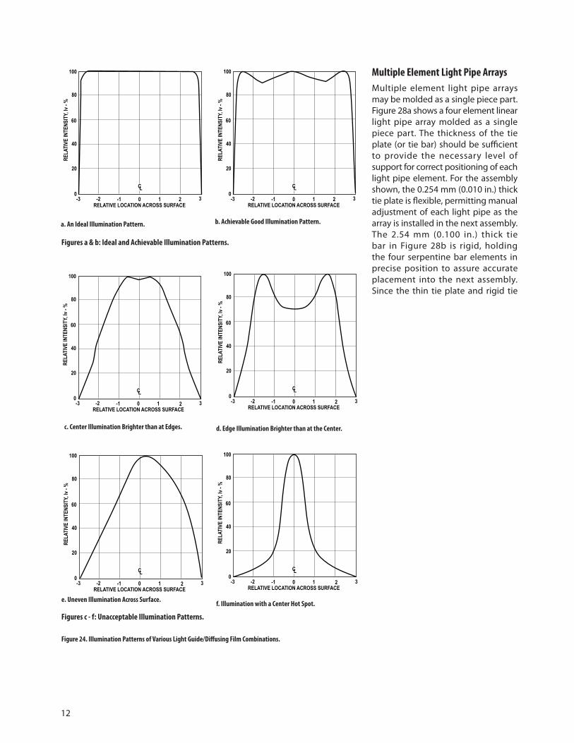
Illumination Patterns Luminous intensity variations, as measured across the exit surface of a light guide or a light guide/diffusing film combination, determine the evenness of illumination. The ideal would be to have a perfect rectangularly shaped illumination pattern so that the luminous intensity is the same at all points across the surface, the edges, the corners, and the center all be at the same luminance. An approximation to this ideal is shown in Figure 24a, where the illumination is flat across the surface, falling off smoothly at the edges. However, in a good design there are typically minor luminous intensity variations across the surface as shown in Figure 24b. These variations should not exceed 20% of the luminous intensity at the center.
Figures 24c - 24f show various luminous intensity patterns that produce unacceptable illumination variations across the face of an LCD display and should be avoided. Careful optical design of the light guide and selection of the proper diffusing film to reduce luminous intensity variations should produce an acceptable illumination pattern equivalent to Figure 24a or 24b.
Backlighting Flat Surface Annunciator Panels Made with a Diffusing FilmFlat plate light guides, wedge light guides, and right angle and dual right angle wedge light guides, with either SMT LED or standard T-� 3/4 and T-� LED lamps, are ideal for illuminating flat surface annunciator panels. The techniques shown in Figures �8 through 24 directly apply to annunciators that are the same size as the
LCD modules. Typically, annunciators are made by silk-screening opaque letters and symbols on the surface of a diffusing film, leaving open a background area for illumination. The most effective approach is to silk-screen the message on the backside surface so it cannot be damaged. The diffusing film is placed directly onto the light emitting surface of the light guide to form the annunciator unit. In the “off” condition, the background surrounding the message is dark and without color. When illuminated, the bright color of the LED light readily signifies to an observer the “on” condition of the annunciator. The opaque letters and symbols forming the message are easy to read against the illuminated background.
These same concepts may be applied to making small sized annunciators utilizing the light pipes described in the following section. In many cases, silk-screening an opaque background, leaving open letters or a symbol, is most effective. The silk-screened diffusing film is glued to the exit surface of the light pipe with an optically clear adhesive to form the annunciator module. In the “off” condition, the letters or symbol are dark and without color and tend to blend with the background. In the “on” condition, the bright letters or symbol, with the color of the LED light, stand out vividly contrasting in appearance against the background.
Simple Shaped Light Pipes for Front Panel IndicationLight guides for front panel indication are typically called “light pipes.” Light pipes can be made in many simple and compound shapes. Simple cylindrical, rectangular, and triangular shaped light pipes are illustrated in Figure 25, utilizing an SMT LED as the light source. These simple light pipes can be made from commercially available plastic rod.
Custom Shaped Light Pipes for Front Panel IndicationCustom shapes, usually precision molded, are designed to achieve special effects, as illustrated in Figure 26. Two or more LED light sources may be needed to illuminate a large arrow shaped light pipe. A “three legged” light pipe may be used to give a three condition status in a single indicator, red for “danger”, yellow for “caution”, and green for “safe”.
Compound Shaped Light Pipes for Front Panel IndicationCompound light pipe configurations may also be precision molded for specialized applications. The serpentine light pipe, shown in Figure 27, is designed to move light around an obstruction. The light ray reflections follow the curvature of the light pipe without loss.
�2
a. An Ideal Illumination Pattern. b. Achievable Good Illumination Pattern.
Multiple Element Light Pipe Arrays Multiple element light pipe arrays may be molded as a single piece part. Figure 28a shows a four element linear light pipe array molded as a single piece part. The thickness of the tie plate (or tie bar) should be sufficient to provide the necessary level of support for correct positioning of each light pipe element. For the assembly shown, the 0.254 mm (0.0�0 in.) thick tie plate is flexible, permitting manual adjustment of each light pipe as the array is installed in the next assembly. The 2.54 mm (0.�00 in.) thick tie bar in Figure 28b is rigid, holding the four serpentine bar elements in precise position to assure accurate placement into the next assembly. Since the thin tie plate and rigid tie
Figures a & b: Ideal and Achievable Illumination Patterns.
c. Center Illumination Brighter than at Edges. d. Edge Illumination Brighter than at the Center.
e. Uneven Illumination Across Surface. f. Illumination with a Center Hot Spot.
Figures c - f: Unacceptable Illumination Patterns.
Figure 24. Illumination Patterns of Various Light Guide/Diffusing Film Combinations.
100
80
60
40
20
0-3 -2 -1 0 1 2 3
RELATIVE LOCATION ACROSS SURFACE
RELA
TIVE
INTE
NSIT
Y, Iv
- %
CL
100
80
60
40
20
0-3 -2 -1 0 1 2 3
RELATIVE LOCATION ACROSS SURFACE
RELA
TIVE
INTE
NSIT
Y, Iv
- %
CL
100
80
60
40
20
0-3 -2 -1 0 1 2 3
RELATIVE LOCATION ACROSS SURFACE
RELA
TIVE
INTE
NSIT
Y, Iv
- %
CL
100
80
60
40
20
0-3 -2 -1 0 1 2 3
RELATIVE LOCATION ACROSS SURFACE
RELA
TIVE
INTE
NSIT
Y, Iv
- %
CL
100
80
60
40
20
0-3 -2 -1 0 1 2 3
RELATIVE LOCATION ACROSS SURFACE
RELA
TIVE
INTE
NSIT
Y, Iv
- %
CL
100
80
60
40
20
0-3 -2 -1 0 1 2 3
RELATIVE LOCATION ACROSS SURFACE
RELA
TIVE
INTE
NSIT
Y, Iv
- %
CL

�3
Figure 25. Simple Light Pipe Shapes for Use as Front Panel Indicators Using an SMT LED as the Light Source.
bar are perpendicular to the light pipes, cross coupling of scattered light from an illuminated light pipe element is minimal, and will not illuminate adjacent light pipe elements.
Tinted, Diffused vs. Untinted, Nondiffused LED Lamps as Emitters for Light Pipes In most cases, untinted, nondiffused LED lamps with semi-wide flux radiation patterns of 24 degrees, or larger, are preferred emitters for light guides and light pipes. However, there are designs where a tinted, diffused LED lamp with a wide radiation pattern of 45 to 60 degrees is the preferred emitter. This concept is illustrated in Figure 29. The semi-wide radiation pattern of a T-� 3/4 untinted, nondiffused LED lamp fits the requirements of a long “slim” light pipe. However, a short “stocky” light pipe requires an LED lamp with a wide flux radiation pattern to prevent a “hot spotty” appearance at the exit end that may be caused by using a lamp with a narrower radiation pattern.
Molded, Flexible, Diffused, Light Pipe ArraysFlexible, diffused, light pipe arrays are very effective in backlighting keypads and indicator windows in front panel assemblies. Flexible light pipe arrays are usually molded from an untinted, diffused, optical grade silicone rubber, such as �50-OU, supplied by Tory Rubber Company, a division of Dow Corning. As illustrated in Figure 30a, the individual light pipe elements are short in length, are either solid or hollow inside, and vary in size and shape. The SMT LED lamps fit up against the bases of solid light pipe elements, or fit inside hollow light pipe elements, as illustrated in Figure 30b. The light pipe array is placed over an SMT LED lamp pc board assembly to form a backlighting unit, as illustrated in Figure 30b. A bright, wide angle illumination pattern is achieved at the exit end of each light pipe element. A pc board assembly with standard T-� 3/4 or T-� LED lamps may also be used, with the lamps fitting inside the hollow elements of the flexible light pipe array. The backlighting unit is then mated with the keypad and front cover to form the illuminated front panel assembly. The push button caps in the keypad are molded from untinted, nondiffused acrylic or polycarbonate. The indicator windows in the front cover are untinted and usually nondiffused. Both the key caps and windows may be diffused if desired. The wide illumination pattern from each diffused light pipe element assures an even illumination and wide viewing angle for each push button cap and front panel indicator window. In some panel designs, the indicator windows are cut-outs in the front panel cover, allowing solid light
Figure 26. Custom Shaped Light Pipes for Use as Front Panel Indicators.
Figure 27. A Serpentine, Rectangular Light Pipe Designed to Move Light Around an Obstruction.
SMT LEDs USED AS THE LIGHT SOURCEFOR THESE SIMPLE LIGHT PIPES
TWO SMT LEDsSAME COLOR RED YELLOW GREEN
THREE DIFFERENT COLOR SMT LEDs
PC BOARD
SMTLED LAMP
LIGHT RAYREFLECTIONSFOLLOWCURVATURE OFLIGHT PIPE
COMPOUND CURVERECTANGULARLIGHT PIPE
DIFFUSEDEXIT END

�4
pipe elements to protrude about 2.54 mm (0.�00 in.). This makes a pleasing design, adding some depth to a front panel configuration.
The following company designs and molds flexible diffused light pipe arrays for backlighting keypads and indicator windows in front panel assemblies. Diffused silicone rubber �50-OU is the material used.
Keytek
44 Old State Road #3
New Milford, CT 06776
(203) 350-��53
FAX: (203) 350-��55
Light Pipe Output Radiation Patterns The light output radiation pattern from the exit end of a light pipe should be designed to meet the luminance and v iewing angle requirements in a defined ambient lighting environment. A trade-off is made between on-axis intensity and radiation pattern, as illustrated in Figure 3�. A wide radiation pattern, at the expense of on axis intensity, Iv (0), is better for a wide off-axis viewing angle. This is suitable for most applications in moderate ambient lighting conditions less than �000 fc. For bright ambient light conditions, such as for outdoor viewing, radiation pattern is reduced to achieve a high on-axis intensity.
A designer may measure the light output radiation pattern from the exit end of a light pipe using a goniometer. The goniometer rotating detector should be at a nominal distance of 305 mm (�2 in.) from the exit end of the light guide. Radiation pattern (viewing angle) curves are obtained, similar to those shown in Figure 32.
Figure 28a. A Four Element Light Pipe Linear Array, Molded as a Single Piece Part with a Flexible Tie Plate.
Figure 28b A Four Element Serpentine Light Pipe Linear Array, Molded as a Single Piece Part with a Rigid Tie Bar.
Figure 29. Conceptual Use of Tinted, Diffused and Untinted, Nondiffused LED Lamps as Emitters in Different Light Pipe Configurations.
LIGHT PIPE ELEMENTS
TIE BAR
2.54 mm(0.100 IN.)
LIGHT PIPEELEMENT
ELEMENTTIE PLATE
0.254 mm(0.010 IN.)
LONG, “SLIM”LIGHT PIPE
T-1 3/4 UNTINTEDNONDIFFUSED
LED LAMPT-1 3/4 TINTED
DIFFUSEDLED LAMP
SHORT,“STOCKY”
LIGHT PIPE

�5
Edge Lighting a Transparent Flat Plate with Grid Lines A flat transparent plate with engraved or etched grid lines on the face surface may be edge lighted with LED lamps, as shown in Figure 33a. The face surfaces of a transparent flat plate are smooth for an observer to see through. The surfaces of the grid lines are rough to give the necessary diffusing surface. The grid lines may be coated with a thin layer of white translucent paint to enhance daylight readability, with some loss in grid illumination. All four edges of the light plate may be painted with white reflecting paint.
Light within the light plate is internally reflected by all surfaces, and escapes only through the diffused lines providing the grid line illumination, as shown in Figure 33b. Holes are drilled into two opposite ends to accept the domes of HLMP-650X subminiature lamps. The LED lamps are epoxied to the transparent plate and electrically wired in series. The rectangular bases of the LED lamps are not inserted into the light plate in order to keep the plate thickness at 2.54 mm (0.�00 in.). The number of LED lamps required, spaced on approximately �/4 to �/2 inch centers, is determined by the size of the light plate and the desired luminance of the grid lines.
A transparent plate with engraved or etched grid lines may also be edge lighted using surface mounted SMT LED lamps as shown in Figure 34. Two surface mount pc board assemblies are mounted to the sides of the transparent plate for even illumination of the grid lines. Optional grooves are cut into the plate to provide alignment of the pc board assembly with the plate. The number of SMT LED lamps, spaced on �/4 to �/2 inch centers, depends upon the size of the transparent plate and the required illumination of the grid lines. Advantages of this approach are:
�) the minimum thickness of the transparent plate, typically 2.29 mm (0.090 in.) with optional grooves to enclose the SMT LED lamps, or 2.03 mm (0.080 in.) without grooves for minimal plate thickness, and
2) the LED lamps are not epoxied to the transparent plate.
Figure 30a. A Molded, Flexible, Silicone Rubber, Untinted, Diffused Light Pipe Array used in Combination with an SMT LED PC Board.
Figure 30b. The Flexible, Diffused Light Pipe Array and SMT LED PC Board Form a Backlighting Unit. This Backlighting Unit Illuminates a Push Button Keypad and Front Panel Assembly.
SMT LEDPC BOARDASSEMBLY
SMT LED LAMPS
MOLDED, FLEXIBLE,SILICONE RUBBER,UNTINTED, DIFFUSEDLIGHT GUIDE ARRAY
FLEXIBLE, DIFFUSEDLIGHT GUIDE ARRAYMOUNTED ONTOSMT LED PC BOARDASSEMBLY TO FORMBACKLIGHTING UNIT
PUSH BUTTONKEYPAD
FRONT PANELCOVER PLATE
ANNUNCIATORWINDOW
INDICATORWINDOWS

�6
Light Guide VendorsThe following plastic molding companies offer light guide optical design assistance and/or can develop prototypes. Nitto Jushi Kogyo Co., LTD. Distributor: Astra Products Inc. P.O. Box 479, Baldwin, NY ��5�0 (5�6) 223-7500 Fax: (5�6) 868-237�
C-Plastics, 243 T Whitney Street Leominster, MA 0�453 (508) 534-6876 Fax: (508) 537-8238
Lexalite, �0�63 US Highway 3� North P.O. Box 498, Charlevoix, MI 49720 (6�6) 547-6584 Fax: (6�6) 547-5833
AO Tech, Division of American Optical Corp., �4 Mechanics St., P.O. Box 746 Southbridge, MA 0�550 (508) 765-97�� Fax: (508) 765-2�58
NiOptics Corp. �80� Maple Ave. Evanston, IL 6020� (708) 49�-2�77 Fax: (708) 467-�244
Industrial Devices Inc. (IDI) 260 Railroad Avenue Hackensack, NJ 0760� (20�) 489-8989 Fax: (20�) 489-69��
U.S. Precision Lens, 3997 McMann Rd. Cincinnati, OH 45245 (5�3) 752-7000 Fax: (5�3) 752-284�
KHATOD OPTOELECTRONICS 20092 Cinisello Balsamo (Milan) Italy Via Monfalcone +39 02 660�3695 Fax: +39 02 660�3500
Figure 31. Wide and Narrow Light Pipe Radiation Patterns.
A Wide Radiation Pattern for Best Viewing Angle with Moderate On-Axis Intensity.
A Narrow Radiation Pattern with a Small Viewing Angle and High On-Axis Intensity.
Figure 32. Wide and Narrow Light Pipe Output Radiation Patterns Obtained using a Goniometer.
100
80
60
40
20
0-90 -60 -30 0 30 60 90
OFF-AXIS 1/2 CONE ANGLES - DEGREES
RELA
TIVE
INTE
NSIT
Y, Iv
- %
CL
100
80
60
40
20
0-90 -60 -30 0 30 60 90
OFF-AXIS 1/2 CONE ANGLES - DEGREES
RELA
TIVE
INTE
NSIT
Y, Iv
- %
CL
HIGH Iv(0)
A NARROW RADIATION PATTERNWITH HIGH INTENSITY FORBEST VIEWABILITY IN BRIGHTAMBIENT LIGHT CONDITIONS
A WIDE RADIATION PATTERNWITH MODERATE INTENSITY FOR BEST VIEWING ANGLE
MODERATE Iv(0)

�7
Figure 33a. A Transparent Flat Plate with Engraved or Etched Grid Lines Illuminated by Subminiature LED Lamps, Epoxied to the Plate.
Figure 33b. Internal Reflecting Light Rays Escaping Only Through Engraved or Etched Diffused Grid Lines.
SMOOTH,TRANSPARENTSURFACE,BOTH FACES
2.16 mm (0.085 IN.) DIA. DRILLEDHOLES TO INSERT DOMES OFHLMP-650X SERIES SUBMINIATURELED LAMPS, BOTH ENDS. NUMBER OF LAMPS DEPENDS ON SIZE OFPLATE AND DESIRED LUMINANCE.
2.54 mm(0.100 IN.)
ENGRAVED OR ETCHEDGRID LINES
OPTIONAL: ALL 4EDGES WITH WHITEREFLECTING PAINT
DIFFUSED SURFACE“V” GROOVE WITHRADIUS AT VERTEX
DIFFUSED SURFACERADIUS GROOVE
HLMP-650XSUBMINIATURELED LAMP
DIFFUSED SURFACE ENGRAVEDOR ETCHED GRID LINE
SMOOTH SPECULARREFLECTING SURFACES
SMOOTH SPECULARREFLECTING SURFACES
TRANSPARENT LIGHT PLATEWITH ENGRAVED OR ETCHEDGRID LINES
MIL-P-7788F LED Lighted Aircraft Panel Figure 35 illustrates the basic construction of an acrylic aircraft LED lighted panel assembly meeting the requirements of MIL-P-7788F. This internally lighted panel uses HLMP-650X untinted, nondiffused, SMT subminiature LED lamps surface mounted on a double sided pc board. Maximum metalization is used on both sides to achieve a low thermal resistance to ambient.
The LED lamps are distributed throughout the panel to achieve a desired lighting effect. Flux coupling into the panel is �00%. Light rays from the LED lamps blend together within the panel to produce even illumination through the illuminated areas on the face of the panel. These illuminated areas are diffused and coated with a thin layer of translucent white paint. In daylight, the LED lamps are off, and the illumination areas appear white by reflecting ambient light. At night, these areas are internally illuminated by the LED lamps and appear the same color as the LED light. All exterior surfaces of the panel are painted with a white reflecting paint, leaving open the areas on the face of the panel to be internally illuminated. An overcoat of black, scratch resistant paint is added to form the exterior finish. The overall thickness of the panel is 5.84 mm (0.230 in.).
Coupling an Optical Fiber to an LED LampThe most effective method to couple an optical fiber to an LED lamp is to insert the fiber into the lamp package in close proximity to the LED chip. This assures the most efficient flux coupling and light capture by the optical fiber, although only a small portion of the LED emitted flux is actually captured by the fiber. The procedure is illustrated in Figure 36a.�. With a jeweler’s lathe, cut off the top of the dome
package to obtain a flat, semi-smooth surface.2. Looking through the flat surface with a microscope,
visually locate one corner of the LED chip opposite the wire bond, as shown in Figure 36b.
3. Precision drill an insertion hole down to the located corner, stopping at a minimum distance of 0.5 mm (0.020 in.) above the LED chip. Do not come in contact with the wire bond or LED chip.
4. With a syringe, insert a clear, room temperature curing epoxy into the hole.
5. Immediately insert the optical fiber into the hole with a steady rotary motion to assure no air bubbles.
6. Let the epoxy cure for the required length of time.
The optical fiber is now anchored to the LED lamp package. The flux emanating from the corner of the LED chip is captured by the entrance end of the optical fiber with minimal loss.

�8
Figure 34. A Transparent Flat Plate with Engraved or Etched Grid Lines Illuminated by SMT LED Lamps on Small Surface Mount PC Board Assemblies.
Figure 35. Basic Construction of a MIL-P-7788F LED Lighted Aircraft Panel, Shown in Simplified Cross Section.
TRANSPARENT ACRYLIC PLATE
SURFACEMOUNT
PC BOARDASSEMBLY
OPTIONAL ALIGNMENTGROOVE BOTH SIDES
2.29 mm(0.090 IN.)
SMT LEDLAMP
ENGRAVEDGRID LINES
ENGRAVEDGRID LINES
CROSS SECTIONAL END VIEWSHOWING RAY TRACING
5.84 mm(0.230 IN.)
METALIZATION VIA PC BOARD WITH MAXIMUMMETALIZATION, BOTH SIDES,FOR LOW THERMAL RESISTANCETO AMBIENT
OPTICAL GRADEACRYLIC PLASTIC
HLMP-650XSMT SUBMINIATURELED LAMP
DIFFUSED, TRANSLUCENTWHITE ILLUMINATED AREAEXTERIOR FINISH:
OPAQUE BLACKPAINT OVER WHITEREFLECTING PAINT

�9
Figure 36a. Technique for Coupling an Optical Fiber to an LED Lamp
Figure 36b. Positioning of Optical Fiber With Respect to the LED Chip.
LED CHIP
WIRE BOND
CUT OFF TOP OFLAMP DOME TOOBTAIN FLATSURFACE
PRECISION DRILL HOLEINTO LAMP PACKAGEOPPOSITE WIRE BOND
OPTICAL FIBER
FILL HOLE WITH EPOXYAND INSERT FIBERWITH ROTARY MOTION
0.5 mm (0.020 IN.) MIN.CLEARANCE ABOVE
LED CHIP
A A
T-1 3/4 UNTINTED, NONDIFFUSED LED LAMP
WIRE BONDLED CHIP
REFLECTOR CUP
CATHODE LEAD
OPTICAL FIBERLOCATED OVER ONECORNER OF LED CHIPOPPOSITE WIRE BOND
PRECISION DRILLEDHOLE IN LAMP EPOXYDOME
ANODE LEAD
VIEW A-A

20
T-1 LED LampsPart Number LED and Color Viewing Angle Iv (20 mA) mcdHLMP-K�05 AS AlGaAs - 637 nm Red 45° 65HLMA-KL00 AS AlInGaP -592 nm Amber 45° 200HLMA-KH00 AS AlInGaP - 6�5 nm Red-Orange 45° 200HLMP-�340 GaP - 626 nm High Efficiency Red 60° 55HLMP-�440 GaP - 585 nm Yellow 60° 45HLMP-�540 GaP - 570 nm Green 60° 45
T-1 3/4 LED LampsPart Number LED and Color Viewing Angle Iv, mcd (at 20 mA) Min. Typ.HLMP-3750 GaP - 626 nm High Efficiency Red 24° 90 �25HLMP-3850 GaP - 585 nm Yellow 24° 96 �40HLMP-3950 GaP - 570 nm Green 24° ��� 265HLMP-C025-P0000 AS AlInGaP - 625 nm Red 25° 500 �000HLMP-C225-O0000 AS AlInGaP - 590 nm Amber 25° 450 800HLMP-C625-P0000 AS AlInGaP - 637 nm Deep Red 25° 500 700HLMP-DB25-P0000 GaN - 462 nm Blue 25° 40 �00HLMP-DM25-M0000 InGaN - 527 nm Green 25° 245 970HLMP-DS25-R0000 InGaN - 470 nm Blue 25° �00 260HLMP-EL24-PS000 AS AlInGaP - 590 nm Amber 23° 765 ––HLMP-EG24-PS000 AS AlInGaP - 626 nm Red 23° 765 ––HLMP-EL25-SV000 TS AlInGaP - 592 nm Amber 23° �650 ––HLMP-ED25-TW000 TS AlInGaP - 630 nm Red 23° 2�70 ––HLMP-EL30-MQ000 AS AlInGaP - 590 nm Amber 30° 450 ––HLMP-EG30-NR000 AS AlInGaP - 626 nm Red 30° 590 ––HLMP-EL3�-SV000 TS AlInGaP - 592 nm Amber 30° �650 ––HLMP-ED3�-SV000 TS AlInGaP - 630 nm Red 30° �650 ––HLMP-CB�5-P0000 InGaN - 472 nm Blue �5° 765 ––HLMP-CM�5-S0000 InGaN - 525 nm Green �5° �650 ––HLMP-CB30-K0000 InGaN - 472 nm Blue 30° 270 ––HLMP-CM30-M0000 InGaN - 525 nm Green 30° 450 ––HLMP-EL24-SV000 AS AlInGaP - 590 nm Amber 23° �650 ––HLMP-EL30-SV000 AS AlInGaP - 590 nm Amber 30° �650 ––
List of LED Lamps, Untinted, Nondiffused, Recommended for use in Light Guide Applications

2�
SMT Subminiature LED Lamps Part Number LED and Color Viewing Angle Iv (20 mA) mcdHLMP-Q�05 AS AlGaAs - 639 nm Red 28° 200HLMA-QL00 AS AlInGaP -592 nm Amber �5° 500HLMA-QH00 AS AlInGaP - 6�5 nm Red-Orange �5° 500HLMP-6305 GaP - 626 nm High Efficiency Red 28° 40HLMP-6405 GaP - 585 nm Yellow 28° 20HLMP-6505 GaP - 570 nm Green 28° 40
Please request Avago Technologies’ Surface Mount LED Selection Guide for full SMT LED offering.
SMT LED LampsPart Number LED Color Viewing Angle Iv (20 mA) mcdHSMS-A�00-J00J� GaP Red �20°C �5HSMH-A�00-L00J� AS AlGaAs Red �20°C 50HSMC-A�00-Q00J� AS AlInGaP Red �20°C �00HSMZ-A�00-R00J� TS AlInGaP Red �20°C 400HSMJ-A�00-Q00J� AS AlInGaP Red Orange �20°C 200HSMV-A�00-R00J� TS AlInGaP Red Orange �20°C 350HSMD-A�00-J00J� GaP Orange �20°C �5HSML-A�00-Q00J� AS AlInGaP Orange �20°C �60HSMA-A�00-Q00J� AS AlInGaP Amber �20°C �2HSMU-A�00-R00J� TS AlInGaP Amber �20°C �00HSMY-A�00-J00J� GaP Yellow �20°C 270HSMG-A�00-J02J� GaP Yellow Green �20°C �8HSMG-A�00-H0�J� GaP Emerald Green �20°C 8HSMM-A�00-S00J� InGaN Green �20°C 280HSMM-A�0�-R00J� InGaN Green �20°C 200HSMK-A�00-S00J� InGaN Cyan �20°C 280HSMK-A�0�-R00J� InGaN Cyan �20°C �70HSMB-A�00-J00J� GaN Blue �20°C �5HSMN-A�00-P00J� InGaN Blue �20°C 50HSMN-A�0�-N00J� InGaN Blue �20°C 70HSMH-C�9� AS AlGaAs Red �70°C �7HSMS-C�9� GaP Red �70°C �0HSMD-C�9� GaP Orange �70°C 8HSMY-C�9� GaP Yellow �70°C 8HSMG-C�9� GaP Yellow Green �70°C �5

22
For product information and a complete list of distributors, please go to our web site: www.avagotech.com
Avago, Avago Technologies, and the A logo are trademarks of Avago Technologies, Limited in the United States and other countries.Data subject to change. Copyright © 2006 Avago Technologies Limited. All rights reserved. Obsoletes 5988-5086EN5988-7057EN - December 11, 2006