Embed Size (px)
Citation preview

Appendix B: VISSIM Development and Calibration Report

VISSIMDevelopmentand
CalibrationReport
US 231 Scottsville Road Scoping and Traffic Operations Study
From I-65 to Lovers Lane
Warren County
Item No. 3-8702.00
Preparedfor:
Preparedby:
October2014


i
Table of Contents
VISSIM Development and Calibration Report
1.0 Introduction ...................................................................................................................................................................... 1
2.0 Background ....................................................................................................................................................................... 3
3.0 Data .................................................................................................................................................................................. 3
3.1 Geometric Data ........................................................................................................................................................ 3
3.2 Traffic Control Data ............................................................................................................................................... 4
3.3 Traffic Flow Data .................................................................................................................................................... 4
4.0 Calibration Goals ............................................................................................................................................................. 4
5.0 VISSIM Model Development ...................................................................................................................................... 5
5.1 Network Coding ...................................................................................................................................................... 5
5.2 Traffic Coding ........................................................................................................................................................... 6
Traffic Assignment or Routing...................................................................................................................... 8
Speed Distributions ........................................................................................................................................... 9
5.3 Driver Behavior Parameters ............................................................................................................................. 9
Car-Following Model ....................................................................................................................................... 10
Lane Change Parameters .............................................................................................................................. 11
6.0 Random Seed Variations ........................................................................................................................................... 11
7.0 Results ............................................................................................................................................................................... 12
7.1 Goal 1: Identification of PM peak period queuing ................................................................................. 12
7.2 Goal 2: Model link versus observed flows to meet criteria ............................................................... 12
7.2 Goal 3: Model link versus observed travel time to meet criteria .................................................... 13
8.0 Existing Conditions (2013) MOEs ......................................................................................................................... 14

US 231 Scottsville Road Scoping and Traffic Operations Study • VISSIM Development and Calibration Report
ii
List of Figures
Figure 1: Study Corridor Modeled in VISSIM ............................................................................................................................. 2
Figure 2: Link Behavior Types .......................................................................................................................................................... 6
Figure 3: Light Truck Vehicle Type Functions & Distributions .......................................................................................... 7
Figure 4: Pickup Truck Vehicle Type Functions & Distributions ...................................................................................... 7
Figure 5: Vehicle Composition .......................................................................................................................................................... 8
Figure 6: Driver Behavior Parameters .......................................................................................................................................... 9
List of Tables
Table 1: Car Following Driver Behavior Parameters ........................................................................................................... 10
Table 2: Lane Change Parameters ................................................................................................................................................ 11
Table 3: PM Peak Hour Intersection Queues ........................................................................................................................... 12
Table 4: GEH Statistics by Approach ........................................................................................................................................... 12
Table 5: PM Peak hour Travel Time and Speed ...................................................................................................................... 13
Table 6: Existing (2013) PM Peak Hour Intersection LOS ................................................................................................. 14

US 231 Scottsville Road Scoping and Traffic Operations Study VISSIM Development and Calibration Report
1
VISSIM Development and Calibration Report
1.0 Introduction This report documents the components of the VISSIM model development and the calibration process
for the US 231 project and provides a summary of validation results. One VISSIM model, the PM peak
period existing traffic condition (2013), was developed and validated. The model was developed to
better understand existing travel patterns and issues along the 1.4-mile study area of US 231 and will
serve as the basis for modeling year 2040 no-build traffic conditions and future traffic improvements
needed to meet mobility needs in this corridor.
To help the simulation models match reality, extensive data collection was undertaken. The data
collection relevant to the VISSIM model is discussed in Section 3.0 below. The calibration effort for
PM peak period traffic simulation model involved comparing the model results to the field data that
included not only link traffic volumes and the extent of queues, but also measures of effectiveness
such as travel times and average speed. The calibration goals and how they were achieved are
discussed under Section 4.0 and Section 5.0 below.
The project limits begin just beyond the interchange with I-65 (MP 9.060) to the intersection of US
231 with KY 880/US 231X/Lovers Lane (MP 10.453). This section of US 231 is approximately 1.4
miles in length. Figure 1 illustrates the project study corridor modeled in VISSIM.

Signalized
Intersections
Study
Corridor
Origin:
MP 9.06
Study
Corridor
Terminus:
MP 10.455
US 231 – Scottsville Rd
From I-65 to Lovers Lane
KYTC Item No 3-8702
Figure 1 - Study Corridor
VISSIM Model Area

US 231 Scottsville Road Scoping and Traffic Operations Study • VISSIM Development and Calibration Report
3
2.0 Background Simulation modeling is a very useful tool for designing improvements to the roadway system. Simulation models enable engineers to predict the outcome of a proposed change to the roadway before it is implemented and helps in evaluating the merits and demerits of design options. Models are set up to correctly predict the system response by calibrating to existing traffic conditions. Calibration is a process of adjusting model parameters so that simulated response agrees with the measured field
conditions.
Traffic simulation may be macroscopic or microscopic in nature. While macroscopic models describe the traffic process with aggregate quantities, such as flow and density, microscopic models describe the behavior of the individual drivers as they react to their perceived environments. The aggregate response in the latter case is the result of interactions among many driver/vehicle entities. Microscopic models are helpful in capturing the more detailed aspects of the system (e.g., interacting bottlenecks).
For the current study of the US 231 project, VISSIM was selected as the environment for microsimulation modeling. VISSIM is the stochastic traffic simulator that uses the psycho-physical driver behavior model developed by R. Wiedemann. VISSIM combines a perceptual model of the driver with a vehicle model. Every driver with his or her specific behavior characteristics is assigned to a specific vehicle. As a result, the driver behavior corresponds to the technical capabilities of his vehicle. The behavior model for the driver involves a classification of reactions in response to the perceived relative speed and distance with respect to the preceding vehicle. Drivers can make the decision to change lanes that can either be forced by a routing requirement, or made by the driver in order to access a faster-moving lane. Four driving modes are defined: free driving, approaching, following, and braking. In each mode, the driver behaves differently, reacting either to his following distance, or trying to match a prescribed target speed. More detailed descriptions of the VISSIM model can be
found in the VISSIM User Manual – Version 5.40.
VISSIM was selected for analysis due to its powerful multi-model modeling capabilities that may include cars, trucks, and buses. Another benefit of using VISSIM is that it can simulate unique operational conditions, merging/diverging, and weaving areas. It also has 3D visualization capabilities—which make it easier to visualize design options—and is helpful during non-technical
presentations.
3.0 Data The VISSIM model setup required the input of geometric, traffic control, and traffic flow data for the study corridor. Highlights from the data collection and field observations relevant to the VISSIM model
development are discussed below.
3.1 Geometric Data
The features that were included are the number of lanes, lane additions, lane drops, auxiliary lanes, highway curvature, and intersection geometry. Geometric information for the US 231 study was obtained from scaled aerial photographs in bitmap format downloaded from Google Maps (http://maps.google.com/), and field observations. Lane configurations were initially taken from the aerial photographs. The lane configurations and other details of geometric data were confirmed or
revised based on field observations.

US 231 Scottsville Road Scoping and Traffic Operations Study • VISSIM Development and Calibration Report
4
3.2 Traffic Control Data
Traffic signal timing sheets for the signalized intersections were obtained from the Kentucky Transportation Cabinet (KYTC) and the signal timing information was fed into VISSIM. Additionally, the location of intersection control was identified using aerials and confirmed during field visits. The
posted speed limits for the study area roadways were also collected during field visits.
3.3 Traffic Flow Data
Traffic flow data relevant to micro-simulation model development includes the following:
� Intersection turning movement counts at signalized intersections and major non-signalized
intersections.
� Vehicle classification counts for both northbound and southbound US 231.
� Northbound and southbound travel time runs along US 231.
� Queue length observations at signalized intersections and other study area locations.
4.0 Calibration Goals The objective of model calibration was to obtain the best match possible between model performance estimates and the field measurements of performance. It may be noted that there are no universally accepted procedures for conducting calibration and validation for complex transportation networks. The responsibility lies with the modeler to implement a suitable procedure which provides an acceptable level of confidence in the model results. During VISSIM calibration, model outputs were compared against field data to determine if the output was within acceptable levels. Validation criteria used for the present study were based on the suggestions by the Federal Highway Administration (FHWA).
The calibration goals included:
� Goal 1: Identification of PM peak period queuing.
� Goal 2: Model link versus observed flows to meet the following criteria:
- Link volumes for more than 85 percent of cases to be:
o Within 100 vph, for volumes less than 700 vph
o Within 15 percent, for volumes between 700 vph and 2,700 vph
o Within 400 vph, for volumes greater than 2,700 vph
� Goal 3: Model link versus observed travel time to meet the following criteria:
- Average travel time to be within 15 percent (or one minute, if higher) for US 231 segments.

US 231 Scottsville Road Scoping and Traffic Operations Study • VISSIM Development and Calibration Report
5
5.0 VISSIM Model Development The roadway network was originally traced over a scaled aerial photograph imported into VISSIM. The number of lanes, location of lane additions and drops, the frontage road intersections and other roadway geometry were confirmed by field visits. Additional detail was incorporated into VISSIM network (posted speed limits, traffic signal timing, etc.) to better reflect field conditions. In addition, driver behavior parameters (such as driver aggressiveness) and saturation flow rates were calibrated
based on field observations.
It was found that not all default VISSIM input parameters represented study area conditions and needed to be adjusted to replicate reality. The distribution of vehicle types was also calibrated to local conditions so that the percentage of cars and light and heavy trucks matched the traffic counts. Different driver behavior parameters were used in the peak period to achieve realistic queuing and
congested traffic conditions.
Model parameters related to the physical attributes of the VISSIM model development are listed in Section 5.1 and Section 5.2 below. These parameters are assigned for each vehicle type. As a rule of thumb, once the vehicle population has been defined, the simulation should be tested with the default Driver Behavior Parameters. This defines the global calibration step in micro-simulation modeling. This initial calibration is performed to identify the values for capacity adjustment parameters that
cause the model to best reproduce observed traffic capacities/traffic conditions in the field.
The initial calibration for the VISSIM models showed that certain bottleneck locations and congested sections failed to reproduce field observations with default driver behavior settings. Thus, fine tuning of the model was necessary, which was achieved by modifying Driver Behavior Parameters that affected capacity. Section 5.3 below deals with the fine tuning of the VISSIM models.
5.1 Network Coding
VISSIM uses a link-connector network structure. A link cannot have multiple sections with a different
number of lanes. Thus, multiple links need to be created for each section.
Several link types are defined in VISSIM by default. Link type controls the driving behavior. These default link types are shown in Figure 2. Detailed discussion of link types and the associated driving behavior is provided in Section 5.3.

US 231 Scottsville Road Scoping and Traffic Operations Study • VISSIM Development and Calibration Report
6
Figure 2: Link Behavior Types
Lane changing behavior of vehicles following their route was modeled using lane change and emergency stop parameters for connectors. For lane changes at intersections, at least 20 feet of emergency stop distance was used. This distance defines the last possible position for a vehicle to change lanes; i.e., if a vehicle could not change lanes due to high traffic flows but needs to stay on its route, it will stop at this position to wait for an opportunity to change lanes. Also, care was taken that the lane changing distance (distance at which vehicles begin to attempt to change lanes) was greater than the storage length of the turn lane itself. This helped in achieving the correct lane utilization at these locations.
5.2 Traffic Coding
In VISSIM, default vehicle types (Car, HGV (truck), Bus, Tram (transit), Bike, and Pedestrian) may be used to define traffic composition. A user may also define its own vehicle types. For the current study, the default vehicle types – Car and HGV (truck) – were utilized. A single vehicle type shares common vehicle performance attributes. These attributes include model, acceleration/deceleration, weight, power, and length. Two additional vehicle types, Light Truck and Pickup Truck, were created to simulate the presence of these vehicles in the network. The functions and distributions of the Light Truck type are shown in Figure 3, and the functions and distributions of the Pickup Truck type are shown in Figure 4. The pickup truck was assumed to have a slower acceleration and higher weight than a typical passenger car.

US 231 Scottsville Road Scoping and Traffic Operations Study • VISSIM Development and Calibration Report
7
Figure 3: Light Truck Vehicle Type Functions & Distributions
Figure 4: Pickup Truck Vehicle Type Functions & Distributions

US 231 Scottsville Road Scoping and Traffic Operations Study • VISSIM Development and Calibration Report
8
Traffic compositions are the proportions of each vehicle type present in each of the vehicle input sources. Vehicle Inputs are time variable traffic volumes entered at the source node. For our modeling purpose, US 231 (north and south ends of the model) and the cross-streets were defined as source nodes. Vehicle compositions were held constant for all these locations due to a consistent HGV (truck) percentage. Thus, identical traffic compositions were defined for all US 231 and cross-streets to match
their proportions of cars and trucks. An example of one such ramp is shown in Figure 5.
Figure 5: Vehicle Composition
Traffic Assignment or Routing
Traffic is assigned in VISSIM using Routing Decisions. A route is a fixed sequence of links and connectors from the routing decision point to one or multiple destinations. In the model, each vehicle input source (US 231 and cross-streets) had its routing decision point (origin). Routes stretched to each cross-street/US 231 (destination) resembling a “tree with multiple branches”. No vehicles are taken out or added to the network automatically; therefore, it is important that balanced volume flows
are entered.
US 231 Scottsville Road Scoping and Traffic Operations Study • VISSIM Development and Calibration Report
9
Speed Distributions
The desired speed for a vehicle type at any location in the model network is defined as a distribution rather than a fixed value in order to reflect the stochastic nature of traffic realistically. For any vehicle type the speed distribution is an important parameter that has a significant influence on roadway capacity and achievable travel speeds. Posted speed limits were used as a basis to generate speed distributions. For example, for passenger cars and trucks, a posted speed limit of 45 mph was defined as a distribution with a minimum value of 35 mph and a maximum value of 45 mph. This decision to cap speeds at 45 mph was made part of the calibration process. Vehicles rarely attain 45 mph on US
231, and the model was out-performing expectations with higher speed distributions.
In addition to defining the speed profiles of vehicles based on the speed limits, a few other speed distribution profiles were also modeled in the VISSIM network. These profiles account for the speed
changes arising out of geometric conditions – such as turning lanes at intersections.
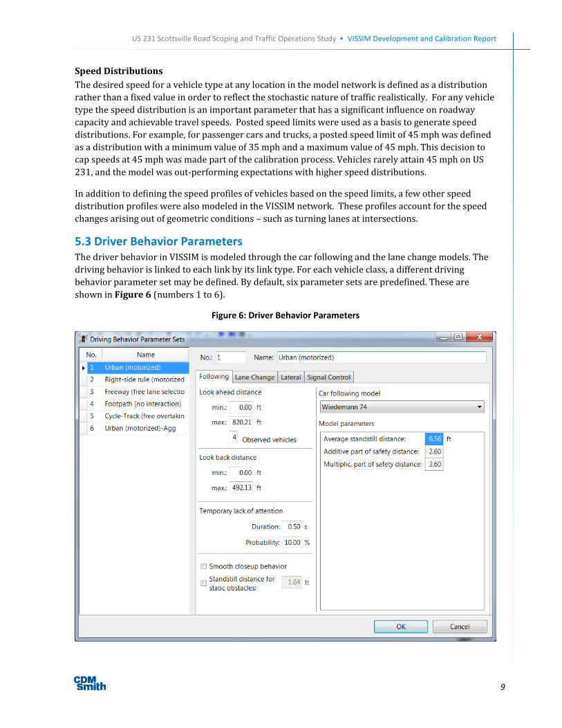
5.3 Driver Behavior Parameters
The driver behavior in VISSIM is modeled through the car following and the lane change models. The driving behavior is linked to each link by its link type. For each vehicle class, a different driving behavior parameter set may be defined. By default, six parameter sets are predefined. These are
shown in Figure 6 (numbers 1 to 6).
Figure 6: Driver Behavior Parameters

US 231 Scottsville Road Scoping and Traffic Operations Study • VISSIM Development and Calibration Report
10
No correlation was assumed between vehicle type and the driver behavior. Drivers were assumed to behave differently under curved sections, or sections with inadequate sight distance, as compared to straight sections. Thus, the parameters described here apply equally to all vehicle types, but were
adjusted for each link type.
Car-Following Model
VISSIM includes two car-following models – urban driver and freeway driver. Only the urban driver type was used. The car-following mode of the urban driver model is named Wiedemann74 and includes six tunable parameters. Suitable values and variations of these car following behavior parameters helped in reproducing the real-world driving behavior. Table 1 shows the car following driver behavior parameters used for this study, and do not necessarily reflect default VISSIM values. Refer to table notes for definitions and explanations. Discussions with PTV resulted in an adjustment of the “temporary lack of attention parameter” to more accurately reflect driver behavior. The
duration was set to 0.5 sec at a 10% probability.
Table 1: Car Following Driver Behavior Parameters
Car Following Parameters Driver Behavior Model
Urban Default Urban Aggressive Urban Mild
Look Ahead Distance (ft) 0 – 820.21 0 – 820.21 0 – 820.21
Observed Vehicles 4 6 4
Look Back Distance (ft) 0 – 492.13 0 – 492.13 0 – 492.13
Temporary Lack of Attention
Duration (sec) 0.5 0 0
Probability (%) 10 0 0
Average Standstill Distance (ft) 6.56 5.00 8.00
Additive Part of Safety Distance 2.60 1.50 2.50
Multiplicative Part of Safety Distance 3.60 2.50 3.50
Note: 1. The Look ahead distance defines the distance that a vehicle can see forward in order to react to other vehicles either in
front or to the side of it. The minimum value is important when modeling lateral vehicle behavior. Especially if several vehicles can queue next to each other (e.g. bikes) this value needs to be increased to 60-100 ft in urban areas. The maximum value is the maximum distance allowed for looking ahead. It needs to be extended only in rare occasions.
2. The number of Observed vehicles affects how well vehicles in the network can predict other vehicles´ movements and react accordingly.
3. The Look back distance defines the distance that a vehicle can see backwards in order to react to other vehicles behind. The minimum value is important when modeling lateral vehicle behavior. Especially if several vehicles can queue next to each other (e.g. bikes) this value needs to be increased to 60-100 ft in urban areas. The maximum value is the maximum distance allowed for looking backward.
4. Temporary lack of attention (“sleep” parameter): Vehicles will not react to a preceding vehicle (except for emergency braking) for a certain amount of time. Duration defines how long this lack of attention lasts. Probability defines how often this lack of attention occurs. The higher both of these parameters are, the lower the capacity on the corresponding links will be.
5. Average standstill distance defines the average desired distance between stopped cars. Additive part of desired safety distance and multiplicative part of desired safety distance affect the computation of the safety distance. The higher these values, the higher the distance between stopped cars.

US 231 Scottsville Road Scoping and Traffic Operations Study • VISSIM Development and Calibration Report
11
Lane Change Parameters
VISSIM also includes a different set of parameters which govern how vehicles change lanes as they travel from origin to destination. Eight tunable lane change parameters are available and suitable values and variations of these parameters helped in reproducing the real-world driving behavior. Table 2 shows the parameters that were used in this study, which do not necessarily reflect default
values (refer to table notes for definitions).
Table 2: Lane Change Parameters
Lane Change Parameters Driver Behavior Model
Urban Default Urban Aggressive Urban Mild
Maximum Decelration (ft/sec2)
Own -13.12 -16.00 -10.00
Trailing Vehicle -9.84 -12.00 -8.00
-1 ft/sec2 per distance (ft)
Own 100 75 100
Trailing Vehicle 100 75 100
Accepted Deceleration (ft/sec2)
Own -3.28 -3.28 -3.28
Trailing Vehicle -3.28 -3.28 -3.28
Waiting Time Before Diffusion (sec) 60 60 60
Minimum Headway (front/rear) (ft) 1.64 1.64 1.64
Safety Distance Reduction Factor 0.70 0.55 0.65
Cooperative Lane Changed Allowed? No No No
Note: 1. The aggressiveness of lane change is defined by deceleration thresholds both for the lane changer (Own) and the vehicle
that he is moving ahead of (Trailing). The range of these decelerations is defined by the Maximum and Accepted Decelerations. In addition, a reduction rate (as meters per 1 m/s²) is used to reduce the Maximum Deceleration with increasing distance from the emergency stop position.
2. Waiting time before diffusion defines the maximum amount of time a vehicle can wait at the emergency stop position waiting for a gap to change lanes in order to stay on its route. When this time is reached the vehicle is taken out of the network (diffusion) and a message will be written to the error file denoting the time and location of the removal.
3. Min. Headway (front/rear) defines the minimum distance to the vehicle in front that must be available for a lane change in standstill condition.
4. During lane changes, the safety reduction factor is regarded. During any lane change, the resulting shorter safety distance is calculated as follows: original safety distance x reduction factor. The default factor of 0.6 reduces the safety distance by 40%. After the lane change, the original safety distance is regarded again.
5. If vehicle A observes that a leading vehicle B on the adjacent lane wants to change to the (A) lane, then vehicle A will try to change lanes itself to lane (B) in order to make room for B.
6.0 Random Seed Variations Once the calibrated model was established, the calibrated parameter set was run with at least five different random seeds. The random seed affects the realization of the stochastic quantities in VISSIM, such as inlet flows and vehicle capabilities. For congested corridors, at least five seed runs are generally recommended. The results presented in Section 7.0 were based on the average of at least
five different random seeds.

US 231 Scottsville Road Scoping and Traffic Operations Study • VISSIM Development and Calibration Report
12
7.0 Results This section describes how the calibration goals were met for the US 231 study area.
7.1 Goal 1: Identification of PM peak period queuing
Field observations indicated that several locations experience queuing, most notably at Lovers Lane,
Cave Mill Road, and Three Springs Road.
The calibrated VISSIM model for the PM peak period replicates the real world driving behavior and shows queuing at the same intersections. Table 3 identifies the average and maximum queues at the signalized intersections during this time. Maximum queues were observed in the southbound
direction.
Table 3: PM Peak Hour Intersection Queues
Intersection:
US 231 at
Eastbound Queue (ft) Westbound Queue (ft) Northbound Queue (ft) Southbound Queue (ft)
Average Maximum Average Maximum Average Maximum Average Maximum
Three Springs Rd 48.6 248.9 102.8 341.3 118.8 1211.6 237.3 752.6
Pascoe Blvd 66.6 477.8 60.8 373.3 23.4 526.0 28.6 248.2
Greenwood Square 47.9 427.4 33.4 267.6 43.0 500.2 23.8 345.6
Cave Mill Road 153.7 904.4 190.0 609.9 58.8 612.1 38.1 458.5
Bryant Way 55.8 280.0 211.2 608.4 7.2 207.5 7.3 247.5
Lovers Lane 59.5 370.1 59.3 312.8 40.9 307.5 87.7 509.9
7.2 Goal 2: Model link versus observed flows to meet criteria
The goal for the calibrated VISSIM model is for the GEH statistic, a calculation similar to a chi-squared test, to be less than 5.0 for 85% of individual link flows. GEHs in the range of 5.0 to 10.0 may warrant investigation. Table 5 shows the GEH statistic for each approach. The highlighted cells represent the approaches for which the criteria are not met. However, as can be seen from the tables, the
intersection approach volumes meet the established criteria for more than 85 percent of the cases.
Table 4: GEH Statistics by Approach
Intersection:
US 231 at Eastbound Westbound Northbound Southbound
Three Springs Rd 0.2 0.3 1.7 1.9
Pascoe Blvd 0.2 0.4 1.9 2.0
Greenwood Square 0.4 1.0 2.0 1.1
Cave Mill Road 0.4 0.1 2.0 2.1
Bryant Way 0.2 0.7 2.0 1.2
Lovers Lane 0.1 0.4 0.7 1.4

US 231 Scottsville Road Scoping and Traffic Operations Study • VISSIM Development and Calibration Report
13
7.2 Goal 3: Model link versus observed travel time to meet criteria
The goal of the calibrated VISSIM model was to obtain modeled average travel time to be within 15 percent or one minute for US 231 study area. Table 5 shows this travel time comparison. Overall, the northbound and southbound travel times are within 20 seconds of the observed travel times during
the peak hour.
Table 5: PM Peak hour Travel Time and Speed
From To Distance
(mi)
Travel Time (sec) Speed (mph)
VISSIM Field
Runs
%
Diff. VISSIM
Field
Runs
%
Diff.
US 231 SB Lovers Ln Three Springs Rd
1.00 224 204 9% 16.1 17.6 -9%
NB Three Springs Rd Lovers Ln 175 193 -10% 20.6 18.7 9%

US 231 Scottsville Road Scoping and Traffic Operations Study • VISSIM Development and Calibration Report
14
8.0 Existing Conditions (2013) MOEs After the existing conditions VISSIM model was calibrated, the measures of effectiveness (MOEs) for existing conditions were obtained for the PM peak hour. Table 6 shows the intersection and approach delay and Level of Service for this time period. The values below are taken from VISSIM, while values shown in the US 231 Scottsville Road Scoping and Traffic Operations Study are from an alternate
software package, Synchro.
Table 6: Existing (2013) PM Peak Hour Intersection LOS
Intersection Delay (s) LOS Approach Delay (s) LOS
Ken Bale Blvd / Three Springs Rd 58.6 E
Northbound US 231 51.8 D
Southbound US 231 69.3 E
Eastbound Three Springs Rd 42.0 D
Westbound Ken Bale Blvd 61.3 E
Pascoe Blvd 23.9 C
Northbound US 231 17.5 B
Southbound US 231 19.0 B
Eastbound Pascoe Blvd 66.2 E
Westbound Pascoe Blvd 87.2 F
Greenwood Square 17.4 B
Northbound US 231 16.4 B
Southbound US 231 12.2 B
Eastbound Greenwood Square Access 38.8 D
Westbound Frontage Rd Access 53.5 D
Cave Mill Rd/Shive Ln 41.9 D
Northbound US 231 29.5 C
Southbound US 231 27.4 C
Eastbound Cave Mill Rd 67.0 E
Westbound Shive Ln 85.5 F
Bryant Way 17.4 B
Northbound US 231 8.4 A
Southbound US 231 7.1 A
Eastbound Mall Access 39.0 D
Westbound Bryant Way 93.2 F
Campbell Ln/Lovers Ln 46.7 D
Northbound US 231 35.4 D
Southbound US 231 50.6 D
Eastbound Campbell Ln 46.1 D
Westbound Lovers Ln 57.3 E

MINUTES Traffic Micro-simulation Meeting
US 231 – Warren County – Item #3-8702.00 KYTC Central Office Frankfort, Kentucky
February 7, 2014 9:00 AM EST
An informational meeting for the US 231 Scottsville Road Scoping and Traffic Operations Study (Warren County) was held at 9:00 a.m. EST on Friday, February 7, 2014 in Frankfort, Kentucky. The purpose of the meeting was to discuss the benefits of traffic micro-simulation for this project and to present the existing conditions model in its current form. Participants in the meeting represented the Kentucky Transportation Cabinet (KYTC) District 3 and Central Offices and the consultant firm, CDM Smith. Meeting attendees included the following persons: Shane McKenzie KYTC, Central Office Planning Mikael Pelfrey KYTC, Central Office Planning Lynn Soporowski KYTC, Central Office Planning Jonathon Reynolds KYTC, Central Office Planning Barry House KYTC, Central Office Planning Jay Balaji KYTC, Central Office Planning Daniel Hulker KYTC, Central Office Planning Scott Thomson KYTC, Central Office Model Team Lead Deneatra Henderson* KYTC, District 3 Planning Brad Johnson CDM Smith Steve De Witte CDM Smith *Joined via teleconference. A summary of the key discussion items and decisions from this meeting are provided below. Welcome and Introductions: Shane McKenzie, KYTC Co-Project Manager, began the meeting, welcoming attendees and asking for formal introductions from all. Traffic Micro-simulation: Brad Johnson, CDM Smith project manager, briefly outlined the project scope and introduced the micro-simulation model chosen for this project, VISSIM. VISSIM is being used to analyze existing and future year traffic for the PM peak only. VISSIM uses a link-connector network for traffic to operate upon. Signal timings were provided by KYTC and are depicted accurately in the model. While push-buttons are located at several intersections, pedestrian timings were not used in the existing conditions model due to a lack of data concerning pedestrian movements. The model uses an origin-destination matrix (developed using engineering judgment) to distribute traffic throughout the network. Scott Thomson asked if the simulation only runs for the peak hour. Steve De Witte responded that the simulation runs for ninety minutes, with the first thirty minutes used to seed, or load, the network to match traffic expected at the start of the analysis period. At this time, Steve De Witte presented the un-calibrated model, which led to further discussion.

Scott asked about the importance of a calibrated existing conditions model. Brad explained that a calibrated existing conditions model is critical. If the model is not simulated existing conditions accurately, any results which come from a future-year model are fatally flawed. Brad further explained that the model is calibrated by matching travel time runs conducted in the field to the travel time the model outputs. Travel time was recorded in the field using a stopwatch. Scott asked if GPS technology could be used instead to better capture time spent waiting at signalized intersections. Brad responded that this is an option in the future. Daniel Hulker asked if the volumes seen in the model match those counted in the field. Brad answered that this is another step in the calibration process to verify. Scott asked about several parameters which can be adjusted within the model, including gap acceptance, reaction time, and vehicle acceleration and deceleration. All of these parameters are held to program defaults in the absence of compelling data to warrant their change. Scott said he would provide CDM Smith newly acquired VIN data for Warren County showing vehicle breakdown by type before Wednesday, February 12. Scott asked about the coding of the frontage road, and would prefer to see seeding occur at a new intersection off the frontage road rather than splitting the frontage road and seeding at the endpoints. Brad said CDM Smith would investigate this option. A question was asked how the model would operate if the frontage road was removed. Brad responded that each driveway would become its own intersection, and any additional capacity added to Scottsville Road would result in the new lane functioning as a continuous acceleration-deceleration lane. Scott asked if the project team was missing interaction with the frontage road by only counting the PM Peak, due to the number of fast-food breakfast options on the frontage road. Brad responded that week-long analysis was done on the corridor using tube counters, which showed a larger peak in the afternoon. CDM Smith will provide inputs for vehicle composition, a map of the project area for a Geotech request, and an email making a formal request for the VIN data. CDM Smith will also provide Deneatra Henderson the Alternative 5 Synchro. Deneatra will provide the Environmental Justice report in one week. With no further discussion, the meeting was adjourned at 10:15 am.


![VISSIM Lab Assignment_Final[1]](https://img.pdfslide.us/doc/110x75/55cf9aa0550346d033a2a24a/vissim-lab-assignmentfinal1.jpg)