Embed Size (px)
Citation preview

APPENDIX A. INTERPRETATION OF DRAWN INFORMATION
It is essential to understand the symbols shown on engineering services drawings, as these provide a speedy and standard method of reading the drawing.
The field of symbols is in a state of flux, as British Standards are being harmonized into the new CEN (European Committee for Standardization) standards, which cover the EU, and ISO (International Standards Organization) standards covering countries throughout the world. Before listing symbols on a drawing it is prudent to ensure that they meet the latest requirements of the above organizations.
The list below gives some indication of the wide range of publications that have to be consulted in order to obtain a symbol. By the year 2000, however, most of these will have merged into new CEN or ISO standards.
• BS 1553 : 1977 General engineering Part 1. Piping systems and plant
• BS 1635 : 1990 Fire protection drawings • BS 6217 : 1989 Graphical symbols for electri
cal systems • BS 3939: Parts 1-13 (various dates) Graphi
cal symbols for electric power, telecommunications and electronic diagrams
• ISO 4067-1 Graphical symbols for plumbing, heating, ventilation and ducting
• BS EN 60617 Graphical symbols for diagrams • BS EN 61175 Designations for signals and con-
nections (electrical) • BS 6465 : 1984 Sanitary installations • BS 8005 : Parts 0-5 Sewage • BS 8010: Various parts and sections of codes
of practice for pipelines • BS 6700: 1987 Specification for design instal
lation, testing and maintenance of services supplying water for domestic use within buildings and their curtilage
• BS 5572: 1978 Code of practice for sanitary pipework
The abbreviation CENELEC may be seen; this relates to the European Electrical standards, which are replacing the British Standard specifications.
SYMBOLS ASSOCIATED WITH THE COMPONENTS OF BUILDING SERVICES I NST ALLA liONS
The symbols below are produced with the permission of the British Standards Institution. Care has to be taken in using computer-aided design (CAD) packages, as the symbols used in these may not meet the requirements of international standards.
128 An Introduction to Building Services
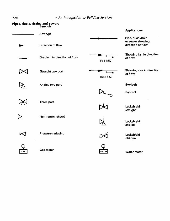
Pipes, ducts, drains and sewers Symbols
Any type
Direction of flow
Gradient in direction of flow
1><1 Straight two port
Angled two port
Three port
1>1 Non-return (check)
Pressure reducing
Gas meter
c:::::: Fall1:50
c:::; Rise 1:50
Applications
Pipe, duct, drain or sewer showing direction of flow
Showing fall in direction of flow
Showing rise in direction of flow
Symbols
Ball cock
Lockshield straight
Lockshield angled
Lockshield oblique
Water meter

Appendix A 129
Manholes and gullies
Symbols
CJ D Rectangular Rectangular backdrop manhole
manhole
0 Circular manhole Circular backdrop manhole
[ZJ Gully, any type
Elements Symbols
Twin outlet tap
[:] Sink, any type
T Sink, any type
Symbols
D Shower tray
II all Bath
we with close-coupled ~ Urinal bowl cistern

130 An Introduction to Building Services
Pipework components
Symbols
I I
Natural convector Pump, any type
I I
I C><::J Forced (fan) convector EJ Centrifugal pump
Radiant panel e Expansion vessel
Radiant strip
Radiator
EJ Unit heater

Appendix A 131
Air-handling equipment
Symbols
Fan, any type [!] Heater battery
=---@ Centrifugal fan ~ Cooler battery
~ Filter [f] Humidifier
a Moisture eliminator ~ Attenuator
Ductwork
Symbols
Airflow direction, inwards Grille/diffuser, face view
- Airflow direction, outwards Grille/diffuser, edge view
Damper in section

132 An Introduction to Building Services
Electrical services
Switches Power outlets
Elements Symbols
One-pole switching device Socket outlet to BS 1363, any type
i Two-pole switching device Socket outlet to BS 1363 with indicating lamp
~ Three-pole switching device r( Socket outlet to BS 1363 with one-pole switch
2 Socket outlet to BS 1363,
/ Four-pole switching device ~ two gang
Pull cord operation
Symbols
d One-pole, one-way
_f One-pole, two-way

Appendix A 133
Electrical services Supply and distribution
Symbols Symbols
Electricity meter ? Tapping-off point
00 I 1.. Live (or phase) wire
Transformer
!. Neutral wire
EE I
Contactor
//If Three-phase and neutral cable
Starter
I Wiring goes upwards
1 Wiring goes downwards Distribution board
o-, Isolator -1 Vertical wiring
j_ Terminal to be connected 0 Box - to earth
8 Junction box
* Circuit breaker
X Lighting outlet
~ Neutral link Strip light, fluorescent
~ Fuse Double strip light
X Emergency light position

APPENDIX B. UNITS AND EQUATIONS
In any study of building services engineering it is essential to have an understanding of the units and equations used, as these provide an appreciation of the plant operation.
Rather than just giving a shopping list of the units, some of the basic equations encountered have been given, stating their application and the nature of the units involved.
EQUATIONS USED IN HEAT AND MASS FLOW
A very important equation is that used in the determination of the sensible heat flow that takes place in a fluid, which may be either liquid or air.
Sensible heat
flow
Mass flow in X Specific heat X Temperature
unit time capacity difference
Inserting the units used in this equation:
kW (or kJ/s) = kg/s X kJ/kg oc X oc
Expressing in symbol form:
Q = m X CP X !l.t (1)
An everyday application of Equation (1) is the determination of the water flow rate required for the sizing of a heat emitter.
In calculating the annual energy consumption for heating systems, the use of the kilowatt (1 03 W) results in a rather cumbersome large number, and it is normal to use the megawatt, MW (106 W) or gigawatt, GW (109 W).
Once the rate of heat loss from a room is known, a radiator or other type of heat emitter has to be selected. The pipe that supplies water to this radiator must be capable of providing the correct mass flow rate (kg/s) for a given temperature difference. The temperature difference for a low-temperature hot water system is normally taken as being 10 °C (80 °C flow and 70 oc return), the specific heat
capacity, cp, of water is taken as 4.18 kJ/kg 0 C. Note that the value of CP varies with temperature and pressure.
If the mass flow rate is too low, the radiator will give out less heat than required, resulting in inadequate room air temperature during winter conditions.
A simple example will illustrate the use of this equation.
Example
A radiator catalogue states that a given-sized radiator will emit 3.0 kW. Determine the mass flow rate of water that is required to the radiator if the flow temperature is 80 °C and the return temperature is 70 °C.
Solution
Use Equation (1) : Q = m X C X !1t p
Transposing in order to determine the mass flow rate (kg/s):
m = Q
where Q = heat output required from radiator (3 kW); !l.t = temperature difference between the flow and return (10 °C); at the mean water temperature in the radiator (75 °C), the specific heat capacity cp is 4.194 kJ/kg °C.
Hence the mass flow rate required at these conditions is:
m 30 4.194 X 10.0
0.07153 kg/s
Should the heating application require a warm air system to be used, the value of C for dry air would
p be taken as being approximately 1.01 kJ/kg °C. The

Appendix 8 135
temperature difference in this case would normally be slightly higher than 10 °C.
HEAT LOSS
The rate of heat loss from a space can be expressed simply as:
(2)
where QP = the heat output of the boiler plant (kW); Qc = the rate of heat loss through the elements of the building fabric (kW); and
Qc = l: (A X U) At
where l: = the summation of; A = the area of the elements considered (m2), i.e. wall, glass, etc.; U = the thermal transmission coefficient (W /m2 oq (the values of U must meet the requirements of the Building Regulations).
Qv = the rate of heat loss by ventilation (kW) = (0.33 NV) At; At = the difference in temperature between the inside design temperature (tai) and the outside design temperature (t.0 ); N = the number of air changes that take place per hour (for natural ventilation see CIBSE Guide A4, while for mechanical ventilation see CIBSE Guide B2); V = volume of the space being considered (m3). The constant 0.33 is determined from:
Specific heat capacity, CP X Air density, p
Seconds in one hour
That is:
1010 J/kg oc X 1.2 kg/m3 = 0.33 3600
(3)
The answers obtained for the value of QP are only approximate, as the mode of heating must be considered, (radiators or convectors). The method of heating used requires correction factors F 1 and F 2 to be applied to the values of Qc and Qv. These correction factors are obtained from the CIBSE Guide A9 Table A 9.1-A 9.7.
In many instances, the U value has to be calculated from:
u =-1-l:R
(4)
where l: R is the summation of the various structural thermal resistances (m2 °C/W). The value of R is determined by dividing the thickness (m) of the material by its thermal conductivity A (W/m 0 C). The values of thermal conductivity and surface resistance are obtained from the CIBSE Guide A3.
The following equation is used to determine the U value for a composite structure:
u = (5)
where R,i = inside surface resistance (m2 °C/W); R. = resistance of air gap (m2 °C/W); R,0 = outside surface resistance (m2 °C/W); l = thickness of material (m); A = thermal conductivity of material (W/m 0 C); and suffices 1, 2, etc. relate to the material.
The above equation can be extended to include any number of l(A. Note: this is the same as R.
To determine the surface temperature:
Q1 = U X A X At
or
or At=~ X Q1 The inside surface temperature is determined from:
(6)
While the external surface temperature is determined from:
(7)
where R,i = inside surface resistance (m2 °C/W); R,o = outside surface resistance (m2 °C/W).

136 An Introduction to Building Services
THE CONTINUITY EQUATION
Use is made of this equation in order to determine any one of three variables when the other two are known.
The variables considered may relate to the flow of air, or water, and are:
Q quantity of flow, m3 /s for air and kg/s for water;
A = the cross-sectional area of the pipe or duct (m2);
V the velocity of fluid in the duct or pipe (m/s)
The equation is
Q=AXV (8)
A typical application of this equation is that of duct sizing.
Example
A run of ductwork in an air-conditioning system has to carry 2 m3/s of air at a velocity of 10 m/s. What is the required cross-sectional area of the duct?
Answer
We apply Q =A XV, where Q = 2m3/s, A=?, V = 10m/s.
Transposing:
Therefore
A = 2.0 10
2 0.2m
Hence a duct having a cross-sectional area of 0.2 m2
is required; this may be either circular or rectangular.
ELECTRICAL
When electrical heating is used it is necessary to determine the rating of an element, in order that the required kW output is provided.
Example
A 3.0 kW immersion heater is fitted in a water tank of 0.2 m3 (200 litre). Determine the time taken to heat the water from 10 °C to 80 °C:
(a) assuming the process is 100 per cent efficient. (no heat loss);
(b) assuming the efficiency is 90 per cent (10 per cent of the heat input is lost by poor quality thermal insulation).
Answer
The basic equation is Q = m X C X flt, where Q p
= 3.0 kW; 1m3 of water weighs 1000 kg or 1 tonne and therefore 0.2 m3 = 200 kg; flt = temperature difference = (80 - 1 0) = 70 °C.
(a) The electrical input is 3.0 kW X time in hours = 3 X t. As 1 kWh = 3.6 X 10⁶ J, heat output:
Q = kg X flt X CP
Taking CP as 4190 J/kg °C:
Q = 200 X 70 X 4190 3.6 X 10⁶
16.29 kWh
Hence 3 t = 16.29
and t = 1~:~9 = 5.43 hours = 5 hours 25.8 minutes
(b) In this case the heating process is only 90 per cent efficient, so the heating process will take longer than that in case (a):

Appendix 8
t = 5.43 hours X 1~g
= 6.03 hours = 6 hours 1.8 minutes
As case (b) takes longer to heat up, the electrical usage will be greater than that in case (a): hence the running costs will be greater, showing the need for thermal insulation.
COMBUSTION
Combustion calculations allow the determination of the quantity of fuel necessary to provide sufficient heat to meet a building's heat losses.
In order to carry out this calculation, the calorific value of the fuel is required; this is the heat contained in a unit weight or volume of fuel. For a solid fuel the units of calorific value are kJ/kg; for a liquid fuel they are MJ/litre, and for a gaseous fuel they are MJ/m3•
In theory, all the heat contained in the fuel can be used. If the fuel contains moisture or hydrogen, steam is produced, which on leaving through the chimney will take with it heat that is not used for the building's heating system.
The theoretical heat content in the fuel is known as the gross calorific value: hence the moisture liberated up the stack is reducing the useful heat contained in the fuel. In making allowances for this, the net calorific value is used. This is obtained by deducting the latent heat in the vapour content of the combustion products, when cooled, from the gross calorific value.
Typical calorific values are listed in Table B 1. The use of these values is best shown by means of an example.
Table B.l Typical calorific values
Fuel Gross CV Net CV (MJ!kg) (MJ!kg)
Coal 30.60 29.65 Gas oil 45.60 42.80 Natural gas 53.42 48.16
137
Example
A building has a design heat loss of 600 kW. Determine how many of kg of solid, liquid or gaseous fuels are required if the combustion efficiency of each burner is 80 per cent. For simplicity, all the calorific values have been given as MJ/kg.
Answer
If the combustion process is 100 per cent efficient, the fuel required is simply:
kg of fuel required Heat requirement in kW (9) Net heat content in fuel kJ/kg
For coal
600 kW = 0.0202 kg/s 29650 kJ/kg
Note that the MJ/kg must be converted to kJ/kg for consistency with the kW. As the combustion process is only 80 per cent efficient, the fuel required will have to be greater than this calculated amount by:
0.0202 X ~~O
= 0.0252 kg/s of coal
The calculations for gas oil results in a requirement of 0.0175 kg/s, while natural gas is 0.01557 kg/s.
Considering the units used above:
1 J = 1 W/s
Hence:
Heat load kW (kJ/s) kJ/kg
which on cancelling out gives kg/s.

ABS 6 accelerated systems 56 access
adjustable platforms for 118 for exterior maintenance 116
access shaft 31 active control 113 activity levels 42 actuators 61 air change rate 69 air conditioning 70 air distribution, methods of 68 air temperature 42 air velocity 42 air-handling equipment 131 air-pressure fluctuations 20 air-water systems 72, 74 all-air systems 72-73 anti-flash margin 50 atmospheric burners 97 atmospheric pressure 76 auto-pneumatic systems 6 axial flow fans 78
back inlet gullies 28 back siphonage 4 back-drop manholes 31 backward-curved fans 79 baths 19 bedding 33 Belfast sink 18 boiler heat transfer 49 boilers 48 boiling point 76 bottle trap 21 British Standards 127 bulk waste 37 burners 97
dual gas/oil 97 magnetic types 98 pressure jet 54
bus bars 91
cables down-rated 90 mineral insulated 90 types of 89
calcium carbonate (limestone) 2
INDEX
carbon dioxide 113 carbon filters 80 cartridge fuses 86 cast iron 45 cast iron boilers 49 CEN 127 CENELEC 90 central heating 43 cesspools 35 chain grate stokers 53 channels 30 chilled ceilings 7 4 Chimney Memorandum 1968 55 chimneys 55 CIBSE guide 42 circuit breakers, miniature 87 circulation, mode of 56 Clean Air Act 1956 55 column radiators 45 combined heat and power 63 combined trap 20 combustion gas detectors 116 comfort factors 42 communal waste 37 compound interest 121 concealed grids 105 condensing 76 condensing boilers 51 contract loads 109 contract speeds 109 control sub-systems 43, 60 controllers 60 convectors 46 cooling 71 copper 6 cradles, powered 119 cylinders 13
deep cavities 106 dehumidification 71 delta connections 84 demineralisation 3 design shapes 117 dew-point temperatures 71 dezincification 2 diffusion 80 direct-fired radiant heating 47 disposable filters 80 distribution, of domestic hot water
(solar) 14 district heating 62 domestic hot-water temperature 14 domestic layout, typical 88 downward systems 69 drain termination 35 drainage, above ground 19 drains 128 dry bulb temperature 71 dry risers 115 dry systems 113 dry-powder extinguishers 113 dual-duct systems 73 ducts 128 ductwork 80
earthing 91 electric immersion heaters 10 electric resistance cables 48 electrical circuits, simple 82 electrical grinders 18 electrical regulations 92 electricity 82
off-peak 62 Electricity Acts 93 electricity generation and
distribution 83 electricity services supply and
distribution 132, 133 electrohydraulic drives 109 electrode boilers 50 energy conversion sub-systems
43, 48 equations 134 escalators 110 evaporation 42, 76 evaporators 77 expansion valves 77 exposed grid systems 105 external access 103 external access equipment 117
fan coil units 74, 75 fans 78
vane-axial 78 feed and expansion tanks 12 filtering 71 filters 80
140
disposable 80 reusable 80
filtration 1, 37 final sub-circuits 87 fire detection 115 fire-fighting appliances, fixed 113 fire-fighting installations 112 fire-fighting systems, selection
of 116 firing methods 52 first-aid measures 113 flame detectors 116 flame triangles 112 floor trenches 104 floor-warming systems 47 flue discharges 99 flues 98 foam cylinders 113 forced convectors 46 frequency 84 fuel oils, classification of 52 fuels 51 fuses 86
high-breaking capacity 86 fusing currents 86
Garchey system 39 gas burners 54 gas distribution 95 gas fuel burners 95 gas installations 95 gas supplies 96 gas turbines 83 gaseous fuels 52 gate valves 5 generators 83 glass-reinforced plastics (GRP) 18 glazed fireclay 18 gravity systems 56 greenhouse effect 76 group control 110 group heating 62 gullies 28, 129
hard water 2 heat detectors 116 heat generators 48 heat loss 135 heat output 44 heat pumps 78 heating systems 43 high-breaking capacity fuses 86 high-level WC's 16 high-rise buildings 6 horizontal group 102
Index
hose reel systems 113-114 hot water, instantaneous 11 hot water systems
high temperature 56 low temperature 56, 58 unvented 14
hydrated sodium sulphate (Glauber salts) 2
hydraulic jump 20
lEE regulations 93 impaction 80 incineration 38 indirect systems 12 induced siphonage 22 induction effect 74 induction units 74 inlets, to drainage gullies and
traps 28 inspection chambers 32 insulators 90 integral traps 21 interception 80 internal access 103 International Standards 94 invert levels 30 ionization detectors 115 ISO 127
jointing 33
ladders 118 laser detectors 116 latent heat 59, 71, 76 Legionella pneumophilia 3 lift cars 1 09 lift control systems 110 lift and escalator installations 107 lifts, types of 109 lighting systems 91 liquid fuel burning 53 liquid fuel (petroleum) 51 liquid petroleum gas 52 local heating 43 local units 13
magnesium sulphate (Epsom salts) 2 maintenance costs 120 manholes 30, 129 mean radiant temperature 42 mechanical extract, induced input 67 mechanical input, forced extract 67 mechanical input, mechanical
extract 68 mesh 84 MET 42 micro systems 59 micrometre 80 mineral insulated cables 90 miniature circuit breakers 87 minibore systems 59 mixed upward-downward system 69 moisture content 71 mud gullies 29
national grid 83 natural convectors 44, 46 natural gas 52 natural ventilation 66 negative suction 20
ohm 82 Ohm's law 83 one-pipe drop 57 one-pipe ring main 57 one-pipe systems 25, 56-57 open systems 56 operating temperature 56
package shell boilers 49 panel radiators 44 partially separate systems 27 passive (Trombe) walls 62 pathogenic bacteria 1 percentage saturation 71 perimeter induction units 74 permanent equipment 118 permanent hardness of water 2 petrol/oil interceptors 29 phase conductors 84 pipe material 33 pipe sizing 7 pipe-line collection systems 38 pipes 128 plate collectors 61 plenum systems 67 plug formation 20 pneumatic systems 39 positive compression 20 power cables, uprated 90 powered trolleys and cradles 119 pressure cylinders 7 pressure jet burners 54 pressure vessels 58 primary air 53, 74 primatic cylinders 13 private drainage 27

provision, for fire-fighting personnel 116
psychrometries 71 PVC cables 90 PVC-U 6
radial blades 79 radiant panels 4 7 radiator shelves 45 radiators 44 rainfall 1 raised floors 106 ranges 18 refrigeration processes, basic 76 refuse containers, individual 37 refuse disposal 36 replacement costs 120 reusable filters 80 ring circuits 87 riser systems 113 running costs 120
salt-glazed ware 33 sanitary appliances 16 saturated vapour temperature 76 saturation percentage 71 SE-ducts 100 secondary air 53, 74 self-cleansing velocity 27 self-siphonage 22 sensible heat 59, 71 sensing elements 60 septic tanks 36 service cables 90 service integration 102 services costs 120 sewers 128 silica (sand) 2 single operative systems 118 single stacks 25 single-phase supplies 84 single-point supplies 13 sink grinders 38 Sitz baths 19 soil stack 25
Index
small bore heating 59 smoke detection 115 sodium chloride (common salt) 2 sodium sulphate, hydrated (Glauber
salts) 2 soft water 2 soil pipes and pipework 20, 24 solar heating 61 solid fuel burning 51-52 special traps 22 specific enthalpy 71 specific volume 71 sprinkler systems 113 stack effects 66 staging 118 stainless steel 6, 18 standard atmosphere 76 star point 84 steam systems 59 steam traps 60 step-up transformers 83 sterilisation 1 stopcocks 5 suspended ceilings 1 05 symbols 127 system layout 56
taps 18 tanks, feed and expansion 12 temperature 77 temporary cradles 118 temporary hardness 2 thermal comfort 42 thermocouples 98 three t's 112 three-phase supplies 84 three-pipe systems 75 three-wire supplies 84 traction drives 109 transmission lines 83 travelling ladders 118 trolleys, powered 119 trunking 106 tube-axial fans 78 two-pipe drop heating systems 57
two-pipe heating systems 57 with direct return 57 with reversed return 57
two-pipe rising systems 57
U-ducts 100 ultrasonic detectors 116 unit heaters 46 unitary systems 72, 75 units 134 up-rated power cables 90 upward ventilation 68 urinals 17 utilization sub-systems 44
vane-axial fans 78
141
vapour compression cycle 76 vapour pressure 42 vaporizing-liquid extinguishers 113 variable air volume 73-74 vertical ducts 102-1 03 visible smoke detection 115
walkways 102 wash basins 1 7 waste pipes 20 water
hard 2 soft 2
water closets (WCs), high level 16 water extinguishers 113 water supplies 1 water-borne to sewer 39 water-tube boilers 50 watts 82 WCs, high level 16 wet bulb 71 wet and dry systems 113-114 wet hydrant risers 115 wet systems 60, 114 wide open condition 79 winter air-conditioning cycle 72 working chambers 31