Embed Size (px)
Citation preview

Cricket Valley Energy Project – Dover, NY
Draft Environmental
Impact Statement
Appendix 5-B: Conceptual Stormwater Report –Laydown Site
©2010 Chazen Engineering, Land Surveying & Landscape Architecture Co., P.C.
Conceptual Stormwater Report Issued for SEQRA DEIS Review
Cricket Valley Energy: Off-Site Construction Parking and Laydown Area
Town of Dover Dutchess County, New York
October 1, 2010
Prepared for: Cricket Valley Energy Center, LLC
31 Milk Street Boston, Massachusetts

Conceptual Stormwater Report
Issued for SEQRA DEIS Review
Cricket Valley Energy: Off-Site Construction Parking and Laydown Area
Town of Dover Dutchess County, New York
October 1, 2010
Prepared by:
Chazen Engineering, Land Surveying & Landscape Architecture Co., P.C. 21 Fox Street
Poughkeepsie, New York (845) 454-3980
Dutchess County Capital District North Country (845) 454-3980 (518) 273-0055 (518) 812-0513
Conceptual Stormwater Report Cricket Valley Energy – Off-Site Construction Parking and Laydown Area Page 3
TABLE OF CONTENTS
1.0 INTRODUCTION .............................................................................................................. 5
1.1 Project Description.........................................................................................................6
1.2 Regulatory Review.........................................................................................................7
2.0 SITE CHARACTERISTICS............................................................................................... 9
2.1 Existing Land Use and Topography ..............................................................................9
2.2 Soils and Groundwater...................................................................................................9
2.3 Watershed Designation ................................................................................................10
2.4 Receiving Water Bodies ..............................................................................................10
2.5 Rainfall Data ................................................................................................................10
3.0 EROSION AND SEDIMENT CONTROL OVERVIEW ................................................ 12
3.1 Temporary Erosion and Sediment Control Measures..................................................12
3.2 Permanent Erosion and Sediment Control Measures...................................................14
3.3 Inspections, Maintenance, and Reporting....................................................................15
4.0 POST-CONSTRUCTION STORMWATER OVERVIEW ............................................. 17
4.1 Pre-Development Conditions.......................................................................................17
4.2 Post-Development Conditions .....................................................................................17
4.3 Stormwater Quantity Analysis.....................................................................................17
4.4 Stormwater Quality Analysis.......................................................................................19
4.5 Runoff Reduction Volume...........................................................................................20
4.6 Stormwater Control Practices ......................................................................................21
4.7 Soil Testing ..................................................................................................................23
5.0 CONCLUSION................................................................................................................. 25
LIST OF TABLES Table 1: USDA Soil Data ............................................................................................................... 9
Table 2: Rainfall Data................................................................................................................... 11
Table 3: Summary of Pre- and Post-Development Peak Discharge Rates and Detention Requirements ............................................................................................................................... 19
Table 4: Summary WQ Volumes Associated with Each Stormwater Management Area............ 20
Conceptual Stormwater Report Cricket Valley Energy – Off-Site Construction Parking and Laydown Area Page 4
APPENDICES Appendix A: Figures
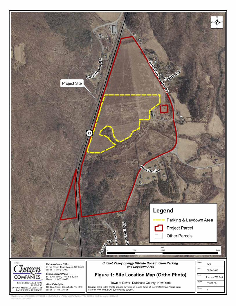
• Figure 1: Site Location Map
• Figure 2: Soils Map
• Figure 3: Pre-Development Watershed Delineation Map (Pocket)
• Figure 4: Post-Development Watershed Delineation Map (Pocket)
Appendix B: Pre-Development Stormwater Modeling
Appendix C: Post-Development Stormwater Modeling
Appendix D: Preliminary Design Calculations
• Detention Volumes
• Water Quality Volume

Conceptual Stormwater Report Cricket Valley Energy – Off-Site Construction Parking and Laydown Area Page 5
1.0 INTRODUCTION
This Conceptual Stormwater Report has been prepared for major activities associated with construction of Cricket Valley Energy (CVE) off-site construction parking and lay down area located in the Town of Dover, Dutchess County, NY.
The preliminary analysis documented in this report is intended to support the State Environmental Quality Review (SEQR) of the application made for a power plant project completed on behalf of the Cricket Valley Energy Center, LLC.
The intent of this document is to present the results of a preliminary storm water evaluation conducted for the proposed conceptual development of the subject property. The following was reviewed:
Conceptual analysis of the pre- and post-development watershed characteristics and discharge rates associated with the proposed development, utilizing theoretical impervious area consisting of gravel, for the 24-hour, 1, 10, and 100-year design storms based upon New York State Storm Water Design Manual, August 2010. The design theory is to provide a system that reduces post-development peak discharge rates to values less than or equal to pre-development peak discharge rates at each storm water discharge point.
Preliminary estimates of the water quality volume, utilizing theoretical impervious area consisting of gravel, to be generated based upon the 90% rule methodology as described in Table 4.1 “New York Storm Water Sizing Criteria” of the NYS Storm Water Management Design Manual dated August 2010.
Description of potential measures to provide qualitative treatment of the water quality
volume; and manage peak rate and volume of runoff during post development condition. (This does not include calculations or size estimates of the recommended facilities.)
Regulatory requirements for State or Local approvals and/or permits regarding storm water management.
The soil erosion and sediment control portion of the conceptual storm water report will include the following:
Outline of the objectives of an erosion control plan.
Description of potential erosion and sediment control measures that could potentially be used.
Description of operations and maintenance (O&M) procedures for each practice.
Description of site assessments and inspections to take place prior to, during, and following construction.

Conceptual Stormwater Report Cricket Valley Energy – Off-Site Construction Parking and Laydown Area Page 6
Although a conceptual analysis has been provided for the stormwater management and sediment control facilities, this report is not an engineering design report to accompany design of facilities.
1.1 Project Description
Cricket Valley Energy Center, LLC is proposing to construct a natural gas-fired, combined-cycle electric generating facility in the Town of Dover, New York (the Project).
The proposed Project would occupy approximately 30 acres (the Site) of a combined 131-acre property (the Property) which consists of four industrially zoned parcels off NY Route 22. The proposed Site has an address of 2241 NY Route 22, Dover, New York.
The Project would generate a nominal 1,000 megawatts (MW) of electricity for the local/regional electric transmission grid through an interconnection with the ConEd 345-kilovolt (kV) transmission lines, which abut the north property line of the Property. Natural gas would be supplied as the sole fuel to the facility via a short lateral pipeline (less than 500ft) from the Iroquois Gas Transmission Company (IGT) interstate pipeline, which also passes just north of the Property. Construction of the facility would require approximately 30-36 months. The proposed commercial operation date for the facility is late of 2014 with construction proposed to start in late 2011. The construction of the facility will require an off-site construction parking and equipment laydown area. This area will be used temporarily for construction parking and laydown during construction of the natural gas-fired, combined-cycle electric generating facility. The off-site area will minimize the amount of site disruption and congestion on the parcel where the generating facility is being constructed, and will ensure accessibility and safe maneuverability for transport and off-loading of workers, materials, and equipment. The off-site construction parking and equipment laydown area will be located approximately 2 miles north of the Project Development Area on a portion of a 172.3 acre tax parcel identified as tax parcel 7062-00-534700 in the Town of Dover. The portion of the parcel to be leased is 30 – 40 acres. The laydown area consists of active agricultural fields historically associated with a farming operation, a former farm-related house and outbuildings, and undeveloped land to the south of the field. The site work necessary for preparing the lay down area consists of peeling back the top-soil and stock piling it on-site for future use (restoration following construction). The site would be graded and compacted to support parking and unloading/loading of equipment for temporary storage (via semi-trailers, large forklifts, and mobile cranes). Potential parking to accommodate up to 800 cars will be required. Temporary yard lighting for parking and the equipment lay down area would be strung with wooden poles. Geo-tech fabric would be laid down with gravel on-top. A temporary access road to accommodate construction vehicles will need to be constructed from NYS Route 22. Following three years of construction, the site would be restored to original conditions.

Conceptual Stormwater Report Cricket Valley Energy – Off-Site Construction Parking and Laydown Area Page 7
1.2 Regulatory Review
1.2.1 Permit Requirements
The proposed development of the laydown site will require the preparation of a Storm Water Pollution Prevention Plan (SWPPP) and permits from the NYSDEC with regard to land disturbance in excess of one (1) acre. The SWPPP will have to be prepared in accordance with the New York State SPDES General Permit for Stormwater Discharges from Construction Activities, GP-0-10-001.
1.2.1.1 State Pollutant Discharge Elimination System (SPDES) General Permits
State Pollutant Discharge Elimination System (SPDES) General Permits must be submitted to the NYSDEC prior to and following construction. Prior to the commencement of clearing, grading, or excavation, the owner must submit a Notice of Intent (NOI) to the NYSDEC. The NOI constitutes notice to the NYSDEC that the owner/developer identified on the form requests authorization to discharge storm water to waters of the State from the site identified. The NOI provides information on the owner, location, type of project, types of storm water management practices and erosion and sediment control practices implemented, design capacities, deviations from the design manual. Once the NOI has been reviewed by the NYSDEC, an acknowledgement letter will be returned to the sender. Once received, the owner of the facility can begin construction.
Following construction and the stabilization of the site, the owner must submit a Notice of Termination (NOT) to the NYSDEC. Formal acknowledgement to the NYSDEC that the site has been stabilized, the permanent drainage structures have been installed, identifies the responsible party for performing the long-term maintenance. Verify whether the new owner is notified of all the long-term operation and maintenance responsibilities related to the stormwater control practices.
1.2.1.2 Stormwater Pollution Prevention Plan
Since the project will disturb more than 1 acre, a Storm Water Pollution Prevention Plan (SWPPP) will be required by the Town and NYSDEC. The SWPPP will have to be prepared in accordance with the following documents:
New York State Guidelines for Urban Erosion and Sediment Control dated (August 2005)
NYSDEC SPDES General Permit for Stormwater Discharges From Construction Activity, Permit No. GP-0-010-001 (effective January 29, 2010 through January 28, 2015)
Town of Dover Erosion and Sediment Control Ordinance

Conceptual Stormwater Report Cricket Valley Energy – Off-Site Construction Parking and Laydown Area Page 8
August 2010 New York State Storm Water Management Design Manual.
The General Permit allows for soil disturbance of greater than five acres upon written authorization from the NYSDEC. Should the waiver request be denied by NYSDEC, the Contractor will have to develop a plan for limiting the area of disturbance to less than five acres at any given time.
Conceptual Stormwater Report Cricket Valley Energy – Off-Site Construction Parking and Laydown Area Page 9
2.0 SITE CHARACTERISTICS
2.1 Existing Land Use and Topography
The laydown site consists of active agricultural fields historically associated with a farming operation, a former farm-related house and associated farming buildings, including a farmhouse, barn, silo, metal storage shed/lean-to, and a guesthouse, as well as several concrete pads and foundations indicating previous structures. It is centrally located within a parcel bordering NYS Route 22 to the west and Old State Route 22 to the east. The laydown site is also bounded to the south by undeveloped partially wooded property and tributary stream with adjacent wetlands, beyond which is Sherman Hill Road, along which are a few residences and the Sherman Hills residential development. The Project Development Area slopes from approximately 400 feet above mean sea level (MSL) to 385 feet MSL where surface runoff ultimately reaches a tributary stream which traverses predominantly west to east.
2.2 Soils and Groundwater
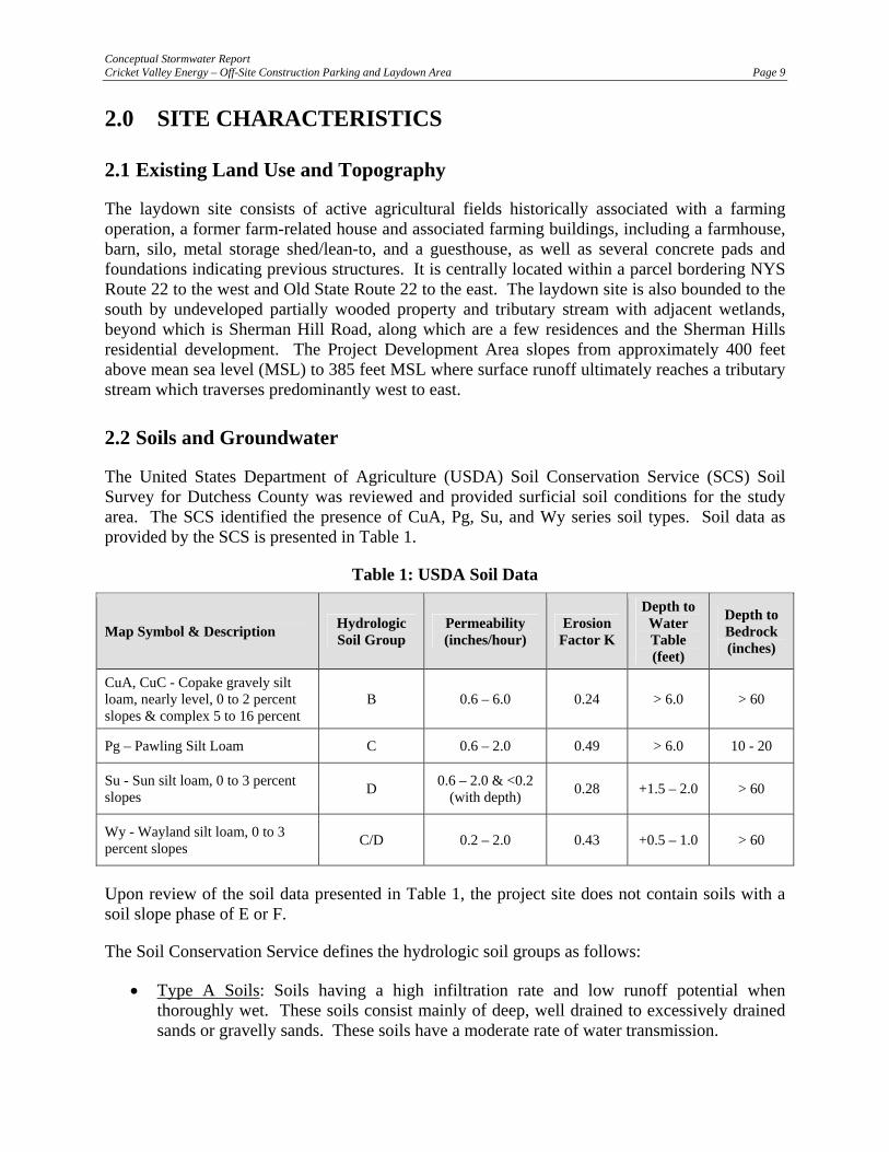
The United States Department of Agriculture (USDA) Soil Conservation Service (SCS) Soil Survey for Dutchess County was reviewed and provided surficial soil conditions for the study area. The SCS identified the presence of CuA, Pg, Su, and Wy series soil types. Soil data as provided by the SCS is presented in Table 1.
Table 1: USDA Soil Data
Map Symbol & Description Hydrologic Soil Group
Permeability (inches/hour)
Erosion Factor K
Depth to Water Table (feet)
Depth to Bedrock (inches)
CuA, CuC - Copake gravely silt loam, nearly level, 0 to 2 percent slopes & complex 5 to 16 percent
B 0.6 – 6.0 0.24 > 6.0 > 60
Pg – Pawling Silt Loam C 0.6 – 2.0 0.49 > 6.0 10 - 20
Su - Sun silt loam, 0 to 3 percent slopes D 0.6 – 2.0 & <0.2
(with depth) 0.28 +1.5 – 2.0 > 60
Wy - Wayland silt loam, 0 to 3 percent slopes C/D 0.2 – 2.0 0.43 +0.5 – 1.0 > 60
Upon review of the soil data presented in Table 1, the project site does not contain soils with a soil slope phase of E or F.
The Soil Conservation Service defines the hydrologic soil groups as follows:
• Type A Soils: Soils having a high infiltration rate and low runoff potential when thoroughly wet. These soils consist mainly of deep, well drained to excessively drained sands or gravelly sands. These soils have a moderate rate of water transmission.
Conceptual Stormwater Report Cricket Valley Energy – Off-Site Construction Parking and Laydown Area Page 10
• Type B Soils: Soils having a moderate infiltration rate when thoroughly wet and consisting mainly of moderately deep to deep, moderately well to well drained soils with moderately fine to moderately course textures. These soils have a moderate rate of water transmission.
• Type C Soils: Soils having a low infiltration rate when thoroughly wet and consisting chiefly of soils with a layer that impedes downward movement of water and soils with moderately fine-to-fine texture. These soils have a low rate of water transmission.
• Type D Soils: Soils having a very low infiltration rate and high runoff potential when thoroughly wet. These soils consist chiefly of clays that have high shrink-swell potential, soils that have a permanent high water table, soils that have a clay pan or clay layer at or near the surface, and soils that are shallow over nearly impervious material. These soils have a very low rate of water transmission.
A soils map for the study area and the watershed area is presented in Appendix A, as Figure 2.
2.3 Watershed Designation
Because the laydown site is not located in a restricted watershed identified in Appendix C of GP-0-10-001, enhanced phosphorous removal standards not are required.
Because this type of project is included in Table 2 of Appendix B of GP-0-10-001; and not located within an enhanced phosphorous removal watershed, the SWPPP will only need to include post-construction storm water management practices as well as erosion and sediment controls.
2.4 Receiving Water Bodies
Runoff from the project site will be discharged to a tributary stream with adjacent forested wetlands, and eventually conveyed to the Ten Mile River.
The tributary stream and Ten Mile River is classified by NYSDEC as a Class C (T) water course, and is not included in the Section 303(d) list of impaired waters found in Appendix E of GP-0-10-001. Impaired waters are identified as by the NYSDEC as waters that do not support appropriate uses and require the development of a Total Maximum Daily Load (TMDL) or other strategy to reduce the input of the specific pollutant(s) that restrict water uses; in order to restore and protect such uses.
2.5 Rainfall Data
Rainfall data utilized in the modeling and analysis were interpolated from maps presented in Chapter 4 of the NYSDEC Stormwater Management Design Manual, and in the National Weather Service (NWS) Technical Paper 40 (TP-40), Rainfall Frequency Atlas of the United States for Durations from 30 minutes to 24 Hours and Return Periods from 1 to 100 Years (1961). Rainfall data specific to the portion of Dutchess County under consideration, for various 24-hour storm events, is presented in Table 2:

Conceptual Stormwater Report Cricket Valley Energy – Off-Site Construction Parking and Laydown Area Page 11
Table 2: Rainfall Data
Storm Event Return Period
24-Hour Rainfall(inches)
1-year 2.8
10-year 5.0
100-year 8.0
These values were used to evaluate the pre- and post-development stormwater runoff characteristics for the analysis presented herein.
Conceptual Stormwater Report Cricket Valley Energy – Off-Site Construction Parking and Laydown Area Page 12
3.0 EROSION AND SEDIMENT CONTROL OVERVIEW
Temporary and permanent erosion and sediment control measures shall be implemented during construction, to minimize soil erosion and control sediment transport off-site, and after construction, to control the quality and quantity of stormwater runoff from the developed site.
The SWPPP will need to identify the temporary and permanent erosion and sediment control measures that will be incorporated into the final design of this project. The SWPPP will also need to outline the construction scheduling for implementing the erosion and sediment control measures; and will include limitations on the duration of soil exposure, criteria and specifications for placement and installation of the erosion and sediment control measures, a maintenance schedule, and specifications for the implementation of erosion and sediment control practices and procedures.
The following sections identifies the minimum temporary and permanent erosion and sediment control structures that shall be applied during the construction; maintenance procedures of each measure; and site assessments to take place relating to the proper implementation of the appropriate erosion and sediment control measures. These measures will be further detailed and designed during the preparation of the SWPPP.
3.1 Temporary Erosion and Sediment Control Measures
3.1.1 Stabilized Construction Entrance
Prior to construction, stabilized construction entrances shall be installed at points of entry and egress from the site to reduce the tracking of sediment onto public roadways.
Construction traffic must enter and exit the site at the stabilized construction entrance. The intent is to trap dust and mud that would otherwise be carried off-site by construction traffic.
The entrance shall be maintained in a condition, which will control tracking of sediment onto public rights-of-way or streets. When necessary, the placement of additional aggregate atop the filter fabric will be done to assure the minimum thickness is maintained. All sediments and soils spilled, dropped, or washed onto the public rights-of-way must be removed immediately. Periodic inspection and needed maintenance shall be provided after each substantial rainfall event.
3.1.2 Dust Control
Water trucks shall be used as needed during construction to reduce dust generated on the site. Dust control must be provided by the general Contractor to a degree that is acceptable to the Owner, and in compliance with the applicable local and state dust control requirements.
3.1.3 Temporary Soil Stockpile
Materials, such as topsoil, shall be temporarily stockpiled (if necessary) on the site during the construction process. Stockpiles shall be located in an area away from storm drainage, water
Conceptual Stormwater Report Cricket Valley Energy – Off-Site Construction Parking and Laydown Area Page 13
bodies and/or courses, and will be properly protected from erosion by a surrounding silt fence barrier.
3.1.4 Silt Fencing
Prior to the initiation of and during construction activities, a geotextile filter fabric (or silt fence) shall be established along the down slope perimeter of areas to be disturbed as a result of the construction which lie up gradient of watercourses or adjacent properties. These barriers may extend into non-impact areas to provide adequate protection of adjacent lands.
Clearing and grubbing shall be performed only as necessary for the installation of the sediment control barrier. To facilitate effectiveness of the silt fencing, daily inspections and inspections immediately after significant storm events shall be performed by site personnel. Maintenance of the fence shall be performed as needed.
3.1.5 Temporary Seeding
Areas undergoing clearing or grading and any areas disturbed by construction activities where work has temporarily or permanently ceased shall be stabilized with temporary vegetative cover within seven days from the date the soil disturbance activity ceased. The soil stabilization measures selected shall be in conformance with the New York State Standards and Specifications For Erosion and Sediment Control.
3.1.6 Stone Inlet Protection Barrier
Concrete blocks surrounded by wire mesh and crushed stone shall be placed around and proposed catch basins within areas of pavement once they have been installed, to keep sediment from entering the catch basins and storm sewer system. During construction, crushed stone shall be replaced as necessary to ensure proper function of the structure.
3.1.7 Erosion Control Blanket
Erosion control blankets (jute mesh) shall be installed on top of topsoil and seed within slopes between 15% and 30% slopes to provide temporary erosion protection while the vegetation is establishing on the adjacent slopes. Erosion control blankets provide temporary erosion protection, rapid vegetative establishment, and long-term erosion resistance to shear stresses associated with high runoff flow velocities associated with steep slopes. The blankets shall then be unrolled to maintain direct contact with the soil and anchored to the slope in accordance with the manufacturer’s instructions.
3.1.8 Stone Check Dams
Stone check dams shall be installed within temporary diversion swales to reduce the velocity of stormwater runoff, to promote settling of sediment, and to reduce sediment transport offsite.
Sediment accumulated behind the stone check dam shall be removed as needed to allow the channel to drain through the stone check dam and prevent large flows from carrying sediment over or around the dam. Stones shall be replaced as needed to maintain the design cross section of the structures.

Conceptual Stormwater Report Cricket Valley Energy – Off-Site Construction Parking and Laydown Area Page 14
3.1.9 Temporary Sediment Trap
Temporary sediment traps shall be incorporated into erosion and sediment control plan to intercept sediment-laden runoff and allow it to settle out of the surface runoff prior to being discharged from the site. Temporary sediment traps shall be constructed to intercept sediment-laden runoff and reduce the amount of sediment leaving the disturbed areas and to protect drainage ways, properties, and rights-of-way.
Accumulated sediment shall be removed from the trap when it reaches 50 percent of the design capacity and shall not exceed 50 percent. Sediment shall not be placed downstream from the embankment, adjacent to a stream, or floodplain.
Temporary sediment traps shall be designed to provide 3,600 cf. of storage per acre of tributary watershed. Based upon an anticipated disturbance of 25 acres, there is a potential need for a maximum 90,000 cf. of storage within several sediment traps during the course of construction. This is ultimately dependent upon the location of the sediment traps and the ability to divert runoff from non-disturbed areas.
3.1.10 Temporary Diversion Swales
Temporary diversion swales shall be used to divert off-site runoff around the construction site, divert runoff from stabilized areas around disturbed areas, and direct runoff from disturbed areas into sediment traps.
3.1.11 Dewatering Operations
Dewatering shall be used to intercept sediment-laden stormwater or pumped groundwater and allow it to settle out of the pumped discharge prior to being discharged from the site. Water from dewatering operations shall be treated to eliminate the discharge of sediment and other pollutants. Water resulting from dewatering operations shall be directed to the temporary sediment traps, or dewatering devices, such as the Dandy Dewatering Bag, manufactured by Mirafic Geosynthetics. Temporary sediment traps and dewatering bags shall be provided, installed and maintained at down-gradient locations to control sediment deposits to the wetlands.
3.2 Permanent Erosion and Sediment Control Measures
3.2.1 Establishment of Permanent Vegetation
All areas at final grade must be seeded and mulched within 14 days after completion of the major construction activity. All seeded areas should be protected with mulch.
Final site stabilization is achieved when all soil-disturbing activities at the site have been completed and a uniform, perennial vegetative cover with a density of 80 percent has been established or equivalent stabilization measures (such as the use of mulches or geotextiles) have been employed on all unpaved areas and areas not covered by permanent structures.

Conceptual Stormwater Report Cricket Valley Energy – Off-Site Construction Parking and Laydown Area Page 15
3.2.2 Rock Outlet Protection
Rock outlet protection shall be placed at the outlet end of the culverts or channels. The installation of rock outlet protection shall reduce the depth, velocity, and energy of water, such that the flow will not erode the receiving watercourse or water body.
3.2.3 Permanent Turf Reinforcement
Permanent turf reinforcement mats (TRMs) provide long-term erosion protection and vegetation establishment assistance while permanently reinforcing vegetation. TRMs shall be installed on all slopes exceeding 30%. TRM’s provide two key advantages. First, their unique fiber shape and 3-D pattern create a thick matrix of voids that trap seed, soil and water in place for quicker, thicker vegetation growth. Secondly, they provide additional reinforcement that doubles your vegetation’s natural erosion protection abilities by remaining a permanent part of the application, anchoring mature plants to the soil for superior, long-term erosion resistance.
3.3 Inspections, Maintenance, and Reporting
3.3.1 Pre-Construction Inspection and Certification
Prior to the commencement of construction, a Qualified Inspector in erosion and sediment control, shall conduct an assessment of the site and certify that the appropriate erosion and sediment control measures have been adequately installed and implemented.
3.3.2 Construction Phase Inspections and Maintenance
A Qualified Inspector shall conduct regular site inspections between the time the Final SWPPP is implemented and final site stabilization. Because it is likely that this project will involve a disturbance of greater than five acres of soil at any one time, site inspections will occur at an interval of at least twice every seven calendar days, with the inspections separated by a minimum of at least two full calendar days.
The purpose of site inspections is to assess performance of pollutant controls. Based on these inspections, the Qualified Inspector will decide whether it is necessary to modify the SWPPP, add or relocate sediment barriers, or whatever else may be needed in order to prevent pollutants from leaving the site via stormwater runoff.
3.3.3 Temporary Suspension of Construction Activities
For constructions sites where soil disturbance activities have been temporarily suspended (e.g. Winter shutdown) and temporary stabilization measures have been applied to all disturbed areas, the frequency of Qualified Inspector inspections can be reduced to once every 30 calendar days.
3.3.4 Partial Project Completion
For constructions sites where soil disturbance activities have been shut down with partial project completion, all areas disturbed as of the project shutdown date have achieved final stabilization, and all post-construction stormwater management practices required for the completed portion of
Conceptual Stormwater Report Cricket Valley Energy – Off-Site Construction Parking and Laydown Area Page 16
the project have been constructed in conformance with the SWPPP and are operational, the Qualified Inspector inspections can stop.
If soil disturbance activities have not resumed within two years from the date of shutdown, a NOT shall be properly completed and submitted to the NYSDEC.
3.3.5 Post-Construction Inspections and Maintenance
Regular scheduled inspections and maintenance of post-construction stormwater management practices shall be performed when all disturbed areas are stabilized and all stormwater management systems are in place and operable.
Conceptual Stormwater Report Cricket Valley Energy – Off-Site Construction Parking and Laydown Area Page 17
4.0 POST-CONSTRUCTION STORMWATER OVERVIEW
The goals of this Conceptual Stormwater Report are to analyze the peak rate of runoff under pre- and post-development conditions, determine preliminary maximum storage volume associated with each design storm, and calculate anticipated water quality volumes. Since a detailed design for the off-site construction parking and laydown area has not been developed, an estimated area of 20 acres of impervious material (gravel) and 25 acres of disturbance has been used for the purposes of establishing these initial design parameters.
4.1 Pre-Development Conditions
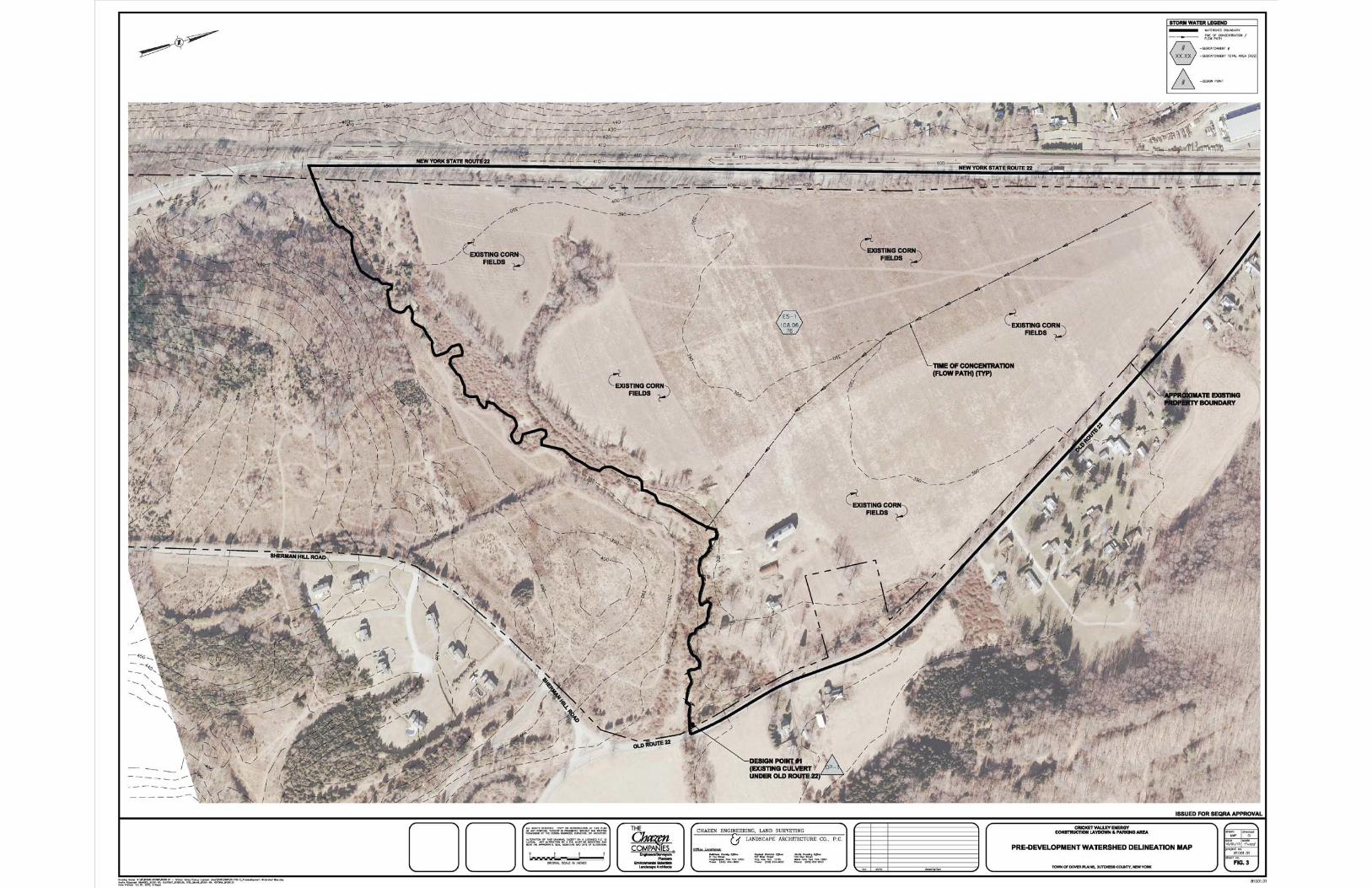
Subcatchment 1S is largely comprised of corn fields with scattered woods/grass areas to its south, east and western sections. The west and east side of the subcatchment is bordered by a NYS Route 22 and Old Route 22. Also found within the southeastern portion of the subcatchment are farm dwellings. The watershed associated with the subcatchment flows overland via sheet and shallow concentrated flow to an unnamed tributary stream that traverses the southern portion of the parcel. The tributary conveys the runoff from the project area in a westerly direction toward a culvert beneath Old Route 22 (Design Point #1).
A Pre-Development Watershed Delineation Map has been provided in Appendix B as Figure 3. The analysis of pre-development conditions considered existing drainage patterns, soil types, ground cover, and topography.
The results of the computer modeling used to analyze the overall watershed under pre-development conditions are presented in Appendix C.
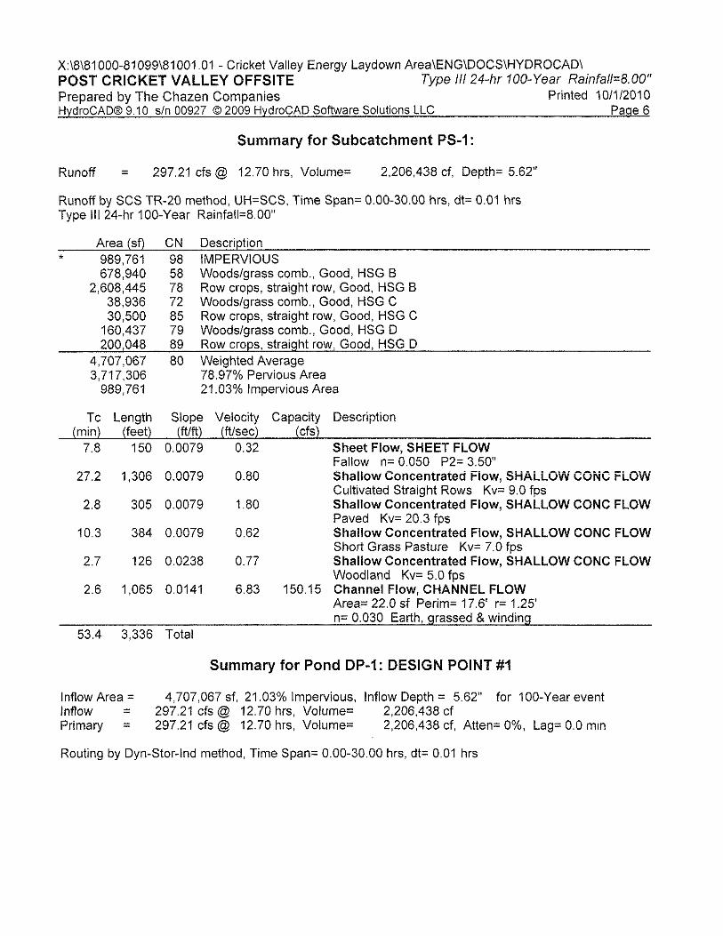
4.2 Post-Development Conditions
Under post development conditions, corn fields will be replaced with gravel areas used for construction parking and laydown areas, and stormwater management facilities. Existing drainage patterns will be maintained.
The Post-Development Watershed Delineation Map has been provided in Appendix A as Figure 4.
The results of the computer modeling used to analyze the overall watershed under post-development conditions are presented in Appendix C.
4.3 Stormwater Quantity Analysis
4.3.1 NYSDEC Requirements
The NYS Stormwater Management Design Manual requires that projects meet three separate stormwater quantity criteria:
1. The Channel Protection (CPv) requirement is designed to protect stream channels from erosion. This is accomplished by providing 24 hours of extended detention for the 1-

Conceptual Stormwater Report Cricket Valley Energy – Off-Site Construction Parking and Laydown Area Page 18
year, 24-hour storm event. The Design Manual defines the CPv detention time as the center of mass detention time through each stormwater management practice. For trout streams, the extended detention requirement is relaxed to 12 hours.
2. The Overbank Flood Control (Qp) requirement is designed to prevent an increase in the frequency and magnitude of flow events that exceed the bank-full capacity of a channel, and therefore must spill over into the floodplain. This is accomplished by providing detention storage to ensure that, at each design point, the post-development 10-year 24-hour peak discharge rate does not exceed the corresponding pre-development rate.
3. The Extreme Flood Control (Qf) requirement is designed to prevent the increased risk of flood damage from large storm events, to maintain the boundaries of the pre-development 100-year floodplain, and to protect the physical integrity of stormwater management practices. This is accomplished by providing detention storage to ensure that, at each design point, the post-development 100-year 24-hour peak discharge rate does not exceed the corresponding pre-development rate.
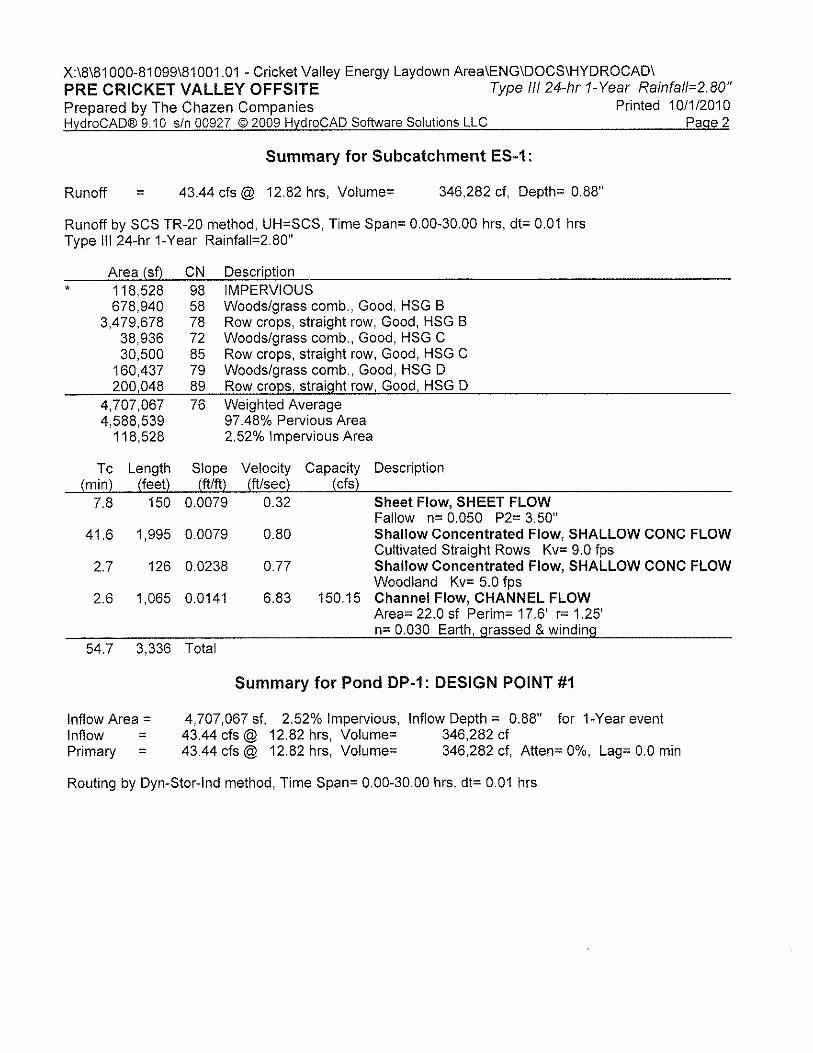
4.3.2 Methodology
In order to demonstrate that detention storage requirements are being met, the NYS Stormwater Management Design Manual requires that a hydrologic and hydraulic analysis of the pre- and post-development conditions be performed using the Natural Resources Conservation Service Technical Release 20 (TR-20) and Technical Release 55 (TR-55) methodologies. HydroCAD, developed by HydroCAD Software Solutions LLC of Tamworth, New Hampshire, is a Computer-Aided-Design (CAD) program for analyzing the hydrologic and hydraulic characteristics of a given watershed and associated stormwater management facilities. HydroCAD uses the TR-20 algorithms and TR-55 methods to create and route runoff hydrographs.
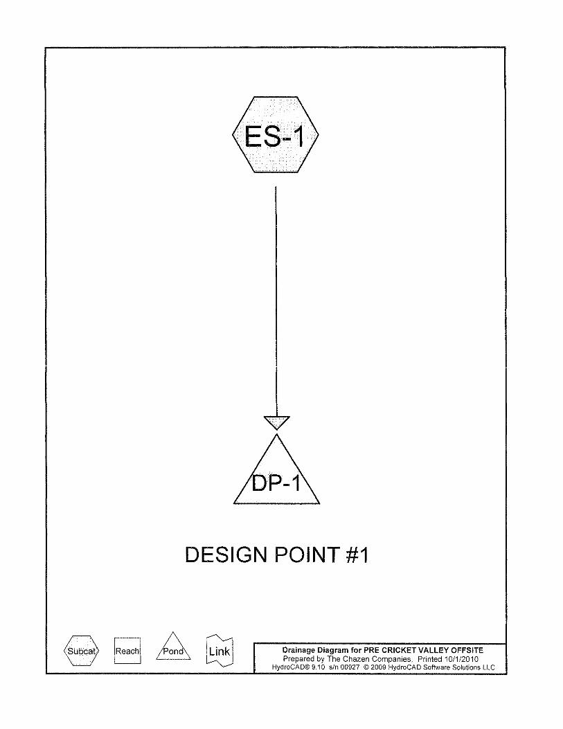
4.3.3 Description of Design Points
The preliminary hydrologic evaluation for this project focuses on locations where collected stormwater leaves the site, identified as Design Points (DP). The design theory is to provide a system that reduces post-development peak discharge rates to values less than or equal to pre-development peak discharge rates at each DP.
. Descriptions of each of the selected design points are provided below.
• Design Point 1: Existing culvert beneath Old Route 22.
4.3.4 Performance Summary
A comparison of the pre- and post-development watershed conditions was performed for all design points and storm events evaluated herein. This conceptual stormwater analysis has considered the SCS Type III, 24-hour, 1, 10, and 100-year storm events to determine the preliminary maximum storage volume that may be required to attenuate the runoff volume generated. The analysis considered only the proposed development area with respect to the watershed mappings. It is assumed at this conceptual design stage the watershed areas outside

Conceptual Stormwater Report Cricket Valley Energy – Off-Site Construction Parking and Laydown Area Page 19
development area will be diverted or managed without impact to the development areas. For all design points and design storms, this comparison portrays the post-development flow rate without attenuation and approximate detention volume necessary to reduce the peak rate of runoff to conditions less than pre-development.
The results of the computer modeling used to analyze the pre- and post-development watersheds are presented in Appendix B and Appendix C, respectively. Table 3 summarizes the results of this analysis.
Table 3: Summary of Pre- and Post-Development Peak Discharge Rates and Detention Requirements
Preliminary Pre- vs. Post-Development Discharge Rate (cfs) and Detention Requirements
Design Point 1-year 24-hour storm event 10-year 24-hour storm event 100-year 24-hour storm event
(DP) Pre (cfs)
Post (cfs)
Required Storage
(cf) Pre (cfs) Post (cfs)
Required Storage
(cf) Pre (cfs) Post (cfs)
Required Storage
(cf) 1 43.44 57.36 312,012* 132.78 154.51 211,069 270.95 297.21 352,633
* Includes volume necessary to provide 24-hours of extended detention
4.4 Stormwater Quality Analysis
Stormwater runoff from impervious surfaces is recognized as a significant contributor of pollution that can adversely affect the quality of receiving water bodies. Therefore, treatment of stormwater runoff is important since most runoff related water quality contaminants are transported from land, particularly the impervious surfaces, during the initial stages of storm events.
4.4.1 NYSDEC Requirements
The NYS Stormwater Management Design Manual requires that water quality treatment be provided for the initial flush of runoff from every storm. The NYSDEC refers to the amount of runoff to be treated as the “Water Quality Volume” (WQv). Section 4.2 of the Manual defines the Water Quality Volume as follows:
WQv = ( )( )( )[ ]
12ARP V
Where: P = 90% Rainfall Event Number Rv = 0.05 + 0.009 (I), minimum Rv = 0.2 I = Impervious Cover (Percent) A = Contributing Area in Acres
This definition ensures that, all other things being equal, the Water Quality Volume will increase along with the impervious cover percentage.
Conceptual Stormwater Report Cricket Valley Energy – Off-Site Construction Parking and Laydown Area Page 20
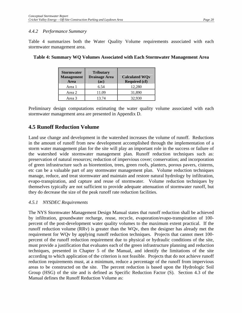
4.4.2 Performance Summary
Table 4 summarizes both the Water Quality Volume requirements associated with each stormwater management area.
Table 4: Summary WQ Volumes Associated with Each Stormwater Management Area
Stormwater Management
Area
Tributary Drainage Area
(ac) Calculated WQv
Required (cf) Area 1 6.54 12,280 Area 2 11.09 31,890 Area 3 13.74 32,930
Preliminary design computations estimating the water quality volume associated with each stormwater management area are presented in Appendix D.
4.5 Runoff Reduction Volume
Land use change and development in the watershed increases the volume of runoff. Reductions in the amount of runoff from new development accomplished through the implementation of a storm water management plan for the site will play an important role in the success or failure of the watershed wide stormwater management plan. Runoff reduction techniques such as: preservation of natural resources; reduction of impervious cover; conservation; and incorporation of green infrastructure such as bioretention, trees, green roofs, planters, porous pavers, cisterns, etc can be a valuable part of any stormwater management plan. Volume reduction techniques manage, reduce, and treat stormwater and maintain and restore natural hydrology by infiltration, evapo-transpiration, and capture and reuse of stormwater. Volume reduction techniques by themselves typically are not sufficient to provide adequate attenuation of stormwater runoff, but they do decrease the size of the peak runoff rate reduction facilities.
4.5.1 NYSDEC Requirements
The NYS Stormwater Management Design Manual states that runoff reduction shall be achieved by infiltration, groundwater recharge, reuse, recycle, evaporation/evapo-transpiration of 100-percent of the post-development water quality volumes to the maximum extent practical. If the runoff reduction volume (RRv) is greater than the WQv, then the designer has already met the requirement for WQv by applying runoff reduction techniques. Projects that cannot meet 100-percent of the runoff reduction requirement due to physical or hydraulic conditions of the site, must provide a justification that evaluates each of the green infrastructure planning and reduction techniques, presented in Chapter 5 of the Manual, and identify the limitations of the site according to which application of the criterion is not feasible. Projects that do not achieve runoff reduction requirements must, at a minimum, reduce a percentage of the runoff from impervious areas to be constructed on the site. The percent reduction is based upon the Hydrologic Soil Group (HSG) of the site and is defined as Specific Reduction Factor (S). Section 4.3 of the Manual defines the Runoff Reduction Volume as:

Conceptual Stormwater Report Cricket Valley Energy – Off-Site Construction Parking and Laydown Area Page 21
RRv = ( )( )( )[ ]12
Ai*RvP
Where: RRv = Runoff Reduction Volume (in acre-feet) P = 90% Rainfall Event Number Ai = Measured impervious cover targeted for infiltration. Ai = (S)(A) Rv* = 0.05+0.009(I) I = Impervious Cover (Percent) = 100% S = Hydrologic Soil Group (HSG) Specific Reduction Factor where:
HSG A = 0.55 HSG C = 0.30 HSG B = 0.40 HSG D = 0.20
Those projects not meeting 100-percent runoff reduction, are subject to the minimum RRV, and must incorporate stormwater management practices to address water quality treatment. Performance Summary
4.6 Stormwater Control Practices
In order to mitigate the potential discharge rate and qualitative treatment impacts associated with the proposed laydown site, a number of best management practices (BMP’s) can be included in the project to achieve compliance with Town and NYSDEC standards. Each BMP by itself may not provide major benefits, but becomes very effective when combined with others. The following practices may be considered in the proposed development: A detailed analysis of these practices must be completed, and the design of each practice must be prepared as part of the SWPPP.
4.6.1 Micropool Extended Detention Pond
The micropool extended detention pond is an effective means of removing pollutants and will provide a high pollutant removal rate for stormwater runoff. According to the NYSDEC publication Reducing the Impacts of Stormwater Runoff from New Development, high pollutant removal from extended detention ponds is primarily attributed to the permanent pool of water that provides gravity settling of sediment, chemical flocculation and biological uptake of pollutants.
Sediment forebays will capture sediment and floatable trash/debris prior to entering the pond. The pond is landscaped with a variety of plantings including emergents and woody shrubs, with each type of planting corresponding to the water depth. An aquatic bench will maximize the biological uptake of pollutants.
Micropool extended detention ponds provide attenuation and treatment of the runoff.
Conceptual Stormwater Report Cricket Valley Energy – Off-Site Construction Parking and Laydown Area Page 22
4.6.2 Pocket Pond
Wet ponds typically consist of two general components - a forebay and a permanent wet pool. The forebay provides pretreatment by capturing coarse sediment particles in order to minimize the need to remove the sediments from the primary wet pool. The wet pool serves as the primary treatment mechanism and where much of the retention capacity exists. Wet ponds can be sized for a wide range of watershed sizes, if adequate space exists
A variation of the conventional wet pond is as a pocket pond. The term “pocket” refers to a pond or wetland that has such a small contributing drainage area (between one to five acres) that little or no base flow is available to sustain water elevations during dry weather. Instead, water elevations are heavily influenced, and in some cases maintained, by a locally high water table. Because of these smaller drainage areas and the resulting lower hydraulic loads of pocket ponds, outlet structures can be simplified and often do not have safety features such as emergency spillways and low level drains.
Pocket ponds can be used to attenuate the peak flow and provide quality treatment by sedimentation, chemical flocculation, and biological removal. Sediment forebays will capture sediment and floatable trash/debris prior to entering the pond. The pocket pond is landscaped with a variety of plantings including emergents and woody shrubs, with each type of planting corresponding to the water depth. An aquatic bench will maximize the biological uptake of pollutants.
Pocket pond provides attenuation and treatment of the runoff.
4.6.3 Infiltration Basin
Infiltration practices reduce runoff volume, remove fine sediment and associated pollutants, recharge groundwater, and provide partial attenuation of peak flows for storm events equal to or less than the design storm.
Infiltration basins are stormwater impoundments designed to capture and infiltrate the water quality volume over several days, but do not retain a permanent pool. Infiltration basins can be designed as off-line devices to infiltrate the water quality volume and bypass larger flows to downstream flood control facilities or as combined infiltration/flood control facilities by providing detention above the infiltration zone. The bottom of an infiltration basin typically contains vegetation to increase the infiltration capacity of the basin, allow for vegetative uptake, and reduce soil erosion and scouring of the basin.
Based upon the County Soils mapping, the on-site soils are conducive for the use of infiltration basins.
Infiltration basins provide attenuation, treatment and reduction of the runoff.
4.6.4 Bioretention Areas
Bioretention systems are shallow landscaped depressions adapted to treat stormwater runoff on the developed site. These depressions are design to incorporate many of the pollutant removal mechanisms that operate in forested ecosystems. Stormwater flows into the bioretention area,

Conceptual Stormwater Report Cricket Valley Energy – Off-Site Construction Parking and Laydown Area Page 23
ponds above the mulch and soil, and gradually infiltrated into the soil bed. Pollutants are removed by a number of processes, such as adsorption, filtration, volatilization, ion exchange, and decomposition. Filtered runoff will infiltrate into the surrounding soil, functioning as an infiltration basin or rainwater garden.
Based upon the County Soils mapping, the on-site soils are conducive for the use of bioretention areas.
Bioretention areas provide treatment and reduction of the runoff.
4.6.5 Dry Swales
Dry swales are designed to temporarily hold the water quality volume of a storm in a pool or series of pools created by permanent check dams at culverts or access way crossings. The soil bed consists of native soils or highly permeable fill material, underlain by an under drain system. Pollutants are removed through sedimentation, nutrient uptake, and infiltration.
Dry swales provide treatment and reduction of the runoff.
4.6.6 Pre-treatment Areas
The NYS Design Manual requires that stormwater enter a pre-treatment device/area to provide filtering/sedimentation of coarse materials before entering a BMP. Pre-treatment devices/areas assist in the trapping of incoming sediment and taking up of nutrients prior to reaching the BMP.
When providing pre-treatment prior to a bio-retention area, facilities shall be provided to capture 40% of the water quality volume.
When providing pre-treatment prior to stormwater management basins and dry swales, facilities shall be provided to capture 10% of the water quality volume.
When providing pre-treatment prior to an infiltration basin, facilities shall be sized to handle 25% (where percolation rate is less than 2 inches per hour or 50% (where percolation rate is greater than 2 inches per hour) or 100% (where percolation rate is greater than 5 inches per hour) to capture 40% of the water quality volume.
Typically each pre-treatment facility consists of a minimum 4-foot deep plunge pool or forebay formed by an earth barrier and equipped with a trapezoidal weir to convey storm water to the treatment practice. Trapezoidal weirs are stabilized with rip rap to prevent erosion to the earth beam.
4.7 Soil Testing
Invasive testing will be required to confirm adequate depth to groundwater and bedrock and/or the underlying soils are suitable for the proposed practice.

Conceptual Stormwater Report Cricket Valley Energy – Off-Site Construction Parking and Laydown Area Page 24
Test pits have to be conducted to the bottom elevation of a stormwater management basin to confirm the bottom of the practice lies below groundwater. Should this not be the case, a liner (clay or polyethylene, etc.) would be required to sustain a permanent pool of water.
Test pits have to be conducted to a minimum depth of 2-feet below the bottom elevation of bio-retention areas, and open channels; and 4-feet beneath of the bottom of infiltration to confirm adequate separation to groundwater and/or groundwater.
Test pits have to be conducted to a minimum depth of 4-feet below the bottom elevation of infiltration facilities to confirm adequate separation to groundwater.
Percolation tests shall be performed to determine the hydraulic conductivity of the underlying soils when designing infiltration and bioretention areas. A minimum of 1 percolation tests shall be performed for every 200-square feet of area.

Conceptual Stormwater Report Cricket Valley Energy – Off-Site Construction Parking and Laydown Area Page 25
5.0 CONCLUSION
Development will impact stormwater discharge rates and quality. Preliminary stormwater discharge rates and quality calculations are provided at the current conceptual phase of the project, but a detailed evaluation will have to be completed after the proposed laydown area is more definitive.
Based on the conceptual plan and the discussion above, stormwater impacts and erosion and sediment control measures will need to be evaluated; mitigative measures will need to be designed; and regulatory approvals will need to be obtained.
Best managements practices as described within Section 4 of this document can be integrated into the site plan in order to minimize qualitative impacts of the stormwater runoff and manage the peak rate of runoff.
Approvals related to storm water management design will include a SWPPP by the NYSDEC and the Town Engineer.


Æ·22
Old State R
oute 22
Sh
e rma n
Hi ll R
d
On i o ntow
n R
d
Lee s Ln
Gra
n t Dr
Sm i th R
d
Ben so n Ln
0 1,500 3,000750
Feet
1 inch = 750 feet
Date:
Scale:
Project:
Figure:
Drawn:SCP
09/30/2010
81001.00
1
Cricket Valley Energy Off-Site Construction Parking and Laydown Area
Figure 1: Site Location Map (Ortho Photo)Town of Dover, Dutchess County, New York
Map Document: (X:\8\81000-81099\81001 - Cricket Vallet Energy\GIS\maps\SWP3\Cricket Vally_81001.00_Fig 1 Site Location 8X11.mxd)9/30/2010 -- 7:01:55 PM
ENGINEERS/SURVEYORSPLANNERS
ENVIRONMENTAL SCIENTISTSLANDSCAPE ARCHITECTS
Capital District Office:547 River Street, Troy, NY 12180Phone: (518) 273-0055
Glens Falls Office:100 Glen Street, Glens Falls, NY 12801Phone: (518) 812-0513
Dutchess County Office:21 Fox Street, Poughkeepsie, NY 12601Phone: (845) 454-3980
.
Source: 2009 Ortho Photo Images for Town of Dover, Town of Dover 2009 Tax Parcel Data; State of New York DOT 2008 Roads dataset.
Project Site
LegendParking & Laydown Area
Project Parcel
Other Parcels


HoF
Pg
CuA
FeE
Su
Pg
FcD
HoD
CtC
SkC
CuB
FeE
FcC
CrE
CuA
CuC
PsSmC
CuB
CuD
CuA
CuA
GsB
MnB
Wy
CuA
SmC
CuC
CuA
Ps
CuC
CuC
SkD
We
Æ·22
Old State R
oute 22
She
rman
Hil
l R
d
On i o ntow
n R
d
Lee s Ln
Gra
n t Dr
Sm i th R
d
Ben so n Ln
0 1,500 3,000750
Feet
1 inch = 750 feet
Date:
Scale:
Project:
Figure:
Drawn:SCP
09/30/2010
81001.00
2
Cricket Valley Energy Off-Site Construction Parking and Laydown Area
Figure 2: Soils MapTown of Dover, Dutchess County, New York
Map Document: (X:\8\81000-81099\81001 - Cricket Vallet Energy\GIS\maps\SWP3\Cricket Vally_81001.00_Fig 2 Soils Map 8X11.mxd)9/30/2010 -- 7:03:36 PM
ENGINEERS/SURVEYORSPLANNERS
ENVIRONMENTAL SCIENTISTSLANDSCAPE ARCHITECTS
Capital District Office:547 River Street, Troy, NY 12180Phone: (518) 273-0055
Glens Falls Office:100 Glen Street, Glens Falls, NY 12801Phone: (518) 812-0513
Dutchess County Office:21 Fox Street, Poughkeepsie, NY 12601Phone: (845) 454-3980
.
Source: 2004 Soil Survey for Dutchess County, Town of Dover 2009 Tax Parcel Data; State of New York DOT 2008 Roads dataset.
Project Site
LegendParking & Laydown Area
Project Parcel
Other Parcels