Embed Size (px)
Citation preview

Kent County Drain Commissioner Stormwater Standards Manual Rev. 11.23.2020
Appendix B
BMP Design Criteria for Stormwater Controls
Table of Contents – Appendix B
Kent County Drain Commissioner Stormwater Standards Manual Rev. 11.23.2020
i
I. Non-Structural Best Management Practices ....................................................................................................1 A. Minimal Disturbance Area .........................................................................................................................2 B. Protect Natural Flow Pathways ..................................................................................................................3 C. Protect Sensitive Areas ..............................................................................................................................4 D. Native Revegetation ...................................................................................................................................5 E. Stormwater Disconnect..............................................................................................................................6
II. Structural Best Management Practices ............................................................................................................7 A. Storm Sewer ...............................................................................................................................................8 B. Culvert or Bridge ..................................................................................................................................... 11 C. Open Channel .......................................................................................................................................... 12 D. Detention Basins ..................................................................................................................................... 14 E. Retention Basins...................................................................................................................................... 23 F. Infiltration Practices ................................................................................................................................ 29 G. Bioretention/Rain Garden ....................................................................................................................... 35 H. Constructed Filter .................................................................................................................................... 39 I. Planter Box .............................................................................................................................................. 42 J. Pervious Pavement.................................................................................................................................. 45 K. Capture Reuse ......................................................................................................................................... 48 L. Vegetated Roof ....................................................................................................................................... 50 M. Water Quality Device .............................................................................................................................. 51 N. Sediment Forebay ................................................................................................................................... 52 O. Spill Containment Cell ............................................................................................................................. 53 P. Bioswale and Water Quality Swale ......................................................................................................... 56 Q. Vegetated Swale...................................................................................................................................... 61 R. Vegetated Filter Strip .............................................................................................................................. 63 S. Level Spreader ......................................................................................................................................... 68
List of Tables
Table 12 – Manning’s Roughness Coefficients ...........................................................................................................9 Table 13 – Minimum and Maximum Slopes for Storm Sewers ..................................................................................9 Table 14 –Hydraulic Conductivities for Filter Media ............................................................................................... 40 Table 15 – Permanent Stabilization Treatment for Vegetated Swales ................................................................... 62
List of Figures
Figure 3 – Manning’s Roughness Coefficients for Vegetated Swales ...................................................................... 61 Figure 4a – Filter Strip Length (Sandy soils with HSG A) ......................................................................................... 65 Figure 4b1 – Filter Strip Length (Sandy Loam soils with HSG B) .............................................................................. 65 Figure 4b2 – Filter Strip Length (Loam, Silt-Loam soils with HSG B) ....................................................................... 65 Figure 4c – Filter Strip Length (Sandy Clay Loam soils with HSG C) ........................................................................ 66 Figure 4d – Filter Strip Length (Clay Loam, Silty Clay, Clay soils with HSG D) ......................................................... 66
APPENDIX B– BMP DESIGN CRITERIA
Kent County Drain Commissioner 1 Stormwater Standards Manual Rev. 11.23.2020
I. NON-STRUCTURAL BEST MANAGEMENT PRACTICES Non-structural BMPs consist of protection measures that reduce the volume of stormwater runoff from the site. This differs from the goal of many structural BMPs which is to help mitigate the impact of stormwater runoff.
Design criteria is provided for the following non-structural BMPs:
A. Minimal Disturbance Area B. Protect Natural Flow Pathways C. Protect Sensitive Areas D. Native Revegetation E. Stormwater Disconnect
Further information and examples are provided in the BMP Fact Sheets in Chapter 6 of the Low Impact Development Manual for Michigan (SEMCOG, 2008):
All of the following criteria must be met to receive credit for each non-structural BMP selected for use.
APPENDIX B– BMP DESIGN CRITERIA
Kent County Drain Commissioner 2 Stormwater Standards Manual Rev. 11.23.2020
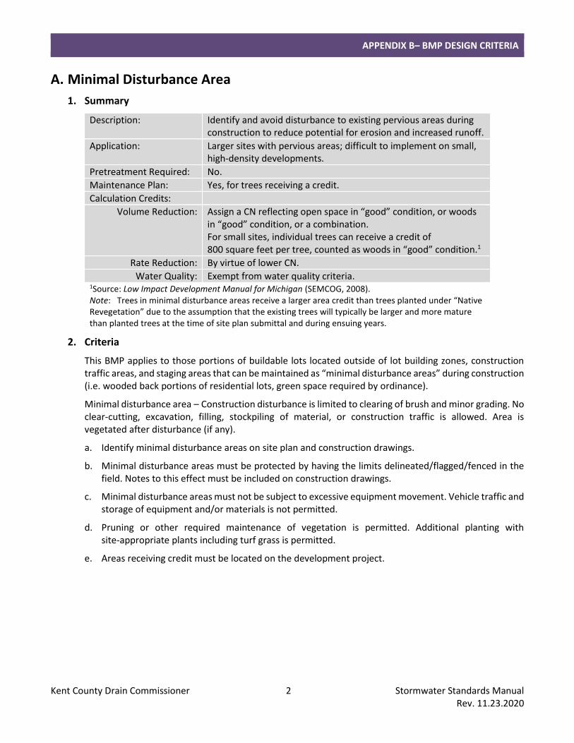
A. Minimal Disturbance Area
1. Summary
Description: Identify and avoid disturbance to existing pervious areas during construction to reduce potential for erosion and increased runoff.
Application: Larger sites with pervious areas; difficult to implement on small, high-density developments.
Pretreatment Required: No.
Maintenance Plan: Yes, for trees receiving a credit.
Calculation Credits:
Volume Reduction: Assign a CN reflecting open space in “good” condition, or woods in “good” condition, or a combination. For small sites, individual trees can receive a credit of 800 square feet per tree, counted as woods in “good” condition.1
Rate Reduction: By virtue of lower CN.
Water Quality: Exempt from water quality criteria. 1Source: Low Impact Development Manual for Michigan (SEMCOG, 2008). Note: Trees in minimal disturbance areas receive a larger area credit than trees planted under “Native Revegetation” due to the assumption that the existing trees will typically be larger and more mature than planted trees at the time of site plan submittal and during ensuing years.
2. Criteria
This BMP applies to those portions of buildable lots located outside of lot building zones, construction traffic areas, and staging areas that can be maintained as “minimal disturbance areas” during construction (i.e. wooded back portions of residential lots, green space required by ordinance).
Minimal disturbance area – Construction disturbance is limited to clearing of brush and minor grading. No clear-cutting, excavation, filling, stockpiling of material, or construction traffic is allowed. Area is vegetated after disturbance (if any).
a. Identify minimal disturbance areas on site plan and construction drawings.
b. Minimal disturbance areas must be protected by having the limits delineated/flagged/fenced in the field. Notes to this effect must be included on construction drawings.
c. Minimal disturbance areas must not be subject to excessive equipment movement. Vehicle traffic and storage of equipment and/or materials is not permitted.
d. Pruning or other required maintenance of vegetation is permitted. Additional planting with site-appropriate plants including turf grass is permitted.
e. Areas receiving credit must be located on the development project.
APPENDIX B– BMP DESIGN CRITERIA
Kent County Drain Commissioner 3 Stormwater Standards Manual Rev. 11.23.2020
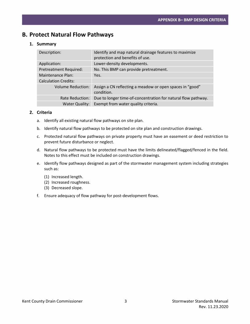
B. Protect Natural Flow Pathways
1. Summary
Description: Identify and map natural drainage features to maximize protection and benefits of use.
Application: Lower-density developments.
Pretreatment Required: No. This BMP can provide pretreatment.
Maintenance Plan: Yes.
Calculation Credits:
Volume Reduction: Assign a CN reflecting a meadow or open spaces in “good” condition.
Rate Reduction: Due to longer time-of-concentration for natural flow pathway.
Water Quality: Exempt from water quality criteria.
2. Criteria
a. Identify all existing natural flow pathways on site plan.
b. Identify natural flow pathways to be protected on site plan and construction drawings.
c. Protected natural flow pathways on private property must have an easement or deed restriction to prevent future disturbance or neglect.
d. Natural flow pathways to be protected must have the limits delineated/flagged/fenced in the field. Notes to this effect must be included on construction drawings.
e. Identify flow pathways designed as part of the stormwater management system including strategies such as:
(1) Increased length. (2) Increased roughness. (3) Decreased slope.
f. Ensure adequacy of flow pathway for post-development flows.
APPENDIX B– BMP DESIGN CRITERIA
Kent County Drain Commissioner 4 Stormwater Standards Manual Rev. 11.23.2020
C. Protect Sensitive Areas
1. Summary
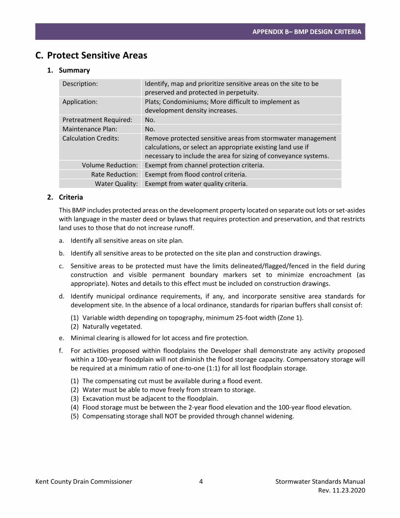
Description: Identify, map and prioritize sensitive areas on the site to be preserved and protected in perpetuity.
Application: Plats; Condominiums; More difficult to implement as development density increases.
Pretreatment Required: No.
Maintenance Plan: No.
Calculation Credits: Remove protected sensitive areas from stormwater management calculations, or select an appropriate existing land use if necessary to include the area for sizing of conveyance systems.
Volume Reduction: Exempt from channel protection criteria.
Rate Reduction: Exempt from flood control criteria.
Water Quality: Exempt from water quality criteria.
2. Criteria
This BMP includes protected areas on the development property located on separate out lots or set-asides with language in the master deed or bylaws that requires protection and preservation, and that restricts land uses to those that do not increase runoff.
a. Identify all sensitive areas on site plan.
b. Identify all sensitive areas to be protected on the site plan and construction drawings.
c. Sensitive areas to be protected must have the limits delineated/flagged/fenced in the field during construction and visible permanent boundary markers set to minimize encroachment (as appropriate). Notes and details to this effect must be included on construction drawings.
d. Identify municipal ordinance requirements, if any, and incorporate sensitive area standards for development site. In the absence of a local ordinance, standards for riparian buffers shall consist of:
(1) Variable width depending on topography, minimum 25-foot width (Zone 1). (2) Naturally vegetated.
e. Minimal clearing is allowed for lot access and fire protection.
f. For activities proposed within floodplains the Developer shall demonstrate any activity proposed within a 100-year floodplain will not diminish the flood storage capacity. Compensatory storage will be required at a minimum ratio of one-to-one (1:1) for all lost floodplain storage.
(1) The compensating cut must be available during a flood event. (2) Water must be able to move freely from stream to storage. (3) Excavation must be adjacent to the floodplain. (4) Flood storage must be between the 2-year flood elevation and the 100-year flood elevation. (5) Compensating storage shall NOT be provided through channel widening.
APPENDIX B– BMP DESIGN CRITERIA
Kent County Drain Commissioner 5 Stormwater Standards Manual Rev. 11.23.2020
D. Native Revegetation
1. Summary
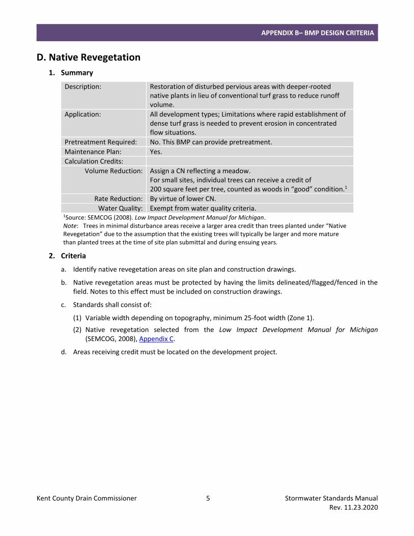
Description: Restoration of disturbed pervious areas with deeper-rooted native plants in lieu of conventional turf grass to reduce runoff volume.
Application: All development types; Limitations where rapid establishment of dense turf grass is needed to prevent erosion in concentrated flow situations.
Pretreatment Required: No. This BMP can provide pretreatment.
Maintenance Plan: Yes.
Calculation Credits:
Volume Reduction: Assign a CN reflecting a meadow. For small sites, individual trees can receive a credit of 200 square feet per tree, counted as woods in “good” condition.1
Rate Reduction: By virtue of lower CN.
Water Quality: Exempt from water quality criteria. 1Source: SEMCOG (2008). Low Impact Development Manual for Michigan. Note: Trees in minimal disturbance areas receive a larger area credit than trees planted under “Native Revegetation” due to the assumption that the existing trees will typically be larger and more mature than planted trees at the time of site plan submittal and during ensuing years.
2. Criteria
a. Identify native revegetation areas on site plan and construction drawings.
b. Native revegetation areas must be protected by having the limits delineated/flagged/fenced in the field. Notes to this effect must be included on construction drawings.
c. Standards shall consist of:
(1) Variable width depending on topography, minimum 25-foot width (Zone 1).
(2) Native revegetation selected from the Low Impact Development Manual for Michigan (SEMCOG, 2008), Appendix C.
d. Areas receiving credit must be located on the development project.
APPENDIX B– BMP DESIGN CRITERIA
Kent County Drain Commissioner 6 Stormwater Standards Manual Rev. 11.23.2020
E. Stormwater Disconnect
1. Summary
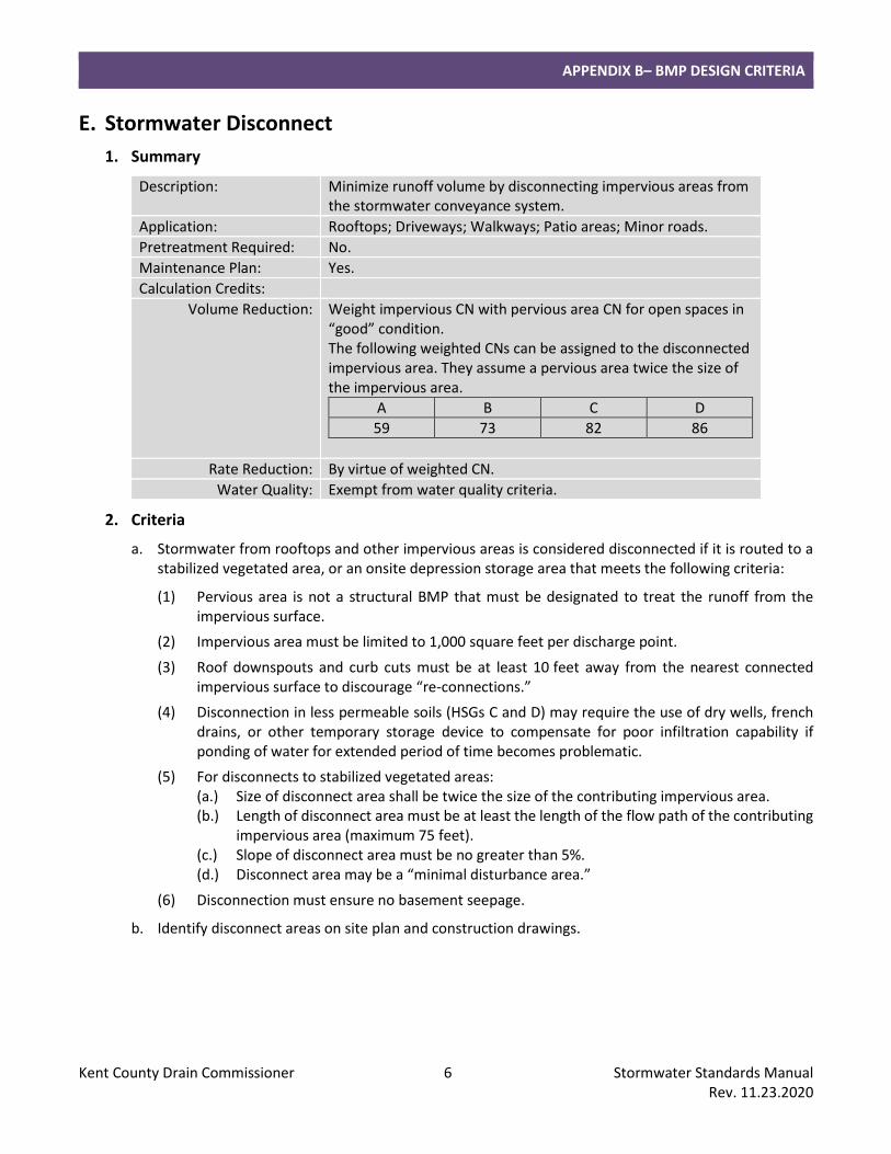
Description: Minimize runoff volume by disconnecting impervious areas from the stormwater conveyance system.
Application: Rooftops; Driveways; Walkways; Patio areas; Minor roads.
Pretreatment Required: No.
Maintenance Plan: Yes.
Calculation Credits:
Volume Reduction: Weight impervious CN with pervious area CN for open spaces in “good” condition. The following weighted CNs can be assigned to the disconnected impervious area. They assume a pervious area twice the size of the impervious area.
A B C D
59 73 82 86
Rate Reduction: By virtue of weighted CN.
Water Quality: Exempt from water quality criteria.
2. Criteria
a. Stormwater from rooftops and other impervious areas is considered disconnected if it is routed to a stabilized vegetated area, or an onsite depression storage area that meets the following criteria:
(1) Pervious area is not a structural BMP that must be designated to treat the runoff from the impervious surface.
(2) Impervious area must be limited to 1,000 square feet per discharge point.
(3) Roof downspouts and curb cuts must be at least 10 feet away from the nearest connected impervious surface to discourage “re-connections.”
(4) Disconnection in less permeable soils (HSGs C and D) may require the use of dry wells, french drains, or other temporary storage device to compensate for poor infiltration capability if ponding of water for extended period of time becomes problematic.
(5) For disconnects to stabilized vegetated areas: (a.) Size of disconnect area shall be twice the size of the contributing impervious area. (b.) Length of disconnect area must be at least the length of the flow path of the contributing
impervious area (maximum 75 feet). (c.) Slope of disconnect area must be no greater than 5%. (d.) Disconnect area may be a “minimal disturbance area.”
(6) Disconnection must ensure no basement seepage.
b. Identify disconnect areas on site plan and construction drawings.

APPENDIX B– BMP DESIGN CRITERIA
Kent County Drain Commissioner 7 Stormwater Standards Manual Rev. 11.23.2020
II. STRUCTURAL BEST MANAGEMENT PRACTICES Structural BMPs are constructed measures that convey, store and treat stormwater in a site-specific location and help mitigate the impact of stormwater runoff.
Design criteria is provided for the following structural BMPs:
Conveyance and Storage
A. Storm Sewer B. Culvert or Bridge C. Open Channel D. Detention Basins E. Retention Basins
LID and Small Site
F. Infiltration Practices G. Bioretention/Rain Garden H. Constructed Filter I. Planter Box J. Pervious Pavement K. Capture Reuse L. Vegetated Roof M. Water Quality Device N. Sediment Forebay O. Spill Containment Cell P. Bioswale and Water Quality Swale Q. Vegetated Swale R. Vegetated Filter Strip S. Level Spreader
BMPs shall be designed in accordance with these standards.
Further information and examples for LID and Small Site BMPs are provided in the BMP Fact Sheets in Chapter 7 the Low Impact Development Manual for Michigan (SEMCOG, 2008).
Note: Design criteria for BMPs used primarily for soil erosion and sedimentation control and channel stabilization (i.e. riprap, in-stream structures, natural channel design), and technical specifications for construction are beyond the scope of this manual.
APPENDIX B– BMP DESIGN CRITERIA
Kent County Drain Commissioner 8 Stormwater Standards Manual Rev. 11.23.2020
A. Storm Sewer
1. Summary
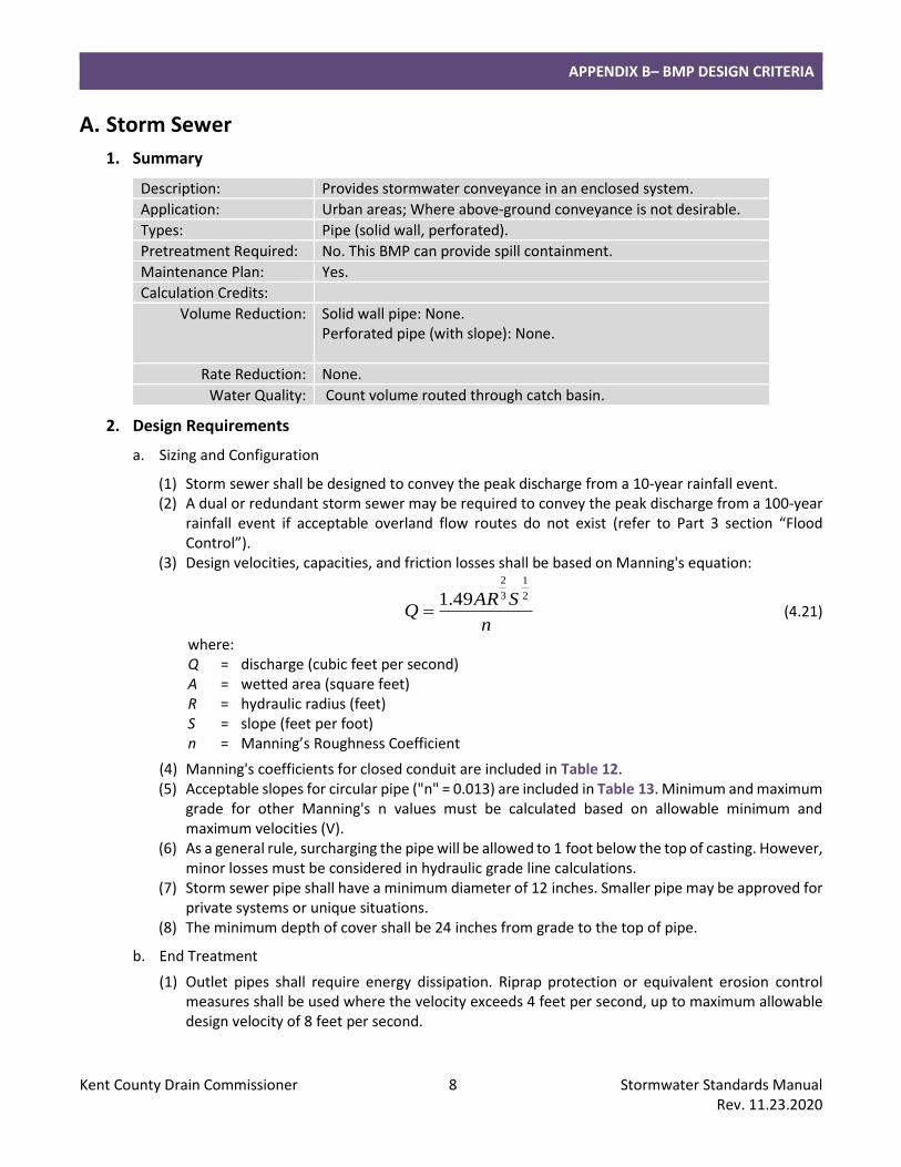
Description: Provides stormwater conveyance in an enclosed system.
Application: Urban areas; Where above-ground conveyance is not desirable.
Types: Pipe (solid wall, perforated).
Pretreatment Required: No. This BMP can provide spill containment.
Maintenance Plan: Yes.
Calculation Credits:
Volume Reduction: Solid wall pipe: None. Perforated pipe (with slope): None.
Rate Reduction: None.
Water Quality: Count volume routed through catch basin.
2. Design Requirements
a. Sizing and Configuration
(1) Storm sewer shall be designed to convey the peak discharge from a 10-year rainfall event. (2) A dual or redundant storm sewer may be required to convey the peak discharge from a 100-year
rainfall event if acceptable overland flow routes do not exist (refer to Part 3 section “Flood Control”).
(3) Design velocities, capacities, and friction losses shall be based on Manning's equation:
n
SARQ
2
1
3
2
49.1= (4.21)
where: Q = discharge (cubic feet per second) A = wetted area (square feet) R = hydraulic radius (feet) S = slope (feet per foot) n = Manning’s Roughness Coefficient
(4) Manning's coefficients for closed conduit are included in Table 12. (5) Acceptable slopes for circular pipe ("n" = 0.013) are included in Table 13. Minimum and maximum
grade for other Manning's n values must be calculated based on allowable minimum and maximum velocities (V).
(6) As a general rule, surcharging the pipe will be allowed to 1 foot below the top of casting. However, minor losses must be considered in hydraulic grade line calculations.
(7) Storm sewer pipe shall have a minimum diameter of 12 inches. Smaller pipe may be approved for private systems or unique situations.
(8) The minimum depth of cover shall be 24 inches from grade to the top of pipe.
b. End Treatment
(1) Outlet pipes shall require energy dissipation. Riprap protection or equivalent erosion control measures shall be used where the velocity exceeds 4 feet per second, up to maximum allowable design velocity of 8 feet per second.
APPENDIX B– BMP DESIGN CRITERIA
Kent County Drain Commissioner 9 Stormwater Standards Manual Rev. 11.23.2020
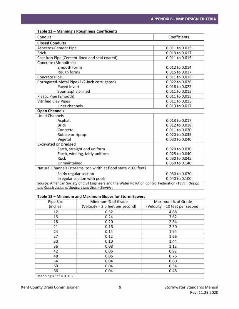
Table 12 – Manning’s Roughness Coefficients
Conduit Coefficients
Closed Conduits Asbestos-Cement Pipe 0.011 to 0.015 Brick 0.013 to 0.017 Cast Iron Pipe (Cement-lined and seal-coated) 0.011 to 0.015 Concrete (Monolithic) Smooth forms 0.012 to 0.014 Rough forms 0.015 to 0.017 Concrete Pipe 0.011 to 0.015 Corrugated-Metal Pipe (1/2-inch corrugated) 0.022 to 0.026 Paved invert 0.018 to 0.022 Spun asphalt-lined 0.011 to 0.015 Plastic Pipe (Smooth) 0.011 to 0.015 Vitrified Clay Pipes 0.011 to 0.015 Liner channels 0.013 to 0.017 Open Channels Lined Channels Asphalt 0.013 to 0.017 Brick 0.012 to 0.018 Concrete 0.011 to 0.020 Rubble or riprap 0.020 to 0.035 Vegetal 0.030 to 0.040 Excavated or Dredged Earth, straight and uniform 0.020 to 0.030 Earth, winding, fairly uniform 0.025 to 0.040 Rock 0.030 to 0.045 Unmaintained 0.050 to 0.140 Natural Channels (streams, top width at flood state <100 feet)
Fairly regular section 0.030 to 0.070 Irregular section with pools 0.040 to 0.100 Source: American Society of Civil Engineers and the Water Pollution Control Federation (1969). Design and Construction of Sanitary and Storm Sewers.
Table 13 – Minimum and Maximum Slopes for Storm Sewers Pipe Size (inches)
Minimum % of Grade (Velocity = 2.5 feet per second)
Maximum % of Grade (Velocity = 10 feet per second)
12 0.32 4.88 15 0.24 3.62 18 0.20 2.84 21 0.16 2.30 24 0.14 1.94 27 0.12 1.66 30 0.10 1.44 36 0.08 1.12 42 0.06 0.92 48 0.06 0.76 54 0.04 0.60 60 0.04 0.54 66 0.04 0.48
Manning’s “n” = 0.013
APPENDIX B– BMP DESIGN CRITERIA
Kent County Drain Commissioner 10 Stormwater Standards Manual Rev. 11.23.2020
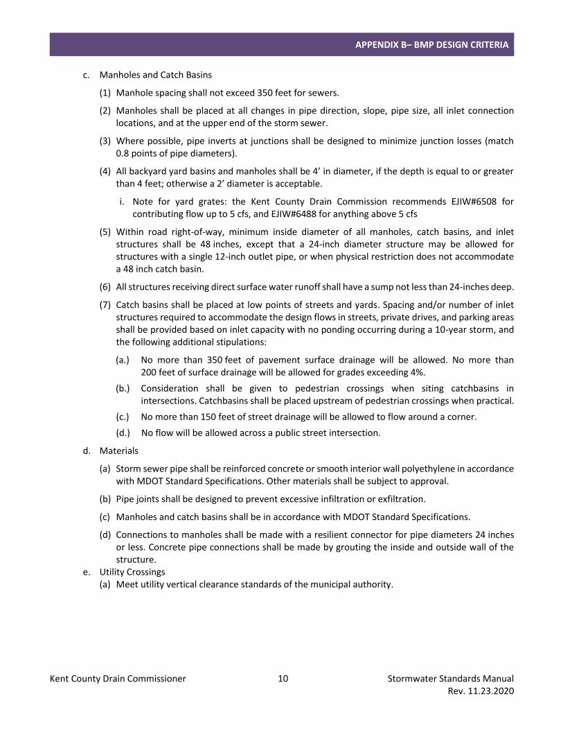
c. Manholes and Catch Basins
(1) Manhole spacing shall not exceed 350 feet for sewers.
(2) Manholes shall be placed at all changes in pipe direction, slope, pipe size, all inlet connection locations, and at the upper end of the storm sewer.
(3) Where possible, pipe inverts at junctions shall be designed to minimize junction losses (match 0.8 points of pipe diameters).
(4) All backyard yard basins and manholes shall be 4’ in diameter, if the depth is equal to or greater than 4 feet; otherwise a 2’ diameter is acceptable.
i. Note for yard grates: the Kent County Drain Commission recommends EJIW#6508 for contributing flow up to 5 cfs, and EJIW#6488 for anything above 5 cfs
(5) Within road right-of-way, minimum inside diameter of all manholes, catch basins, and inlet structures shall be 48 inches, except that a 24-inch diameter structure may be allowed for structures with a single 12-inch outlet pipe, or when physical restriction does not accommodate a 48 inch catch basin.
(6) All structures receiving direct surface water runoff shall have a sump not less than 24-inches deep.
(7) Catch basins shall be placed at low points of streets and yards. Spacing and/or number of inlet structures required to accommodate the design flows in streets, private drives, and parking areas shall be provided based on inlet capacity with no ponding occurring during a 10-year storm, and the following additional stipulations:
(a.) No more than 350 feet of pavement surface drainage will be allowed. No more than 200 feet of surface drainage will be allowed for grades exceeding 4%.
(b.) Consideration shall be given to pedestrian crossings when siting catchbasins in intersections. Catchbasins shall be placed upstream of pedestrian crossings when practical.
(c.) No more than 150 feet of street drainage will be allowed to flow around a corner.
(d.) No flow will be allowed across a public street intersection.
d. Materials
(a) Storm sewer pipe shall be reinforced concrete or smooth interior wall polyethylene in accordance with MDOT Standard Specifications. Other materials shall be subject to approval.
(b) Pipe joints shall be designed to prevent excessive infiltration or exfiltration.
(c) Manholes and catch basins shall be in accordance with MDOT Standard Specifications.
(d) Connections to manholes shall be made with a resilient connector for pipe diameters 24 inches or less. Concrete pipe connections shall be made by grouting the inside and outside wall of the structure.
e. Utility Crossings (a) Meet utility vertical clearance standards of the municipal authority.
APPENDIX B– BMP DESIGN CRITERIA
Kent County Drain Commissioner 11 Stormwater Standards Manual Rev. 11.23.2020
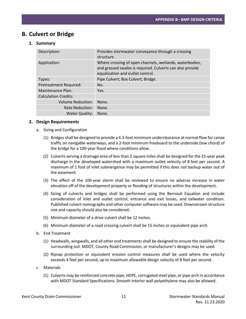
B. Culvert or Bridge
1. Summary
Description: Provides stormwater conveyance through a crossing structure.
Application: Where crossing of open channels, wetlands, waterbodies, and grassed swales is required. Culverts can also provide equalization and outlet control.
Types: Pipe Culvert; Box Culvert; Bridge.
Pretreatment Required: No.
Maintenance Plan: Yes.
Calculation Credits:
Volume Reduction: None.
Rate Reduction: None.
Water Quality: None.
2. Design Requirements
a. Sizing and Configuration
(1) Bridges shall be designed to provide a 4.3-foot minimum underclearance at normal flow for canoe traffic on navigable waterways, and a 2-foot minimum freeboard to the underside (low chord) of the bridge for a 100-year flood where conditions allow.
(2) Culverts serving a drainage area of less than 2 square miles shall be designed for the 25-year peak discharge in the developed watershed with a maximum outlet velocity of 8 feet per second. A maximum of 1 foot of inlet submergence may be permitted if this does not backup water out of the easement.
(3) The effect of the 100-year storm shall be reviewed to ensure no adverse increase in water elevation off of the development property or flooding of structures within the development.
(4) Sizing of culverts and bridges shall be performed using the Bernouli Equation and include consideration of inlet and outlet control, entrance and exit losses, and tailwater condition. Published culvert nomographs and other computer software may be used. Downstream structure size and capacity should also be considered.
(5) Minimum diameter of a drive culvert shall be 12 inches.
(6) Minimum diameter of a road crossing culvert shall be 15 inches or equivalent pipe arch.
b. End Treatment
(1) Headwalls, wingwalls, and all other end treatments shall be designed to ensure the stability of the surrounding soil. MDOT, County Road Commission, or manufacturer’s designs may be used.
(2) Riprap protection or equivalent erosion control measures shall be used where the velocity exceeds 4 feet per second, up to maximum allowable design velocity of 8 feet per second.
c. Materials
(1) Culverts may be reinforced concrete pipe, HDPE, corrugated steel pipe, or pipe arch in accordance with MDOT Standard Specifications. Smooth interior wall polyethylene may also be allowed.
APPENDIX B– BMP DESIGN CRITERIA
Kent County Drain Commissioner 12 Stormwater Standards Manual Rev. 11.23.2020
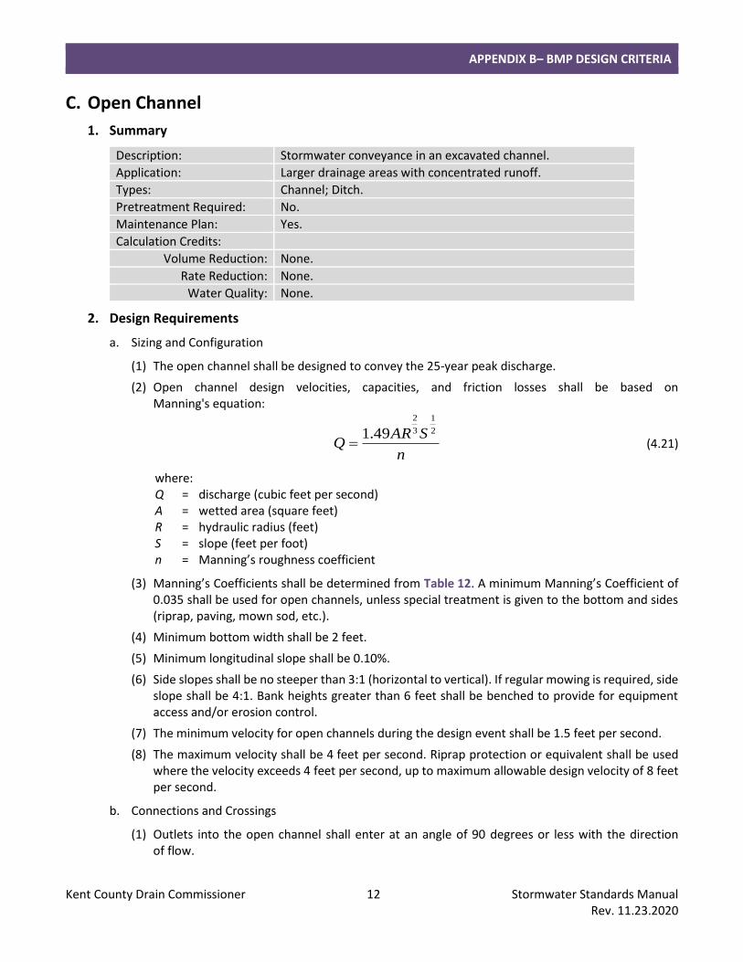
C. Open Channel
1. Summary
Description: Stormwater conveyance in an excavated channel.
Application: Larger drainage areas with concentrated runoff.
Types: Channel; Ditch.
Pretreatment Required: No.
Maintenance Plan: Yes.
Calculation Credits:
Volume Reduction: None.
Rate Reduction: None.
Water Quality: None.
2. Design Requirements
a. Sizing and Configuration
(1) The open channel shall be designed to convey the 25-year peak discharge.
(2) Open channel design velocities, capacities, and friction losses shall be based on Manning's equation:
n
SARQ
2
1
3
2
49.1= (4.21)
where: Q = discharge (cubic feet per second) A = wetted area (square feet) R = hydraulic radius (feet) S = slope (feet per foot) n = Manning’s roughness coefficient
(3) Manning’s Coefficients shall be determined from Table 12. A minimum Manning’s Coefficient of 0.035 shall be used for open channels, unless special treatment is given to the bottom and sides (riprap, paving, mown sod, etc.).
(4) Minimum bottom width shall be 2 feet.
(5) Minimum longitudinal slope shall be 0.10%.
(6) Side slopes shall be no steeper than 3:1 (horizontal to vertical). If regular mowing is required, side slope shall be 4:1. Bank heights greater than 6 feet shall be benched to provide for equipment access and/or erosion control.
(7) The minimum velocity for open channels during the design event shall be 1.5 feet per second.
(8) The maximum velocity shall be 4 feet per second. Riprap protection or equivalent shall be used where the velocity exceeds 4 feet per second, up to maximum allowable design velocity of 8 feet per second.
b. Connections and Crossings
(1) Outlets into the open channel shall enter at an angle of 90 degrees or less with the direction of flow.

APPENDIX B– BMP DESIGN CRITERIA
Kent County Drain Commissioner 13 Stormwater Standards Manual Rev. 11.23.2020
(2) A minimum clearance of 4 feet is required between open channel inverts and underground utilities unless special provisions are approved.
APPENDIX B– BMP DESIGN CRITERIA
Kent County Drain Commissioner 14 Stormwater Standards Manual Rev. 11.23.2020
D. Detention Basins
1. Summary
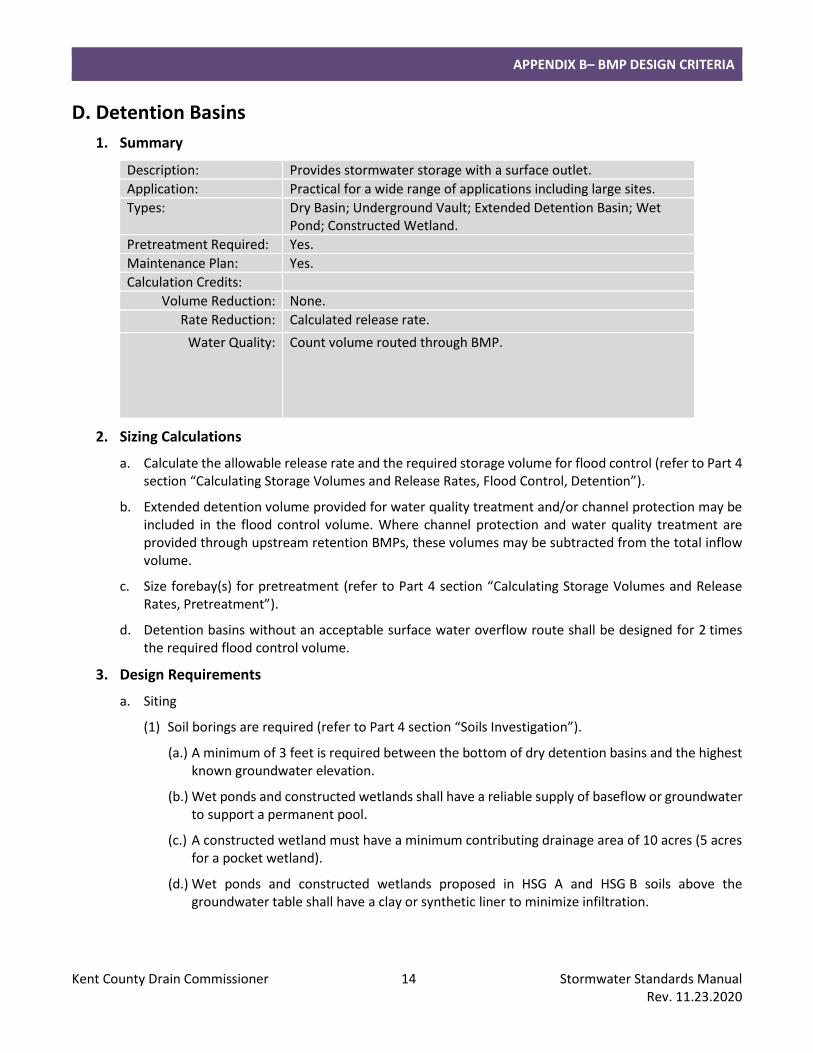
Description: Provides stormwater storage with a surface outlet.
Application: Practical for a wide range of applications including large sites.
Types: Dry Basin; Underground Vault; Extended Detention Basin; Wet Pond; Constructed Wetland.
Pretreatment Required: Yes.
Maintenance Plan: Yes.
Calculation Credits:
Volume Reduction: None.
Rate Reduction: Calculated release rate.
Water Quality: Count volume routed through BMP.
2. Sizing Calculations
a. Calculate the allowable release rate and the required storage volume for flood control (refer to Part 4 section “Calculating Storage Volumes and Release Rates, Flood Control, Detention”).
b. Extended detention volume provided for water quality treatment and/or channel protection may be included in the flood control volume. Where channel protection and water quality treatment are provided through upstream retention BMPs, these volumes may be subtracted from the total inflow volume.
c. Size forebay(s) for pretreatment (refer to Part 4 section “Calculating Storage Volumes and Release Rates, Pretreatment”).
d. Detention basins without an acceptable surface water overflow route shall be designed for 2 times the required flood control volume.
3. Design Requirements
a. Siting
(1) Soil borings are required (refer to Part 4 section “Soils Investigation”).
(a.) A minimum of 3 feet is required between the bottom of dry detention basins and the highest known groundwater elevation.
(b.) Wet ponds and constructed wetlands shall have a reliable supply of baseflow or groundwater to support a permanent pool.
(c.) A constructed wetland must have a minimum contributing drainage area of 10 acres (5 acres for a pocket wetland).
(d.) Wet ponds and constructed wetlands proposed in HSG A and HSG B soils above the groundwater table shall have a clay or synthetic liner to minimize infiltration.
APPENDIX B– BMP DESIGN CRITERIA
Kent County Drain Commissioner 15 Stormwater Standards Manual Rev. 11.23.2020
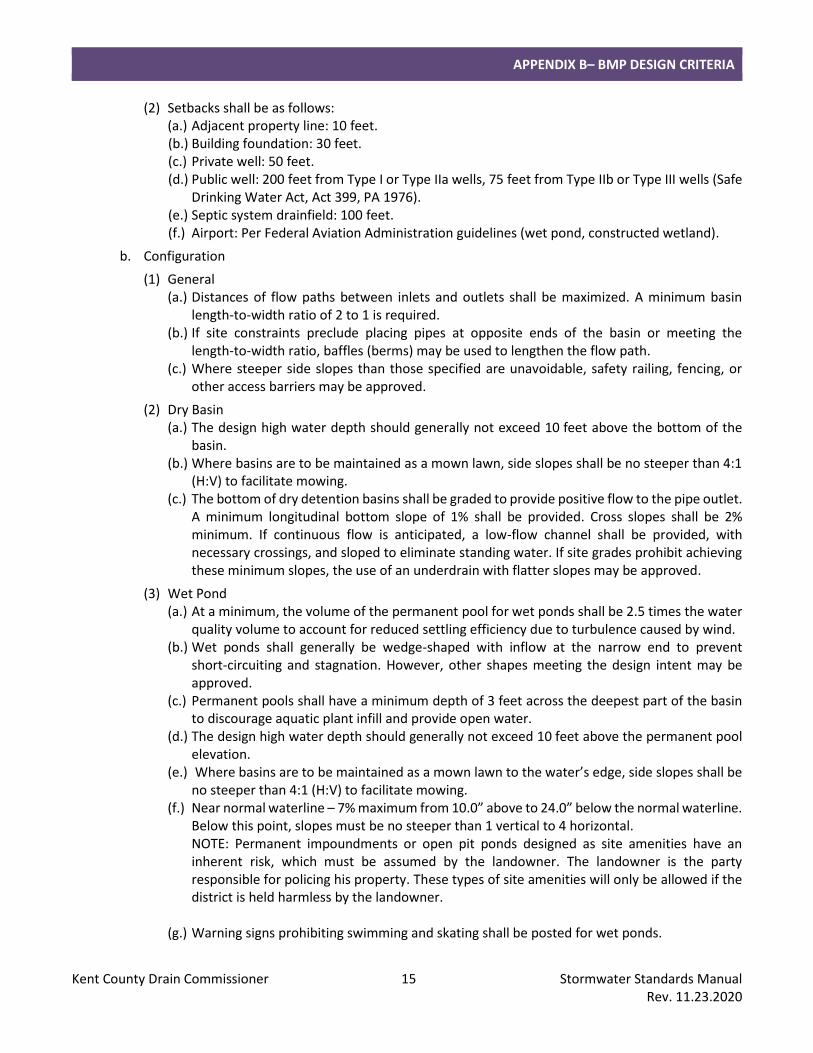
(2) Setbacks shall be as follows: (a.) Adjacent property line: 10 feet. (b.) Building foundation: 30 feet. (c.) Private well: 50 feet. (d.) Public well: 200 feet from Type I or Type IIa wells, 75 feet from Type IIb or Type III wells (Safe
Drinking Water Act, Act 399, PA 1976). (e.) Septic system drainfield: 100 feet. (f.) Airport: Per Federal Aviation Administration guidelines (wet pond, constructed wetland).
b. Configuration
(1) General (a.) Distances of flow paths between inlets and outlets shall be maximized. A minimum basin
length-to-width ratio of 2 to 1 is required. (b.) If site constraints preclude placing pipes at opposite ends of the basin or meeting the
length-to-width ratio, baffles (berms) may be used to lengthen the flow path. (c.) Where steeper side slopes than those specified are unavoidable, safety railing, fencing, or
other access barriers may be approved.
(2) Dry Basin (a.) The design high water depth should generally not exceed 10 feet above the bottom of the
basin. (b.) Where basins are to be maintained as a mown lawn, side slopes shall be no steeper than 4:1
(H:V) to facilitate mowing. (c.) The bottom of dry detention basins shall be graded to provide positive flow to the pipe outlet.
A minimum longitudinal bottom slope of 1% shall be provided. Cross slopes shall be 2% minimum. If continuous flow is anticipated, a low-flow channel shall be provided, with necessary crossings, and sloped to eliminate standing water. If site grades prohibit achieving these minimum slopes, the use of an underdrain with flatter slopes may be approved.
(3) Wet Pond (a.) At a minimum, the volume of the permanent pool for wet ponds shall be 2.5 times the water
quality volume to account for reduced settling efficiency due to turbulence caused by wind. (b.) Wet ponds shall generally be wedge-shaped with inflow at the narrow end to prevent
short-circuiting and stagnation. However, other shapes meeting the design intent may be approved.
(c.) Permanent pools shall have a minimum depth of 3 feet across the deepest part of the basin to discourage aquatic plant infill and provide open water.
(d.) The design high water depth should generally not exceed 10 feet above the permanent pool elevation.
(e.) Where basins are to be maintained as a mown lawn to the water’s edge, side slopes shall be no steeper than 4:1 (H:V) to facilitate mowing.
(f.) Near normal waterline – 7% maximum from 10.0” above to 24.0” below the normal waterline. Below this point, slopes must be no steeper than 1 vertical to 4 horizontal. NOTE: Permanent impoundments or open pit ponds designed as site amenities have an inherent risk, which must be assumed by the landowner. The landowner is the party responsible for policing his property. These types of site amenities will only be allowed if the district is held harmless by the landowner.
(g.) Warning signs prohibiting swimming and skating shall be posted for wet ponds.
APPENDIX B– BMP DESIGN CRITERIA
Kent County Drain Commissioner 16 Stormwater Standards Manual Rev. 11.23.2020
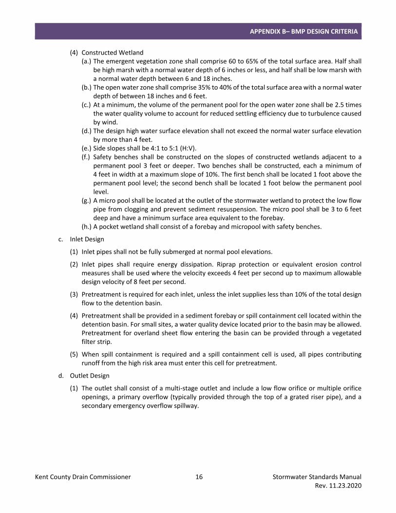
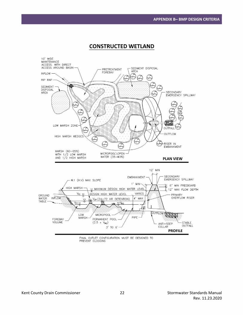
(4) Constructed Wetland (a.) The emergent vegetation zone shall comprise 60 to 65% of the total surface area. Half shall
be high marsh with a normal water depth of 6 inches or less, and half shall be low marsh with a normal water depth between 6 and 18 inches.
(b.) The open water zone shall comprise 35% to 40% of the total surface area with a normal water depth of between 18 inches and 6 feet.
(c.) At a minimum, the volume of the permanent pool for the open water zone shall be 2.5 times the water quality volume to account for reduced settling efficiency due to turbulence caused by wind.
(d.) The design high water surface elevation shall not exceed the normal water surface elevation by more than 4 feet.
(e.) Side slopes shall be 4:1 to 5:1 (H:V). (f.) Safety benches shall be constructed on the slopes of constructed wetlands adjacent to a
permanent pool 3 feet or deeper. Two benches shall be constructed, each a minimum of 4 feet in width at a maximum slope of 10%. The first bench shall be located 1 foot above the permanent pool level; the second bench shall be located 1 foot below the permanent pool level.
(g.) A micro pool shall be located at the outlet of the stormwater wetland to protect the low flow pipe from clogging and prevent sediment resuspension. The micro pool shall be 3 to 6 feet deep and have a minimum surface area equivalent to the forebay.
(h.) A pocket wetland shall consist of a forebay and micropool with safety benches.
c. Inlet Design
(1) Inlet pipes shall not be fully submerged at normal pool elevations.
(2) Inlet pipes shall require energy dissipation. Riprap protection or equivalent erosion control measures shall be used where the velocity exceeds 4 feet per second up to maximum allowable design velocity of 8 feet per second.
(3) Pretreatment is required for each inlet, unless the inlet supplies less than 10% of the total design flow to the detention basin.
(4) Pretreatment shall be provided in a sediment forebay or spill containment cell located within the detention basin. For small sites, a water quality device located prior to the basin may be allowed. Pretreatment for overland sheet flow entering the basin can be provided through a vegetated filter strip.
(5) When spill containment is required and a spill containment cell is used, all pipes contributing runoff from the high risk area must enter this cell for pretreatment.
d. Outlet Design
(1) The outlet shall consist of a multi-stage outlet and include a low flow orifice or multiple orifice openings, a primary overflow (typically provided through the top of a grated riser pipe), and a secondary emergency overflow spillway.
APPENDIX B– BMP DESIGN CRITERIA
Kent County Drain Commissioner 17 Stormwater Standards Manual Rev. 11.23.2020
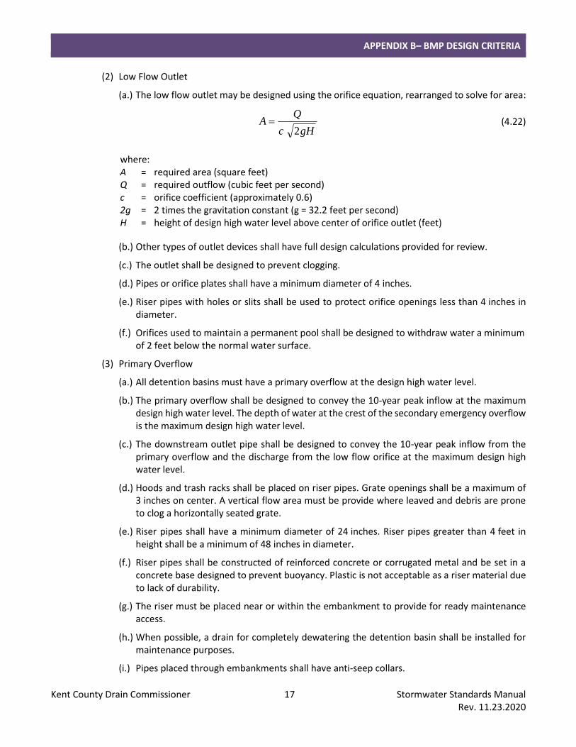
(2) Low Flow Outlet
(a.) The low flow outlet may be designed using the orifice equation, rearranged to solve for area:
gHc
QA
2= (4.22)
where: A = required area (square feet) Q = required outflow (cubic feet per second) c = orifice coefficient (approximately 0.6) 2g = 2 times the gravitation constant (g = 32.2 feet per second) H = height of design high water level above center of orifice outlet (feet)
(b.) Other types of outlet devices shall have full design calculations provided for review.
(c.) The outlet shall be designed to prevent clogging.
(d.) Pipes or orifice plates shall have a minimum diameter of 4 inches.
(e.) Riser pipes with holes or slits shall be used to protect orifice openings less than 4 inches in diameter.
(f.) Orifices used to maintain a permanent pool shall be designed to withdraw water a minimum of 2 feet below the normal water surface.
(3) Primary Overflow
(a.) All detention basins must have a primary overflow at the design high water level.
(b.) The primary overflow shall be designed to convey the 10-year peak inflow at the maximum design high water level. The depth of water at the crest of the secondary emergency overflow is the maximum design high water level.
(c.) The downstream outlet pipe shall be designed to convey the 10-year peak inflow from the primary overflow and the discharge from the low flow orifice at the maximum design high water level.
(d.) Hoods and trash racks shall be placed on riser pipes. Grate openings shall be a maximum of 3 inches on center. A vertical flow area must be provide where leaved and debris are prone to clog a horizontally seated grate.
(e.) Riser pipes shall have a minimum diameter of 24 inches. Riser pipes greater than 4 feet in height shall be a minimum of 48 inches in diameter.
(f.) Riser pipes shall be constructed of reinforced concrete or corrugated metal and be set in a concrete base designed to prevent buoyancy. Plastic is not acceptable as a riser material due to lack of durability.
(g.) The riser must be placed near or within the embankment to provide for ready maintenance access.
(h.) When possible, a drain for completely dewatering the detention basin shall be installed for maintenance purposes.
(i.) Pipes placed through embankments shall have anti-seep collars.
APPENDIX B– BMP DESIGN CRITERIA
Kent County Drain Commissioner 18 Stormwater Standards Manual Rev. 11.23.2020
(j.) Outlet pipes shall require energy dissipation. Riprap protection or equivalent erosion control measures shall be used where the velocity exceeds 4 feet per second up to maximum allowable design velocity of 8 feet per second.
(4) Secondary Emergency Overflow
(a.) All detention basins must have a provision for emergency overflow (i.e. a spillway).
(b.) The spillway shall be designed for the 10-year peak inflow with a maximum flow depth of 1 foot. The spillway shall be sized using the weir equation:
2
3
6.2 LHQ = (4.23)
where: Q = discharge (cubic feet per second) 2.6 = coefficient of discharge L = length of spillway crest (feet) H = total head measured above spillway crest (feet)
(c.) Freeboard. The top of berm elevation shall be a minimum of 0.5 foot above the design flow depth over the spillway. In no case shall the spillway depth (distance between spillway crest and top of berm) be less than 1 foot.
(d.) Overflow spillways shall be protected with concrete or turf reinforced with a three-dimensional root mat or geogrids, to prevent erosion of the structure. Protection shall extend across the entire spillway up to the top of berm, start on the basin side a minimum of 3 feet below the spillway crest and extend down the spillway to an apron a minimum of 6 feet beyond the toe of the spillway.
e. Access
(1) Outlet control structures shall be placed near or within the embankment to facilitate maintenance access.
(2) Berm top width shall be a minimum of 12 feet.
(3) A minimum 10-foot wide maintenance access route from a public or private right-of-way shall be provided to the basin. The access way shall have a vertical grade of no greater than 20% (5:1 H:V slope) and shall be stabilized to withstand the passage of heavy equipment. Direct access to the forebay, control structures and the outlet shall be provided.
APPENDIX B– BMP DESIGN CRITERIA
Kent County Drain Commissioner 19 Stormwater Standards Manual Rev. 11.23.2020
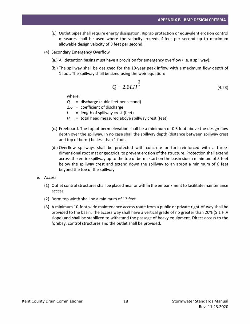
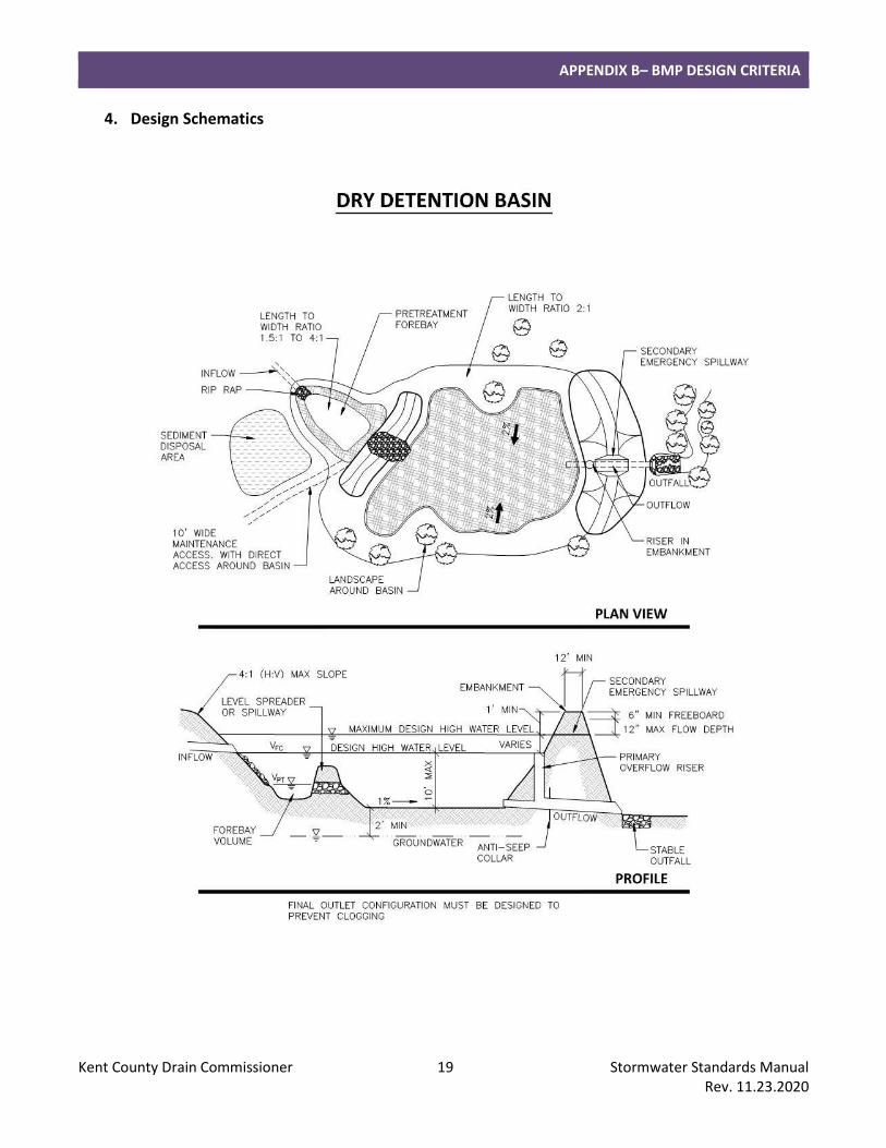
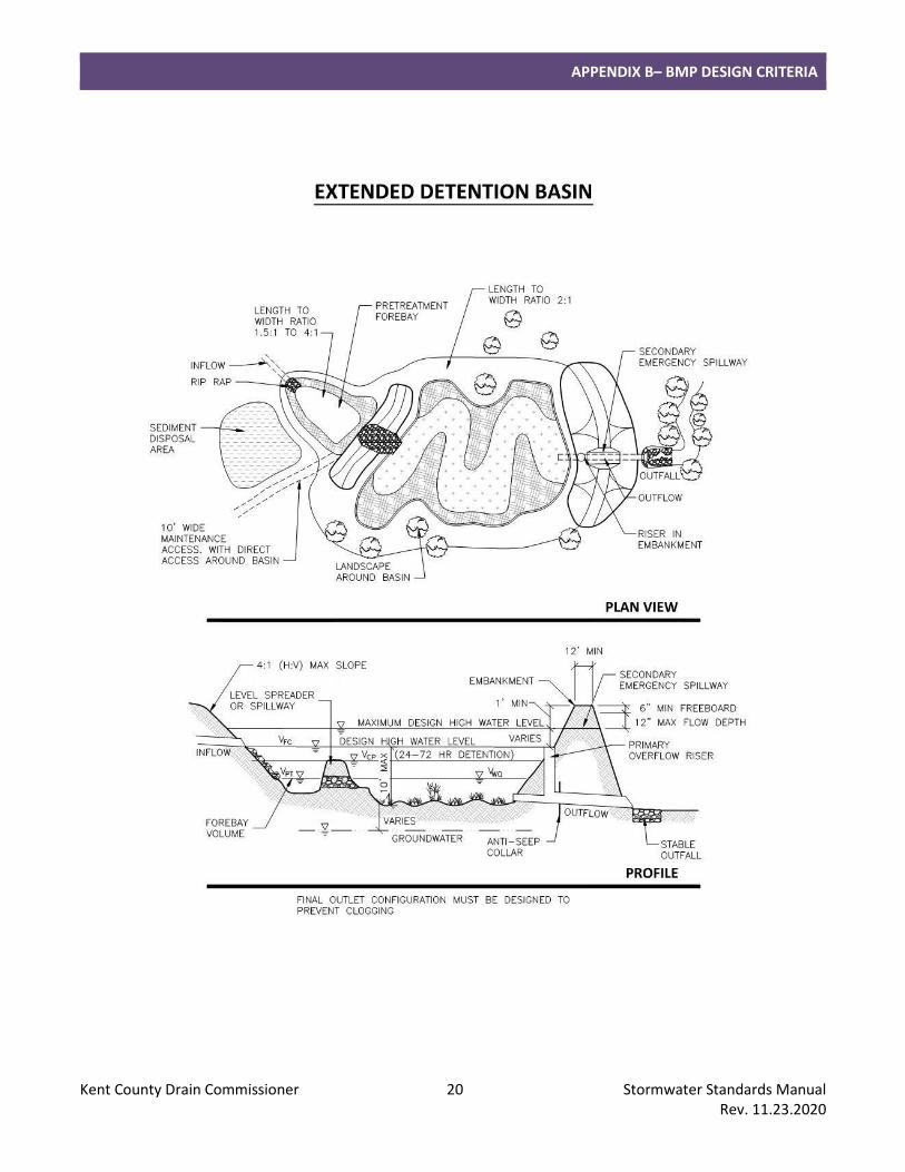
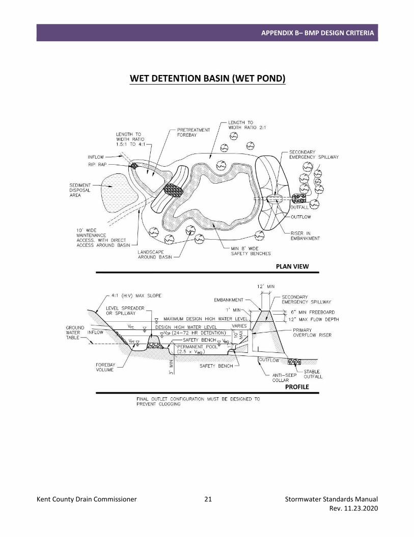
4. Design Schematics
APPENDIX B– BMP DESIGN CRITERIA
Kent County Drain Commissioner 20 Stormwater Standards Manual Rev. 11.23.2020
APPENDIX B– BMP DESIGN CRITERIA
Kent County Drain Commissioner 21 Stormwater Standards Manual Rev. 11.23.2020
APPENDIX B– BMP DESIGN CRITERIA
Kent County Drain Commissioner 22 Stormwater Standards Manual Rev. 11.23.2020
APPENDIX B– BMP DESIGN CRITERIA
Kent County Drain Commissioner 23 Stormwater Standards Manual Rev. 11.23.2020
E. Retention Basins
1. Summary
Description: Provides stormwater storage without a surface outlet.
Application: Practical for a wide range of applications including large sites. Not recommended for regional use without supplemental measures and provisions for a positive outlet.
Types: Dry Basin; Wet Pond.
Pretreatment Required: Yes.
Maintenance Plan: Yes.
Calculation Credits:
Volume Reduction: None.
Rate Reduction: Designed for flood control: 100%.
Water Quality: Count volume stored and infiltrated.
2. Sizing Calculations
a. Calculate the required storage volume for flood control (refer to Part 4 section “Calculating Storage Volumes and Release Rates, Flood Control, Retention”).
b. Calculate the minimum infiltration area required to drain the required storage volume in the specified drawdown time using the design infiltration rate of the underlying soil from field permeability tests or Table 5.
)(
12
dti
VsA = (4.24)
where: A = minimum infiltration area (square feet) Vs = storage volume (cubic feet) i = design infiltration rate of soil (inches per hour) td = maximum allowable drawdown time (hours) 12 factor to convert inches to feet
c. Drawdown time shall be no more than 72 hours.
d. The infiltration area shall be defined as the bottom of the basin, or the horizontal projection of the side slopes up to half of the design water depth above a permanent pool.
e. Where channel protection and water quality treatment are provided through upstream retention BMPs, these volumes may be subtracted from the total inflow volume. If provided in the same retention basin, channel protection and water quality volumes are included in the flood control volume.
f. Size forebay(s) for pretreatment (refer to Part 4 section “Calculating Storage Volumes and Release Rates, Pretreatment”). Regional retention basins may require spill containment, additional pretreatment volume, or other measures to reduce the potential for groundwater contamination and protect the infiltration capacity of the BMP.
g. Retention basins without an acceptable surface water overflow route shall be designed for 2 times the required flood control volume.
APPENDIX B– BMP DESIGN CRITERIA
Kent County Drain Commissioner 24 Stormwater Standards Manual Rev. 11.23.2020
3. Design Requirements
a. Siting
(1) Soil borings are required (refer to Part 4 section “Soils Investigation”). (a.) A minimum of 3 feet is required between the bottom of dry retention basins and the highest
known groundwater elevation.
(2) Setbacks shall be as follows: (a.) Adjacent property line: 10 feet (b.) Building foundation: 30 feet (c.) Private well: 50 feet (d.) Public well: 200 feet from Type I or Type IIa wells, 75 feet from Type IIb or Type III wells (Safe
Drinking Water Act, Act 399, PA 1976) (e.) Septic system drainfield: 100 feet (f.) Airports: Per Federal Aviation Administration guidelines (wet ponds).
b. Configuration
(1) General
(a.) Where steeper side slopes than those specified are unavoidable, safety railing, fencing or other access barriers may be approved.
(2) Dry Basin
(a.) The design high water depth should generally not exceed 7 feet above the bottom of the basin.
(b.) Side slopes shall not be steeper than 4:1 (H:V).
(c.) The bottom of dry retention basins shall be flat to encourage uniform ponding and infiltration.
(d.) The bottom of dry retention basins shall be scarified to a depth of 4 to 6 inches after final grading has been established.
(e.) Care must be taken during the excavation and finishing process to make sure that soil compaction does not occur.
(3) Wet Pond (no surface water outlet)
(a.) The design high water depth should generally not exceed 7 feet above the permanent pool elevation.
(b.) Where excavation and reshaping of the retention area is necessary, side slopes shall not be steeper than 4:1 (H:V).
(i.) Safety benches shall be constructed on the slopes of wet ponds with a permanent pool 3 feet or deeper. Two benches shall be constructed, each a minimum of 4 feet in width at a maximum slope of 10%. The first bench shall be located 1 foot above the permanent pool level; the second bench shall be located 1 foot below the permanent pool level.
(c.) Warning signs prohibiting swimming and skating shall be posted for wet ponds.
APPENDIX B– BMP DESIGN CRITERIA
Kent County Drain Commissioner 25 Stormwater Standards Manual Rev. 11.23.2020
c. Inlet Design
(1) Inlet pipes shall not be fully submerged at normal pool elevations.
(2) Inlet pipes shall require energy dissipation. Riprap protection or equivalent erosion control measures shall be used where the velocity exceeds 4 feet per second, up to maximum allowable design velocity of 8 feet per second.
(3) Pretreatment is required for each inlet and shall be provided in a sediment forebay or spill containment cell located within the retention basin. For small sites, a water quality device may be allowed prior to the basin. Pretreatment for overland sheet flow entering the basin can be provided through a vegetated filter strip.
(4) When spill containment is required and a spill containment cell is used, all pipes contributing runoff from the high risk area must enter this cell for pretreatment.
d. Overflow
(1) Primary Overflow
(a.) When possible, retention basins must have a primary overflow at the design high water level. (b.) The primary overflow and downstream pipe shall be designed to convey the 10-year peak
inflow at the maximum design high water level. The depth of water at the crest of the secondary emergency overflow is the maximum design high water level.
(c.) Hoods and trash racks shall be placed on riser pipes. Grate openings shall be a maximum of 3 inches on center.
(d.) Riser pipes shall have a minimum diameter of 24 inches. Riser pipes greater than 4 feet in height shall be a minimum of 48 inches in diameter.
(e.) Riser pipes shall be constructed of reinforced concrete or corrugated metal and be set in a concrete base. Plastic is not acceptable as a riser material due to lack of durability.
(f.) When possible, a drain for completely dewatering the retention basin shall be installed for maintenance purposes.
(g.) Pipes placed through embankments shall have anti-seep collars. (h.) Outlet pipes shall require energy dissipation. Riprap protection or equivalent erosion control
measures shall be used where the velocity exceeds 4 feet per second up to maximum allowable design velocity of 8 feet per second.
(2) Secondary Emergency Overflow
(a.) All retention basins must have a provision for emergency overflow (i.e. a spillway).
(b.) The spillway shall be designed for the 10-year inflow with a maximum flow depth of 1 foot. The spillway shall be sized using the weir equation:
2
3
6.2 LHQ = (4.23)
where: Q = discharge (cubic feet per second) 2.6 = coefficient of discharge L = length of spillway crest (feet) H = total head measured above spillway crest (feet)
APPENDIX B– BMP DESIGN CRITERIA
Kent County Drain Commissioner 26 Stormwater Standards Manual Rev. 11.23.2020
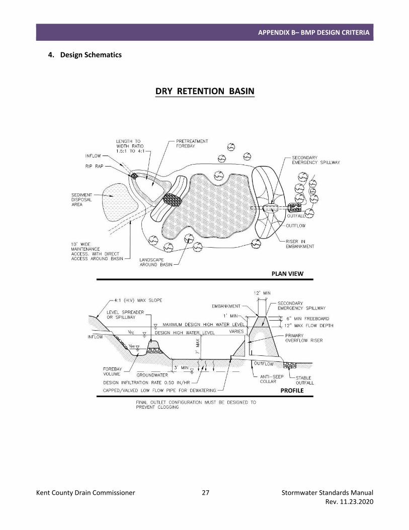
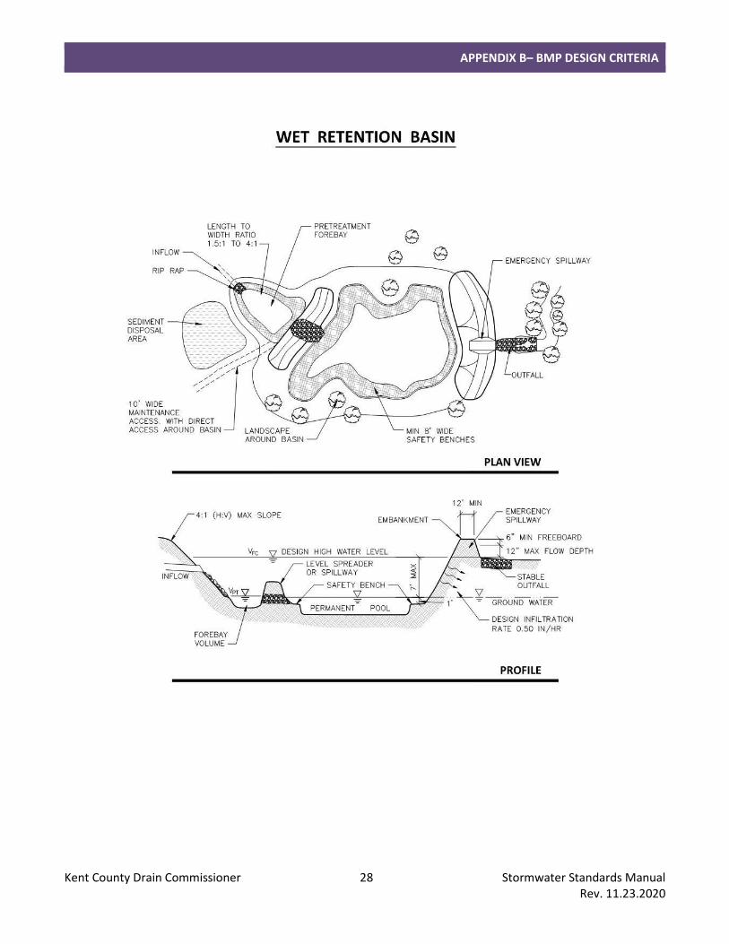
(c.) Freeboard. The top of berm elevation shall be a minimum of 0.5 foot above the design flow depth over the spillway. In no case shall the spillway depth (distance between spillway crest and top of berm) be less than 1 foot.
(d.) Overflow spillways shall be protected with concrete, riprap or a permanent erosion control blanket (preferred) to prevent erosion of the structure. Protection shall extend across the entire spillway up to the top of berm, start on the basin side a minimum of 3 feet below the spillway crest and extend down the spillway to an apron a minimum of 6 feet beyond the toe of the spillway.
e. Access
(1) Berm top width shall be a minimum of 12 feet.
(2) A minimum 10-foot wide maintenance access route from a public or private right-of-way shall be provided to the basin. The access way shall have a vertical grade of no greater than 20% (5:1 H:V slope) and shall be stabilized to withstand the passage of heavy equipment. Direct access to the forebay, control structures and the outlet shall be provided.
f. Supplemental Measures
(1) Supplemental measures may be required to ensure that a retention basin drains sufficiently as the soil becomes less permeable with use. The need for supplemental measures may be based on a number of indicators including:
(a.) Soils with a design infiltration rate between 0.50 and 1.63 inches per hour (Sandy Loam).
(b.) High probability for sedimentation (particularly fines).
(c.) Larger regional basin where there is less control over contributing area runoff.
(d.) Probability of groundwater rising higher than minimum isolation distance.
(2) Supplemental measures may include:
(a.) Leaching basins or infiltration trench placed in the bottom of the basin.
(b.) Valved outlet to drain basin.
(c.) Conversion to a wet basin with sufficient storage volume provided above the permanent pool for reduced infiltration area.
APPENDIX B– BMP DESIGN CRITERIA
Kent County Drain Commissioner 27 Stormwater Standards Manual Rev. 11.23.2020
4. Design Schematics
APPENDIX B– BMP DESIGN CRITERIA
Kent County Drain Commissioner 28 Stormwater Standards Manual Rev. 11.23.2020
APPENDIX B– BMP DESIGN CRITERIA
Kent County Drain Commissioner 29 Stormwater Standards Manual Rev. 11.23.2020
F. Infiltration Practices
1. Summary
Description: Stormwater treatment and storage without a surface outlet.
Application: Practices are typically applicable to small sites and drainage areas.
Types: Dry Well; Leaching Basin; Infiltration Trench; Infiltration Bed; Infiltration Berm.
Pretreatment Required: Yes.
Maintenance Plan: Yes.
Calculation Credits:
Volume Reduction: Count volume stored and infiltrated.
Rate Reduction: Designed for flood control: 100%. Designed for channel protection and/or water quality: Adjust time-of-concentration by dividing storage volume by 10-year peak flow rate.
Water Quality: Count volume stored and infiltrated.
2. Sizing Calculations
a. Infiltration practices may be sized for channel protection or water quality treatment. Use the methods outlined in Part 4 section “Calculating Storage Volumes and Release Rates” to calculate the required volumes. Use the SEMCOG Method to calculate the required storage volume of the BMP.
b. Infiltration practices may be able to provide flood control for small drainage areas. Use the formulas included in Part 4 section “Calculating Storage Volumes and Release Rates, Flood Control, Retention” to calculate the storage volume of the BMP.
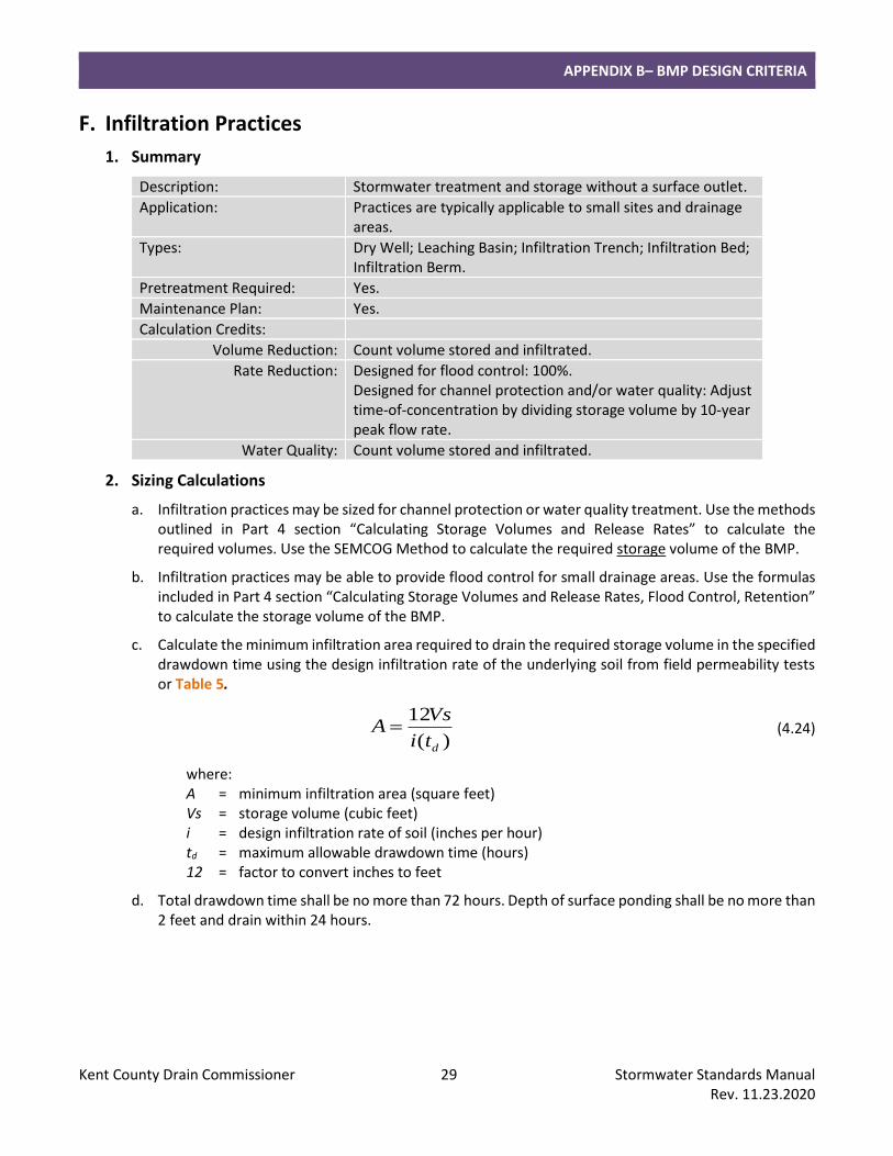
c. Calculate the minimum infiltration area required to drain the required storage volume in the specified drawdown time using the design infiltration rate of the underlying soil from field permeability tests or Table 5.
)(
12
dti
VsA = (4.24)
where: A = minimum infiltration area (square feet) Vs = storage volume (cubic feet) i = design infiltration rate of soil (inches per hour) td = maximum allowable drawdown time (hours) 12 = factor to convert inches to feet
d. Total drawdown time shall be no more than 72 hours. Depth of surface ponding shall be no more than 2 feet and drain within 24 hours.
APPENDIX B– BMP DESIGN CRITERIA
Kent County Drain Commissioner 30 Stormwater Standards Manual Rev. 11.23.2020
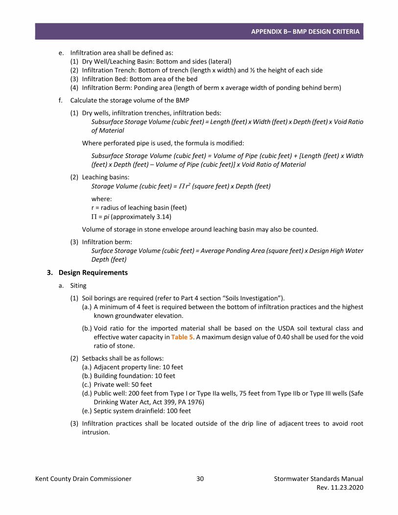
e. Infiltration area shall be defined as: (1) Dry Well/Leaching Basin: Bottom and sides (lateral) (2) Infiltration Trench: Bottom of trench (length x width) and ½ the height of each side (3) Infiltration Bed: Bottom area of the bed (4) Infiltration Berm: Ponding area (length of berm x average width of ponding behind berm)
f. Calculate the storage volume of the BMP
(1) Dry wells, infiltration trenches, infiltration beds: Subsurface Storage Volume (cubic feet) = Length (feet) x Width (feet) x Depth (feet) x Void Ratio of Material
Where perforated pipe is used, the formula is modified:
Subsurface Storage Volume (cubic feet) = Volume of Pipe (cubic feet) + [Length (feet) x Width (feet) x Depth (feet) – Volume of Pipe (cubic feet)] x Void Ratio of Material
(2) Leaching basins:
Storage Volume (cubic feet) = r2 (square feet) x Depth (feet)
where: r = radius of leaching basin (feet)
= pi (approximately 3.14)
Volume of storage in stone envelope around leaching basin may also be counted.
(3) Infiltration berm: Surface Storage Volume (cubic feet) = Average Ponding Area (square feet) x Design High Water Depth (feet)
3. Design Requirements
a. Siting
(1) Soil borings are required (refer to Part 4 section “Soils Investigation”). (a.) A minimum of 4 feet is required between the bottom of infiltration practices and the highest
known groundwater elevation.
(b.) Void ratio for the imported material shall be based on the USDA soil textural class and effective water capacity in Table 5. A maximum design value of 0.40 shall be used for the void ratio of stone.
(2) Setbacks shall be as follows: (a.) Adjacent property line: 10 feet (b.) Building foundation: 10 feet (c.) Private well: 50 feet (d.) Public well: 200 feet from Type I or Type IIa wells, 75 feet from Type IIb or Type III wells (Safe
Drinking Water Act, Act 399, PA 1976) (e.) Septic system drainfield: 100 feet
(3) Infiltration practices shall be located outside of the drip line of adjacent trees to avoid root intrusion.
APPENDIX B– BMP DESIGN CRITERIA
Kent County Drain Commissioner 31 Stormwater Standards Manual Rev. 11.23.2020
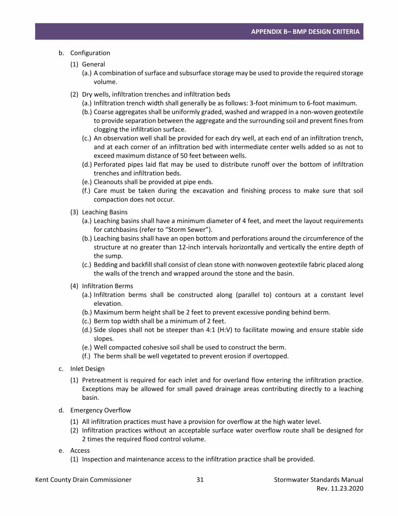
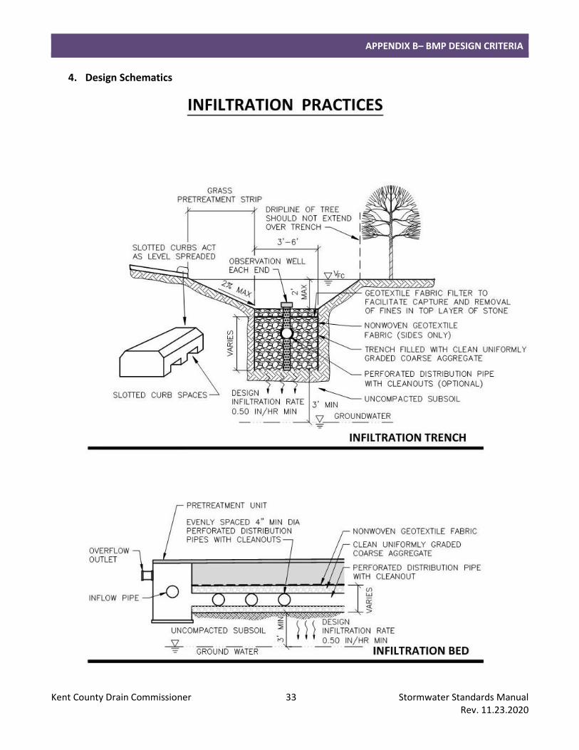
b. Configuration
(1) General (a.) A combination of surface and subsurface storage may be used to provide the required storage
volume.
(2) Dry wells, infiltration trenches and infiltration beds (a.) Infiltration trench width shall generally be as follows: 3-foot minimum to 6-foot maximum. (b.) Coarse aggregates shall be uniformly graded, washed and wrapped in a non-woven geotextile
to provide separation between the aggregate and the surrounding soil and prevent fines from clogging the infiltration surface.
(c.) An observation well shall be provided for each dry well, at each end of an infiltration trench, and at each corner of an infiltration bed with intermediate center wells added so as not to exceed maximum distance of 50 feet between wells.
(d.) Perforated pipes laid flat may be used to distribute runoff over the bottom of infiltration trenches and infiltration beds.
(e.) Cleanouts shall be provided at pipe ends. (f.) Care must be taken during the excavation and finishing process to make sure that soil
compaction does not occur.
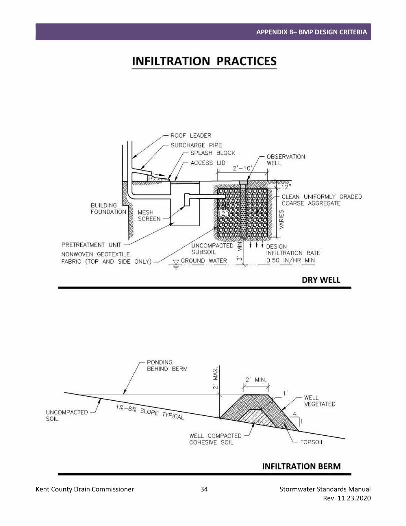
(3) Leaching Basins (a.) Leaching basins shall have a minimum diameter of 4 feet, and meet the layout requirements
for catchbasins (refer to “Storm Sewer”). (b.) Leaching basins shall have an open bottom and perforations around the circumference of the
structure at no greater than 12-inch intervals horizontally and vertically the entire depth of the sump.
(c.) Bedding and backfill shall consist of clean stone with nonwoven geotextile fabric placed along the walls of the trench and wrapped around the stone and the basin.
(4) Infiltration Berms (a.) Infiltration berms shall be constructed along (parallel to) contours at a constant level
elevation. (b.) Maximum berm height shall be 2 feet to prevent excessive ponding behind berm. (c.) Berm top width shall be a minimum of 2 feet. (d.) Side slopes shall not be steeper than 4:1 (H:V) to facilitate mowing and ensure stable side
slopes. (e.) Well compacted cohesive soil shall be used to construct the berm. (f.) The berm shall be well vegetated to prevent erosion if overtopped.
c. Inlet Design
(1) Pretreatment is required for each inlet and for overland flow entering the infiltration practice. Exceptions may be allowed for small paved drainage areas contributing directly to a leaching basin.
d. Emergency Overflow
(1) All infiltration practices must have a provision for overflow at the high water level. (2) Infiltration practices without an acceptable surface water overflow route shall be designed for
2 times the required flood control volume.
e. Access (1) Inspection and maintenance access to the infiltration practice shall be provided.

APPENDIX B– BMP DESIGN CRITERIA
Kent County Drain Commissioner 32 Stormwater Standards Manual Rev. 11.23.2020
(2) The Developer/Owner shall sign a maintenance agreement that requires that the retention basin be monitored for 3-years or until the last home site has been constructed and the lawn is established. The basin shall be inspected every two weeks or within 24 hours after a significant storm event during the growing season or while the soil in the basin is exposed. Any accumulation of sediment on the bottom of the basin shall be clean out and disk the soil in the bottom if necessary. A performance bond shall be submitted to ensure the work will be completed.
APPENDIX B– BMP DESIGN CRITERIA
Kent County Drain Commissioner 33 Stormwater Standards Manual Rev. 11.23.2020
4. Design Schematics
APPENDIX B– BMP DESIGN CRITERIA
Kent County Drain Commissioner 34 Stormwater Standards Manual Rev. 11.23.2020
APPENDIX B– BMP DESIGN CRITERIA
Kent County Drain Commissioner 35 Stormwater Standards Manual Rev. 11.23.2020
G. Bioretention/Rain Garden
1. Summary
Description: Provides stormwater treatment, storage and uptake with or without a surface outlet.
Application: Small sites and drainage areas. Underdrained BMP may be used on small sites to provide extended detention.
Types: Bioretention: Natural-looking herbaceous. Rain garden: Landscaped and manicured. Infiltration; Underdrain at top of storage layer; Underdrain at bottom of storage layer; Lined.
Pretreatment Required: Yes.
Maintenance Plan: Yes.
Calculation Credits:
Volume Reduction: Infiltration: Count volume stored and infiltrated. Underdrained: Count volume stored and infiltrated between bottom of BMP and invert of underdrain.
Rate Reduction: Adjust time-of-concentration by dividing storage volume by 10-year peak flow rate.
Water Quality: Count volume stored and infiltrated, or routed through filter.
2. Sizing Calculations
a. For underdrained BMP, follow criteria for “Constructed Filter.”
b. Bioretention/rain gardens may be sized for channel protection or water quality treatment. Use the methods outlined in Part 4 section “Calculating Storage Volumes and Release Rates” to calculate the required volumes. Use the SEMCOG Method to calculate the required storage volume of the BMP.
c. Bioretention/rain gardens may be able to provide flood control for small drainage areas. Use the formulas included in Part 4 section “Calculating Storage Volumes and Release Rates, Flood Control, Retention” to calculate the storage volume of the BMP.
d. Minimum surface area (loading ratio): 0.06 times contributing impervious area, with a maximum impervious area of 1 acre (43,560 square feet) per bioretention cell.
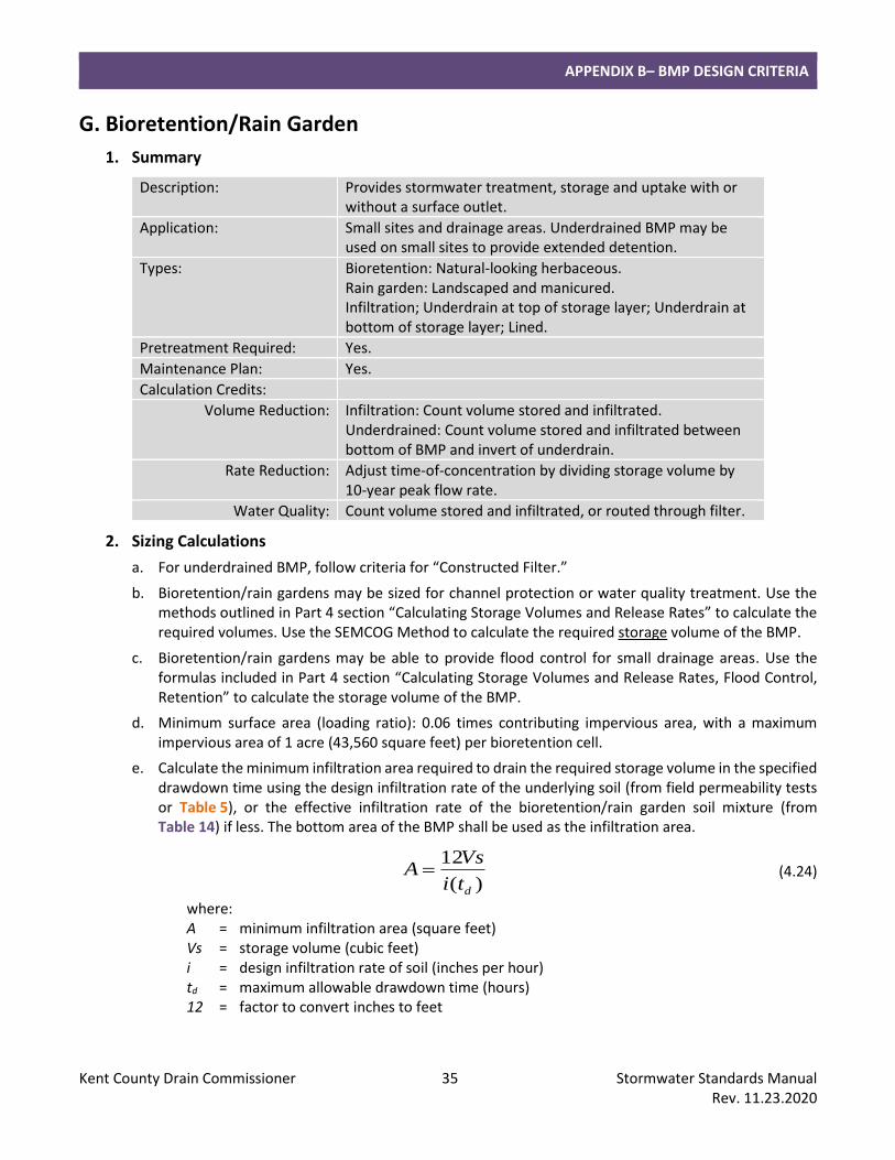
e. Calculate the minimum infiltration area required to drain the required storage volume in the specified drawdown time using the design infiltration rate of the underlying soil (from field permeability tests or Table 5), or the effective infiltration rate of the bioretention/rain garden soil mixture (from Table 14) if less. The bottom area of the BMP shall be used as the infiltration area.
)(
12
dti
VsA = (4.24)
where: A = minimum infiltration area (square feet) Vs = storage volume (cubic feet) i = design infiltration rate of soil (inches per hour) td = maximum allowable drawdown time (hours) 12 = factor to convert inches to feet
APPENDIX B– BMP DESIGN CRITERIA
Kent County Drain Commissioner 36 Stormwater Standards Manual Rev. 11.23.2020
f. Total drawdown time shall be no more than 72 hours. Depth of surface ponding shall be no more than 12 inches and drain within 12 hours. Surface ponding depth may be increased up to 24 inches for bioretention areas and drain within 24 hours.
g. Calculate the storage volume of the BMP:
Average Bed Area (square feet) = [Area at Design High Water Depth (square feet) + Bottom Area (square feet)] / 2
Surface Storage Volume (cubic feet) = Average Bed Area (square feet) x Design High Water Depth (feet)
Subsurface Storage Volume (cubic feet) = Length (feet) x Width (feet) x Depth (feet) x Void Ratio of Material
Total Storage Volume (cubic feet) = Surface Storage Volume (cubic feet) + Subsurface Storage Volume (cubic feet)
3. Design Requirements
a. Siting
(1) Soil borings are required (refer to Part 4 section “Soils Investigation”). (a.) A minimum of 3 feet is required between the bottom of bioretention/rain gardens capable of
infiltration and the highest known groundwater elevation. (b.) A minimum of 2 feet is required between the bottom of lined or underdrained
bioretention/rain gardens and the highest known groundwater elevation. (c.) An underdrain shall be provided for design infiltration rates of the underlying native soil less
than 0.50 inches per hour, or if bioretention/rain garden will be lined. (d.) Void ratio for the amended soil material shall be based on the USDA soil textural class and
effective water capacity in Table 5. A maximum design value of 0.30 shall be used for the void ratio of the amended soil material. A maximum design value of 0.40 shall be used for the void ratio of stone.
(2) Setbacks shall be as follows: (a.) Adjacent property line: 10 feet (b.) Building foundation: 10 feet (c.) Private well: 50 feet (d.) Public well: 200 feet from Type I or Type IIa wells, 75 feet from Type IIb or Type III wells (Safe
Drinking Water Act, Act 399, PA 1976) (e.) Septic system drainfield: 100 feet
b. Configuration
(1) General (a.) The bottom shall be flat to encourage uniform ponding and infiltration. (b.) Minimum bottom width shall be 3 feet. (c.) Bioretention/rain gardens located in areas with steep slopes shall be terraced to minimize
earth disturbance and maximize infiltration area. (d.) Care must be taken during the excavation and finishing process to make sure that soil
compaction does not occur. (e.) Bioretention/rain gardens located in areas of existing soil contamination shall be lined to
prevent infiltration. (f.) Underdrains shall have a 4-inch minimum pipe diameter.
APPENDIX B– BMP DESIGN CRITERIA
Kent County Drain Commissioner 37 Stormwater Standards Manual Rev. 11.23.2020
(g.) All underground pipes shall have clean-outs accessible from the surface. (h.) Pipes shall be sloped to prevent siltation. (i.) Side slopes shall not be steeper than 4:1 (H:V), unless landscape retaining walls are used. (j.) An observation well shall be provided for each bioretention/rain garden without a bottom
underdrain.
(2) Rain gardens (a.) A landscape plan shall be provided.
c. Inlet Design
(1) Inlet pipes shall require energy dissipation. Riprap protection or equivalent erosion control measures shall be used where the velocity exceeds 4 feet per second up to a maximum allowable design velocity of 8 feet per second.
(2) Pretreatment is required for each inlet and for overland flow entering the bioretention/rain garden.
d. Emergency Overflow
(1) All bioretention/rain gardens must have a provision for overflow at the high water level.
e. Materials
(1) Amended soil material shall consist of 18 to 48 inches of the following materials, evenly mixed: Compost: minimum 20%; Sand: 20-80%; Topsoil: maximum 30% (with less than 10% clay content). (a.) Alternative mix designs with ratios outside of the limits provided will be considered with
justification. (b.) The soil mix shall have a pH between 5.5 and 7.5.
(2) Stone shall consist of clean, uniformly graded coarse aggregate.
(3) A woven geotextile fabric shall be placed between the amended soil and the stone, when a stone layer is used.
(4) When used, impermeable liner shall have a maximum permeability of 1 x 10⁻⁷ centimeters per second certified by the manufacturer.
(5) Plant selection shall consider exposure and tolerance to salt, sediment and pollutants, and the design depth of surface storage. Native species are encouraged. (a.) Bioretention: Plugs and seed. (b.) Rain gardens: Container stock.
(6) Mulch shall be applied after planting. (a.) Bioretention: Straw mulch or mulch blanket shall be uniformly applied and tacked. (b.) Rain gardens: Shredded hardwood mulch shall be uniformly applied to a depth of 2 to
3 inches.
f. Access
(1) Inspection and maintenance access to the bioretention/rain garden shall be provided.
APPENDIX B– BMP DESIGN CRITERIA
Kent County Drain Commissioner 38 Stormwater Standards Manual Rev. 11.23.2020
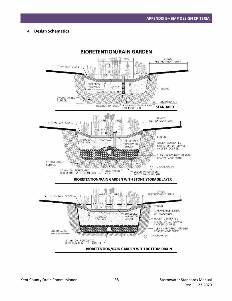
4. Design Schematics
APPENDIX B– BMP DESIGN CRITERIA
Kent County Drain Commissioner 39 Stormwater Standards Manual Rev. 11.23.2020
H. Constructed Filter
1. Summary
Description: Provides stormwater treatment and storage with a surface outlet (underdrain).
Application: Areas with high heavy metal pollutant loads. May be used on small sites to provide extended detention.
Types: Sand; Gravel; Sand/compost mix; Other media. Dry; Static water level within filter media.
Pretreatment Required: Yes.
Maintenance Plan: Yes.
Calculation Credits:
Volume Reduction: None.
Rate Reduction: Adjust time-of-concentration by dividing storage volume by 10-year peak flow rate.
Water Quality: Count volume routed through filter.
2. Sizing Calculations
a. Use the methods outlined in Part 4 section “Calculating Storage Volumes and Release Rates” to calculate the required volumes for channel protection, water quality and/or pretreatment.
b. Calculate filter surface area required to drain the design volume in the specified drawdown time using hydraulic conductivity of filter media:
))((
)(
ffd
f
dhtK
dVA
+= (4.25)
where: A = minimum surface area of filter (square feet) V = design runoff volume (cubic feet) df = depth of filter media (1.5-foot minimum to 3-foot maximum) K = hydraulic conductivity (feet per day) td = maximum allowable drawdown time (days) hf = average head; typically ½ of the maximum head on filter media (feet)
c. Total drawdown time shall be no more than 72 hours. Maximum depth of surface ponding above the filter bed shall be 24 inches and drain within 24 hours.
d. Check whether soil conductivity or hydraulics of underdrain governs.
3. Design Requirements
a. Siting
(1) Soil borings are required (refer to Part 4 section “Soils Investigation”).
(a.) A minimum of 2 foot is required between the bottom of the constructed filter and the highest known groundwater elevation.
(b.) Design values for hydraulic conductivity of the filter media shall be as specified in Table 14. Values for other types of filter media will be reviewed for use on an individual basis.
APPENDIX B– BMP DESIGN CRITERIA
Kent County Drain Commissioner 40 Stormwater Standards Manual Rev. 11.23.2020
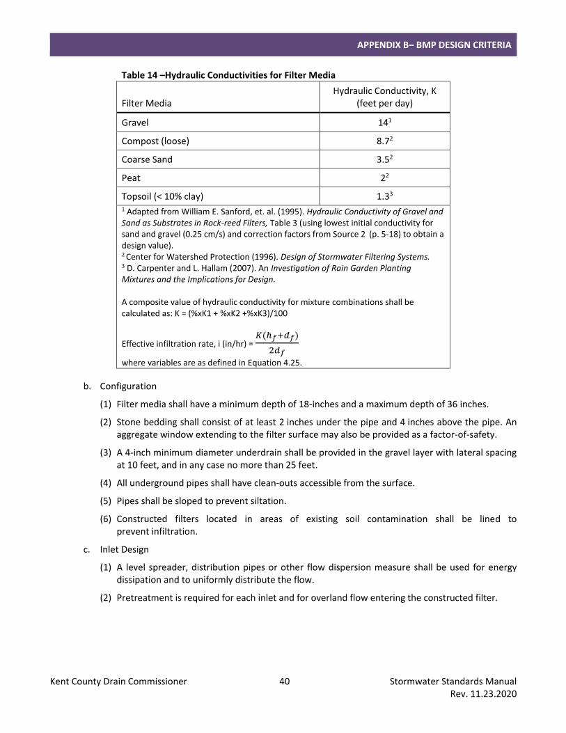
Table 14 –Hydraulic Conductivities for Filter Media
Filter Media Hydraulic Conductivity, K
(feet per day)
Gravel 141
Compost (loose) 8.72
Coarse Sand 3.52
Peat 22
Topsoil (< 10% clay) 1.33
1 Adapted from William E. Sanford, et. al. (1995). Hydraulic Conductivity of Gravel and Sand as Substrates in Rock-reed Filters, Table 3 (using lowest initial conductivity for sand and gravel (0.25 cm/s) and correction factors from Source 2 (p. 5-18) to obtain a design value). 2 Center for Watershed Protection (1996). Design of Stormwater Filtering Systems. 3 D. Carpenter and L. Hallam (2007). An Investigation of Rain Garden Planting Mixtures and the Implications for Design. A composite value of hydraulic conductivity for mixture combinations shall be calculated as: K = (%xK1 + %xK2 +%xK3)/100
Effective infiltration rate, i (in/hr) = 𝐾(ℎ𝑓+𝑑𝑓)
2𝑑𝑓
where variables are as defined in Equation 4.25.
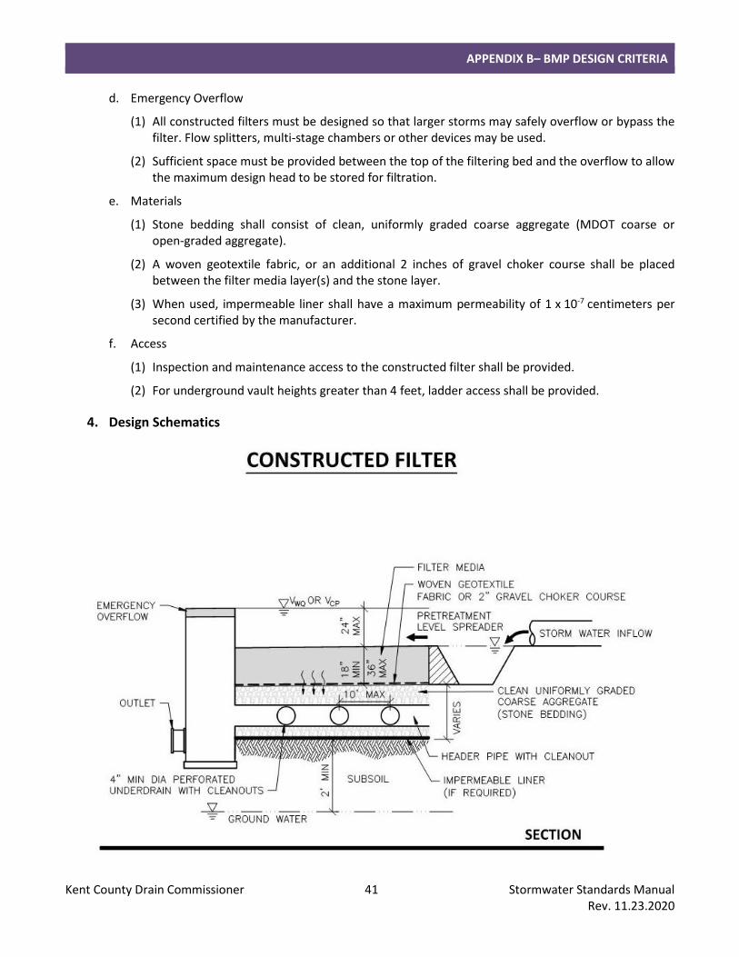
b. Configuration
(1) Filter media shall have a minimum depth of 18-inches and a maximum depth of 36 inches.
(2) Stone bedding shall consist of at least 2 inches under the pipe and 4 inches above the pipe. An aggregate window extending to the filter surface may also be provided as a factor-of-safety.
(3) A 4-inch minimum diameter underdrain shall be provided in the gravel layer with lateral spacing at 10 feet, and in any case no more than 25 feet.
(4) All underground pipes shall have clean-outs accessible from the surface.
(5) Pipes shall be sloped to prevent siltation.
(6) Constructed filters located in areas of existing soil contamination shall be lined to prevent infiltration.
c. Inlet Design
(1) A level spreader, distribution pipes or other flow dispersion measure shall be used for energy dissipation and to uniformly distribute the flow.
(2) Pretreatment is required for each inlet and for overland flow entering the constructed filter.
APPENDIX B– BMP DESIGN CRITERIA
Kent County Drain Commissioner 41 Stormwater Standards Manual Rev. 11.23.2020
d. Emergency Overflow
(1) All constructed filters must be designed so that larger storms may safely overflow or bypass the filter. Flow splitters, multi-stage chambers or other devices may be used.
(2) Sufficient space must be provided between the top of the filtering bed and the overflow to allow the maximum design head to be stored for filtration.
e. Materials
(1) Stone bedding shall consist of clean, uniformly graded coarse aggregate (MDOT coarse or open-graded aggregate).
(2) A woven geotextile fabric, or an additional 2 inches of gravel choker course shall be placed between the filter media layer(s) and the stone layer.
(3) When used, impermeable liner shall have a maximum permeability of 1 x 10⁻⁷ centimeters per second certified by the manufacturer.
f. Access
(1) Inspection and maintenance access to the constructed filter shall be provided.
(2) For underground vault heights greater than 4 feet, ladder access shall be provided.
4. Design Schematics
APPENDIX B– BMP DESIGN CRITERIA
Kent County Drain Commissioner 42 Stormwater Standards Manual Rev. 11.23.2020
I. Planter Box 1. Summary
Description: A type of rain garden. Application: Small sites or highly urban areas. Underdrained BMP may be
used on small sites to provide extended detention. Types: Infiltration; Underdrain at top of storage layer; Underdrain at
bottom of storage layer; Lined. Pretreatment Required: No. Maintenance Plan: Yes. Calculation Credits:
Volume Reduction: Infiltration: Count volume stored and infiltrated. Underdrained: Count volume stored and infiltrated between bottom of BMP and invert of underdrain.
Rate Reduction: Adjust time-of-concentration by dividing storage volume by 10-year peak flow rate.
Water Quality: Count volume stored and infiltrated, or routed through filter.
2. Sizing Calculations
a. For underdrained BMP, follow criteria for “Constructed Filter.”
b. Planter boxes may be sized for channel protection or water quality treatment. Use the methods outlined in Part 4 section “Calculating Storage Volumes and Release Rates” to calculate the required volumes. Use the SEMCOG Method to calculate the required storage volume of the BMP.
c. Minimum surface area (loading ratio): 0.06 times contributing impervious area, with a maximum impervious area of 15,000 square feet per planter box.
d. Calculate the minimum infiltration area required to drain the required storage volume in the specified drawdown time using the design infiltration rate of the underlying soil (from field permeability testing or Table 5), or the effective infiltration rate of the planter box soil mixture (from Table 14) if less.
)(
12
dti
VsA = (4.24)
where: A = minimum infiltration area (square feet) Vs = storage volume (cubic feet) i = design infiltration rate of soil (inches per hour) td = maximum allowable drawdown time (hours) 12 factor to convert inches to feet
e. Total drawdown time shall be no more than 12 hours. Depth of surface ponding shall be no more than 12 inches and drain within 4 hours.
f. The bottom area of the BMP shall be used as the infiltration area.
APPENDIX B– BMP DESIGN CRITERIA
Kent County Drain Commissioner 43 Stormwater Standards Manual Rev. 11.23.2020
g. Calculate the storage volume of the BMP:
Surface Storage Volume (cubic feet) = Bed Area (square feet) x Design High Water Depth (feet)
Subsurface Storage Volume (cubic feet) = Length (feet) x Width (feet) x Depth (feet) x Void Ratio of Material
Total Storage Volume (cubic feet) = Surface Storage Volume (cubic feet) + Subsurface Storage Volume (cubic feet)
3. Design Requirements
a. Siting
(1) Soil borings are required (refer to Part 4 section “Soils Investigation”).
(a.) A minimum of 3 feet is required between the bottom of the planter box and the highest known groundwater elevation.
(b.) A minimum of 2 foot is required between the bottom of a lined or underdrained planter box and the highest known groundwater elevation.
(c.) An underdrain shall be provided for design infiltration rates less than 0.50 inches per hour, or if planter box will be lined.
(d.) Void ratio for the amended soil material shall be based on the USDA soil textural class and effective water capacity in Table 5. A maximum design value of 0.30 shall be used for the void ratio of the amended soil material. A maximum design value of 0.40 shall be used for the void ratio of stone.
b. Configuration
(1) A combination of surface and subsurface storage may be used to provide the required storage volume.
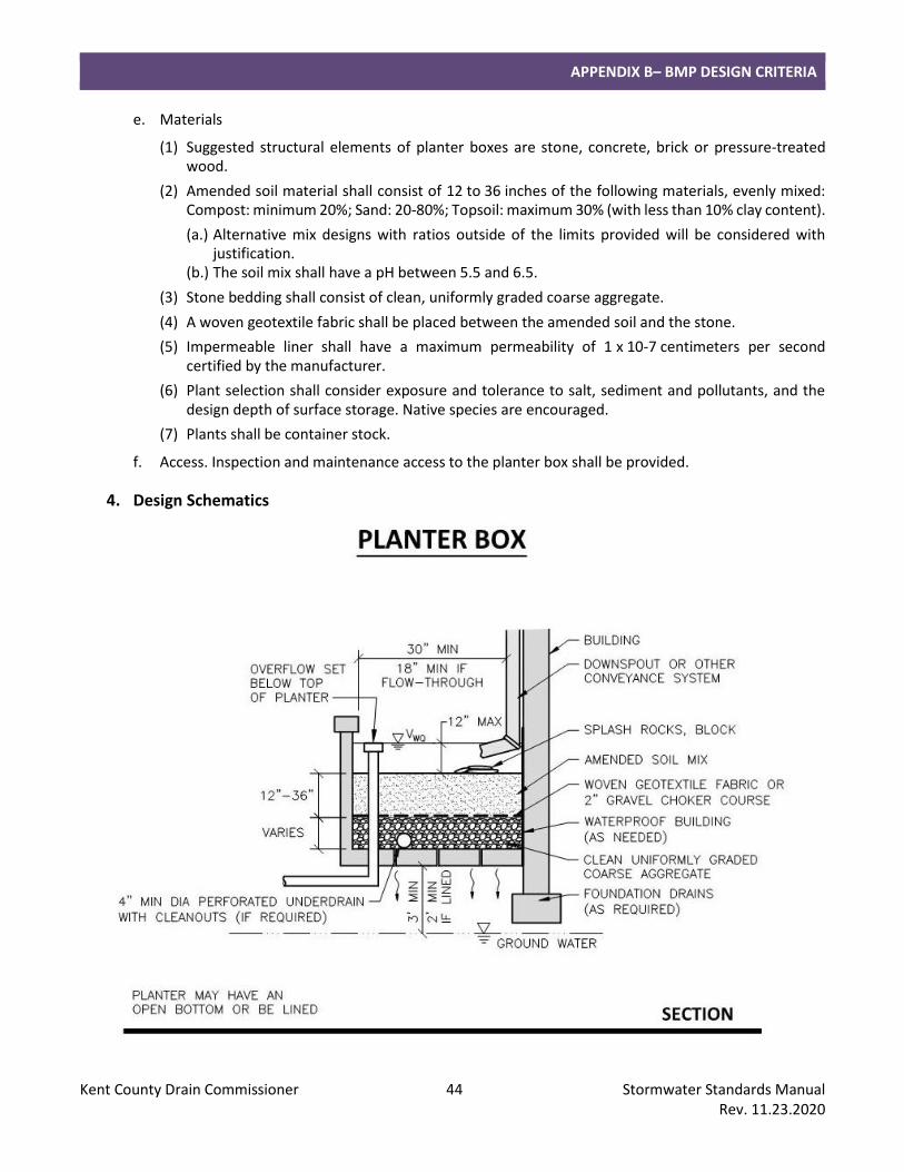
(2) Minimum width of planter boxes shall be 30 inches, or 18 inches if flow-through.
(3) Care must be taken during the excavation and finishing process to make sure that soil compaction does not occur.
(4) Planter boxes located in areas of existing soil contamination shall be lined to prevent infiltration.
(5) Underdrains shall have a 4-inch minimum pipe diameter.
(6) All underground pipes shall have clean-outs accessible from the surface.
(7) Pipes shall be sloped to prevent siltation.
(8) A planting plan shall be provided.
c. Inlet Design
(1) Inlet pipes shall require energy dissipation. Riprap protection or equivalent erosion control measures shall be used where the velocity exceeds 4 feet per second, up to a maximum allowable design velocity of 8 feet per second.
d. Emergency Overflow
(1) All planter boxes must have a provision for overflow at the high water level.
APPENDIX B– BMP DESIGN CRITERIA
Kent County Drain Commissioner 44 Stormwater Standards Manual Rev. 11.23.2020
e. Materials
(1) Suggested structural elements of planter boxes are stone, concrete, brick or pressure-treated wood.
(2) Amended soil material shall consist of 12 to 36 inches of the following materials, evenly mixed: Compost: minimum 20%; Sand: 20-80%; Topsoil: maximum 30% (with less than 10% clay content).
(a.) Alternative mix designs with ratios outside of the limits provided will be considered with justification.
(b.) The soil mix shall have a pH between 5.5 and 6.5.
(3) Stone bedding shall consist of clean, uniformly graded coarse aggregate.
(4) A woven geotextile fabric shall be placed between the amended soil and the stone.
(5) Impermeable liner shall have a maximum permeability of 1 x 10⁻⁷ centimeters per second certified by the manufacturer.
(6) Plant selection shall consider exposure and tolerance to salt, sediment and pollutants, and the design depth of surface storage. Native species are encouraged.
(7) Plants shall be container stock.
f. Access. Inspection and maintenance access to the planter box shall be provided.
4. Design Schematics
APPENDIX B– BMP DESIGN CRITERIA
Kent County Drain Commissioner 45 Stormwater Standards Manual Rev. 11.23.2020
J. Pervious Pavement
1. Summary
Description: Provides stormwater treatment and storage with or without a surface outlet.
Application: Parking lots, alleys and roads and drives with low-volume vehicular traffic and minimal turning motions.
Types: Infiltration; Underdrain at top of storage layer; Underdrain at bottom of storage layer; Lined.
Pretreatment Required: No.
Maintenance Plan: Yes.
Calculation Credits:
Volume Reduction: Infiltration: Count volume stored and infiltrated (limited by design rainfall on pavement and roof). Underdrained: Count volume stored and volume infiltrated between bottom of BMP and invert of underdrain (limited by design rainfall on pavement and roof).
Rate Reduction: Infiltration: 100%. Underdrained: Calculated allowable release rate.
Water Quality: Count volume stored and infiltrated, or volume filtered.
2. Sizing Calculations
a. Use the methods outlined in Part 4 section “Calculating Storage Volumes and Release Rates” to calculate the required volumes for water quality and channel protection.
b. The required storage volume shall be equal to the runoff volume from the contributing surface area (pavement, roof) for the design flood control event.
c. The bottom area of the BMP shall be used as the infiltration area.
d. Maximum allowable drawdown time shall be 72 hours.
e. Calculate the subsurface storage volume of the BMP:
Subsurface Storage Volume (cubic feet) = Length (feet) x Width (feet) x Depth (feet) x Void Ratio of Material
f. For underdrained BMP, follow criteria for “Constructed Filter.”
3. Design Requirements
a. Siting
(1) Soil borings are required (refer to Part 4 section “Soils Investigation”).
(a.) A minimum of 3 feet is required between the bottom of pervious pavement capable of infiltration and the highest known groundwater elevation.
(b.) A minimum of 2 foot is required between the bottom of lined or underdrained pervious pavement and the highest known groundwater elevation.
(c.) An underdrain shall be provided for design infiltration rates less than 0.50 inches per hour, or if stone bed will be lined.
(d.) A maximum design value of 0.40 shall be used for the void ratio of stone.
APPENDIX B– BMP DESIGN CRITERIA
Kent County Drain Commissioner 46 Stormwater Standards Manual Rev. 11.23.2020
(2) Runoff from offsite areas shall not be directed onto pervious pavement surface.
b. Configuration
(1) The stone bed shall be flat to encourage uniform ponding and infiltration.
(2) For pervious pavements located in areas with steep slopes, stone beds shall be terraced to maximize infiltration area.
(3) Pervious pavements located in areas of existing soil contamination shall be lined to prevent infiltration.
(4) Underdrains shall have a 4-inch minimum pipe diameter with lateral spacing at 10 feet, and in any case no more than 25 feet.
(5) All underground pipes shall have clean-outs accessible from the surface.
(6) Pipes shall be sloped to prevent siltation.
c. Inlet Design
(1) Pervious pavements shall have a backup method for water to enter the storage bed. Backup drainage may consist of an unpaved 1- to 2-foot wide stone edge or inlets with sediment traps.
d. Emergency Overflow
(1) Stone beds must have a provision for overflow below the level of the pavement surface when an underdrain is not already provided.
e. Materials
(1) Stone bed shall consist of 8 to 36 inches of clean, uniformly graded coarse aggregate.
(2) A woven geotextile fabric or 2-inch gravel choker course shall be placed between the pervious pavement and stone bed.
(3) A nonwoven geotextile fabric or liner shall be placed between the stone bed and the subsoil for underdrained pavements.
(4) Impermeable liner shall have a maximum permeability of 1 x 10⁻⁷ centimeters per second certified by the manufacturer.
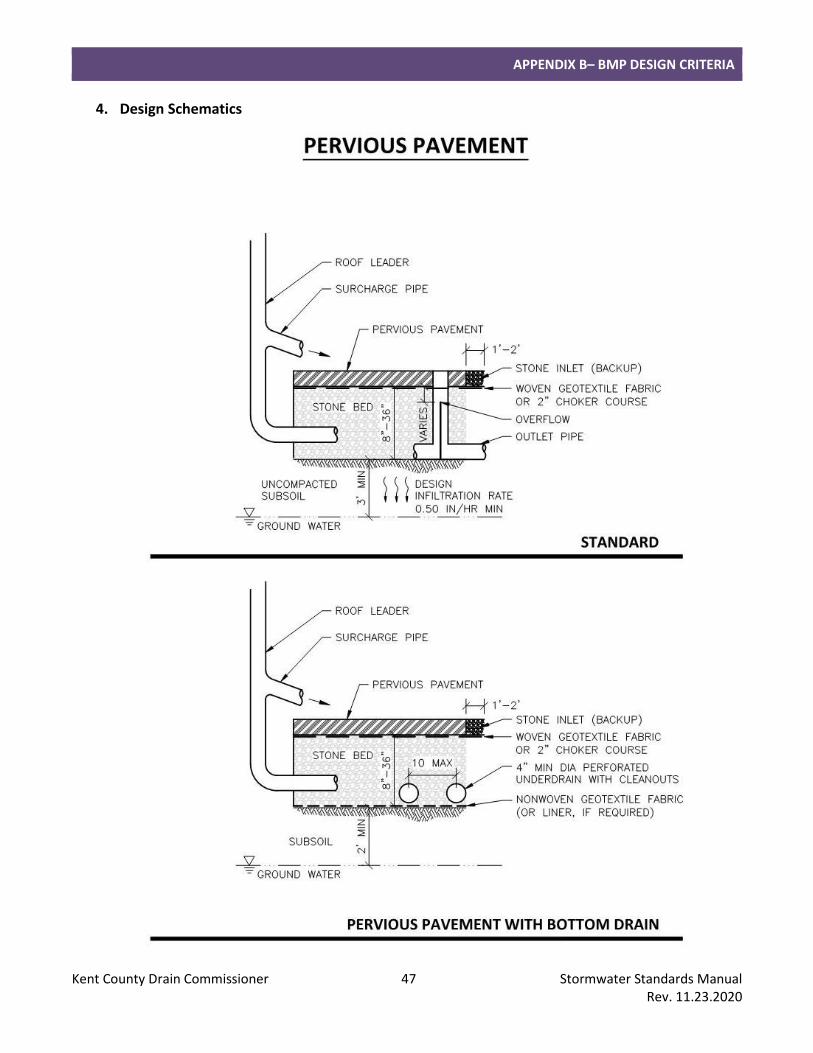
APPENDIX B– BMP DESIGN CRITERIA
Kent County Drain Commissioner 47 Stormwater Standards Manual Rev. 11.23.2020
4. Design Schematics
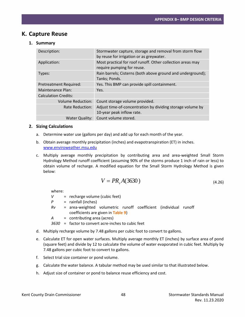
APPENDIX B– BMP DESIGN CRITERIA
Kent County Drain Commissioner 48 Stormwater Standards Manual Rev. 11.23.2020
K. Capture Reuse
1. Summary
Description: Stormwater capture, storage and removal from storm flow by reuse for irrigation or as greywater.
Application: Most practical for roof runoff. Other collection areas may require pumping for reuse.
Types: Rain barrels; Cisterns (both above ground and underground); Tanks; Ponds.
Pretreatment Required: Yes. This BMP can provide spill containment.
Maintenance Plan: Yes.
Calculation Credits:
Volume Reduction: Count storage volume provided.
Rate Reduction: Adjust time-of-concentration by dividing storage volume by 10-year peak inflow rate.
Water Quality: Count volume stored.
2. Sizing Calculations
a. Determine water use (gallons per day) and add up for each month of the year.
b. Obtain average monthly precipitation (inches) and evapotranspiration (ET) in inches. www.enviroweather.msu.edu
c. Multiply average monthly precipitation by contributing area and area-weighted Small Storm Hydrology Method runoff coefficient (assuming 90% of the storms produce 1 inch of rain or less) to obtain volume of recharge. A modified equation for the Small Storm Hydrology Method is given below:
)3630(APRV v= (4.26)
where: V = recharge volume (cubic feet) P = rainfall (inches) Rv = area-weighted volumetric runoff coefficient (individual runoff
coefficients are given in Table 9) A = contributing area (acres) 3630 = factor to convert acre-inches to cubic feet
d. Multiply recharge volume by 7.48 gallons per cubic foot to convert to gallons.
e. Calculate ET for open water surfaces. Multiply average monthly ET (inches) by surface area of pond (square feet) and divide by 12 to calculate the volume of water evaporated in cubic feet. Multiply by 7.48 gallons per cubic foot to convert to gallons.
f. Select trial size container or pond volume.
g. Calculate the water balance. A tabular method may be used similar to that illustrated below.
h. Adjust size of container or pond to balance reuse efficiency and cost.
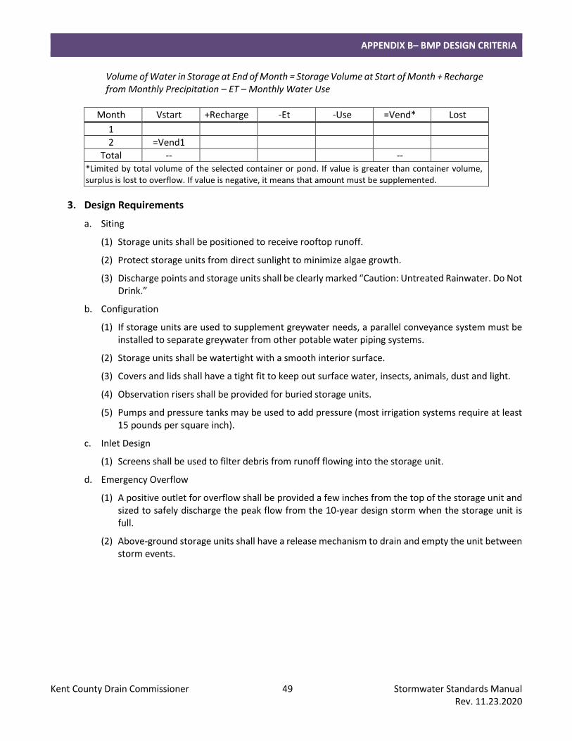
APPENDIX B– BMP DESIGN CRITERIA
Kent County Drain Commissioner 49 Stormwater Standards Manual Rev. 11.23.2020
Volume of Water in Storage at End of Month = Storage Volume at Start of Month + Recharge from Monthly Precipitation – ET – Monthly Water Use
Month Vstart +Recharge -Et -Use =Vend* Lost
1
2 =Vend1
Total -- -- *Limited by total volume of the selected container or pond. If value is greater than container volume, surplus is lost to overflow. If value is negative, it means that amount must be supplemented.
3. Design Requirements
a. Siting
(1) Storage units shall be positioned to receive rooftop runoff.
(2) Protect storage units from direct sunlight to minimize algae growth.
(3) Discharge points and storage units shall be clearly marked “Caution: Untreated Rainwater. Do Not Drink.”
b. Configuration
(1) If storage units are used to supplement greywater needs, a parallel conveyance system must be installed to separate greywater from other potable water piping systems.
(2) Storage units shall be watertight with a smooth interior surface.
(3) Covers and lids shall have a tight fit to keep out surface water, insects, animals, dust and light.
(4) Observation risers shall be provided for buried storage units.
(5) Pumps and pressure tanks may be used to add pressure (most irrigation systems require at least 15 pounds per square inch).
c. Inlet Design
(1) Screens shall be used to filter debris from runoff flowing into the storage unit.
d. Emergency Overflow
(1) A positive outlet for overflow shall be provided a few inches from the top of the storage unit and sized to safely discharge the peak flow from the 10-year design storm when the storage unit is full.
(2) Above-ground storage units shall have a release mechanism to drain and empty the unit between storm events.
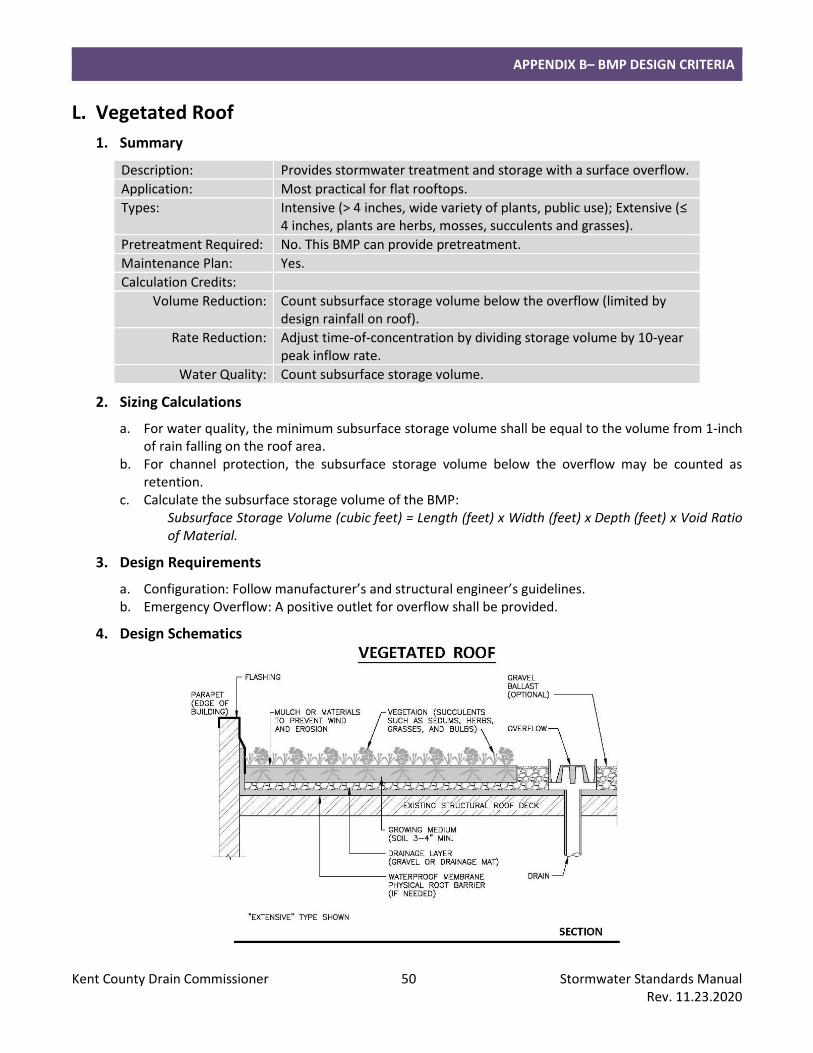
APPENDIX B– BMP DESIGN CRITERIA
Kent County Drain Commissioner 50 Stormwater Standards Manual Rev. 11.23.2020
L. Vegetated Roof
1. Summary
Description: Provides stormwater treatment and storage with a surface overflow.
Application: Most practical for flat rooftops.
Types: Intensive (> 4 inches, wide variety of plants, public use); Extensive (≤ 4 inches, plants are herbs, mosses, succulents and grasses).
Pretreatment Required: No. This BMP can provide pretreatment.
Maintenance Plan: Yes.
Calculation Credits:
Volume Reduction: Count subsurface storage volume below the overflow (limited by design rainfall on roof).
Rate Reduction: Adjust time-of-concentration by dividing storage volume by 10-year peak inflow rate.
Water Quality: Count subsurface storage volume.
2. Sizing Calculations
a. For water quality, the minimum subsurface storage volume shall be equal to the volume from 1-inch of rain falling on the roof area.
b. For channel protection, the subsurface storage volume below the overflow may be counted as retention.
c. Calculate the subsurface storage volume of the BMP: Subsurface Storage Volume (cubic feet) = Length (feet) x Width (feet) x Depth (feet) x Void Ratio of Material.
3. Design Requirements
a. Configuration: Follow manufacturer’s and structural engineer’s guidelines. b. Emergency Overflow: A positive outlet for overflow shall be provided.
4. Design Schematics
APPENDIX B– BMP DESIGN CRITERIA
Kent County Drain Commissioner 51 Stormwater Standards Manual Rev. 11.23.2020
M. Water Quality Device
1. Summary
Description: Stormwater treatment unit.
Application: Practical for small sites and drainage areas.
Types: Oil and grit separator; Hydrodynamic separator.
Pretreatment Required: No. This BMP can provide pretreatment and spill containment
Maintenance Plan: Yes.
Calculation Credits:
Volume Reduction: None.
Rate Reduction: None.
Water Quality: Count volume routed through BMP.
2. Sizing Calculations
a. Select water quality device unit/model based on manufacturer’s recommendations.
b. When the device is used to provide spill containment, the minimum spill containment volume shall be provided between the normal water level and the entrance of the outlet pipe to capture a slug pollutant load from an accidental spill of toxic materials.
3. Design Requirements
a. Configuration
(1) The geometry of the water quality device shall promote the trapping of floatables and sediments.
(2) The water quality device shall be designed to prevent surcharging in pipes upstream of the device.
b. Emergency Overflow
(1) A bypass overflow shall be designed to convey the 10-year peak discharge at a minimum without release of trapped sediments and pollutants.
(2) The outlet from the overflow shall not be submerged under normal conditions.
APPENDIX B– BMP DESIGN CRITERIA
Kent County Drain Commissioner 52 Stormwater Standards Manual Rev. 11.23.2020
N. Sediment Forebay
1. Summary
Description: Stormwater pretreatment practice.
Application: Typically used with a detention or retention basin.
Types: Wet basin; Dry basin; Level spreader.
Pretreatment Required: No. This BMP can provide pretreatment.
Maintenance Plan: Yes.
Calculation Credits:
Volume Reduction: None.
Rate Reduction: None.
Water Quality: Count volume routed through BMP.
2. Sizing Calculations
a. Size for pretreatment (refer to Part 4 section “Calculating Storage Volumes and Release Rates, Pretreatment”).
b. The pretreatment volume is the volume of the forebay to the elevation of the level spreader or overflow spillway including any permanent pool.
3. Design Requirements
a. Siting
(1) Where more than one inlet pipe is required, the calculated forebay volume shall be pro-rated by flow contribution of each inlet.
b. Configuration
(1) The sediment forebay shall be a separate sump, which can be formed by grading.
(2) The minimum surface area shall be 25% of the pretreatment volume.
(3) The length-to-width ratio shall be a minimum of 1.5:1 and a maximum of 4:1 to allow for adequate hydraulic length yet minimize scour velocities.
(4) The top-of-berm elevation between the forebay and the basin shall be a minimum of 1 foot below the outer berm elevation.
(5) The overflow spillway shall be sized using Equation 4.23 and designed to prevent erosion.
4. Design Schematics
a. See “Detention Basin” and “Retention Basin” BMPs.
APPENDIX B– BMP DESIGN CRITERIA
Kent County Drain Commissioner 53 Stormwater Standards Manual Rev. 11.23.2020
O. Spill Containment Cell
1. Summary
Description: Lined stormwater pretreatment practice.
Application: Typically used with a detention or retention basin.
Types: Wet cell; Extended detention cell.
Pretreatment Required: No. This BMP can provide pretreatment and spill containment.
Maintenance Plan: Yes.
Calculation Credits:
Volume Reduction: None.
Rate Reduction: None.
Water Quality: Count volume routed through BMP.
2. Sizing Calculations
a. Size for pretreatment (refer to Part 4 section “Calculating Storage Volumes and Release Rates, Pretreatment”).
b. The pretreatment volume is the volume of the spill containment cell to the elevation of the level spreader or overflow spillway including any permanent pool.
c. The spill containment volume is the storage volume between the normal water level and the entrance of the outlet pipe. The minimum spill containment volume shall be provided to capture a slug pollutant load from an accidental spill of toxic materials.
3. Design Requirements
a. Siting
(1) All inlets shall enter the spill containment cell unless the inlet collects stormwater exclusively from non-hotspot areas (i.e. office parking, courtyard, roof.)
b. Configuration
(1) General
(a.) The minimum surface area shall be 25% of the pretreatment volume.
(b.) The length-to-width ratio shall be a minimum of 1.5:1, and a maximum of 4:1 to allow for adequate hydraulic length yet minimize scour velocities.
(c.) The top-of-berm elevation between the spill containment cell and the basin shall be a minimum of 1 foot below the outer berm elevation.
(d.) Side slopes shall not be steeper than 4:1 (H:V).
(e.) Minimum depth of the permanent pool shall be 3 feet.
(f.) The permanent pool shall have two safety benches, each a minimum of 2 feet in width at a maximum slope of 10%. The first bench shall be located 1 foot above the permanent pool level; the second bench shall be located 1 foot below the permanent pool level.
APPENDIX B– BMP DESIGN CRITERIA
Kent County Drain Commissioner 54 Stormwater Standards Manual Rev. 11.23.2020
c. Outlet Design
(1) The outlet structure from the spill containment cell shall be designed to draw water from the central portion of the water column within the cell to trap floatables and contain sediments. The inlet of the transfer pipe shall be located a minimum of 1 foot below the normal water level, and a minimum of 1 foot above the bottom of the spill containment cell or manhole sump.
(2) The transfer pipe(s) between the spill containment cell and the basin shall be sized for the peak inflow from a 10-year rainfall event.
(3) Minimum pipe diameter shall be 12 inches.
d. Emergency Overflow
(1) The crest of the level spreader or overflow spillway from the spill containment cell shall be set 0.1 feet above the calculated 10-year hydraulic head.
(2) The overflow spillway from the spill containment cell shall be sized using Equation 4.23 and designed to prevent erosion.
e. Materials
(1) The spill containment cell shall be lined with impermeable materials extending up to the design high water elevation. A minimum 18-inch-thick clay layer, or an impermeable liner protected with a minimum 12 inches of soil cover are acceptable alternatives. Maximum allowable permeability shall be 1 x 10⁻⁷ centimeters per second as determined by the geotechnical consultant for clay placement, or manufacturer’s certificate for liner products.
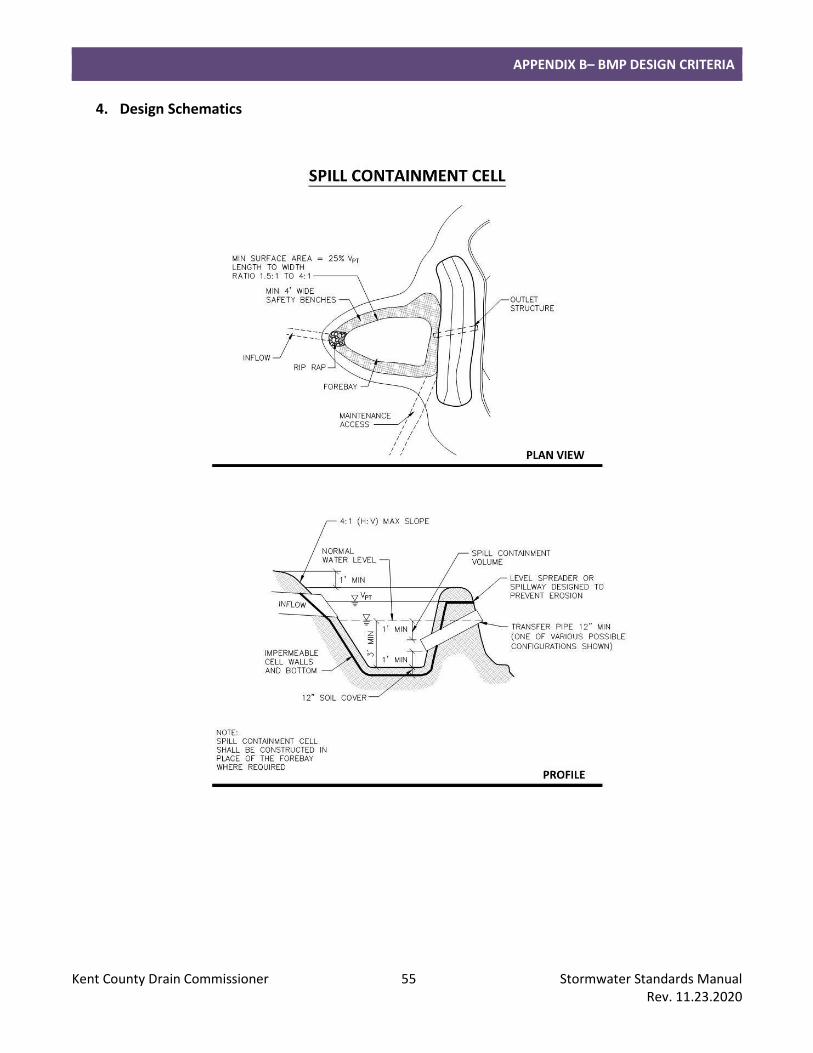
APPENDIX B– BMP DESIGN CRITERIA
Kent County Drain Commissioner 55 Stormwater Standards Manual Rev. 11.23.2020
4. Design Schematics
APPENDIX B– BMP DESIGN CRITERIA
Kent County Drain Commissioner 56 Stormwater Standards Manual Rev. 11.23.2020
P. Bioswale and Water Quality Swale
1. Summary
Description: Bioswale: Vegetated swale designed to capture and treat stormwater within a dry storage layer beneath the base of the channel. Water Quality Swale: Lined swale designed to provide spill containment.
Application: Bioswale: Linear projects or areas. Water Quality Swale: Small sites in lieu of a spill containment cell when a permanent pool is not desirable.
Types: Dry swale; Swale with check dams.
Pretreatment Required: No. This BMP can provide pretreatment and spill containment.
Maintenance Plan: Yes.
Calculation Credits:
Volume Reduction: Bioswale: Count volume stored and infiltrated.
Rate Reduction: Adjust time-of-concentration by dividing storage volume by 10-year peak flow rate.
Water Quality: Bioswale: Count volume stored and infiltrated, or routed through filter. Water Quality Swale: Count volume routed through filter.
2. Sizing Calculations
a. Size for pretreatment (refer to Part 4 section “Calculating Storage Volumes and Release Rates, Pretreatment”).
b. The pretreatment volume is the volume of the voids within the filter media including any temporary surface storage volume to the elevation of the overflow, and including any permanent pool within the outlet structure.
c. The spill containment volume is the storage volume between the normal water level in the filter and the entrance of the outlet pipe. The minimum spill containment volume shall be provided to capture a slug pollutant load from an accidental spill of toxic materials.
d. Depth of surface ponding shall be no more than 2 feet and drain within 24 hours. Use Equation 4.25 and Table 14 from “Constructed Filter” to calculate drain time.
e. The swale shall be designed to pass the 10-year peak discharge with a minimum of 6-inches of freeboard to the top of bank.
f. Volume Behind Check Dam (if used with bioswale)
(1) Calculate the wedge shaped storage volume behind each check dam:
Storage Volume (cubic feet) = 0.5 x Length of Swale Impoundment Area per Check Dam (feet) x Depth of Check Dam (feet) x [Top Width of Check Dam (feet) + Bottom Width of Check Dam (feet)] / 2
3. Design Requirements
a. Siting
APPENDIX B– BMP DESIGN CRITERIA
Kent County Drain Commissioner 57 Stormwater Standards Manual Rev. 11.23.2020
(1) All inlets shall enter the water quality swale unless the inlet collects stormwater exclusively from non-hotspot areas (i.e. office parking, courtyard, roof).
b. Configuration
(1) The bottom of the water quality swale shall be flat to encourage uniform ponding and filtration. Bioswales shall have a maximum longitudinal slope of 1%.
(2) The swale shall have a minimum bottom width of 2 feet and a maximum bottom width of 10 feet.
(3) Side slopes shall be 4:1 (H:V) or flatter.
(4) Sand filter shall have a minimum depth of 18 inches and a maximum depth of 36 inches.
(5) Stone bedding shall consist of at least 2 inches under the pipe and 4 inches above the pipe. An aggregate window extending to the filter surface may also be provided as a factor-of-safety.
(6) Underdrains shall have a 4-inch minimum pipe diameter.
(7) All underground pipes shall have clean-outs accessible from the surface.
(8) Pipes shall be sloped to prevent siltation.
c. Check Dam Design
(1) Check dams may be used along bioswales to encourage ponding and infiltration.
(2) Check dams shall be earthen or other impervious design. Rock check dams are not suitable for infiltration.
(3) Maximum ponding depth behind check dams shall be 24 inches.
(4) Minimum top width of earthen check dam shall be 2 feet.
(5) Check dams shall be keyed into the bottom and sides of the swale a minimum of 1-foot on all sides. The height of the key must exceed the 10-year water surface elevation by a minimum of 6 inches on both sides.
(6) The center of the check dam crest must be below the sides of the check dam by a minimum of 12 inches.
(7) The crest of a downstream check dam shall be no lower than the downstream toe of the upstream check dam.
(8) Erosion control measures (i.e. riprap, turf reinforcement mat) shall be used to protect the integrity of the check dam and downstream toe.
d. Inlet Design
(1) Inlet pipes shall require energy dissipation. Riprap protection or equivalent erosion control measures shall be used where the velocity exceeds 4 feet per second up to a maximum allowable design velocity of 8 feet per second.
e. Outlet Design
(1) The containment structure shall be constructed within a manhole and be designed to draw water from the central portion of the water column within the manhole to trap floatables and contain sediments in a minimum 3-foot sump.
(2) The swale shall be designed to pass the 10-year peak discharge.
f. Overflow
APPENDIX B– BMP DESIGN CRITERIA
Kent County Drain Commissioner 58 Stormwater Standards Manual Rev. 11.23.2020
(1) A positive outlet for overflow shall be provided.
(2) A catch basin and outlet pipe may be used to convey the 10-year peak discharge. In a water quality swale, this must be a separate structure, or chamber within the containment manhole to prevent the captured low-density fluids from becoming entrained in the water when surface inflow enters the structure.
g. Materials
(1) Top Dressing
(a.) Native or imported permeable soil (sand and gravel); or where turf establishment is desired
(b.) 3-inches of compost tilled into the top 6-inches of native permeable soil (equivalent to a 9-inch homogenous mixture of 70% sand; 30% compost); or
(c.) 4-inches of topsoil tilled into the top 6-inches of native permeable soil (equivalent to a 10-inch homogenous mixture with maximum 20% silts, 4% clay, and 80% to 92% sand).
(d.) The soil mix shall have a pH between 5.5 and 7.5.
(e.) Topsoil shall be sandy loam, loamy sand or loam per USDA Soil Textural Triangle with 20% to 50% fines by volume (silt and clay with <10% clay), and 2% to 8% organic matter by dry weight.
(2) Stone bedding shall consist of clean, uniformly graded coarse aggregate.
(3) A woven geotextile fabric or 2-inch gravel choker course shall be placed between the sand and the stone bedding.
(4) The water quality swale shall be lined with impermeable materials extending up to the design high water elevation. A minimum 18-inch-thick clay layer, or an impermeable liner protected with a minimum 12-inches of soil cover are acceptable alternatives. Maximum allowable permeability shall be 1 x 10⁻⁷ centimeters per second as determined by the geotechnical consultant for clay placement, or manufacturer’s certificate for liner products.
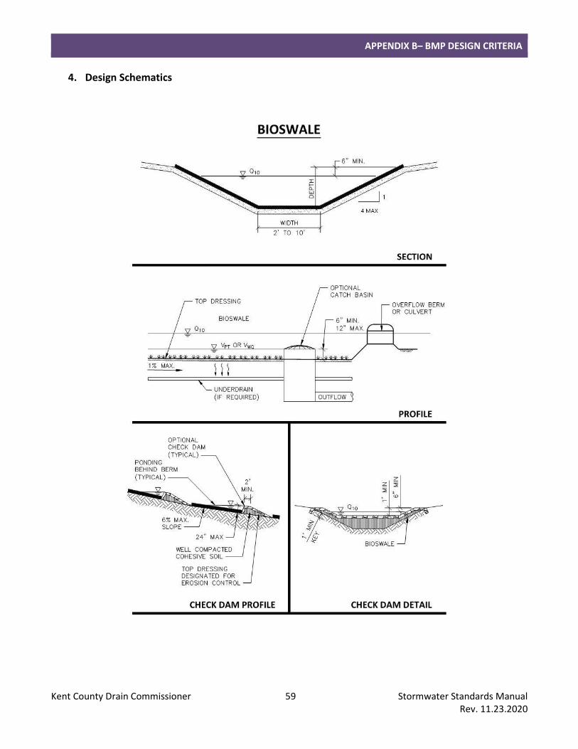
APPENDIX B– BMP DESIGN CRITERIA
Kent County Drain Commissioner 59 Stormwater Standards Manual Rev. 11.23.2020
4. Design Schematics
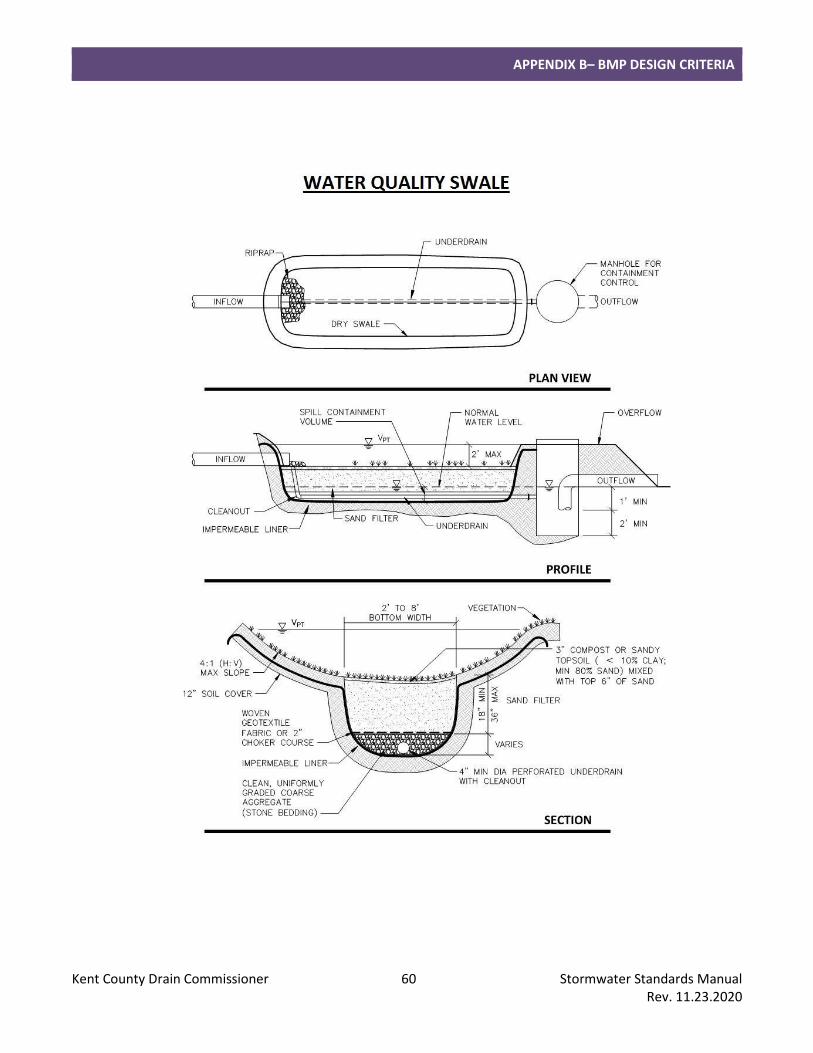
APPENDIX B– BMP DESIGN CRITERIA
Kent County Drain Commissioner 60 Stormwater Standards Manual Rev. 11.23.2020
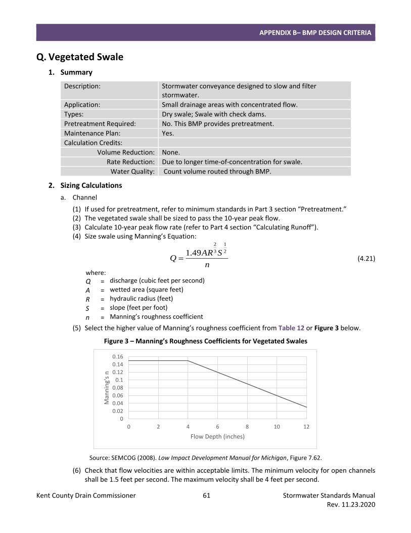
APPENDIX B– BMP DESIGN CRITERIA
Kent County Drain Commissioner 61 Stormwater Standards Manual Rev. 11.23.2020
Q. Vegetated Swale
1. Summary
Description: Stormwater conveyance designed to slow and filter stormwater.
Application: Small drainage areas with concentrated flow.
Types: Dry swale; Swale with check dams.
Pretreatment Required: No. This BMP provides pretreatment.
Maintenance Plan: Yes.
Calculation Credits:
Volume Reduction: None.
Rate Reduction: Due to longer time-of-concentration for swale.
Water Quality: Count volume routed through BMP.
2. Sizing Calculations
a. Channel
(1) If used for pretreatment, refer to minimum standards in Part 3 section “Pretreatment.” (2) The vegetated swale shall be sized to pass the 10-year peak flow. (3) Calculate 10-year peak flow rate (refer to Part 4 section “Calculating Runoff”). (4) Size swale using Manning’s Equation:
n
SARQ
2
1
3
2
49.1= (4.21)
where: Q = discharge (cubic feet per second)
A = wetted area (square feet)
R = hydraulic radius (feet)
S = slope (feet per foot)
n = Manning’s roughness coefficient
(5) Select the higher value of Manning’s roughness coefficient from Table 12 or Figure 3 below.
Figure 3 – Manning’s Roughness Coefficients for Vegetated Swales
Source: SEMCOG (2008). Low Impact Development Manual for Michigan, Figure 7.62.
(6) Check that flow velocities are within acceptable limits. The minimum velocity for open channels shall be 1.5 feet per second. The maximum velocity shall be 4 feet per second.
0
0.02
0.04
0.06
0.08
0.1
0.12
0.14
0.16
0 2 4 6 8 10 12
Man
nin
g's
n
Flow Depth (inches)
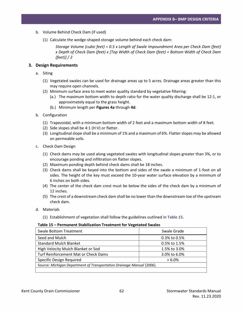
APPENDIX B– BMP DESIGN CRITERIA
Kent County Drain Commissioner 62 Stormwater Standards Manual Rev. 11.23.2020
b. Volume Behind Check Dam (if used)
(1) Calculate the wedge-shaped storage volume behind each check dam:
Storage Volume (cubic feet) = 0.5 x Length of Swale Impoundment Area per Check Dam (feet) x Depth of Check Dam (feet) x [Top Width of Check Dam (feet) + Bottom Width of Check Dam (feet)] / 2
3. Design Requirements
a. Siting
(1) Vegetated swales can be used for drainage areas up to 5 acres. Drainage areas greater than this may require open channels.
(2) Minimum surface area to meet water quality standard by vegetative filtering: (a.) The maximum bottom width to depth ratio for the water quality discharge shall be 12:1, or
approximately equal to the grass height. (b.) Minimum length per Figures 4a through 4d.
b. Configuration
(1) Trapezoidal, with a minimum bottom width of 2 feet and a maximum bottom width of 8 feet. (2) Side slopes shall be 4:1 (H:V) or flatter. (3) Longitudinal slope shall be a minimum of 1% and a maximum of 6%. Flatter slopes may be allowed
on permeable soils.
c. Check Dam Design
(1) Check dams may be used along vegetated swales with longitudinal slopes greater than 3%, or to encourage ponding and infiltration on flatter slopes.
(2) Maximum ponding depth behind check dams shall be 18 inches. (3) Check dams shall be keyed into the bottom and sides of the swale a minimum of 1-foot on all
sides. The height of the key must exceed the 10-year water surface elevation by a minimum of 6 inches on both sides.
(4) The center of the check dam crest must be below the sides of the check dam by a minimum of 12 inches.
(5) The crest of a downstream check dam shall be no lower than the downstream toe of the upstream check dam.
d. Materials
(1) Establishment of vegetation shall follow the guidelines outlined in Table 15.
Table 15 – Permanent Stabilization Treatment for Vegetated Swales
Swale Bottom Treatment Swale Grade
Seed and Mulch 0.3% to 0.5%
Standard Mulch Blanket 0.5% to 1.5%
High Velocity Mulch Blanket or Sod 1.5% to 3.0%
Turf Reinforcement Mat or Check Dams 3.0% to 6.0%
Specific Design Required > 6.0% Source: Michigan Department of Transportation Drainage Manual (2006).
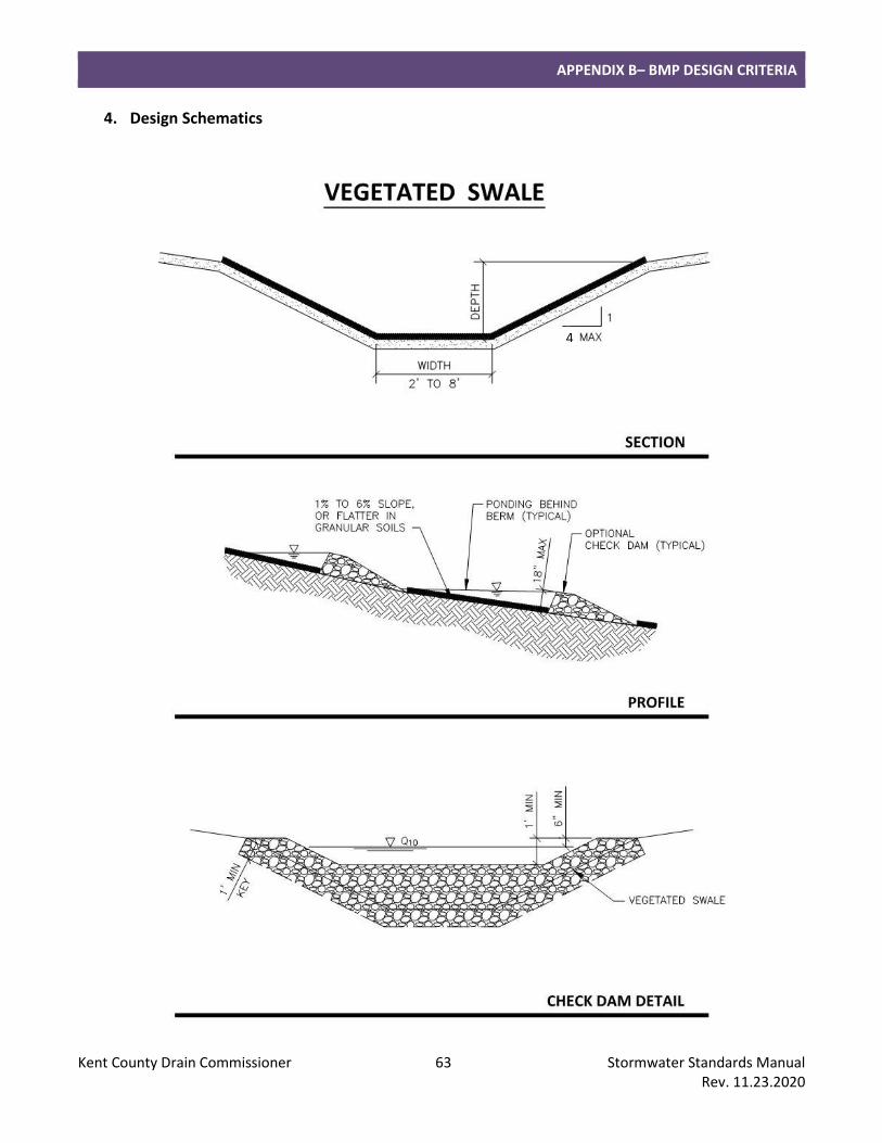
APPENDIX B– BMP DESIGN CRITERIA
Kent County Drain Commissioner 63 Stormwater Standards Manual Rev. 11.23.2020
4. Design Schematics
APPENDIX B– BMP DESIGN CRITERIA
Kent County Drain Commissioner 64 Stormwater Standards Manual Rev. 11.23.2020
R. Vegetated Filter Strip
1. Summary
Description: Overland flow path designed to slow and filter stormwater.
Application: Contributing drainage areas with sheet flow surface runoff.
Types: Turf grass; other dense herbaceous groundcover vegetation.
Pretreatment Required: No. This BMP provides pretreatment.
Maintenance Plan: Yes.
Calculation Credits:
Volume Reduction: None.
Rate Reduction: Adjust time-of-concentration.
Water Quality:
2. Sizing Calculations
a. If used for pretreatment, refer to minimum standards in Part 3 section “Pretreatment.”
b. Calculate the minimum required filter strip area by the equation:
6
AAfs = (4.27)
where: Afs = area of filter strip (square feet) A = contributing drainage area (square feet)
Note: This equates to a loading ratio of 0.17 from the contributing drainage area (both impervious and pervious surfaces).
c. Calculate minimum required longitudinal length based on slope and type of vegetation using the graphs in Figures 4a through 4d.
3. Design Requirements
a. Siting
(1) Maximum upstream drainage area shall generally be 100 feet impervious or 200 feet pervious upgradient.
b. Configuration
(1) The upstream edge of the filter strip shall be level and at an elevation at least 1 inch below the adjacent pavement.
(2) A level spreader may also be required to evenly distribute flow across filter strip.
(3) Slopes shall range from a minimum of 1% to a maximum of 8%. Optimal slopes range from 2% to 6%.
(4) The maximum lateral slope shall be 1%.
(5) Berms and curbs may be installed along the sides of the filter strip parallel to the direction of flow to prohibit runoff from laterally bypassing the filter strip.
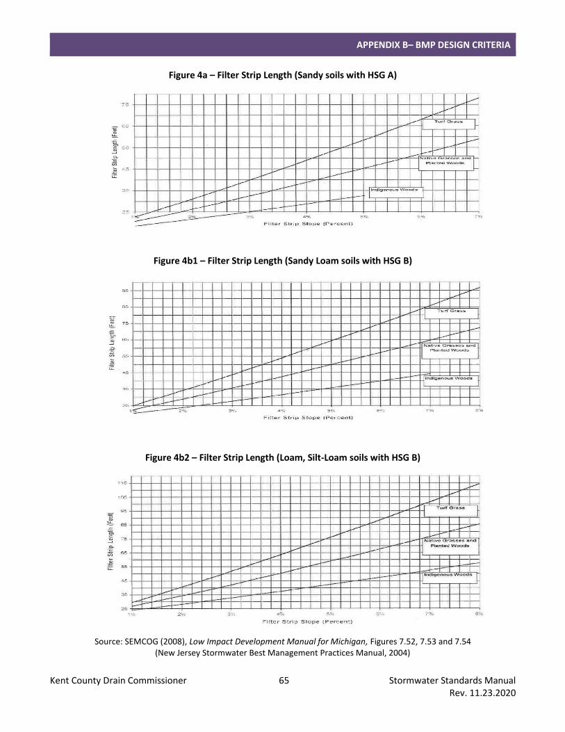
APPENDIX B– BMP DESIGN CRITERIA
Kent County Drain Commissioner 65 Stormwater Standards Manual Rev. 11.23.2020
Figure 4a – Filter Strip Length (Sandy soils with HSG A)
Figure 4b1 – Filter Strip Length (Sandy Loam soils with HSG B)
Figure 4b2 – Filter Strip Length (Loam, Silt-Loam soils with HSG B)
Source: SEMCOG (2008), Low Impact Development Manual for Michigan, Figures 7.52, 7.53 and 7.54 (New Jersey Stormwater Best Management Practices Manual, 2004)
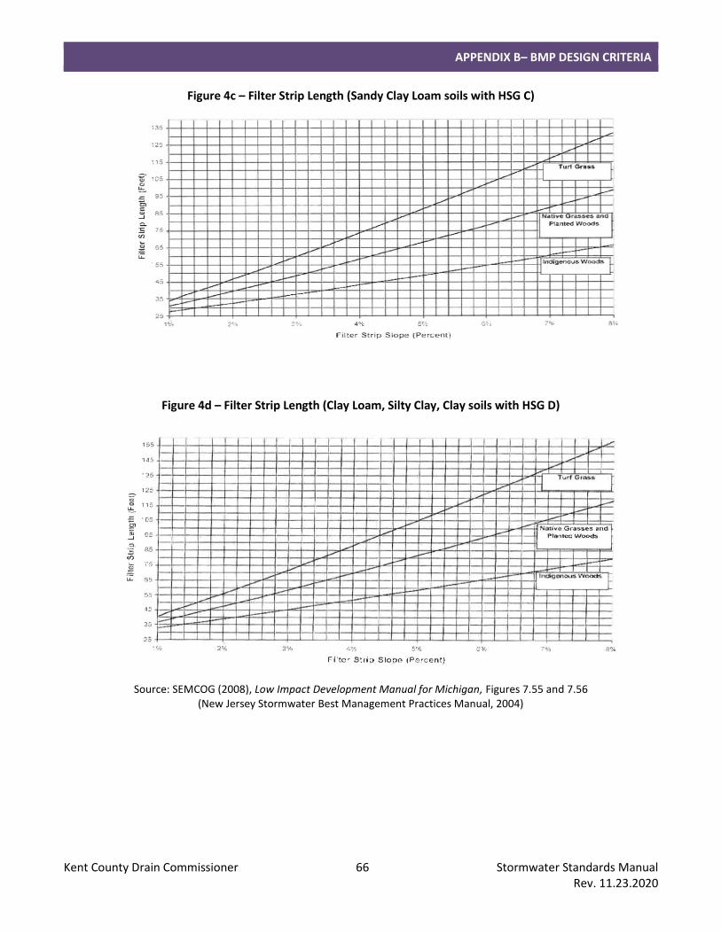
APPENDIX B– BMP DESIGN CRITERIA
Kent County Drain Commissioner 66 Stormwater Standards Manual Rev. 11.23.2020
Figure 4c – Filter Strip Length (Sandy Clay Loam soils with HSG C)
Figure 4d – Filter Strip Length (Clay Loam, Silty Clay, Clay soils with HSG D)
Source: SEMCOG (2008), Low Impact Development Manual for Michigan, Figures 7.55 and 7.56 (New Jersey Stormwater Best Management Practices Manual, 2004)
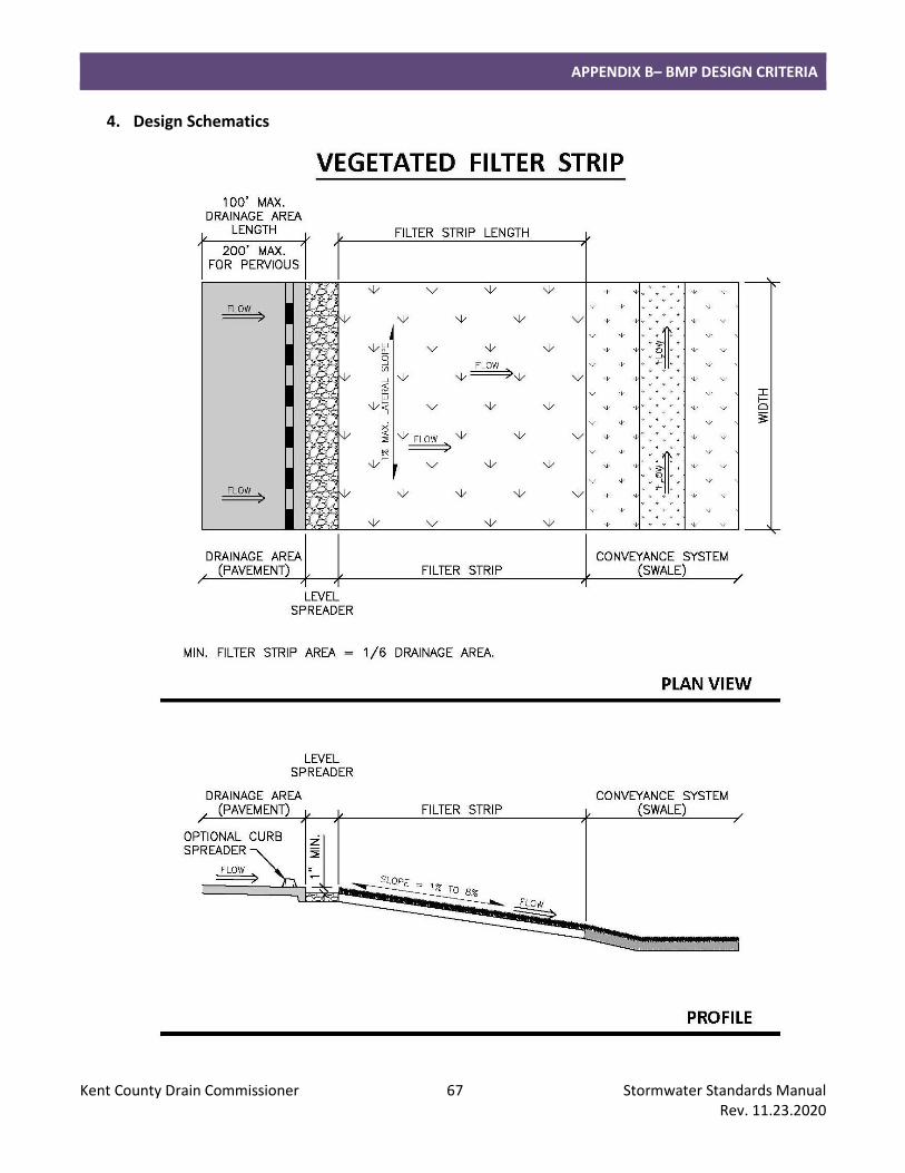
APPENDIX B– BMP DESIGN CRITERIA
Kent County Drain Commissioner 67 Stormwater Standards Manual Rev. 11.23.2020
4. Design Schematics
APPENDIX B– BMP DESIGN CRITERIA
Kent County Drain Commissioner 68 Stormwater Standards Manual Rev. 11.23.2020
S. Level Spreader
1. Summary
Description: Shallow, level berm placed perpendicular to a flow path.
Application: Used with other BMPs to disperse concentrated stormwater flows.
Types: Inflow (prior to BMP); Outflow (at outlet of BMP).
Pretreatment Required: No. This BMP provides pretreatment.
Maintenance Plan: Yes.
Calculation Credits:
Volume Reduction: None.
Rate Reduction: None.
Water Quality: None.
2. Sizing Calculations
a. The level spreader shall be sized to pass the 10-year peak flow.
b. Calculate 10-year peak flow rate (refer to Part 4 section “Calculating Runoff”).
3. Design Requirements
a. Siting
(1) Slopes below outflow level spreaders should be no greater than 8% in the direction of flow to discourage channelization.
b. Configuration
(1) Construct level spreaders in compacted fill or of other non-erodible material.
(2) Minimum length: 10 feet.
(3) A bypass may be required for higher flows.
c. Material
(1) Level spreaders may be constructed of compacted earth, rock, stone, concrete, treated timber or perforated pipe in stone.