Embed Size (px)
Citation preview
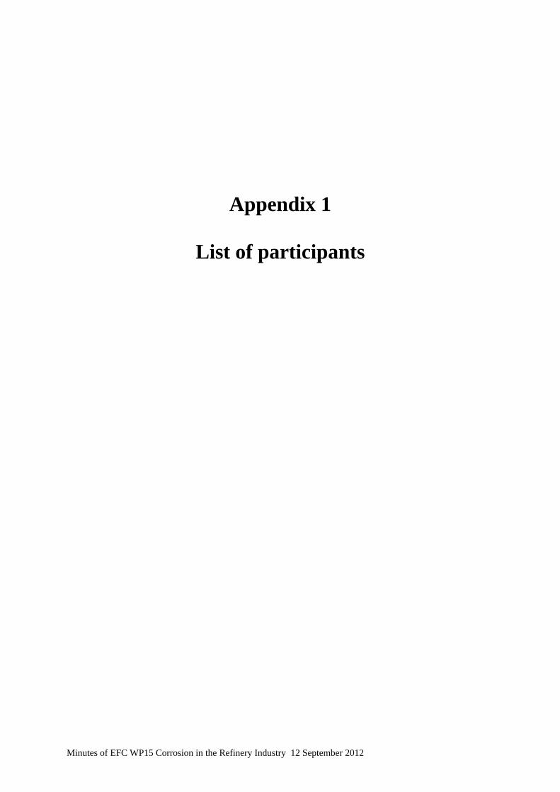
Appendix 1
List of participants
Minutes of EFC WP15 Corrosion in the Refinery Industry 12 September 2012
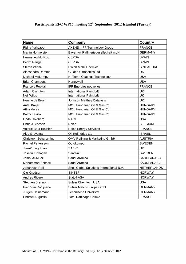
Participants EFC WP15 meeting 12th September 2012 Istanbul (Turkey)
Name Company Country Ridha Yahyaoui AXENS - IFP Technology Group FRANCE Martin Hofmeister Bayernoil Raffineriegesellschaft mbH GERMANY Hermenegildo Ruiz CEPSA SPAIN Pedro Rangel CEPSA SPAIN Stefan Winnik Exxon Mobil Chemical SINGAPORE Alessandro Demma Guided Ultrasonics Ltd UK Michael MeLampy Hi-Temp Coatings Technology USA Brian Chambers Honeywell USA Francois Ropital IFP Energies nouvelles FRANCE Adam Ovington International Paint Ldt UK Neil Wilds International Paint Ldt UK Hennie de Bruyn Johnson Matthey Catalysts UK Antal Krójer MOL Hungarian Oil & Gas Co HUNGARY Attila Veres MOL Hungarian Oil & Gas Co HUNGARY Baldy Laszlo MOL Hungarian Oil & Gas Co HUNGARY Linda Goldberg NACE USA Chris J Claesen Nalco BELGIUM Valerie Bour Beucler Nalco Energy Services FRANCE Alec Groysman Oil Refineries Ltd ISRAEL Christoph Scharsching OMV Refining & Marketing GmbH AUSTRIA Rachel Pettersson Outokumpu SWEDEN Jian-Zhong Zhang SABIC UK Josefin Eidhagen Sandvik SWEDEN Jamal Al-Muailu Saudi Aramco SAUDI ARABIA Mohammad Bokhari Saudi Aramco SAUDI ARABIA Johan van Roij Shell Global Solutions International B.V. NETHERLANDS Ole Knudsen SINTEF NORWAY Andres Rivero Statoil ASA NORWAY Stephen Brennom Sulzer Chemtech USA USA Fred Van Rodijnene Sulzer Metco Europe GmbH GERMANY Jurgen Heinemann Technische Universtat GERMANY Christel Augustin Total Raffinage Chimie FRANCE
Minutes of EFC WP15 Corrosion in the Refinery Industry 12 September 2012
Appendix 2
EFC WP15 Activities
(Francois Ropital)
Minutes of EFC WP15 Corrosion in the Refinery Industry 12 September 2012
1
EFC WP15 Annual meeting 12 September 2012 Istanbul - Turkey 1
European Federation of Corrosion (EFC)European Federation of Corrosion (EFC)
•• Federation of 31 National Associations
• 20 Working Parties (WP)
• Annual Corrosion congress « Eurocorr »
• Thematic workshops and symposiums
• Working Party meetings (for WP15 twice a year)
• Publications
• EFC - NACE agreement (20% discount on books price)
• for more information http://www.efcweb.org
Presentation of the activities of WP15
EFC WP15 Annual meeting 12 September 2012 Istanbul - Turkey 2
EFC Working Party 15 « Corrosion in Refinery » Activities
Who is an EFC member
To be an EFC member you (individually or your company, university) has to be member of one of 31 national EFC "member societies“ or member of a affiliate member. Your company or university can now also an affiliate member.
For example:in Norway: Norsk Korrojonstekniske Foreningin France: Cefracor or Federation Française de Chimiein Germany: Dechema or GfKORRin UK: Institute of Corrosion or IOM or NACE Europein Israel: CAMPI or Israel Corrosion Forumin Poland: Polish Corrosion Society.................You will find all these information on www.efcweb.org or in the EFC Newsletter
Benefits to be an EFC member:- 20% discount on EFC Publications and NACE Publications-reduction at the Eurocorr conference-access the new EFC web restricted pages (papers of the previous EurocorrConference) via your national corrosion society web pages
2
EFC WP15 Annual meeting 12 September 2012 Istanbul - Turkey 3
EFC Working Parties
•• WP 1: Corrosion InhibitionWP 1: Corrosion Inhibition•• WP 3: High Temperature WP 3: High Temperature •• WP 4: Nuclear CorrosionWP 4: Nuclear Corrosion•• WP 5: Environmental Sensitive FractureWP 5: Environmental Sensitive Fracture•• WP 6: Surface Science and Mechanisms of corrosion and protectioWP 6: Surface Science and Mechanisms of corrosion and protectionn•• WP 7: EducationWP 7: Education•• WP 8: TestingWP 8: Testing•• WP 9: Marine CorrosionWP 9: Marine Corrosion•• WP 10: Microbial CorrosionWP 10: Microbial Corrosion•• WP 11: Corrosion of reinforcement in concreteWP 11: Corrosion of reinforcement in concrete•• WP 12: Computer based information systemsWP 12: Computer based information systems•• WP 13: Corrosion in oil and gas productionWP 13: Corrosion in oil and gas production•• WP 14: CoatingsWP 14: Coatings• WP 15: Corrosion in the refinery industry
(created in sept. 96 with John Harston as first chairman)•• WP 16: WP 16: CathodicCathodic protectionprotection•• WP 17: AutomotiveWP 17: Automotive•• WP 18: WP 18: TribocorrosionTribocorrosion•• WP 19: Corrosion of polymer materialsWP 19: Corrosion of polymer materials•• WP 20: Corrosion by drinking watersWP 20: Corrosion by drinking waters•• WP 21: Corrosion of archaeological and historical artefactsWP 21: Corrosion of archaeological and historical artefacts
http://www.efcweb.org
•• A task force on CO2 Capture and Sequestration (CCS)
EFC WP15 Annual meeting 12 September 2012 Istanbul - Turkey 4
EFC Working Party 15 « Corrosion in Refinery » Activities
Chairman: Francois Ropital Vice Chairman: Hennie de Bruyn
The following are the main areas being pursued by the Working Party:
Information ExchangeSharing of refinery materials /corrosion experiences by operating company representatives.Possibility to have a restricted web page on the EFC-WP15 page
Forum for TechnologySharing materials/ corrosion/ protection/ monitoring information by providers
Eurocorr Conferences
WP MeetingsOne WP 15 working party meeting in Spring, One meeting at Eurocorr in September in conjunction with the conference,
Publications - Guidelines
http://www.efcweb.org/Working+Parties-p-104085/WP%2B15-p-104111.html

3
EFC WP15 Annual meeting 12 September 2012 Istanbul - Turkey 5
Publications from WP15
• EFC Guideline n°40 « Prevention of corrosion by cooling waters » available from http://www.woodheadpublishing.com/en/book.aspx?bookID=1193Update in relation with Nace document 11106 "Monitoring and adjustment of cooling water treatment operating parameters" Task Group 152 on cooling water systems
• EFC Guideline n° 46 on corrosion in amine unitshttp://www.woodheadpublishing.com/en/book.aspx?bookID=1299
•EFC Guideline n° 42 Collection of selected papershttp://www.woodheadpublishing.com/en/book.aspx?bookID=1295
•EFC Guideline n° 55 Corrosion Under Insulationhttp://www.woodheadpublishing.com/en/book.aspx?bookID=1486
•Future publications : suggestions ?• best practice guideline to avoid and characterize stress relaxation cracking ?
EFC WP15 Annual meeting 12 September 2012 Istanbul - Turkey 6
EFC Working Party 15 plan work 2011-2013
. Collaboration with Nace : exchange of minutes of meetings"NACE TEG 205X information exchange -corrosion in refineries "
. Sessions with other EFC WP at Eurocorr (2013 in Estoril-Portugal, 2014 Pisa-Italy) on which topics?
• Update of publications• CUI guideline• Amine acid gas treatment plants
• New Publications: best practice guideline to avoid and characterize stress relaxation cracking ?
• Education – qualification – certificationList of "corrosion refinery" related courses on EFC website ?
4
EFC WP15 Annual meeting 12 September 2012 Istanbul - Turkey 7
EFC Working Party 15 plan work 2011-2013
EFC WP15 Annual meeting 12 September 2012 Istanbul - Turkey 8
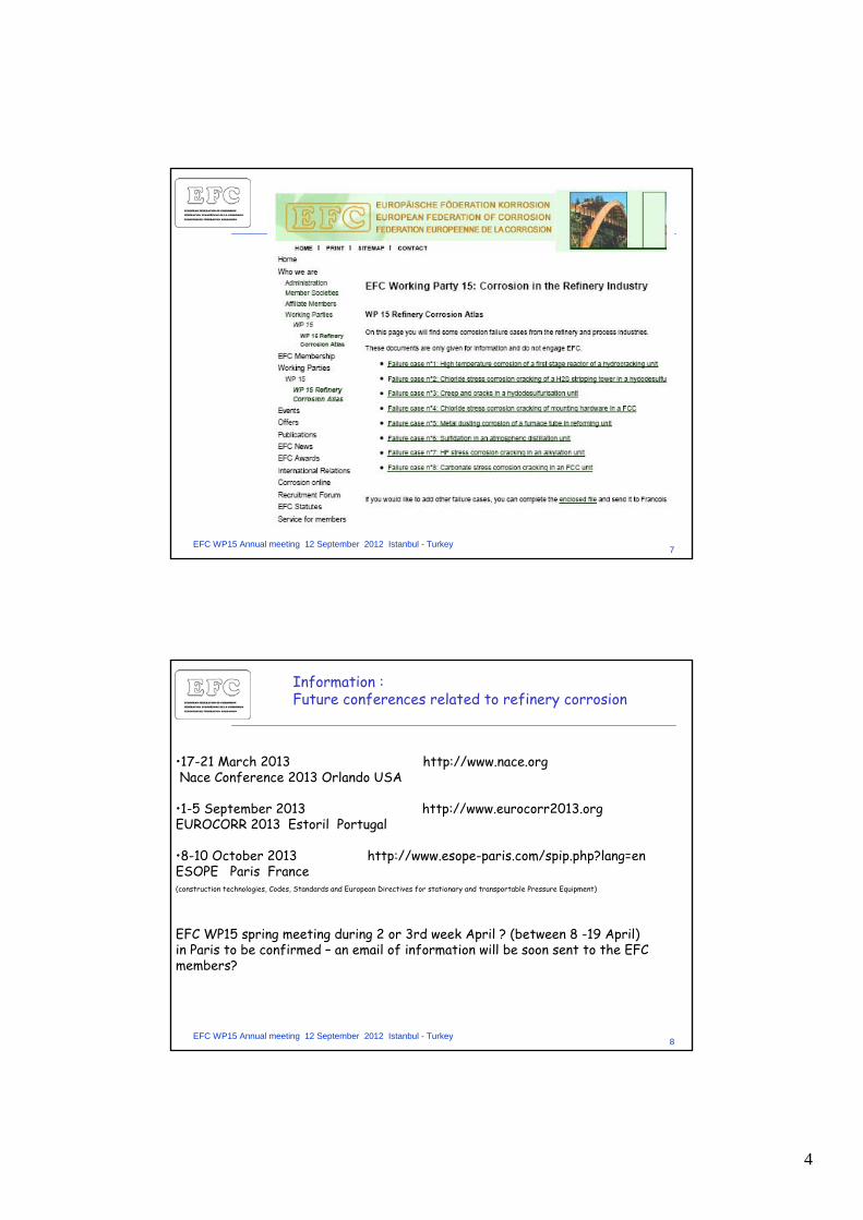
Information : Future conferences related to refinery corrosion
•17-21 March 2013 http://www.nace.orgNace Conference 2013 Orlando USA
•1-5 September 2013 http://www.eurocorr2013.orgEUROCORR 2013 Estoril Portugal
•8-10 October 2013 http://www.esope-paris.com/spip.php?lang=enESOPE Paris France (construction technologies, Codes, Standards and European Directives for stationary and transportable Pressure Equipment)
EFC WP15 spring meeting during 2 or 3rd week April ? (between 8 -19 April)in Paris to be confirmed – an email of information will be soon sent to the EFC members?
Appendix 3
CUI- Honeywell JIP Proposal
(B. Chambers - Honeywell)
Minutes of EFC WP15 Corrosion in the Refinery Industry 12 September 2012
Characterization and Quantification of Corrosion Under Insulation (CUI) for Process Plant
Applications
Review of Joint Industry Program Proposal
Presentation by:Brian Chambers, Ph.D.
Vishal LagadSridhar Srinivasan
2CUI JIP
Corrosion Under Insulation - An Introduction
Occurs under coverings, e.g. thermal insulation, fireproofing and jacketed vessels and piping
Occurs in process equipment operating over a wide range of conditions:- Carbon and low alloy steels- Stainless steels (PREN < 40)- Temperature range: -4C to 150 C- Refineries, petrochemical & power plants, industrial facilities (both onshore and
offshore).
Actual metal loss rates are dependent on a number of factors - Amount, duration, orientation and frequency of wetness- Chloride or other chemical contamination, presence of industrial pollutants, leachability of
corrodents from the insulation- Operating temperature and - Wet-dry cyclic operation
Despite existing standards (NACE/EFC), the incidences of CUI appearsto be occurring at an increasing rate. Mainly in existing construction.
Despite existing standards (NACE/EFC), the incidences of CUI appearsto be occurring at an increasing rate. Mainly in existing construction.
3CUI JIP
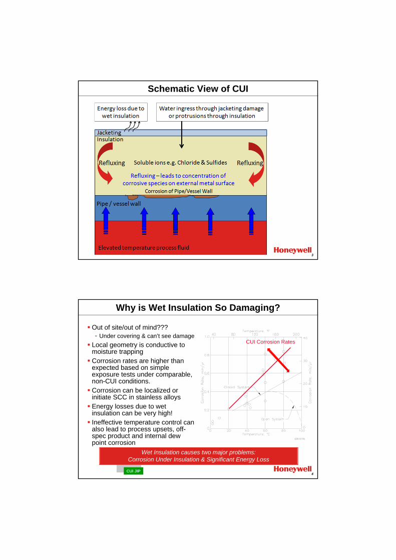
Schematic View of CUI
4CUI JIP
Why is Wet Insulation So Damaging?
Out of site/out of mind???- Under covering & can’t see damage
Local geometry is conductive to moisture trappingCorrosion rates are higher than expected based on simple exposure tests under comparable, non-CUI conditions.Corrosion can be localized or initiate SCC in stainless alloysEnergy losses due to wet insulation can be very high!Ineffective temperature control can also lead to process upsets, off-spec product and internal dew point corrosion
CUI Corrosion Rates
Wet Insulation causes two major problems:Corrosion Under Insulation & Significant Energy Loss
5CUI JIP
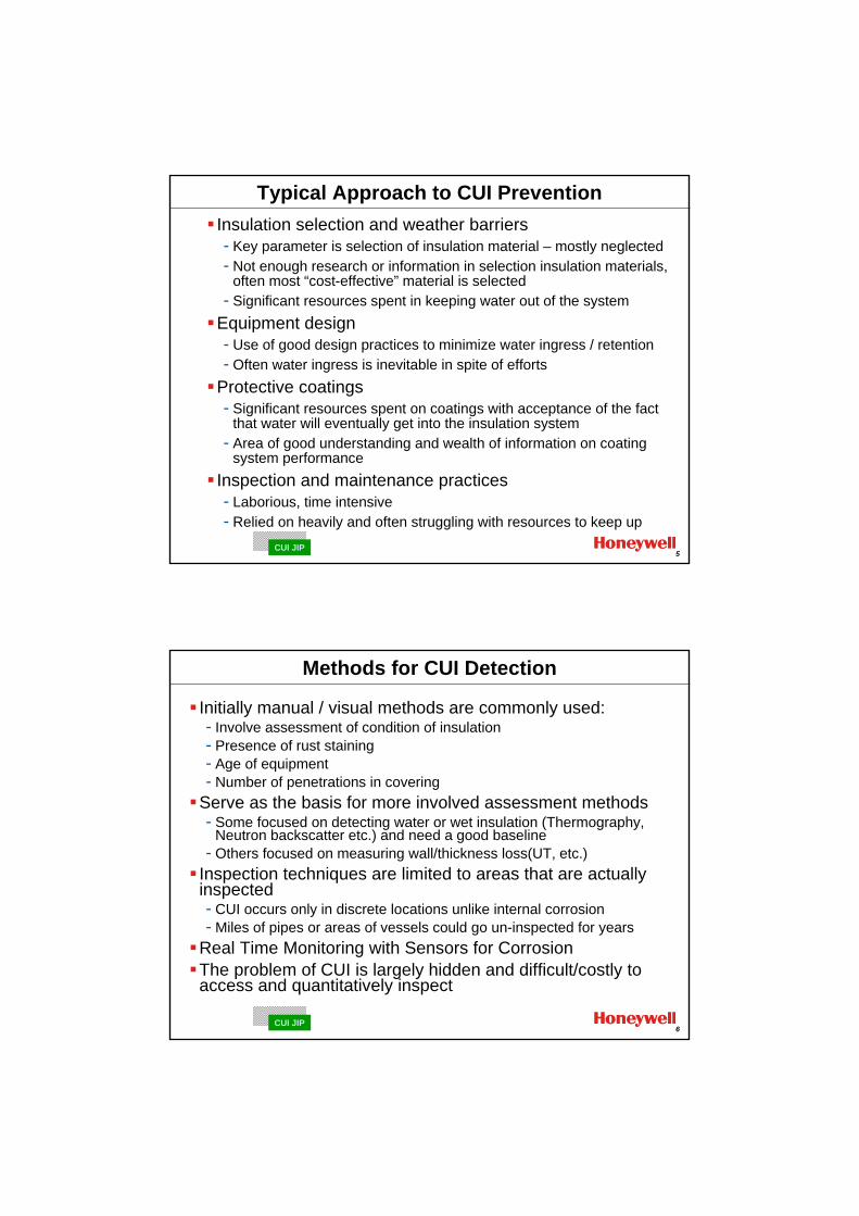
Typical Approach to CUI PreventionInsulation selection and weather barriers - Key parameter is selection of insulation material – mostly neglected- Not enough research or information in selection insulation materials,
often most “cost-effective” material is selected- Significant resources spent in keeping water out of the system
Equipment design - Use of good design practices to minimize water ingress / retention- Often water ingress is inevitable in spite of efforts
Protective coatings - Significant resources spent on coatings with acceptance of the fact
that water will eventually get into the insulation system- Area of good understanding and wealth of information on coating
system performanceInspection and maintenance practices - Laborious, time intensive- Relied on heavily and often struggling with resources to keep up
6CUI JIP
Methods for CUI Detection
Initially manual / visual methods are commonly used:- Involve assessment of condition of insulation- Presence of rust staining- Age of equipment- Number of penetrations in covering
Serve as the basis for more involved assessment methods- Some focused on detecting water or wet insulation (Thermography,
Neutron backscatter etc.) and need a good baseline- Others focused on measuring wall/thickness loss(UT, etc.)
Inspection techniques are limited to areas that are actually inspected - CUI occurs only in discrete locations unlike internal corrosion- Miles of pipes or areas of vessels could go un-inspected for years
Real Time Monitoring with Sensors for Corrosion The problem of CUI is largely hidden and difficult/costly to access and quantitatively inspect
7CUI JIP
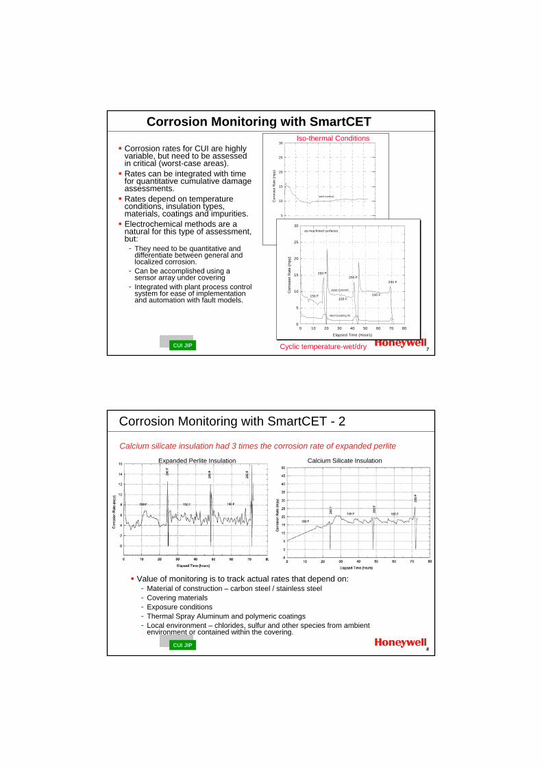
Corrosion Monitoring with SmartCET
Corrosion rates for CUI are highly variable, but need to be assessed in critical (worst-case areas).Rates can be integrated with time for quantitative cumulative damage assessments.Rates depend on temperature conditions, insulation types, materials, coatings and impurities.Electrochemical methods are a natural for this type of assessment, but:- They need to be quantitative and
differentiate between general and localized corrosion.
- Can be accomplished using a sensor array under covering
- Integrated with plant process control system for ease of implementation and automation with fault models.
Elapsed Time (Hours)
0 10 20 30 40 50 60 70 80
Cor
rosi
on R
ate
(mpy
)
0
5
10
15
20
25
30
steel (control)
steel (coating A)
Iso-thermal Conditions
Elapsed Time (Hours)
0 10 20 30 40 50 60 70 80
Cor
rosi
on R
ate
(mpy
)
0
5
10
15
20
25
30
steel (control)
steel (coating A)
250 F250 F
250 F
150 F150 F
150 F
as-machined surfaces
Elapsed Time (Hours)
0 10 20 30 40 50 60 70 80
Cor
rosi
on R
ate
(mpy
)
0
5
10
15
20
25
30
steel (control)
steel (coating A)
250 F250 F
250 F
150 F150 F
150 F
as-machined surfaces
Cyclic temperature-wet/dry
8CUI JIP
Value of monitoring is to track actual rates that depend on:- Material of construction – carbon steel / stainless steel- Covering materials- Exposure conditions- Thermal Spray Aluminum and polymeric coatings- Local environment – chlorides, sulfur and other species from ambient
environment or contained within the covering.
Calcium Silicate InsulationExpanded Perlite Insulation
Calcium silicate insulation had 3 times the corrosion rate of expanded perlite
Corrosion Monitoring with SmartCET - 2
9CUI JIP
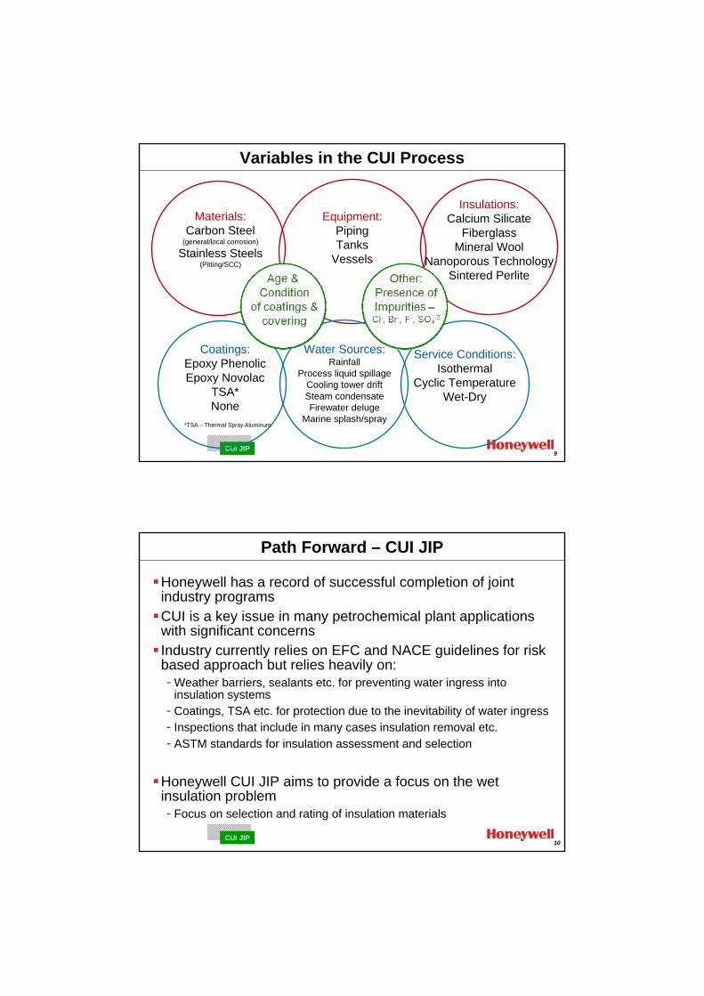
Materials:Carbon Steel
(general/local corrosion)
Stainless Steels(Pitting/SCC)
Equipment:PipingTanks
Vessels
Insulations:Calcium Silicate
FiberglassMineral Wool
Nanoporous TechnologySintered Perlite
Water Sources:Rainfall
Process liquid spillageCooling tower driftSteam condensateFirewater deluge
Marine splash/spray
Coatings:Epoxy PhenolicEpoxy Novolac
TSA*None
*TSA – Thermal Spray Aluminum
Service Conditions:Isothermal
Cyclic TemperatureWet-Dry
Variables in the CUI Process
10CUI JIP
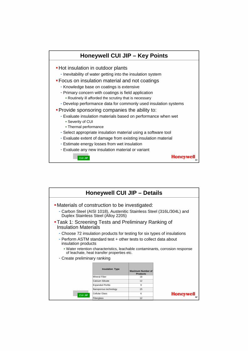
Path Forward – CUI JIP
Honeywell has a record of successful completion of joint industry programs CUI is a key issue in many petrochemical plant applications with significant concernsIndustry currently relies on EFC and NACE guidelines for risk based approach but relies heavily on:- Weather barriers, sealants etc. for preventing water ingress into
insulation systems- Coatings, TSA etc. for protection due to the inevitability of water ingress- Inspections that include in many cases insulation removal etc.- ASTM standards for insulation assessment and selection
Honeywell CUI JIP aims to provide a focus on the wet insulation problem- Focus on selection and rating of insulation materials
11CUI JIP
Honeywell CUI JIP – Key Points
Hot insulation in outdoor plants- Inevitability of water getting into the insulation system
Focus on insulation material and not coatings- Knowledge base on coatings is extensive- Primary concern with coatings is field application
Routinely ill afforded the scrutiny that is necessary - Develop performance data for commonly used insulation systems
Provide sponsoring companies the ability to:- Evaluate insulation materials based on performance when wet
Severity of CUIThermal performance
- Select appropriate insulation material using a software tool- Evaluate extent of damage from existing insulation material- Estimate energy losses from wet insulation- Evaluate any new insulation material or variant
12CUI JIP
Honeywell CUI JIP – Details
Materials of construction to be investigated: - Carbon Steel (AISI 1018), Austenitic Stainless Steel (316L/304L) and
Duplex Stainless Steel (Alloy 2205)Task 1: Screening Tests and Preliminary Ranking of Insulation Materials- Choose 72 insulation products for testing for six types of insulations- Perform ASTM standard test + other tests to collect data about
insulation productsWater retention characteristics, leachable contaminants, corrosion response of leachate, heat transfer properties etc.
- Create preliminary ranking
Insulation TypeMaximum Number of
ProductsMineral Fiber 18
Calcium Silicate 12
Expanded Perlite 9
Nanoporous technology 15
Cellular Glass 6
Fiberglass 12
13CUI JIP
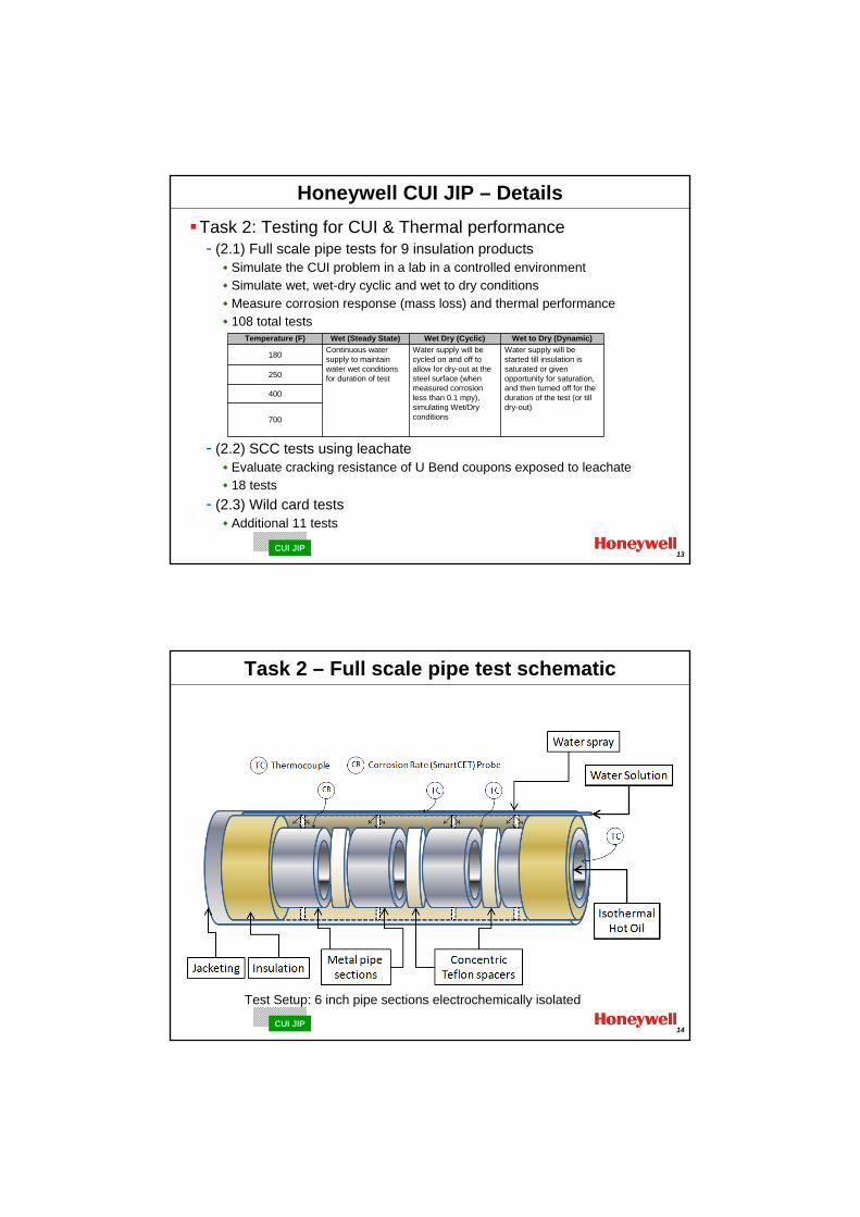
Honeywell CUI JIP – DetailsTask 2: Testing for CUI & Thermal performance- (2.1) Full scale pipe tests for 9 insulation products
Simulate the CUI problem in a lab in a controlled environmentSimulate wet, wet-dry cyclic and wet to dry conditionsMeasure corrosion response (mass loss) and thermal performance108 total tests
- (2.2) SCC tests using leachateEvaluate cracking resistance of U Bend coupons exposed to leachate18 tests
- (2.3) Wild card testsAdditional 11 tests
Temperature (F) Wet (Steady State) Wet Dry (Cyclic) Wet to Dry (Dynamic)
180 Continuous water supply to maintain water wet conditions for duration of test
Water supply will be cycled on and off to allow for dry-out at the steel surface (when measured corrosion less than 0.1 mpy), simulating Wet/Dry conditions
Water supply will be started till insulation is saturated or given opportunity for saturation, and then turned off for the duration of the test (or till dry-out)
250
400
700
14CUI JIP
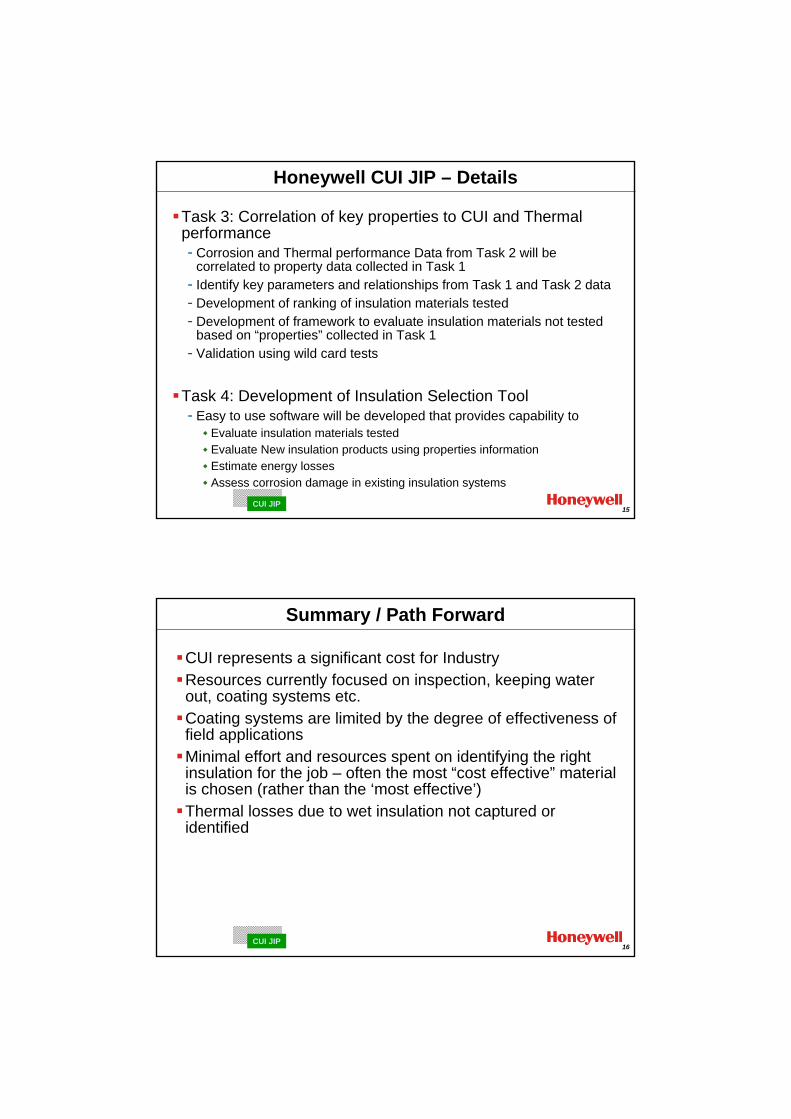
Task 2 – Full scale pipe test schematic
Test Setup: 6 inch pipe sections electrochemically isolated
15CUI JIP
Honeywell CUI JIP – Details
Task 3: Correlation of key properties to CUI and Thermal performance- Corrosion and Thermal performance Data from Task 2 will be
correlated to property data collected in Task 1- Identify key parameters and relationships from Task 1 and Task 2 data- Development of ranking of insulation materials tested- Development of framework to evaluate insulation materials not tested
based on “properties” collected in Task 1- Validation using wild card tests
Task 4: Development of Insulation Selection Tool- Easy to use software will be developed that provides capability to
Evaluate insulation materials testedEvaluate New insulation products using properties informationEstimate energy lossesAssess corrosion damage in existing insulation systems
16CUI JIP
Summary / Path Forward
CUI represents a significant cost for IndustryResources currently focused on inspection, keeping water out, coating systems etc.Coating systems are limited by the degree of effectiveness of field applicationsMinimal effort and resources spent on identifying the right insulation for the job – often the most “cost effective” material is chosen (rather than the ‘most effective’)Thermal losses due to wet insulation not captured or identified

17CUI JIP
Summary / Path Forward - 2
Utilize JIP approach to develop necessary data to support development of a CUI software tool for - Ranking available insulation products based on corrosion and thermal
performance- Assessment of CUI damage in plant piping - Demonstrate efficacy of real time monitoring technology as a basis for field
installation- Evaluation of energy losses due to wet insulation- Evaluation of any insulation materials and compare with others
Develop an unbiased set of data to rank and select insulation materials and assess corrosion damage and thermal losses due to existing wet insulation
Appendix 4
CUI – SINTEF JIP Proposal
(O. Knudsen – SINTEF)
Minutes of EFC WP15 Corrosion in the Refinery Industry 12 September 2012
SINTEF Materials and Chemistry
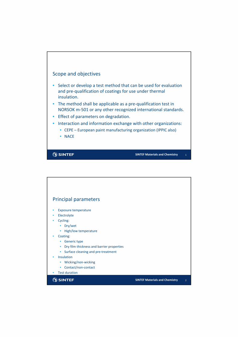
Scope and objectives
1
• Select or develop a test method that can be used for evaluation and pre‐qualification of coatings for use under thermal insulation.
• The method shall be applicable as a pre‐qualification test in NORSOK m‐501 or any other recognized international standards.
• Effect of parameters on degradation.
• Interaction and information exchange with other organizations:• CEPE – European paint manufacturing organization (IPPIC also)
• NACE
SINTEF Materials and Chemistry
• Exposure temperature
• Electrolyte
• Cycling:
• Dry/wet
• High/low temperature
• Coating:
• Generic type
• Dry film thickness and barrier properties
• Surface cleaning and pre‐treatment
• Insulation
• Wicking/non‐wicking
• Contact/non‐contact
• Test duration
2
Principal parameters

SINTEF Materials and Chemistry
• WP1: State of art
• State of art concerning Coatings Under Insulation and test methods
• Agree on a range of conditions that represent the problem
• WP2: Test and apparatus development
• Agree on methodology
• Build apparatus
• WP3: Evaluation of the test method and investigate parameters
• Test a limited set of coatings under different conditions. References: TSA, uncoated steel, zinc silicate.
• Evaluate and correlate
• Modify apparatus and methodology
• WP4: Finalizing the method
• Determine the parameters
• Testing a set of coatings with the final procedure
3
Work description
SINTEF Materials and Chemistry
State of art
4
• CUI – a short summary of some facts
• NACE SP198‐2010: Control of Corrosion Under Thermal Insulation and Fireproofing Materials—A Systems Approach
• EFC 55 "Corrosion‐under‐insulation (CUI) guidelines"
• ASTM G189 ‐ Standard Guide for Laboratory Simulation of Corrosion Under Insulation
• ASTM D2485 – Standard Test Method for Evaluating Coatings For High Temperature Service
• Previous projects with focus on test method• Hydro 1995‐1997 (Jan Ivar Skar)
• Statoil 2010 (Kristian Haraldsen)
• International Paint 2005‐2012
SINTEF Materials and Chemistry
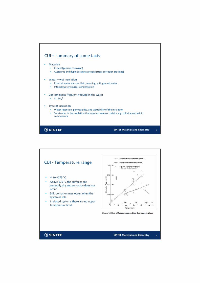
CUI – summary of some facts
5
• Materials • C‐steel (general corrosion)• Austenitic and duplex Stainless steels (stress corrosion cracking)
• Water – wet insulation• External water sources: Rain, washing, spill, ground water …• Internal water source: Condensation
• Contaminants frequently found in the water• Cl‐, SO4
2‐
• Type of insulation• Water retention, permeability, and wettability of the insulation• Substances in the insulation that may increase corrosivity, e.g. chloride and acidic
components
SINTEF Materials and Chemistry 6
CUI ‐ Temperature range
• ‐4 to +175 °C
• Above 175 °C the surfaces are generally dry and corrosion does not occur
• Still, corrosion may occur when the system is idle
• In closed systems there are no upper temperature limit
SINTEF Materials and Chemistry 7
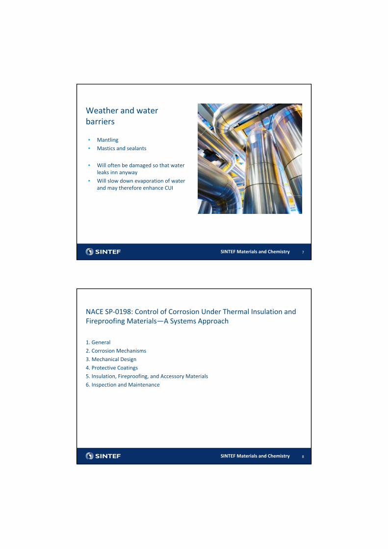
Weather and water barriers
• Mantling
• Mastics and sealants
• Will often be damaged so that water leaks inn anyway
• Will slow down evaporation of water and may therefore enhance CUI
SINTEF Materials and Chemistry
1. General
2. Corrosion Mechanisms
3. Mechanical Design
4. Protective Coatings
5. Insulation, Fireproofing, and Accessory Materials
6. Inspection and Maintenance
8
NACE SP‐0198: Control of Corrosion Under Thermal Insulation and Fireproofing Materials—A Systems Approach
SINTEF Materials and Chemistry
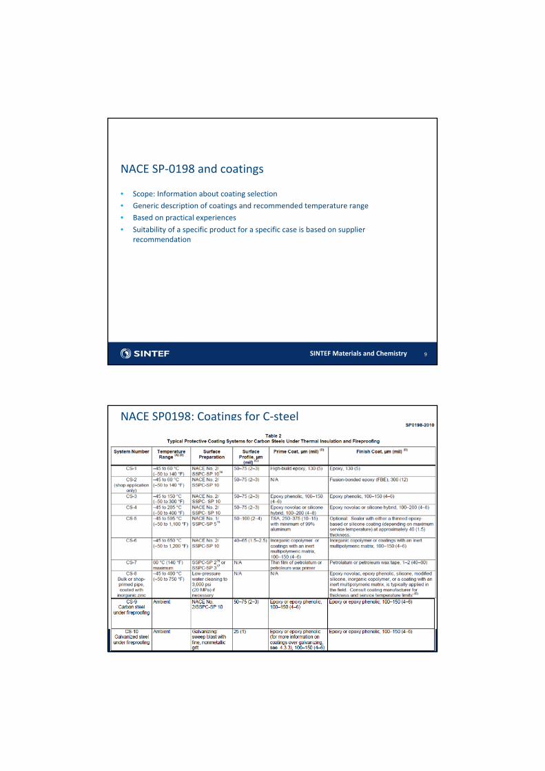
• Scope: Information about coating selection
• Generic description of coatings and recommended temperature range
• Based on practical experiences
• Suitability of a specific product for a specific case is based on supplier recommendation
9
NACE SP‐0198 and coatings
SINTEF Materials and Chemistry 10
NACE SP0198: Coatings for C‐steel
SINTEF Materials and Chemistry 11
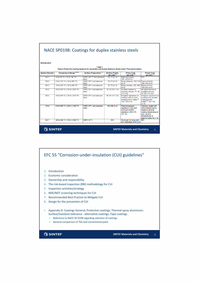
NACE SP0198: Coatings for duplex stainless steels
SINTEF Materials and Chemistry
EFC 55 "Corrosion‐under‐insulation (CUI) guidelines"
12
1. Introduction
2. Economic consideration
3. Ownership and responsibility
4. The risk‐based inspection (RBI) methodology for CUI
5. Inspection activities/strategy
6. NDE/NDT screening techniques for CUI
7. Recommended Best Practice to Mitigate CUI
8. Design for the prevention of CUI
• Appendix D: Coatings General; Protective coatings; Thermal spray aluminium; Surface/moisture tolerance ‐ alternative coatings; Tape coatings. • Reference to NACE SP‐0198 regarding selection of coatings
• General comparison of TSA and conventional paint
SINTEF Materials and Chemistry 13
TSA vs conventional paint
SINTEF Materials and Chemistry
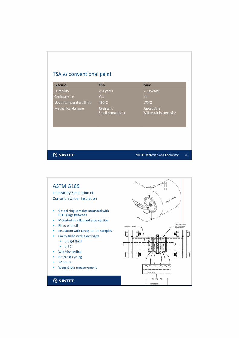
• 6 steel ring samples mounted with PTFE rings between
• Mounted in a flanged pipe section
• Filled with oil
• Insulation with cavity to the samples
• Cavity filled with electrolyte
• 0.5 g/l NaCl
• pH 6
• Wet/dry cycling
• Hot/cold cycling
• 72 hours
• Weight loss measurement
14
ASTM G189Laboratory Simulation of
Corrosion Under Insulation
SINTEF Materials and Chemistry
• Primarily a corrosion test for comparison of corrosion rate for different types of steel
• In my view the test is similar to a simple immersion test
• Has been used for testing of a coating (CORROSION/97, paper #266)
• The coating quality was evaluated by steel corrosion rate
• Will only be a measure of % surface area damaged
• The ring samples are too small for testing of coatings
• Not really suitable for coating evaluation as described
15
ASTM G189
SINTEF Materials and Chemistry
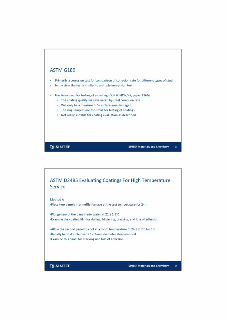
Method A
•Place two panels in a muffle furnace at the test temperature for 24 h
•Plunge one of the panels into water at 21 ± 2.5°C•Examine the coating film for dulling, blistering, cracking, and loss of adhesion
•Allow the second panel to cool at a room temperature of 24 ± 2.5°C for 1 h
•Rapidly bend double over a 12.7‐mm diameter steel mandrel
•Examine this panel for cracking and loss of adhesion
16
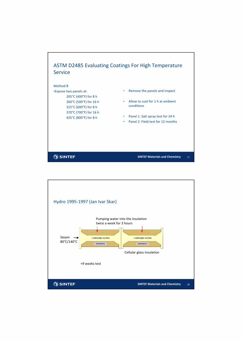
ASTM D2485 Evaluating Coatings For High Temperature Service
SINTEF Materials and Chemistry
Method B
•Expose two panels at:205°C (400°F) for 8 h
260°C (500°F) for 16 h
315°C (600°F) for 8 h
370°C (700°F) for 16 h
425°C (800°F) for 8 h
17
ASTM D2485 Evaluating Coatings For High Temperature Service
• Remove the panels and inspect
• Allow to cool for 1 h at ambient conditions
• Panel 1: Salt spray test for 24 h
• Panel 2: Field test for 12 months
SINTEF Materials and Chemistry
Hydro 1995‐1997 (Jan Ivar Skar)
18
Pumping water into the insulationtwice a week for 3 hours
Steam80°C/140°C
Cellular glass insulation
+9 weeks test
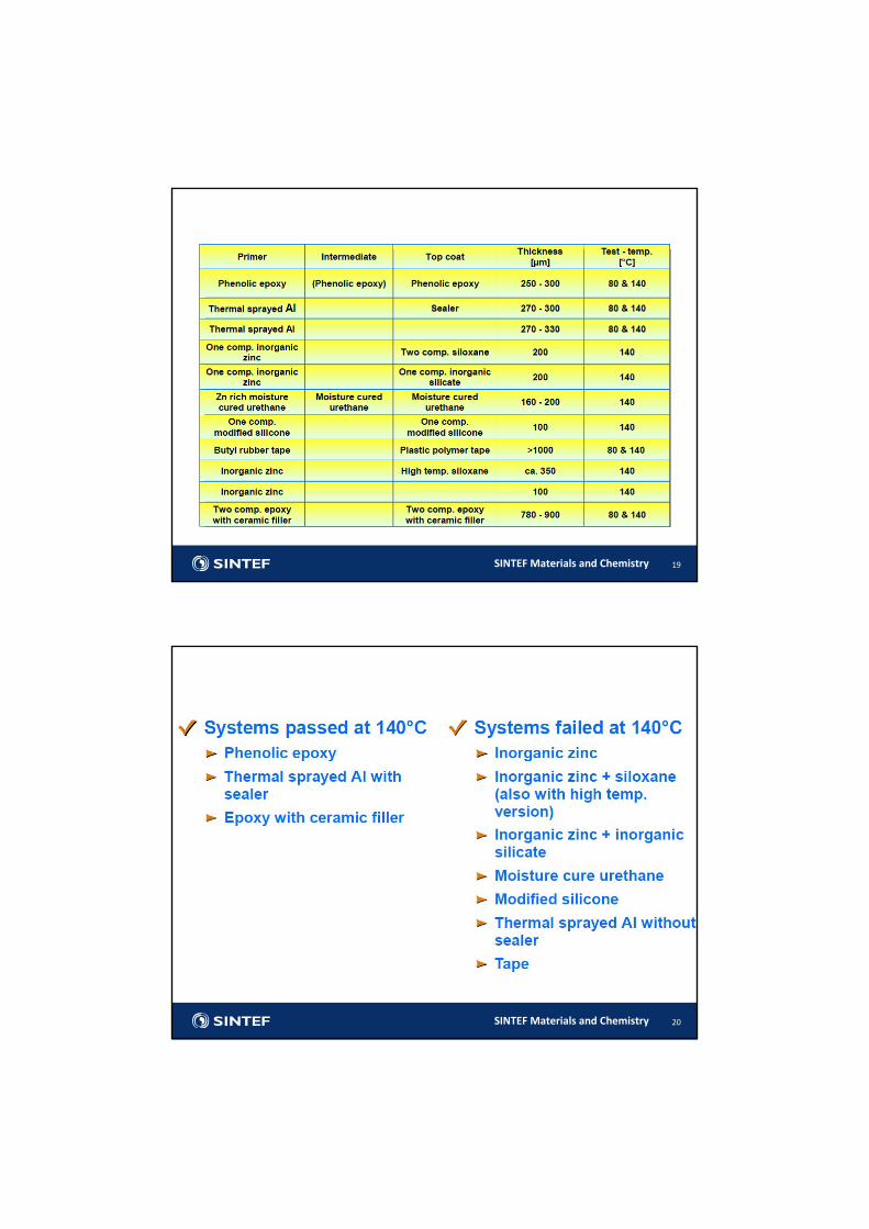
SINTEF Materials and Chemistry 19
SINTEF Materials and Chemistry 20
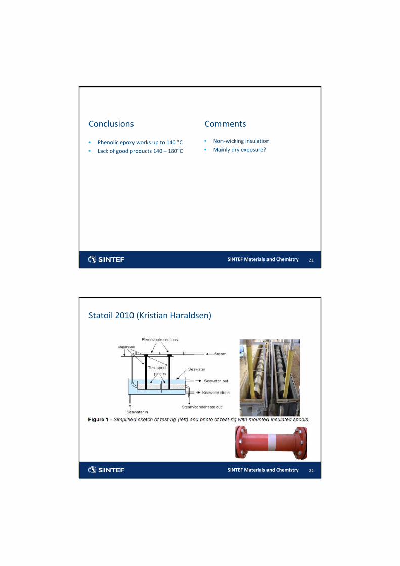
SINTEF Materials and Chemistry
• Phenolic epoxy works up to 140 °C
• Lack of good products 140 – 180°C
21
Conclusions Comments
• Non‐wicking insulation
• Mainly dry exposure?
SINTEF Materials and Chemistry
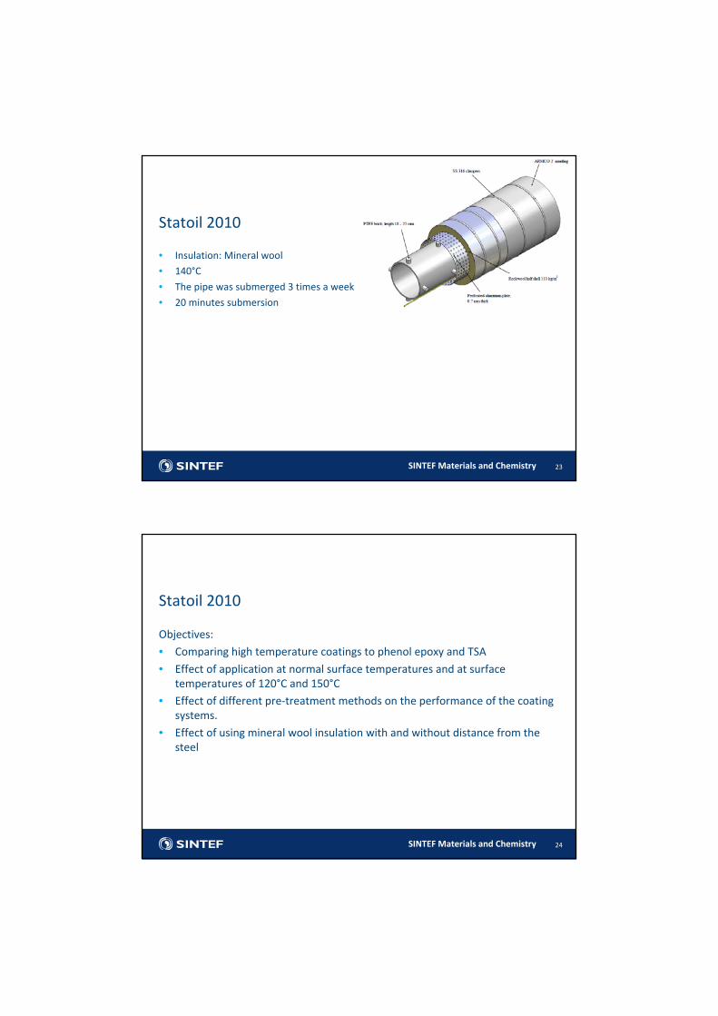
Statoil 2010 (Kristian Haraldsen)
22
SINTEF Materials and Chemistry
Statoil 2010
23
• Insulation: Mineral wool
• 140°C
• The pipe was submerged 3 times a week
• 20 minutes submersion
SINTEF Materials and Chemistry
Statoil 2010
24
Objectives:• Comparing high temperature coatings to phenol epoxy and TSA
• Effect of application at normal surface temperatures and at surface temperatures of 120°C and 150°C
• Effect of different pre‐treatment methods on the performance of the coating systems.
• Effect of using mineral wool insulation with and without distance from the steel
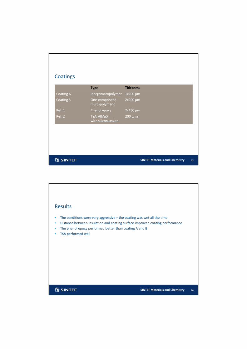
SINTEF Materials and Chemistry 25
Coatings
SINTEF Materials and Chemistry
Results
26
• The conditions were very aggressive – the coating was wet all the time
• Distance between insulation and coating surface improved coating performance
• The phenol epoxy performed better than coating A and B
• TSA performed well
SINTEF Materials and Chemistry
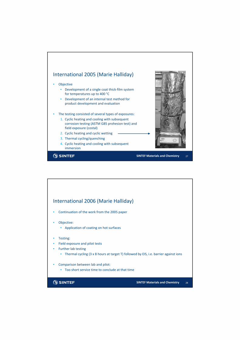
• Objective
• Development of a single coat thick‐film system for temperatures up to 400 °C
• Development of an internal test method for product development and evaluation
• The testing consisted of several types of exposures:
1. Cyclic heating and cooling with subsequent corrosion testing (ASTM G85 prohesion test) and field exposure (costal)
2. Cyclic heating and cyclic wetting
3. Thermal cycling/quenching
4. Cyclic heating and cooling with subsequent immersion
27
International 2005 (Marie Halliday)
SINTEF Materials and Chemistry
• Continuation of the work from the 2005 paper
• Objective:
• Application of coating on hot surfaces
• Testing:
• Field exposure and pilot tests
• Further lab testing
• Thermal cycling (3 x 8 hours at target T) followed by EIS, i.e. barrier against ions
• Comparison between lab and pilot:
• Too short service time to conclude at that time
28
International 2006 (Marie Halliday)
SINTEF Materials and Chemistry
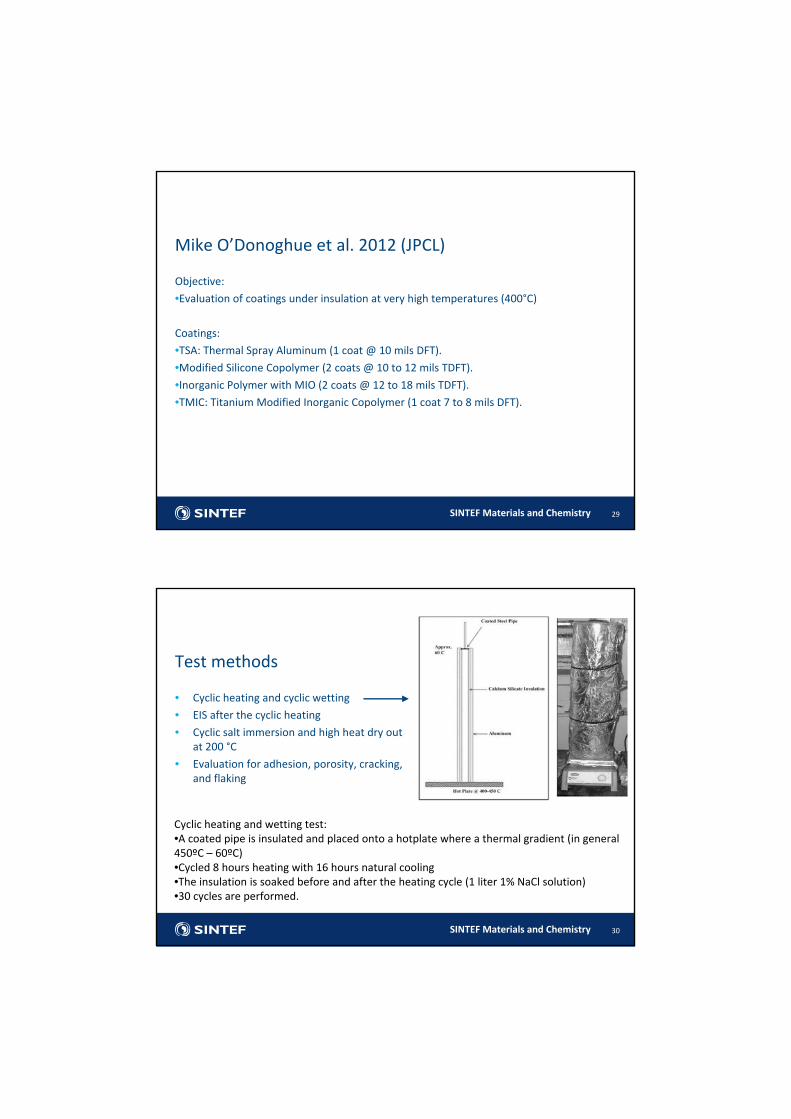
Objective:
•Evaluation of coatings under insulation at very high temperatures (400°C)
Coatings:
•TSA: Thermal Spray Aluminum (1 coat @ 10 mils DFT).
•Modified Silicone Copolymer (2 coats @ 10 to 12 mils TDFT).
•Inorganic Polymer with MIO (2 coats @ 12 to 18 mils TDFT).
•TMIC: Titanium Modified Inorganic Copolymer (1 coat 7 to 8 mils DFT).
29
Mike O’Donoghue et al. 2012 (JPCL)
SINTEF Materials and Chemistry
• Cyclic heating and cyclic wetting
• EIS after the cyclic heating
• Cyclic salt immersion and high heat dry out at 200 °C
• Evaluation for adhesion, porosity, cracking, and flaking
30
Test methods
Cyclic heating and wetting test:•A coated pipe is insulated and placed onto a hotplate where a thermal gradient (in general 450ºC – 60ºC)•Cycled 8 hours heating with 16 hours natural cooling•The insulation is soaked before and after the heating cycle (1 liter 1% NaCl solution) •30 cycles are performed.
SINTEF Materials and Chemistry
• The paper focus mainly on coating performance and less on test correlation
• There seems to be a certain correlation: TSA and TMIC performed better than the inorganic polymers both in lab and field
31
Correlation with in service performance
SINTEF Materials and Chemistry
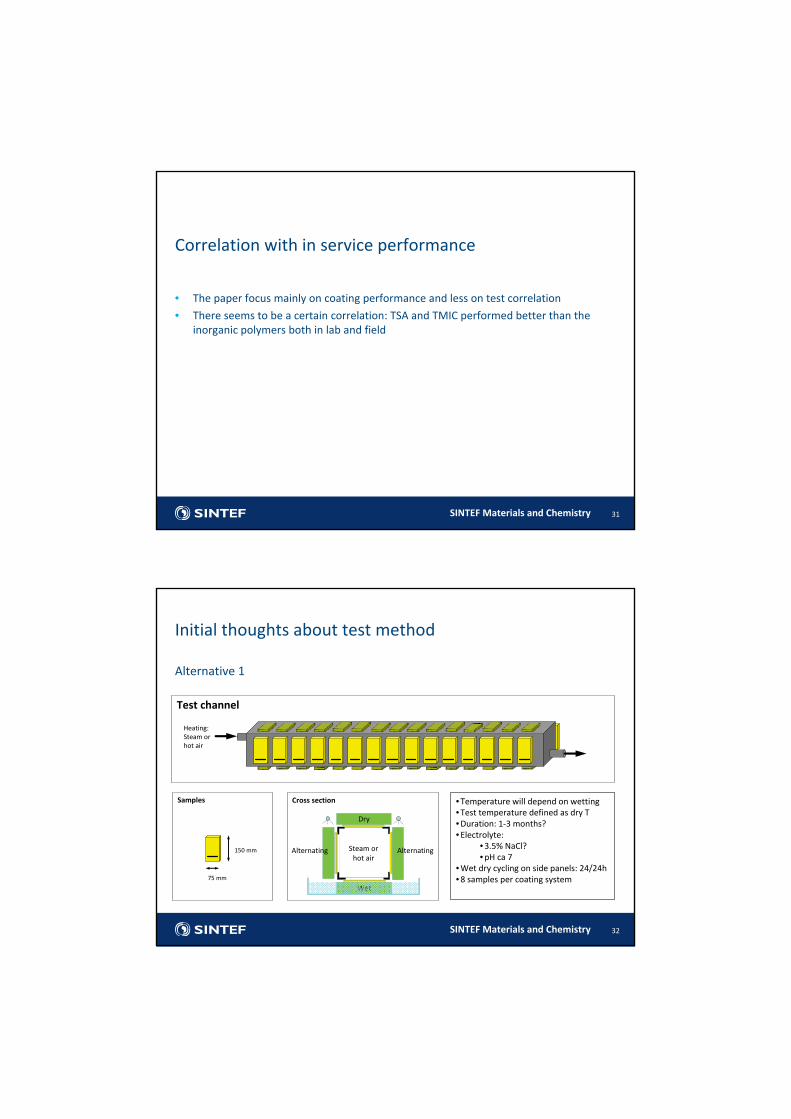
Initial thoughts about test method
Alternative 1
32
Heating: Steam or hot air
Steam or hot air
Wet
Dry
Alternating Alternating
Cross section
150 mm
75 mm
Samples
Test channel
•Temperature will depend on wetting•Test temperature defined as dry T•Duration: 1‐3 months?•Electrolyte:
•3.5% NaCl?•pH ca 7
•Wet dry cycling on side panels: 24/24h•8 samples per coating system
SINTEF Materials and Chemistry
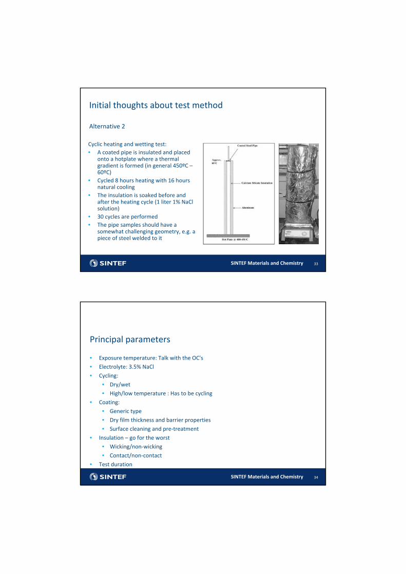
Initial thoughts about test method
Alternative 2
33
Cyclic heating and wetting test:• A coated pipe is insulated and placed
onto a hotplate where a thermal gradient is formed (in general 450ºC –60ºC)
• Cycled 8 hours heating with 16 hours natural cooling
• The insulation is soaked before and after the heating cycle (1 liter 1% NaClsolution)
• 30 cycles are performed• The pipe samples should have a
somewhat challenging geometry, e.g. a piece of steel welded to it
SINTEF Materials and Chemistry
• Exposure temperature: Talk with the OC's
• Electrolyte: 3.5% NaCl
• Cycling:
• Dry/wet
• High/low temperature : Has to be cycling
• Coating:
• Generic type
• Dry film thickness and barrier properties
• Surface cleaning and pre‐treatment
• Insulation – go for the worst
• Wicking/non‐wicking
• Contact/non‐contact
• Test duration
34
Principal parameters
SINTEF Materials and Chemistry 35
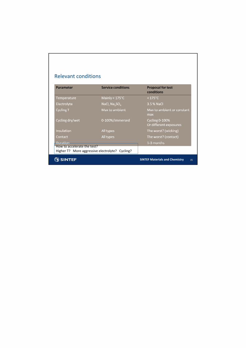
Relevant conditions
How to accelerate the test?Higher T? More aggressive electrolyte? Cycling?
Appendix 5
Crude units overhead systems
(B. Chambers - Honeywell)
Minutes of EFC WP15 Corrosion in the Refinery Industry 12 September 2012
Corrosion Characterization in Crude Distillation Unit Overhead
Systems – Phase I
Review of Joint Industry Program Proposal
Presentation by:Brian Chambers, Ph.D.
2CDU Overhead JIP
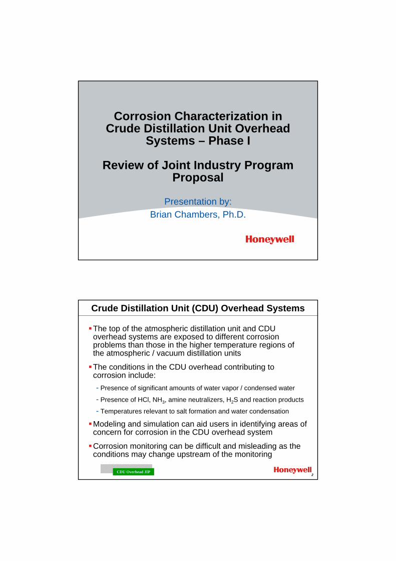
Crude Distillation Unit (CDU) Overhead Systems
The top of the atmospheric distillation unit and CDU overhead systems are exposed to different corrosion problems than those in the higher temperature regions of the atmospheric / vacuum distillation units
The conditions in the CDU overhead contributing to corrosion include:- Presence of significant amounts of water vapor / condensed water
- Presence of HCl, NH3, amine neutralizers, H2S and reaction products
- Temperatures relevant to salt formation and water condensation
Modeling and simulation can aid users in identifying areas of concern for corrosion in the CDU overhead system
Corrosion monitoring can be difficult and misleading as the conditions may change upstream of the monitoring
3CDU Overhead JIP
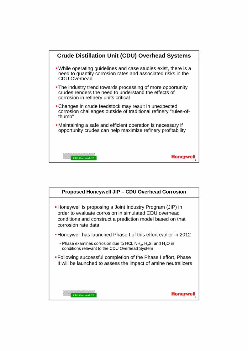
Crude Distillation Unit (CDU) Overhead Systems
While operating guidelines and case studies exist, there is a need to quantify corrosion rates and associated risks in the CDU Overhead
The industry trend towards processing of more opportunity crudes renders the need to understand the effects of corrosion in refinery units critical
Changes in crude feedstock may result in unexpected corrosion challenges outside of traditional refinery “rules-of-thumb”
Maintaining a safe and efficient operation is necessary if opportunity crudes can help maximize refinery profitability
4CDU Overhead JIP
Proposed Honeywell JIP – CDU Overhead Corrosion
Honeywell is proposing a Joint Industry Program (JIP) in order to evaluate corrosion in simulated CDU overhead conditions and construct a prediction model based on that corrosion rate data
Honeywell has launched Phase I of this effort earlier in 2012
- Phase examines corrosion due to HCl, NH3, H2S, and H2O in conditions relevant to the CDU Overhead System
Following successful completion of the Phase I effort, Phase II will be launched to assess the impact of amine neutralizers
5CDU Overhead JIP
Proposed Honeywell JIP – CDU Overhead Corrosion
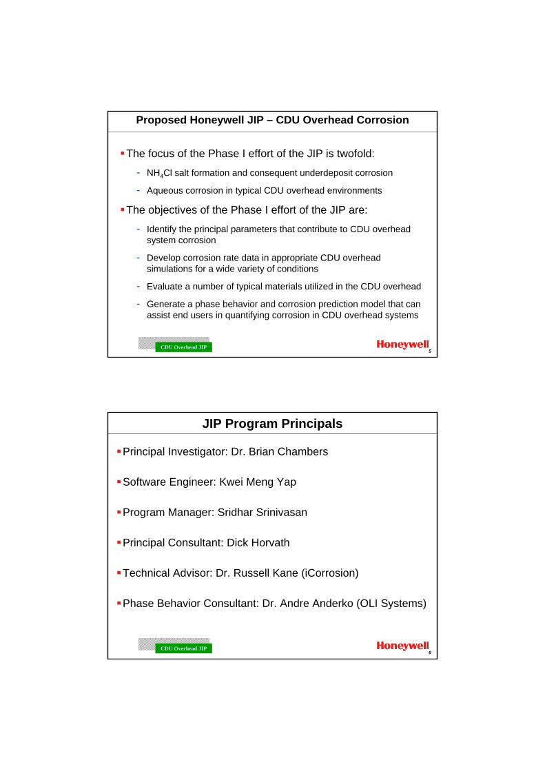
The focus of the Phase I effort of the JIP is twofold:
- NH4Cl salt formation and consequent underdeposit corrosion
- Aqueous corrosion in typical CDU overhead environments
The objectives of the Phase I effort of the JIP are:
- Identify the principal parameters that contribute to CDU overhead system corrosion
- Develop corrosion rate data in appropriate CDU overhead simulations for a wide variety of conditions
- Evaluate a number of typical materials utilized in the CDU overhead
- Generate a phase behavior and corrosion prediction model that can assist end users in quantifying corrosion in CDU overhead systems
6CDU Overhead JIP
JIP Program Principals
Principal Investigator: Dr. Brian Chambers
Software Engineer: Kwei Meng Yap
Program Manager: Sridhar Srinivasan
Principal Consultant: Dick Horvath
Technical Advisor: Dr. Russell Kane (iCorrosion)
Phase Behavior Consultant: Dr. Andre Anderko (OLI Systems)
7CDU Overhead JIP
Details of the Honeywell CDU Overhead JIP
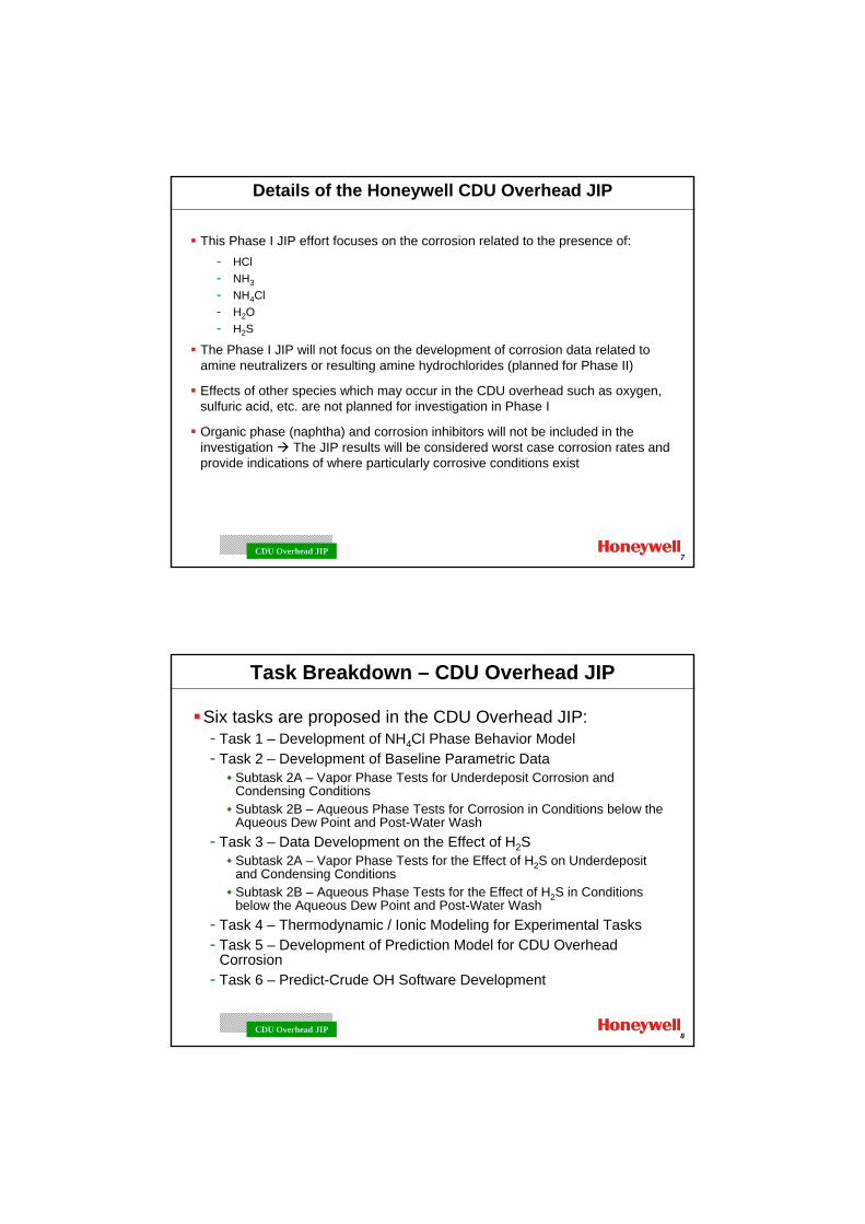
This Phase I JIP effort focuses on the corrosion related to the presence of:- HCl- NH3
- NH4Cl- H2O- H2S
The Phase I JIP will not focus on the development of corrosion data related to amine neutralizers or resulting amine hydrochlorides (planned for Phase II)
Effects of other species which may occur in the CDU overhead such as oxygen, sulfuric acid, etc. are not planned for investigation in Phase I
Organic phase (naphtha) and corrosion inhibitors will not be included in the investigation The JIP results will be considered worst case corrosion rates and provide indications of where particularly corrosive conditions exist
8CDU Overhead JIP
Task Breakdown – CDU Overhead JIP
Six tasks are proposed in the CDU Overhead JIP:- Task 1 – Development of NH4Cl Phase Behavior Model- Task 2 – Development of Baseline Parametric Data
Subtask 2A – Vapor Phase Tests for Underdeposit Corrosion and Condensing ConditionsSubtask 2B – Aqueous Phase Tests for Corrosion in Conditions below the Aqueous Dew Point and Post-Water Wash
- Task 3 – Data Development on the Effect of H2SSubtask 2A – Vapor Phase Tests for the Effect of H2S on Underdeposit and Condensing ConditionsSubtask 2B – Aqueous Phase Tests for the Effect of H2S in Conditions below the Aqueous Dew Point and Post-Water Wash
- Task 4 – Thermodynamic / Ionic Modeling for Experimental Tasks- Task 5 – Development of Prediction Model for CDU Overhead
Corrosion- Task 6 – Predict-Crude OH Software Development
9CDU Overhead JIP
Task 1 – Phase Behavior Model
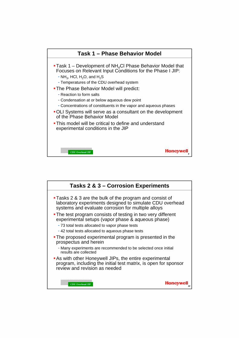
Task 1 – Development of NH4Cl Phase Behavior Model that Focuses on Relevant Input Conditions for the Phase I JIP:- NH3, HCl, H2O, and H2S- Temperatures of the CDU overhead system
The Phase Behavior Model will predict:- Reaction to form salts- Condensation at or below aqueous dew point- Concentrations of constituents in the vapor and aqueous phases
OLI Systems will serve as a consultant on the development of the Phase Behavior ModelThis model will be critical to define and understand experimental conditions in the JIP
10CDU Overhead JIP
Tasks 2 & 3 – Corrosion Experiments
Tasks 2 & 3 are the bulk of the program and consist of laboratory experiments designed to simulate CDU overhead systems and evaluate corrosion for multiple alloysThe test program consists of testing in two very different experimental setups (vapor phase & aqueous phase)- 73 total tests allocated to vapor phase tests- 42 total tests allocated to aqueous phase tests
The proposed experimental program is presented in the prospectus and herein- Many experiments are recommended to be selected once initial
results are collectedAs with other Honeywell JIPs, the entire experimental program, including the initial test matrix, is open for sponsor review and revision as needed
11CDU Overhead JIP
Materials for Evaluation
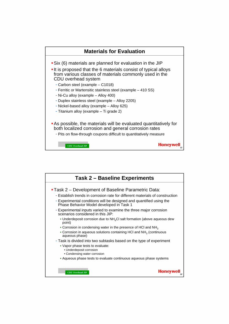
Six (6) materials are planned for evaluation in the JIPIt is proposed that the 6 materials consist of typical alloys from various classes of materials commonly used in the CDU overhead system- Carbon steel (example – C1018)- Ferritic or Martensitic stainless steel (example – 410 SS)- Ni-Cu alloy (example – Alloy 400)- Duplex stainless steel (example – Alloy 2205)- Nickel-based alloy (example – Alloy 625)- Titanium alloy (example – Ti grade 2)
As possible, the materials will be evaluated quantitatively for both localized corrosion and general corrosion rates- Pits on flow-through coupons difficult to quantitatively measure
12CDU Overhead JIP
Task 2 – Baseline Experiments
Task 2 – Development of Baseline Parametric Data:- Establish trends in corrosion rate for different materials of construction- Experimental conditions will be designed and quantified using the
Phase Behavior Model developed in Task 1 - Experimental inputs varied to examine the three major corrosion
scenarios considered in this JIP:Underdeposit corrosion due to NH4Cl salt formation (above aqueous dew point)Corrosion in condensing water in the presence of HCl and NH3Corrosion in aqueous solutions containing HCl and NH3 (continuous aqueous phase)
- Task is divided into two subtasks based on the type of experiment Vapor phase tests to evaluate:
• Underdeposit corrosion• Condensing water corrosion
Aqueous phase tests to evaluate continuous aqueous phase systems
13CDU Overhead JIP
Task 2A – Baseline Experiments (Vapor Phase)
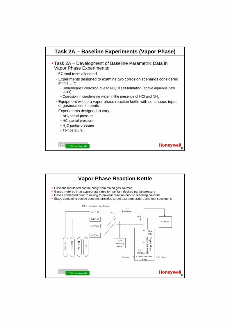
Task 2A – Development of Baseline Parametric Data in Vapor Phase Experiments:- 57 total tests allocated- Experiments designed to examine two corrosion scenarios considered
in this JIP:Underdeposit corrosion due to NH4Cl salt formation (above aqueous dew point)Corrosion in condensing water in the presence of HCl and NH3
- Equipment will be a vapor phase reaction kettle with continuous input of gaseous constituents
- Experiments designed to vary:NH3 partial pressureHCl partial pressureH2O partial pressureTemperature
14CDU Overhead JIP
Vapor Phase Reaction KettleGaseous inputs fed continuously from mixed gas sourcesGases metered in at appropriate rates to maintain desired partial pressureGases preheated prior to mixing to prevent reaction prior to reaching couponsStage containing cooled coupons provides target test temperature and test specimens
MFC #1
MFC #2
MFC#3
NH
3 + N2
HC
l + N2
H2 S + N
2
H2O metering
pump
Coolant CoolantCooled specimen stage
GasPre-heater
Scrubber
Vapor Phase
Reaction K
ettle
MFC – Metered Flow Control
MFC#4
N2
Gas Inlet
Gas Outlet
15CDU Overhead JIP
Test coupon(1of 6)
Thermowell
Coolant flowCoolant flow channel
Teflon
Teflon
Heat tape
Gas and condensate to scrubber
Lid
O-ring
Standard 6-in borosilicate glass shell with grooved flanges
Teflon coupon stage
Stainless steel base plate
Heated, mixed gas input
Thermowell
Coupon (cooled from flow channel beneath)
Thermocouple
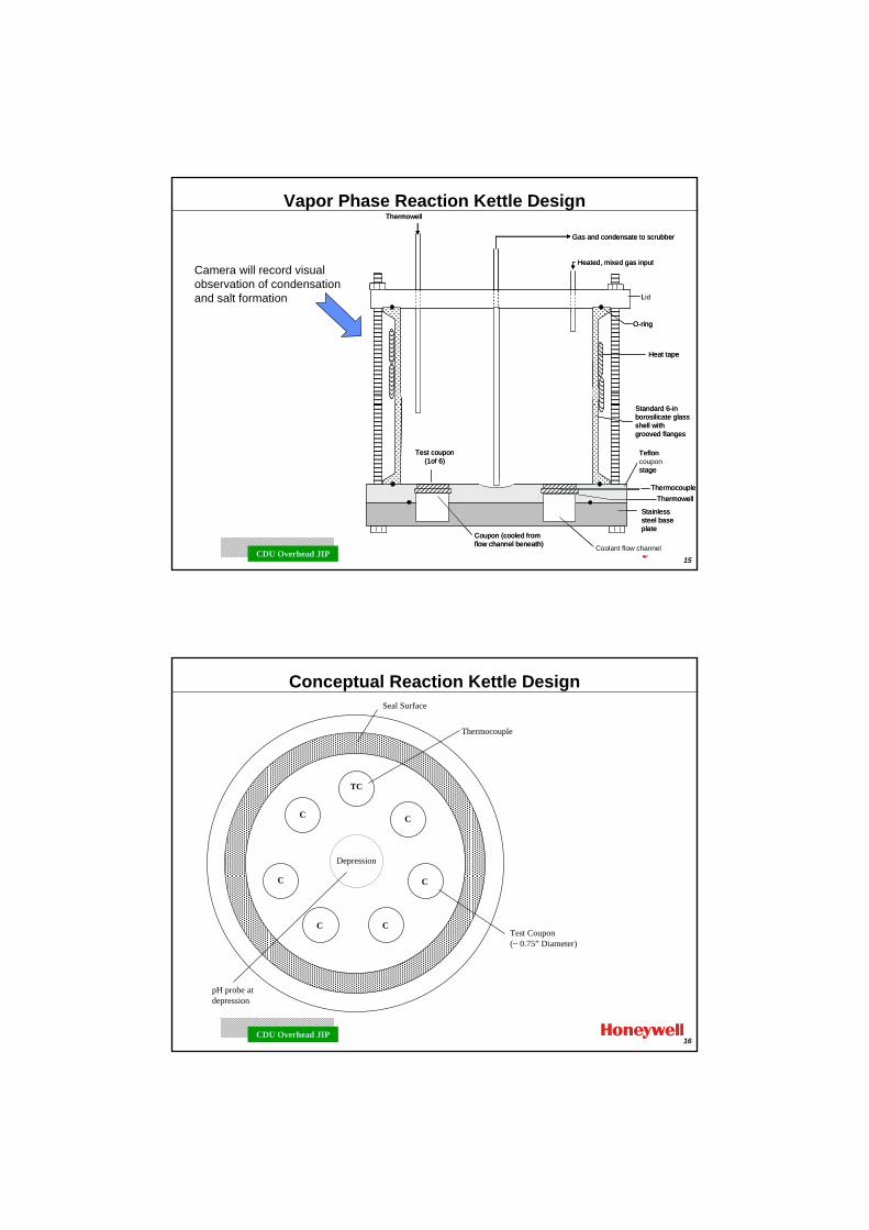
Vapor Phase Reaction Kettle Design
Camera will record visual observation of condensation and salt formation
16CDU Overhead JIP
TC
C
CC
Depression
Seal Surface
Thermocouple
C
C CTest Coupon(~ 0.75” Diameter)
pH probe at depression
Conceptual Reaction Kettle Design
17CDU Overhead JIP
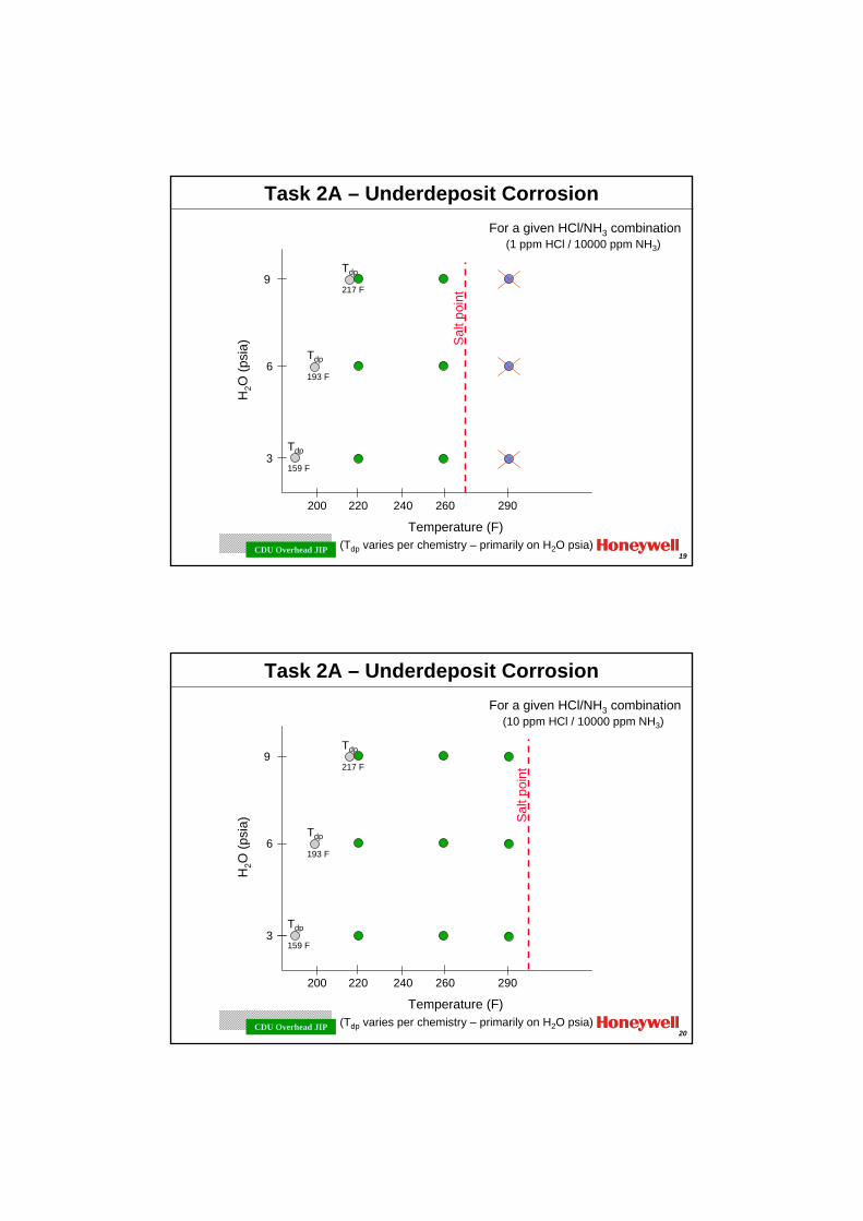
Task 2A – Underdeposit Corrosion
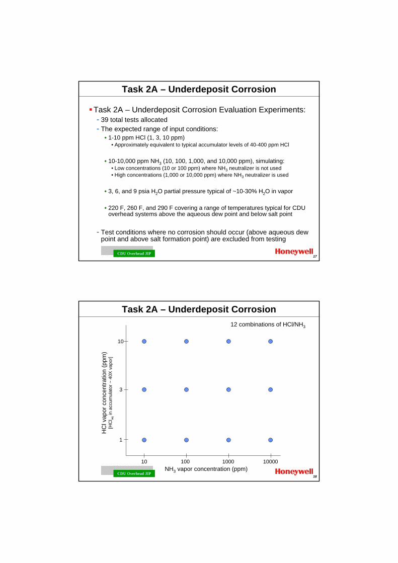
Task 2A – Underdeposit Corrosion Evaluation Experiments:- 39 total tests allocated- The expected range of input conditions:
1-10 ppm HCl (1, 3, 10 ppm) • Approximately equivalent to typical accumulator levels of 40-400 ppm HCl
10-10,000 ppm NH3 (10, 100, 1,000, and 10,000 ppm), simulating:• Low concentrations (10 or 100 ppm) where NH3 neutralizer is not used • High concentrations (1,000 or 10,000 ppm) where NH3 neutralizer is used
3, 6, and 9 psia H2O partial pressure typical of ~10-30% H2O in vapor
220 F, 260 F, and 290 F covering a range of temperatures typical for CDU overhead systems above the aqueous dew point and below salt point
- Test conditions where no corrosion should occur (above aqueous dew point and above salt formation point) are excluded from testing
18CDU Overhead JIP
Task 2A – Underdeposit Corrosion
1
3
10
HC
l vap
or c
once
ntra
tion
(ppm
)[H
Cl aq
in a
ccum
ulat
or ~
40X
vap
or]
NH3 vapor concentration (ppm)10 100 1000 10000
12 combinations of HCl/NH3
19CDU Overhead JIP
Task 2A – Underdeposit Corrosion
Tdp
217 F
3
6
9
H2O
(psi
a)
Temperature (F)
200 240
For a given HCl/NH3 combination(1 ppm HCl / 10000 ppm NH3)
(Tdp varies per chemistry – primarily on H2O psia)
290260220
Tdp
159 F
Tdp
193 F
Sal
t poi
nt
20CDU Overhead JIP
Task 2A – Underdeposit Corrosion
Tdp
217 F
3
6
9
H2O
(psi
a)
Temperature (F)
200 240
For a given HCl/NH3 combination(10 ppm HCl / 10000 ppm NH3)
(Tdp varies per chemistry – primarily on H2O psia)
290260220
Tdp
159 F
Tdp
193 F
Sal
t poi
nt
21CDU Overhead JIP
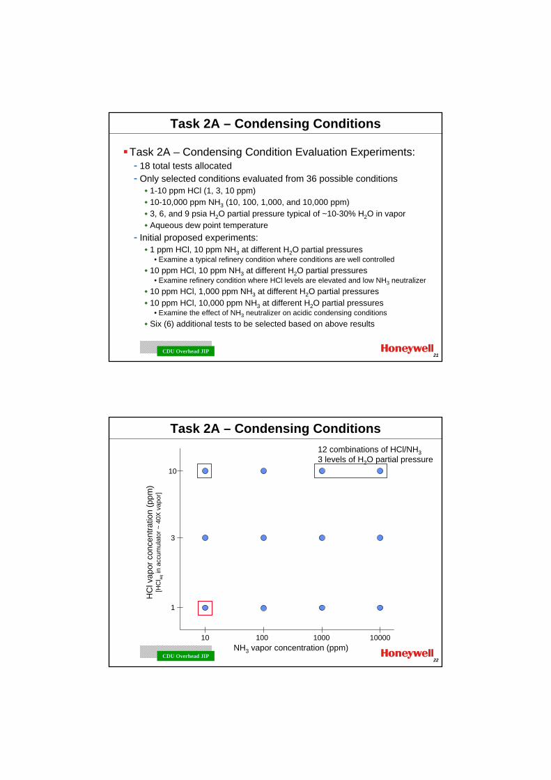
Task 2A – Condensing Conditions
Task 2A – Condensing Condition Evaluation Experiments:- 18 total tests allocated- Only selected conditions evaluated from 36 possible conditions
1-10 ppm HCl (1, 3, 10 ppm) 10-10,000 ppm NH3 (10, 100, 1,000, and 10,000 ppm)3, 6, and 9 psia H2O partial pressure typical of ~10-30% H2O in vaporAqueous dew point temperature
- Initial proposed experiments:1 ppm HCl, 10 ppm NH3 at different H2O partial pressures
• Examine a typical refinery condition where conditions are well controlled10 ppm HCl, 10 ppm NH3 at different H2O partial pressures
• Examine refinery condition where HCl levels are elevated and low NH3 neutralizer10 ppm HCl, 1,000 ppm NH3 at different H2O partial pressures10 ppm HCl, 10,000 ppm NH3 at different H2O partial pressures
• Examine the effect of NH3 neutralizer on acidic condensing conditionsSix (6) additional tests to be selected based on above results
22CDU Overhead JIP
Task 2A – Condensing Conditions
1
3
10
HC
l vap
or c
once
ntra
tion
(ppm
)[H
Cl aq
in a
ccum
ulat
or ~
40X
vap
or]
NH3 vapor concentration (ppm)10 100 1000 10000
12 combinations of HCl/NH33 levels of H2O partial pressure
23CDU Overhead JIP
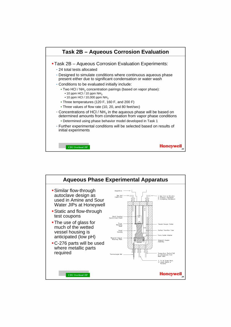
Task 2B – Aqueous Corrosion Evaluation
Task 2B – Aqueous Corrosion Evaluation Experiments:- 24 total tests allocated- Designed to simulate conditions where continuous aqueous phase
present either due to significant condensation or water wash- Conditions to be evaluated initially include:
Two HCl / NH3 concentration pairings (based on vapor phase):• 10 ppm HCl / 10 ppm NH3• 10 ppm HCl / 10,000 ppm NH3
Three temperatures (120 F, 160 F, and 200 F)Three values of flow rate (10, 20, and 80 feet/sec)
- Concentrations of HCl / NH3 in the aqueous phase will be based on determined amounts from condensation from vapor phase conditions
Determined using phase behavior model developed in Task 1- Further experimental conditions will be selected based on results of
initial experiments
24CDU Overhead JIP
Aqueous Phase Experimental Apparatus
Similar flow-through autoclave design as used in Amine and Sour Water JIPs at HoneywellStatic and flow-through test couponsThe use of glass for much of the wetted vessel housing is anticipated (low pH)C-276 parts will be used where metallic parts required
25CDU Overhead JIP
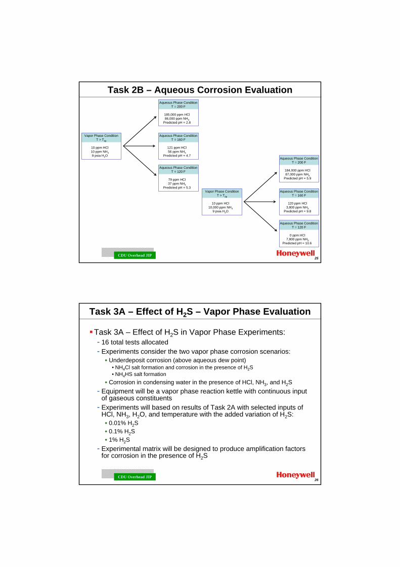
Task 2B – Aqueous Corrosion Evaluation
Vapor Phase ConditionT > Tdp
10 ppm HCl10 ppm NH39 psia H2O
Aqueous Phase ConditionT = 200 F
185,000 ppm HCl86,000 ppm NH3
Predicted pH = 2.8
Aqueous Phase ConditionT = 160 F
121 ppm HCl56 ppm NH3
Predicted pH = 4.7
Aqueous Phase ConditionT = 120 F
79 ppm HCl37 ppm NH3
Predicted pH = 5.3Vapor Phase Condition
T > Tdp
10 ppm HCl10,000 ppm NH3
9 psia H2O
Aqueous Phase ConditionT = 200 F
184,000 ppm HCl87,000 ppm NH3
Predicted pH = 5.9
Aqueous Phase ConditionT = 160 F
120 ppm HCl3,800 ppm NH3
Predicted pH = 9.8
Aqueous Phase ConditionT = 120 F
0 ppm HCl7,800 ppm NH3
Predicted pH = 10.6
26CDU Overhead JIP
Task 3A – Effect of H2S – Vapor Phase Evaluation
Task 3A – Effect of H2S in Vapor Phase Experiments:- 16 total tests allocated- Experiments consider the two vapor phase corrosion scenarios:
Underdeposit corrosion (above aqueous dew point)• NH4Cl salt formation and corrosion in the presence of H2S• NH4HS salt formation
Corrosion in condensing water in the presence of HCl, NH3, and H2S- Equipment will be a vapor phase reaction kettle with continuous input
of gaseous constituents- Experiments will based on results of Task 2A with selected inputs of
HCl, NH3, H2O, and temperature with the added variation of H2S:0.01% H2S0.1% H2S1% H2S
- Experimental matrix will be designed to produce amplification factors for corrosion in the presence of H2S
27CDU Overhead JIP
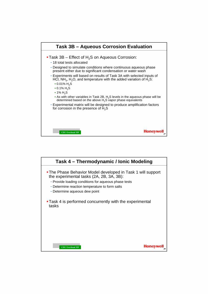
Task 3B – Aqueous Corrosion Evaluation
Task 3B – Effect of H2S on Aqueous Corrosion:- 18 total tests allocated- Designed to simulate conditions where continuous aqueous phase
present either due to significant condensation or water wash- Experiments will based on results of Task 3A with selected inputs of
HCl, NH3, H2O, and temperature with the added variation of H2S:0.01% H2S0.1% H2S1% H2SAs with other variables in Task 2B, H2S levels in the aqueous phase will be determined based on the above H2S vapor phase equivalents
- Experimental matrix will be designed to produce amplification factors for corrosion in the presence of H2S
28CDU Overhead JIP
Task 4 – Thermodynamic / Ionic Modeling
The Phase Behavior Model developed in Task 1 will support the experimental tasks (2A, 2B, 3A, 3B):- Provide loading conditions for aqueous phase tests- Determine reaction temperature to form salts- Determine aqueous dew point
Task 4 is performed concurrently with the experimental tasks
29CDU Overhead JIP
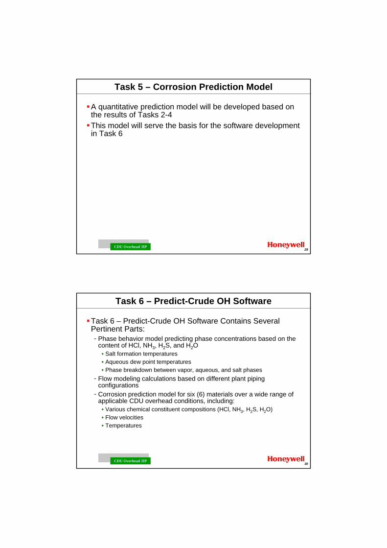
Task 5 – Corrosion Prediction Model
A quantitative prediction model will be developed based on the results of Tasks 2-4This model will serve the basis for the software development in Task 6
30CDU Overhead JIP
Task 6 – Predict-Crude OH Software
Task 6 – Predict-Crude OH Software Contains Several Pertinent Parts:- Phase behavior model predicting phase concentrations based on the
content of HCl, NH3, H2S, and H2OSalt formation temperaturesAqueous dew point temperaturesPhase breakdown between vapor, aqueous, and salt phases
- Flow modeling calculations based on different plant piping configurations
- Corrosion prediction model for six (6) materials over a wide range of applicable CDU overhead conditions, including:
Various chemical constituent compositions (HCl, NH3, H2S, H2O)Flow velocitiesTemperatures

31CDU Overhead JIP
The program is anticipated to be performed over a period of approximately 30 months from the date of start-upMinimum sponsorship for program start-up is 6 companiesFull sponsorship is 12 companies
Please contact:- Brian Chambers
[email protected] or 281-248-0705- Sridhar Srinivasan
[email protected] or 281-248-0700
Appendix 6
Corrosion failure atlas
Minutes of EFC WP15 Corrosion in the Refinery Industry 12 September 2012
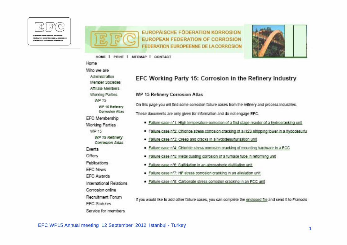
EFC WP15 Annual meeting 12 September 2012 Istanbul - Turkey 1
EFC Working Party 15 plan work 2011-2013
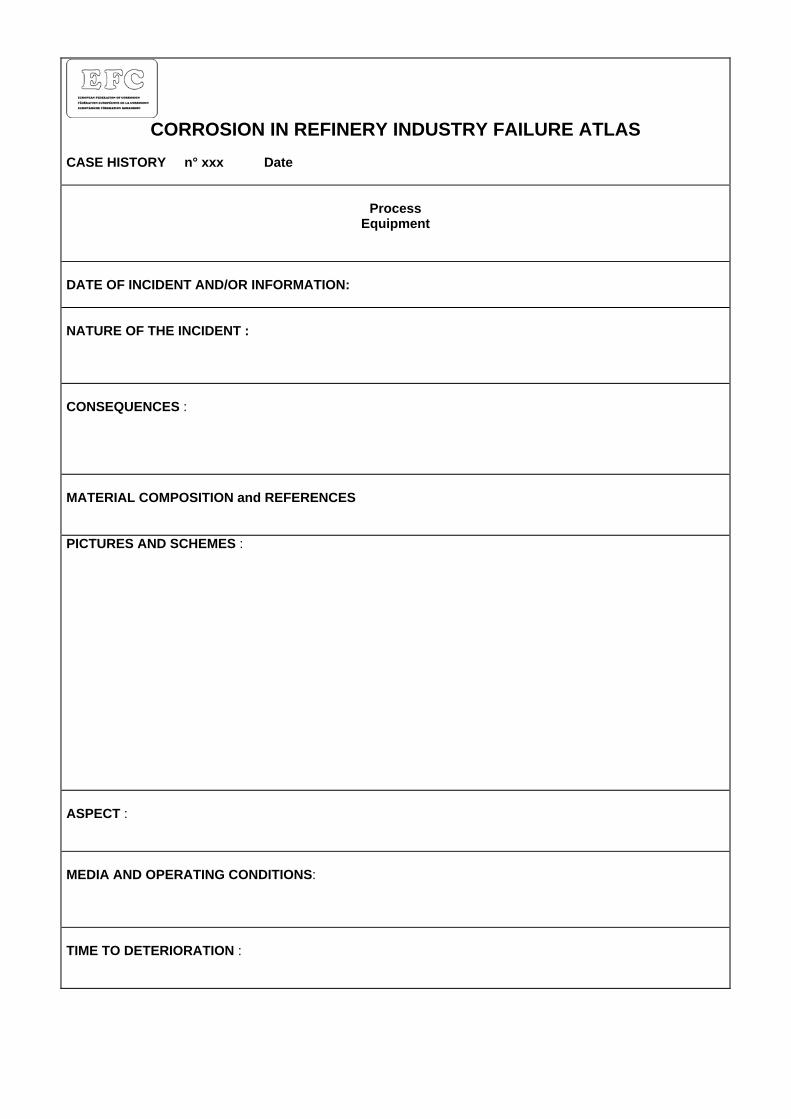
CORROSION IN REFINERY INDUSTRY FAILURE ATLAS
CASE HISTORY n° xxx Date
Process Equipment
DATE OF INCIDENT AND/OR INFORMATION: NATURE OF THE INCIDENT : CONSEQUENCES : MATERIAL COMPOSITION and REFERENCES PICTURES AND SCHEMES : ASPECT : MEDIA AND OPERATING CONDITIONS: TIME TO DETERIORATION :
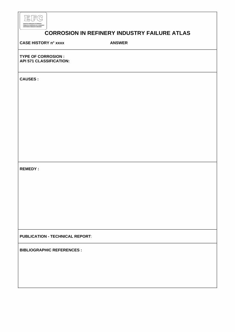
CORROSION IN REFINERY INDUSTRY FAILURE ATLAS
CASE HISTORY n° xxxx ANSWER TYPE OF CORROSION : API 571 CLASSIFICATION: CAUSES : REMEDY : PUBLICATION - TECHNICAL REPORT: BIBLIOGRAPHIC REFERENCES :
Appendix 7
ESOPE 2013 Conference
Minutes of EFC WP15 Corrosion in the Refinery Industry 12 September 2012
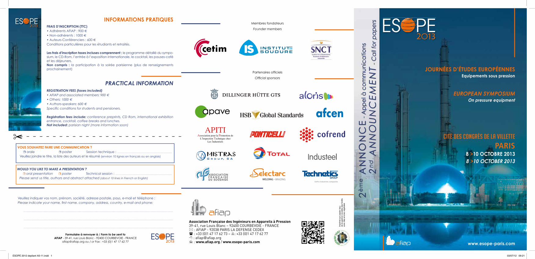
EUROPEAN SYMPOSIUMOn pressure equipment
JOURNÉES D’ÉTUDES EUROPÉENNESEquipements sous pression
CITÉ DES CONGRÈS DE LA VILLETTE
PARIS8 >10 OCTOBRE 20138 >10 OCTOBER 2013
2è
me A
NN
ON
CE
- A
pp
el à
co
mm
un
ica
tion
s
2
nd A
NN
OU
NC
EM
EN
T -
Ca
ll fo
r pa
pe
rs
www.esope-paris.com
Association Française des Ingénieurs en Appareils à Pression39-41, rue Louis Blanc – 92400 COURBEVOIE - FRANCE* : AFIAP - 92038 PARIS LA DEFENSE CEDEX( : +33 (0)1 47 17 62 73 – 7: +33 (0)1 47 17 62 778 : [email protected] : www.afiap.org / www.esope-paris.com
Imp
rimé
sur
pap
ier
issu
de
la g
estio
n d
urab
le d
es fo
rêts
avec
des
enc
res
végé
tale
s
Membres fondateurs
Partenaires officiels
Formulaire à renvoyer à / Form to be sent to AFIAP - 39-41, rue Louis Blanc - 92400 Courbevoie - FranCe
[email protected] ou / or Fax : +33 (0)1 47 17 62 77
Founder members
Official sponsors
Vous souhAItez FAIre une communIcAtIon ?r orale r poster Session technique : ..........................................................................................................................
Veuillez joindre le titre, la liste des auteurs et le résumé (environ 10 lignes en français ou en anglais)
InFormAtIons PrAtIques FrAIs D’InscrIPtIon (ttc)• Adhérents AFIAP : 900 e• �Non-adhérents : 1000 e• �Auteurs-Conférenciers : 600 eConditions particulières pour les étudiants et retraités.
Les frais d’inscription taxes incluses comprennent : le programme détaillé du sympo-sium, le CD-Rom, l’entrée à l’exposition internationale, le cocktail, les pauses-café et les déjeuners.non compris : la participation à la soirée parisienne (plus de renseignements prochainement)
Would you like to make a presentation ?r oral presentation r poster Technical session : ..............................................................................................................................
Please send us title, authors and abstract attached (about 10 lines in French or English)
practical inFormation reGistration Fees (taxes included)• AFIAP and associated members: 900 e• �Others: 1000 e• Authors-speakers: 600 eSpecific conditions for students and pensioners.
registration fees include: conference preprints, CD Rom, international exhibition entrance, cocktail, coffee breaks and lunches.not included: parisian night (more information soon)
"APITI
Association pour la Promotion deL'Inspection Technique chez
Les Industriels
G r o u p, S A
Veuillez indiquer vos nom, prénom, société, adresse postale, pays, e-mail et téléphone :Please indicate your name, first name, company, address, country, e-mail and phone:
............................................................................................................................................................................................................................................................................................................................................
............................................................................................................................................................................................................................................................................................................................................
............................................................................................................................................................................................................................................................................................................................................
ESOPE 2012 depliant A5-11.indd 1 03/07/12 09:21
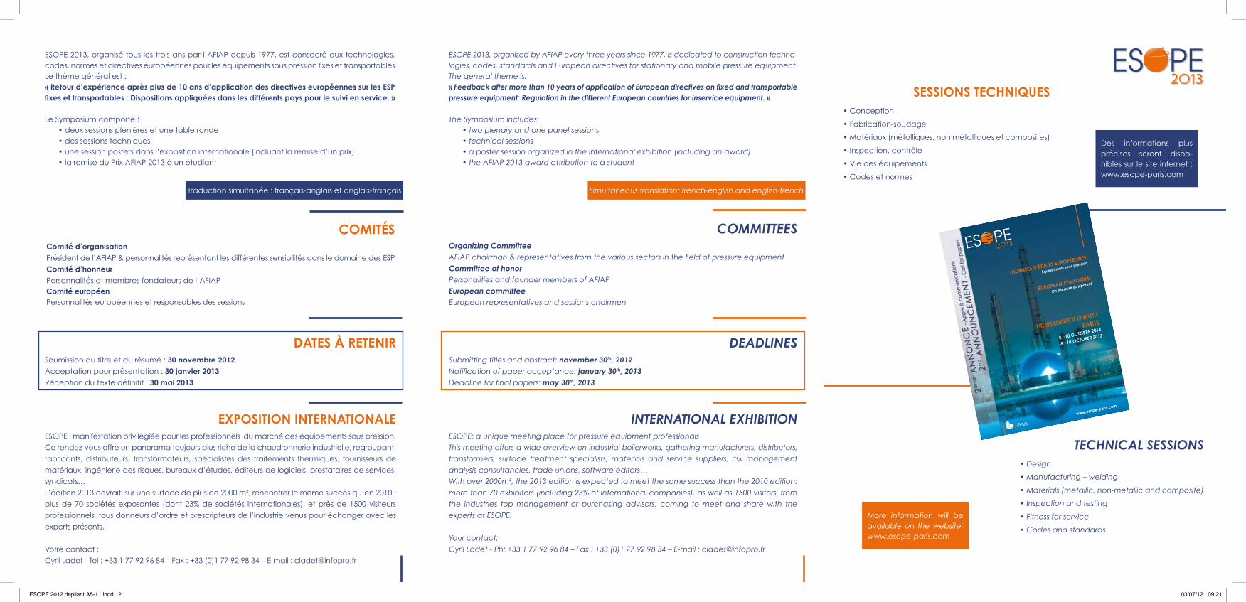
ESOPE 2013, organisé tous les trois ans par l’AFIAP depuis 1977, est consacré aux technologies, codes, normes et directives européennes pour les équipements sous pression fixes et transportablesLe thème général est :« retour d’expérience après plus de 10 ans d’application des directives européennes sur les esP fixes et transportables ; Dispositions appliquées dans les différents pays pour le suivi en service. »
Le Symposium comporte :• deux sessions plénières et une table ronde• des sessions techniques• une session posters dans l’exposition internationale (incluant la remise d’un prix)• la remise du Prix AFIAP 2013 à un étudiant
ESOPE 2013, organized by AFIAP every three years since 1977, is dedicated to construction techno-logies, codes, standards and European directives for stationary and mobile pressure equipmentThe general theme is:« Feedback after more than 10 years of application of European directives on fixed and transportable pressure equipment; regulation in the different european countries for inservice equipment. »
The Symposium includes:• two plenary and one panel sessions• technical sessions• a poster session organized in the international exhibition (including an award)• the AFIAP 2013 award attribution to a student
DAtes À retenIr Soumission du titre et du résumé : 30 novembre 2012Acceptation pour présentation : 30 janvier 2013Réception du texte définitif : 30 mai 2013
deadlines Submitting titles and abstract: november 30th, 2012Notification of paper acceptance: january 30th, 2013Deadline for final papers: may 30th, 2013
comItÉs comité d’organisationPrésident de l’AFIAP & personnalités représentant les différentes sensibilités dans le domaine des ESP
comité d’honneurPersonnalités et membres fondateurs de l’AFIAPcomité européenPersonnalités européennes et responsables des sessions
committees organizing committeeAFIAP chairman & representatives from the various sectors in the field of pressure equipment
committee of honorPersonalities and founder members of AFIAP
european committeeEuropean representatives and sessions chairmen
eXPosItIon InternAtIonALe ESOPE : manifestation privilégiée pour les professionnels du marché des équipements sous pression.
Ce rendez-vous offre un panorama toujours plus riche de la chaudronnerie industrielle, regroupant:
fabricants, distributeurs, transformateurs, spécialistes des traitements thermiques, fournisseurs de
matériaux, ingénierie des risques, bureaux d’études, éditeurs de logiciels, prestataires de services,
syndicats…
L’édition 2013 devrait, sur une surface de plus de 2000 m², rencontrer le même succès qu’en 2010 :
plus de 70 sociétés exposantes (dont 23% de sociétés internationales), et près de 1500 visiteurs
professionnels, tous donneurs d’ordre et prescripteurs de l’industrie venus pour échanger avec les
experts présents.
Votre contact :
Cyril Ladet - Tel : +33 1 77 92 96 84 – Fax : +33 (0)1 77 92 98 34 – E-mail : [email protected]
sessIons technIques • Conception
• Fabrication-soudage
• Matériaux (métalliques, non métalliques et composites)
• Inspection, contrôle
• Vie des équipements
• Codes et normes
technical sessions • Design
• Manufacturing – welding
• Materials (metallic, non-metallic and composite)
• Inspection and testing
• Fitness for service
• Codes and standards
international eXhiBition ESOPE: a unique meeting place for pressure equipment professionals
This meeting offers a wide overview on industrial boilerworks, gathering manufacturers, distributors,
transformers, surface treatment specialists, materials and service suppliers, risk management
analysis consultancies, trade unions, software editors…
With over 2000m², the 2013 edition is expected to meet the same success than the 2010 edition:
more than 70 exhibitors (including 23% of international companies), as well as 1500 visitors, from
the industries top management or purchasing advisors, coming to meet and share with the
experts at ESOPE.
Your contact:
Cyril Ladet - Ph: +33 1 77 92 96 84 – Fax : +33 (0)1 77 92 98 34 – E-mail : [email protected]
Traduction simultanée : français-anglais et anglais-français Simultaneous translation: french-english and english-french
EUROPEAN SYMPOSIUM
On pressure equipment
JOURNÉES D’ÉTUDES EUROPÉENNES
Equipements sous pression
CITÉ DES CONGRÈS DE LA VILLETTE
PARIS
8 >10 OCTOBRE 2013
8 >10 OCTOBER 2013
2èm
e A
NN
ON
CE
- A
pp
el à
co
mm
un
ica
tion
s
2n
d A
NN
OU
NC
EM
EN
T -
Ca
ll fo
r pa
pe
rs
www.esope-paris.com
Des informations plus précises seront dispo-nibles sur le site internet : www.esope-paris.com
More information will be available on the website: www.esope-paris.com
ESOPE 2012 depliant A5-11.indd 2 03/07/12 09:21