Embed Size (px)
Citation preview
Antenna Analyzer
By:
Mike Shelby – W7RIS
January 2015
Overview
• Different types of Antenna Analyzers
• Not much content on theory
• How to troubleshoot antenna system problems
• How to maximize your antenna system performance
• Useful things you can do with an analyzer
Antenna Analyzers • Some hams don’t care about the SWR.
– A good Antenna Tuner can fix any SWR problem.
• Some hams only want to know if they have a good SWR.
– A simple Antenna Analyzer is all that’s needed
• Other hams want to know how to maximize their antenna system performance.
– You probably want an Antenna Analyzer with more advanced features
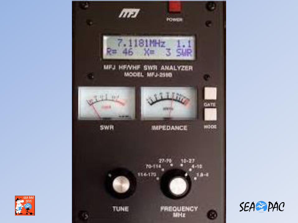
Antenna Analyzer
• The #1 tool for a Ham
• All Antenna Analyzers will display SWR
• Most will display the Impedance
• Some analyzers will display the complex products that make up the Impedance.
• Some analyzers have advanced functions to diagnose Antenna System Problems
Antenna Analyzers
• The introduction of the MFJ low cost Antenna Analyzer has enabled hams to experiment with antenna designs.
• This device was a very significant contribution to the ham community.
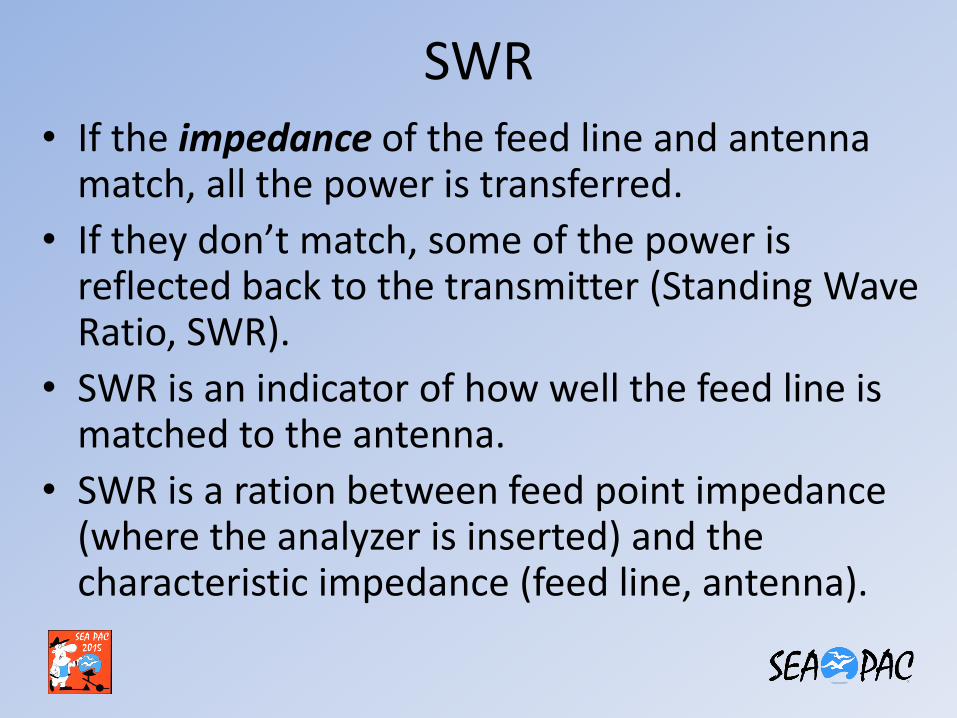
SWR • If the impedance of the feed line and antenna
match, all the power is transferred.
• If they don’t match, some of the power is reflected back to the transmitter (Standing Wave Ratio, SWR).
• SWR is an indicator of how well the feed line is matched to the antenna.
• SWR is a ration between feed point impedance (where the analyzer is inserted) and the characteristic impedance (feed line, antenna).
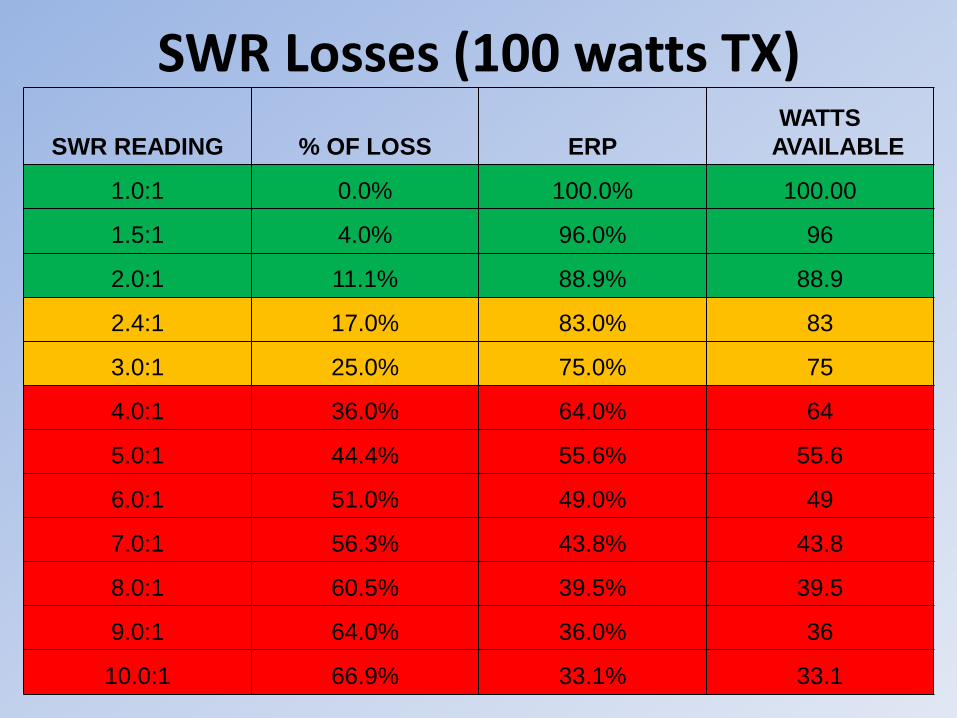
SWR Losses (100 watts TX)
SWR READING % OF LOSS ERP
WATTS
AVAILABLE
1.0:1 0.0% 100.0% 100.00
1.5:1 4.0% 96.0% 96
2.0:1 11.1% 88.9% 88.9
2.4:1 17.0% 83.0% 83
3.0:1 25.0% 75.0% 75
4.0:1 36.0% 64.0% 64
5.0:1 44.4% 55.6% 55.6
6.0:1 51.0% 49.0% 49
7.0:1 56.3% 43.8% 43.8
8.0:1 60.5% 39.5% 39.5
9.0:1 64.0% 36.0% 36
10.0:1 66.9% 33.1% 33.1
SWR
• Point 1: Most amateur transmitters are designed to operate / tolerate a 2:1 SWR or lower.
• Point 2: An antenna Tuner fools a transmitter, making it think it’s transmitting into a 50 ohm load. You still have the SWR losses in the feed line and antenna system.
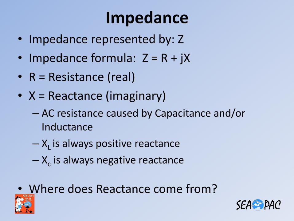
Impedance • Impedance represented by: Z
• Impedance formula: Z = R + jX
• R = Resistance (real)
• X = Reactance (imaginary)
– AC resistance caused by Capacitance and/or Inductance
– XL is always positive reactance
– Xc is always negative reactance
• Where does Reactance come from?
Reactance
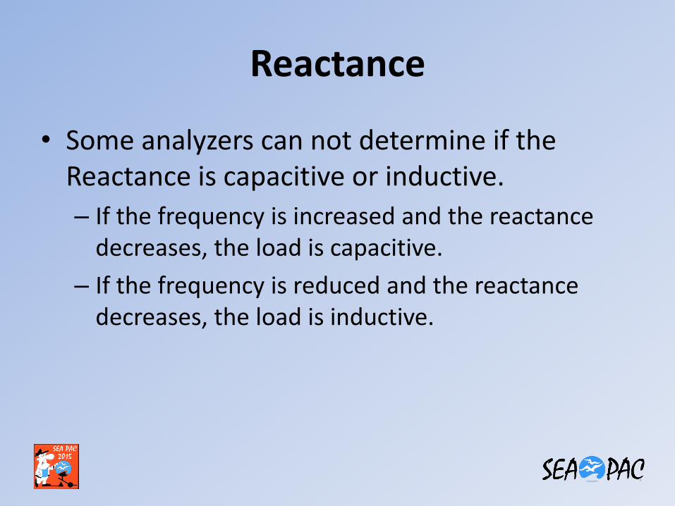
• Some analyzers can not determine if the Reactance is capacitive or inductive.
– If the frequency is increased and the reactance decreases, the load is capacitive.
– If the frequency is reduced and the reactance decreases, the load is inductive.
Reactance
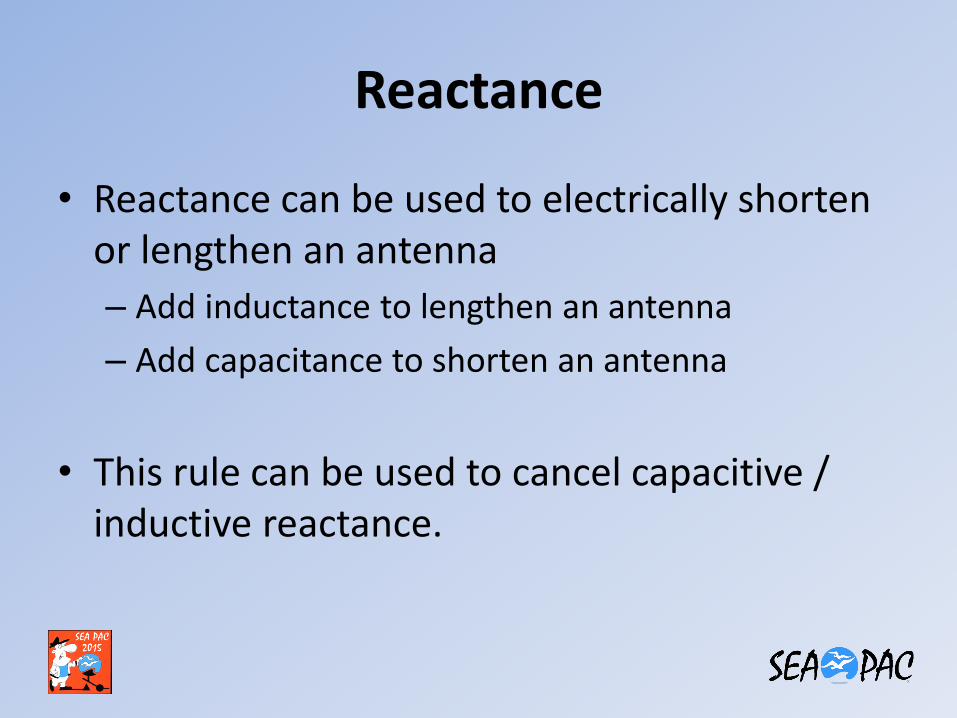
• Reactance can be used to electrically shorten or lengthen an antenna
– Add inductance to lengthen an antenna
– Add capacitance to shorten an antenna
• This rule can be used to cancel capacitive / inductive reactance.
When is an Antenna in Resonance?
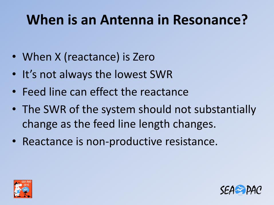
• When X (reactance) is Zero
• It’s not always the lowest SWR
• Feed line can effect the reactance
• The SWR of the system should not substantially change as the feed line length changes.
• Reactance is non-productive resistance.
Reactance
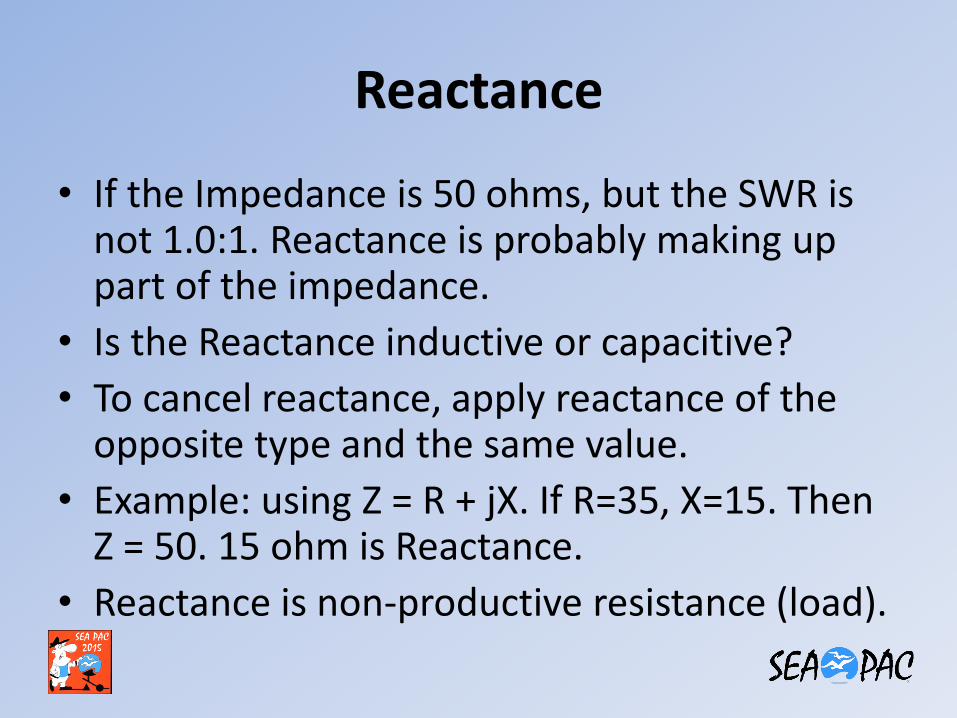
• If the Impedance is 50 ohms, but the SWR is not 1.0:1. Reactance is probably making up part of the impedance.
• Is the Reactance inductive or capacitive?
• To cancel reactance, apply reactance of the opposite type and the same value.
• Example: using Z = R + jX. If R=35, X=15. Then Z = 50. 15 ohm is Reactance.
• Reactance is non-productive resistance (load).
Tuning your Antenna Dipoles
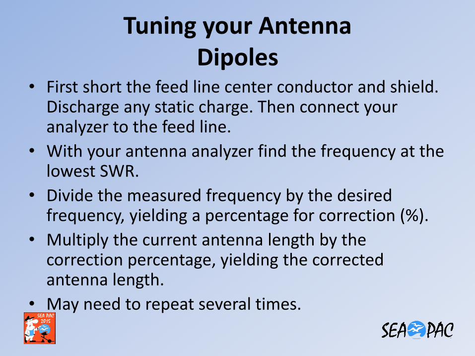
• First short the feed line center conductor and shield. Discharge any static charge. Then connect your analyzer to the feed line.
• With your antenna analyzer find the frequency at the lowest SWR.
• Divide the measured frequency by the desired frequency, yielding a percentage for correction (%).
• Multiply the current antenna length by the correction percentage, yielding the corrected antenna length.
• May need to repeat several times.
Problems at Low Freq
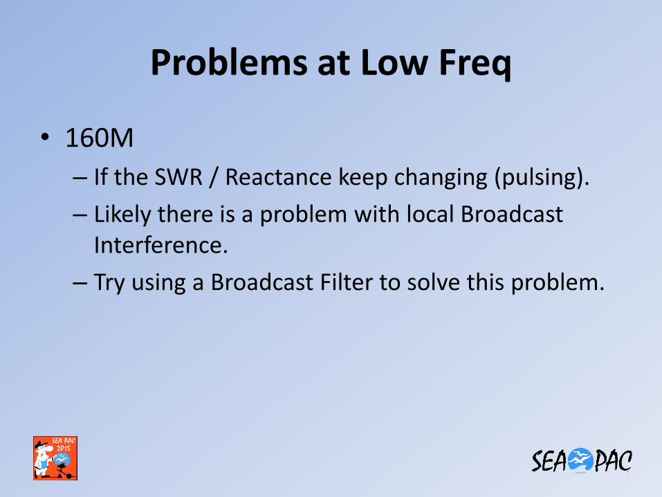
• 160M
– If the SWR / Reactance keep changing (pulsing).
– Likely there is a problem with local Broadcast Interference.
– Try using a Broadcast Filter to solve this problem.
Tuning your Tuner
• This process is intended for a Manual Antenna Tuner, not an Auto Tuner.
• Connect your Analyzer to the TX of the tuner.
• Set the frequency of the Analyzer.
• Adjust the tuner until the SWR read unity (1:1).
• Write the frequency and tuner setting down in a note book or spreadsheet.
How to test a Dummy Load • A Dummy Load will show zero reactance and a
50 ohm resistive load over the specified band width.
• SWR of 1.0:1
• Use a very short piece of coax between analyzer and Dummy Load
• Anything other then a small amount of SWR variation indicated a bad Dummy Load.
• This procedure help to validate proper analyzer operation.
Simple Coax Test • Connect a 50 ohm load at the far end of the
coax.
• 50 ohm load: 50 ohm resistor (not wire wound) or 50 ohm dummy load.
• Sweep the coax with your antenna analyzer.
• The SWR should be very close to 1:1 for the entire usable frequency.
• This only shows the impedance is 50 ohms .
• There maybe other coax losses or problems not being shown.
SWR changes with coax length • If the SWR changes with coax line length, line
placement, or grounding.
– Coax is probably carrying common mode current and radiating.
– Coax is not 50 ohm.
– Coax has significant loss.
• Start by first testing the SWR using a very short piece of coax at the antenna feed point.
• Then add your long piece of coax. Make sure the SWR does not substantially change.
How to test a Balun • If you purchase a balun at a swap meet or if you
build your own balun’s, how do you know if it is working correctly?
• For a 1:1 balun use a 50 ohm resistor across the output of the balun.
• For a 4:1 balun use a 200 ohm resistor across the output of the balun.
• The SWR should be very low over the entire frequency range of the balun.
• No reactance.
• If the SWR is not flat across the entire frequency range. The balun is questionable.
Coax Loss
• Usually under Advanced settings.
• Can be used to test losses in coax and baluns.
• Do not terminate the far end.
• Configure the analyzer for Coax Loss.
• The display will show the loss in dB at a given frequency.
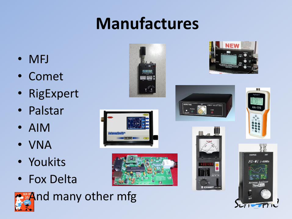
Manufactures
• MFJ
• Comet
• RigExpert
• Palstar
• AIM
• VNA
• Youkits
• Fox Delta
• And many other mfg
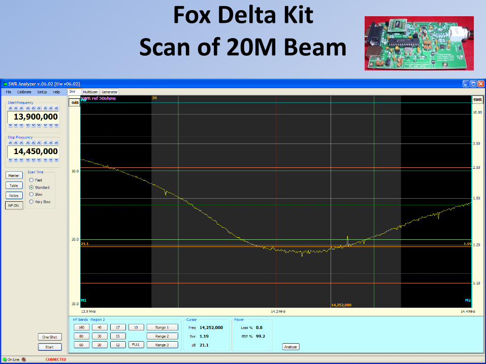
Fox Delta Kit Scan of 20M Beam
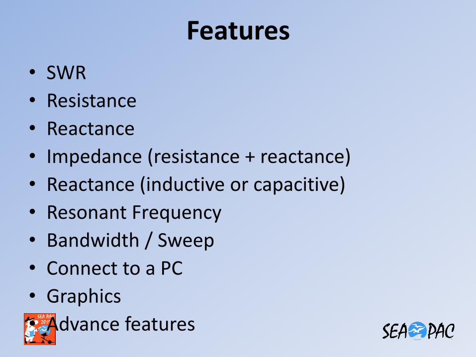
Features
• SWR
• Resistance
• Reactance
• Impedance (resistance + reactance)
• Reactance (inductive or capacitive)
• Resonant Frequency
• Bandwidth / Sweep
• Connect to a PC
• Graphics
• Advance features
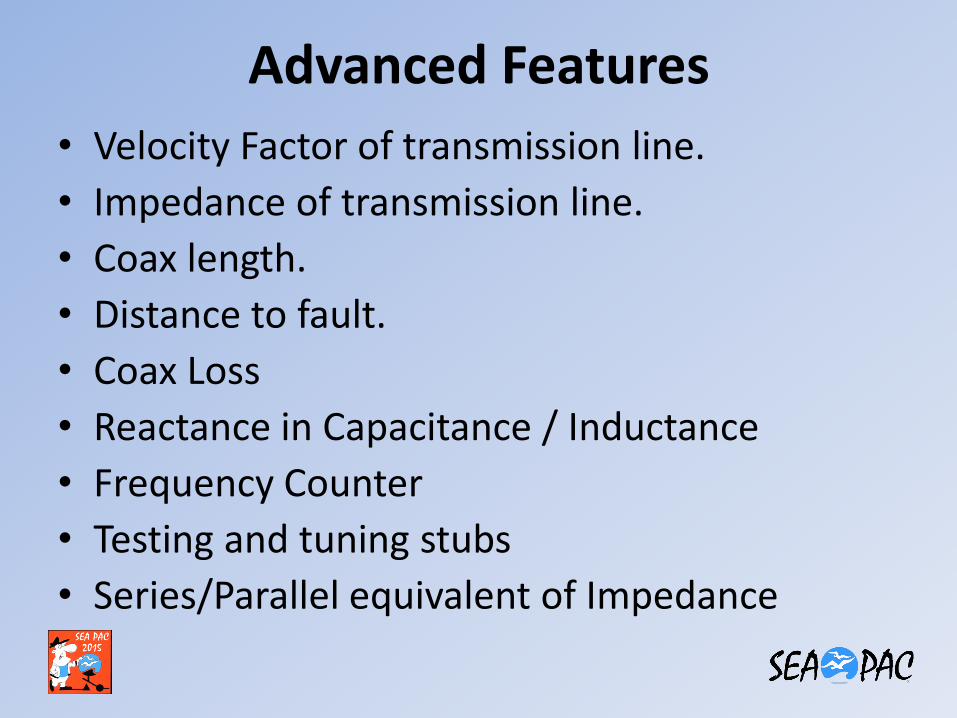
Advanced Features
• Velocity Factor of transmission line.
• Impedance of transmission line.
• Coax length.
• Distance to fault.
• Coax Loss
• Reactance in Capacitance / Inductance
• Frequency Counter
• Testing and tuning stubs
• Series/Parallel equivalent of Impedance
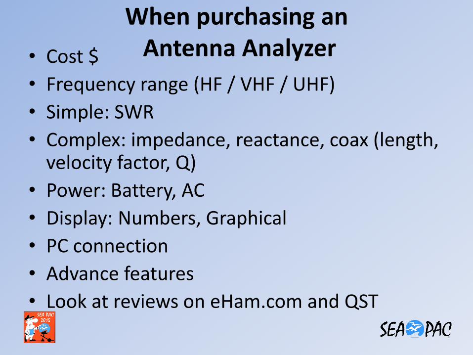
When purchasing an Antenna Analyzer • Cost $
• Frequency range (HF / VHF / UHF)
• Simple: SWR
• Complex: impedance, reactance, coax (length, velocity factor, Q)
• Power: Battery, AC
• Display: Numbers, Graphical
• PC connection
• Advance features
• Look at reviews on eHam.com and QST
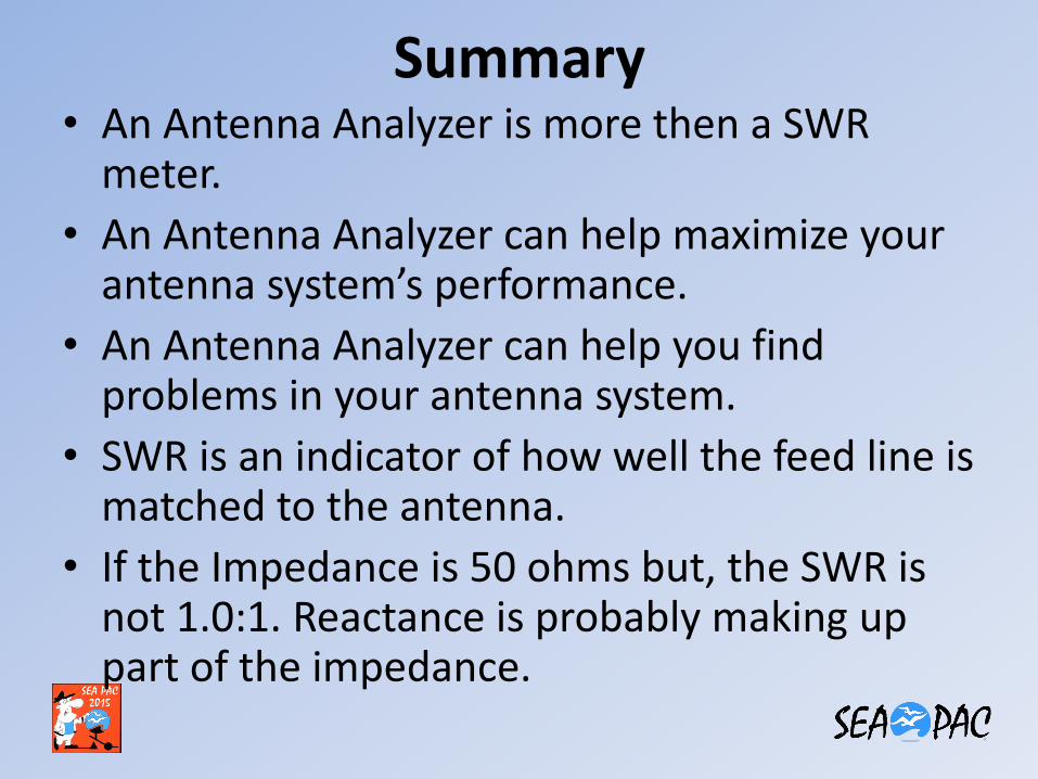
Summary • An Antenna Analyzer is more then a SWR
meter.
• An Antenna Analyzer can help maximize your antenna system’s performance.
• An Antenna Analyzer can help you find problems in your antenna system.
• SWR is an indicator of how well the feed line is matched to the antenna.
• If the Impedance is 50 ohms but, the SWR is not 1.0:1. Reactance is probably making up part of the impedance.
Summary
• Before connecting coax to your analyzer, first short the center pin to the shield. Discharge any static charge.
• First read the SWR at the antenna feed point.
• Second, if the SWR changed with the coax length or placement. There is a problem with the coax impedance, common mode current, or local RFI.
• Try to keep your SWR to 2.0:1 or less.
• RTFM. Read the manual.
• Take detailed notes and keep them in a safe place.

End of program
• Any questions ???