Embed Size (px)
Citation preview
TAS-I BUTL
27/05/2010 All rights reserved, 2010, Thales Alenia Space
Template reference : 100181670S
-EN
ANTARES Project: Visibility AnalysisPaolo Conforto
Iris Information EventPrague, 26-27 May, 2010
All rights reserved, 2010, Thales Alenia Space
TAS-I BUTL
27/05/2010
Page 2
Contents
Visibility analysis objectives
Analysis model description
Visibility analyses results
Inputs from aviation
Conclusions and way forward
All rights reserved, 2010, Thales Alenia Space
TAS-I BUTL
27/05/2010
Page 3
Visibility Analysis Objectives
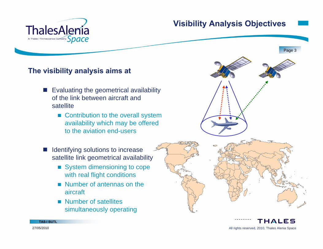
The visibility analysis aims at
Evaluating the geometrical availability of the link between aircraft and satellite Contribution to the overall system
availability which may be offered to the aviation end-users
Identifying solutions to increase satellite link geometrical availability System dimensioning to cope
with real flight conditions Number of antennas on the
aircraft Number of satellites
simultaneously operating
Egypt: 76
1
598
5567
830221
40
115
7
490
NorthAmerica3
Brazil791
Azerbaijan7China
29
India49
Australia92
All rights reserved, 2010, Thales Alenia Space
TAS-I BUTL
27/05/2010
Page 4
Simulation Model
Main elements of the simulation model Geostationary satellite
Its position on the orbital arc can be varied for analysis purpose More than one satellite can be considered for diversity purposes
Aircrafts Suitable typologies may be selected from a list of possible models Position of the satellite terminal antenna can be selected
Flight trajectories Instrument flight rules (IFR)-based trajectories imported Special trajectories generated
Satellite link between aircraft and satellite
All rights reserved, 2010, Thales Alenia Space
TAS-I BUTL
27/05/2010
Page 5
Aircraft Models
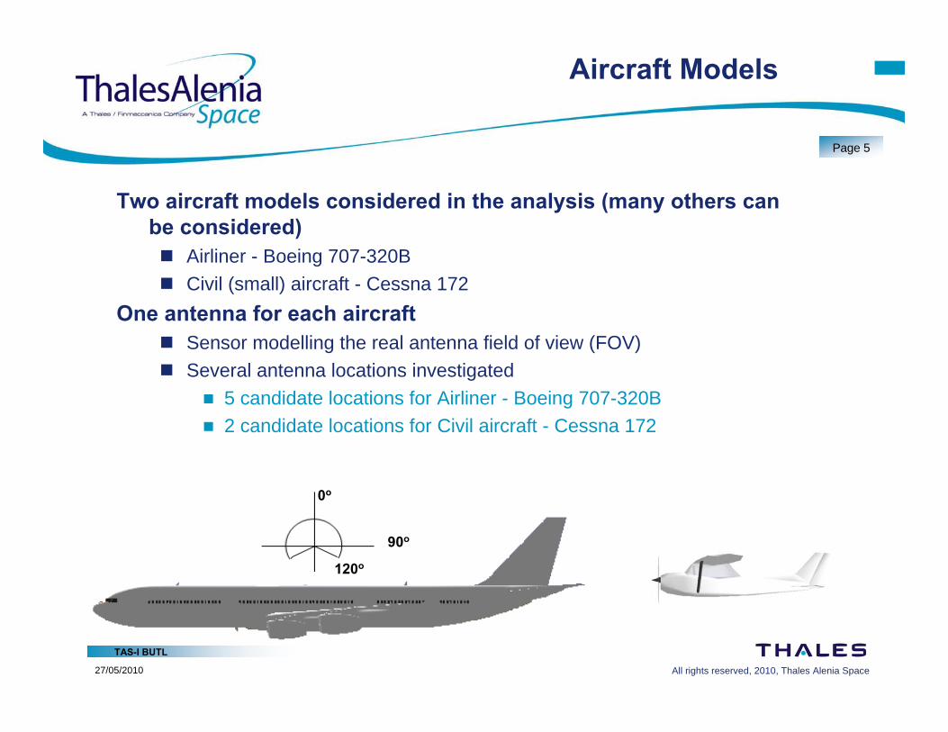
Two aircraft models considered in the analysis (many others can be considered) Airliner - Boeing 707-320B Civil (small) aircraft - Cessna 172
One antenna for each aircraft Sensor modelling the real antenna field of view (FOV) Several antenna locations investigated
5 candidate locations for Airliner - Boeing 707-320B 2 candidate locations for Civil aircraft - Cessna 172
120o
0o
90o
All rights reserved, 2010, Thales Alenia Space
TAS-I BUTL
27/05/2010
Page 6
Visibility Analysis Outputs
Several types of geometrical parameters investigated Visibility and outage events on the satellite link
Aircraft antenna field of view obstruction caused by the aircraft body (tail, wing and nose)
• Link visibility time duration and percentage• Link outage time duration and percentage• Maximum link outage time duration
Aircraft antenna-to-satellite elevation angles occurrences statistics Aircrafts flight trajectories bank and pitch angles occurrences statistics
The above results may be provided in two major scenarios based on One geostationary satellite Two geostationary satellites operating in spatial diversity
All rights reserved, 2010, Thales Alenia Space
TAS-I BUTL
27/05/2010
Page 7
Flight Trajectories
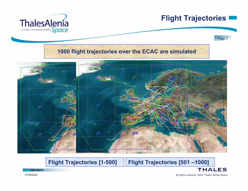
1000 flight trajectories over the ECAC are simulated
Flight Trajectories [1-500] Flight Trajectories [501 –1000]
All rights reserved, 2010, Thales Alenia Space
TAS-I BUTL
27/05/2010
Page 8
Airliner Link Outage Statistics
Antenna positions
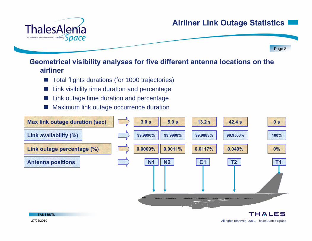
Geometrical visibility analyses for five different antenna locations on the airliner Total flights durations (for 1000 trajectories) Link visibility time duration and percentage Link outage time duration and percentage Maximum link outage occurrence duration
Link outage percentage (%)
Max link outage duration (sec)
N1 N2 C1 T2 T1
0.0009% 0.0011% 0.0117% 0.049% 0%
3.0 s 5.0 s 13.2 s 42.4 s 0 s
Link availability (%) 99.9990% 99.9998% 99.9883% 99.9503% 100%
All rights reserved, 2010, Thales Alenia Space
TAS-I BUTL
27/05/2010
Page 9
Small Aircraft Link Outage Statistics
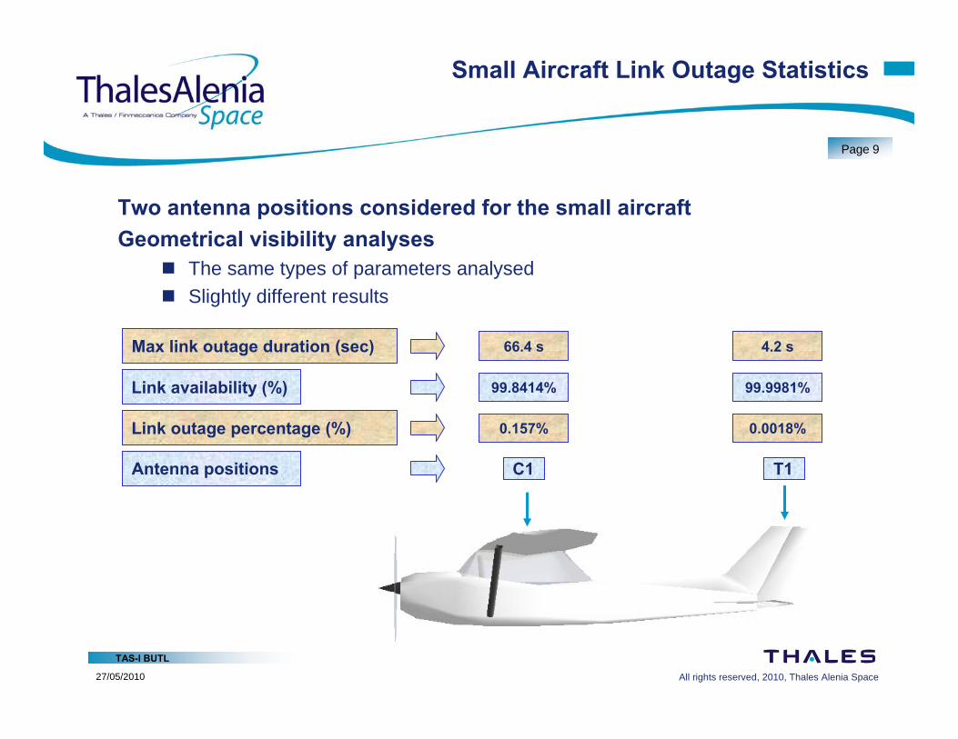
Two antenna positions considered for the small aircraftGeometrical visibility analyses
The same types of parameters analysed Slightly different results
Antenna positions
Link outage percentage (%)
Max link outage duration (sec)
C1 T1
0.157% 0.0018%
66.4 s 4.2 s
Link availability (%) 99.8414% 99.9981%
All rights reserved, 2010, Thales Alenia Space
TAS-I BUTL
27/05/2010
Page 10
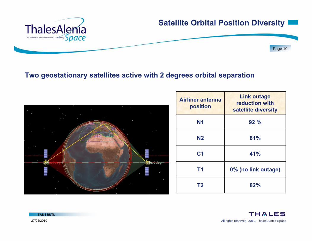
Satellite Orbital Position Diversity
Two geostationary satellites active with 2 degrees orbital separation
82%T2
0% (no link outage)T1
41%C1
81%N2
92 %N1
Link outage reduction with
satellite diversity
Airliner antenna position
All rights reserved, 2010, Thales Alenia Space
TAS-I BUTL
27/05/2010
Page 11
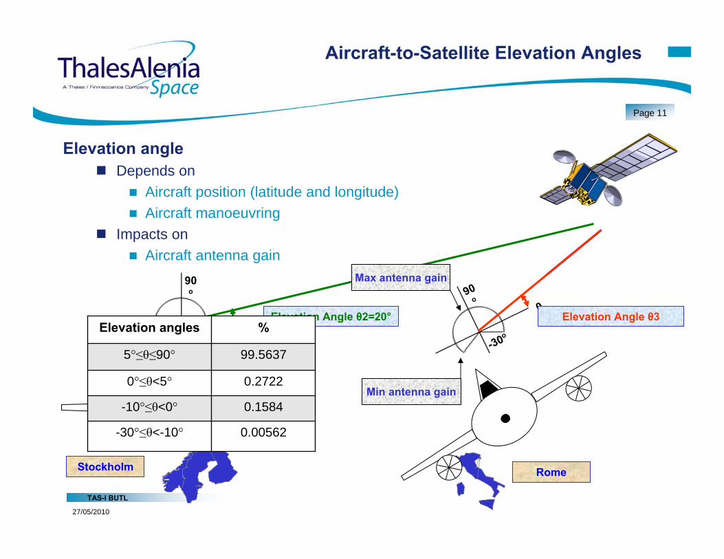
Aircraft-to-Satellite Elevation Angles
Elevation angle Depends on
Aircraft position (latitude and longitude) Aircraft manoeuvring
Impacts on Aircraft antenna gain
-30o0o
90o
Rome
Elevation Angle θ1=40°
-30o0o
90o
Stockholm
Elevation Angle θ2=20°
0.00562-30°≤θ<-10°
0.1584-10°≤θ<0°
0.27220°≤θ<5°
99.56375°≤θ≤90°
%Elevation angles-30o
0o
90o
Rome
Elevation Angle θ3
Min antenna gain
Max antenna gain
All rights reserved, 2010, Thales Alenia Space
TAS-I BUTL
27/05/2010
Page 12
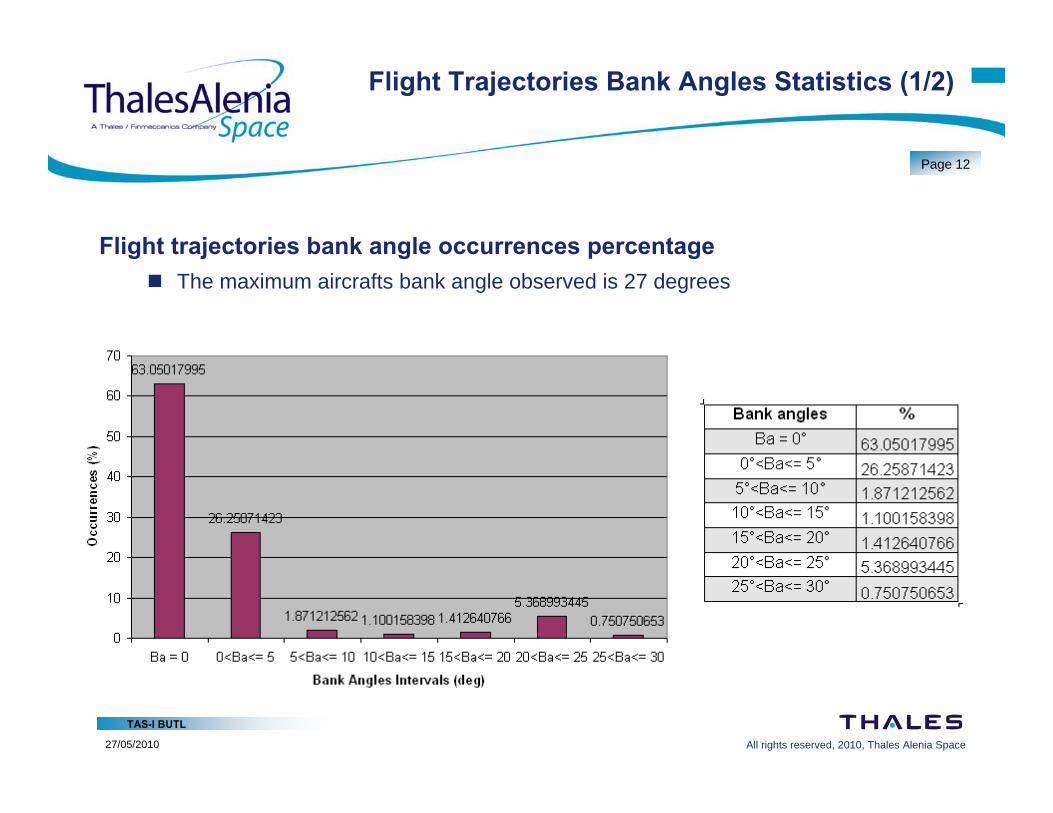
Flight Trajectories Bank Angles Statistics (1/2)
Flight trajectories bank angle occurrences percentage The maximum aircrafts bank angle observed is 27 degrees
All rights reserved, 2010, Thales Alenia Space
TAS-I BUTL
27/05/2010
Page 13
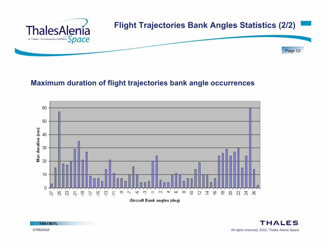
Flight Trajectories Bank Angles Statistics (2/2)
Maximum duration of flight trajectories bank angle occurrences
All rights reserved, 2010, Thales Alenia Space
TAS-I BUTL
27/05/2010
Page 14
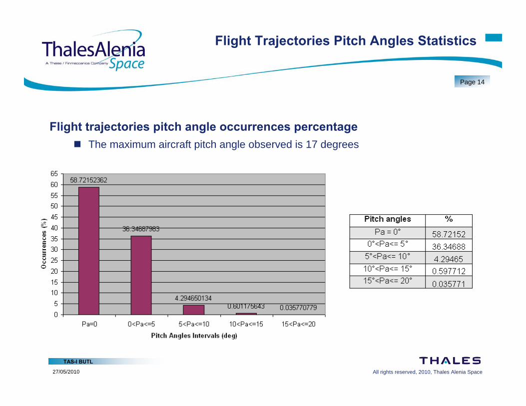
Flight Trajectories Pitch Angles Statistics
Flight trajectories pitch angle occurrences percentage The maximum aircraft pitch angle observed is 17 degrees
All rights reserved, 2010, Thales Alenia Space
TAS-I BUTL
27/05/2010
Page 15
Conclusions and Way Forward
The visibility analysis results have shown that A high level of geometrical link availability can be achieved by suitably installing the
aircraft antenna The geometrical link availability can be further increased with satellite diversity Elevation angles statistics can allow to infer good performance for the aircraft antenna
Inputs from aviation may Allow a refinement of the visibility analysis model Concern possible constraints or preferences on antenna installation on the aircrafts,
e.g. Recommended positions Allowed and not allowed positions Maximum number of antennas
Model extension to consider “Focused” study cases for statistical analysis of special flight trajectories Different aircraft models