Embed Size (px)
Citation preview
Living Planet Symposium29 June 2010 2/26/2010, Thales Alenia Space
Te
mplate
refe
rence
: 1001
816
70S
-EN
All rights reserved,
The In-flight Calibration of the GOCE Gradiometer
Stefano Cesare(1), Giuseppe Catastini(1), Rune Floberghagen(2), Daniel Lamarre(2) (1) Thales Alenia Space Italia, (2) ESA - ESTEC
ESA Living Planet Symposium
28 June - 2 July 2010, Bergen, Norway
All rights reserved 2/2010, Thales Alenia Space
Living Planet Symposium29 June 2010
2
Objectives of the Gradiometer in-flight calibration
Principle of the Gradiometer calibration method defined by Thales Alenia Space Italia (TAS-I)
Results of the Gradiometer in-flight calibration
Impacts of the calibration on the gradiometric performance
Contents

All rights reserved 2/2010, Thales Alenia Space
Living Planet Symposium29 June 2010
3
In-Flight Calibration Objectives
In synthesis, the objective of the in-flight calibration is to turn the real Gradiometer into an ideal Gradiometer (in the data post processing).
In an ideal Gradiometer all accelerometers are identical (with unitary scale factors), linear and perfectly aligned to the Gradiometer reference frame.
The GGT diagonal components are obtained from the differential accelerations:
and are affected only by the accelerometer measurement noise.
In-line Ultra-Sensitive (US) axis
Transversal Ultra-Sensitive axis
Less-Sensitive (LS) axis
GGT = Gravity Gradient Tensor

All rights reserved 2/2010, Thales Alenia Space
Living Planet Symposium29 June 2010
4
In-Flight Calibration Objectives
L
ac,x
x1 x2
a1 = K1ac,x a2 = K2ac,x
z1 z2
In a real Gradiometer the accelerometers have different scale factors, non-linear response, their sensitive axes are non-orthogonal and misaligned. These “defects” couple with the residual linear and angular accelerations of the satellite and give rise to spurious differential accelerations errors on the GGT.
Differential scale factor coupling with in-line linear acceleration
Misalignment coupling with transversal linear acceleration
Acceleration measured by the accelerometer Ai of a real Gradiometer:
[K]i = scale factor matrix
[dR]i = rotation matrix from accelerometer frame to Gradiometer frame
[dS]i = accelerometer inter-axis coupling matrix ; [K2] = quadratic factor matrix

All rights reserved 2/2010, Thales Alenia Space
Living Planet Symposium29 June 2010
5
In-Flight Calibration Objectives
)(2
1
)(2
1
,
,
jiijd
jiijc
aaa
aaa
Scale factors, sensitive axis misalignments and non-orthogonality are collected in three 6x6 Calibration Matrices Mij (one for each Gradiometer arm). To recover the accelerations experienced by the proof masses along the Gradiometer axes from the measured ones, the Inverse Calibration Matrices MIij must be known.
(ij = 14, 25, 36)
Gradiometer in-flight calibration objectives: Measure and correct the accelerometer quadratic factors (non linearity). Measure the elements of the Inverse Calibration Matrices.
)(2
1
)(2
1
,
,
jiijd
jiijc
aaa
aaa
ai = acceleration measured by the real accelerometer Ai on its reference frame
ai = acceleration measured by an ideal accelerometer with unitary scale factor and perfectly aligned to the Gradiometer frame
All rights reserved 2/2010, Thales Alenia Space
Living Planet Symposium29 June 2010
6
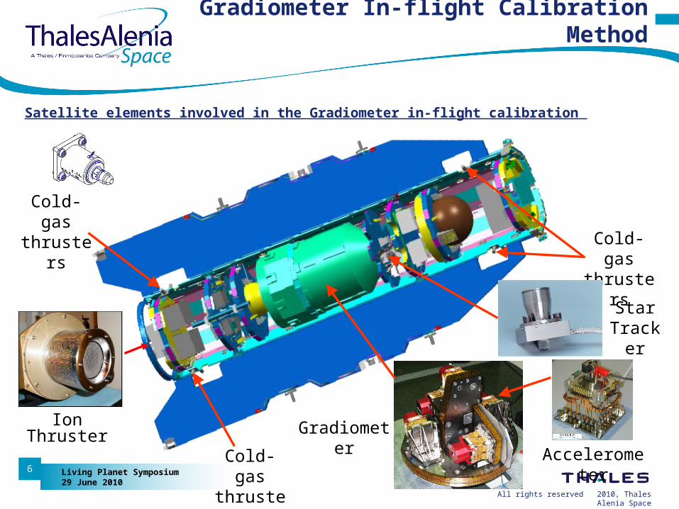
Satellite elements involved in the Gradiometer in-flight calibration
Gradiometer In-flight Calibration Method
Cold-gas thrusters
Gradiometer
Star Tracker
Ion Thruster
AccelerometerCold-gas thrusters
Cold-gas thrusters
All rights reserved 2/2010, Thales Alenia Space
Living Planet Symposium29 June 2010
7
Quadratic Factor Calibration Method
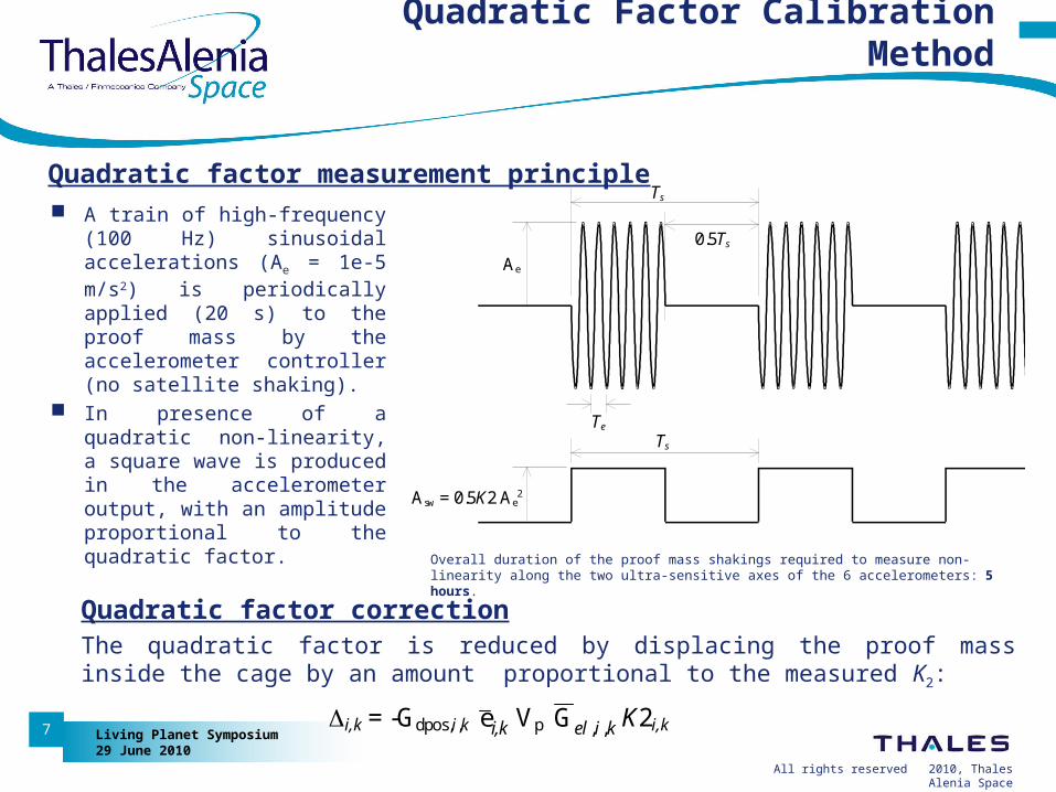
Quadratic factor measurement principle
A train of high-frequency (100 Hz) sinusoidal accelerations (Ae = 1e-5 m/s2) is periodically applied (20 s) to the proof mass by the accelerometer controller (no satellite shaking).
In presence of a quadratic non-linearity, a square wave is produced in the accelerometer output, with an amplitude proportional to the quadratic factor.
Ts
TeTs
Ae
Asw = 0.5K2 Ae2
INPUT
OUTPUT
0.5Ts
Quadratic factor correctionThe quadratic factor is reduced by displacing the proof mass inside the cage by an amount proportional to the measured K2:
i,k = -Gdpos,i,k i,ke Vp kiel ,,G K2i,k
Overall duration of the proof mass shakings required to measure non-linearity along the two ultra-sensitive axes of the 6 accelerometers: 5 hours.
All rights reserved 2/2010, Thales Alenia Space
Living Planet Symposium29 June 2010
8
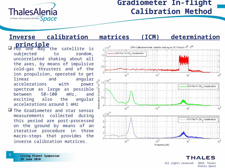
Inverse calibration matrices (ICM) determination principle
Gradiometer In-flight Calibration Method
For one day the satellite is subjected to random, uncorrelated shaking about all the axes, by means of impulsive cold-gas thrusters and of the ion propulsion, operated to get linear and angular accelerations with power spectrum as large as possible between 50100 mHz, and exciting also the angular accelerations around 1 mHz
The Gradiometer and star sensor measurements collected during this period are post-processed on the ground by means of an iterative procedure in three macro-steps that provides the inverse calibration matrices.
All rights reserved 2/2010, Thales Alenia Space
Living Planet Symposium29 June 2010
9
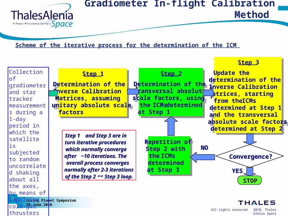
Scheme of the iterative process for the determination of the ICM
Step 1
Determination of the Inverse Calibration Matrices, assuming unitary absolute scale factors
Step 1
Determination of the Inverse Calibration Matrices, assuming unitary absolute scale factors
Step 2
Determination of the transverse absolute scale factors, using the ICMs determined at Step 1
Step 2
Determination of the transverse absolute scale factors, using the ICMs determined at Step 1
Step 3
Update the determination of the Inverse Calibration Matrices, starting from the ICMsdetermined at Step 1 and the transversal absolute scale factors determined at Step 2
Step 3
Update the determination of the Inverse Calibration Matrices, starting from the ICMsdetermined at Step 1 and the transversal absolute scale factors determined at Step 2
Repetition of Step 2 with the ICMsdetermined at Step 3
Repetition of Step 2 with the ICMsdetermined at Step 3 YES
NO
STOP
Step 1 and Step 3 are in turn iterative procedures which normally converge after ~10 iterations. The overall process converges normally after 2-3 iterations of the Step 2 Step 3 loop.
Convergence?
Step 1
Determination of the Inverse Calibration Matrices, assuming unitary absolute scale factors
Step 1
Determination of the Inverse Calibration Matrices, assuming unitary absolute scale factors
Step 2
Determination of the transverse absolute scale factors, using the ICMs determined at Step 1
Step 2
Determination of the transversal absolute scale factors, using the ICMs determined at Step 1
Step 3
Update the determination of the Inverse Calibration Matrices, starting from the ICMsdetermined at Step 1 and the transversal absolute scale factors determined at Step 2
Step 3
Update the determination of the Inverse Calibration Matrices, starting from the ICMsdetermined at Step 1 and the transversal absolute scale factors determined at Step 2
Repetition of Step 2 with the ICMsdetermined at Step 3
Repetition of Step 2 with the ICMsdetermined at Step 3 YES
NO
STOP
Step 1 and Step 3 are in turn iterative procedures which normally converge after ~10 iterations. The overall process converges normally after 2-3 iterations of the Step 2 Step 3 loop
Convergence?
Gradiometer In-flight Calibration Method
Collection of gradiometer and star tracker measurements during a 1-day period in which the satellite is subjected to random uncorrelated shaking about all the axes, by means of impulsive cold-gas thrusters and of the ion thruster.
All rights reserved 2/2010, Thales Alenia Space
Living Planet Symposium29 June 2010
10
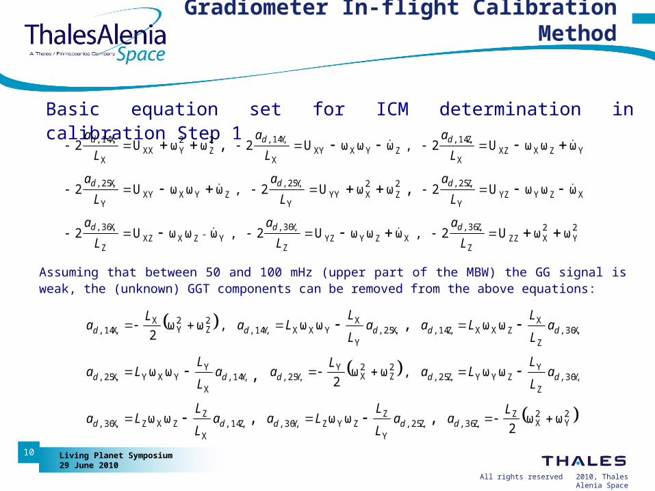
Basic equation set for ICM determination in calibration Step 1
Assuming that between 50 and 100 mHz (upper part of the MBW) the GG signal is weak, the (unknown) GGT components can be removed from the above equations:
2Y
2XZZ
Z
Z,36,XZYYZ
Z
Y,36,YZXXZ
Z
X,36,
XZYYZY
Z,25,2Z
2XYY
Y
Y,25,ZYXXY
Y
X,25,
YZXXZX
Z,14,ZYXXY
X
Y,14,2Z
2YXX
X
X,14,
ωωU2,ωωωU2,ωωωU2
ωωωU2ωωU2,ωωωU2
ωωωU2,ωωωU2ωωU2
,
,
L
a
L
a
L
a
L
a
L
a
L
a
L
a
L
a
L
a
ddd
ddd
ddd
2Y
2X
ZZ,36,Z,25,
Y
ZZYZY,36,Z,14,
X
ZZXZX,36,
Y,36,Z
YZYYZ,25,
2Z
2X
YY,25,Y,14,
X
YYXYX,25,
X,36,Z
XZXXZ,14,X,25,
Y
XYXXY,14,
2Z
2Y
XX,14,
ωω2
ωωωω
ωω,ωω2
ωω
ωωωω,ωω2
,,
,
,
Laa
L
LLaa
L
LLa
aL
LLa
Laa
L
LLa
aL
LLaa
L
LLa
La
ddddd
ddddd
ddddd
Gradiometer In-flight Calibration Method
All rights reserved 2/2010, Thales Alenia Space
Living Planet Symposium29 June 2010
11
…………………….
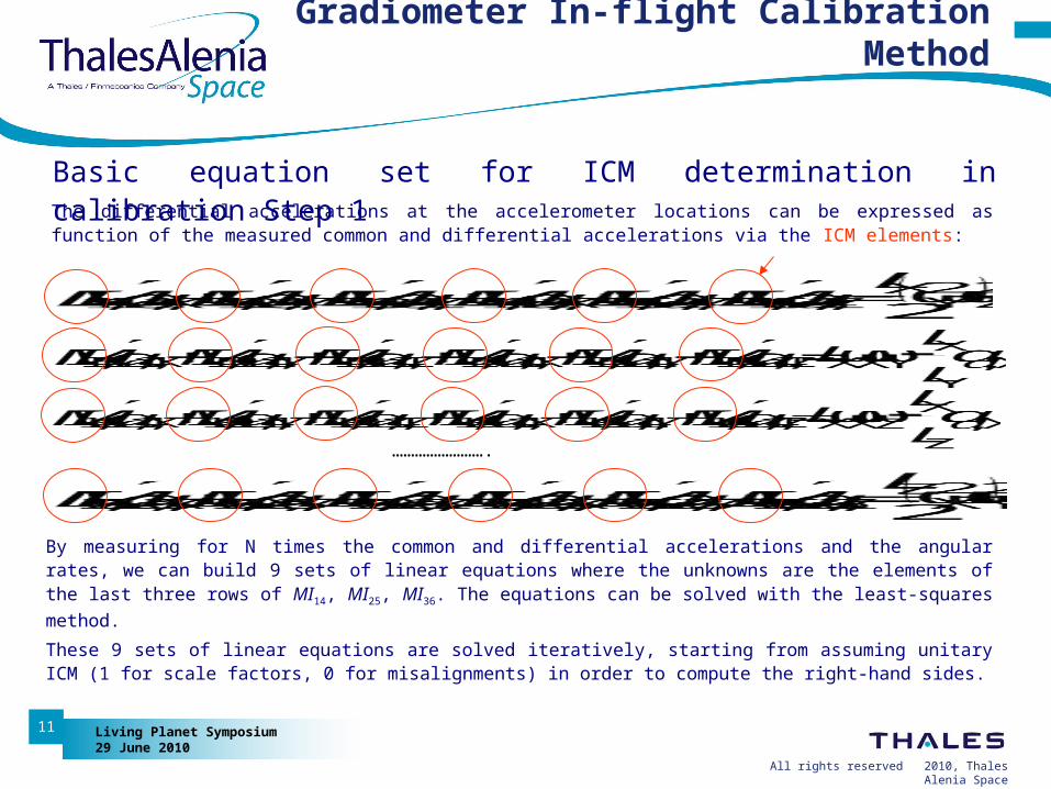
The differential accelerations at the accelerometer locations can be expressed as function of the measured common and differential accelerations via the ICM elements:
By measuring for N times the common and differential accelerations and the angular rates, we can build 9 sets of linear equations where the unknowns are the elements of the last three rows of MI14, MI25, MI36. The equations can be solved with the least-squares method.
These 9 sets of linear equations are solved iteratively, starting from assuming unitary ICM (1 for scale factors, 0 for misalignments) in order to compute the right-hand sides.
Gradiometer In-flight Calibration Method
Basic equation set for ICM determination in calibration Step 1
All rights reserved 2/2010, Thales Alenia Space
Living Planet Symposium29 June 2010
12
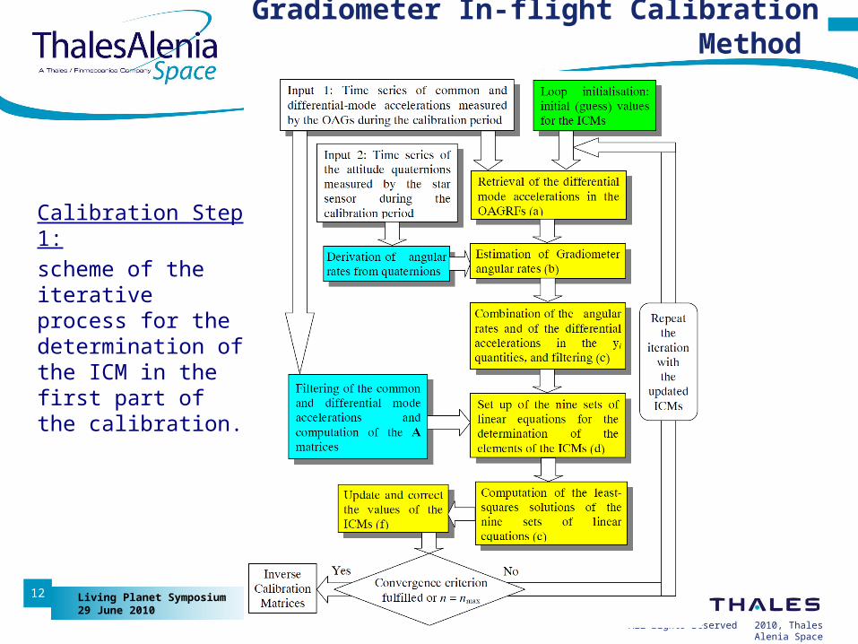
Calibration Step 1:
scheme of the iterative process for the determination of the ICM in the first part of the calibration.
Gradiometer In-flight Calibration Method
All rights reserved 2/2010, Thales Alenia Space
Living Planet Symposium29 June 2010
13
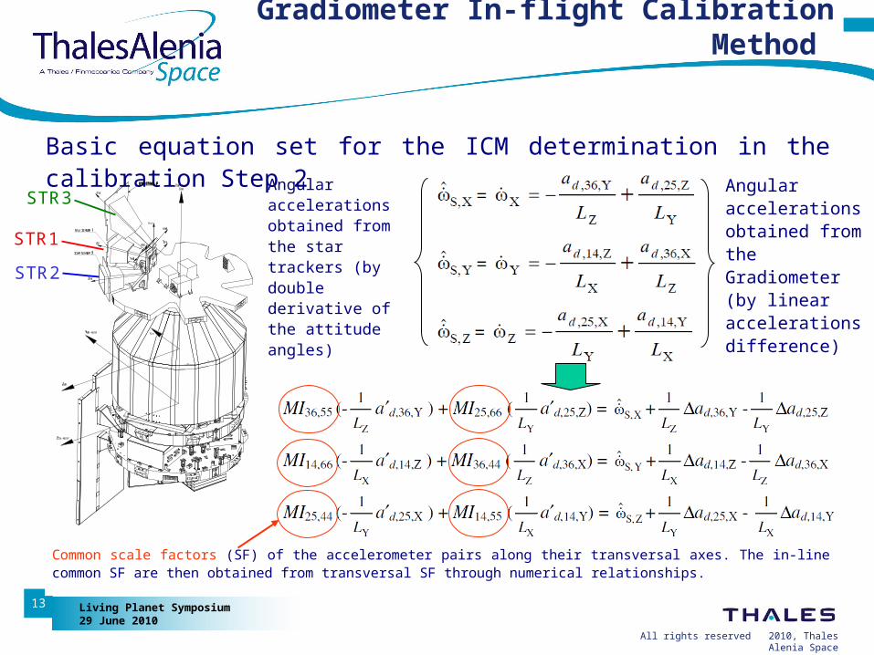
Common scale factors (SF) of the accelerometer pairs along their transversal axes. The in-line common SF are then obtained from transversal SF through numerical relationships.
Gradiometer In-flight Calibration Method
Basic equation set for the ICM determination in the calibration Step 2
Angular accelerations obtained from the star trackers (by double derivative of the attitude angles)
Angular accelerations obtained from the Gradiometer (by linear accelerations difference)
STR1
STR2
STR3

All rights reserved 2/2010, Thales Alenia Space
Living Planet Symposium29 June 2010
14
Gradiometer In-flight Calibration Results
Gradiometer in-flight calibrations since the beginning of the mission: First calibration (June 18th - 19th 2009)
Accelerometer proof mass rotation around the LS axis () controlled by 4 electrodes. Star tracker in the attitude control loop: STR1. Force bias applied.
Second calibration (Sept 28th- 29th 2009)
Proof mass rotation controlled by 4 electrodes. Star tracker in the loop: STR1.
Third calibration (Oct 8th - 9th 2009)
Proof mass rotation controlled by 2 electrodes. Star tracker in the loop: STR1.
Fourth calibration (January 11th- 12th 2010)
Proof mass rotation controlled by 2 electrodes. Star tracker in the loop: STR1.
Fifth calibration (March 4th - 5th 2010)
Proof mass rotation controlled by 2 electrodes. Star tracker in the loop: STR1.
Sixth calibration (May 6th - 7th 2010)
Proof mass rotation controlled by 2 electrodes. Star tracker in the loop: STR1.
All rights reserved 2/2010, Thales Alenia Space
Living Planet Symposium29 June 2010
15
Gradiometer In-flight Calibration Results
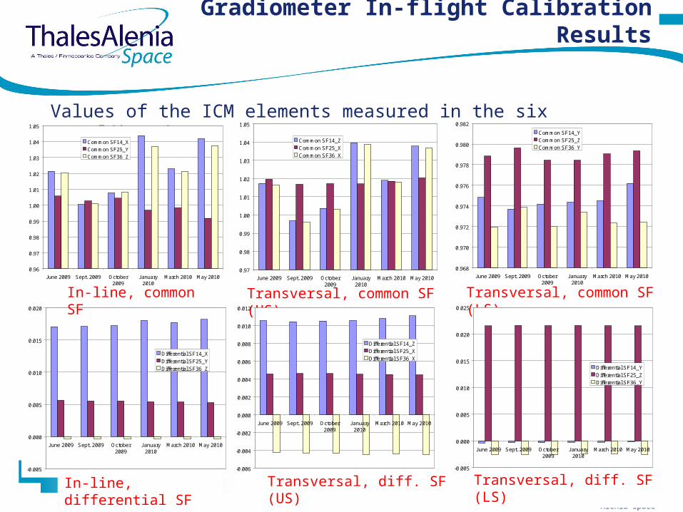
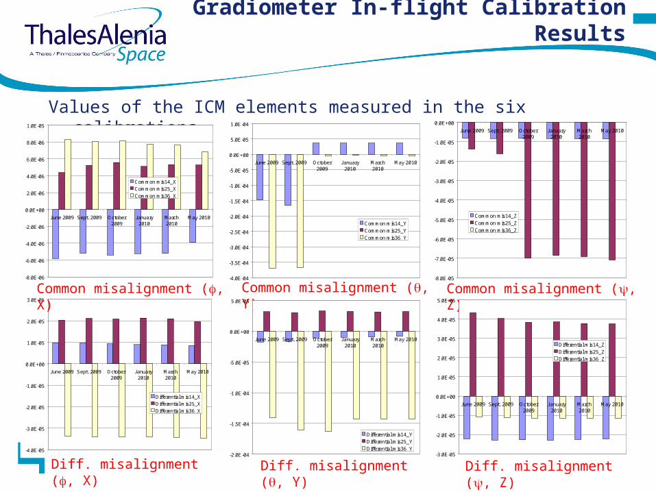
Values of the ICM elements measured in the six calibrations
Transversal, common SF (US)
Transversal, diff. SF (US)
Transversal, common SF (LS)
Transversal, diff. SF (LS)
0.96
0.97
0.98
0.99
1.00
1.01
1.02
1.03
1.04
1.05
June 2009 Sept. 2009 October2009
January2010
March 2010 May 2010
Common SF14_X
Common SF25_Y
Common SF36_Z
-0.005
0.000
0.005
0.010
0.015
0.020
June 2009 Sept. 2009 October2009
January2010
March 2010 May 2010
Differential SF14_XDifferential SF25_YDifferential SF36_Z
In-line, common SF
In-line, differential SF
0.97
0.98
0.99
1.00
1.01
1.02
1.03
1.04
1.05
June 2009 Sept. 2009 October2009
January2010
March 2010 May 2010
Common SF14_Z
Common SF25_X
Common SF36_X
-0.006
-0.004
-0.002
0.000
0.002
0.004
0.006
0.008
0.010
0.012
June 2009 Sept. 2009 October2009
January2010
March 2010 May 2010
Differential SF14_Z
Differential SF25_X
Differential SF36_X
-0.005
0.000
0.005
0.010
0.015
0.020
0.025
June 2009 Sept. 2009 October2009
January2010
March 2010 May 2010
Differential SF14_Y
Differential SF25_Z
Differential SF36_Y
0.968
0.970
0.972
0.974
0.976
0.978
0.980
0.982
June 2009 Sept. 2009 October2009
January2010
March 2010 May 2010
Common SF14_YCommon SF25_ZCommon SF36_Y
All rights reserved 2/2010, Thales Alenia Space
Living Planet Symposium29 June 2010
16
Gradiometer In-flight Calibration Results
Values of the ICM elements measured in the six calibrations
Diff. misalignment (, X)
Common misalignment (, Y)
Diff. misalignment (, Y)
Common misalignment (, Z)
Diff. misalignment (, Z)
-8.0E-06
-6.0E-06
-4.0E-06
-2.0E-06
0.0E+00
2.0E-06
4.0E-06
6.0E-06
8.0E-06
1.0E-05
June 2009 Sept. 2009 October2009
January2010
March2010
May 2010
Common mis14_X
Common mis25_X
Common mis36_X
-4.0E-05
-3.0E-05
-2.0E-05
-1.0E-05
0.0E+00
1.0E-05
2.0E-05
3.0E-05
June 2009 Sept. 2009 October2009
January2010
March2010
May 2010
Differential mis14_XDifferential mis25_XDifferential mis36_X
-4.0E-04
-3.5E-04
-3.0E-04
-2.5E-04
-2.0E-04
-1.5E-04
-1.0E-04
-5.0E-05
0.0E+00
5.0E-05
1.0E-04
June 2009 Sept. 2009 October2009
January2010
March2010
May 2010
Common mis14_Y
Common mis25_Y
Common mis36_Y
-2.0E-04
-1.5E-04
-1.0E-04
-5.0E-05
0.0E+00
5.0E-05
June 2009 Sept. 2009 October2009
January2010
March2010
May 2010
Differential mis14_Y
Differential mis25_Y
Differential mis36_Y
-8.0E-05
-7.0E-05
-6.0E-05
-5.0E-05
-4.0E-05
-3.0E-05
-2.0E-05
-1.0E-05
0.0E+00
June 2009 Sept. 2009 October2009
January2010
March2010
May 2010
Common mis14_ZCommon mis25_ZCommon mis36_Z
-3.0E-05
-2.0E-05
-1.0E-05
0.0E+00
1.0E-05
2.0E-05
3.0E-05
4.0E-05
5.0E-05
June 2009 Sept. 2009 October2009
January2010
March2010
May 2010
Differential mis14_Z
Differential mis25_Z
Differential mis36_Z
Common misalignment (, X)
All rights reserved 2/2010, Thales Alenia Space
Living Planet Symposium29 June 2010
17
Gradiometer In-flight Calibration Results
Variations of the ICM elements through the six calibrations No clear, large linear trends have been identified in the variation of the ICM
elements throughout the six calibrations, apart for the in-line common SF of the accelerometer pair 25 (~1200 ppm/month) and the in-line differential SFs of the accelerometer pairs 14 (~110 ppm/month) and 25 (~35 ppm/month).
Largest variations between successive calibrations: Jumps in the common rotations of accelerometer pairs 14, 36 around Y and of
accelerometer pair 25 around Z between September 2009 and October 2009, associated to modification of the rotation control of the accelerometer proof mass around the LS axis ().
Discontinuities of the common scale factors along the in-line and transversal US axes of accelerometer pairs 14, 36, part of which can be attributed to the measurement error of the star trackers (utilized to determine these parameters). The correlation in the variation of these common SFs is due to the relationships utilised for their determination in the TAS-I method.
Most stable parameters: alignments of the accelerometer axes to the Gradiometer reference frame.
All rights reserved 2/2010, Thales Alenia Space
Living Planet Symposium29 June 2010
18
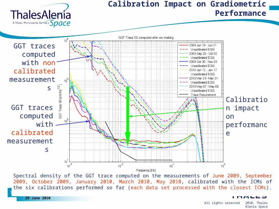
Calibration Impact on Gradiometric Performance
Spectral density of the GGT trace computed on the measurements of June 2009, September 2009, October 2009, January 2010, March 2010, May 2010, calibrated with the ICMs of the six calibrations performed so far (each data set processed with the closest ICMs).
Calibration impact on performance
GGT traces computed with non calibrated
measurements
GGT traces computed with
calibrated measurements
All rights reserved 2/2010, Thales Alenia Space
Living Planet Symposium29 June 2010
19
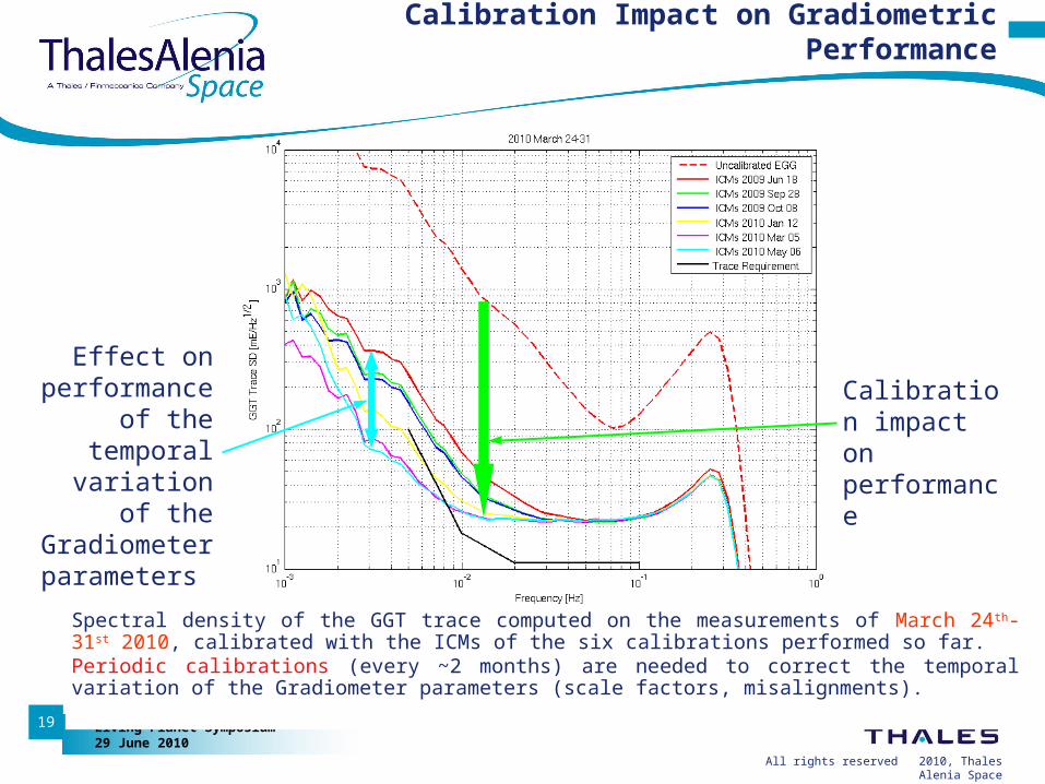
Calibration Impact on Gradiometric Performance
Spectral density of the GGT trace computed on the measurements of March 24th-31st 2010, calibrated with the ICMs of the six calibrations performed so far. Periodic calibrations (every ~2 months) are needed to correct the temporal variation of the Gradiometer parameters (scale factors, misalignments).
Calibration impact on performance
Effect on performance
of the temporal
variation of the Gradiometer parameters
All rights reserved 2/2010, Thales Alenia Space
Living Planet Symposium29 June 2010
20
Calibration Impact on Gradiometric Performance
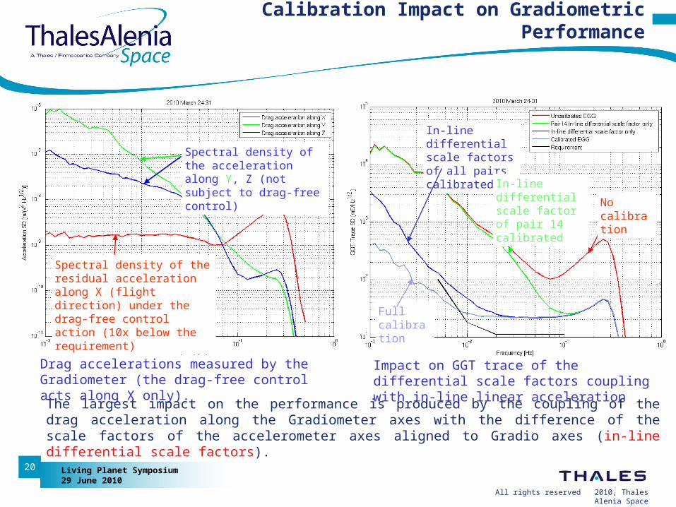
The largest impact on the performance is produced by the coupling of the drag acceleration along the Gradiometer axes with the difference of the scale factors of the accelerometer axes aligned to Gradio axes (in-line differential scale factors).
Drag accelerations measured by the Gradiometer (the drag-free control acts along X only).
Impact on GGT trace of the differential scale factors coupling with in-line linear acceleration
No calibration
Full calibration
In-line differential scale factors of all pairs calibrated
In-line differential scale factor of pair 14 calibrated
Spectral density of the residual acceleration along X (flight direction) under the drag-free control action (10x below the requirement)
Spectral density of the acceleration along Y, Z (not subject to drag-free control)
All rights reserved 2/2010, Thales Alenia Space
Living Planet Symposium29 June 2010
21
Calibration Impact on Gradiometric Performance
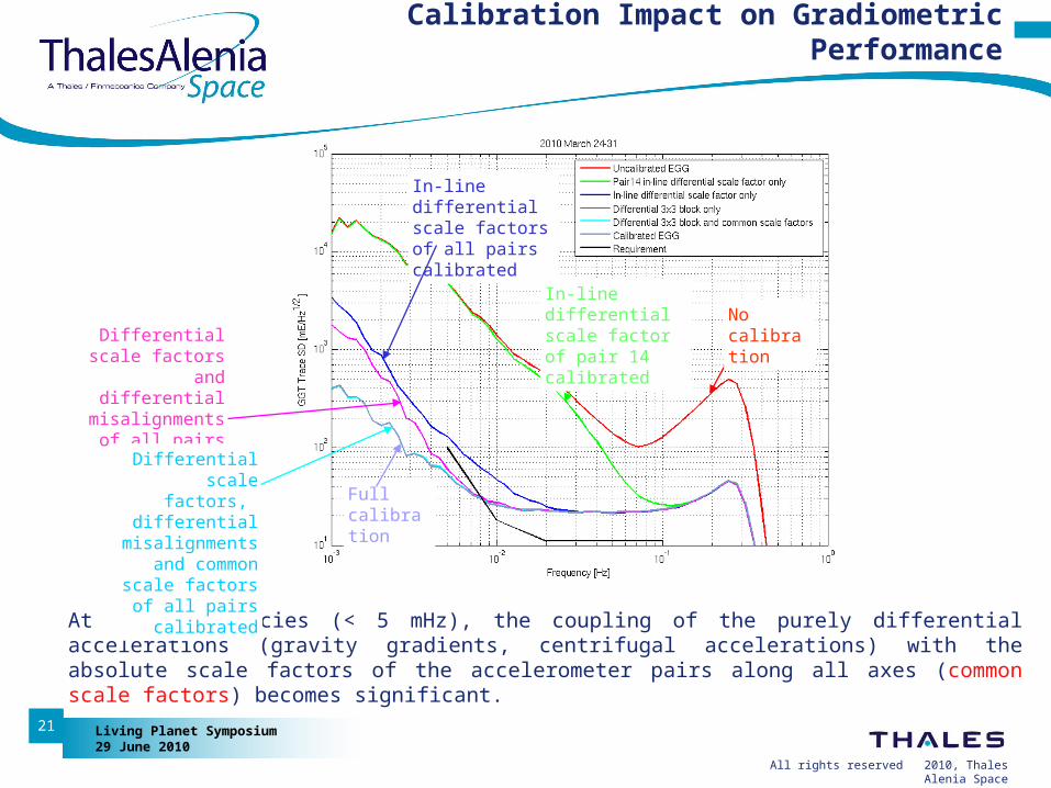
At low frequencies (< 5 mHz), the coupling of the purely differential accelerations (gravity gradients, centrifugal accelerations) with the absolute scale factors of the accelerometer pairs along all axes (common scale factors) becomes significant.
Full calibration
In-line differential scale factors of all pairs calibrated
In-line differential scale factor of pair 14 calibrated
No calibrationDifferential scale
factors and differential
misalignments of all pairs calibrated
Differential scale factors,
differential misalignments
and common scale factors of all
pairs calibrated
All rights reserved 2/2010, Thales Alenia Space
Living Planet Symposium29 June 2010
22
Calibration Impact on Gradiometric Performance
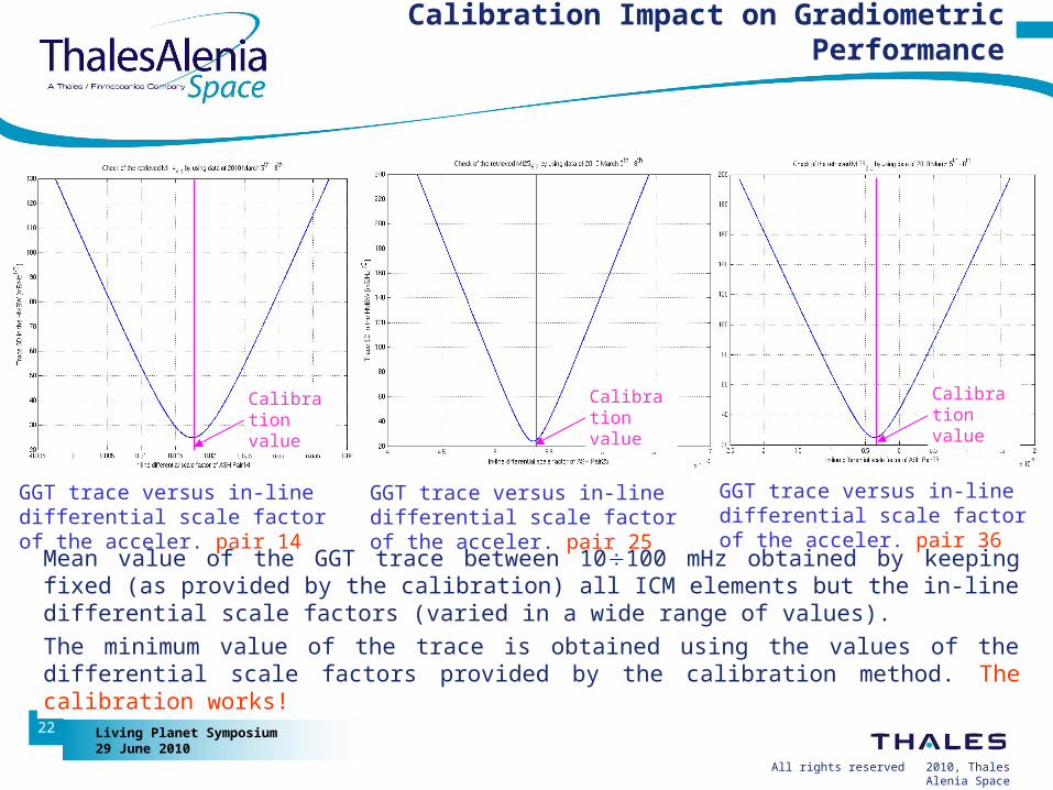
Mean value of the GGT trace between 10100 mHz obtained by keeping fixed (as provided by the calibration) all ICM elements but the in-line differential scale factors (varied in a wide range of values).
The minimum value of the trace is obtained using the values of the differential scale factors provided by the calibration method. The calibration works!
GGT trace versus in-line differential scale factor of the acceler. pair 14
GGT trace versus in-line differential scale factor of the acceler. pair 36
GGT trace versus in-line differential scale factor of the acceler. pair 25
Calibration value
Calibration value
Calibration value