Embed Size (px)
Citation preview
TECHNICAL SPECIFICATION FOR
UNDER GROUND CAR PARKINGS
NORTH DMC
Annexure – B
NORTH DELHI MUNICIPAL CORPORATION
CONSTRUCTION OF CONVENTIONAL
UNDERGROUND MULTILEVEL CAR PARKING
AT SHIVA MARKET AND
QU-BLOCK PARK PITAMPURA
NEW DELHI
TECHINCAL SPECIFICATIONS
Website : www.mcdonline.gov.in
Email: [email protected]

TECHNICAL SPECIFICATION FOR
UNDER GROUND CAR PARKINGS
NORTH DMC
Construction of Multilevel underground Car parkings at Shiva
Market Park, Pitampura and QU Block, Pitampura
TECHNICAL SPECIFICATIONS
CONTENT
S.No. Description Page
1. Civil Work 1 – 7
2. Electrical, Fire Alarm System, Public
Address and CCTV, lift etc.
8 – 67
3. Ventilation Work 68 – 80
4. Fire Fighting System 81 – 127
5. Building Management and Car 128 – 168
6. List of Makes 169 - 174

TECHNICAL SPECIFICATION FOR
UNDER GROUND CAR PARKINGS
NORTH DMC
TECHNICAL SPECIFICATIONS
CONSTRUCTION OF MULTI LEVEL UNDERGROUND CAR PARKING AT
SHIVA MARKET AND QU BLOCK PARK, PITAMPURA.
GENERAL SPECIFICATIONS:
1.0 The following General Specification shall be followed in conjunction with other
provisions of Tender Documents such as description of items, general & special
conditions of contract and any other document made part of tender document.
1.1 The civil work in general shall be carried out as per CPWD specifications, 1996
(Volume I to VI) (updated with correction slips issued up-to last date of submission of
tender) and Text of revised CPWD Specifications for Cement Mortar, Cement Concrete
and RCC Works unless otherwise specified in the nomenclature of the individual item
or in the particular specifications for civil works, (updated with correction slips issued
up-to last date of submission of tender).
1.2 Electrical works shall comply to the CPWD specifications ( part-I Internal works)
2005 & ( part-II external works) 1994 and the requirements of Indian Electricity Rules,
1956 and Indian Electricity Act – 1910 as amended up-to date.
1.3 Mechanical ventilation works, shall conform to the CPWD specifications latest versions
and for the items specifications not available in CPWD specifications, manufacturers
specifications shall be applicable.
1.3.1 Fire detection and fire fighting works shall be carried out as per CPWD
specifications and conforming to the requirements of fire department as well.
1.3.2 Car parking management, security system, intelligent vehicle access control
system and signages etc shall conform the specifications provided in the tender
document and as per manufacturer’s specifications.
2.0 For Items not covered under any of the specifications stated above, the work shall be
carried out as per Manufacturer’s Specification / as per the direction of Engineer-in-
Charge.

TECHNICAL SPECIFICATION FOR
UNDER GROUND CAR PARKINGS
NORTH DMC
SPECIFICATIONS FOR CIVIL WORKS
The work of construction of multilevel underground car parking shall be executed as per
CPWD specifications. It is understood that the contractor has visited the site and has become
familiar with site conditions before submitting their offer.
The construction drawings:
The good for construction drawings shall be issued to the contractor in the phased manner as
per requirement of construction sequence and program submitted by the contractor and
accepted by the engineer in charge.
SCOPE OF WORKS
The scope of work shall be as described hereunder but not limited ,
for completing the project as per drawings and as directed by engineer in charge:
1. REINFORCED CEMENT WORK :Exposed RCC surface of retaining
wall, columns and ceiling at basement
parking at (-1), (-2 ) and ( -3 ) Level shall not
have any paint finishes. Accordingly, contractor
shall ensure that concrete is free from any type
of honey combing, superfluous mortar , damages
/ chipping to corners, edges etc.
2. DOOR FRAMES : Aluminum frames at all locations except toilet
and W C shutters
3. DOOR SHUTTER : Wooden flush shutter in ticketing room, driver
rest room,BMS room& utility room etc.
4. FIRE RATED SHUTTER : Lift/ staircase lobby and Ventilation rooms
5. FLOOR FINISH : Cement concrete( vaccum dewatering process)
at ramps, driving ways& parking.

TECHNICAL SPECIFICATION FOR
UNDER GROUND CAR PARKINGS
NORTH DMC
: Vitrified tile at toilet, BMS room& ticketing room
: Kota stone at lift/ stair lobby, driver waiting
& utility room
: Cement concrete in ventilation room .
6. WALL CLADDING/ DADO : Ceremic glased tile up to 2850 mm/ ceiling in toilet
: Stone cladding at external surface of wall of stair
mumty, entry/ exit wall, toilet, ticketing & drivers
waiting.
: stone cladding at both sides of boundary wall.
: Aluminium composite panel ( ACP) at entry/ exit
ramp roof canopy
: Marble cladding at lift wall/ architrave
7. PAINT FINISHES : Plastic emulsion at Ticketing & BMS Room
: Oil bound distemper in balance area.
: Synthetic enemul at boundary wall & stair railings
The finishes mentioned above are indicative. The execution of works shall be carried as per
drawings issued for construction purposes and direction of engineer in charge.
PARTICULAR SPECIFICATIONS :
The specifications for non scheduled items contained in the schedule of rates shall be
followed as under:
1. BOULDER SOLING WORK
Material :
The boulder procured shall be of naturally occurred stone of the nominal single sizes ranging
from 40 mm to 150 mm. It shall be hard, strong, dense, durable and clean. The flaky and
elongated pieces shall be avoided.
The fine sand shall be as per CPWD specifications . The sand shall be filled in the voids and
whole mass shall be watered and compacted properly.

TECHNICAL SPECIFICATION FOR
UNDER GROUND CAR PARKINGS
NORTH DMC
Laying :
The soling stone of different sizes shall be laid by hand packing by skilled workers. The
soling shall be laid in layers of thickness not exceeding 300 mm.
The sequence of laying shall be such that the bigger size of stones are placed at bottom and
successive smaller size is hand packed. It is ensured that the maximum voids are filled.
Thereafter, sand is filled , watered and compacted by hand rammers or surface vibrator as per
direction of engineer in charge.
Measurements: The compacted soling mass shall be measured in cubic meter correct to two
places of decimal.
Rate: The rate shall include the cost of all material and labour involved in the operations
described above.
2. GLASS REINFORCED CONCRETE TILE FLOOR/ PAVEMENT
Material :
The glass reinforced designer cement concrete tiles shall be 25 mm thick in the size of
300mmx300mm or 400 mmx400 mm in pattern/ design as approved by engineer in charge.
The tolerance in size and thickness shall be +/- 5 mm. The minimum compressive strength
of the tiles shall be 400 kg/ cm2. The material shall only be procured from the approved
venders.
Laying :
The tiles shall be wet and laid over the sub base of lean concrete. The sub base shall be
spread with cement slurry @ 3.3 kg/ sqm. Thereafter, tiles shall be laid over 20 mm thick
cement mortar in the proportion of 1:6 (1 cement : 6 coarse sand ). While laying the tiles,
zero gap shall be maintained. The tiles with damaged corners etc. not to be used in the work.
The joints between tiles shall be filled with white cement mixed with matching pigment
approved by engineer in charge. The necessary gradient shall also be maintained in laying of
tiles. After laying of tiles, all superfluous cement mortar , grouts/ pigment shall be neatly
cleaned and water washed.

TECHNICAL SPECIFICATION FOR
UNDER GROUND CAR PARKINGS
NORTH DMC
Measurements: The GRC tile work shall be measured in square meter correct to two places
of decimal.
Rate: The rate shall include the cost of all material and labour involved in the operations
described above. However, the sub base of lean concrete shall not be covered in the item.
3. METAL CLADDING WORK
Material :
The metal cladding shall be done with 4 mm thick aluminium composite panel consisting of
0.5mm thick aluminium inner & outer skin and 3 mm thick LDPE based core. The alloy of
aluminium shall be 3105-H 24 grade conforming to BS: 1475.
The top surface of panel shall be finished with minimum 30 microns PVDF coating (
Polyvinylidene di fluoride) and coating shall conform to AAMA 2650 for exterior grade
finish. The reverse side of the panel surface shall have polyester base coating to protect
against possible corrosion.
The weight of the panel shall be 5.5 kg/ sqm and tensile strength of 4.9 Kg.mm2.
Fabrication and fixing : The panel shall be cut and bent in the profile shown in the drawing
issued. The panel with irregularities, waves , peel off area shall be sorted out and not put to
use in the work. The profile cut shall true in shape, straight, and smooth cut. The panel in
profile shall be fixed to the M S sub structure frame work. The panel joints of width of
approximately 25 mm shall be filled with weather silicone sealant of texture approved by
engineer in charge.
Aluminum flashings shall be provided at the bottom.
Measurements: ACP cladding work shall be measured in square meter correct to two
places of decimal.
Rate: The rate shall include the cost of all material and labour involved in the operations
described above. However, M S sub structure frame shall not be covered in the item and paid
separately.

TECHNICAL SPECIFICATION FOR
UNDER GROUND CAR PARKINGS
NORTH DMC
4 DRAIN BOARD FOR ROOF PARKS:
The drain board shall be of PVC , 7.3 mm high danodren shall used to drain the water which
pass through geo textile provided. The compressive resistance shall be of 120 KN/sqm and
drainage capacity of at least 4.8 liters per sqm.
Laying: The roll of the drain board shall be cut in sizes as per requirement of area to be laid.
Minimum overlapping of 100 mm shall be provided in the board in laying.
Measurements: Drain board after laying shall be measured in square meter correct to two
places of decimal.
Rate: The rate shall include the cost of all material and labour involved in the operations
described above.
5. FIRE RETARDANT DOOR SHUTTERS
Material
The Metal fire door shall quality all three criteria’s i.e. Stability, Integrity and Insulation
criteria as (per IS: 3614 )
The FR insulation filler used for the fire door will be rock wool / mineral wool of density not
lees than 96 kg/m3.
The door frame and panel shutter shall be manufactured using 16 gauge prime galvanized
steel sheets.
The fire seal will be of size 10mm x 4mm imported shall be used for smoke sealing will be
from Astroflame or Pemko.
The internal flaming of the door would have the C channel of size not less than 52 mm of
1.6mm thickness on all the perimeter of the door and horizontal and vertical sections also.
The hinges for fixing the shutter shall be of Dorma/ Ingersoll rand of size 100x75x 3 mm,
stainless steel and D type pull/pushof size 250mm long & 19 mm diameter.
Fixing : The fire door shutter supplied from the approved vender shall be fixed in true
alignment of the door opening.

TECHNICAL SPECIFICATION FOR
UNDER GROUND CAR PARKINGS
NORTH DMC
Rate: The rate shall include the cost of all material and labour involved in the operations
described above.
Measurements: Fire rated door shutter shall be measured in square meter correct to two
places of decimal. Area of door opening shall be measured.
Fire rated glass for vision panel.
The thickness of the fire rated glass should not be less than 5mm.
The visible transmission of the fire rated glass should not be less than 88%.
The fire rated glass should be able to withstand hose stream test.
The glass should be tested as per BS: 476 part -2 1987 and ISO: 3001.
The size vision panel shall be as specified in the schedule of rates which shall excluding hide
portion in the rebate. These shall be measured in number.
Panic Exit Devices:
The fire rated double leaf panic bars of ingersoll Rand Briton / Dorma PHA series shall be
conform along with the door as per IS: 3614 part II. The shall be measured in pair for double
leaf doors.
Landscaping Work :
1. The Contractor shall submit his drawings for proposed plan in accordance with BOQ
items for approval of Engineer-in-Charge for approval before commencement.
2. The plants shrubs and climbers to be planted of sound health.
TECHNICAL SPECIFICATION FOR
UNDER GROUND CAR PARKINGS
NORTH DMC
THE SPECIFICATIONS FOR ELECTRICAL, FIRE ALARM SYSTEM, PUBLIC
ADDRESS, CCTV, LIFT ETC.
Sub Station Equipment
The work of substation and other connected work shall be carried out as per General
Specifications for Electrical Works (Part-IV - Substations) 1982 as amended up to date and
General Specifications for Electrical Works (Part
I-Internal) 1994 and General Specifications for Electrical Works
(Part-II-External) 1995 as amended up to date except the following changes
Reference to clause numbers of specifications is also given.
Section 1. Package Substation
1.1 The complete package substation shall be factory assembled with separate access to
transformer, HT and LT compartments. It shall be possible to install the package sub-
station in congested areas with blocked walls on two sides.
1.2 The substation enclosure shall be made from 2mm thick CRCA sheet
steel with Load bearing members of 3mm thick CRCA sheet steel. The enclosure
shall be tested for internal Arc with stand capacity as per IEC-61330. The
enclosure should not require any artificial cooling through exhaust fans
etc. it should be naturally Air-cooled.
1.3 There should be proper provision of Internal Lighting of MV and LV
compartments. Sufficient space should be available inside the package sub
station for any operating personnel to operate and work on MV and LV
equipment in case of a need for performing any maintenance activity.
1.4 Safety notices and faults indicator outside the package substation
to indicate any fault.
1.5 Package sub station must be delivered in one single indivisible
volume to avoid assembly of components at site.
The package substation will have the followings:

TECHNICAL SPECIFICATION FOR
UNDER GROUND CAR PARKINGS
NORTH DMC
H.T. Side :-
The H.T. Side panel shall be SF6 insulated single board comprising of two
ring switch type isolators and one tee off SF6 insulated vacuum circuit
breaker having an arrangement for incoming and outgoing connections. All
live and switching parts are enclosed in 2 -mm thick stainless steel tank
filled with SF6 gas.
3 way 11kV indoor non extensible free standing 630 Amps metal clad SF6
insulated Isolators comprising of fault making/load breaking switches and
one number 400A Tee off circuit breaker complete with all accessories as
follows : -
(i) Self powered IDMT relay for circuit breakers
(ii) The ring switches and Tee-off circuit breaker are provided with integrated earthing
switches with making capacity.
(iii) Live capacitive cable indicator for ring switches
(iv) SF6 Gas pressure indicator
(v) Pad locking facility
(vi) Shunt trip coil rated for 230 V AC
(vii) HT connections of RMU through fully insulated cable and sealing kits.
Transformer
The transformer shall be 630 KVA ONAN Cooled oil cooled having no load winding ratio
11000/433 volts. The connections between HT Switchgear and transformer shall be through
fully insulated cable and sealing kits. The
transformer shall be corrugated tank hermetically sealed transformer with off load tap
changer of +5% to -5% @ 2.5%. If required, the Transformer can be 33kV/433V
also. Cooling can also be Dry Type with OFTC.
LV Switchgear
The LV switchgear shall be provided with Air Circuit Breaker on
Incomer and MCCBs as outgoing of suitable rating. LV switchgear shall have
provision for with drawing ACB/MCCBs and shall have provision for rear

TECHNICAL SPECIFICATION FOR
UNDER GROUND CAR PARKINGS
NORTH DMC
connections through insulated bus bars to transformer LV. All ACB and all
MCCBs shall be of three pole design. Additionally Automatic Power Factor
Correction Panel can also be incorporated for maintaining the Power Factor
to desired levels.
Earthing
The work shall be carried out as per relevant specifications.
Earthing shall be done in the presence of Engineer-in-charge or his
authorized representative.
Single Line Diagram of PSS
SPECIFICATION OF TRANSFORMER
1. Voltage Ratio 11kV/433V
2. Type of construction Hermetically Sealed ONAN; OR Dry Type
3. Insulation Class A
4. Tapping on HV Off Load + 5% to -5% @2.5% each step
5. Enclosure Housed in Pre stressed Enclosure, Having degree of
Protections IP- 23D.
6. Applicable standard IS: 2026 - amended up to date
7. HV Termination Suitable for XLPE Cable bottom entry
8. LV Termination Suitable for connection with LV Switchgear
9. Fittings (i)Lifting Lugs
(ii) Roller (bi-directional) Winding Temperature
indicator with Contacts to be provided for Alarm &
Tripping.
10. Testing Routine acceptance test as per IS- 2026 to be
witnessed by representation of engineer-In-Charge at
his discretion.
11. Installation to be installed in enclosure Power cable from
Transformer to HV Panel to be provided.
TECHNICAL SPECIFICATION FOR
UNDER GROUND CAR PARKINGS
NORTH DMC
SPECIFICATION FOR H.V. Switchgear
1. Applicable standard IS: 13118 amended up to date
2. Rating 12KV, 20 kA
3. Circuit Breaker SF6 insulated HT isolators as Incomer and
Vacuum Circuit Breaker as Outgoing
4. Operating Mechanism Manual charging
5. Tripping arrangement Shunt trip with self powered relay
6. Bus bar Copper bus bar suitable for 400 Amps Provided
with heat shrinkable sleeve.
7. C.T. Double core, Cast Resin
(a) 15 VA Burden for protection with 5P-10 accuracy
(b) 15 VA Burden for metering with Class-I accuracy.
8. Relays & Accessories Microprocessor based self powered relay For
overcurrent and earth fault protection.
9. Indicating Lamps/Push Button All standard indicating lamp like phases,
ON/OFF breaker charged etc. heater switch,
10. Cable Termination XLPE HT Cable of size 3 x 185 sq.mm. (Incoming)
entry bottom. Insulated HT cable with Sealing
kits to transformer.
TECHNICAL SPECIFICATION FOR DIESEL GENERATING SET
DIESEL ENGINE
Reliable rugged diesel engine AIR /Water cooled, electric start, four stroke multi cylinder,
conforming to relevant IS/BS with 10% overloading for one hour in any twelve hours. The
engine will be fitted with following accessories:
COOLING SYSTEM
- Blower / Radiator
- Automatic belt tensioning device / Centrifugal water pump
TECHNICAL SPECIFICATION FOR
UNDER GROUND CAR PARKINGS
NORTH DMC
EXHAUST SYSTEM
- Exhaust manifold
- Flexible pipe for silencer
FUEL SYSTEM
- Fuel pump
- Fuel injectors
- Fuel filter
LUB OIL SYSTEM
- Lub oil pump
- Lub oil filter
AIR SYSTEM
- Air intake manifold
- Air cleaner assembly
GOVERNOR
- Mechanical
STARTING SYSTEM
- Electric starting – 12V
- Battery charging alternator
COUPLING ARRANGEMENT
- Flexible coupling
- Flywheel to suit flexible coupling
- Flywheel housing
ENGINE INSTRUMENT PANEL
- Starting switch with key
- Lub oil pressure gauge

TECHNICAL SPECIFICATION FOR
UNDER GROUND CAR PARKINGS
NORTH DMC
- Battery charging ammeter
SAFETIES
- Low lub oil pressure
- High water temperature (Only for water cooled engine)
MANUALS
- Engine operation and maintenance chart
- Parts catalogue
- Engine routine test certificate
- Engine warranty card
ALTERNATOR
Synchronous three phase alternator of make suitable for continuous operation at 1500RPM
generating 415lts at 0.8power factor (lag) suitable for 50Hz, Three phase, 4wire, system. The
alternator shall be self excited, self regulated, foot mounted fitted with ball and/or roller
bearings. The alternator will generally conforming to BS:2613/ IS:4722.

TECHNICAL SPECIFICATION FOR
UNDER GROUND CAR PARKINGS
NORTH DMC
ACCESSORIES
BASE FRAME
Heavy duty base frame of sturdy design made of M.S. channel with necessary reinforcement
and pre drilled holes
FUEL TANK
Daily service fuel tank made out of 14SWG MS sheet suitable for 100Litres complete with
drain plug, air vent, inlet and outlet connection
BATTERY
One no. Battery of 12V each in dry and uncharged conditions with its leads of
Exide/Kirloskar make.
AUTOMATIC MAINS FAILURE PANEL
The panel will be made out of fabricated sheet steel suitable for indoor mounting installation,
hinged front panel door for easy accessibility and suitable rated bus bars complete with
internal wiring, fuses with suitable provision for connecting incoming and outgoing cables.
The panel will be fitted with following instruments:
Alternator contactor of suitable rating with over load relay and HRC fuses for short circuit
protection
Main contactor of suitable rating
One ammeter
One voltmeter
One frequency meter
One set of mains supply voltage monitor to identify low voltage/ complete failure and initiate
necessary signal for operation of automatic control gear.
Set of push buttons for Start, Stop, Reset, Acknowledge
Master switch for Auto/Manual/Test/Off
One set of indicating lamps for indicating
- Load on mains
- Load on set

TECHNICAL SPECIFICATION FOR
UNDER GROUND CAR PARKINGS
NORTH DMC
- Set fails to start
- Low lub oil pressure
- Battery charger ON
One hooter
Battery charger for charging battery when set is not in operation, connecting to the load side
so that it will energized from the mains. The battery charger will comprise of the following:
- Transformer of suitable capacity
- Rectifier
- D.C.ammeter
- D.C.voltmeter
- Charger rate selector switch for trickle or boost charging
All control fuses will be so located as to be easily accessible for replacement
Relay section will comprise of the following
- Automatic starting of D.G.set in the event of mains voltage failure/ falling below a preset
value
- When the main supply is restored, it’s quality will be monitored for a period of set time,
then load is automatically transferred on the mains and the D.G.set will shut down after a
preset idle running period
- In the event of failure of diesel engine to start on failure of mains supply on one attempt,
two more starting impulse will be automatically given and if still the engine does not start
due to some defects within thirty seconds of first starting impulse, it will get disconnected
and locked out automatically and audio and visual signal will operate
- In the event of failure of diesel generating set due to faulty starting, the mains supply
contactor will get energized without any delay on the restoration of mains supply
The circuitry will make use of minimum number of relays and control wiring will be neatly
provided with adequate size of copper conductor cable of suitable cross section voltage
grading and tag number at either end.
In the manual operation the diesel generating set will be started by the attendant by pressing
start push button irrespective of the conditions of the main supply. Thus with this

TECHNICAL SPECIFICATION FOR
UNDER GROUND CAR PARKINGS
NORTH DMC
arrangement it will be possible to exercise routine test of the diesel generating set on the load
without interrupting the supply of essential circuit.
In the test mode of operation conditions similar to mains failure will be simulated by
operating the master switch on the Test.
By pass system with the help of two nos. changeover switch of suitable rating
Acoustic Enclosure:
Acoustic enclosure shall be powder coated and fabricated out of 16 SWG CRCA MS sheet.
The silent canopy shall be of nut bolt type construction. Critical processes of punching is
done on CNC machines to maintain dimensional accuracy of holes within 0.1 mm. Powder
coating is done after seven-tank surface preparation process of sheet metal. Canopy panel and
doors shall have inside lining of FIRE-RETARDANT foam as acoustic material. Four hinged
doors shall be provided to canopy, one door shall have glass window for control panel.
Base Frame:
Base frame is fabricated either in ISMC channel or in sheet metal. The base frame will be
primer coated and painted. The base frame is rugged in construction and designed for
mounting Diesel engine and alternator close coupled, with cross members mounted on AVM.
The base frame shall have provision for mounting of acoustic enclosure & control panel on it.
The base frame is having provision of lifting hook for convenient lifting of complete set, i.e.
along with canopy, engine and alternator.
Color Scheme
The base plate and top is powder coated with OXFORD BLUE/PEPSI BLUE, the canopy is
powder coated with IVORY color.
Performance Parameters
The average sound level, when measured in green field condition (ISO 3744 OR 8528 PT
10) at 1-meter distance from all four sides shall be less than 75-dBA averages or as per CPCB
norms.

TECHNICAL SPECIFICATION FOR
UNDER GROUND CAR PARKINGS
NORTH DMC
The average stabilized hot air temperature rise with in the canopy is maintained with in 10 C
over and above ambient temperature.
CANOPY FEATURES
Canopy fabricated on machines with dimensional accuracy of 1mm.
Canopy is powder coated after passing through seven tank processes.
Canopy is lined with acoustic foam, which is non-igniting /Fire Retardant (confirming to BS
4735/BIS 7888).
No grouting required on the ground, only a level surface capable of withstanding the DG
weight.
Designed for installation in open-air conditions.
Lockable doors provided.
Lockable fuel filling arrangement provided external to the canopy.
Residential Silencer is housed in the canopy.
Externally accessible emergency stop button.
The exhaust gases shall be taken out through a suitable flexible pipe to prevent any back
pressure on the engine.
Thermal Insulation:
The exhaust system and noise suppressor shall be provided with thermal insulation by using
fire retardant/non igniting foam conforming to BIS7888/BS 4735 to prevent excess heat
radiation on the engine and safe for operator
Noise suppressor: (Silencer)
Absorption type Non resistance Residential Silencer insulated from inside with glass wool
shall be provided to suppress exhaust noise from the engine.
Wiring and Lighting:
PVC copper wire concealed in flexible conduit with florescent tube light/bulb with MCB
shall be provided.

TECHNICAL SPECIFICATION FOR
UNDER GROUND CAR PARKINGS
NORTH DMC
Surface Treatment-Painting:
The enclosure surface shall be suitably treated for degreasing, de-rusting and phosphating.
High quality powder coat treatment/paint shall be used.
Canopy lights: one no. DC bulb to be fitted with suitable toggle switch and wiring.
Temperature rise inside the canopy
The maximum permissible temperature rise above the ambient shall be 10oC.
Emergency Push Stop Button
The canopy shall have provision of emergency push button, which shall be housed in a
protective enclosure with a glass front.
Performance:
The sound level shall be less than 75 dbA at a distance of 1 meter. The temperature difference
between ambient and air inlet at air cleaner within the enclosure will be maintained well
within 5-7 deg centigrade. The measurement of noise will be as per ISO 3744/ISO 8528 (part
10) standard. This meets CPCB norms.
All other requirements that are essential to make the DG set compliant to CPCB norms for
noise reduction shall form part of technical requirements.

TECHNICAL SPECIFICATION FOR
UNDER GROUND CAR PARKINGS
NORTH DMC
SPECIFICATION FOR INTELLIGENT FIRE ALARM SYSTEM
PART 1.0 -GENERAL
Description
A. The fire alarm system shall include furnishing, installation, and connection of the
Analog/Addressable Microprocessor based LCD/LED Fire Alarm Control Panel
consisting of system cabinet(s), main chassis with power supply, with or without
UDACT dialer, stand-by batteries, initiating and indicating, optional city tie/reverse
polarity module, optional relay modules, detection and signaling devices, and any
auxiliary modules, remote annunciator assemblies, and miscellaneous peripheral
devices to form a complete coordinated system ready for operation as shown on the
drawings or herein specified.
B. The fire alarm system shall comply with requirements of NFPA Standard No. 72 for
protected premises signaling systems except as modified and supplemented by this
specification. The system field wiring shall be supervised electrically. The system and
all associated equipment shall be fully approved and listed by the following agency
and regulatory controls:
1. System:
a. Must comply with applicable National, State, and/or local Building code
recognized at time of installation.
b. Must comply with NFPA 101 70, 72 fire alarm installation standard
recognized at time of installation.
c. Installation must comply with requirements of Local Authority Having
Jurisdiction.
2. Devices & Control equipment:
a. Equipment described here in must be UL listed under the current issue of the
standard indicated:

TECHNICAL SPECIFICATION FOR
UNDER GROUND CAR PARKINGS
NORTH DMC
b. Manual fire alarm stations No. 38
c. Heat detectors: No. 521
d. Smoke detectors for Fire Protective Signaling Systems: No. 268
e. Audible signal devices: NO. 464
f. Control Units for Fie Protective Signaling systems: No. 864
g. Visual Notification Appliances: 1971
h. Power Supplies for Fire Protective Signaling Systems: No. 1481
i. Smoke Detectors for Duct Applications: No. 268A
j. Water flow Indicators for Fire Protective Signaling Systems: No. 346
Submittals and Shop drawings:
A. Sufficient information shall be clearly presented and shall include manufacturer’s
name, model numbers, power requirements, equipment layout, device arrangement
and complete wiring.
B. Sequence and description of operation.
C. Product Data for each type of equipment, initiating device, signal device, peripheral
device and cable provided on the project.
D. Shop drawings shall include battery calculations, floor plans and wiring diagrams.
Operation Manual :
Operation manual shall include:
1. Installation instructions for use by installing contractor.
2. Operational instructions or manual for use by building personnel, including name
and phone number of service representative.
3. Maintenance instructions as required for use by building personnel.
4. Copy of approved shop drawings.
Basic System
The fire detection system shall be capable of integrating multiple control command
TECHNICAL SPECIFICATION FOR
UNDER GROUND CAR PARKINGS
NORTH DMC
centers and remote network annunciators. Each panel shall be capable of fire detection,
equipment supervision and control, alarm management, and historical data collection and
archiving, and of integrating multiple annunciator units and remote command centers,
each capable of alarm display and system control functions. Up to 254 units may be
networked together utilizing "Peer to Peer" communication technology. Systems that are
of the OEM nature (under private label) and not fully field programmable will not be
considered. The fire detection system shall consist of the following:
Network capability of up to 254 units
Touch screen color graphics capability
Stand alone capability of each control unit on loss of data channel
Conventional and Analog Devices
250 software groups/zones
14.5" wide cabinet construction to ensure fitting between wall studs
Portable Operator's Terminals (POT)
Up to 16 Class "B" or 8 Class “A" intelligent SLC's
Up to 16 Class "B" or 8 Class "A" conventional zones (IDC’s)
8 Class "B" or 4 Class "A" notification circuits (NAC’s)
Minimum 10Amp power supply
Field programmable
Alarm/Trouble/Supervisory LED's per circuit
Individual ground fault detection and reporting by circuit
80 character back-lighted LCD read-out
60 characters dedicated to user text messaging per device/circuit

TECHNICAL SPECIFICATION FOR
UNDER GROUND CAR PARKINGS
NORTH DMC
The system shall permit expansion of both capacity and functionality through the addition
of units, modules, addressable devices and detectors.
High-speed data transfer rates for alarm reporting, quick report generation from multiple
systems/transponders and upload/download capability between network systems. The
maximum response time shall be 5 seconds between initiation of alarm and signal output.
Each control unit shall support a minimum of 1584 addressable devices in Class “A”
Loop wiring & 3168 addressable devices in Class ”B" Loop wiring. The entire "peer-to-
peer" network shall have a minimum capacity of 402336 intelligent points.
Each unit shall have sufficient memory to support its own operating system and databases
including:
Fire Management
Alarm Management
Historical/Trend Data
Maintenance Support Applications
Custom Processes
Operator I/O
Expandability: The system shall be expandable in nature and shall permit easy expansion
through the addition of software applications, additional units and devices.
Serial Communication Ports: provide data communication ports for simultaneous
operation of devices such as industry standard printers, programming terminal, personal
computer, transponder and annunciators.
Integrated on-line Diagnostics: Each unit shall continuously perform self-diagnostics,
communication diagnostics and diagnostics on all subsidiary equipment.
Surge and Transient Protection: Each unit shall provide isolation and transient protection
at all network terminations and all field point terminations to suppress induced voltage
transients where required.

TECHNICAL SPECIFICATION FOR
UNDER GROUND CAR PARKINGS
NORTH DMC
1.5 System Software
All necessary software to form a complete operating system as described in this
specification shall be provided.
The software programs specified in this section shall be provided as an integral part of
the unit and shall not be dependent upon any higher level computer for execution.
Status Change Report: All alarm or point change reports shall include the point's
English language description, and the time and date of occurrence.
Report Routing: Alarm reports shall be archived for future recall.
Alarm Messages: In addition to the point's description and the time and date, the user
shall be able to print, display or store a custom alarm message to more fully describe
the alarm condition or direct operator response.
Each control unit shall be capable of storing a library of at least 1000 events. The
event log shall have the ability to be printed via a parallel printer port built-into the
FACP.
The FACP shall have a parallel printer port which allows the internal software the
ability to print the following reports:
i. System event log
ii. Sensitivity for all devices
iii. Relation routing, this shows all input and output relationships of
the entire system
Alarm Verification: The alarm verification feature shall be used to delay acceptance
of alarms until they can be confirmed, and shall meet all applicable code requirements
and standards. Any or all circuits may be selected for verification through field
configuration, which shall be done without removal of an EPROM. If a circuit is
selected for alarm verification, it will only verify two-wire smoke detectors. Contact
devices, such as manual stations, connected to a verified circuit will be discriminated
and will not be verified.

TECHNICAL SPECIFICATION FOR
UNDER GROUND CAR PARKINGS
NORTH DMC
When the unit detects an alarm on an initiating circuit programmed for alarm
verification, the unit shall automatically reset the power to that circuit.
If the alarm condition is still present after a pre-set time period of 30 seconds, then the
system will automatically enter the Alarm mode.
History Mode: The system shall be able to store and display at least 1000 system
events that have occurred in a non-volatile buffer memory. Display of these events
shall be accomplished on-site through the use of the front control panel indicators and
switches.
Field Configurable: The system shall be fully configurable and expandable at the
owner's site without the need for EPROM programmers. All configurations shall be
accomplished through downloading of programs from a computer. Reconfiguration
shall not require knowledge of any programming languages or require any special
training. All programs shall be stored in non-volatile memory. Entry into program
mode shall require a special key and a special password entered into the front panel.
Releasing Function: The notification appliance circuit shall be software configurable
for Continuous Output, Strobes, Door Holders and releasing functions. The panel will
support Abort and Hold operation as well as have Cross Zoning.
The software residing in the FACP shall be capable of reporting initiating devices
even if they are not in the database. In the event that an initiating device, which is not
in the database, reports an alarm state, the FACP shall turn on all Notification
Appliance Circuits. This ensures all devices are active, whether they are programmed
in the database or not. Panels which do not respond to un-programmed devices in
alarm shall not be considered equal.
1.6 Networking
If utilized or for future use, the network shall be Style 7 wiring, with each control unit
talking directly with two other units and the network will be a closed loop. Units
which require a host or head end controller will not be accepted.
The network will be "peer-to-peer" with each unit generating commands to other units
as required.

TECHNICAL SPECIFICATION FOR
UNDER GROUND CAR PARKINGS
NORTH DMC
System architecture in networked configuration shall eliminate dependence upon any
single control unit for alarm reporting and control execution. Each control unit shall
operate independently by performing its own specified control, alarm management,
and historical data collection. The failure of any single component or network
connection shall not interrupt the operation of the balance of the system.
Control units on the network shall be able to send control commands directly to any
other unit on the network without dependence upon a central processing unit.
Optionally, each unit can, through programming, send operating commands, such as
Acknowledge, to other units on the network.
Prioritization: Each unit shall send commands to other units on the network based
upon the priority of the initiating signal. Alarm events/commands shall be sent before
supervisory conditions, which will be sent before commands for a Trouble condition.
In case of a partial communications failure, each unit will continue to send commands
to those units it can still communicate with.
Each unit will be able to work in a stand-alone mode in case of a total loss of network
communications.
Any control unit in the network can be made the master unit of the network by
software changes only.
Each control unit will have error detection, correction, and retransmissions to
guarantee data integrity.
Remote Annunciators/Command Centers will be an equal peer in the network.
1.7 Sequence of Operation
A. When a fire alarm condition is detected by one of the system initiating devices, the
following shall occur:
a. All automatic programs assigned to the alarm point shall be executed and the

TECHNICAL SPECIFICATION FOR
UNDER GROUND CAR PARKINGS
NORTH DMC
associated indicating devices and relays activated.
b. The System Alarm on appropriate unit will indicate an alert condition.
c. The corresponding zone(s) in alert alarm will be indicated.
d. Second stage operation shall occur when a key is inserted into the key-
operated switch of any manual pull station causing all fire alarm speakers/bells
to sound the general alarm (evacuation) at a rate of 120 strokes per minute
throughout the building.
e. If the fire alarm condition is not acknowledged at the unit within five (5)
minutes of the sounding of the first stage alarm, the fire alarm system shall
automatically indicate a second stage alarm causing all bells in the building to
sound the general alarm (evacuation) throughout the building. Activation of
the second stage shall be identified at the operator's workstation.
f. Activate all control by event functions related to the alarm.
g. Send signal to U.L. Certified monitoring central station.
h. Fan systems, i.e., shutdown, exhaust and pressurization operations to be
initiated.
i. Doors with hold open devices shall be signaled to release.
When a trouble condition is detected by one of the system initiating or indicating
circuits, the following functions shall immediately occur:
System Trouble will be indicted on the unit and system annunciator(s).
A local trouble-sounding device in the unit and annunciator shall be activated. This
sound shall be distinct from the alarm sound.
The trouble for the corresponding initiating or indicating circuit shall be indicated on
the unit.
The appropriate message will appear on the LCD display.

TECHNICAL SPECIFICATION FOR
UNDER GROUND CAR PARKINGS
NORTH DMC
1.8 Conventional Interface Module
Any Initiating Circuit may be configured to be a Supervisory Circuit. If so configured,
it will not activate the System Alarm indication when a supervisory condition is
detected but will instead activate a separate supervisory indication. Open-circuit
conditions will be reported as trouble and must be differentiated from supervisory
conditions.
Each circuit shall be definable in software as an alarm or supervisory circuit.
1.9 Analog Module
Each network control panel shall be capable of supporting 8 class “A” or 16 class "B"
SLC circuits within one cabinet.
Each Intelligent Loop circuit shall be capable of supporting up to 198 (Class A or Class
B) intelligent devices consisting of 99 intelligent detectors and 99 addressable modules
per loop. The basic unit shall be capable of supporting up to two (2) modules. Each
module has four (4) class A or eight (8) class B circuits.
One analog interface module shall monitor and control up to four Class A or eight Class
B loops of intelligent detectors and addressable modules. The analog interface board
shall contain its own microprocessor control.
The analog interface board shall communicate and provide power to all devices on its
loop over a single pair of wires. For Class B operation, the loop is not returned and
branch circuits ("T-tap") connections may be made off of the loop. Class A operation
shall be available.
The analog interface board shall receive analog information from all intelligent
detectors and shall process this information to determine normal, alarm, supervisory or
trouble conditions. The analog information may also be used for automatic test and
determination of maintenance requirements.
It shall be possible to display on the control unit LCD display, the current analog value
of any addressable device, as well as the programmed trip points.

TECHNICAL SPECIFICATION FOR
UNDER GROUND CAR PARKINGS
NORTH DMC
Communication with all connected devices shall be performed every 5 seconds or less.
Average time to detect an alarm shall be less than 5 seconds (longer for alarm
verification detectors).
PART 2- FIRE ALARM EQUIPMENT
2.0 Control Panel
The CPU shall communicate with the operator interface, LCD display, LED display
and control all other modules in the unit. Removal, disconnection or failure of any
control unit module shall be detected and reported by the Central Processing Unit.
The CPU shall contain and execute all control-by-event programs for specific action to
be taken if a fire situation is detected in the system. Such control-by-event programs
shall be held in non-volatile programmable memory, and shall not be lost even if
system primary and secondary power failure occurs. The CPU shall also provide a
real time clock for time annotation on the display and remote optional printer.
2.1 Notification Circuits
The Control Unit shall provide up to 8 fully supervised Class B notification circuits.
The notification circuit capacity shall be 1.0 amperes maximum per circuit. If a short
circuit trouble occurs on one of the notification circuits it will not affect the operation
of the remaining circuits.
2.2 Function Relays
The Control Unit shall provide 4 sets of Form "C" relay contacts rated at 2 A at 30
VDC. These relays may be programmed to activate on alarm from any initiating
zone or any combination of initiating zones, analog devices or addressable
modules.
2.3 System Relays
The Control Unit shall provide 3 sets of Form "C" relay contacts rated at 2 A at 30
VDC. These relays have a fixed operation, alarm, supervisory, and trouble.

TECHNICAL SPECIFICATION FOR
UNDER GROUND CAR PARKINGS
NORTH DMC
2.4 Operator Display
The operator display shall provide all controls and indicators used by the system
operator. The display shall contain, and display, as needed, custom alphanumeric
message for all intelligent detectors and addressable modules. Such message
information shall be stored in programmable non-volatile memory.
The display board shall provide an 80-character alphanumeric Liquid Crystal
Display (LCD). It shall also provide 3 x 24 Light Emitting Diodes (LED's) for
zone alarm indication and a further 24 LED's for system indication such as AC
POWER; SYSTEM ALARM; SYSTEM TROUBLE; DISPLAY TROUBLE;
GROUND FAULT; TROUBLE ACKNOWLEDGE; ALARM ACKNOWLEDGE
and SIGNAL SILENCE.
Factory programmable system indications and keys shall be available for unique
functions. Keys shall be referred to as "Hot Keys".
The operator display shall provide a 20-key touch keypad with control capability
to command all system functions, and entry of any alphabetic or numeric
information. The keypad shall include means to enter a minimum of two different
passwords to prevent unauthorized manual control.
Conventional LED lamp indication shall be provided for all zones. Separate
alarm, supervisory and trouble, indication shall be available on a per zone basis.
Operator intervention shall not be required for display of all zones in alarm
condition.
Ground fault indication shall be displayed on a circuit basis.
2.5 One Person Test
The control unit shall include a special one-person test feature, which will allow a
single person to test all initiating devices and indicating appliance in a system
without returning to the panel to Reset the system. A special password shall be
required to enter the test mode. The serviceman shall be able to pre-select the
initiating and indicating circuits that are to be included in the one person test
mode. The Walk-Test shall include a special audible indication that a trouble has

TECHNICAL SPECIFICATION FOR
UNDER GROUND CAR PARKINGS
NORTH DMC
been detected on an analog device, for the serviceman to check proper system
wiring.
Historical Data and Trend Analysis: A variety of historical data collection utilities
shall be provided to automatically sample, store, and display system data.
In network configuration it shall be possible to download programming
information from the master to the slave units.
2.6 Communication Ports
The system shall provide the following interfaces:
Two ports for System networking
One port for dialer/city tie, PC or Voice Evac connection
One port for service and field programming
One port for Printer
2.7 Power Supply
The power supply for the unit and all fire alarm peripherals shall be integral to the
control unit. The power supply shall provide all control unit and peripheral power
needs as well as a minimum of 300 mA of regulated 24 VDC power for external
devices.
All circuits are Power Limited using positive-temperature-coefficient thermistors,
circuit breakers, or other over-current protection.
Input power shall be 240 VAC 50 Hz. The power supply shall provide an integral
battery charger. Internal battery capacity shall be sized as required to meet UL
and NFPA requirements.
The Main Power Supply shall provide a battery charging circuit consisting of a
fully automatic standby battery charger, rate compensated, capable of maintaining
battery in fully charged state and be capable of recharging batteries to 70% of
alarm capacity within 12 hours. Provide for normal operation of entire system for
24 hours with power remaining to sound alarms for 5 minutes.

TECHNICAL SPECIFICATION FOR
UNDER GROUND CAR PARKINGS
NORTH DMC
Provide charger with following supervised functions: circuit protection for shorts,
open, disconnected or reversed polarity battery connection, supervision or
protection of high or low voltage, overcharging and charger failure. Automatic
load shedding or battery disconnects on deep discharge to prevent battery damage.
Maintenance free, long-life batteries, 24 V, rechargeable, gelled electrolyte, totally
sealed, fully charged with all interconnections ready for service.
2.8 Mechanical Design
The control unit shall be housed in a cabinet designed for surface mounting
directly to a wall or vertical surface or semi flush with integral trim ring. The
back box and door shall be constructed with provisions for electrical conduit
connections. The door shall provide a key lock and shall include a glass opening
for viewing. The back box shall be 14.5" wide for between stud mounting.
The control unit shall be modular in structure for ease of installation, maintenance,
and future expansion.
The control panel will not require fans or other means of active cooling.
2.9 System Components
NOTIFICATION DEVICES
A. Audible/Visual Devices
1. The notification devices shall be of a low profile design and combination that
provides a selection of high or low dBA as well as field selectable candela
options of 15,30,60,75 and 110 candela. Each device shall have input
terminals of 12 to 18 AWG and be provided with a tamperproof Re-entrant
Grill. Notification devices must have capability of switching for Temporal 3,
Chime, or Whoop Tones. Device shall have capability of silencing the horn
while allowing strobes to remain flashing.
2. Alarm signals shall comply with UL, 464, UL 1971, UL 1638 and the

TECHNICAL SPECIFICATION FOR
UNDER GROUND CAR PARKINGS
NORTH DMC
Americans with Disabilities Act (ADA). Audible signals shall sound in
accordance with a Code 3 temporal pattern. Strobes shall have a flash rate of 1
hertz. Where so indicated and required to comply with standards, increased
candela intensities shall be provided.
B. Exterior Audible/Visual Alarm Signals:
1. Audible signals shall be horns that shall provide a sound level of at least 85
dBA, measured 10 feet from the horn on axis. Visual signals shall have 75
candela xenon strobes behind protruding clear lenses. The word “FIRE” shall
be imprinted on the appliance. Audible and visual signals shall be mounted as
per manufacture instructions using proper listed back box; the exterior signal
appliances shall be listed for outdoor use and shall be weather-proof.
C. Interior Audible/Visual Alarm Signals:
1. Audible signals shall be horns that shall provide a selectable sound level
consisting of at least two levels separated by a minimum of 4 dB within the
range of 89 to 99 dBA, as measured 10 feet from the horn on axis. Visual
signals shall have xenon strobes behind clear lenses with the word “FIRE”.
Device shall be of the selectable candela type.
D. Voice Evacuation Speakers:
1. All speakers shall operate on 25 VRMS or with field selectable
output taps from 0.25 to 2.0 Watts.
2. Speakers in corridors and public spaces shall produce a nominal sound
output of 84 dBA at 10 feet (3m).
3. Frequency response shall be a minimum of 400 HZ to 4000 HZ.
4. The back of each speaker shall be sealed to protect the speaker cone
from damage and dust.
E. Detection Devices:
A. Addressable Devices - General

TECHNICAL SPECIFICATION FOR
UNDER GROUND CAR PARKINGS
NORTH DMC
1. Addressable devices shall provide an address-setting means using rotary
decimal switches.
2. Addressable devices shall use simple to install and maintain decade (numbered
0 to 9) type address switches. Devices which use a binary address or special
tools for setting the device address, such as a dip switch are not an allowable
substitute.
3. Detectors shall be Analog and Addressable, and shall connect to the fire alarm
control panel's Signaling Line Circuits.
4. Addressable smoke and thermal detectors shall provide dual (2) status LED’s.
Both LED’s shall flash under normal conditions, indicating that the detector is
operational and in regular communication with the control panel, and both
LED’s shall be placed into steady illumination by the control panel, indicating
that an alarm condition has been detected. If required, the flashing mode
operation of the detector LED’s can be programmed off via the fire control
panel program.
5. The fire alarm control panel shall permit detector sensitivity adjustment through
field programming of the system. Sensitivity can be automatically adjusted by
the panel on a time-of-day basis.
6. Using software in the FACP, detectors shall automatically compensate for dust
accumulation and other slow environmental changes that may affect their
performance. The detectors shall be listed by UL as meeting the calibrated
sensitivity test requirements of NFPA Standard 72, Chapter 7.
7. The detectors shall be ceiling-mount and shall include a separate twist-lock base
which includes a tamper proof feature.
8. The following bases and auxiliary functions shall be available :
a. Sounder base rated at 85 DBA minimum.
b. Form-C Relay base rated 30VDC, 2.0A
c. isolator base
9. The detectors shall provide a test means whereby they will simulate an alarm
condition and report that condition to the control panel. Such a test may be

TECHNICAL SPECIFICATION FOR
UNDER GROUND CAR PARKINGS
NORTH DMC
initiated at the detector itself (by activating a magnetic switch) or initiated
remotely on command from the control panel.
10. Detectors shall also store an internal identifying type code that the control panel
shall use to identify the type of device (example: ION, PHOTO, THERMAL).
B. Addressable Manual Alarm Pull Station
1. The alarm pull station shall be a low profile design, with terminal or pigtail
connection. It shall have 10AMP SPST, SPDT, or DPDT Gold Plated contacts
and be single or double action. The pull station shall be equipped with Allen
wrench or key lock/reset.
2. Addressable manual alarm pull station shall, on command from the control
panel, send data to the panel representing the state of the manual switch and the
addressable communication module status. They shall use a key operated test-
reset lock, and shall be designed so that after actual emergency operation, they
cannot be restored to normal use except by the use of a key.
3. All operated stations shall have a positive, visual indication of operation and
utilize a key type reset.
C. Intelligent Photoelectric Smoke Detector
1. The detector shall use the light-scattering principal to measure smoke
density and shall send data to the FACP indicating analog level of smoke
density. Detectors shall be Analog and Addressable, and shall connect to the
Fire Alarm Control Panel using Signaling Line Circuits. The addressable smoke
detectors shall utilize a decade (numbered 0-99) type address switch. Devices
that use binary address or special tools for setting the device address shall not be
allowed.
2. The detectors shall provide dual status LED’s. Detectors shall be ceiling mount
and shall include a separate twist-lock base that includes a tamper proof feature.
The following features must also be capable for the detector: Sounder base rated
at 85 dBA minimum, Form C relay, or Isolator base.

TECHNICAL SPECIFICATION FOR
UNDER GROUND CAR PARKINGS
NORTH DMC
3. The detector shall provide a test means for simulation of alarm condition and
report that condition to the main control panel. This test may be initiated by
activation with a magnetic switch.
4. Detector must store internal identity type indicating the device is a photo type at
the panel.
D. Intelligent Laser Photo Smoke Detector
1. The intelligent laser photo smoke detector shall be a spot type detector that
incorporates an extremely bright laser diode and an integral lens that focuses the
light beam to a very small volume near a receiving photo sensor. The scattering
of smoke particles shall activate the photo sensor.
2. The laser detector shall have conductive plastic so that dust accumulation is
reduced significantly.
3. The intelligent laser photo detector shall have nine sensitivity levels and be
sensitive to a minimum obscuration of 0.03 percent per foot.
4. The laser detector shall not require expensive conduit, special fittings or PVC
pipe.
5. The intelligent laser photo detector shall support standard, relay, isolator and
sounder detector bases.
6. The laser photo detector shall not require other cleaning requirements than those
listed in NFPA 72. Replacement, refurbishment or specialized cleaning of the
detector head shall not be required.
7. The laser photo detector shall include two bicolor LED’s that flash green in
normal operation and turn on steady red in alarm.
E. Intelligent Ionization Smoke Detector
1. The detectors shall use the dual-chamber ionization principal to measure
products of combustion and shall, on command from the control panel, send
data to the panel representing the analog level of products of combustion.
F. Intelligent Multi Criteria Acclimating Detector

TECHNICAL SPECIFICATION FOR
UNDER GROUND CAR PARKINGS
NORTH DMC
1. The intelligent multi criteria Acclimate detector shall be an addressable device
that is designed to monitor a minimum of photoelectric and thermal
technologies in a single sensing device. The design shall include the ability to
adapt to its environment by utilizing a built-in microprocessor to determine it's
environment and choose the appropriate sensing settings. The detector design
shall allow a wide sensitivity window, no less than 1 to 4% per foot obscuration.
This detector shall utilize advanced electronics that react to slow smoldering
fires and thermal properties all within a single sensing device.
2. The microprocessor design shall be capable of selecting the appropriate
sensitivity levels based on the environment type it is in (office, manufacturing,
kitchen etc.) and then have the ability to automatically change the setting as the
environment changes (as walls are moved or as the occupancy changes).
3. The intelligent multi criteria detection device shall include the ability to
combine the signal of the thermal sensor with the signal of the photoelectric
signal in an effort to react hastily in the event of a fire situation. It shall also
include the inherent ability to distinguish between a fire condition and a false
alarm condition by examining the characteristics of the thermal and smoke
sensing chambers and comparing them to a database of actual fire and deceptive
phenomena.
G. Intelligent Thermal Detectors
1. The heat detector shall be an intelligent addressable device rated for 135 degrees
and have a rate-of-rise element. The detector shall connect to the FACP using a
Signaling Line Circuit. The heat detector shall utilize a decade (numbered 0-99)
type address switch. Devices that use binary address or special tools for setting
the device address shall not be allowed.
H. Intelligent Duct Smoke Detector

TECHNICAL SPECIFICATION FOR
UNDER GROUND CAR PARKINGS
NORTH DMC
1. The smoke detector housing shall accommodate either an intelligent ionization
detector or an intelligent photoelectric detector, of that provides continuous
analog monitoring and alarm verification from the panel.
2. When sufficient smoke is sensed, an alarm signal is initiated at the FACP, and
appropriate action taken to change over air handling systems to help prevent the
rapid distribution of toxic smoke and fire gases throughout the areas served by
the duct system.
3. The sampling tubes shall be in 3, 5, or 10-foot lengths as required. When
required, provide a remote indicator light.
I. FILTEREX
1. The detector shall be designed to provide early warning smoke detection in
environments where traditional smoke detectors are not practical.
2. The detector shall have a filter system to remove particles down to 25 microns.
3. This filter system shall remove unwanted airborne particles and water mist.
This shall allow the detector to operate in environments where traditional smoke
detectors would have nuisance alarms.
4. The filter system shall consist of 2 filters one of which is field replaceable.
5. The filter system shall have an intake fan to draw air and smoke through the
filters into the sensing chamber.
6. The filter system shall be supervised so that if the filter is clogged or the fan
fails the control panel reports trouble.
7. The filter system shall be powered from 24 VDC separate from the SLC
communications.
8. The detector shall utilize a photoelectric sensing chamber.
J. Addressable Dry Contact Monitor Module
1. Addressable monitor modules shall be provided to connect one supervised IDC
zone of conventional alarm initiating devices (any N.O. dry contact device) to
one of the fire alarm control panel SLC’s.
TECHNICAL SPECIFICATION FOR
UNDER GROUND CAR PARKINGS
NORTH DMC
2. The IDC zone shall be suitable for Style D or Style B operation. An LED shall
be provided that shall flash under normal conditions, indicating that the monitor
module is operational and in regular communication with the control panel.
3. For difficult to reach areas, the monitor module shall be available in a miniature
package and shall be no larger than 2-3/4 inch (70 mm) x 1-1/4 inch (31.7 mm)
x 1/2 inch (12.7 mm). This version need not include Style D or an LED.
K. Two Wire Detector Monitor Module
1. Addressable monitor modules shall be provided to connect one supervised IDC
zone of conventional 2-wire smoke detectors or alarm initiating devices (any
N.O. dry contact device).
2. The IDC zone may be wired for Class A or B (Style D or Style B) operation. An
LED shall be provided that shall flash under normal conditions, indicating that
the monitor module is operational and in regular communication with the
control panel.
L. Addressable Control Module
1. Addressable control modules shall be provided to supervise and control the
operation of one conventional NACs of compatible, 24 VDC powered, polarized
audio/visual notification appliances.
2. The control module NAC may be wired for Style Z or Style Y (Class A/B) with
up to 1 amp of inductive A/V signal, or 2 amps of resistive A/V signal
operation.
3. Audio/visual power shall be provided by a separate supervised power circuit
from the main fire alarm control panel or from a supervised UL listed remote
power supply.
4. The control module shall be suitable for pilot duty applications and rated for a
minimum of 0.6 amps at 30 VDC.
M. Addressable Relay Module

TECHNICAL SPECIFICATION FOR
UNDER GROUND CAR PARKINGS
NORTH DMC
1. Addressable Relay Modules shall be available for HVAC control and other
building functions. The relay shall be form C and rated for a minimum of 2.0
Amps resistive or 1.0 Amps inductive. The relay coil shall be magnetically
latched to reduce wiring connection requirements, and to insure that 100% of all
auxiliary relay or NACs may be energized at the same time on the same pair of
wires.
N. Isolator Module
1. Isolator modules shall be provided to automatically isolate wire-to-wire short
circuits on an SLC Class A or Class B branch. The isolator module shall limit
the number of modules or detectors that may be rendered inoperative by a short
circuit fault on the SLC loop segment or branch. At least one isolator module
shall be provided for each floor or protected zone of the building.
2. If a wire-to-wire short occurs, the isolator module shall automatically open-
circuit (disconnect) the SLC. When the short circuit condition is corrected, the
isolator module shall automatically reconnect the isolated section.
3. The isolator module shall not require address-setting, and its operations shall be
totally automatic. It shall not be necessary to replace or reset an isolator module
after its normal operation.
4. The isolator module shall provide a single LED that shall flash to indicate that
the isolator is operational and shall illuminate steadily to indicate that a short
circuit condition has been detected and isolated.
PART 3 -INSTALLATION & TESTING
3.1 Installation
1. Conduit:
a. Conduit shall be in accordance with The National Electrical Code
(NEC), local and state requirements.
b. All wiring shall be installed in conduit or raceway, unless otherwise
indicated on drawings. Conduit fill shall not exceed 40 percent fill as
per NEC. Conduit size shall be ¾ inch minimum.

TECHNICAL SPECIFICATION FOR
UNDER GROUND CAR PARKINGS
NORTH DMC
c. Wiring for 24 volt control, alarm notification, emergency
communication and similar power-limited auxiliary functions shall be
installed as per the manufacturer’s installation requirements
d. Conduits shall not enter the Fire Alarm Control Panel, except where
conduit entry is specified by the manufacturer.
e. Cable must be separated from any open conductors of Power, or Class
1 circuits, and shall not be placed in any conduit, junction box or
raceway containing these conductors, as per NEC Article 760-29.
2. Wire:
a. All wiring shall be in accordance with local, state and national
codes (e.g., NEC Article 760) and as recommended by the
manufacturer of the fire alarm system. Number and size of
conductors shall be as recommended by the fire alarm system
manufacturer
b. Wire and cable not installed in conduit shall have a fire resistance
rating suitable for the installation as indicated in NFPA 70. All
field wiring shall be completely supervised.
c. The Fire Alarm Control Panel shall be connected to a separate
dedicated branch circuit, maximum 20 amperes. This circuit shall
be labeled at the Main Power Distribution Panel as FIRE ALARM.
Fire Alarm Control Panel Primary Power wiring shall be 12 AWG.
The Control Panel Cabinet shall be grounded securely to either a
cold water pipe or grounding rod.
3. General Installation:
a. Installation shall conform to the wiring diagrams submitted as shop
drawings and to the manufacturer’s instructions.
b. Installation of equipment, devices, wire and cable terminations,
programming, adjusting, testing and demonstration shall be
performed by a qualified installer to perform fire alarm system
work. Final connections shall be made under the supervision of an
authorized manufacturer representative.
TECHNICAL SPECIFICATION FOR
UNDER GROUND CAR PARKINGS
NORTH DMC
4. Verification Testing
Provide the service of a factory-trained technician authorized by the
manufacturer of the system to technically supervise and participate during
all of the adjustments and tests for the system. All testing shall be in
accordance with NFPA and the manufacturer.
a. Check for correct connections and test for short circuits, ground faults,
continuity, and insulation.
b. Close each sprinkler system flow valve and verify supervisory alarm at
the FACP.
c. Verify activation of all flow switches.
d. Open initiating and indicating device circuits and verify trouble signal
activation.
e. Ground all circuits and verify response of trouble signals.
f. Check for audibility of tone at all alarm notification devices.
g. Check installation, supervision, and operation of all smoke and duct
smoke detectors.
h. Verify the proper alarm and trouble receipt and processing of signals at
the FACP and any remote annunciators.
i. Perform all tests in accordance with the manufacturer’s testing
procedures.
j. Correct any deficiencies discovered as a result of the testing and retest the
work affected by such corrections.

TECHNICAL SPECIFICATION FOR
UNDER GROUND CAR PARKINGS
NORTH DMC
3.2 Final inspection and instruction
A. A factory trained representative of the manufacturer shall demonstrate that the system
functions properly.
B. Instructions for operating the system shall be provided in a hands-on demonstration as
stated elsewhere in the specification or as indicated on the drawings.
C. Written operating instructions shall be provided.
D. Record of Completion indicating certification of the fire alarm system installation and
testing shall be submitted to the Consultant at completion in accordance with Tender
Requirements. A copy of all Record of Completion certificates together with
Inspections and Testing Forms shall be delivered to the Owner’s Representative.
Photocopies shall be included in the Operating and Maintenance Manuals.
3.3 Warranty
A. The FACP shall have a 2 year manufacturers warranty against product defects. This
warranty shall be for material only. Installation and labor shall be warranted for a
period of 1 year or as indicated elsewhere in this specification.

TECHNICAL SPECIFICATION FOR
UNDER GROUND CAR PARKINGS
NORTH DMC
PUBLIC ADDRESS, EMERGENCY EVACUATION AND CCTV SURVEILLANCE
SYSTEM
A General Requirement
1. The primary objective of the system is to provide clear announcements during
public addressing and one-way voice communication during an emergency; the
secondary function shall be to provide background music where required.
2 The system shall be capable of fulfilling the following requirements:
a Clear, un-distorted announcements to selected areas during public addressing;
b Clear, un-distorted paging to all zones; either individually or collectively.
Selection of groups of zones shall be programmable from time to time; and
c Background music to selected areas when the other functions are not selected.
3 The loudspeakers shall be wired up in zones and with supervision
4 The zones shall further be grouped according to function so that it shall be
possible to make an announcement by depressing just one switch on the call
station.
5 When the zones are selected for public addressing, a chime shall first be heard,
followed by the announcement. The system shall have a range of tones such that
it shall be possible to programme different tones for call stations.
TECHNICAL SPECIFICATION FOR
UNDER GROUND CAR PARKINGS
NORTH DMC
6 It shall be possible for the system to function with different call stations in
operation, provided there is no conflict in the zones being called by the call
stations. An emergency call station shall be provided for emergency.
7 The controller shall have a system of priorities such that no confliction occurs
when zones from different call stations pressed simultaneously.
8 The system shall comply with country Public Address Evacuation Code of practice
or IEC 60849 for the one-way emergency voice communication system in all
aspects.
B SYSTEM REQUIREMENT
1 For general office and public areas, the system shall be capable of delivering a
sound pressure level of 85 dB at the listening level.
2. Paging announcements shall be possible from any of the microphone call
stations, or from the microphone paging station to any zones within the network
systems.
3. Call station shall be using CAT 5 cable with RJ 45 connector to transmit calls.
4. The central controller shall have a means of monitoring, to continuously monitor
the system from the microphone of the call station onwards; any faults shall be
displayed on the central unit.
5 A built-in amplifier monitoring circuits shall continuously monitor the functioning
of the power amplifiers and shall automatically switch in a spare power amplifier
in case of failure of any of the amplifiers.
6. All speaker lines shall be supervised for open circuit fault, short circuit fault, and
short to ground fault. Upon detection, the status of the fault shall be indicated in
the Central Monitoring.
7 The system shall also have the means to cut-off the music sources during
emergency paging and shall enable the emergency announcement to be heard in
these areas.
C SYSTEM SPECIFICATIONS

TECHNICAL SPECIFICATION FOR
UNDER GROUND CAR PARKINGS
NORTH DMC
1. The Public Address System shall be the integrated solution for BGM and
emergency voice alarm system (EVAC). The voice alarm system shall be
designed for public address and emergency evacuation. All the essential EVAC
functionality – such as system supervision, spare amplifier switching,
loudspeaker line surveillance, digital message management and a fireman’s panel
interface – shall be combined. The Public Address System shall be flexible and
easy to operate
2. The main equipment shall be housed in standard 19-inch equipment racks.
3. Cabling between a call station and the central network Controller shall merely
comprise CAT 5 cable, while standard loudspeaker cables shall be used between
the power amplifiers and the loudspeakers.
4. Cabling within the main equipment shall be via CAT 5 cable with purpose built
connectors located at the back of each equipment.
5. The system shall be designed to handle maximum 180 zones from Call Station
zone selection or from controller or remote control panel with different
commands simultaneously; as such, there shall be a system of priorities to cope
with conflict situations.
6. It shall be possible to program different priorities on different user keys of the
microphone call station; it shall also be possible to expand to 180zones selection
buttons and to be paged from different call stations simultaneously provided there
is no conflict situation.
7. The system shall be flexible in design that allows adding and removing of
equipment anywhere in the network without affecting the performance of other
units to meet the complete tender requirements.

TECHNICAL SPECIFICATION FOR
UNDER GROUND CAR PARKINGS
NORTH DMC
8. A paging call station shall comprise a table stand fitted with a high performance
condenser microphone mounted on a flexible system for easy adjustability. It
shall include LED's, for monitoring and 'engaged' and 'ready-to-talk' indication,
and cascaded keypads with 8 button user-keys each.
9. Each call station shall have a built-in amplifier for line level output, plus a
compressor / limiter in order to maintain signal strength regardless of changes in
the speaking distance from the microphone. A built-in Speech filter improves
intelligibility and prevents clipping of audio input.
10. Each user key on the call station shall be programmable via the Central
Configu0ation PC. Call Station shall be capable of being programmed with a
priority hierarchy, signal tones, digitally stored messages and routing instructions
prior to a call. Each user key when depressed shall activate a zone or group of
zones of speakers according to type of announcement to be made.
11. Supervised control inputs and audio inputs shall provide the interface between the
inputs and the central PA/EVC/BGM system. Each input is supervised and freely
programmable for any system actions with priorities setting.
12. The central controller shall manage the operation of the system; that is, detection
of the user keys being depressed, routing of the microphone and attention signal
tones, setting of the priority levels and switching of the loudspeaker volume
control override circuits. It shall also acts as the 'watchdog,' continuously
checking the system hardware.
13. A digital message module shall be stored in the central controller for
broadcasting of message in case of emergency. The status of these messages shall
be monitored.
14. For evacuation and emergency procedures, signals shall be programmed to
precede an pre-recorded announcement from a call station, or they shall be

TECHNICAL SPECIFICATION FOR
UNDER GROUND CAR PARKINGS
NORTH DMC
capable of being broadcast independently by an activation from fire alarm
system.
15. Signals shall be capable of being programmed to precede an announcement from
a call station or may be used independently as alarms for evacuation or
emergency procedures.
16. Multi-program applications shall be made easy, with several channels being used
simultaneously to distribute music or radio broadcasts. The system controller
shall be capable of altering music programme allocation where necessary.
17. Whatever signal is being transmitted, the emergency and alarm calls shall always
have top priority. They shall be broadcast immediately and at full volume, even
in those zones where loudspeaker are currently switched off or set at a low
volume.
18. All equipment shall be housed in standard 19" racks; as far as possible, all inter-
connections shall be by means of standard cables and connectors, for ease of
service ability.
19. The contractor shall supply, install and wire up the proposed loudspeakers. All
speakers shall be designed for music and public address application. They shall
have a minimum opening angle of 60 at 4,000 Hz or higher.
20. The uniformity of sound pressure level distribution at 1.5 metres above the floor
level shall not vary beyond 4 dB for frequency up to 4,000 Hz and not more
than 8 dB for frequency up to 8,000 Hz.
21. The ceiling loudspeakers so chosen shall have uniform frequency response
ranging from 100 Hz to 16,000 Hz within 3 dB variations
22. Each loudspeaker assembly shall incorporate a flush-mounted baffle, a 100V line
matching transformer and a high efficiency loudspeaker in order to keep the
operating power at a minimum
23. Each loudspeaker shall be capable of generating an on-axis sound pressure level
of at least 91 dB at 1 metre distance, with 1W input.
24 The remote volume control units shall be sufficiently rated to handle the total
number of ceiling loudspeakers it has to serve and shall have a speech restoration

TECHNICAL SPECIFICATION FOR
UNDER GROUND CAR PARKINGS
NORTH DMC
circuit, which shall permit announcements always at full volume regardless of the
control setting.
25 The horn speakers shall have a minimum frequency response of 400 to 3,900 Hz,
while the surface mount speakers and the column speakers shall have a minimum
response of 200 Hz to 12,500 Hz.
EQUIPMENT SPECIFICATIONS
The central controller shall be the integrated solution for BGM and emergency voice
alarm system (EVAC). The voice alarm system shall be designed for public address
and emergency evacuation. All the essential EVAC functionality – such as system
supervision, spare amplifier switching, loudspeaker line surveillance, digital message
management and a fireman’s panel interface – shall be combined.
1 Central Controller:
It shall have the following functions:
1.1 The system shall provide for emergency call (EMG), business call and BGM
audio, up to 60 zones, 8 call stations and two remote control panels. The voice
alarm system shall be a one channel /two channel system. It shall be
compatible with BGM sources and 100 V booster amplifiers. It shall be
capable of connecting to EVAC compliant loudspeakers and accessories for an
integrated public address and voice alarm solution.
The system shall be fully IEC 60849 compliant. It shall have full system
supervision, loudspeaker line impedance supervision, a supervised emergency
microphone on the front panel and a supervised message manager for 255 pre-
recorded messages and chimes. It shall be possible to merge messages to allow
even more flexible use of pre-recorded announcements and evacuation
messages. It shall be possible for each message to have any length within the
total available capacity. The memory shall have a capacity of 16 MB. It shall
be possible to upload from a PC via USB into the memory, after which the
unit shall operate without PC connection. The standard WAV-format shall be

TECHNICAL SPECIFICATION FOR
UNDER GROUND CAR PARKINGS
NORTH DMC
used for the messages and sample rates of 8kHz up to 24kHz with 16-bit word
length (linear PCM) shall be supported.
Volume override relay contacts shall be provided for each zone separately for
overriding local loudspeaker volume controls. All current override schemes
shall be supported (3-wire and 4-wire override schemes i.e. standard 24V and
failsafe). Upon a call or an activated trigger input these contacts shall be
activated for the appropriate zones, together with an additional voltage free
contact (Call Active) for control purposes.
A 24Vdc output shall be available to supply power to external relays, so no
external power supply shall be required for that purpose. A LED VU-meter
shall allow for monitoring of the master output.
The maximum allowed total cable length between the controller and the last
router in the chain shall be 1000 meters. The maximum allowed total cable
length between the controller and the last call station in the chain shall be 1000
meters. The maximum allowed total cable length between the controller and
the RC panel shall be 1000 meters.
The controller and each connected router shall have 12 trigger inputs to start
business and emergency messages. Each shall be configurable for a message
consisting of a sequence of up to 8 wave files. It shall be possible for wave
files to be used in different combinations with other messages, optimizing
flexibility and used storage space.
As the basis of the voice alarm system, the controller shall have all the
essential functionality for compliance with IEC 60849 standard, including full
system supervision, loudspeaker line impedance supervision, a supervised
emergency microphone on the front panel and a supervised message manager
The messages shall be mergable to allow even more flexible use of pre-
recorded announcements and evacuation messages. The controller shall be
used as a stand-alone system with up to 6 zones, or expanded to up to 60 zones

TECHNICAL SPECIFICATION FOR
UNDER GROUND CAR PARKINGS
NORTH DMC
using additional 6-zone routers. Up to 8 call stations shall be connectable.
Interconnections shall be made using standard RJ45 connectors and CAT5
cable.
It shall be possible to connect 480 watts per router. The audio output shall use
standard analog audio 100 V line switching for full compatibility with public
address equipment and EVAC-compliant loudspeakers. The system shall be
configured using DIP switches for basic functionality and a PC for more
advanced functions. It shall be possible to specify 16 priority levels.
A built-in 240 W booster amplifier shall provide the power for the emergency
call channel and BGM. It shall be possible to add additional booster amplifiers
as spare, to provide two-channel operation or if the total power requirement
exceeds 240 W (maximum 480 W per 6 zones). All booster amplifiers shall be
supervised.
The maximum/rated output power of the internal booster shall be 360 W / 240
W. max mains inrush current shall be 8A @ 230 Vac / 16A @ 115 Vac.
The frequency response shall be 60 Hz – 18 kHz (+1/-3 dB, @ -10 dB ref.
rated output. The distortion shall not exceed 1% at the rated output, 1 kHz.
The controller shall have tone controls to allow for adjustment of the BGM
sound. It shall have separate bass and treble controls. The controller shall have
two BGM source inputs and a microphone/line input with configurable
priority, speech filter, phantom power and selectable VOX activation. It shall
be possible to select 16 priority levels for microphone, call stations and trigger
inputs for optimum system flexibility. It shall have two connectors to connect
the call stations. It shall have 12 input triggers with 6 supervised trigger
inputs. Furthermore it shall have one tape output on cinch connectors. The
trigger outputs shall be on floating relays with a rating of 250V 7A. The
controller shall have an emergency active relay, a fault relay and two general-
purpose relays, for control purposes. The fault relay shall be failsafe.

TECHNICAL SPECIFICATION FOR
UNDER GROUND CAR PARKINGS
NORTH DMC
The output section shall have six transformer-isolated 100 V constant voltage
outputs for driving 100 V-loudspeakers in six separate zones. All zones shall
be individually selectable from the front panel and the BGM output level in
each zone shall be individually settable in 6 steps. The BGM output shall be
connected to the 70V line, thus it shall be possible to connect a total load of
480 Watts in a two channel system combined with a 480 Watt booster.
The output of the booster shall be also available as a separate output on 100V
and 70 V. A separate 100 V Call Only output shall be provided for addressing
an area where BGM is not required but where priority announcements are. Six
configurable volume override output contacts shall be available for overriding
local volume controls during priority calls. A LED VU-meter shall monitor the
output.
The voice alarm router shall be an expansion unit adding 6 zones as well as 12
input- and 8 output contacts to the voice alarm system. It shall be able to use
the booster built in the voice alarm controller. It shall provide outputs and
inputs for one or two boosters in a multi amplifier one- or two-channel system.
It shall provide dual channel operation for calls and BGM simultaneously to a
maximum of six different zones, using two booster amplifiers. Also single
channel operation shall be possible with only one booster.
The router shall have a set of relays for zone-switching the power amplifier
output(s) to different loudspeaker groups. Each of the zones shall be switched
between the call channel (upon call-station selection or all-call microphone or
emergency activation), the BGM channel (upon front panel selection), or off.
The zone power handling capacity of the router shall be 480 Watts. The router
shall also have 12 input triggers. 6 triggers shall be supervised for EMG
purposes.
The 6-zone call station shall be a stylish high quality call station with a stable
metal base, a flexible microphone stem and a unidirectional condenser
microphone. It shall be intended for making calls to selected zones. The

TECHNICAL SPECIFICATION FOR
UNDER GROUND CAR PARKINGS
NORTH DMC
special design shall allow for neatly flush mounting in desktops. Using
dipswitches on the bottom of the call station, the call station ID shall be
selectable. The call station shall have selectable gain, speech filter and limiter
for improved intelligibility.
On each call station it shall be possible to select 6 zones with the possibility to
connect a call station keypad to increase the number of zones or zone groups
that can be selected.
It shall have LED indications for zone selection, fault and emergency state.
The call station extension shall provide seven additional zone and zone group
keys
On each call station it shall be possible to select 6 zones with the possibility to
connect up to 8 call station keypads to increase the number of zones or zone
groups that can be selected. Selected zones are indicated with LEDs on the call
station, three additional LEDs give visible feedback on the active state of the
microphone and the system. Green indicates microphone active, amber
indicates that the system has detected a fault (IEC 80649) and red indicates
that the system shall be in the emergency state.
The power supply voltage range shall be 18 – 24V with a current consumption
of less than 50 mA. The nominal sensitivity shall be 85 dB SPL (gain preset
0dB). The nominal output level shall be 700 mV. The maximum allowable
sound pressure level shall be 110 dBSPL. The microphone shall have a limiter.
The distortion shall be less than 0.6% at maximum input. The equivalent input
noise level shall be no more than 30 dBSPLA. The frequency range shall be
100Hz – 16kHz. The speech filter shall be a 315 Hz, high-pass, 6-dB/oct filter.
The output impedance shall be 200 Ohms. The stem length with microphone
shall be 390 mm.
Mains voltage shall be both 230Vac and 115Vac, ±15%, 50 / 60Hz
(selectable) Power consumption of the Controller shall not exceed 600 Watts;
TECHNICAL SPECIFICATION FOR
UNDER GROUND CAR PARKINGS
NORTH DMC
the router shall not exceed 50Watts. Battery backup provisions shall be
implemented, the battery voltage shall be 24Vdc, +20% / -10%.
All low-level connections and volume override shall be on MC1, 5/XX-ST-3,
5 type connector blocks. All high level connections except mains shall be on
MSTB 2,5 /XX-ST. The input contact shall have supervision based on a series
and parallel resistor.
The router and controller shall be rack mountable with removable rack
mounts. The router shall be not higher than 2U. The controller shall be not
higher than 3U. The rack mounting kit shall be included.
The operating temperature range shall be -10°C to +55°C. The storage
temperature range shall be -40°C to +70°C.
The system shall comply with the following standards:
EVAC compliance acc. to IEC 60849
EMC emission acc. to EN 55103-1
EMC immunity acc. to EN 55103-2
Safety acc. to EN 60065
Comply with country code of practice and consultant requirement in all aspect
The Public Address system shall be from single brand supplier.
The controller, router, call station, call station keypad, amplifier, volume control, speaker
shall be from a single brand System.
Amplifier
Booster Amplifier
Booster amplifier shall be of 480W with direct 100V input for power expansion with
Input level control .

TECHNICAL SPECIFICATION FOR
UNDER GROUND CAR PARKINGS
NORTH DMC
It shall have following technical specifications
Specification:
Rated Output Power : 480W
Frequency response : 60Hz to 15 Khz
Distortion : <3%
Impedance : 20Kohm
Sensitivity : 1 V balanced
S/N ratio : > 80dB
Horn Loudspeaker
Horn Loudspeaker shall have 15W RMS housed in weatherproof IP 65 Housing. Frequency
response 500 Hz to 5 Khz. SPL 103 dB.

TECHNICAL SPECIFICATION FOR
UNDER GROUND CAR PARKINGS
NORTH DMC
SPECIFICATIONS FOR LIFTS
1.0 GENERAL:
These specifications are intended to cover the complete installation of the elevator plant in
the first class work men like manner and include all work and material as specified. The
supply and installation of lift is on turn key basis. Any item not mentioned in the detailed
specifications but required to be provided stands included in the contract amount and nothing
extra shall be payable for that.
The work shall conform to IS:1860-1980, IS:4666-1986 or revised upto date.
2.0 STANDARDS:
The following BIS Standards and Codes of Practice with upto date amendments shall apply to
the equipment and the work covered by this contract.
Electric Traction Lifts – Guide line for outline dimensions IS 14665 (Part-1) – 2000
Electric Traction Lifts – Code of practice for installation IS 14665 (Part-2) – 2000
Electric Traction Lifts – Safety Rules IS 14665 (Part-3) – 2000
Electric Traction Lifts – Components IS 14665 (Part-4) – 2000
Code of practice for electrical wiring installations (system
voltage not exceeding 650 volts) IS 732:1963
In addition the relevant clauses of the following, as amended upto date shall apply.
� The Indian Electricity Rules 1956
� The Indian Electricity Act 1910
� Bombay Lift Act 1939
� Delhi Lift Rules
� Fire Safety regulations pertaining to elevators
The tenderers shall also take into account local and State regulations as in vogue for the
design
and installation of lifts.
Wherever appropriate Indian Standards are not available, relevant British and /or IEC
Standards
shall be applicable. BIS certified equipment shall be used as a part of the Contract.
TECHNICAL SPECIFICATION FOR
UNDER GROUND CAR PARKINGS
NORTH DMC
3.0 DRIVING MECHANISM:
3.1 Elevator Machine:
The elevator machine shall be suitable for 415 volts, 3 phase, 50 Hz Cycles AC supply with a
voltage variation of +10% and –20% and shall be placed in the head room area inside the
hoistway mounted on the guide rails.
Permanent magnet synchronous gearless motor shall be considered. The elevator machine
shall have high efficiency and low power consumption and shall be designed to withstand
peak currents in elevator duties.
Means of manual rescue operation of the elevator car shall be made by providing lever in the
maintenance access panel located at the top most landing. In case the elevator is stuck in
between the floors, when the lever is pulled the elevator shall start moving in the upward or
down ward direction depending upon the weight inside the car. When the elevator reaches the
floor level the indication is given by the LED and the lever be placed back in its position. The
door of the elevator car can be opened form outside.
3.2 Brake:
The electromagnetic brake shall be spring applied and electrically released. It shall come into
action after the elevator has come to a complete halt to hold the car in position. The brake
shall
operate automatically with the safety devices and failure of the mains. It shall be released
electrically. It shall be possible to release the brake manually – such release requiring the
action of manual force to move the elevator in short stops.
4.0 CONTROL:
The elevators shall have state of art microprocessor based AC variable voltage variable
frequency(ACVVVF) drive. The elevator shall be provided with Simplex Selective
Collective Control. The control system shall regulate the car and shall provide service to all
floors as different traffic conditions arise minimizing unproductive factors. The system shall
respond automatically to UP and DOWN peak, balanced or light traffic etc. Complete detail
of these features shall be furnished along with the tender. Some of the technical parameters

TECHNICAL SPECIFICATION FOR
UNDER GROUND CAR PARKINGS
NORTH DMC
required are innumerate below. Tenderers shall categorically confirm their compliance or
otherwise in the tender.
a) Starting Current - 1.2 – 1.8 time full load running
current
b) Power saving - 50 – 55%
c) Leveling accuracy - ± 5 mm
d) Acceptable Voltage Fluctuation - + 10 to -20%
e) Rate of acceleration/deceleration (M/S2) - 0.6 – 1.5.
f) Maximum jerk (M/S3) - 0.7 – 2.0
g) Maximum vibration in car horizontal/vertical - 86 dB
h) Maximum noise level in car during travel - 50 dBA
i) Maximum door noise level while closing and opening at a distance of 1 mtr from
car door - 55 dBA
ii)
The controller shall be wall/floor mounted, vertical, totally enclosed cubicle type with hinged
doors on the front to provide easy access to all components in the controller. The cubicle
shall be well ventilated such that the temperature inside never exceeds the safe limits of the
components at ambient room conditions in the machine room. The controller shall be placed
in the headroom area inside the hoist way.
The controller shall operate within the supply voltage variation of plus 10% to minus 20% of
the
nominal voltage. An inbuilt voltage stabilizer/CVT (surge protector) shall be provided in the
controller for the purpose.
The controller shall be complete with relay protection against the following:
a) Overcurrent
b) Under voltage
c) Single phasing
d) Phase reversal
e) Earth leakage
f) Over voltage

TECHNICAL SPECIFICATION FOR
UNDER GROUND CAR PARKINGS
NORTH DMC
The controller shall be designed to cut off the power supply, apply the brake and bring the car
to
a rest in the event of any of the above failures occurring.
The tenderer shall state clearly the form of protection provided for each equipment. If any
devices of the electro mechanical type are used the same shall be equipped with arc chutes to
prolong the life of contacts. Tenderers shall stipulate the type of devices used and the material
of the contacts.
Tenderer shall support their offers with complete details of experience, number of elevators
installed and operational in India, collaboration for equipment design and manufacture etc.
5.0 CAR ENCLOSURE:
The elevator car enclosure including car door, hoistway doors and return panel shall be with
painted steel finish. Height of the car below the false ceiling shall be 2200 mm and the
height of the door shall be 2000 mm as specified. The enclosure shall have PVC flooring
finish. Enclosure shall have painted steel ceiling with indirect lighting or standard design of
ceiling as approved by Project Manager. The enclosure shall have fixtures and fittings
including provision of car ventilation as detailed in technical parameters.
6.0 DOORS:
6.1 Car Door:
The car entrances for elevators shall be protected by minimum 900mm W x 2000mm H
(Refer Data sheet) automatic power operated, center opening, horizontal sliding doors with
painted steel finish as per standard design of the manufacture (details to be furnished
alongwith the tender).
6.2 Hoistway Landing Doors:
The hoistway landings for elevators shall be protected by minimum 900mm W x 2000 mm H
(Refer Data sheet) automatic power operated, center opening door with painted steel finish as
per standard of manufacture (details to be furnished alongwith the tender). For specific
requirement please refer detailed specifications.
6.3 Car & Hoistway Door Protection:

TECHNICAL SPECIFICATION FOR
UNDER GROUND CAR PARKINGS
NORTH DMC
A multiple infra red electronic door detector with minimum 100 criss cross beams shall be
provided to regulate the closing motion of the doors for entry of the passengers. When a
person is entering the car while the doors are closing the detector shall sense the same and
hold the doors to permit entry. Additional electro-mechanical pressure sensing device shall be
provided above the door opening to avoid accidents in case of failure of infra red door
detector device.
6.4 Car & Hoist way Door Operation:
The equipment shall be complete with electric door operator for opening and closing of Car
& Hoist way landing door. The equipment shall consist of a DC gearless motor on the
elevator car to operate the door when the car is stopping at a landing. The car & hoist way
doors shall be mechanically connected such that both move simultaneously for opening and
closing.
The hoist way landing door shall be provided with an interlock such that.
a) It shall not be possible for the car to be started or kept in motion until all the landing doors
and the car door are locked in the closed position.
b) It shall not be possible to open the landing door from the landing unless the elevator car is
within the particular landing zone.
c) The car doors & hoistway landing doors open automatically as the car is stopping at a
landing. The closing of the car and landing door must occur before the car is set in motion.
d) It shall not be possible to open the car door from inside the car in case the car is stationed
in between the floor levels, by proving mechanical car door lock.
6.5 Door Hangers and Tracks:
The car and the landing doors shall be provided with two point suspension sheave type
hangers complete with tracks. Sheaves and rollers shall be steel with moulded nylon collar
and shall include shielded ball bearings. Tracks shall be of suitable steel section with smooth
surface. The
landing doors shall be complete with headers, sills, frames etc. as required.
7.0 CABIN FAN:

TECHNICAL SPECIFICATION FOR
UNDER GROUND CAR PARKINGS
NORTH DMC
A Noiseless pressure fan or blower shall be provided in the elevator cabin with supply grill
matching with the interior of the car.
8.0 EMERGENCY LIGHTS:
In addition to normal lighting an emergency light unit using sealed Inverter based
Maintenance free battery power pack with charger and fluorescent lamp to operate
automatically and to illuminate the car in case of power failure shall be provided in each
elevator car.
9.0 AUTOMATIC RESCUE DEVICE:
Each elevator shall be provided with an electronic state of art Emergency Battery Drive for
automatically rescuing trapped passengers from the elevator during power failure. The rescue
device
shall automatically bring the elevator car to the nearest landing and open the door so that the
trapped persons can walk out of the elevators. The elevators shall resume normal operation
on restoration of power supply.
10.0 OPERATION BUTTONS AND INDICATIONS:
The following operation buttons and indications shall be provided:
10.1 In each Elevator Car:
Full height Stainless steel panel of suitable thickness flush mounted shall be provided on one
side of the door having:-
a) LED Illuminated push buttons of micro pressure type corresponding to the floors served.
b) Door open and door close button.
c) Emergency stop button.
d) Emergency alarm button.
e) Two position key operated switch for ‘with attendant’ and ‘without attendant’ operation.
f) Ventilation fan ON/OFF switch with auto OFF when there is no call after 120 seconds.
g) Built in intercom of the hands free type as well as space for providing EPABX telephone
instrument and 5 pair telephone trailing cable to communicate from car to machine room
receiver and car to Central Monitoring Station (at remote location) and vice-versa.

TECHNICAL SPECIFICATION FOR
UNDER GROUND CAR PARKINGS
NORTH DMC
h) Dynamic car direction display.
i) Car position indicator.
j) Audio/Visual overload warning indicator.
10.2 At Landings:
Terminal Landings
• LED illuminated type single push buttons with travel indication arrow in satin finish
stainless
steel facia plate.
• Digital car position indicator in stainless steel finish facia plate.
Intermediate Landings
• Two LED illuminated type push buttons with travel indication arrow in hairline finish
stainless
steel face plate.
• Digital car position indicator in stainless steel finish face plate.
11.0 SAFETY DEVICES:
All safety devices statutorily required by Elevator Inspector, including but not restricted to
the following shall be provided:
11.1 Terminal and Final Limits:
Terminal limit switches shall be provided to slow down and stop the car automatically at the
terminal landings, and final limit switches shall be furnished to automatically cut off power
should the car travel beyond the terminal landings.
11.2 Interlocking:
Adequate interlocking is to be provided so that the car shall not move if the landing doors are
even partially open and also the elevator is overloaded.
11.3 Car Safety and Governor:
The car safety shall be provided to stop the car whenever excessive descending speed is
attained.

TECHNICAL SPECIFICATION FOR
UNDER GROUND CAR PARKINGS
NORTH DMC
11.4 Emergency Stop Switches:
An emergency stop switch for use by maintenance personal shall be provided in each elevator
car.
11.5 Self Leveling:
The elevators shall be provided with self leveling features of ± 5mm accuracy.
12.0 FIREMAN SWITCH:
Each Elevator shall have a Fireman switch with glass from for access by the Fireman. The
operation of this switch shall cancel all calls to this elevator and will stop at the next nearest
landing if traveling upwards. The doors will not open at this landing and the elevator will
return to the ground floor. In case the elevator is traveling downwards when the fireman’s
switch is operated it will go straight to the ground floor bypassing all calls enroute. The
emergency stop button inside the car shall be rendered inoperative.
13.0 GUIDE RAILS:
The car rails should be ‘TEE’ section, duly machined, tongued and grooved. Counter weight
rails shall be ‘TEE’ section, duly machined, tongued and grooved. The guide rails shall have
sections, the properties of which shall comply with the requirement of the relevant IS code.
The guides shall be capable of withstanding forces resulting from the application of the car or
counter weight safety devices.
14.0 BUFFERS:
The suitable heavy duty spring buffers shall be placed below the car and counter weight but
in the pit & arranged to sustain any shock, should the lift over travel past the terminal limits.
Buffers shall be mounted on RCC foundation blocks. Dowels for the purpose shall be left
while casting the pit floor alternatively floor reinforcement could be exposed by chipping for
welding additional reinforcement for dowels.
15.0 ROPES:
These will be self lubricated, round standard steel wire ropes manufactured from high grade
steel and special flexible material and shall conform to the relevant Indian Standards. The
number and size of the hoistway ropes shall be so selected that it have the combined breaking

TECHNICAL SPECIFICATION FOR
UNDER GROUND CAR PARKINGS
NORTH DMC
strength calculated with a minimum factor of safety of 10 times the combined weight of car
with full load and also have adequate traction for the elevator. The governor ropes shall also
be wire ropes.
16.0 SILLS:
The sills to be provided should be aluminium grooved, with self supporting sill M.S. angle of
adequate size.
17.0 AC MOTOR:
The make, type and capacity of hoisting motors should be mentioned. The motor should be
suitable for elevator service (S4 duty) with high starting torque & low starting current.
Thermistor shall be embedded in starter windings to indicate the temperature rise in the
motor.
18.0 ELECTRIC POWER:
The available system of electric supply is 415 Volts +10% -20% between phases and 240
Volts between phase and neutral – 3 phase, 4 wire AC 50 Hz system. In addition, for
illumination and control, power at 240 volts AC single phase 50 Hz shall also be available.
Any equipment/ component operating at other than the above mentioned power supply shall
be provided with necessary transformers/voltage stabilizers. The amount of power required
for elevators shall be indicated in the tender. Power shall be provided at one point in top
landing at a point to be indicated by the tenderer. All subsequent electrical systems shall be
the responsibility of the tenderer.
19.0 ALARM BELL:
A butterfly operated emergency alarm bell, including wiring to be provided and connected to
a properly marked push button in the car operating panel. The alarm bell shall be located at
the ground floor, at the floor landing outside and adjacent to hoistway or as desired by Project
Manager.
The alarm unit shall be solid-state siren type, operated by Inverter based maintenance free
batteries to give a waxing and warning siren when the alarm button in the car is pressed

TECHNICAL SPECIFICATION FOR
UNDER GROUND CAR PARKINGS
NORTH DMC
momentarily.
20.0 HOISTWAY GATE INTERLOCKS:
Each Hoistway gate shall be provided with an approved interlock and which shall prevent the
movement of the car away from the landing unless all gates are closed and locked. The
interlock
shall also prevent opening of gate except at the landing where the car is stopping or has
stopped.
21.0 COUNTER WEIGHT:
The counter weight shall be made of iron ore and consist of structural steel frame which shall
travel between rigid guides and also shall be capable of withstanding buffer impacts. The
counter weight shall have weight equal to that of the complete elevator car and approximately
50% of the contact load. Suitable metallic counter weight guard of required length shall be
provided at the bottom of the hoistway.
22.0 HITCHES PLATES:
Self aligning hitches plates of better roping shall be provided.
23.0 TRAVELING CABLES:
Fire retardant traveling cable shall be used and shall conform to IS:4289 – 1967 with latest
amendment. The firm can also use flat traveling cables (imported only) with the approval of
the consultant.
24.0 GUIDE RAILS SHOES:
To prevent car shaking automatic adjustable guide rails shoes should be used. The firm
should use teflon guide ribs on lubricated guide rails.
25.0 REVERSE PHASE RELAY:
Reverse phase relays should be provided on the controller which should be designed to
protect the lift equipment against phase reversal and single phasing and phase failure.
TECHNICAL SPECIFICATION FOR
UNDER GROUND CAR PARKINGS
NORTH DMC
26.0 CONTROLLER:
Single automatic push button control shall be used. The design of the controller should be
such that it can be mounted on a wall and is dust protected, providing sufficient protection
against lizards, rodents etc.
27.0 TECHNICAL PARAMETERS:
Technical parameters in attached data sheets give requirement of various parameters of
passenger elevators. Tenderers shall fill in their item wise confirmation/comments in the
column provided for the purpose in this annexure. Deviations, if any, from tender
requirements shall be clearly brought out in this annexure, failing which it shall be presumed
that the offer conforms to the tender requirements fully. Tenders in which these technical
parameters are not duly filled in by the tenderers are liable to be summarily rejected.

TECHNICAL SPECIFICATION FOR
UNDER GROUND CAR PARKINGS
NORTH DMC
SR.NO DESCRIPTION SPECIFICATION
1) Designation of Lifts PASSENGER
2) No. Of Elevators 1
3) Type and Capacity 8 PASSENGER – 544 KGS
4) Speed 1.0m/s
5) Drive V3F16
6) Location of M/c Room MONOSPACE
7) Travel 10.5 Mts
8) Serving -3, -2, -1 TO Ground Floor
9) No. Of Stops 4
10) Required Well Size 1800mm (W) x 1900mm (D)
11) Power Supply 415 V Three Phase 50 Cycles AC
12) Auxiliary Single Phase 220V 50 Cycles AC
13) Car size 1100mm (W) x 1300mm (D)
14) Pit Depth 1600 mm
15) Head Room 4500 mm
16) CAR ENCLOSURE
Car Ceiling ENAMEL PAINTED STEEL CEILING
Car Panels AS PER LX3-SPRING, SUMMER,
MONSOON AND WINTER
Car Flooring PVC FLOORING
Car Illumination FLUROSCENT LIGHT
17) No. Of Entrance ONE LOCATION FRONT
18) Car Entrance CENTER OPENING POWER DOORS IN
ENAMEL PAINTED FINISH
19) Door Safety FULL HEIGHT INFRA RED CURTAIN
20) Landing Entrance CENTER OPENING POWER DOORS IN
ENAMEL PAINTED FINISH
21) Clear Opening 800mm (W) X2000mm (H)
22) Control FULL COLLECTIVE SIMPLEX

TECHNICAL SPECIFICATION FOR
UNDER GROUND CAR PARKINGS
NORTH DMC
23) INDICATORS
Car 7 SEGMENT, 25 MM INDICATORS
Landing 7 SEGMENT, 25 MM INDICATORS
FEATURES:
1. Direction & Position Indicator In Car
2. Emergency Alarm
3. Facial Plate
4. 2 Phase Fireman Drive
5. Hands Free Press & Speak Intercom
6. Full height infra red safety curtains
7. Pit Ladder
8. Signal Fixtures In Stainless Steel Finish
9. Emergency Light With Rechargeable Battery
10. Adjustable Guide Shoes
11. Micro Movement LED Based Buttons
12. +10% To-20% Volt. Fluct. Withstand Capacity
13. Load Weighing Device.
14. Automatic Rescue Device
TECHNICAL SPECIFICATION FOR
UNDER GROUND CAR PARKINGS
NORTH DMC
TECHNICAL SPECIFICATION FOR MECHENICAL VENTILATION SYSTEM
(A). EQUIPMENTS:
1.0 EXHAUST FANS :-
1.1 Axial Flow Fan :
Fan shall be complete with direct driven motor, motor mountings and vibration
isolation, suspension arrangement as per approved for construction shop drawings.
a. Casing shall be constructed of heavy gauge sheet steel. Fan casing, motor
mount and straightening vane shall be of welded steel construction. Motor
mounting plate shall be minimum 15 mm thick and machined to receive motor
flange.
An inspection door with handle and neoprene gasket shall be provided. Casing
shall have flanged connection on both ends for ducted applications. Support
brackets for ceiling suspension shall be welded to the casing for connection to
hanger bolts. Straightening vanes shall be aerodynamically designed for
maximum efficiency by converting velocity pressure to static pressure
potential and minimizing turbulence. Casing shall be bonderized, primed and
finish coated with enamel paint.
b. Rotor : hub and blades shall be cast aluminum or cast steel construction,
blades shall be die-formed aerofoil shaped for maximum efficiency and shall
vary in twist and width from hub to trip to effect equal air distribution along
the blade length. Fan blades mounting on the hub shall be statically and
dynamically balanced. Extended grease leads for external lubrication shall be
provided. The fan pitch control may be manually readjusted at site upon
installation, for obtaining actual air flow value, as specified and quoted.
c. Motor shall be energy efficient squirrel-cage, totally enclosed, fan cooled
standard frame, constant speed, continuous duty, single winding, suitable for
415±10% volts, 50 cycles, 3 phase AC power supply, provided with class ‘F’
insulation. Motor shall be specially designed for quiet operation. The speed of
the fans shall not exceed 1000 RPM for fans with impeller diameter above 450
mm, and 1440 RPM for fans with impeller diameter 450 mm and less. For
lowest sound level, fan shall be selected for maximum efficiency or minimum
horsepower. Motor conduit box shall be mounted on exterior of fan casing,
and lead wires from the motor to the conduit box shall be protected from the
air stream by enclosing in a flexible metal conduit.
d. Drive to fan shall be provide through belt drive with adjustable motor sheave
and standard sheet steel belt guard with vented front for heat dissipation. Belts
shall be of oil-resistant type.
e. Vibration isolation : The assembly of fan and motor shall be suspended from
the slab by vibration isolation suspension of rubber-in-shear type.

TECHNICAL SPECIFICATION FOR
UNDER GROUND CAR PARKINGS
NORTH DMC
f. Accessories : The following accessories shall be provided with all fans.
i. Outlet cone for static pressure regain.
ii. Inlet cone.
Fan silencers may be provided where specifically called for in schedule of
quantities. Fan shall be factory assembled and shipped with all accessories
factory mounted.
g. For smoke evacuation system, the fan should be capable to withstand for 2
hours 250°C.
1.2 Inline Fans :-
Fan shall be direct-driven centrifugal fan encased in a sheet metal housing of 22
Gauge GSS with necessary inspection cover. The fans are selected to operate at best
efficiency and direct driven with totally enclosed motor suitable for operation on
220/380 V 50 cycle A/C supply depending upon their sizes. Flanges shall be provided
on both sides of inline fan to facilitate easy connection. Flexible anti vibration joints
shall be provided to arrest vibration being transferred to other equipment connected to
inline fan.
a. Fan Blades :
Fan blades shall be constructed of galvanized sheet steel.
b. Motor :
Fan motor shall be standard (easily replaceable) permanent split capacitor or shaded pole for small
sizes, totally enclosed with pre-lubricated sleeve or ball bearings, designed for quiet operation with a
maximum speed of 1000 rpm for fans of 38cm dia, or larger and 1440 rpm for fans suitable for 415
6% volts, 50 cycle 3 phase power supply. Smaller fans shall be suitable for 220-240 volts, 50 cycle
single phase power supply. Motors shall be suitable for either horizontal or vertical service as indicated
in drawings and schedule of quanti
B Air Distribution System :-
1.0 Scope :
The scope of this section comprises supply, fabrication, installation and testing of all sheet
metal work comprises the general requirements for the following :
1.1 Sheet metal ducting.
A. General :
B. Governing Standards :
C. Material for Ducting :
D. Duct Connectors and Accessories :
E. Fabrication Standards :

TECHNICAL SPECIFICATION FOR
UNDER GROUND CAR PARKINGS
NORTH DMC
F. Selection of G.I. Gauge and Transverse Connectors :
G. Duct Construction :
H. Support System :
I. Installation :
Tools and Tackles for Site Work :
Installation Practice :
J. Documentation and Measurement for Ducting :
K. Testing :
L. Fire and Smoke Dampers :
1.2 fresh air and exhaust air outlets.
1.3 Material of construction for the above.
1.4 Methods of installation and finishing requirement.
1.5 Grilles, Diffusers, Splitters and fire dampers etc.
1.6 Supports/hangers.
1.7 Air balancing.
The above will be in accordance with these specifications and the general
arrangement as shown in the drawing.
2.0 General :
Work includes
i. The work under this part shall consist of furnishing labour, material,
equipment and appliances as specified necessary and required to install all
sheet metal and other allied work to make the HVAC system ready for
operation as per drawings.
ii. Unless otherwise specified all duct work and related items shall be in
accordance with these specifications.
iii. Duct work shall mean all ducts, casings, dampers, access doors, joints,
stiffeners and hangers.
3.0 Governing Standards :
Unless otherwise specified here, the construction, erection, testing and performance of
the ducting system shall conform to the SMACNA-1995 standards (“HVAC Duct
Construction Standards – Metal and Flexible – Second Edition–1995”-SMACNA)
It is not acceptable that two different governing standards. (i.e. as SMACNA and IS)
SMACNA will be the governing standards.
4.0 Material for Ducting :
i. All ducting shall be fabricated of LFQ (Lock Forming Quality) grade prime
G.I. raw material furnished with accompanying Mill Test Certificates.
TECHNICAL SPECIFICATION FOR
UNDER GROUND CAR PARKINGS
NORTH DMC
ii. Galvanizing shall be of 120 gm per sq. m surface area. (Total coating on both
sides)
iii. In addition, if deemed necessary, samples of raw material, selected at random
by owner’s site representative shall be subject to approval and tested for
thickness and zinc coating at contractor’s expense.
iv. The G.I. raw material should be used in coil-form (instead of sheets) so as to
limit the longitudinal joints at the edges only irrespective of cross-section
dimensions.
5.0 Duct Connectors and Accessories :
All transverse duct connectors (flanges/cleats) and accessories/related hardware are
such as support systems shall be zinc-coated (galvanized).
6.0 Fabrication Standards :
i. All ductwork including straight sections, tapers, elbows, branches, show
pieces, collars, terminal boxes and other transformation pieces must be
Rolastar factory-fabricated or by equivalent technology. Equivalency will
require fabrication by utilizing the following machines and processes to
provide the requisite quality of ducts and speed of installation.
ii. Refer SMACNA , Section 1.12 COMMENTARY ON ALUMINUM DUCT
page. no. 1.58 to 1.60.
iii. Galvanizing can be up to 180 gms/ sqm if so required for other applications.
More than this is not recommended for any application with Indian ram
material as heavier zinc coatings tend to flake off.
iv. Coil lines to ensure location of longitudinal seams at corners/folded edges
only to obtain the required duct rigidity and low leakage characteristics. No
longitudinal seams permitted along any face side of the duct.
v. All ducts, transformation pieces and fittings to be made on CNC profile cutters
for required accuracy of dimensions, location and dimensions of notches at the
folding lines.
vi. All edges to be machine treated using lock formers, flingers and roller for
turning up edges.
vii. Sealant dispensing equipment for applying built-in sealant in Pittsburgh lock
where sealing of longitudinal joints are specified.
7.0 Selection of G.I. Gauge and Transverse Connectors :
i. It is not always beneficial to over engineer the specifications on the grounds of
safety. For e.g. While some may propose higher gauges than the minimum

TECHNICAL SPECIFICATION FOR
UNDER GROUND CAR PARKINGS
NORTH DMC
specified for a size. It should be realized that this adds to the self-weight and
sag and therefore introduces additional leakage to the system.
ii. Further heavier gauges subjected to low range operating pressure causes rapid
vibrations in static pressure caused by turbulence that will make that vibrate
violently.
iii. All transverse connectors shall be the 4-bolt slip-on flange system (such as
ROLAMATETM supplied by Rolastar). We recommend to use C&S/SS cleats
for duct size upto 750mm.
iv. We recommend having duct construction in compliance with 1" (250 Pa) w.g.
static norms as per SMACNA.
v. The specific class of transverse connector and duct gauge for a given duct
dimensions will be as per Table 1 below for the 1” (250 Pa) pressure class.
vi. Non-toxic, AC-applications grade P.E. or PVC Gasketing is required between
all mating Rolamate flanged joints. Gasket sizes should conform to flange
manufacturer’s specification.
STANDARDS FOR SELECTION OF ROLAMATE FLANGE CLASS AND DUCT
GAUGES
AT 1200 MM SPACING
Duct
Dimension
Duct Pressure in Inches / (Pascals)
1"(250)*5 2"(500) 3"(750) 4"(1000) 6"(1500)*
4 10"(2500)
(in mm) Reinforcement Class - Duct Gauge
upto 250 *3E-26 E-26 E-26 E-26 E-26 E-24
251-300 E-26 E-26 E-26 E-26 E-24 E-24
301-350 E-26 E-26 E-26 E-26 E-24 E-22
351-400 E-26 E-26 E-26 E-26 E-24 E-22
401-450 E-26 E-26 E-26 E-26 E-24 H-20
451-500 E-26 E-26 E-24 E-24 E-24 H-20
501-550 E-26 E-26 E-24 E-24 H-24 H-20
551-600 E-26 E-26 E-24 E-24 H-22 H-20
601-650 E-26 E-26 E-24 E-24 H-22 H-20
651-700*2 E-26 E-26 E-24 H-24 H-22 H-18
701-750 E-26 E-26 E-24 H-24 H-22 J-18
751-900 E-26 E-24 H-22 H-22 H-20 J-18
901-1000 E-26 H-24 H-22 H-20 J-18 J-16
10 01-1200 E-24 H-22 H-20 J-18 J-18
12 01-1300 *3H-24 H-20 J-18 J-18 J-16
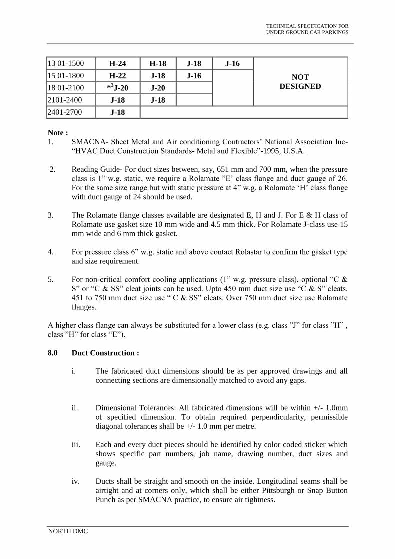
TECHNICAL SPECIFICATION FOR
UNDER GROUND CAR PARKINGS
NORTH DMC
13 01-1500 H-24 H-18 J-18 J-16
NOT
DESIGNED
15 01-1800 H-22 J-18 J-16
18 01-2100 *3J-20 J-20
2101-2400 J-18 J-18
2401-2700 J-18
Note :
1. SMACNA- Sheet Metal and Air conditioning Contractors’ National Association Inc-
“HVAC Duct Construction Standards- Metal and Flexible”-1995, U.S.A.
2. Reading Guide- For duct sizes between, say, 651 mm and 700 mm, when the pressure
class is 1” w.g. static, we require a Rolamate ”E’ class flange and duct gauge of 26.
For the same size range but with static pressure at 4” w.g. a Rolamate ‘H’ class flange
with duct gauge of 24 should be used.
3. The Rolamate flange classes available are designated E, H and J. For E & H class of
Rolamate use gasket size 10 mm wide and 4.5 mm thick. For Rolamate J-class use 15
mm wide and 6 mm thick gasket.
4. For pressure class 6” w.g. static and above contact Rolastar to confirm the gasket type
and size requirement.
5. For non-critical comfort cooling applications (1” w.g. pressure class), optional “C &
S” or “C & SS” cleat joints can be used. Upto 450 mm duct size use “C & S” cleats.
451 to 750 mm duct size use “ C & SS” cleats. Over 750 mm duct size use Rolamate
flanges.
A higher class flange can always be substituted for a lower class (e.g. class ”J” for class ”H” ,
class ”H” for class “E”).
8.0 Duct Construction :
i. The fabricated duct dimensions should be as per approved drawings and all
connecting sections are dimensionally matched to avoid any gaps.
ii. Dimensional Tolerances: All fabricated dimensions will be within +/- 1.0mm
of specified dimension. To obtain required perpendicularity, permissible
diagonal tolerances shall be +/- 1.0 mm per metre.
iii. Each and every duct pieces should be identified by color coded sticker which
shows specific part numbers, job name, drawing number, duct sizes and
gauge.
iv. Ducts shall be straight and smooth on the inside. Longitudinal seams shall be
airtight and at corners only, which shall be either Pittsburgh or Snap Button
Punch as per SMACNA practice, to ensure air tightness.

TECHNICAL SPECIFICATION FOR
UNDER GROUND CAR PARKINGS
NORTH DMC
v. Changes in dimensions and shape of ducts shall be gradual (between 1:4 and
1:7). Turning vanes or air splitters shall be installed in all bends and duct
collars designed to permit the air to make the turn without appreciable
turbulence.
vi. Plenums shall be shop/factory fabricated panel type and assembled at site.
vii. The deflection of transverse joints should be within specified limit for
rectangular duct deflection as given in SMACNA. Page no. 7.6.
viii. Reinforcement of ducts shall be achieved by either cross breaking or straight
beading depending on length of ducts.
ix. Duct Sizes- 19” (483 mm) wide and larger which have more than 10 sq.ft. of
unbraced panel shall be beaded or cross broken unless ducts will have
insulation covering or acoustical lined. This requirement is applicable to 20 g
(1.00 mm) or less and 3” W.G. (750 Pa) pressure or less. Ducts for 4” W.G.
(1000 Pa) or more do not require beads or cross-breaks.”
9.0 Support System :
A completely galvanized system consisting of fully threaded rods, slotted angles or
double-L bottom brackets (made out of 3.0 mm M.S. sheet) nuts, washers and anchor
bolts as supplied by Rolastar or generally conforming to SMACNA standards should
be used.
Supporting Schedule for Horizotal Duct
Sr.
No.
Maximum Duct
Size(mm)
Hanger Rod
Diameter Interval(mm)
1 Upto - 700 6 mm 2400
2 701 - 1200 8 mm 2400
3 1201 - 2000 10 mm 2400
4 Above 2000 12 mm 2400
i. As an alternative, slotted galvanized brackets attached to the top two bolts of
the Rolamate system may also be used as appropriate for the site condition.
ii. To provide the required thermal brake effect, Neoprene or equivalent material
of suitable thickness shall be used between duct supports and duct profiles in
all supply air ducts not enclosed by return air plenums.

TECHNICAL SPECIFICATION FOR
UNDER GROUND CAR PARKINGS
NORTH DMC
10.0 Installation :
10.1 Tools and Tackles for Site Work :
The duct installation shall conform to SMACNA norms. For duct assembly and
installation the use of suitable tools and tackles should be used to give the required
duct quality and speed of installation including (but not restricted to) :
i) Electric Pittsburgh Seamier–used for closing Pittsburgh joints.
ii) Electric Slitting shear–to make cut-outs.
iii) Drilling machine with drill bits – for drilling holes in sheet metal work.
iv) Hammer drill machine with drill bits – for drilling holes in building structures
for anchors.
v) Hoisting system – for lifting the duct assembly upto mounting heights.
10.2 Installation Practice :
i. All ducts shall be installed as per tender drawings and in strict accordance
with approved shop drawings to be prepared by the Contractor.
ii. The Contractor shall provide and neatly erect all sheet metal work as may be
required to carry out the intent of these specifications and drawings. The work
shall meet with the approval of Owner’s site representative in all its parts and
details.
iii. All necessary allowances and provisions shall be made by the Contractor for
beams, pipes, or other obstructions in the building whether or not the same are
shown on the drawings. Where there is interference/fouling with other beams,
structural work, plumbing and conduits, the ducts shall be suitably modified as
per actual site conditions.
iv. Ducting over false ceilings shall be supported from the slab above, or from
beams. In no case shall any duct be supported from false ceilings hangers or
be permitted to rest on false ceiling. All metal work in dead or furred down
spaces shall be erected in time to occasion no delay to other contractor’s work
in the building.
v. Where ducts pass through brick or masonry openings, it shall be provided with
25mm thick appropriate insulation around the duct and totally covered with
fire barrier mortar for complete sealing.

TECHNICAL SPECIFICATION FOR
UNDER GROUND CAR PARKINGS
NORTH DMC
vi. All ducts shall be totally free from vibration under all conditions of operation.
Whenever ductwork is connected to fans, air handling units or blower coil
units that may cause vibration in the ducts, ducts shall be provided with a
flexible connection, located at the unit discharge.
11.0 Documentation and Measurement for Ducting :
All ducts fabricated and installed should be accompanied and supported by following
documentation:
i. For each drawing, all supply of ductwork must be accompanied by computer-
generated detailed bill of materials indicating all relevant duct sizes,
dimensions and quantities. In addition, summary sheets are also to be provided
showing duct area by gauge and duct size range as applicable.
ii. Measurement sheet covering each fabricated duct piece showing dimensions
and external surface area along with summary of external surface area of duct
gauge-wise.
iii. All duct pieces to have a part number, which should correspond to the serial
number, assigned to it in the measurement sheet. The above system will ensure
speedy and proper site measurement, verification and approvals.
12.0 Testing :
After duct installation, a part of duct section (approximately 5 % of total ductwork)
may be selected at random and tested for leakage. The procedure for leak testing
should be followed as per SMACNA- “HVAC Air Duct Leakage Test Manual” (First
Edition)
13.0 Fire and Smoke Dampers :
i. All Fresh air ducts shall be provided with Motor operated Fire and Smoke
damper. Fire dampers, shall be provided with approved make, and shall have
fire rating of at least 90 minutes as per UL555/1995 tested by CBRI.
ii. The dampers frame and the blades shall be fabricated out of 16 gauge G.I.
sheets. The damper blades on both ends shall be pivoted using chrome-plated
spindles in self-lubricating bronze bushes. Stop sealed shall be provided on top
and bottom of the damper housing. To prevent smoke leakage, side seals shall
be provided.
iii. The normal position the damper shall be held in open position with the help of
a stainless steel spring through a thermal link. The thermal link will be UL
stamped. This link will be set to operate at 165 deg. F.
iv. Smoke & fire damper shall have similar construction as above. However,
these dampers will be motorized types having electric actuator, actuated by

TECHNICAL SPECIFICATION FOR
UNDER GROUND CAR PARKINGS
NORTH DMC
smoke sensor and electronic heat detector factory set at 165 deg. F. The
dampers shall be provided with spring return system to ensure damper closing
incase of power failure and open the same in case of power being restored.
v. Fire and smoke dampers shall be mounted in fire rated wall with a duct sleeve
of 400 mm/500 mm long depending upon the wall thickness. The sleeve shall
be factory fitted on fire damper. The joints at sleeve end shall be slip on type.
Minimum thickness of GI sheet shall be 18 Gauge.
vi. Each damper shall be provided with its own control panel, mounted on the
wall suitable for 220V AC supply. This control panel shall be suitable for
spring return actuator and shall have at least the following features :
Potential free contacts for AHU fan ON / OFF and remote alarm
indication.
Accept signal from external smoke/ fire detection system for tripping
the electrical actuator.
Test and reset facility.
Power supply ON.
Alarm.
Damper open and close position.
vii. Actuator shall be mounted on the sleeve by the damper supplier in his shop
shall furnish test certificate for satisfactory operation of each motor operated
damper in conjunction with its control panel. Control panel shall be wall
mounted type.
viii. It shall be HVAC Contractor’s responsibility to co-ordinate with the Fire
Alarm System Contractor for correctly hooking up the motor operated damper
to fire detection / fire management system. All necessary material for hooking
up shall be supplied and installed by HVAC Contractor under close co-
ordination with the fire protection system contractor.
ix. HVAC Contractor shall demonstration the testing of all dampers and its
control panel after necessary hook up with the fire protection / fire
management system is carried out by energizing all the smoke detection with
the help of smoke.
x. HVAC Contractor shall provide fire retardant cables wherever required for
satisfactory operation and control of the damper.
xi. HVAC Contractor shall strictly follow the instruction of the damper supplier
or avail his services at the site before carrying out testing at site.

TECHNICAL SPECIFICATION FOR
UNDER GROUND CAR PARKINGS
NORTH DMC
xii. Fire / Smoke damper shall be provide with factory fitted sleeves however,
access doors shall be provided in the ducts within AHU room in accordance
with the manufacturer’s recommendation.
xiii. The Contractor shall also furnish to the owner, the necessary additional spare
actuators and temperature sensor ( a minimum of 5% of the total number
installed ) at the time of commissioning of the installation.
14.0 Fresh and Exhaust air Registers :
a. Fresh and Exhaust air Grille :
Supply and return air registers shall be made of high quality extruded
aluminium profiled construction with the advantages of corrosion resistance
and rigidity. Extruded aluminium registers shall be either anodized or powder
coated and 20 to 30 mm wide flanges on four sides as specified in schedule of
quantities.
Supply and return air registers shall have two sets parallel aerofoil blades with
one set mounted horizontally on the front and other set vertically at the rear.
Frame shall be separated from aerofoil deflection blades by nylon bushings to
ensures quiet, smooth and rattle free operation.
Deflection blades shall be designed in such a manner that it can be adjusted
manually and individually, to provide air deflection in both horizontal and
vertical planes.
Core shall be suitable for clip fixing type, permitting its removal without
disturbing the flanges.
Maximum effective pressure areas should be achieved when the blades are
positioned at 0° position.
The registers shall be suitable for fixing arrangement having concealed
screws.
Foam gasket shall be sealed around the back of the frame to avoid air leakage.
Supply air registers shall be provided with key operated opposed blade all
extruded aluminum construction volume control damper in black anodized
finish.
All supply and return air registers sizes and color shall be as per approved
shop drawings.

TECHNICAL SPECIFICATION FOR
UNDER GROUND CAR PARKINGS
NORTH DMC
15.0 Access Doors with Removable Door Frame :-
Access door shall be installed in the duct wherever splitter damper, fire damper or
supply air plenum is installed. Duct access doors and frame shall be fabricated from
22 gauge galvanized steel sheet and structure shall be designed to withstand high
pressure differences. Frame for access door shall be provided with 3 mm thick
neoprene gasket all around to avoid air leakage. Door panel shall be internally
insulated with approved insulation material and thickness wherever required.
Minimum size of the access door shall not be less then 200mm x 200mm. All access
door shall be provided with 4 no zinc plated cam locks and chromium plated handle
for easy removal and fixing.
16.0 Fresh Air Intake Louvers :
a. Fresh air intake louvers wherever required as per shop drawing will be made
of extruded aluminum construction duly anodized or powder coated. Bird /
insects screen will be provided with the intake louvers.
b. The lowest louver of the assembly shall extended out slightly to facilities
disposal of rainwater without falling on door / wall on which it is mounted.
c. Wherever specified, the intake louvers & frame shall be provided with factory
fitted all aluminum construction volume control dampers in black anodized
finish.
17.0 Flexible Connections :
All duct work connections to equipment such as indoor unit shall be with flexible
connections, to prevent the transmittance of vibrations from the equipment through
the ductwork system. Connections shall not exceed 200mm in length and shall be non
porous insulated mould proof type double canvas. Connections shall be secured to
make a suitable airtight seal with the ductwork and equipments.
18.0 Flexible Duct Works:
General :
a. Flexible duct shall be used for Fresh air intake only. It shall be non-
combustible, flexible metal duct, constructed of corrugated aluminum
with water tight lock seams and shall be compressed lengths with one
crimped end and one plain end.
b. Operating pressure: 6” w. g. pos./neg.
c. Maximum velocity: 500 FPM.
d. Temperature Range: -73 deg. C to 221 deg. C.

TECHNICAL SPECIFICATION FOR
UNDER GROUND CAR PARKINGS
NORTH DMC
19.0 Testing and Balancing :
a. After the installation of the entire air distribution system is completed in all
respects, all ducts shall be tested for air leaks by visual inspection.
b. The entire air distribution system shall be balanced using an approved
anemometer. Measured air quantities at fan discharge and at various outlets
shall be identical to or less than 5% in excess of those specified and quoted.
Branch duct adjustments shall be permanently marked after air balancing is
completed so that these shall be restored to their correct position if disturbed at
any time. Complete air balance report shall be submitted for scrutiny and
approval, and four copies of the approved air balancing report shall be
forwarded with completion documents.

TECHNICAL SPECIFICATION FOR
UNDER GROUND CAR PARKINGS
NORTH DMC
FIRE FIGHTING SYSTEM INCLUDING WATER PUMPS
.
1 WATER SUPPLY PUMPS
1.1 WATER TRANSFER PUMPS
Water transfer pumps shall be multistage, vertical stainless steel pumps, having
stainless steel casing, stainless steel pump foot and diffushers, stainless impeller,
stainless steel shaft, ceramic bearings, tungsten carbide shaft protection bushes and
mechanical seal driven by 1.0 kw (Approx), 2900 RPM, 220 Volts, 50 Cycles, AC 3
–phase TEFC vertical flange motor. Each pump shall be capable of operating with in
a performance pressure characteristics range sufficient below and above the required
working pressure.
Pumps and motors shall be mounted on a common MS structural base plate.
Each pump shall be provides with a totally enclosed fan cooled induction motor of
H.P and R.P.M specified in schedule of quantities.
Each pumping set shall be provides with a Gun Metal “Bourden” type pressure
gauge with gunmetal isolation cock and connecting piping.
Appropriate vibration eliminating pads shall be provides with each pump.
The pump set shall be provided with gunmetal gate valve of appropriate sizes on
delivery. a non-return valve of appropriate size and a pressure gauge with cock shall
be provided on the delivery line.
Suction and delivery lines of the pumps shall be provided with double flanged
reinforced Neoprene flexible pipe connectors. Connectors shall be suitable for a
working pressure of each pump as specified in Schedule of Quantities.

TECHNICAL SPECIFICATION FOR
UNDER GROUND CAR PARKINGS
NORTH DMC
1.2 SUMP PUMPS
Pumps shall be submersible type as indicated in data sheet.
Pump shall be integral with submersible motor on a common shaft. The pumps shall
have 2900 rpm synchronous speed unless stated otherwise in the data sheets.
The pump set shall be installed in vertical position in sumps with level controller
cum operated float switches.
Pump casings shall be aluminum and impellers of SS. All pumps shall have
combination ball and roller bearings and shaft seals should be mechanical. Motor
shall be submersible and shall be rated for minimum hp specified or the BHP
absorbed in the operating range of the pump.
1.3 LEVEL CONTROLLER
Contractor shall provide and install low voltage transistorised level controllers as
specified in Schedule of Quantities. Each level controller shall be provided with
required number of PVC sheathed stainless steel probes with necessary wiring and
conducting.
1.4 WATER TRANSFER PUMPS
To cut off water transfer pumps on low water level in water tank and high water
level in overhead water tank and start sump on low water level in overhead water
tank.
1.5 INSTALLATION AND TESTING
All pumps shall be laid out generally in accordance with the shop drawings
(submitted by contractor and approved by engineer-in-charge / consultant /
architect) achieving economy of space and piping.

TECHNICAL SPECIFICATION FOR
UNDER GROUND CAR PARKINGS
NORTH DMC
All pumps shall be tested for the rated performance in the presence of the employer's
representative and got approved.
1.6 Mode of measurement
Measurement for pumps shall be in the units as per item description.
1.7 CATALOGUES & MANUAL
The Contractor shall furnish the operation & maintenance manual/ technical
literatures in duplicate to engineer-in-charge.
FIRE HYDRANT SYSTEM
2. Scope of work
The scope of work shall cover supply, fabrication, installation, testing and
commissioning of the fire hydrant system covering the following but not limited to:
Fire Hydrant pumps, electric and diesel driven as shown in the equipment schedule,
drawings and as required.
Jockey pump, electric driven as shown in the equipment schedule, drawings and as
required.
Engine Control Panel.
Hydrant mains, external ring and yard hydrants.
Wet risers in the building as specified and shown on drawings.
Landing valves, hose reels, hose cabinets etc.
Fire brigade breaching, siamese connections and connections to pumps and
appliances.
The contractor shall get the Fire Fighting System approved by the Chief Fire Officer
of Delhi Fire Service.

TECHNICAL SPECIFICATION FOR
UNDER GROUND CAR PARKINGS
NORTH DMC
2.1 Standards
The fire hydrant installation shall conform to and meet with the requirements set out
by the following:
As relevant IS Code of practice for the safety of buildings (General) fire fighting
equipment and its maintenance.
As relevant IS Code of practice for installation of internal fire hydrant in multi-
storeyed building.
Compliance with the local fire brigade and the fire enforcing authorities as
specifically laid down by them.
2.2 Fire pump
The fire pump shall be single stage / double stage suction centrifugal type with split
casing type and direct driven by electric motor or diesel engine as specified. The
pump rating and performance shall conform to the equipment schedule and meet the
TAC duty requirements.
Pump casing shall be of close grained cast iron with bronze impeller. The shaft
sleeve shall be brass or SS 304 and the trim shall be brass or bronze.
Pump shall be capable of delivering 150% of the rated capacity at 65% of the rated
head and the no-delivery head shall be not more than 140% (150% in case of end
suction type) of the rated delivery head. The pump casing shall withstand 1.5 times
the no-delivery pressure or 2 times of the duty pressure whichever is higher.
The pump shall be either electrically driven or diesel driven with direct flexible
coupling.
The electric drive motor shall be squirrel cage induction conforming to IS 325 -
1978 and rated for continuous duty (S1). Motor shall have not less than class F
insulation and minimum enclosure of IP22. The starter shall be air cooled fully
automatic star delta or auto transformer type. Starters shall conform to IS 8544 and
rated for AC-3 duty conditions.
Drive rating shall be based on the largest of the following:
a) Rated pump discharge at rated head

TECHNICAL SPECIFICATION FOR
UNDER GROUND CAR PARKINGS
NORTH DMC
b) 150% of rated discharge @ 65% of rated head
c) Maximum power absorbed by the pump in its operating range i.e. no-delivery to
free discharge.
The diesel engine shall be naturally aspirated (non-turbocharged) and electrically
started. The engine shall be complete with starting batteries full-wave selenium
rectifier charger, isolator, leads, mounting frame etc. Engine rating shall be same as
for the electric motor. The detailed specifications of the engine are at Clause no 6.0.
2.3 Accessories
The Fire Pumps shall be complete with the following accessories:
a) Suction and discharge eccentric reducers
b) Pump coupling guard
c) Common base frame, fabricated mild steel or cast iron.
Each pump shall have independent set of pressure switches. The pressure switch shall
be snap action SP DT switch rated 10A @ 220 V operated through a stainless steel
diaphragm. The switch shall have a pointer for manual adjustment of set point, and all
electrical connections shall be terminated in a screwed terminal connector. The entire
unit shall be encased in a cold drawn steel (heavy gauge) enclosure. The diaphragm
shall be designed for a maximum operating pressure of the system. Each pressure
switch shall be provided with a pressure gauge in parallel as shown on the drawings
and all gauges and pressure switches shall be mounted in an instrument panel with
necessary control piping and drainage facility.
2.4 System operation and control panels
The fire pump shall be started automatically on loss of pressure and the operation
sequence of the booster and fire pumps shall be as follows:
a) Jockey Pump shall start when the system pressure drops by 0.35 kg/cm2 and
stop when the system pressure is re-established.
b) The Fire Pump shall start when the system pressure drops by 1.0 kg/cm2 and
shall continue to run till manually switched off.
TECHNICAL SPECIFICATION FOR
UNDER GROUND CAR PARKINGS
NORTH DMC
c) Jockey and fire pump starting shall be indicated on the panel with a red
indication lamp.
The motor starters (direct on line or star-delta) shall consist of electrically actuated
contactors. The starter shall be complete with ON-OFF push buttons, timers and
auxiliary contacts and shall be fully automatic. There shall be an indicating lamp
with each of the pumps and an ammeter and selector switch with the fire pumps.
Fire pump starting shall be annunciated through an electric siren.
The starter along with isolator shall be housed in a 14 SWG MS box duly rust
inhibited through a process of degreasing and phosphating.
All cabling to and from the pumps to starter and control switch shall be carried out
through armoured PVC cables of approved makes. Cables shall be laid in
accordance with section "M V CABLING". The pump motors and panels shall be
double earthed in accordance with IS 3043-1966 or as shown on drawings and as
approved.
2.5 Diesel Engine
The diesel engine shall be of multi cylinder type four stroke cycle with mechanical
(airless) Injection, cold starting type.
The engine shall be designed with regard to ease of maintenance, repair, cleaning
and inspection. This will also provide interchangeability of parts.
All parts susceptible to temperature changes shall have tolerance for expansion
and contraction without resulting in leakage, misalignment of parts or injury to
parts.
The engine shall be capable of both automatic and manual start. Generally the
engine shall start automatically, but in case of the auto-start system failure the
engine shall be capable of manual start. Engine shall be able to start without any
preliminary heating of combustion chamber; cranking mechanism shall also be
provided. All controls / mechanisms which have to be operated in the starting
process, shall be within easy reach of the operator. A day oil tank constructed

TECHNICAL SPECIFICATION FOR
UNDER GROUND CAR PARKINGS
NORTH DMC
from minimum 1.6 mm thick sheet MS sheet of 200 litres capacity shall be
provided as per Engine manufacturer's guide line.
A high torque D.C. motor charged by battery shall initiate automatic start of diesel
engine. The battery shall hold adequate retainable charge to provide the starting of
the diesel engine. Starting power will be supplied from storage batteries. The
battery capacity shall be adequate for ten consecutive starts without recharging
with a cold engine under full compression. Battery shall be lead acid type of 12 V,
180 Ah capacity.
The battery banks shall be used for no other purpose other than starting of the
engine and shall be fully charged at all times with provision for trickle & boost
chargers. After start of the engine the charger shall be disconnected, the battery
being fed from the engine dynamo.
The engine shall have a speed control device (Governor) which will control the
speed under all conditions of load. The governor shall be suitable for operation
without external power supply.
The Engine shall an adjustable governor to regulate engine speed within a range
of 10 % between shut-off and maximum load conditions of the pumps. The
governor shall be set to maintain rated pump speed at maximum pump load.
The Governor shall have an over speed shutdown device to shutdown the engine
at a speed approximately 20 % above rated engine speed with manual reset, so
that the automatic engine controller will indicate an over speed signal until the
device is manually reset to normal operating position.
The Diesel Engine shall cooled by a Heat Exchanger and the Contractor shall be
make arrangement for continuous supply of such water.
The engine shall be mounts on a base plate of fabricated steel construction.
Adequate access shall be provides to the big end and main bearings, camshaft and
governor drives, water jackets etc.
The engine shall have a base plate made from M S sections. There shall be
reasonable space at the big end, camshaft, water jackets, governor drives and main
bearings.

TECHNICAL SPECIFICATION FOR
UNDER GROUND CAR PARKINGS
NORTH DMC
The engine shall be provides with intake and discharge ductwork, inlet filter and
silencer, outlet muffler, expansion joints, dampers etc. as necessary for efficient
operation. Intake air shall be taken from inside the building in which the engine is
located, but the exhaust shall be discharged into the air.
The diesel engine shall be provides with adequate instrumentation. The gauges
etc. as required are provides for in the Engine Panel.
2.6 Diesel Pump Panel:
The Panel shall consist of the following:
Engine Starting System:
It shall be provided with a Lead Acid of minimum 180 Ah capacity to provide
adeqaute throttle for starting.
Engine Instruments and Control Panel:
It shall be complete with required connections to set and comprising:
Inlet and out let water temperature gauge (dial type)
Lubrication oil pressure gauge.
Lubrication oil Temperature gauge.
Automatic Start Stop Device.
The Engine shall be provided with Manual Start / Stop Switch by means of Push
Buttons.
Start Stop and Failure Control Device.
Start key for manual starting.
Stop Push Button for manual stopping of engine.
Starting failure indication by lamp and Horn Unit.
Engine temperature control with failure indication by red lamp.
Engine temperature very high indication by audio alarm and automatic stopping of
engine.
Engine set in operation indication by green lamp.

TECHNICAL SPECIFICATION FOR
UNDER GROUND CAR PARKINGS
NORTH DMC
Mains supply available indicated by yellow lamp.
Push Button for Audio Alarm reset.
Push Button Failure Indication by lamps.
The Panel shall also have an Auto / Manual / Test / Off Selector Switch.
2.7 Fire hydrants and hose reels
Hydrants shall be provides internally and externally as shown on the drawings.
Internal hydrants shall be provides at each landing of and escape staircase and
additionally depending on the floor area as shown on drawings. Landing valve shall
be single headed gunmetal valve with 63 mm dia outlets and 80mm inlet
conforming to IS 5290-1969. Landing valve shall have flanged inlet and
instantaneous type outlets and mounted at 1.0m above the floor level. Instantaneous
outlets for the hydrants shall be of standard pattern approved and suitable for 63mm
dia fire brigade hoses. Wherever necessary, pressure reducing orifices plate and
shall be provided so as to limit the pressure to 3.5 kg/sqcm or any other rating as
required by the Local Fire Authority.
Each landing valve shall have a hose reel cabinet as shown on drawings.
a) Landing valve with single 63 mm dia outlet and 80 mm dia inlet.
b) First-aid hose reel with 30 m long 25 mm dia high pressure double braided
rubber hose ( IS:444 marked ) with 25 m dia Ball Valve.
c) 2 Nos. 15.0 Meter long 63 mm dia Reinforced Rubber Lined (RRL) hoses with
gun metal I.S. marked instantaneous couplings.
d) One gun metal branch pipe.
The First Aid Hose shall conform to IS 884-1969 and be wound on a heavy duty
circular hose reel with a bracket. The hose shall be permanently connected on one
end to the Wet Riser through a 25m Ball Valve with necessary hose adapter and a
gun metal nozzle at the other end.
Hoses shall be in two lengths of 15.0 m each, of RRL type with instantaneous
couplings, neatly rolled into bundles and held in position with steel brackets. Hoses
shall be tested and certified by the manufacturer, to withstand an internal water

TECHNICAL SPECIFICATION FOR
UNDER GROUND CAR PARKINGS
NORTH DMC
pressure of not less than 35 kg/sqcm without bursting. The hose shall also withstand
a working pressure of 7 kg/sqcm without leakage.
The hose cabinet shall be fabricated from 2mm mild steel sheet duly rust inhibited
through a process of degreasing and phosphating. The cabinet shall have double flap
hinged doors with 4mm clear glass and shall have necessary openings for riser main
and brackets for all internals. The cabinet shall receive two coats of red oxide
primer both inside and outside before two after coats of final paint of approved
colour shade.
External hydrants shall be as per IS:5490 with hand wheel control and a 80 mm dia
pipe stand post. Hydrants shall be located at least 2m away from and within 15m
from the building wall.
Each hydrant shall be provided with a hose cabinet containing 2x15m 63 dia RRL
hoses with couplings. The cabinet shall contain a branch pipe and nozzle. The
cabinet shall be 900 x 600 x 400 fabricated out of 2 m mild steel sheet duly rust
inhibited through a process of degreasing, phosphating etc. The cabinet shall receive
two coats of red oxide primer, inside and outside, before 2 coats of final painting of
approved shade. The cabinet shall be wall-mounted or free standing with its own
steel legs depending on the site conditions and as shown on drawings and as
approved.
The fire brigade connection shall consist of two / three/four headed as specified in
BOQ 63mm dia gun metal outlets with built-in check valve and drain plugs
connected to a 150mm dia outlet connection to the water reservoir or to the hydrant
main. The fire brigade collecting head shall conform to IS 904-1965.
2.8 Test & commissioning
The Jockey & fire pump starting and stopping shall be tested by opening the test
valve and record the following and the valves should be as furnished below:
1) Jockey pump start/stop
System pressure at start-up : 4.5 kg/sqcm
System pressure at stop : 5.6 kg/sqcm
Time elapsed from start to stop : 2 Seconds

TECHNICAL SPECIFICATION FOR
UNDER GROUND CAR PARKINGS
NORTH DMC
2) Hydrant Pump start
System pressure at start-up : 4.0 kg/sqcm
3) Diesel Engine Pump start : 3.0 Kg/sqcm
Maintained system pressure while discharging the landing valve at the highest
point.
a) Pump end : 5.6 kg/sqcm
b) Highest outlet : 3.5 kg/sqcm
c) Intermediate points : 4.5 kg/sqcm
2.8 Mode of measurement
Hydrant pump with mounting frame, excluding concrete foundation shall be
measured per unit.
Jockey pump same as hydrant pump.
Instrument panel with pressure gauges, pressure switches, control piping etc. shall
be measured as one unit.
Control cabling from pressure gauge panel to the respective starters shall be
measured in running meter and paid at unit rates.
2.9 Piping
External
All External pipes shall be, unless otherwise specified, heavy quality mild steel
tubes to IS 1239 using wrought GI steel heavy duty screwed fittings. Flanges shall
be provided to mate with valves and other equipment and shall conform to IS 6392.
Flanges shall be screwed type. Flanges shall be rated for 2.0 N/sqmm.
Black mild steel pipes, when laid underground, shall be protected against corrosion
by two coats of hot bitumen and 2mm thick wrapping of pypkote. Fittings shall be
weld able wrought iron, suitable for butt welding and 10% of the welded joints shall
be radio graphically tested and found in order. The welded joints shall be random
selected for testing in consultation with the Engineer-in-charge. All flanges shall be

TECHNICAL SPECIFICATION FOR
UNDER GROUND CAR PARKINGS
NORTH DMC
slip-on welded type to IS 6392 with a 3mm fibre-reinforced teflon gasket and rated
for 2.0 N/sq. mm.
Underground mains shall be laid not less than 750 mm below the ground level
and shall be at least 2m away from the building face and supported on concrete
pedestals at every 3.5m and held on with galvanised iron clamps. Concrete thrust
anchors shall be provided at all bends and tees as shown on drawing and as directed.
All excavation for pipe laying shall be carried out with sufficient width for making
proper joints. Backfilling shall be done only after the piping is hydro-statically
pressure tested. Piping shall be constantly kept clean till tested.
All valves shall be housed in brick masonry chambers over 150mm cement concrete
(1:3:6) foundation. The brick walls of the chamber shall be plastered inside and
outside with 20mm cement sand plaster 1:4 with a floating coat of neat cement.
Chambers shall be 650 x 650 mm clear for depths upto 1200 mm and 1000 x 1000
mm for depths beyond. Each chamber shall have a cast iron surface box approved
by the Engineer in-charge.
Piping laid above ground shall be supported on cement concrete (1:2:4) pedestals
raising the bottom of the pipe at least 150mm over the ground level and held to the
pedestals with galvanised clamps. Pedestals shall be made at 3.0m centre to centre
and as shown on drawings. Cement concrete 1:2:4 thrust anchors shall be provided
at all tee-off points and change of direction as shown on drawings and as required.
Pipes laid on walls and ceiling shall have galvanised steel brackets.
2.10 Internal
All internal pipes shall be, unless otherwise specified, heavy quality mild steel tubes
to IS 1239 using wrought steel heavy duty screwed fittings. Flanges shall be
provided to mate with valves and other equipment and shall conform to IS 6392.
Flanges shall be screwed type. Flanges shall be rated for 2.0 N/sqmm.
Valves shall be suitable for external piping.
All pipes shall be of approved make and best quality without rust marks. Pipes and
fittings shall be fixed in a manner as to provide easy accessibility for repair,

TECHNICAL SPECIFICATION FOR
UNDER GROUND CAR PARKINGS
NORTH DMC
maintenance and shall not cause obstruction in shafts, passages etc. Pipes and
fittings shall be fixed truly vertical, horizontal or in slopes as required in a neat
workmanship manner. Pipes shall be securely fixed to walls and ceilings by suitable
supports at intervals specified. Only approved type of anchor fasteners shall be used
for RCC ceiling and walls.
All pipes shall be adequately supported from ceiling or walls through structural
supports fabricated from mild steel structural e.g. rods, channels, angels and flats
generally as shown on drawings. Fasteners shall be shear type anchor fasteners in
concrete walls and ceilings and wrought steel spikes of at least 75mm long in brick
walls. All pipes supports shall be painted with 1 coats of red oxide primer and two
coats of black enamel paint.
All low point loops in the piping shall be provided with 25mm Ball Valves with
rising spindle for draining the system. All valves shall have screwed brass caps.
Likewise 25mm gun metal air vents shall be provided at all high point loops to
prevent air-locking.
All piping shall have flanged joints at about 25m intervals to facilitate easy
maintenance.
2.11 Pipe Jointing
All pipes shall be provided with threaded joints up to 50mm diameter and welded
joints for pipe above 50mm diameters. Hold tite shall be used for sealing.
All welded joints shall be tested by radiography test.
Joints between CI and GI pipes shall be made by providing a suitable flanged tail
or socket piece and MS flange on the GI pipe. Flanges shall have appropriate
number of holes and shall be fastened with nuts, bolts and 1.5mm thick
compressed asbestos gasket.
TECHNICAL SPECIFICATION FOR
UNDER GROUND CAR PARKINGS
NORTH DMC
2.12 Valves and other accessories
Gate Valves
Sluice / Gate valves shall be used for isolation of flow in pipe lines For sizes upto
65 mm, gate valves shall be outside screw rising spindle type and shall be as per
IS: 778 Class-I and Class-II, as applicable. For sizes 80 mm to 300 mm, gate valve
shall be as per IS: 780, PN=1.0 and shall be of inside screw and non rising type and
cast iron double flanged.
Gate valves shall be provided with a hand wheel, draining arrangement of seat valve
and locking facility (as required). Gate valves shall have back setting bush to
facilitate gland renewal during full open condition.
The Body, bonnet, Stuffing Box, cap and hand wheel shall be of cast iron to
IS:210/70, grade FG 200 / 260. The non rising spindle shall be of solid forged high
tensile brass or carbon steel to AISI 304 construction. The Body seating and wedge
ring shall be of solid leaded gun metal. The Bonnet gasket shall be of high quality
rubber.
The Valve shall be PN 1.0 rated but shall withstand tests of upto 20 kg / cm2. The
ends shall be flanged. The batch number of the valve shall be punched on the top of
the flange. The spindle shall be removable type, and shall be easily rotated.
2.13 Pressure Switch
The Pressure switches shall be employed for starting and shutting down operation
of pumps automatically, dictated by line pressure. The Pressure Switch shall be
diaphragm type. It shall be suitable for line pressures upto 15 kg / cm2. The scale
range for cut in and cut out shall be from 0 to 10 kg / cm2.
The Switch shall be suitable for consistent and repeated operations without change
in values. It shall be provided with IP:66 water and environment protection.
The enclosure shall be of aluminium and pressure element and wetted parts shall
be of stainless steel. The switch shall be snap acting type with 1 number
N O / N C contact.
TECHNICAL SPECIFICATION FOR
UNDER GROUND CAR PARKINGS
NORTH DMC
2.14 Air Vessel
Air vessel shall be fabricated from 6 mm thick, 300mm x 1000mm MS plate
suitable for 7kg/cm2 working pressure complete with air release valve, safety
valve, pressure gauge etc. as required. The air vessel shall be continuous welded
construction and painted with two coats of Postal red enamel outside over a coat
of primer and epoxy paint inside.
2.15 Pressure Vessel
The Pressure Vessel shall be provided to compensate for slight loss of pressure in
the system and to provide an air cushion for counter acting pressure surges
whenever the pumping set comes into operation. It shall be normally partly full of
water, the remaining being filled with air which will be under compression when
the system is in normal operation.
Pressure vessel shall be fabricated from 8-10 mm thick MS plate with dished ends
and suitable supporting legs. It shall be provided with a 50 mm dia flanged
connections from pump, one 25 mm drain with ball valve, one water level gauge
and 25 mm sockets for pressure switches. The pressure vessel shall be
hydraulically tested as required.
The Pressure Vessel shall be for Hydrant Systems. The Pressure Switches shall be
mounted on the drain end of each Vessel. The Vessel shall also be provided with
an air release valve mounted at the top.
2.16 Pressure Gauge
The Pressure Gauge shall be constructed of die cast aluminium and stove enameled.
It shall be weather proof with an IP 55 enclosure. It shall be a stainless steel
Bourden tube type Pressure Gauge with a scale range from 0 to 16 Kg / CM2 and
shall be constructed as per IS: 3624. Each Pressure Gauge shall have a siphon tube
connection. The Shut off arrangement shall be by Ball Valve.

TECHNICAL SPECIFICATION FOR
UNDER GROUND CAR PARKINGS
NORTH DMC
2.17 Ball Valve
The Ball Valve shall be made from die cast brass and tested to 14 Kg/cm2
pressure.
The valve shall be internally threaded to receive pipe connections.
The Ball shall be made from brass and machined to perfect round shape and
subsequently chrome plated. The seat of the valve body- bonnet gasket and gland
packing shall be of Teflon.
The handle shall be of chrome plated steel with PVC jacket. The handle shall also
indicate the direction of `open' and `closed' situations. The gap between the ball
and the teflon packing shall be sealed to prevent water seeping upto 14 Kg / cm2
pressure.
The handle shall also be provided with a lug to keep the movement of the ball valve
within 90 degree. The lever shall be operated smoothly and without application of
any unnecessary force.
2.18 Non Return Valve
Non-return valves shall be cast iron spring action swing check type. An arrow mark
in the direction of flow shall be marked on the body of the valve. The valve shall
bear IS:531 certification.
The Valve shall be of cast iron body and cover. The internal flap in the direction of
water shall be of cast iron and hinged by a hinge pin of high tensile brass or
stainless steel. Cast iron parts shall be conform to IS:210 / 70, grade 200 / 260 type.
The gasket shall be of high quality rubber and flap seat ring of leaded gun metal to
BS 1400 LG 2C. At high pressure of water flow the flapper shall seat tightly to the
seat. The Valve shall be capable of handling pressure upto 15 kg / cm2.

TECHNICAL SPECIFICATION FOR
UNDER GROUND CAR PARKINGS
NORTH DMC
2.19 Butterfly Valve
The Butterfly Valve shall be suitable for waterworks and tested to minimum of 16
kg / sq cm pressure. The Valves shall fulfil the requirements of AWWA (American
Water Works Association) C 504, API 609 and MSS-SP-67.
The body shall be of cast iron to IS:210 in circular shape and of high strength to
take the minimum water pressure of 10 kg / cm2. The disc shall be heavy duty cast
iron with anti corrosive epoxy or nickel coating.
The valve seat shall be of high grade elastomer or nitrile rubber. The Valve in
closed position shall have complete contact between the seat and the disc
throughout the perimeter. The elastomer rubber shall have a long life and shall not
give away on continuous applied water pressure. The shaft shall be of EN 8 grade
carbon steel.
The Valve shall be fitted between two flanges on either side of pipe flanges. The
Valve edge rubber shall be projected outside such that they are wedged within the
pipe flanges to prevent leakage.
The Valves shall be supplied with manual gear operated opening / closing system
by lever.
2.20 Pipe supports
All pipes whether horizontal or vertical shall be suitably supported using galvanized
mild steel clamps/clevis hanger manufactured by M/s Hitech Support (India) Pvt
Ltd or equivalent product of good quality as approved by engineer in-charge.
2.21 Vertical Pipes
The pipes running vertical shaft shall be supported by galvanised mild steel rigid
clamps fixed to wall with anchor bolts and studs.
When the horizontal distance between the centre line of two adjacent pipes is less
than 300 mm a powder coated HITECH/or equivalent rail shall be fixed to wall the
pipes independently clamped to the rail with `U' bolt clamps.
TECHNICAL SPECIFICATION FOR
UNDER GROUND CAR PARKINGS
NORTH DMC
2.22 Horizontal Pipes
Pipes running horizontal shall be supported from structural beam/slab by using
appropriate galvanised m.s. pipe clevis hangers.
The spacing of supports shall be as follows:
GI Pipes/MS Pipes CI Spun Pipes
Internal Dia
(mm) Spacing (mm)
Internal dia
(mm) Spacing (mm)
15 1800 75-150 2700
20,25 2400 200-250 3000
32 2700 300 3600
40-50 3000
65-80 3600
100 4000
150 4500
Supports for horizontal piping longer than 15m in a stretch shall be provided with
swivel clamps. Otherwise, the clamps shall be universal clamps or rigid clamps as
required by the project engineer.
Fixing of clamps/rails etc.
All clamps, rails and accessories shall be fixed to the structure (beam, slab, walls
etc.) by using approved good quality anchor fasteners of appropriate size.

TECHNICAL SPECIFICATION FOR
UNDER GROUND CAR PARKINGS
NORTH DMC
2.23 Painting
All exposed piping for fire fighting shall be distinctly painted `Fire red' shade 536 to
IS:5-1978. Pipes shall first receive two coats of red oxide primer uniformly applied
and two coats of oil paint applied thereafter. All pipes supports shall be painted
black as specified for support & clamps.
2.24 Painting Schedule
All equipment and piping shall be painted in accordance with the following colour
code:
Equipment Colour Distinguishing Mark
a) Pump motors Fire Red Shade
No.536 to IS: 5 -1978
b) Internal piping "
c) Landing valves &
Hose reel cabinets "
d) External Hydrants "
e) Fire brigade connection "
f) Priming tank "
g) Air vessel "
h) Electric panels Black & Red
i) Fire Alarm Panel Black & Red
j) Repeater panel Black & Red
k) Break Glass Unit Fire Red
TECHNICAL SPECIFICATION FOR
UNDER GROUND CAR PARKINGS
NORTH DMC
l) Hooters/Speakers Fire Red
m) Sprinkler pipes Fire Red
All surfaces to be painted shall be thoroughly cleaned with wire brush to remove
completely rust and other extraneous substances. Over the cleaned surfaces one coat
of red oxide primer shall be applied completely covering the exposed surfaces.
Finishing coat of enamel paint shall be applied one day after the prime coat, after
ensuring that the paint is dry. The second coat shall be done before the installation is
handed over and after approval to do so from the Engineer-in-charge.
2.25 Testing & commissioning
All piping after installation shall be tested for a hydrostatic test pressure of 10.5
kg/sqcm or 1.5 times the working pressure (whichever is less) maintained for 24
hours. All joints and valves shall be checked for leaks and rectified and retested.
During testing all valves except drain & air valves shall be kept fully open.
2.26 Makes of materials
For makes of materials refer to list of approved makes of material.
2.27 Mode of measurement
All external piping shall be measured along the centre line of the pipe and paid per
unit length and shall include:
All pipes & fittings
Bituminous coating
All internal piping shall be measured similarly but shall include for the pipe
supports and clamps.
All valves, air valves, drain valves together with flanges or tail pieces shall be
measured per unit.
TECHNICAL SPECIFICATION FOR
UNDER GROUND CAR PARKINGS
NORTH DMC
All excavation and concrete supports and thrust blocks shall be measured as per
drawing and paid for per cum.
The cost of pipe supports described above form part of the rate quoted for piping
and no extra shall be payable on the account.
All painting shall form part of the cost of equipment piping etc. No separate
payment shall be admissible.

TECHNICAL SPECIFICATION FOR
UNDER GROUND CAR PARKINGS
NORTH DMC
SPRINKLER SYSTEM
3.0 Pendant type Sprinkler Head
Sprinkler heads shall be of quartzoid bulb type with bulb, valve assembly, yoke and
the deflector. The sprinkler shall be of approved make and type with 15 mm
nominal dia outlets.
The bulb shall be made of corrosion free material strong enough to withstand any
water pressure likely to occur in the system. The bulb shall shatter when the
temperature of the surrounding air reaches at 68o C .
The nominal bore shall be 15 mm dia and colour of liquid shall be Red / Yellow.
The Sprinkler head shall be approved by UL / FM.
3.1 Upright type Sprinkler Head
Upright sprinkler heads shall be similar to Pendent type in material construction and
performance but designed to throw water Droplets upwards in umbrella fashion, to
cool the underside of ceiling and extinguish any fire involving combustibles on the
floor below.
The Sprinkler head shall be approved by UL / FM. The nominal bore shall be 15
mm dia and the colour of liquid shall be red.
Upright Sprinkler heads shall be use in lower and upper basement parking areas and
above the false ceiling.
3.2 Side Wall type Sprinkler Head
Side wall sprinkler heads shall be similar to Pendent type in material construction
and performance but designed to throw water Droplets horizontally.
The Sprinkler head shall be approved by UL / FM. The nominal bore shall be 15
mm diameter and the colour of liquid shall be red.
TECHNICAL SPECIFICATION FOR
UNDER GROUND CAR PARKINGS
NORTH DMC
Side wall sprinkler heads shall be use in staircase landing and along the ramp.
3.3 Powder coated Sprinkler with Powder coated Twin plate Rosette.
Most areas below false ceiling shall be provided with powder coated pendant
sprinkler with twin plate sliding rosette. The sprinkler head shall be same as
Pendent type above but powder coated white. The sprinkler head shall be provided
with a double plate powder coated rosette that shall seal the gap between the false
ceiling and he sprinkler head.
The adjustment allowable shall be 12 mm. The lower part shall have flared ends that
shall fit tightly into the upper piece.
The Sprinkler head shall be approved by UL / FM. The nominal bore shall be 15
mm diameter and the colour of liquid shall be red.
3.4 Installation Control Valve for Sprinkler
The Installation Control Valve shall be double seated clapper type check valve. The
Body and cover shall be made from Cast Iron to IS:210 Grade FG 200. The seat and
seat clamp shall be made from bronze to IS: 318, LTB II grade. The sealing to the
seat shall be neoprene gasket. The hinges pin and ball shall be from stainless steel.
It shall be vertically mounted and the direction of water travel shall be indicated on
the surface. It shall be rated to 12 Kg / cm2 and tested to 25 Kg / cm
2 pressure.
A By-pass check valve shall be fitted to adjust minor and slow variations in water
pressure for balancing so as to avoid any false alarm.
The valve shall also be provided with a Test Control Box. The Box shall house a
lever to test and operate the ICV. A brass strainer shall also be provided at the point
of water supply to the Alarm gong. A Retarding Chamber shall also be provided.
The Chamber shall be able to balance the water pressure in case of water line
surges.
Each Installation Control Valve shall have two sets of Pressure Gauges with brass
ball valve type shut off.

TECHNICAL SPECIFICATION FOR
UNDER GROUND CAR PARKINGS
NORTH DMC
A Water Motor Alarm. shall also be provided. This shall be mechanically operated
by discharge of water through an impeller. The drive bearing shall be weather
resistant. A strainer shall be provided on line before the nozzle. The Gong piece
shall be constructed from bronze to IS 318, 2 TB II Grade, and base of cast iron.
The Motor Housing, Rotor and Housing Cover shall be pressure die cast aluminium.
3.5 Flow Switch
Flow switch shall have a paddle made of flexible material of the width to fit within
the pipe bore. The terminal box shall be mounted over the paddle / pipe through a
connecting socket. The Switch shall be potential free in either N O or N C position
as required. The switch shall be able to trip and make / break contact on the
operation of a single sprinkler head. The terminal box shall have connections for
wiring to the Annunciation Panel. The seat shall be of stainless steel. The Flow
Switch shall have IP:55 protection.
The Flow Switch shall work at a minimum flow rate of 100 LPM. Further, it shall
have a 'Retard' to compensate for line leakage or intermittent flows.

TECHNICAL SPECIFICATION FOR
UNDER GROUND CAR PARKINGS
NORTH DMC
PORTABLE FIRE EXTINGUISHERS & EXIT SIGNAGES
4.0 Scope
The scope of work covers the supply and installation of portable fire extinguishers.
The following types are envisaged in these specifications and provided as shown in
the schedule of portable fire extinguishers.
Dry powder extinguisher
Carbon-dioxide extinguisher
Mono ammonia phosphate extinguisher
Water expelling type.
4.1 Standards
The following standards and rules and regulations shall be applicable:
Fire protection manual of the tariff advisory committee, Fire Insurance Association
of India
IS:2176 :Portable fire extinguisher Dry power type
IS:2878 :Portable fire extinguisher carbon-dioxide type
Local Fire Brigade/Authority
All standards mean the latest.
4.2 Extinguishers
Dry powder type
The extinguishers shall be 2, 5, 10 kg capacity and cartridge type unless specified
otherwise.

TECHNICAL SPECIFICATION FOR
UNDER GROUND CAR PARKINGS
NORTH DMC
The body shall be of cold rolled carbon steel grade D and 1.5mm thick upto 5 kg and
2mm for 10 kg. The construction shall be similar to `Soda Acid type' but of the
following dimensions.
Capacity (kg) Outside dia (mm) Filler opening (mm)
2.00 100 45
5.00 150 45
10.00 175 45
The discharge fitting shall be with 500mm 10mm dia hose upto 5 kg and 750 mm
12.5 mm dia for 10 kg with a trigger controlled nozzle capable of discharging
85% of the contents as follows:
Capacity (kg) Time (sec) Throw (m)
2.00 8 - 10 2
5.00 15 - 20 4
10.00 23 - 30 6
A carbon dioxide cartridge conforming to IS:4947 shall be fitted in a cartridge holder
with an inner shell. A spring loaded piercing device shall be provided in the cap for
piercing the seal of the gas cartridge. A syphon tube of copper or PVC shall be
provided for upright operation. The cap and neck ring shall be similar to Soda Acid
type extinguisher.
All internal and external components and surfaces shall receive anti-corrosive
coating of not less than 12 microns shall be applied uniformly as indicated below:
a) Body Mild steel Tin alloy
b) Cage for acid Brass sheets Lead or tin alloybottle and spring
c) Discharge fittings Leaded - Tin Tin alloy
TECHNICAL SPECIFICATION FOR
UNDER GROUND CAR PARKINGS
NORTH DMC
Bronze
d) Strainer Brass sheets Lead or Tin alloy
4.3 Carbon dioxide type
The extinguishers shall be rated for 2.0 and 4.5 kg by weight or carbon dioxide,
unless stated otherwise. The contents shall be with a filling ratio not exceeding
0.667.
The body shall be steel cylinder made according to IS:2872 and approved by the
chief controller of explosives.
The discharge head shall be simple and safe to operate conforming to IS:3224 with a
safety release to IS:5903 set to 18.0 to 20.0 N/sqmm. A syphon tube of copper or
PVC shall be fitted. A non-conducting discharge horn and a high pressure hose (27.5
N/sqmm pressure) shall be fitted with each extinguisher.
The discharge system shall be designed to expel 95% of the contents in continuous
discharge as follows:
Capacity (kg) Time (Sec.)
2.0 8 - 18
3.0 10 - 20
4.5 10 – 24
4.4 Mono ammonium phosphate type
The capacities envisaged are 2 kg & 5 kg. The filling pressure shall be 0.95 +/- 0.055
N/sqmm.
The body shall be cylindrical in shape and made of cold rolled carbon steel grade
D/DD or hot rolled steel plate with radiographically tested welded construction.
Plate thickness shall conform to IS:11108.

TECHNICAL SPECIFICATION FOR
UNDER GROUND CAR PARKINGS
NORTH DMC
Discharge valve mechanism shall be a simple and safe squeeze grip valve. 4.5 kg
and above capacity shall have a high pressure (0.5 N/sqmm) hose and non-
conducting horn and shall also be provided with a pressure gauge. 95% of the
contents shall be discharged as follows:
Capacity (kg) Time (sec) Throw (m)
2.00 8 - 16 2
5.00 15 - 24 4
The internal and external components and surface shall be treated for anti-corrosion
as for dry powder type extinguishers.
4.5 Water CO2 Fire Extinguisher
The extinguishing medium shall be primarily water stored under normal pressure,
the discharge being effected by release of carbon dioxide gas from a 60 gms
cylinder.
The capacity of the cylinder when filled shall be 9 litres +/- 5 %.
The cylinder shall be fabricated from MS sheet, welded at seams, with dish and
dome, being of same thickness and of size not exceeding the diameter of the body.
The neck shall be externally threaded with leaded tin bronze.
The cap shall be of leaded tin bronze. The siphon tube shall of brass or GI. The
cartridge holder, knob, discharge fittings and plunger shall be of leaded tin bronze
and plunger of stainless steel with spring also of stainless steel. The discharge tube
shall be of braided nylon, of 10 mm dia and 600 mm length with a brass nozzle.
The extinguisher shall be treated for anti corrosion internally and externally and
painted fire red externally. The cartridge shall be IS marked. The Extinguisher body
shall be tested to 25 bar pressure for 2 minutes. The Extinguisher shall be IS:940
marked

TECHNICAL SPECIFICATION FOR
UNDER GROUND CAR PARKINGS
NORTH DMC
4.6 llumination signs/EXIT signage
The illuminated signs shall have the letters 'FIRE EXIT" or "NO FIRE EXIT"
painted in red on a 6mm thick white perspex sheet as the front face of a sheet steel
enclosure constructed with minimum 1.5mm thick sheet. The MS box shall be
powder coated finished in white colour. The perspex sheet shall be back lit with a
rechargeable maintenance free sealed battery integral with a battery charging circuit.
The battery back up facility shall operate independent of the mains supply in the
event of a mains failure. The batteries shall be of adequate rating so as to support the
illumination of the signage for a minimum period of 1 hour without mains power.
The preferred dimensions of the illuminated signs shall be 450 mm length and
225mm height with 100 mm high lettering. They shall be suitable for surface or
recessed mounting or ceiling hung type as required including all arrangements for
suspension, cutting/chasing and making good the defects etc. complete as approved.
4.7 Mode of measurement
Each extinguisher with its mounting bracket shall be measured per unit and paid for.

TECHNICAL SPECIFICATION FOR
UNDER GROUND CAR PARKINGS
NORTH DMC
ELECTRICAL WORK
5.0 Scope
The scope of this section comprises of fabrication, supply, erection, testing and
commissioning of electric panels, wiring and earthing of all equipment
components and accessories, including supply, installation and wiring of remote
mounted push button stations.
All the electrical cables, termination, wires and accessories are also including in
the Scope of Work. The main cable from the main distribution board will be
supplied and erected by other Agency.
5.1 General
Work shall be carried out in accordance with the specifications of CPWD
specifications, Indian Electricity Act 1910 and Indian Electricity Rules 1956 as
amended up to date.
5.2 Construction Features
The control panel shall be metal enclosed sheet steel cubical, indoor type, floor
mounting/wall mounting type as per BS 5486 Part 1, 190 & IEC 439-1. The
control panel shall be totally enclosed, completely dust and vermin proof, Gaskets
between all adjacent units and beneath, covers shall be provided to render the
joints dust proof. Control panels shall be arranged in multitier formations. All
doors and covers shall also have sealing & pad locking arrangement. All mild
steel sheets used in the construction of control panels shall be minimum 2mm.
thick or as specified and shall be folded and braced as necessary to provide a rigid
support for all components. Joints of any kind in sheet metal shall be seam
welded, all slag grounded off and welding pits wiped smooth with plumber metal.
All panels and covers shall be properly fitted and square with the frame, and holes
in the panel correctly positioned. Fixing screws shall enter into holes tapped into

TECHNICAL SPECIFICATION FOR
UNDER GROUND CAR PARKINGS
NORTH DMC
an adequate thickness of metal provided with hank nuts. Self threading screws
shall not be used in the construction of control panels. Base channel shall be of
75mm x 40mm x 5mm thick shall be provided at the bottom. Minimum clear
space of 250 mm between top of channel of control panel and bottom most unit
shall be provided.
The control panels shall be of adequate size with a provision of 10% spare space to
accommodate possible future additional switchgear. Knockout holes of
appropriate size and number of cables shall be provided in the control panels in
conformity with the location of incoming and outgoing conduits/cables. All
equipment such as meters and indicating lamps, etc shall be located adjacent to the
unit with which it is associated and care shall be taken to achieve a neat and
symmetrical arrangement. Facility shall be provided for termination of cables
from both above and below the control panel. Where cables enter below, cables
boxes shall be fitted at the rear and arranged in tiers to facilitate making
connections to the upper and lower units. Clamps shall be provided to support the
weight of the cables. All incoming and outgoing feeders shall be brought out to a
terminal block of adequate size at suitable location inside the control panel. All
wiring inside the control panel shall be colour coded and labeled with approved
plastic beads for identification. Circuit diagrams showing the arrangement of
circuits shall be pasted on the inside of the panel door and covered with
transparent plastic sheet and all labeling shall be provided on the front face of the
panel board.
5.3 Circuit Compartments
Each circuit breaker, contactor and relay shall be housed in a separate
compartment and shall be enclosed on all sides. Sheet steel hinged lockable door
shall be duly interlocked with the breaker in the `ON' position. Safety interlocks
shall be provided to prevent the breaker or Contactor from being drawn out when
the breaker is in the draw out position of the panel. Instruments and indicating
lamps shall not be mounted on the panel compartment door. Sheet steel barriers
shall be provided between the tiers in a vertical section.

TECHNICAL SPECIFICATION FOR
UNDER GROUND CAR PARKINGS
NORTH DMC
5.4 Instrument Accommodation
Separate and adequate compartments shall be provided to accommodate
instruments, indicating lamps, control contactors and control fuses etc. These shall
be accessible for testing and maintenance without any danger of accident contact
with live parts of the circuit breaker and bus bar.
5.5 Bus Bars and Bus bar Connection
The bus bar and interconnections shall be of aluminum and of rectangular cross
sections suitable for full load current for phase bus bars and half rated current for
neutral bus bars and shall be extensible on either side. The bars and inter-
connections shall be insulated with PVC heat shrinkable sleeve and colour coded.
All bus bars shall be supported on unbreakable, non-hygroscopic insulated
SMC/DMC type supports at regular intervals not more than 400 mm, to withstand
the forces arising in case of short circuit in the system. Bus bars shall be provided
in separate chamber of main control panels shall be connected by clamping, no
holes shall be drilled in bus bars. If holes have to be drilled for making
connections, extra cross section of bus bars shall be provided.
All bus bar connections in smaller control panels shall be done by drilling hole and
connecting by brass bolts and nuts. Additional cross section of bus bars shall be
provided in small control panels to cover up the holes drilled in the bus bars.
All connections between the bus bar and breaker and between breaker and
contactor shall be through copper strips of proper size to carry full rated current
and shall be insulated with coloured PVC heat shrinkable sleeve.
5.6 Terminals
The outgoing terminals and neutral links shall be brought out to a terminal block
suitably located in the control panels. The current transformer for instruments,

TECHNICAL SPECIFICATION FOR
UNDER GROUND CAR PARKINGS
NORTH DMC
metering and for protection shall be mounted on the terminal blocks. Separate
cable compartment shall be provided for incoming and outgoing cables.
5.7 Wire ways
A horizontal wire way screwed covers shall be provided at the top to take in the
connecting control wiring of different vertical sections.
5.8 Cable Compartments
Cable compartments/alley of adequate size shall be provided in the control panels
for easy termination of all incoming and outgoing cables entering from bottom or
top using detachable gland plates with proper knockouts. Adequate and proper
DMC supports shall be provided in cable compartments to support cables. All
incoming and outgoing terminals shall be brought out on terminal blocks in the
cable compartment.
5.9 Materials
5.9.1 Rotary Switches
Switches up to 60 amps shall be rotary type with compact and robust
construction, built up from one or more stacks with contacts and a positioning
mechanism, with stop as required. The terminals shall be shrouded with insulation
to prevent accidental contact with live parts. Rotary switches shall be backed up
with moulded type HRC fuse fittings of appropriate rating.
5.9.2 Selector Switch
When called for, selector switches of rated capacity shall be provided in control
panels, to give the choice of operating equipment in selective mode.

TECHNICAL SPECIFICATION FOR
UNDER GROUND CAR PARKINGS
NORTH DMC
5.9.3 Moulded Case Circuit Breakers (MCCB)
MCCBs shall be quick make, quick break, and preferably double break contact
system, arc extinguishing device, independent manual type with trip free feature
with mechanical ON, OFF, and TRIP indications as called for in BOQ. A trip
button shall be provided for tripping the breaker.
MCCB shall be a compact high strength, heat resistant, flame retardant, insulating
moulded case with high withstand capability against thermal and mechanical
stresses. All MCCBs shall be capable of defined variable overload adjustment
5.9.4 Switches
Switches beyond 60 amps shall be panel mounted double break type and suitable
for load break duty, quick make and break action. Switch contacts shall be silver
plated and shall be back-up with HRC fuses of appropriate rating. The switch
handles shall be located at the front.
5.9.5 HRC Fuses
Fuses shall be high Rupturing capacity of not less than 20 MVA at 415 volts. The
back up fuse rating of each motor/heater/equipment shall be so chosen that the
fuse does not operate on starting of motor/heater/equipment. Fuses shall be of the
same make as the switches.
5.9.6 Starters
Each motor shall be provided with a starter of suitable rating. Direct on line
starters shall be provided for motors up to 10 HP.
Operating coils of contactors shall be suit able for 220/415 +/- 10% volts AC, 50
cycles supply system. The contactor shall drip out when voltage drops to 90% of
the rated voltage.

TECHNICAL SPECIFICATION FOR
UNDER GROUND CAR PARKINGS
NORTH DMC
5.9.7 Over Load Relays
Contactors shall be provided with a three element, positive acting ambient
temperature compensated time lagged hand-reset type thermal over load relay with
adjustable setting.
5.9.8 Current Transformers
Current Transformer shall be of accuracy class - I and suitable VA burden for
operation for the connected meters and relays.
5.9.10 Single Phase Preventor
Single phase preventor shall be provided for all the starters. Single phase preventor
shall act when the supply voltage drops down to 90% of the rated voltage or on
failure of one or more phases.
5.9.11 Indicating Lamp and Metering
The meters shall be flush mounted and draw-out type. The indicating lamp shall be
neon type and of low burden. Each phase indicating lamp shall be backed up with
2 amps fuse.
5.9.12 Push Button Stations
Push button station shall be for manual starting and stopping of motors/equipment
as called for. Red and Green colour push buttons shall be provided for starting and
stopping operations. Push buttons shall be suitable for panel mounting and
accessible from front without opening door.

TECHNICAL SPECIFICATION FOR
UNDER GROUND CAR PARKINGS
NORTH DMC
5.9.13 Cables
M.V. cables shall be PVC insulated aluminium conductor armoured cables suitable
for laying in trenches, duct, and on cable trays as required.
5.9.14 Wires
650/1100 volts grade PVC insulated copper conductor wires in conduit shall be
used.
5.10 Cable Laying
Easy access to all cables shall be provided to allow cable withdrawal/replacement
in the future. Where more than one cable is running, proper spacing shall be
provided to minimize the loss in current carrying capacity with necessary
saddling/clamps.
5.11 Earthing
The earthing of MCC and equipment shall be as per BIS Specification and
considered in the main electrical panel. The loop earthing shall be carried out with
G.I/Copper Strips/wires.
5.12 Painting for Panel
All sheet steel work shall under go a process of seven tank treatment and painting
with powder coating paint of approved shade.
5.13 CABLE WORK
This section covers detailed requirements for supply, laying, testing and
commissioning of cables.

TECHNICAL SPECIFICATION FOR
UNDER GROUND CAR PARKINGS
NORTH DMC
5.14 GENERAL
MV cable shall be supplied inspected, laid, tested and commissioned in accordance
with drawings, specifications, relevant Indian Standards Specifications and cable
manufacturer's instructions. The cable shall be delivered at site in original drums
with manufacturer's name clearly written on the drum.
5.15 MATERIAL
The MV power cable of 660/1100 V. grade shall be PVC insulated Aluminium
conductor armoured cable conforming to IS : 1554 ( part - I ). MV cable shall be
3.5/4 core of size and type as specified.
The MV control cables shall be PVC insulated copper conductor armoured cable.
5.16 STORAGE AND HANDLING
All cables shall be inspected upon receipt at site and checked for any damage
during transit.
Cable drums shall be stored on a well drained, hard surface, preferably of concrete,
so that the drums do not sink in the ground causing rot and damage to the cable
drums.
During storage periodical rolling of drums once in 3 months through 90o shall be
done. Rolling shall be done in the direction of the arrow marked on the drum.
It should be ensured that both ends of the cable are properly sealed to prevent
ingress/absorption of moisture by the insulation.
Protection from rain and sun shall be ensured. Sufficient ventilation between cable
drums, should be ensured during storage.

TECHNICAL SPECIFICATION FOR
UNDER GROUND CAR PARKINGS
NORTH DMC
The drums shall always be rested on the flanges and not on the flat sides.
Damaged battens of drums etc. should be replaced, if necessary.
When cable drums have to be moved over short distances, they should be rolled in
the direction of the arrow, marked on the drum.
For transportation over long distances, the drum should be mounted on cable drum
wheels strong enough to carry the weight of the drum and pulled by means of
ropes. Alternatively, they may be mounted on a trailer or on a suitable mechanical
transport.
When unloading cable drums from vehicles, a crane shall preferably be used.
Otherwise the drum shall be rolled down carefully on a suitable ramp or rails,
where necessary.
While transferring cable from one drum to another, the barrel of the new drum
shall have a diameter not less than that of the original drum.
The cables shall not be bent sharp to a small radius. The minimum safe bending
radius for all types of PVC cables shall be taken as 12 times the overall diameter of
the cable. Wherever practicable, larger radius should be adopted. At joints and
terminations, the bending radius of individual cores of a multi core cable shall not
be less than 15 times its overall diameter.
Cable with kinks and straightened kinks or with similar apparent defects like
defective armouring etc. shall be rejected.
Cables from the stores shall be supplied by the contractor as per the site
requirement in pieces cut in the stores.

TECHNICAL SPECIFICATION FOR
UNDER GROUND CAR PARKINGS
NORTH DMC
5.17 INSTALLATION
5.18 GENERAL
The cable installation including necessary joints shall be carried out in accordance
with the specifications given herein. For details not covered in these specifications,
I.S.:1255 shall be followed.No straight through joint shall be permitted in the
system. The cables shall be supplied as per cable schedule submitted by the
contractor & approved by Engineer-in-Charge.
5.19 ROUTE
Before the cable laying work is undertaken, the route of the cable shall be decided
by the Architect in consultation with Owner representative.
While shortest practicable route shall be preferred, cable runs shall generally
follow fixed developments such as roads, foot-paths etc. with proper offsets so that
future maintenance, identification etc. are rendered easy. Cross country run to
shorten the route length is not desirable as it would lead to route identification and
maintenance problems, besides posing difficulties during later development of
open areas etc.
While selecting cable routes, corrosive soils, ground surrounding sewage and
effluent etc. shall be avoided. Where this is not feasible, special precautions as
approved by the Architect shall be taken.
As far as possible, the alignment of the cable route shall be decided taking into
consideration the present and future requirements of other agencies and utility
services affected by it, the existence of any cable in the vicinity as may be
indicated by cable markers or cable schedules or drawing maintained for that area,
possibilities of widening of roads/lanes, storm water drains etc. Cable routes shall
be planned away from the drains and should be within the property.
TECHNICAL SPECIFICATION FOR
UNDER GROUND CAR PARKINGS
NORTH DMC
Whenever cables are laid along well demarcated or established roads, the MV
cables shall be laid further from the kerb line than HV cables.
Cables of different voltages and also power and control cables shall be kept in
different trenches with adequate separation. Where available space is restricted,
MV cables shall be laid above HV cables.
Where cables cross one another the cable of higher voltage shall be laid at a lower
level than the cable of lower voltage.
5.20 WAY LEAVE
It may be necessary to obtain way leave for the cable route from the appropriate
authorities some of whom are listed below :
Drainage, Public Health and Water Works.
Telephones and Telegraphs.
Gas works.
Other Undertakings.
Owners of properties.
Where necessary, joint inspection with representatives of other authorities may be
arranged so that mutual interests are safeguarded. In case of private property,
Section 12/51 of the Indian Electricity Act shall be complied with.

TECHNICAL SPECIFICATION FOR
UNDER GROUND CAR PARKINGS
NORTH DMC
5.21 PROXIMITY TO COMMUNICATION CABLES
Power and communication cables shall as far possible cross at right angles. Where
power cables are laid in proximity communication cables the horizontal and
vertical clearances shall not normally be less than 60 cms.
5.22 LAYING METHODS
Cables shall be laid direct in ground or in pipes/closed ducts, in open ducts or on
cable trays suspended from slab depending on site conditions.
5.23 Laying in Pipes/Closed ducts :
In location such as road crossing, entry to building, on poles, in paved areas etc.
cables shall be laid in pipes or closed ducts.
GI or Hume Pipes (spun reinforced concrete pipes) shall be used for such purposes.
In the case of new construction, pipes as required shall be laid along with the Civil
works and jointed according to the instructions of the Engineer-in-Charge as the
case may be. The size of pipe shall be as indicated in the electrical drawings. GI
pipe shall be laid directly in ground without any special bed. Hume pipe (Spun
reinforced concrete pipe ) shall be laid over 10 cm. thick cement concrete 1:5:10 (1
cement :5 coarse sand : 10 graded stone aggregate of 40mm nominal size) bed,
after which it shall be completely embedded in concrete. No sand cushioning or
tiles need be used in such situations. Unless otherwise specified, the top surface of
pipes shall be at a minimum depth of 1mtr. from the ground level when laid under
roads, pavement etc.
Where steel pipes are employed for protection of single core cables feeding AC
load, the pipe should be large enough to contain both cables in the case of single
phase system and all cables in the case of polyphase system.

TECHNICAL SPECIFICATION FOR
UNDER GROUND CAR PARKINGS
NORTH DMC
The pipes on road crossing shall preferably be on the skew to reduce the angle of
bends as the cable enters and leaves the crossings. This is particularly important for
high voltage cables.
Manholes of adequate size as decided by the Engineer-in-Charge shall be provided
to facilitate feeding/drawing in of cables and to provide working space for persons.
They shall be covered by suitable manhole covers with frame of proper design. The
construction of manholes and providing the cover is not in the scope of this
Contract and shall be got executed and paid for by the Engineer-in-Charge through
another agency.
Pipes shall be continuous and clear of debris or concrete before cable is drawn.
Sharp edges at ends shall be smoothened to prevent injury to cable insulation or
sheathing.
Pipes for cable entries to the building shall slope downwards from the building and
suitably sealed to prevent entry of water inside the building. Further the mouth of
the pipes at the building end shall be suitably sealed to avoid entry of water. This
seal in addition to being waterproof shall also be fireproof.
All chases and passages necessary for laying of service cable connections to
buildings shall be cut as required and made good to the original finish and to the
satisfaction of the Engineer-in-Charge.
Cable grips/draw wires and winches etc. may be employed for drawing cables
through pipes/closed ducts etc.
5.24 Laying on Cable Trays
Cables, where indicated in approved shop drawings, shall be laid on overhead cable
trays which are suspended from ceiling or supported from wall, by anchor fasteners
as required.

TECHNICAL SPECIFICATION FOR
UNDER GROUND CAR PARKINGS
NORTH DMC
The Contractor shall provided for all accessories for the installation of the cable
trays, such as bends, tees, reducers coupler plates, trifoil clamps and structural steel
members (comprising of channels, angles, flats, rods) to be fabricated at site for
structural supports for cable trays racks etc.
5.25 Termination
Brass single compression glands shall be provided for MV cables termination
5.26 Testing
All 650/1100 Volt grade cables before laying shall be tested with a 500 V megger
or with a 2,500/5,000 V megger for cables of higher voltages. The cable cores
shall be tested for continuity, absence of cross phasing, insulation resistance to
earth/sheath/armour and insulation resistance between conductors.
All cables shall be subject to above mentioned tests during laying, before covering
the cables by protective covers and back filling and also before the jointing
operations.
5.27 Cable Trays
Prefabricated Cable trays of ladder type and associated accessories, tees, bends,
elbows & reducers shall be fabricated from 12 gauge (2.6 mm thick) mild steel.
Perforated cable trays and associated accessories tees, elbows, and reducers shall
be fabricated from 14 guage (2 mm thick) MS steel.
Cable trays and accessories and covers shall be painted with one shop coat of red
oxide zinc chromate primer and two coats of Aluminium alkyd paint.
The Contractor shall provide for all accessories for the installation of the cable
trays, such as bends, tees, reducers coupler plates, trifoil clamps and structural steel
TECHNICAL SPECIFICATION FOR
UNDER GROUND CAR PARKINGS
NORTH DMC
members (comprising of channels, angles, flats, rods) to be fabricated at site for
structural supports for cable trays racks etc.
5.28 EARTHING
This section covers detailed requirements for earthing.
5.29 GENERAL
The non-current carrying metal parts of electrical installation shall be earthed
properly. All metallic structure, enclosures, junction boxes, outlet boxes, cabinets,
machine frame, portable equipments, metal conduits, trunking, cable armour,
switchgear, distribution boards, lighting fittings and all other parts made of metal in
close proximity with electrical circuits shall be bonded together and connected by
means of specified earthing conductors to an efficient earthing system. All
earthing will be in conformity with the relevant Indian Electricity Rules 1956 and
Indian Standard Specification IS : 3043. Every item of equipment served by the
electrical system shall be bonded to earthing system.
Every switch, lighting fixture and 5 Amp outlets shall be provided with insulated
copper conductor of 1.5 sq. mm for earthing. The computer workstations shall be
earthed with 2.5 sq.mm.insulated copper conductor wire.
Separate copper earth pits shall be provided for UPS, EPABX & Networking
equipment.
The raceways shall not be used as a grounding conductor.
5.30 Connection Of Earthing Conductors
Main earthing conductor shall be taken from the earth connections at the PDB to
the earthing pit. Circuit earthing conductor shall run from the exposed metal of
equipment and shall be connected to any point on the main earthing conductor, or

TECHNICAL SPECIFICATION FOR
UNDER GROUND CAR PARKINGS
NORTH DMC
its distribution boards or to an earth leakage circuit breaker. Metal conduits, cable
sheathing and armouring shall be earthed at the ends adjacent to switch boards at
which they originate, or otherwise at the commencement of the run by an earthing
conductor in effective electrical contact with cable sheathing. Where equipment is
connected by flexible cord, all exposed metal parts of equipment shall be earthed
with 2 no. G.I. strips/wires and non current carrying metallic parts with, 1 no. G.I.
strips/wires.
Neutral conductor, sprinkler pipes, or pipes conveying gas, water or inflammable
liquid, structural steel work, metallic enclosures cables and conductors, metallic
conduits and lightning protection system conductors shall not be used as a means
of earthing an installation or even as a link in earthing system. The Electrical
resistance of metallic enclosures for cables and conductors measured between earth
connections at the main switch boards and any other point on the completed
installation shall be low enough to permit the passage of current necessary to
operate circuit breakers and shall not exceed 1 OHM.
5.31 Earth Connections
All metal clad switches and other equipment carrying single phase circuit, shall be
connected to earth by a single connection. All metal clad switches carrying 3
phase shall be connected with earth by two separate and distinct connections. The
earthing conductor inside the building wherever exposed shall be properly
protected from mechanical injury by running the same in GI pipe of adequate size.
The earthing conductor shall be painted to protect it against corrosion. Earthing
conductor outside the building shall be laid 600 mm below finished ground level.
The over lapping in G.I. strips in joints shall be welded. Lugs of adequate capacity
and size shall be used for all termination of conductor wires. Lugs shall be bolted
to the equipment body to be earthed after the metal is cleaned of paint and other
oily substance and properly tinned.

TECHNICAL SPECIFICATION FOR
UNDER GROUND CAR PARKINGS
NORTH DMC
5.32 Protection From Corrosion
Connection between copper and galvanised equipment shall be made on vertical
face and protected with paint and grease. Galvanised fixing clamps shall not be
used for fixing earth conductors. Only copper fixing clamp shall be used for
fixing earth conductors. When there is evidence that the soil is aggresive to
copper, buried earthing conductors shall be protected by suitable serving and
sheathing.
5.33 EARTHING STATION
5.34 PLATE ELECTRODE EARTHING
Earthing electrode shall consist of a Copper plate of 600 mm X 600 mm X 3 mm or
G.I. plate of 600mm x 600mm x 6.3 mm as called for in the Schedule of Quantity.
The plate electrode shall be buried as far as practicable below permanent moisture
level but in any case not less than 3 meters below ground level. Wherever
possible, earth electrode shall be located as near the water tap, water drain or a
down take pipe as possible. Earth electrode shall be kept clear of the building
foundations and in no case shall it be nearer than 2 meters from the outer surface of
the wall.
The earth plate shall be set vertically and surrounded with 150 mm thick layer of
charcoal dust and salt mixture. A 20 mm dia GI pipe shall run from the top edge of
the plate to the ground level. The top of the pipe shall be provided with a funnel
and a mesh for watering the earth through the pipe. The funnel over the GI pipe
shall be housed in a masonry chamber approximately 300 mm x 300 mm x 300 mm
deep. The masonry chamber shall be provided with a cast iron cover resting over a
CI frame. Test facility shall be provided with test links for the earthing station.

TECHNICAL SPECIFICATION FOR
UNDER GROUND CAR PARKINGS
NORTH DMC
5.35 Pipe Electrode Earthing
Earthing Electrode shall consist of G.I. medium class. 40 mm dia 4.5 m long pipe
(without any joint) G.I. pipe Electrode shall be cut, tapered at the bottom and
provided with holes of 12 mm dia drilled not, less than 7.5 cm from each other upto
2 M of length from the bottom. Pipe electrode shall be buried in the ground
vertically with its top at not less than 200 mm below the ground level. When more
than one pipe is to be installed a separation of not less than 2 M shall be maintained
between two adjacent electrodes as called for in the drawings. Wherever possible,
earth electrode shall be located as near the water tap, water drain or a down take
pipe as possible. Earth electrode shall be kept clear of the building foundations and
in no case shall it be nearer than 2 meters from the outer surface of the walls. The
pipe electrode shall be set vertically and surrounded with 150 mm thick layer of
charcoal dust and salt mixture. A 40 mm x 20 mm reducer shall be used for fixing
of funnel with mesh. The funnel and mesh have been provided for watering the
earth through the pipe. The funnel over the G.I. Pipe shall be housed in a masonry
chamber 300mm x 300mm x 300mm. deep. The masonry chamber shall be
provided with a cast iron cover resting over a CI frame. The breaked earth pit will
be provided with test links in suitable enclosures.
5.36 Resistance To Earth
The resistance to each earthing system shall not exceed 1.0 ohm.

TECHNICAL SPECIFICATION FOR
UNDER GROUND CAR PARKINGS
NORTH DMC
SPECIFICATIONS FOR BUILDING MANAGEMENT SYSTEM
GENERAL
SUMMARY
Furnish all labor, materials, equipment, and service necessary for a complete and operating
Building Management System (BMS), utilizing Direct Digital Controls as shown ons the
drawings and as described herein. Drawings are diagrammatic only.
All labor, material, equipment and software not specifically referred to herein or on the plans,
that is required to meet the functional intent of this specification, shall be provided without
additional cost to the Client NORTH DMC.
Client NORTH DMC shall be the named license holder of all software associated with any
and all incremental work on the project(s).
SYSTEM DESCRIPTION
The entire Building Management System (BMS) shall be comprised of a network of
interoperable, stand-alone digital controllers communicating via LonMark/LonTalk
communication protocols to a Network Area Controller (NAC) / Router. Building
Management System products shall be manufactured as per LonWorks products must be
approved in writing by the consulting Engineer and be submitted for approval ten (10) days
prior to the date of the bid submittal.
The Building Management System (BMS) shall be comprised of Network Area Controller or
Controllers (NAC) / Routers. The NAC / Router shall connect to the local or wide area
network, depending on configuration. Access to the system, either locally in each building,
or remotely from a central site or sites, shall be accomplished through standard Web
browsers, via the Internet and/or local area network. Each NAC shall communicate to
LonMark/LonTalk and/or BACnet Direct Digital Controllers (DDC) and other open protocol
systems/devices.
SUBMITTAL
Eight copies of shop drawings of the components and devices for the entire control system
shall be submitted and shall consist of a complete list of equipment and materials, including
manufacturers catalog data sheets and installation instructions for all controllers, valves,
dampers, sensors, routers, etc. Shop drawings shall also contain complete wiring and
schematic diagrams, software descriptions, calculations, and any other details required to
demonstrate that the system has been coordinated and will properly function as a system.
Terminal identification for all control wiring shall be shown on the shop drawings. A
complete written Sequence of Operation shall also be included with the submittal package.
BMS contractors supplying products and systems, as part of their packages shall provide

TECHNICAL SPECIFICATION FOR
UNDER GROUND CAR PARKINGS
NORTH DMC
catalog data sheets, wiring diagrams and point lists to other contractors for proper
coordination of work.
Submittal shall also include a trunk cable schematic diagram depicting operator workstations,
control panel locations and a description of the communication type, media and protocol.
BMS contractors shall provide these diagrams for their portions of work; the Systems
Integrator shall be responsible for integrating those diagrams into the overall trunk cable
schematic diagrams for the entire Wide Area Network (WAN).
Submittal shall also include a complete point list of all points to be connected to the BMS..
Upon completion of the work, provide a complete set of ‘as-built’ drawings and application
software on compact disk. Drawings shall be provided as AutoCAD™ compatible files.
Eight copies of the ‘as-built’ drawings shall be provided in addition to the documents on
compact disk. BMS contractors shall provide as-built for their portions of work. The BMS
contractor shall be responsible for as-built pertaining to overall BMS architecture and
network diagrams. All as-built drawings shall also be installed into the BMS server in a
dedicated directory.
SPECIFICATION NOMENCLATURE
Acronyms used in this specification are as follows:
FMCS Facility Management and Control System
BMS Building Management System
NAC Network Area Controller
DDC Direct Digital Controller
IBC Interoperable BACnet Controller
GUI Graphical User Interface
WBI Web Browser Interface
PMI Power Measurement Interface
LAN Local Area Network
WAN Wide Area Network
OOT Object Oriented Technology
PICS Product Interoperability Compliance Statement
DIVISION OF WORK
The BMS contractor shall be responsible for all controllers (DDC), control devices, control
panels, controller programming, controller programming software, controller input/output
and power wiring and controller network wiring.
The BMS contractor shall also be responsible for the Network Area Controller(s) (NAC),
software and programming of the NAC, graphical user interface software (GUI),
development of all graphical screens, Web browser pages, setup of schedules, logs and
alarms, LonWorks network management and connection of the NAC to the local or wide area
network.

TECHNICAL SPECIFICATION FOR
UNDER GROUND CAR PARKINGS
NORTH DMC
AGENCY AND CODE APPROVALS
All products of the BMS shall be provided with the following agency approvals. Verification
that the approvals exist for all submitted products shall be provided with the submittal
package. Systems or products not currently offering the following approvals are not
acceptable.
UL-916; Energy Management Systems
C-UL listed to Canadian Standards Association C22.2 No. 205-M1983 “signal Equipment”
CE
FCC, Part 15, Subpart J, Class A Computing Devices
SOFTWARE LICENSE AGREEMENT
The CLIENT NORTH DMC shall agree to the manufacturer's standard software and
firmware licensing agreement as a condition of this contract. Such license shall grant use of
all programs and application software to Owner as defined by the manufacturer's license
agreement, but shall protect manufacturer's rights to disclosure of trade secrets contained
within such software.
The CLIENT NORTH DMC shall be the named license holder of all software associated with
any and all incremental work on the project(s). In addition, CLIENT NORTH DMC shall
receive ownership of all job specific configuration documentation, data files, and application-
level software developed for the project. This shall include all custom, job specific software
code and documentation for all configuration and programming that is generated for a given
project and/or configured for use with the NAC, BMS Server(s), and any related LAN /
WAN / Intranet and Internet connected routers and devices. Any and all required IDs and
passwords for access to any component or software program shall be provided to the owner.
The owner shall determine which organizations to be named in the SI organization ID
(“orgid”) of all software licenses. Owner shall be free to direct the modification of the
“orgid” in any software license, regardless of supplier.
DELIVERY, STORAGE AND HANDLING
Provide factory-shipping cartons for each piece of equipment and control device. Maintain
cartons through shipping, storage, and handling as required to prevent equipment damage.
Store equipment and materials inside and protected from weather.
JOB CONDITIONS
Cooperation with Other Contractors: Coordinate the Work of this section with that of other
sections to ensure that the Work will be carried out in an orderly fashion. It shall be this
Contractor's responsibility to check the Contract Documents for possible conflicts between
his Work and that of other crafts in equipment location, pipe, duct and conduit runs, electrical
outlets and fixtures, air diffusers, and structural and architectural features.

TECHNICAL SPECIFICATION FOR
UNDER GROUND CAR PARKINGS
NORTH DMC
MATERIALS
GENERAL
The Building Management System (BMS) shall be comprised of a network of interoperable,
stand-alone digital controllers, a computer system, graphical user interface software, printers,
network devices, valves, dampers, sensors, and other devices as specified herein. All systems
and software within BMS shall be Year 2000 compliant and shall be supported by
compliance documentation from the manufacturer.
The installed system shall provide secure password access to all features, functions and data
contained in the overall BMS.
OPEN, INTEROPERABLE, INTEGRATED ARCHITECTURES
The intent of this specification is to provide a peer-to-peer networked, stand-alone,
distributed control system with the capability to integrate ANSI/ASHRAE Standard 135-2001
BACnet, LonWorks technology, MODBUS, OPC, and other open and proprietary
communication protocols in one open, interoperable system.
The supplied computer software shall employ object-oriented technology (OOT) for
representation of all data and control devices within the system. In addition, adherence to
industry standards including ANSI / ASHRAE™ Standard 135-2001, BACnet and LonMark
to assure interoperability between all system components is required. For each LonWorks
device that does not have LonMark certification, the device supplier must provide an XIF file
and a resource file for the device. For each BACnet device, the device supplier must provide
a PICS document showing the installed device’s compliance level. Minimum compliance is
Level 3; with the ability to support data read and write functionality. Physical connection of
BACnet devices shall be via Ethernet (BACnet Ethernet/IP,) and/or RS-485 (BACnet
MSTP) as specified.
All components and controllers supplied under this Division shall be true “peer-to-peer”
communicating devices. Components or controllers requiring “polling” by a host to pass data
shall not be acceptable.
The supplied system must incorporate the ability to access all data using standard Web
browsers without requiring proprietary operator interface and configuration programs. An
Open DataBase Connectivity (ODBC) or Structured Query Language (SQL) compliant server
database is required for all system database parameter storage. This data shall reside on a
supplier-installed server for all database access. Systems requiring proprietary database and
user interface programs shall not be acceptable.
A hierarchical topology is required to assure reasonable system response times and to manage
the flow and sharing of data without unduly burdening the customer’s internal Intranet
network. Systems employing a “flat” single tiered architecture shall not be acceptable.
TECHNICAL SPECIFICATION FOR
UNDER GROUND CAR PARKINGS
NORTH DMC
Maximum acceptable response time from any alarm occurrence (at the point of origin) to the
point of annunciation shall not exceed 5 seconds for network connected user interfaces.
Maximum acceptable response time from any alarm occurrence (at the point of origin) to the
point of annunciation shall not exceed 60 seconds for remote or dial-up connected user
interfaces.
NETWORKS
The Local Area Network (LAN) shall be a 100 Megabits/sec Ethernet network supporting
BACnet, Java, XML, HTTP, and SOAP for maximum flexibility for integration of building
data with enterprise information systems and providing support for multiple Network Area
Controllers (NACs), user workstations and, if specified, a local server.
Local area network minimum physical and media access requirements:
Ethernet; IEEE standard 802.3
Cable; 100 Base-T, UTP-8 wire, category 5
Minimum throughput; 100 Mbps.
NETWORK ACCESS
Remote Access.
For Local Area Network installations, provide access to the LAN from a remote location, via
the Internet. The CLIENT NORTH DMC shall provide a connection to the Internet to enable
this access via high speed cable modem, asynchronous digital subscriber line (ADSL)
modem, ISDN line, T1 Line or via the customer’s Intranet to a corporate server providing
access to an Internet Service Provider (ISP). Customer agrees to pay monthly access charges
for connection and ISP.
NETWORK AREA CONTROLLER (NAC) / ROUTER
The BMS contractor shall supply one or more Network Area Controllers (NAC) / Router as
part of this contract. Number of area controllers required is dependent on the type and
quantity of devices provided in IO Summary.
The Network Area Controller (NAC) / Router shall provide the interface between the LAN or
WAN and the field control devices, and provide global supervisory control functions over the
control devices connected to the NAC / Router. It shall be capable of executing application
control programs to provide:
Calendar functions
Scheduling
Trending
Alarm monitoring and routing
TECHNICAL SPECIFICATION FOR
UNDER GROUND CAR PARKINGS
NORTH DMC
Time synchronization
Integration of LonWorks controller data and BACnet controller data
Network Management functions for all LonWorks based devices
The Network Area Controller must provide the following hardware features as a minimum:
One Ethernet Port – 10/100 Mbps
One RS-232 port
One LonWorks Interface Port – 78KB FTT-10A
One RS-485 ports
Battery Backup
Flash memory for long term data backup (If battery backup or flash memory is not supplied,
the controller must contain a hard disk with at least 1 gigabyte storage capacity)
The NAC / Router must be capable of operation over a temperature range of 32 to 122°F
The NAC / Router must be capable of withstanding storage temperatures of between 0 and
158°F
The NAC / Router must be capable of operation over a humidity range of 5 to 95% RH, non-
condensing
The NAC / Router shall provide multiple user access to the system and support for ODBC or
SQL. A database resident on the NAC / Router shall be an ODBC-compliant database or
must provide an ODBC data access mechanism to read and write data stored within it.
The NAC / Router shall support standard Web browser access via the Intranet/Internet. It
shall support a minimum of 32 simultaneous users.
Event Alarm Notification and actions
The NAC / Router shall provide alarm recognition, storage; routing, management, and
analysis to supplement distributed capabilities of equipment or application specific
controllers.
The NAC / Router shall be able to route any alarm condition to any defined user location
whether connected to a local network or remote via dial-up telephone connection, or wide-
area network.
Alarm generation shall be selectable for annunciation type and acknowledgement
requirements including but limited to:
To alarm
Return to normal
To fault

TECHNICAL SPECIFICATION FOR
UNDER GROUND CAR PARKINGS
NORTH DMC
Provide for the creation of a minimum of eight of alarm classes for the purpose of routing
types and or classes of alarms, i.e.: Electricals, HVAC, Fire, etc.
Provide timed (schedule) routing of alarms by class, object, group, or node.
Provide alarm generation from binary object “runtime” and /or event counts for equipment
maintenance. The user shall be able to reset runtime or event count values with appropriate
password control.
Control equipment and network failures shall be treated as alarms and annunciated.
Alarms shall be annunciated in any of the following manners as defined by the user:
Screen message text
Email of the complete alarm message to multiple recipients. Provide the ability to route and
email alarms based on:
Day of week
Time of day
Recipient
Pagers via paging services that initiate a page on receipt of email message
Graphic with flashing alarm object(s)
Printed message, routed directly to a dedicated alarm printer
The following shall be recorded by the NAC / Router for each alarm (at a minimum):
Time and date
Location (building, floor, zone, office number, etc.)
Equipment (air handler #, accessway, etc.)
Acknowledge time, date, and user who issued acknowledgement.
Number of occurrences since last acknowledgement.
Alarm actions may be initiated by user defined programmable objects created for that
purpose.
Defined users shall be given proper access to acknowledge any alarm, or specific types or
classes of alarms defined by the user.
A log of all alarms shall be maintained by the NAC / Router and/or a server (if configured in
the system) and shall be available for review by the user.
Provide a “query” feature to allow review of specific alarms by user defined parameters.
A separate log for system alerts (controller failures, network failures, etc.) shall be provided
and available for review by the user.
An Error Log to record invalid property changes or commands shall be provided and
available for review by the user.
Data Collection and Storage
The NAC / Router shall have the ability to collect data for any property of any object and
store this data for future use.

TECHNICAL SPECIFICATION FOR
UNDER GROUND CAR PARKINGS
NORTH DMC
The data collection shall be performed by log objects, resident in the NAC / Router that shall
have, at a minimum, the following configurable properties:
Designating the log as interval or deviation.
For interval logs, the object shall be configured for time of day, day of week and the sample
collection interval.
For deviation logs, the object shall be configured for the deviation of a variable to a fixed
value. This value, when reached, will initiate logging of the object.
For all logs, provide the ability to set the maximum number of data stores for the log and to
set whether the log will stop collecting when full, or rollover the data on a first-in, first-out
basis.
Each log shall have the ability to have its data cleared on a time-based event or by a user-
defined event or action.
All log data shall be stored in a relational database in the NAC / Router and the data shall be
accessed from a server (if the system is so configured) or a standard Web browser.
All log data, when accessed from a server, shall be capable of being manipulated using
standard SQL statements.
All log data shall be available to the user in the following data formats:
HTML
XML
Plain Text
Comma or tab separated values
Systems that do not provide log data in HTML and XML formats at a minimum shall not be
acceptable.
The NAC / Router shall have the ability to archive its log data either locally (to itself), or
remotely to a server or other NAC / Router on the network. Provide the ability to configure
the following archiving properties, at a minimum:
Archive on time of day
Archive on user-defined number of data stores in the log (buffer size)
Archive when log has reached it’s user-defined capacity of data stores
Provide ability to clear logs once archived
AUDIT LOG
Provide and maintain an Audit Log that tracks all activities performed on the NAC / Router.
Provide the ability to specify a buffer size for the log and the ability to archive log based on
time or when the log has reached its user-defined buffer size. Provide the ability to archive
the log locally (to the NAC / Router), to another NAC / Router on the network, or to a server.
For each log entry, provide the following data:
Time and date
User ID
Change or activity: i.e., Change setpoint, add or delete objects, commands, etc.

TECHNICAL SPECIFICATION FOR
UNDER GROUND CAR PARKINGS
NORTH DMC
DATABASE BACKUP AND STORAGE
The NAC / Router shall have the ability to automatically backup its database. The database
shall be backed up based on a user-defined time interval.
Copies of the current database and, at the most recently saved database shall be stored in the
NAC / Router. The age of the most recently saved database is dependent on the user-defined
database save interval.
The NAC / Router database shall be stored, at a minimum, in XML format to allow for user
viewing and editing, if desired. Other formats are acceptable as well, as long as XML format
is supported.
DIRECT DIGITAL CONTROLLERS (DDC)
Direct Digital Controllers shall be 16 bit microprocessor based Interoperable LonWorks
Controllers.
The Network Area Controller (NAC) / Router will provide all scheduling, alarming, trending,
and network management for the LonMark / LonWorks based devices.
The DDCs shall communicate with the NAC / Router at a baud rate of not less than 78.8K
baud. The DDC shall provide LED indication of communication and controller performance
to the technician, without cover removal.
All DDCs shall be fully application programmable. Controllers offering application selection
only (non programmable), require a 10% spare point capacity to be provided for all
applications. All control sequences within or programmed into the DDC shall be stored in
non-volatile memory, which is not dependent upon the presence of a battery, to be retained.
The BMS contractor supplying the DDC’s shall provide documentation for each device, with
the following information at a minimum:
Network Variable Inputs (nvi’s); name and type
Network Variable Outputs (nvo’s); name and type
Network configuration parameters (nci, nco); name and type
It is the responsibility of the BMS contractor to ensure that the proper Network Variable
Inputs and Outputs (nvi and nvo) are provided in each DDC, as required by the point charts.
The supplier of any programmable DDC shall provide one copy of the manufacturer’s
programming tool, with documentation, to the CLIENT NORTH DMC.
The controller shall be capable of either integrating with other LonMark™ devices or stand-
alone operation.
The controller shall have two microprocessors. The Host processor contains on-chip FLASH
program memory, FLASH information memory, and RAM to run the main HVAC
application. The second processor for LonWorks™ network communications.
FLASH Memory Capacity: 60 Kilobytes with 8 Kilobytes for application program.
FLASH Memory settings retained for ten years.
RAM: 2 Kilobytes
TECHNICAL SPECIFICATION FOR
UNDER GROUND CAR PARKINGS
NORTH DMC
The controller shall have an FTT transformer-coupled communications port interface for
common mode-noise rejection and DC isolation.
The controller shall have an internal time clock with the ability to automatically revert from a
master time clock on failure.
Operating Range: 24 hour, 365 day, multi-year calendar including day of week and
configuration for automatic day-light savings time adjustment to occur on configured start
and stop dates.
Accuracy: ±1 minute per month at 77° F (25° C).
Power Failure Backup: 24 hours at 32° to 122° F (0° to 50° C).
o The controller shall have Significant Event Notification, Periodic Update
capability, and Failure Detect when network inputs fail to be detected within
their configurable time frame.
o Rated voltage: 20-30 VAC, 50/60 Hz
o The controller shall have an internal DC power supply to power external
sensors.
a. Power Output: 20 VDC ±10% at 75 mA.
o The controller shall have a visual indication (LED) of the status of the
device:
b. Controller operating normally.
c. Controller in process of download.
d. Controller in manual mode under control of software tool.
e. Controller lost its configuration.
f. No power to controller, low voltage, or controller damage.
g. Processor and/or controller is not operating.
o The minimum controller Environmental ratings:
h. Operating Temperature Ambient Rating: -40° to 150° F (-40° to 65.5°
C).
i. Storage Temperature Ambient Rating: -40° to 150° F (-40° to 65.5°
C).
j. Relative Humidity: 5% to 95% non-condensing.
o The controller shall have the additional approval requirements, listings, and
approvals:
k. UL/cUL (E87741) listed under UL916 (Standard for Open Energy
Management Equipment) with plenum rating.
l. CSA (LR95329-3) Listed
m. Meets FCC Part 15, Subpart B, Class B (radiated emissions)
requirements.

TECHNICAL SPECIFICATION FOR
UNDER GROUND CAR PARKINGS
NORTH DMC
n. Meets Canadian standard C108.8 (radiated emissions).
o. Conforms requirements European Consortium standard EN 61000-6-1;
2001 (EU Immunity)
p. Conforms requirements European Consortium standard EN 61000-6-3;
2001 (EU Emission)
o The controller shall have three analog outputs (AO).
q. Analog outputs (AO) shall be capable of being configured as digital
outputs (DO).
r. Input and Output wiring terminal strips shall be removable from the
controller without disconnecting wiring.
s. Input and Output wiring terminals shall be designated with color coded
labels.
o The controller shall provide for “user defined” Network Variables (NV) for
customized configurations.
1.6 GRAPHICAL USER INTERFACE SOFTWARE
1.6.1 Operating System:
The GUI shall run on Microsoft Windows XP Professional.
The GUI shall employ browser-like functionality for ease of navigation. It
shall include a tree view (similar to Windows Explorer) for quick viewing of,
and access to, the hierarchical structure of the database. In addition, menu-
pull downs, and toolbars shall employ buttons, commands and navigation to
permit the operator to perform tasks with a minimum knowledge of the HVAC
Control System and basic computing skills. These shall include, but are not
limited to, forward/backward buttons, home button, and a context sensitive
locator line (similar to a URL line), that displays the location and the selected
object identification.
Real-Time Displays. The GUI, shall at a minimum, support the following
graphical features and functions:
Graphic screens shall be developed using any drawing package capable of
generating a GIF, BMP, or JPG file format. Use of proprietary graphic file
formats shall not be acceptable. In addition to, or in lieu of a graphic
background, the GUI shall support the use of scanned pictures.
Graphic screens shall have the capability to contain objects for text, real-time
values, animation, color spectrum objects, logs, graphs, HTML or XML
document links, schedule objects, hyperlinks to other URL’s, and links to
other graphic screens.
Graphics shall support layering and each graphic object shall be configurable
for assignment to a layer. A minimum of six layers shall be supported.
Modifying common application objects, such as schedules, calendars, and set
points shall be accomplished in a graphical manner.

TECHNICAL SPECIFICATION FOR
UNDER GROUND CAR PARKINGS
NORTH DMC
Schedule times will be adjusted using a graphical slider, without requiring any
keyboard entry from the operator.
Holidays shall be set by using a graphical calendar without requiring any
keyboard entry from the operator.
Commands to start and stop binary objects shall be done by right-clicking the
selected object and selecting the appropriate command from the pop-up menu.
No entry of text shall be required.
Adjustments to analog objects, such as set points, shall be done by right-
clicking the selected object and using a graphical slider to adjust the value. No
entry of text shall be required.
System Configuration. At a minimum, the GUI shall permit the operator to
perform the following tasks, with proper password access:
Create, delete or modify control strategies.
Add/delete objects to the system.
Tune control loops through the adjustment of control loop parameters.
Enable or disable control strategies.
Generate hard copy records or control strategies on a printer.
Select points to be alarmable and define the alarm state.
Select points to be trended over a period of time and initiate the recording of
values automatically.
On-Line Help. Provide a context sensitive, on-line help system to assist the
operator in operation and editing of the system. On-line help shall be
available for all applications and shall provide the relevant data for that
particular screen. Additional help information shall be available through the
use of hypertext. All system documentation and help files shall be in HTML
format.
Security. Each operator shall be required to log on to that system with a user
name and password in order to view, edit, add, or delete data. System security
shall be selectable for each operator. The system administrator shall have the
ability to set passwords and security levels for all other operators. Each
operator password shall be able to restrict the operators’ access for viewing
and/or changing each system application, full screen editor, and object. Each
operator shall automatically be logged off of the system if no keyboard or
mouse activity is detected. This auto log-off time shall be set per operator
password. All system security data shall be stored in an encrypted format.
System Diagnostics. The system shall automatically monitor the operation of
all workstations, printers, modems, network connections, building
management panels, and controllers. The failure of any device shall be
annunciated to the operator.
Programming software shall be same as GUI. The Same GUI can be used to
configure the DDCs & NAC.

TECHNICAL SPECIFICATION FOR
UNDER GROUND CAR PARKINGS
NORTH DMC
Alarm Console
The system will be provided with a dedicated alarm window or console. This
window will notify the operator of an alarm condition, and allow the operator
to view details of the alarm and acknowledge the alarm. The use of the Alarm
Console can be enabled or disabled by the system administrator.
When the Alarm Console is enabled, a separate alarm notification window will
supercede all other windows on the desktop and shall not be capable of being
minimized or closed by the operator. This window will notify the operator of
new alarms and un-acknowledged alarms. Alarm notification windows or
banners that can be minimized or closed by the operator shall not be
acceptable.
WEB BROWSER CLIENTS
The system shall be capable of supporting an unlimited number of clients using a standard
Web browser such as Internet Explorer™ or Netscape Navigator™. Systems requiring
additional software (to enable a standard Web browser) to be resident on the client machine,
or manufacture-specific browsers shall not be acceptable.
The Web browser software shall run on any operating system and system configuration that is
supported by the Web browser. Systems that require specific machine requirements in terms
of processor speed, memory, etc., in order to allow the Web browser to function with the
FMCS, shall not be acceptable.
The Web browser shall provide the same view of the system, in terms of graphics, schedules,
calendars, logs, etc., and provide the same interface methodology as is provided by the
Graphical User Interface. Systems that require different views or that require different means
of interacting with objects such as schedules, or logs, shall not be permitted.
The Web browser client shall support at a minimum, the following functions:
User log-on identification and password shall be required. If an unauthorized user attempts
access, a blank web page shall be displayed. Security using Java authentication and
encryption techniques to prevent unauthorized access shall be implemented.
Graphical screens developed for the GUI shall be the same screens used for the Web browser
client. Any animated graphical objects supported by the GUI shall be supported by the Web
browser interface.
HTML programming shall not be required to display system graphics or data on a Web page.
HTML editing of the Web page shall be allowed if the user desires a specific look or format.
TECHNICAL SPECIFICATION FOR
UNDER GROUND CAR PARKINGS
NORTH DMC
Storage of the graphical screens shall be in the Network Area Controller (NAC), without
requiring any graphics to be stored on the client machine. Systems that require graphics
storage on each client are not acceptable.
Real-time values displayed on a Web page shall update automatically without requiring a
manual “refresh” of the Web page.
Users shall have administrator-defined access privileges. Depending on the access privileges
assigned, the user shall be able to perform the following:
Modify common application objects, such as schedules, calendars, and set points in a
graphical manner.
Schedule times will be adjusted using a graphical slider, without requiring any keyboard
entry from the operator.
Holidays shall be set by using a graphical calendar, without requiring any keyboard entry
from the operator.
Commands to start and stop binary objects shall be done by right-clicking the selected object
and selecting the appropriate command from the pop-up menu. No entry of text shall be
required.
View logs and charts
View and acknowledge alarms
Setup and execute SQL queries on log and archive information
The system shall provide the capability to specify a user’s (as determined by the log-on user
identification) home page. Provide the ability to limit a specific user to just their defined
home page. From the home page, links to other views, or pages in the system shall be
possible, if allowed by the system administrator.
1.6.1.1 Graphic screens on the Web Browser client shall support hypertext links to other
locations on the Internet or on Intranet sites, by specifying the Uniform Resource
Locator (URL) for the desired link.
1.7 SERVER FUNCTIONS AND HARDWARE
A central server shall be provided. The server shall support all Network Area Controllers
(NAC) / Router connected to the customer’s network whether local or remote.
Local connections shall be via an Ethernet LAN. Remote connections can be via ISDN,
ADSL, T1 or dial-up connection.

TECHNICAL SPECIFICATION FOR
UNDER GROUND CAR PARKINGS
NORTH DMC
It shall be possible to provide access to all Network Area Controllers via a single connection
to the server. In this configuration, each Network Area Controller can be accessed from a
remote Graphical User Interface (GUI) or from a standard Web browser (WBI) by connecting
to the server.
The server shall provide the following functions, at a minimum:
Global Data Access: The server shall provide complete access to distributed data defined
anywhere in the system.
Distributed Control: The server shall provide the ability to execute global control strategies
based on control and data objects in any NAC / Router in the network, local or remote.
1.7.1.1 The server shall include a master clock service for its subsystems and provide time
synchronization for all Network Area Controllers (NAC) / Routers.
The server shall accept time synchronization messages from trusted precision Atomic Clock
Internet sites and update its master clock based on this data.
The server shall provide scheduling for all Network Area Controllers and their underlying
field control devices.
The server shall provide demand limiting that operates across all Network Area Controllers.
The server must be capable of multiple demand programs for sites with multiple meters and
or multiple sources of energy. Each demand program shall be capable of supporting separate
demand shed lists for effective demand control.
The server shall implement the BACnet Command Prioritization scheme (16 levels) for safe
and effective contention resolution of all commands issued to Network Area Controllers /
Routers. Systems not employing this prioritization shall not be accepted.
Each Network Area Controller / Router supported by the server shall have the ability to
archive its log data, alarm data and database to the server, automatically. Archiving options
shall be user-defined including archive time and archive frequency.
The server shall provide central alarm management for all Network Area Controllers /
Routers supported by the server. Alarm management shall include:
Routing of alarms to display, printer, email and pagers
View and acknowledge alarms
Query alarm logs based on user-defined parameters
The server shall provide central management of log data for all Network Area Controllers /
Routers supported by the server. Log data shall include process logs, runtime and event
counter logs, audit logs and error logs. Log data management shall include:
Viewing and printing log data
Exporting log data to other software applications
Query log data based on user-defined parameters

TECHNICAL SPECIFICATION FOR
UNDER GROUND CAR PARKINGS
NORTH DMC
Server Hardware Requirements: The server hardware platform shall have the following
requirements:
The computer shall be an Intel Pentium M based computer (minimum processing speed of 2.4
GHz with 1 GB RAM and a 100-gigabyte minimum hard drive). It shall include a DVD-
ROM/CD-RW Combination Drive, 2-parallel ports, 2-asynchronous serial ports and 2-USB
ports. A minimum 17” flat panel color monitor, 1280 x 1024 optimal preset resolution, 25
ms response time shall also be included.
The server operating system shall be Microsoft Windows XP Professional. Include Microsoft
Internet Explorer 6.0 or later.
Connection to the BMS network shall be via an Ethernet network interface card, 100 Mbps.
A system printer shall be provided. Printer shall be laser type with a minimum 600 x 600-dpi
resolution and rated for 60-PPM print speed minimum.
For dedicated alarm printing, provide a dot matrix printer, either 80 or 132 column width.
The printer shall have a parallel port interface.
SYSTEM PROGRAMMING
The Graphical User Interface software (GUI) shall provide the ability to perform system
programming and graphic display engineering as part of a complete software package.
Access to the programming functions and features of the GUI shall be through password
access as assigned by the system administrator.
A library of control, application, and graphic objects shall be provided to enable the creation
of all applications and user interface screens. Applications are to be created by selecting the
desired control objects from the library, dragging or pasting them on the screen, and linking
them together using a built in graphical connection tool. Completed applications may be
stored in the library for future use. Graphical User Interface screens shall be created in the
same fashion. Data for the user displays is obtained by graphically linking the user display
objects to the application objects to provide “real-time” data updates. Any real-time data
value or object property may be connected to display its current value on a user display.
Systems requiring separate software tools or processes to create applications and user
interface displays shall not be acceptable.
Programming Methods
Provide the capability to copy objects from the supplied libraries, or from a user-defined
library to the user’s application. Objects shall be linked by a graphical linking scheme by
dragging a link from one object to another. Object links will support one-to-one, many-to-
one, or one-to-many relationships. Linked objects shall maintain their connections to other

TECHNICAL SPECIFICATION FOR
UNDER GROUND CAR PARKINGS
NORTH DMC
objects regardless of where they are positioned on the page and shall show link identification
for links to objects on other pages for easy identification. Links will vary in color depending
on the type of link; i.e., internal, external, hardware, etc.
Configuration of each object will be done through the object’s property sheet using fill-in the
blank fields, list boxes, and selection buttons. Use of custom programming, scripting
language, or a manufacturer-specific procedural language for configuration will not be
accepted.
The software shall provide the ability to view the logic in a monitor mode. When on-line, the
monitor mode shall provide the ability to view the logic in real time for easy diagnosis of the
logic execution. When off-line (debug), the monitor mode shall allow the user to set values
to inputs and monitor the logic for diagnosing execution before it is applied to the system.
All programming shall be done in real-time. Systems requiring the uploading, editing, and
downloading of database objects shall not be allowed.
The system shall support object duplication within a customer’s database. An application,
once configured, can be copied and pasted for easy re-use and duplication. All links, other
than to the hardware, shall be maintained during duplication.
1.8 LonWorks NETWORK MANAGEMENT
The Graphical User Interface software (GUI) shall provide a complete set of integrated
LonWorks network management tools for working with LonWorks networks. These tools
shall manage a database for all LonWorks devices by type and revision, and shall provide a
software mechanism for identifying each device on the network. These tools shall also be
capable of defining network data connections between LonWorks devices, known as
“binding”. Systems requiring the use of third party LonWorks network management tools
shall not be accepted.
Network management shall include the following services: device identification, device
installation, device configuration, device diagnostics, device maintenance and network
variable binding.
The network configuration tool shall also provide diagnostics to identify devices on the
network, to reset devices, and to view health and status counters within devices.
These tools shall provide the ability to “learn” an existing LonWorks network, regardless of
what network management tool(s) were used to install the existing network, so that existing
LonWorks devices and newly added devices are part of a single network management
database.
The network management database shall be resident in the Network Area Controller (NAC) /
Router, ensuring that anyone with proper authorization has access to the network
management database at all times. Systems employing network management databases that
are not resident, at all times, within the control system, shall not be accepted.
TECHNICAL SPECIFICATION FOR
UNDER GROUND CAR PARKINGS
NORTH DMC
OBJECT LIBRARIES
A standard library of objects shall be included for development and setup of application
logic, user interface displays, system services, and communication networks.
The objects in this library shall be capable of being copied and pasted into the user’s database
and shall be organized according to their function. In addition, the user shall have the
capability to group objects created in their application and store the new instances of these
objects in a user-defined library.
In addition to the standard libraries specified here, the supplier of the system shall maintain
an on-line accessible (over the Internet) library, available to all registered users to provide
new or updated objects and applications as they are developed.
All control objects shall conform to the control objects specified in the BACnet specification.
The library shall include applications or objects for the following functions, at a minimum:
Scheduling Object. The schedule must conform to the schedule object as defined in the
BACnet specification, providing 7-day plus holiday & temporary scheduling features and a
minimum of 10 on/off events per day. Data entry to be by graphical sliders to speed creation
and selection of on-off events.
Calendar Object. . The calendar must conform to the calendar object as defined in the
BACnet specification, providing 12-month calendar features to allow for holiday or special
event data entry. Data entry to be by graphical “point-and-click” selection. This object must
be “linkable” to any or all scheduling objects for effective event control.
Duty Cycling Object. Provide a universal duty cycle object to allow repetitive on/off time
control of equipment as an energy conserving measure. Any number of these objects may be
created to control equipment at varying intervals
Temperature Override Object. Provide a temperature override object that is capable of
overriding equipment turned off by other energy saving programs (scheduling, duty cycling
etc.) to maintain occupant comfort or for equipment freeze protection.
Start-Stop Time Optimization Object. Provide a start-stop time optimization object to
provide the capability of starting equipment just early enough to bring space conditions to
desired conditions by the scheduled occupancy time. Also, allow equipment to be stopped
before the scheduled un-occupancy time just far enough ahead to take advantage of the
building’s “flywheel” effect for energy savings. Provide automatic tuning of all start / stop
time object properties based on the previous day’s performance.
Demand Limiting Object. Provide a comprehensive demand-limiting object that is capable of
controlling demand for any selected energy utility (electric, oil, and gas). The object shall
provide the capability of monitoring a demand value and predicting (by use of a sliding
window prediction algorithm) the demand at the end of the user defined interval period (1-60
minutes). This object shall also accommodate a utility meter time sync pulse for fixed
interval demand control. Upon a prediction that will exceed the user defined demand limit
(supply a minimum of 6 per day), the demand limiting object shall issue shed commands to
either turn off user specified loads or modify equipment set points to effect the desired energy
reduction. If the list of sheClient NORTH DMCble equipment is not enough to reduce the
TECHNICAL SPECIFICATION FOR
UNDER GROUND CAR PARKINGS
NORTH DMC
demand to below the set point, a message shall be displayed on the users screen (as an alarm)
instructing the user to take manual actions to maintain the desired demand. The shed lists are
specified by the user and shall be selectable to be shed in either a fixed or rotating order to
control which equipment is shed the most often. Upon suitable reductions in demand, the
demand-limiting object shall restore the equipment that was shed in the reverse order in
which it was shed. Each sheClient NORTH DMCble object shall have a minimum and
maximum shed time property to effect both equipment protection and occupant comfort.
The library shall include control objects for the following functions. All control objects shall
conform to the objects as specified in the BACnet specification.
Analog Input Object - Minimum requirement is to comply with the BACnet standard for data
sharing. Allow high, low and failure limits to be assigned for alarming. Also, provide a time
delay filter property to prevent nuisance alarms caused by temporary excursions above or
below the user defined alarm limits.
Analog Output Object - Minimum requirement is to comply with the BACnet standard for
data sharing.
Binary Input Object - Minimum requirement is to comply with the BACnet standard for data
sharing. The user must be able to specify either input condition for alarming. This object
must also include the capability to record equipment run-time by counting the amount of time
the hardware input is in an “on” condition. The user must be able to specify either input
condition as the “on” condition.
Binary Output Object - Minimum requirement is to comply with the BACnet standard for
data sharing. Properties to enable minimum on and off times for equipment protection as
well as interstart delay must be provided. The BACnet Command Prioritization priority
scheme shall be incorporated to allow multiple control applications to execute commands on
this object with the highest priority command being invoked. Provide sixteen levels of
priority as a minimum. Systems not employing the BACnet method of contention resolution
shall not be acceptable.
PID Control Loop Object - Minimum requirement is to comply with the BACnet standard for
data sharing. Each individual property must be adjustable as well as to be disabled to allow
proportional control only, or proportional with integral control, as well as proportional,
integral and derivative control.
Comparison Object - Allow a minimum of two analog objects to be compared to select either
the highest, lowest, or equality between the two linked inputs. Also, allow limits to be applied
to the output value for alarm generation.
Math Object - Allow a minimum of four analog objects to be tested for the minimum or
maximum, or the sum, difference, or average of linked objects. Also, allow limits to be
applied to the output value for alarm generation.

TECHNICAL SPECIFICATION FOR
UNDER GROUND CAR PARKINGS
NORTH DMC
Custom Programming Objects - Provide a blank object template for the creation of new
custom objects to meet specific user application requirements. This object must provide a
simple BASIC-like programming language that is used to define object behavior. Provide a
library of functions including math and logic functions, string manipulation, and e-mail as a
minimum. Also, provide a comprehensive on-line debug tool to allow complete testing of the
new object. Allow new objects to be stored in the library for re-use.
Interlock Object - Provide an interlock object that provides a means of coordination of
objects within a piece of equipment such as an Air Handler or other similar types of
equipment. An example is to link the return fan to the supply fan such that when the supply
fan is started, the return fan object is also started automatically without the user having to
issue separate commands or to link each object to a schedule object. In addition, the control
loops, damper objects, and alarm monitoring (such as return air, supply air, and mixed air
temperature objects) will be inhibited from alarming during a user-defined period after
startup to allow for stabilization. When the air handler is stopped, the interlocked return fan
is also stopped, the outside air damper is closed, and other related objects within the air
handler unit are inhibited from alarming thereby eliminating nuisance alarms during the off
period.
Temperature Override Object - Provide an object whose purpose is to provide the capability
of overriding a binary output to an “On” state in the event a user specified high or low limit
value is exceeded. This object is to be linked to the desired binary output object as well as to
an analog object for temperature monitoring, to cause the override to be enabled. This object
will execute a Start command at the Temperature Override level of start/stop command
priority unless changed by the user.
Composite Object - Provide a container object that allows a collection of objects representing
an application to be encapsulated to protect the application from tampering, or to more easily
represent large applications. This object must have the ability to allow the user to select the
appropriate parameters of the “contained” application that are represented on the graphical
shell of this container.
The object library shall include objects to support the integration of devices connected to the
Network Area Controller (NAC) / Router. At a minimum, provide the following as part of
the standard library included with the programming software:
LonMark/LonWorks devices. These devices shall include, but not be limited to, devices for
control of HVAC, lighting, access, and metering. Provide LonMark manufacturer-specific
objects to facilitate simple integration of these devices. All network variables defined in the
LonMark profile shall be supported. Information (type and function) regarding network
variables not defined in the LonMark profile shall be provided by the device manufacturer.
For devices not conforming to the LonMark standard, provide a dynamic object that can be
assigned to the device based on network variable information provided by the device

TECHNICAL SPECIFICATION FOR
UNDER GROUND CAR PARKINGS
NORTH DMC
manufacturer. Device manufacturer shall provide an XIF file, resource file and
documentation for the device to facilitate device integration.
For BACnet devices, provide the following objects at a minimum:
Analog In
Analog Out
Analog Value
Binary
Binary In
Binary Out
Binary Value
Multi-State In
Multi-State Out
Multi-State Value
Schedule Export
Calendar Export
Trend Export
Device
For each BACnet object, provide the ability to assign the object a BACnet device and object
instance number.
For BACnet devices, provide the following support at a minimum
Segmentation
Segmented Request
Segmented Response
Application Services
Read Property
Read Property Multiple
Write Property
Write Property Multiple
Confirmed Event Notification
Unconfirmed Event Notification
Acknowledge Alarm
Get Alarm Summary
Who-has

TECHNICAL SPECIFICATION FOR
UNDER GROUND CAR PARKINGS
NORTH DMC
I-have
Who-is
I-am
Subscribe COV
Confirmed COV notification
Unconfirmed COV notification
Media Types
Ethernet
BACnet IP Annex J
MSTP
BACnet Broadcast Management Device (BBMD) function
Routing
1.9 DDE DEVICE INTEGRATION
The Network Area Controller /Router shall support the integration of device data via
Dynamic Data Exchange (DDE), over the Ethernet Network. The Network Area Controller
shall act as a DDE client to another software application that functions as a DDE server.
Provide the required objects in the library, included with the Graphical User Interface
programming software, to support the integration of these devices into the BMS. Objects
provided shall include at a minimum:
DDE Generic AI Object
DDE Generic AO Object
DDE Generic BO Object
DDE Generic BI Object
1.10 MODBUS SYSTEM INTEGRATION
The Network Area Controller / Router shall support the integration of device data from
Modbus RTU, Ascii, or TCP control system devices. The connection to the Modbus system
shall be via an RS-232, RS485, or Ethernet IP as required by the device.
1.10.1 Provide the required objects in the library, included with the Graphical
User Interface programming software, to support the integration of the Modbus
system data into the BMS. Objects provided shall include at a minimum:
Read/Write Modbus AI Registers
Read/Write Modbus AO Registers
Read/Write Modbus BI Registers
Read/Write Modbus BO Registers
All scheduling, alarming, logging and global supervisory control functions, of the Modbus
system devices, shall be performed by the Network Area Controller.

TECHNICAL SPECIFICATION FOR
UNDER GROUND CAR PARKINGS
NORTH DMC
The BMS supplier shall provide a Modbus system communications driver. The equipment
system vendor that provided the equipment utilizing Modbus shall provide documentation of
the system’s Modbus interface and shall provide factory support at no charge during system
commissioning
1.11 OPC SYSTEM INTEGRATION
The Network Area Controller / Router shall act as an OPC client and shall support the
integration of device data from OPC servers. The connection to the OPC server shall be
Ethernet IP as required by the device. The OPC client shall support third party OPC servers
compatible with the Data Access 1.0 and 2.0 specifications.
1.11.1 Provide the required objects in the library, included with the Graphical
User Interface programming software, to support the integration of the OPC
system data into the BMS. Objects provided shall include at a minimum:
Read/Write OPC AI Object
Read/Write OPC AO Object
Read/Write OPC BI Object
Read/Write OPC BO Object
Read/Write OPC Date/Time Input Object
Read/Write OPC Date/Time Output Object
Read/Write OPC String Input Object
Read/Write OPC String Output Object
All scheduling, alarming, logging and global supervisory control functions, of the OPC
system devices, shall be performed by the Network Area Controller / Router.
The BMS supplier shall provide an OPC client communications driver. The equipment
system vendor that provided the equipment utilizing OPC shall provide documentation of the
system’s OPC server interface and shall provide factory support at no charge during system
commissioning.
GRAPHICAL USER INTERFACE COMPUTER HARDWARE (DESKTOP)
The browser workstation shall be an Intel Pentium based computer (minimum processing
speed of 2.4 Ghz with 1.0 GB RAM and a 100-gigabyte minimum hard drive). It shall
include a DVD-ROM/CD-RW Combination Drive, 2-parallel ports, 2-asynchronous serial
ports and 2-USB ports. A minimum 17”flat panel color monitor, 1280 x 1024 optimal preset
resolution, 25 ms response time, shall also be included.
Connection to the BMS network shall be via an Ethernet network interface card, 10 Mbps.
A system printer shall be provided. Printer shall be laser type with a minimum 600 x 600-dpi
resolution and rated for 8 PPM print speed minimum.

TECHNICAL SPECIFICATION FOR
UNDER GROUND CAR PARKINGS
NORTH DMC
OTHER CONTROL SYSTEM HARDWARE
Space Temperature Wall Module..
Wall module shall have a 20K Ohm NTC thermistor temperature sensor with operating range
of 45 to 99 F under a locking cover/enclosure with UL 916 listing designed for mounting on a
standard electrical switch box.
Space temperature sensors shall be accurate to plus or minus one F degree.
Where specified, space temperature sensors shall have a setpoint knob calibrated for warmer-
cooler adjustments (option: calibrated to allow plus or minus adjustments to a software
setpoint).
Where specified, wall module shall also have an after-hours override pushbutton and LED
override indicator.
Where specified, the wall module shall have a fan coil unit fan control switch for (auto-off-
on)(auto-off-low-med-hi) fan control. The wall module function is further specified in
SECTION III Sequence of Operation.
Standard Automatic Control Dampers. Provide all automatic control dampers not specified to
be integral with other equipment.
Frames shall be 5 inches wide and of no less than 16-gauge galvanized steel. Inter-blade
linkage shall be within the frame and out of the air stream.
Blades shall not be over 8 inches wide nor less than 16-gauge galvanized steel triple V type
for rigidity.
Bearings shall be acetyl, oilite, nylon or ball-bearing with ½ inch diameter plated steel shafts.
Dampers shall be suitable for temperature ranges of -40 to 180F.
All proportional control dampers shall be opposed or parallel blade type as hereinafter
specified and all two-position dampers shall be parallel blade types.
Dampers shall be sized to meet flow requirements of the application. The sheet metal
contractor shall furnish and install baffles to fit the damper to duct size. Baffles shall not
exceed 6". Dampers with dimensions of 24 inches and less shall be rated for 3,000 fpm
velocity and shall withstand a maximum system pressure of 5.0 in. w.c. Dampers with
dimensions of 36 inches and less shall be rated for 2,500 fpm velocity and shall withstand a
maximum system pressure of 4.0 in. w.c. Dampers with dimensions of 48 inches and less
shall be rated for 2,000 fpm velocity and shall withstand a maximum system pressure of 2.5
in. wc. Damper blade width shall be no greater than 8 inches, and dampers over 48 inches
wide by 74 inches high shall be sectionalized.
Maximum leakage for dampers in excess of sixteen inches square shall be 30 CFM per square
foot at static pressure of 1 inch of WC. Testing and ratings to be in accordance with
AMCA Standard 500.
Low Leakage Automatic Control Dampers. Provide all automatic control dampers not
specified to be integral with other equipment.
Frames shall be 5 inches wide and of no less than 16-gauge galvanized steel. Inter-blade
linkage shall be within the frame and out of the air stream.
TECHNICAL SPECIFICATION FOR
UNDER GROUND CAR PARKINGS
NORTH DMC
Blades shall not be over 8 inches wide nor less than 16-gauge galvanized steel triple V type
for rigidity.
Bearings shall be acetyl, oilite, nylon or ball-bearing with ½ inch diameter plated steel shafts.
Dampers shall be suitable for temperature ranges of -40 to 180F.
All proportional control dampers shall be opposed or parallel blade type as hereinafter
specified and all two-position dampers shall be parallel blade types.
Dampers shall be sized to meet flow requirements of the application. The sheet metal
contractor shall furnish and install baffles to fit the damper to duct size. Baffles shall not
exceed 6". Dampers with dimensions of 24 inches and less shall be rated for 3,000 fpm
velocity and shall withstand a maximum system pressure of 5.0 in. w.c. Dampers with
dimensions of 36 inches and less shall be rated for 2,500 fpm velocity and shall withstand a
maximum system pressure of 4.0 in. wc. Dampers with dimensions of 48 inches and less shall
be rated for 2,000 fpm velocity and shall withstand a maximum system pressure of 2.5 in.
w.c.
Side seals shall be stainless steel of the tight-seal spring type.
Dampers shall be minimum leakage type to conserve energy and the temperature control
manufacturer shall submit leakage data for all low leakage control dampers with the
temperature control submittal.
Maximum leakage for low leakage dampers in excess of sixteen inches square shall be 8
CFM per square foot at static pressure of 1 inch of WC.
Low leakage damper blade edges shall be fitted with replaceable, snap-on, inflatable seals to
limit damper leakage.
Testing and ratings shall be in accordance with AMCA Standard 500.
Damper blade width shall be no greater than 8 inches, and dampers over 48 inches wide by
74 inches high shall be sectionalized. Testing and ratings to be in accordance with
AMCA Standard 500.
Round Motorized Dampers. Round dampers shall be provided where specified and shall be
factory mounted in a section of round duct a minimum of 12 inches long, but no less than one
inch longer than the duct diameter.
Duct shall be sleeve type spiral duct crimped on the downstream end, 24 gage galvanized
minimum except duct over 12 inches in diameter shall be 22 gage.
Duct shall have an integral galvanized steel actuator mounting plate and a ½ inch zinc-coated
steel blade shaft extending a minimum of 2 inches beyond the actuator mounting plate.
Shaft bearings shall be flanged bronze oilite pressed into the frame.
The blade shall be a minimum 16 gage galvanized steel, and damper frame shall be provided
with closed-cell neoprene seals with silicone rubber bead. Damper shall be designed for a
2500 ft/min approach velocity and a 4 inch minimum static pressure.
Damper shall be suitable for operation from 32 to 130F temperatures.
Damper and actuator combination shall be designed for leakage rates less than 13 cfm per
square foot at one inch w.c differential and 25 cfm at four inches w.c. Actuator shall have an
external declutch lever to allow manual blade positioning during equipment and power
malfunctions.

TECHNICAL SPECIFICATION FOR
UNDER GROUND CAR PARKINGS
NORTH DMC
Control Valves: (Globe Type) Control valves shall be 2-way or 3-way pattern as shown
constructed for tight shutoff and shall operate satisfactory against system pressures and
differentials.
Two-position valves shall be ‘line’ size. Proportional control valves shall be sized for a
maximum pressure drop of 5.0 psi at rated flow (except as may be noted on the drawings).
Two-way water valves shall have equal percentage flow characteristics and three-way valves
shall have equal percentage flow characteristics straight through and linear through the
bypass.
Provide valve position indicator on all valves. Leakage rate shall be no more than 0.05% of
Cv.
Valves 1/2 inch through 1 1/2 inch shall be screwed pattern except where solder connections
are specified for valves 1/2 or 3/4 inches.
Three-way valves bypass port shall be of one size reduced Cv to preclude the need for a
bypass port balancing valve.
Valve and cartridge replacement tool shall be configured for maintenance or replacement
without draining the coil to prevent water spill; however, an integral isolation valve on the
control valve outlet will also be acceptable.
Valves shall close off against 58 psi minimum.
Two inch valves shall be “screwed” configuration and 2-1/2 inch and larger valves shall be
“flanged” configuration and ANSI-rated to withstand the pressures and temperatures
encountered.
Valves shall have stainless-steel stems and spring loaded Teflon packaging with replaceable
discs.
Control Valves: (Characterized Ball Valves) Control valves 1/2 to 2 inches shall be 2-way or
3-way forged brass screwed pattern as shown constructed for tight shutoff and shall operate
satisfactory against system pressures and differentials.
Two-position valves shall be ‘line’ size. Proportional control valves shall be sized for a
maximum pressure drop of 5.0 psi at rated flow (except as may be noted on the drawings).
Two-way water valves shall have equal percentage flow characteristics and three-way valves
shall have equal percentage flow characteristics straight through and linear flow through the
bypass.
Leakage rate shall be ANSI Class IV (no more than 0.01% of Cv).
Valves shall be rated for no less than 350 psig at no less than 250 degrees F.
Provide a removable handle to operate valves manually during actuator power loss or failure.
Two-way valves shall close off against 100 psi minimum, and three-way valves shall close
off against 40 psi minimum.
Valves shall have stainless-steel or chemically nickel-plated brass stem and throttling port.
Valves shall be tagged with Cv rating and model number.
Butterfly Control Valves: Where specified butterfly control valves over 2” in size shall be
cast iron body type for 2-way or 3-way applications specified constructed for tight shutoff
and shall operate satisfactory against system pressures and differentials.

TECHNICAL SPECIFICATION FOR
UNDER GROUND CAR PARKINGS
NORTH DMC
Valves shall have tapped lugs for standard flange connection, and designed for isolation and
removal of downstream piping at full rated pressure.
Two-position valves shall be ‘line’ size.
Proportional control valves shall be sized for a maximum pressure drop of 5.0 psi at rated
flow (except as may be noted on the drawings).
Valves shall be rated for bubble tight shutoff at no less than 150 psi.
Valve disc shall be aluminum bronze.
Valve stems shall be stainless steel, with inboard top and bottom bronze bearings, and an
external corrosion resistant top bearing to absorb actuator side thrust.
Duct Mount, Pipe Mount and Outside Air Temperature Sensors: Temperature sensors with an
accuracy of + 0.3° F.
Outside air sensors shall include an integral sun shield.
Duct sensors shall have sensor approximately in center of the duct, and shall have selectable
lengths of 6, 12, and 18 inches.
Multipoint averaging element sensors shall be provided where specified and shall have a
minimum of one foot of sensor length for each square foot of duct area (provide multiple
sensors if necessary).
Pipe mount sensors shall have copper, or stainless steel separable wells.
Current Sensitive Switches: Solid state, split core current switch that operates when the
current level (sensed by the internal current transformer) exceeds the adjustable trip point
shall be provided where specified. Current switches shall include an integral LED for
indication of trip condition and a current level below trip set point.
Water Flow Meters: Water flow meters shall be axial turbine style flow meters which
translate liquid motion into electronic output signals proportional to the flow sensed.
Flow sensing turbine rotors shall be non-metallic and not impaired by magnetic drag.
Flow meters shall be ‘insertion’ type complete with ‘hot-tap’ isolation valves to enable sensor
removal without water supply system shutdown.
Accuracy shall be + 2% of actual reading from 0.4 to 20 feet per second flow velocities.
Low Temperature Limit Switches. Safety low limit shall be manual reset twenty foot limited
fill type responsive to the coolest section of its length.
High Temperature Limit Switches. Safety high limit (firestats) shall be manual reset type.
CO2 Sensors.
Carbon Dioxide sensors shall be 0-10 Vdc analog output type, with corrosion free gold-plated
non-dispersive infrared sensing, designed for duct mounting.
Sensor shall incorporate internal diagnostics for power, sensor, analog and output checking,
and automatic background calibration algorithm for reduced maintenance. Sensor range shall
be 0-2000 PPM with +/- 50 PPM accuracy.
Humidity Sensors.
Duct and room sensors shall have a sensing range of 5% to 95%.

TECHNICAL SPECIFICATION FOR
UNDER GROUND CAR PARKINGS
NORTH DMC
Duct sensors shall be provided with a sampling chamber.
Outdoor air humidity sensors shall have a sensing range of 20% to 95% RH. They shall have
a compensated ambient temperature range of -40°F to 170° F.
Enthalpy Sensors. Duct mounted enthalpy sensor shall include a temperature sensor and a
humidity sensor constructed to close an electrical contact upon a drop in enthalpy (total heat)
to enable economizer modes of operation where specified.
Variable Frequency Drives.
Variable frequency drives shall be UL listed and sized for the power and loads applied.
Drives shall include built-in radio frequency interference (RFI) filters and be constructed to
operate in equipment rooms and shall not be susceptible to electromagnetic disturbances
typically encountered in such environments. Similarly, the drives must not excessively
disturb the environment within which it is used.
All VFDs over 3 horsepower shall be provided with an AC choke.
VFDs shall be installed in strict conformance to the manufacturer’s installation instructions,
and shall be rated to operate over a temperature range of 14 to 104 F.
VFD automatic operation shall be suitable for an analog input signal compatible with the
digital controller output.
Each VFD shall be fan cooled and have an integral keypad and alphanumeric display unit for
user interface. The display shall indicate VFD status (RUN motor rotation, READY, STOP,
ALARM, and FAULT), and shall indicate the VFD current control source (DDC input signal,
keypad, or field bus control). In addition to the alphanumeric display, the display unit shall
have three pilot lights to annunciate when the power is on (green), when the drive is running
(green, blinks when stopping and ramping down), and when the drive was shut down due to a
detected fault (red, fault condition presented on the alphanumeric display).
Three types of faults shall be monitored, “FAULT” shall shut the motor down, “FAULT
Auto-reset” shall shut the motor down and try to restart it for a programmable number of
tries, and “FAULT Trip” shall shut the motor down after a FAULT Auto-reset fails to restart
the motor. Coded faults shall be automatically displayed for the following faults:
Over current
Over voltage
Earth ground
Emergency stop
System (component failure)
Under voltage
Phase missing
Heat sink under temperature
Heat sink over temperature
Motor stalled
Motor over temperature
Motor underload
Cooling fan failure
Inverter bridge over temperature
Analog input control under current
Keypad failure
TECHNICAL SPECIFICATION FOR
UNDER GROUND CAR PARKINGS
NORTH DMC
Other product unique monitored conditions
In addition to annunciating faults, at the time of fault occurrence the VFD shall
capture and make available to the user certain system data for subsequent
analysis during fault trouble shooting, including duration of operation (days,
hours, minutes, seconds),output frequency, motor current, motor voltage, motor
power, motor torque, DC voltage, unit temperature, run status, rotation direction,
and any warnings. The last 30 fault occurrences shall be retained as well as the
fault data listed in the previous sentence of each fault. New faults beyond 30
shall overwrite the oldest faults.
The display unit keypad shall allow setting operational parameters including
minimum and maximum frequency, and acceleration and deceleration times. The
display shall offer user monitoring of frequency, unit temperature, motor speed,
current, torque, power, voltage, and temperature.
Actuators, General. All automatically controlled devices, unless specified otherwise
elsewhere, shall be provided with actuators sized to operate their appropriate loads with
sufficient reserve power to provide smooth modulating action or two-position action and tight
close-off. Valves shall be provided with actuators suitable for floating or analog signal
control as required to match the controller output. Actuators shall be power failure return type
where valves or dampers are required to fail to a safe position and where specified.
Non-Spring Return Low Torque Direct Coupled 35 & 70 lb-in Actuators. Actuators shall be
35 (ML 6161 or ML 7161) or 70 lb-in. (ML6174 or ML 7174) with strokes adjustable for 45,
60, or 90 degree rotation applications and designed for operation between 20 and 125 F.
Each actuator shall also have a minimum position adjustable rotation of 0 to 30 degrees.
Actuators shall be for floating or two position (ML 6161 or ML6174) control, or for 4-20 mA
or 2-10Vdc (ML7161 or ML7174) input signals.
Analog control actuators shall have a cover mounted direct/reverse acting switch.
Actuator motor shall be magnetically coupled or shall have limit switch stops to disengage
power at the ends of the stroke.
Actuators shall be direct connected (no linkages) and provided with a manual declutch for
manual positioning.
Actuators shall have NEMA 1 environmental protection rating and be 24 volt and UL listed
with UL94-5V plenum requirement compliance.
Minimum design life of actuators shall be for 1,500,000 repositions and 35 lb-in. models
shall be designed for 50,000 open-close cycles and 70 lb-in. models shall be designed for
40,000 open-close cycles.
Actuator options shall include 1) Auxiliary feedback potentiometers, 2) open-closed indicator
switches, 3) actuator timings of 90 seconds, 3 minutes, or 7 minutes, one or two auxiliary
switches, and 4) torque of 35 or 70 lb-in.

TECHNICAL SPECIFICATION FOR
UNDER GROUND CAR PARKINGS
NORTH DMC
Non-Spring Return High Torque 177 and 300 lb-in Actuators. MN6120A, MN6134A,
MN7234A Series Actuators shall be UL listed 24 Vac in NEMA 2 enclosures designed for
operation between -5 and 140 F.
Rotation direction shall be switch selectable.
Minimum design life of actuators shall be for 1,500,000 repositions and for 60,000 open-
close cycles.
Actuators shall be suitable for the controller output signals encountered, floating or analog,
and shall have full cycle timing of 95 seconds.
Actuators shall be direct connected (no linkages) and provided with a manual declutch for
manual positioning.
(Select one or more of the following descriptions required)
Actuators shall have 300 lb-in. torque.
Actuators shall have 177 lb-in. torque with adjustable stroke, 30 to
90 degrees.
Actuators shall have 177 lb-in. torque with adjustable stroke, 30 to
90 degrees, and shall auxiliary end switches to annunciate full open
and full closed positions.
Spring Return Direct Coupled Actuators. Actuators shall have torque ratings of 44lb-in.
(MS4105, MS7505, MS8105), 88 lb-in. (MS4110, MS7510, MS 8110), or 175 lb-in
(MS4120, MS7520, MS8120). Actuators shall be modulating 90 seconds nominal timing or
two-position 45 seconds nominal timing types with strokes for 90 degree rotation applications
and designed for operation between -40 and 140 F.
Each torque rating group shall have optionally selected control types, floating control, 2-
position 24 Vac, 2-position line voltage, or analog input which is switch selectable as 0-
10Vdc, 10-0 Vdc, 2-10 Vdc, or 10-2 Vdc.
Actuator spring return direction (open or closed) shall be easily reversed in the field, and
actuators shall spring return in no greater than 20 seconds.
Actuators shall be direct connected (no linkages), and shall have integral position indication.
Actuators shall have NEMA 2 environmental protection rating, and UL approved and plenum
rated per UL873.
TECHNICAL SPECIFICATION FOR
UNDER GROUND CAR PARKINGS
NORTH DMC
Minimum design life of modulating actuators shall be for 1,500,000 repositions and 60,000
spring returns, except 2-position actuators shall be for 50,000 spring returns.
Each actuator shall be provided with a manual power-off positioning lever for manual
positioning during power loss or system malfunctions, including a gear-train lock to prevent
spring action.
Upon power restoration after gear lock, normal operation shall automatically recur.
Fast Acting Two Position Fire & Smoke Actuators (ML4115, ML8115 Fire/smoke damper
actuators shall be direct connected (no linkages) two-position spring return types with stroke
for 90 degree nominal rotation applications and designed for 60,000 full stroke cycles and
normal operation between 0 and 130 F.
Actuators control shall be compatible with SPST control switch and with torque ratings of 30
lb-in.
Actuator timing shall be 25 seconds maximum in powered instances and shall spring-return
in 15 seconds.
Actuators shall be UL listed with UL873 plenum rating with die-cast aluminum housing with
integral junction box and conduit knockouts, and designed to operate reliably in smoke
control systems requiring UL555S ratings up to 350F.
The actuator shall be designed to operate for 30 minutes during a one-time excursion to 350F.
Actuator shall require no special cycling during long-term holding, and shall “hold” with no
audible noise at a power consumption of approximately half of the driving power.
Actuators shall be 24 volt (ML8115) or 120 volt (ML4115) with models for clockwise (add a
B suffix) and counter-clockwise (add an A suffix) spring return.
Temperature Control Panels: Furnish temperature control panels of code gauge steel with
locking doors for mounting Fall devices as shown. Control panels shall meet all
requirements of Title 24, California Administrative Code. All electrical devices within a
control panel shall be factory wired. All external wiring shall be connected to terminal strips
mounted within the panel. Provide engraved phenolic nameplates identifying all devices
mounted on the face of control panels. A complete set of ‘as-built’ control drawings (relating
to the controls within that panel) shall be furnished within each control panel.
BTU Meters: BTU meters shall be electromagnetic type, communicating on Modbus Protocol
EXECUTION
INSTALLATION
All work described in this section shall be performed by system integrators or contractors that
have a successful history in the design and installation of integrated control systems.
Install system and materials in accordance with manufacturer’s instructions, and as detailed
on the project drawing set.
Drawings of the BMS network are diagrammatic only and any apparatus not shown, but
required to make the system operative to the complete satisfaction of the Architect shall be
furnished and installed without additional cost.

TECHNICAL SPECIFICATION FOR
UNDER GROUND CAR PARKINGS
NORTH DMC
Line and low voltage electrical connections to control equipment shown specified or shown
on the control diagrams shall be furnished and installed by this contractor in accordance with
these specifications.
Equipment furnished by the HVAC Contractor that is normally wired before installation shall
be furnished completely wired. Control wiring normally performed in the field will be
furnished and installed by this contractor.
WIRING
All electrical control wiring and power wiring to the control panels, NAC, computers and
network components shall be the responsibility of the this contractor.
The electrical contractor shall furnish all power wiring to electrical starters and motors.
All wiring shall be in accordance with the Project Electrical Specifications, the National
Electrical Code and any applicable local codes. All BMS wiring shall be installed in the
conduit types specified in the Electrical Specifications unless otherwise allowed by the
National Electrical Code or applicable local codes. Where BMS plenum rated cable wiring is
allowed it shall be run parallel to or at right angles to the structure, properly supported and
installed in a neat and workmanlike manner.
WARRANTY
Equipment, materials and workmanship incorporated into the work shall be warranted for a
period of one year from the time of system acceptance.
Within this period, upon notice by the CLIENT NORTH DMC, any defects in the work
provided under this section due to faulty materials, methods of installation or workmanship
shall be promptly (within 48 hours after receipt of notice) repaired or replaced by this
contractor at no expense to the CLIENT NORTH DMC.
WARRANTY ACCESS
The CLIENT NORTH DMC shall grant to this contractor, reasonable access to the BMS
during the warranty period.
The CLIENT NORTH DMC shall allow the contractor to access the BMS from a remote
location for the purpose of diagnostics and troubleshooting, via the Internet, during the
warranty period.
SOFTWARE LICENSE
CLIENT NORTH DMC shall be the named license holder of all software associated with any
and all incremental work on the project(s). The owner, or his appointed agent, shall
determine which organizations to be named in the “orgid” of all software licenses.
CLIENT NORTH DMC, or his appointed agent, shall be free to direct the modification of the
“orgid” in any software license, regardless of supplier.
The owner, or his appointed agent, shall receive ownership of all job specific software
configuration documentation, data files, and application-level software developed for the
project. This shall include all custom, job specific software code and documentation for all

TECHNICAL SPECIFICATION FOR
UNDER GROUND CAR PARKINGS
NORTH DMC
configuration and programming that is generated for a given project and /or configured for
use within based controllers and/or servers and any related LAN / WAN / Intranet and
Internet connected routers and devices. Any and all required Ids and passwords for access to
any component or software program shall be provided to the owner.
ACCEPTANCE TESTING
Upon completion of the installation, this contractor shall load all system software and start-up
the system. This contractor shall perform all necessary calibration, testing and de-bugging
and perform all required operational checks to insure that the system is functioning in full
accordance with these specifications.
This contractor shall perform tests to verify proper performance of components, routines, and
points. Repeat tests until proper performance results. This testing shall include a point-by-
point log to validate 100% of the input and output points of the DDC system operation.
Upon completion of the performance tests described above, repeat these tests, point by point
as described in the validation log above in presence of CLIENT NORTH DMC's
Representative, as required. Properly schedule these tests so testing is complete at a time
directed by the CLIENT NORTH DMC's Representative. Do not delay tests so as to prevent
delay of occupancy permits or building occupancy.
System Acceptance: Satisfactory completion is when BMS contractor have performed
successfully all the required testing to show performance compliance with the requirements
of the Contract Documents to the satisfaction of CLIENT NORTH DMC Representative.
System acceptance shall be contingent upon completion and review of all corrected
deficiencies.
OPERATOR INSTRUCTION, TRAINING
During system commissioning and at such time acceptable performance of the BMS
hardware and software has been established this contractor shall provide on-site operator
instruction to the owner's operating personnel. Operator instruction shall be done during
normal working hours and shall be performed by a competent representative familiar with the
system hardware, software and accessories.
This contractor shall provide 40 hours of instruction to the CLIENT NORTH DMC's
designated personnel on the operation of the BMS and describe its intended use with respect
to the programmed functions specified. Operator orientation of the systems shall include,
but not be limited to; the overall operation program, equipment functions (both individually
and as part of the total integrated system), commands, systems generation, advisories, and
appropriate operator intervention required in responding to the System's operation.
The training shall be in three sessions as follows:
Initial Training: One day session (8 hours) after system is started up and at least one week
before first acceptance test. Manual shall have been submitted at least two weeks prior to
training so that the owners' personnel can start to familiarize themselves with the system
before classroom instruction begins.

TECHNICAL SPECIFICATION FOR
UNDER GROUND CAR PARKINGS
NORTH DMC
First Follow-Up Training: Two days (16 hours total) approximately two weeks after initial
training, and before Formal Acceptance. These sessions will deal with more advanced topics
and answer questions.
SPECIFICATION FOR INTELLIGENT VEHICLE ACCESS SYSTEM
CONTENTS
SPECIFICATIONS for
Ticket Dispenser(DTD540)
Electric Barrier(DEB90)
Manual Pay Station(DMP540S)
Fee Display
RF Reader
Zone Computer (DZC500)
TICKET DISPENSER
Model : DTD540 (Bar-code Paper Ticket)
General Function
1) The ticket dispenser (DTD540) is installed at entrance of parking lot. A loop coil is
placed just in front of TD to start the TD process.
2) Tickets are issued automatically when driver pushes the button and gate opens. If
vehicle has a RF card, the gate opens immediately.
3) When the card is issued by TD, the data is recorded on ticket two ways: First it is
recorded on a magnetic strip twice to insure readability, and second it is printed on the
ticket so that the driver is aware of time/date. No. of equipment, No. of parking lot
and other information is recorded on the ticket.
4) When inserting a season card, congress card and one-time use ticket into the slot of
TD, it reads the ticket automatically and EB will open.
5) When the parking lot is full, all ticket function stops.
6) With RF Tag Reader interfaced, a car with RF tag issued goes through and the system
acquires RF TAG number at ICC (Intelligent Communication Controller) to control
the EB automatically according to the result from the RF TAG.
User Guidance
1) When a car approaches, it displays voice guidance message for convenient use.
2) When the parking lot is full, TD stops issuing tickets and transits signal which can
control display.
3) Voice guidance is provided according to the situation.

TECHNICAL SPECIFICATION FOR
UNDER GROUND CAR PARKINGS
NORTH DMC
Card Writing and Printing Device
1) Card writing device issues bar-code tickets.
2) Card writing device reads parking ticket and so on.
3) Entering time and serial No. is printed on ticket by the thermal print method. There is
no need for ink or ink ribbon.
4) If there aren’t enough tickets, the warning message indicating ticket insufficiency is
transmitted to ICC. (Intelligent Communication Controller)
5) Parking ticket is issued within 2 seconds.
Monitor/Control Device
1) The control device using Micro Processor monitors/controls all the units that connect
to it. If there is any error in the unit or EB, a warning signal is transmitted to the ICC.
2) The ICC receives operational information and if something goes wrong with high
rank device, it is O.K. The ICC memory allows for normal function until the high
rank device is back online.
3) Control device has self-diagnosis and EB control functions.
4) LCD display and button is arranged to set operational configuration and check to
operation.
Housing
1) Housing Material : Self standing, Water proof
2) Housing Material : Galvanized Steel 1.6t
3) Painting : Basic Painting
4) Front Panel : special ABS (Highly intensified material preventing unwanted
transformation
1) caused by external environment)
5) Housing Size : 340mm(W) x 1220mm(H) x 560mm(D)
6) Weight : Approx 55kg
Power Supply
1) Main Power Supply : AC220V±10%, 50/60HZ
2) Power Consumption : Approx 70W (Heater: 600W)
3) Operating Temps : -25℃ ~ +55℃
4) Temperature Compensation: Driven Fan or Heater by sensing the temperature sensor
5) LON Port : RS-422 (Multi-drop)
6) Vehicle Detection : Loop Detector
ELECTRIC BARRIER
Model : DEB90
General Function
1) The Electric Barrier controls in/out of the vehicles.

TECHNICAL SPECIFICATION FOR
UNDER GROUND CAR PARKINGS
NORTH DMC
2) When the vehicle which has RF TAG approaches to RF TAG READER, bar opens,
after it receives “Open” signal..
3) The arm will open promptly after it receives “Open” signal. After the vehicle drives
in/out completely, the arm will close automatically via the loop detector sensor.
MOTOR Driving Gear
1) Arm is operated through several links connected to the gear box and motor.
2) The motor drives without friction clutch and there is almost no error.
3) Arm does not cause any unstable vibration in order to provide smooth operation from
start to finish. This will also provide higher durability.
Control Device
1) Control device that loads Micro Processor controls and checks the status of Electric
Barrier to prevent error.
2) When the Arm is impacted, it drops to prevent it from being damaged.
3) The status of electric barrier in the up, down, drop and vehicle detection mode is
checked and transferred to the local unit that is connected to Electric Barrier.
Housing
1) Housing Configuration : Self Standing, Water Proof
2) Housing Material : Galvanized Steel 2.0t
3) Painting : After basic paints, paints partially
4) Housing Size : 350mm(W) x 1110mm(H) x 350mm(D)
5) Weight : Approx 60kg
6) Arm Material : Rectangular Aluminum straight arm(2.5M)
7) Arm Structural : Arm drop type and rubber under the arm
Power Specification
1) Main Power Supply : AC230V±10%, 50/60HZ
2) Power Consumption : Approx 95W
3) Operating Temps : -30℃ ~ +55℃
4) Motor Capacity : 90W
5) Operating Speed : within 1.5 seconds ( 90 degree moving )
MANUAL PAY STATION
Model : DMP540S (Bar-code Paper Ticket)
General Function
1) The manual pay station is installed at exit to control Electric Barrier.
2) Parking fee is calculated and displayed when an hourly ticket, park value card with
insufficient balance or season card with exceeded period is inserted.
3) If the calculation of parking fee is processed at exit manual pay station, ticket is
withdrawn and EB opens.

TECHNICAL SPECIFICATION FOR
UNDER GROUND CAR PARKINGS
NORTH DMC
4) Special fee, such as lost ticket, free ticket, unreadable ticket, pre-paid ticket can be
generated at manual pay station.
5) It monitors the operation of local equipment remotely by step.
6) Parking fee discount applies to button discount, amount discount and coupon/ticket
discount.
7) When an RF season card is used, it will interface with the RF Tag Reader. System
will then acquire RF Tag No. from ICI and control EB automatically according to the
programmed result.
Bar-code Scanner
1) Scan Ratio : 110 Scan / second.
2) Resolution : 5mil (0.125mm).
3) Photo Sensor : 2160 Pixel Linear CCD
4) Illumination : 660nm Visible RED LEDs
5) Field Width : 80mm
6) Depth of field : 0~15mm
7) Capacity : 90mm x 55mm x 175mm
8) Weight : 140g
9) Electricity : 5V DC ± 5%
10) Operating Temperature : 00C ~ +50
0C
Keyboard and Operational Display
1) Standard keyboard for PC is used to input and easily manage data.
2) It operates via Windows XP.
Monitor and Control Device
1) Minimum control device is Pentium IV 2.4 GHz; RAM 256MB, HDD 80GB.
2) Various units are connected to ICI. If the communication with the ICI is blocked, the
generated ticket information is stored in the units own memory.
3) It checks the system status by self-diagnosis function and if there’s any error, it
displays error message on the Monitor.
Receipt Printer
1) Receipt and various settlements are printed by cutter inbuilt thermal printer.
2) The receipt is printed on the 58mm wide paper within 1 second.
3) The address and name of parking lot is printed on top of receipt.
Intelligent Communication Interface (ICI)
1) IF anything goes wrong with manual pay station, the system manages normally with
ICI memory.
2) ICI has the function as channel distribution and communication hook-up.
3) ICI controls EB and input/output signage.
Electric Specification

TECHNICAL SPECIFICATION FOR
UNDER GROUND CAR PARKINGS
NORTH DMC
1) Main Power Supply : AC220V±10%, 50/60HZ
2) Power Consumption : 380W (including monitor, control device, validator, receipt
printer)
3) Operating Temps : 0℃ ~ +50℃
4) Weight : Approx 35kg (including Validator, Fee Display)
5) Location of Installation : Indoor
6) LON Port : RS-422 (Multi-drop)
FEE DISPLAY
Model : DFD500.
General Function
Fee displayer shows the parking fee, which is received from manual pay station, in order that
parking fee is paid promptly and correctly.
Display for Customer
1) Display Method : LED
2) Display : 6 digits
3) Material : Plastic
4) Operating Temps : -10℃ ~ +45℃
5) Weight : 1.5 KG
6) Cable : RS-232 with computer
RF CARD READER
Model : RF
General Function
1) RF Card Reader consists of short-range card reader and antenna and works by
connecting to electric barrier.
2) It is used with season cards. The distance between RF card and RF reader is about
40~50CM(this range could be changed with the according to the circumstance).
3) RF Card is passive method (no-battery type) and the RF card is semi-permanent.
4) By approaching of RF season card user, it acquires information of RF card
automatically to open barrier arm.
5) The management of the RF tag does not need extra management computer. It is
processed by ICC with the same program with the magnetic card management. In
order to provide convenience in management, RF card is registered at the same time
as it is dispensed.
Technical Specification
1) Frequency : RF (125KHZ)
2) Reading speed : within 1.5second
TECHNICAL SPECIFICATION FOR
UNDER GROUND CAR PARKINGS
NORTH DMC
3) Operating temps : Antenna -300C ~ +65
0C
1) Rreader 00C ~ +50
0C
4) Display : LED
5) Card Type : NO BATTERY TYPE
6) Life Cycle of Tag : semi permanent
7) Antenna : POLE type (Pole is not included)
ZONE COMPUTER
Model : DZC500
General Function
1) It monitors and controls all the entrance and exit equipments and transmits basic
Operating Information to Local Units.
2) Zone Computer collects Data from Local Equipment by Communication with them. It
also manages and prints various settlements and statistics.
3) Zone Computer sends settled operating information to local units automatically so
that local units can work automatically.
4) Zone Computer displays the status of selected local unit with remote monitoring
function of Local units, so that operators can analyze the operating status.
5) Zone computer operates up to 4 parking lots with segregated operating information
and parking fee tariffs.
6) Zone Computer functions with the software to manage RF TAG without the necessity
of extra management computer for RF tags. This provides convenient operations by
registering the RF Tags in the program upon issuance of RF cards.
7) Zone Computer records and manages in/out of RF TAG.
Main Function
1) If there is any error in the Local Unit, error message and management related
information will be displayed on Zone Computer.
2) All of the local units that are connected to Zone Computer are checked and controlled
remotely.
3) Zone Computer counts the vehicle’s in and out on each floor and confirms the
occupied spaces according to the normal parker/season card parker.
4) The management of season card is managed by group/individually and the
information of customer can be changed. It can also inputs information of card owner.
Monitor/Control Device
1) Minimum control device is PentiumⅣ 2.8GHz Computer, 512MB, 40GB(Working),
40GB(Back Up), CDDriver 52X
2) It is connected to 17″LCD Monitor, PC Keyboard, Mouse.
3) O.S operates by Windows XP.
Intelligent Communication Controller (ICC)

TECHNICAL SPECIFICATION FOR
UNDER GROUND CAR PARKINGS
NORTH DMC
1) ICC which contains 16 Bit Micro processor and Memory saves operating information
of parking lot and season card registration.
2) Even though Zone Computer fails, the system still operates normally by the ICC.
Electric Specification
1) Main Power Supply : AC230V ±10%, 50/60HZ
2) Power Consumption : Approx 620W
3) Operating Temps : 0℃ ~ +50℃
4) Installation : Indoor
5) Weight : Approx 35Kg
GCC(Guidance Communications Controller)
- Channels : Max. 5ch x 90 Ultra Sonic Sensor
- Communication : RS-485 between DUS35 , Ethernet between DGMC
- Housing : Steel
Ultrasonic Sensor
- Detection Ranges : 0.5 ~ 3.5meters (Adjustable ranges at local or remotley)
- Communication : RS-485
- Power : DC 24V
- Ports : a) Controls Bay Lamp
b) Connects with Emergency Switch Button
c) Interfaces with Display Board
Bay Lamp
- Blue and Red High Brightness LED Indicator
- Power : DC 24V
Block Guide Display
- Two sets LED Modules with each controller
- Arrow and Vacancy amounts will be dispalyed on the LED Module
- Contents of the signage will be designed by Dealers
- Size : 1800mm(W) x 220mm(H) x 180mm(D)
- Housing : Steel (Black)
- Power : Switching Power Supply
Repeater

TECHNICAL SPECIFICATION FOR
UNDER GROUND CAR PARKINGS
NORTH DMC
- after every 30 sensors will be required for the communication line
- Power : DC 24V
Power Supply
- Input Power : AC 120V / 220V
- Output : DC 24V / 6A
- Housing : Steel Housing with door
Cabling in MS Conduit

TECHNICAL SPECIFICATION FOR
UNDER GROUND CAR PARKINGS
NORTH DMC
LIST OF MAKES
S.NO DESCRIPTION OF ITEMS APPROVED MAKES
CIVIL
1. CEMENT GREY ACC, ULTRA TECH, AMBUJA, JK, SHREE CEMENT
2. WHITE CEMENT BIRLA, JK
3. STEEL REINFORCEMENT SAIL, TISCO, RASTRIYA ISPAT
4. GLASS SHEET / FLOAT GLASS TRIVENI, MODI , ASAHI, SAINT GOBAIN
5. ALUMINIUM EXTRUSIONS HINDALCO, INDAL, JINDAL, BHORUKHA
6. STUCTURAL STEEL SAIL, TISCO, RASTRIYA ISPAT
7. FLUSH & DOOR SHUTTER / LAMINATE
GREENPLY, MERINO, CENTURY, DURIAN
8. FIRE PROOF SHUTTERS SUKRI, SHAKTI,
9. VITRIFIED TILES EURO, MARBONITE, JOHNSON
10. WATER PROOFING COMPOUND
CICO, ACCO PROOF, FOSROC, ROFF
11. CERAMIC TILES
SOMANI,KAJARIA, EURO, JOHNSON
12. ALUMINIUM COMPOSITE PANEL
REYNOBOND, ALUCOBOND, ALPOLIC FR, ALUDECOR
13. DISTEMPER SHALIMAR, ICI, ASIAN, NEROLCA ETC.
14. PLASTIC EMULSION PAINT ASIAN, BURGER, ICI, NEROLAC
15. PVC DOOR SHUTTER AND FRAMES
RAJSHREE, BALAJI
16. READY MIX CONCRETE ACC, ULTRATECH OR AS APPROVED BY ENGINEER IN CHARGE
ELECTRICAL
1 STEEL CONDUIT BEC / AKG / VIKAS
2 STEEL CONDUIT ACCESSORIES
SHARMA / STEEL MARK / RAMA
3 PVC INSULATED COPPER CONDUCTOR FR CABLE
FINOLEX / R R KABEL / NATIONAL
4 MODULAR PLATE SWITCH MK (WRAP ROUND) / LEGRAND (MOSAIC) / CLIPSAL (OPALE) / SIEMENS
5 MCB, MCBDB L&T (HAGER) / LEGRAND / SCHNEIDER (M&G) / SIEMENS
6 CEILING FANS ALMONARD / CROMPTON / ALSTHOM / HAVILLS
7 LIGHTING FIXTURES
A. INTERNAL PHILIPS / WIPRO / GE
B. EXTERNAL PHILIPS (SONORA BOLLARDS) / HAVELLS (EMPEROR - POST TOP)
8 MCCB SIEMENS (SENTRON) / ABB (ISOMAX) / SCHNEIDER (COMPACT NS) / L&T (D-SINE) / GE (RECORD PLUS)
9 ACB SIEMENS (SENTRON) / ABB (EMAX-PR-121/122) / SCHNEIDER (MASTERPACT) / L&T (U-POWER) / GE (M-PRO)
10 CONTACTOR L&T / SIEMENS / ABB / BCH
11 MV PANELS & CABINET TYPE PANELS
L&T / SIEMENS / ADVANCE PANELS & SWITCHGEARS / MADHU ELECTRICALS / TRICOLITE / UNILEC

TECHNICAL SPECIFICATION FOR
UNDER GROUND CAR PARKINGS
NORTH DMC
12 PACKAGE TYPE COMPACT SUBSTATION
AREVA / SCHNEIDER / SIEMENS
13 XLPE INSULATED PVC SHEATHED 1.1 KV GRADE ARMOURED / UNARMOURED AL. / CU. CABLES
GRANDLEY / GEMSCAB / NATIONAL / DELTON
14 XLPE INSULATED PVC SHEATHED 11 KV GRADE ARMOURED / UNARMOURED CABLES
UNIVERSAL / GLOSTER / HAVILLS
15 ENGINE KIRLOSKAR / CUMMINS / CATERPILLAR
16 ALTERNATOR KIRLOSKAR / JYOTI / STAMFORD
17 MINERAL / ROCK WOOL UP TWINGA / FGP / REARED SELL
18 ACOUSTIC ENCLOSURE JAKSON / SUDHIR / SUPER NOVA
19 ANTI VIBRATION MOUNTINGS DUNLOP / RESISTOFLEX
20 MICROPROCESSOR BASED FIRE PANEL
NOTIFIER / HONEYWELL / EDWARDS / SYSTEM SENSOR
21 OPERATOR WORK STATION COMPAQ / IBM (OWS) + EDWARDS / HONEYWELL / JOHNSON CONTROLS / NOTIFIER (SOFTWARE)
22 REPEATER PANEL NOTIFIER / HONEYWELL / EDWARDS / SYSTEM SENSOR
23 ADDRESSABLE PHOTOELECTRIC SMOKE DETECTOR
NOTIFIER / HONEYWELL / EDWARDS / SYSTEM SENSOR
24 ADDRESSABLE RATE OF RISE TYPE HEAT DETECTOR
NOTIFIER / HONEYWELL / EDWARDS / SYSTEM SENSOR
25 ADDRESSABLE DUCT DETECTOR
NOTIFIER / HONEYWELL / EDWARDS / SYSTEM SENSOR
26 ADDRESSABLE MONITOR MODULE
NOTIFIER / HONEYWELL / EDWARDS / SYSTEM SENSOR
27 FAULT ISOLATOR NOTIFIER / HONEYWELL / EDWARDS / SYSTEM SENSOR
28 RESPONSE INDICATOR EUROVIGIL / MINIMAX / INFERNO
29 ADDRESSABLE MANUAL CALL POINT
NOTIFIER / HONEYWELL / EDWARDS / SYSTEM SENSOR
30 ADDRESSABLE STROBE – CUM – SPEAKER UNIT
NOTIFIER / HONEYWELL / EDWARDS / SYSTEM SENSOR
31 PUBLIC ADDRESS SYSTEM BOSCH / HARMAN / ATEIS
32 CCTV BOSCH / PELCO / VICOM / HONEYWELL
33 INTELLIGENT VECHICLE ACCESS SYSTEM
SCHWEITZER-DKEE (KOREA) / FAAC / HONEYWELL
34 EXIT SIGNS HILITE / ANKUR / DECON
35 UPS APC / EMERSON / EROS / PCI
36 STREET LIGHT POLES DATA SYSTEMS / LORD KRISHNA / SWEKA
37 LIFTS OTIS / KONE / MITSUBISHI
BMS
38 STANDALONE 16-BIT LON WORKS BASED DDCS & BMS SOFTWARE
HONEYWELL WEBS / SIEMENS / SPYDER / JOHNSON
39 WEB BASED NETWORK AREA CONTROLLER / GATEWAY
HONEYWELL WEBS / JOHNSON / SIEMENS
40 IMMERSION TEMPERATURE SENSOR
KELE / HONEYWELL / INVENSYS / SIEMENS
41 DUCT TEMPERATURE SENSOR
SONTAY / HONEYWELL / INVENSYS / SIEMENS / KELE
42 OUTSIDE AIR TEMPERATURE SENSOR
SONTAY / HONEYWELL / INVENSYS / SIEMENS

TECHNICAL SPECIFICATION FOR
UNDER GROUND CAR PARKINGS
NORTH DMC
43 ROOM TEMPERATURE SENSOR
SONTAY / HONEYWELL / INVENSYS / SIEMENS
44 DUCT HUMIDITY SENSOR SONTAY / HONEYWELL / INVENSYS / SIEMENS / KELE
45 ROOM HUMIDITY SENSOR HONEYWELL / INVENSYS / SIEMENS / KELE
46 LONWORKS BASED COMMUNICATING THERMOSTATS FOR FCUS
HONEYWELL / SCHNEIDER / SONTAY
47 PERSONAL COMPUTER HEWLETT PACKARD / COMPAQ / WIPRO / IBM
48 COLOUR MONITOR PHILIPS / SAMSUNG / SONY
49 PRINTER EPSON / NEC / HP
50 COPPER CONDUCTOR CONTROL CABLE
BICC / JULI / PYROPENAX / FINOLEX
51 COMMUNICATION CABLES / (2 TO 19 LINE)
BICC / JULI / PYROPENAX / FINOLEX
52. POWER PACK LABOTEK / PCI / EMERSION
PLUMBING AND FIRE FIGHTING
1. Vitreous China Sanitary ware (1st class quality)
PARRYWARE
HINDWARE
HINDUSTAN SANITARY WARE
2. Flush Valve JAQUAR
GEM
3. Plastic W.C. seats Covers
PARRYWARE
HINDWARE
4. C.P. Fittings & Accessories GEM
JAQUAR
CERAMICS
5. CP Waste, Spreaders, Urinal GEM
JAQUAR
CERAMICS
6. Sensor Operated Auto Flushing System for Urinals
TOSHI
U- TECH
EURONICS
7. Mirror ATUL
GOLDENFISH
MODI FLOAT
8. Soil, Waste & Rain water pipes & Fittings – CAST IRON (IS: 3989)
NECO
RIF
HAPCO
9. Soil, Waste & Rain water pipes & Fittings – UPVC.
JAIN
SUPREME
PRINCE
10. Rubber Insulation ARMAFLEX
VIDEOFLEX
11. G.I. Pipes (heavy duty) Unless specified
JINDAL HISSAR
PRAKASH SURYA
TATA
12. G.I. pipes fittings (Malleable Cast Iron)
UNIK
13. R.C.C. pipes JAIN SPUN

TECHNICAL SPECIFICATION FOR
UNDER GROUND CAR PARKINGS
NORTH DMC
SOOD & SOOD
LAXMI
14. Gunmetal valve (full way valve) Class-I
DANFOSS
LEADER
IBP
ZOLOTO
15. C.I. double flanged sluice valve KIRLOSKAR
SHIVA-DURGA
IVC
16. Stoneware pipes & Gully traps HIND
PERFECT
BURN
17. C.I. Manholes frame & cover & G.I. grating
NECO
B.C.
GMGR
18. Butterfly valve ZOLOTO
ADVANCE
AUDCO
INTER-VALVE
DANFOSS
19. Gate Valve LEADER
ZOLOTO
SANT
20.. Non return Valve (GM) up to 65mm LEADER
ZOLOTO
SANT
DAN FOSS
21. Ball Valve TBS
ZOLOTO
SANT
DANFOSS
22. RCC MANHOLE COVER KK MANHOLE & APPROVED EQUAL
23.. Pressure Gauges H GURU
FEIBIG
24. Water Supply Pumps D.P. HOLLAND
ITT INDUSTRIES
GRUNDFOSS
25. Submersible Sump Pump HOMA
JS
KSB
26. Rotameter / Flow Indicator Heinrick
Alpha
Flow
27. Water Meter kaycee
kent
desmesh
28. Foot Valve kirloskar
kalpana
danfoss
29. Automatic Air Vent TBS
IBP
DANFOSS
30. Water level indicator & controller ITAL
TECHNIKA
MINILEC

TECHNICAL SPECIFICATION FOR
UNDER GROUND CAR PARKINGS
NORTH DMC
31. Pipe Clamps / Hangers / Support EURO CLAMP
CHILLY
32. Clamps & Support Chilly
EURO CLAMP
33. Conduit BEC
AKG or equivalent
34. Cable CCI
GLOSTER
RPG
SKYLINE
POLYCAB
ECKO
35. HRC Fuses, S.D.F, SFU, Push Button, Indicating Lamps, Overload relay
L&T
G.E.Power
Control
Siemens
36. Lugs Dowells
Jainson
37. MCCB’s G.E.Power Control
L&T
Siemens
ABB
38. MCB’S 10 KA/RCC B’s MDS Legrand
L&T
Hager
GE
ABB
39. Ammeters, Voltmeter, KWh Meters, Frequency Meters, KW Meters
A.E & L&T /
Rishab
Enercon
Imp
40. CT’s A.E. / ADVANCE
Siemens
L&T
Kappa
41. Selector Switches Kaycee
L&T
42. Cable Glands Comex
Comet
HMI
Comic
43. Electrical Panels, Meter Box, Feeder Pillars
Tricolite
Advance Panel
ADLEC
DIAMOND
44. Single Phasing Preventor Minilec
L&T
45. Pressure Switch DANFOSS
PORTER
46. Controls Honeywell
steafa
penn
danfoss
TECHNICAL SPECIFICATION FOR
UNDER GROUND CAR PARKINGS
NORTH DMC
47. Vibration Eliminator resistoflex
kanwel
SINTEX
48. MS Pipes Jindal. Higher
49. Fire hydrates barmen pipe Minimax, Newage, safex
50. Rubber house Deep Jyoti, Maruti & Dunlop
51. Diesel Engine Kirloskar/Cummins
52. Fire Pumps Kirlosker,KSB
53. Fire Extinguishers Minimax, supreme, Nitin
54. RR Fire House Newage, CRC
VENTILATION WORK
1. INLINE FAN SYSTEMAIR / KRUGER / GREENHECK
2. AXIAL FLOW FAN KRUGER / GREENHECK / SYSTEMAIR
3. GRILLES/DIFFUSERS FEDDERS LLOYD / CARYAIRE / AIRFLOW
4. FIRE & SMOKE DAMPER SERVEX / CARYAIRE / FEDDERS LLOYD
5. MOTORS SIEMENS /ABB / CROMPTON / NGEF
6. MOTOR CONTROL CENTER EAP / DS SWITCHGEAR / SYSTEM POWER CONTROL / KEPL
7. STARTERS / MCCB GE / MERLIN GERIN / SIEMENS
8 MCCB/MCB GE / MERLIN GERIN / SIEMENS
9. CONTACTORS GE / TELEMECHANIQUE
10. SWITCH GEAR GE / MERLIN GERIN / SIEMENS
11. AMMETER(DIGITAL TYPE) ENERCON WITH INBUILT SELECTOR SWITCH
12. VOLTMETER (DIGITAL TYPE) ENERCON WITH INBUILT SELECTOR SWITCH
13. PUSH BUTTONS GE / TELEMECHANIQUE
14. INDICATING LIGHTS GE / TELEMECHANIQUE
15. POWER CABLES SKYTONE / UNIVERSAL
16. CONTROL CABLES SKYTONE / UNIVERSAL
17. AL. CONDUCTOR ARMOURED SKYTONE / UNIVERSAL
18. COPPER CONTROL CABLE SKYTONE /UNIVERSAL
19. EXTRUDED ALUMINUM SECTION
HINDALCO / JINDAL/ BHARUKHA
20. VIBRATION ISOLATORS METALISTIK MOUNTS RIBBED RUBBER SPRING MOUNTS RUBBER GROUMAT/CLAMPS/ HANGERS
RESISTOFLEX / EMERALD EMERALD / RESISTOFLEX EMERALD / RESISTOFLEX / KAWAL
21. ALUMINUM SHEETS BHUSHAN / SAIL / NIPPON