Embed Size (px)
Citation preview
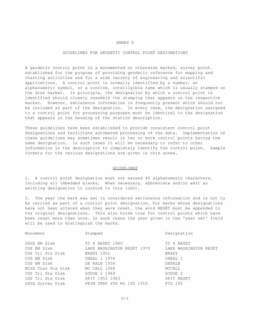
ANNEX D
GUIDELINES FOR GEODETIC CONTROL POINT DESIGNATIONS
A geodetic control point is a monumented or otherwise marked, survey point,established for the purpose of providing geodetic reference for mapping andcharting activities and for a wide variety of engineering and scientificapplications. A control point is normally identified by a number, analphanumeric symbol, or a concise, intelligible name which is usually stamped onthe disk marker. In principle, the designation by which a control point isidentified should closely resemble the stamping that appears on the respectivemarker. However, extraneous information is frequently present which should notbe included as part of the designation. In every case, the designation assignedto a control point for processing purposes must be identical to the designationthat appears in the heading of the station description.
These guidelines have been established to provide consistent control pointdesignations and facilitate automated processing of the data. Implementation ofthese guidelines may sometimes result in two or more control points having thesame designation. In such cases it will be necessary to refer to otherinformation in the description to completely identify the control point. Sampleformats for the various designations are given in this annex.
GUIDELINES
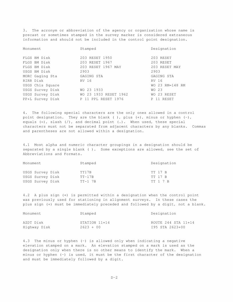
1. A control point designation must not exceed 40 alphanumeric characters,including all imbedded blanks. When necessary, abbreviate and/or edit anexisting designation to conform to this limit.
2. The year the mark was set is considered extraneous information and is not tobe carried as part of a control point designation. For marks whose designationshave not been altered when they were reset, the word RESET must be appended tothe original designations. This also holds true for control points which havebeen reset more than once. In such cases the year given in the "year set" fieldwill be used to distinguish the marks.
Monument Stamped Designation
USGS BM Disk TT 8 RESET 1965 TT 8 RESETCGS BM Disk LAKE WASHINGTON RESET 1970 LAKE WASHINGTON RESETCGS Tri Sta Disk BRADY 1951 BRADYCGS BM Disk ONEAL 1 1954 ONEAL 1CGS BM Disk DE KALB 1934 DEKALBNCGS Trav Sta Disk MC CALL 1968 MCCALLCGS Tri Sta Disk DODGE 2 1969 DODGE 2CGS Tri Sta Disk SPIT 1953 1983 SPIT RESETUSGS Survey Disk PRIM TRAV STA NO 185 1915 PTS 185
D-1
3. The acronym or abbreviation of the agency or organization whose name isprecast or sometimes stamped in the survey marker is considered extraneousinformation and should not be included in the control point designation.
Monument Stamped Designation
FLGS BM Disk 203 RESET 1950 203 RESETFLGS BM Disk 203 RESET 1967 203 RESETFLGS BM Disk 203 RESET 1967 MAY 203 RESET MAYUSGS BM Disk 2903 2903 MORC Gaging Sta GAGING STA GAGING STARIRR Disk RV 16 RV 16USGS Chis Square WO 23 RM=148 RMUSGS Survey Disk WO 23 1933 WO 23USGS Survey Disk WO 23 1933 RESET 1962 WO 23 RESETPP+L Survey Disk P 11 PPL RESET 1976 P 11 RESET
4. The following special characters are the only ones allowed in a controlpoint designation. They are the blank ( ), plus (+), minus or hyphen (-),equals (=), slash (/), and decimal point (.). When used, these specialcharacters must not be separated from adjacent characters by any blanks. Commasand parentheses are not allowed within a designation.
4.1 Most alpha and numeric character groupings in a designation should beseparated by a single blank ( ). Some exceptions are allowed, see the set ofAbbreviations and Formats.
Monument Stamped Designation
USGS Survey Disk TT17B TT 17 B USGS Survey Disk TT-17B TT 17 B USGS Survey Disk TT-1 7B TT 1 7 B
4.2 A plus sign (+) is permitted within a designation when the control pointwas previously used for stationing in alignment surveys. In these cases theplus sign (+) must be immediately preceded and followed by a digit, not a blank.
Monument Stamped Designation
AZDT Disk STATION 11+14 ROUTE 244 STA 11+14Highway Disk 2623 + 00 I95 STA 2623+00
4.3 The minus or hyphen (-) is allowed only when indicating a negativeelevation stamped on a mark. An elevation stamped on a mark is used as thedesignation only when there is no other means to identify the mark. When aminus or hyphen (-) is used, it must be the first character of the designationand must be immediately followed by a digit.
D-2
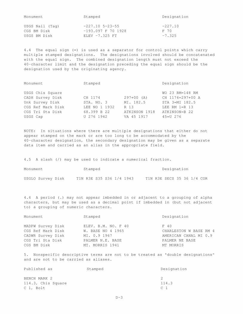
Monument Stamped Designation
USGS Nail (Tag) -227.10 5-23-55 -227.10CGS BM Disk -193.097 F 70 1928 F 70USGS BM Disk ELEV -7.325 FT -7.325
4.4 The equal sign (=) is used as a separator for control points which carrymultiple stamped designations. The designations involved should be concatenatedwith the equal sign. The combined designation length must not exceed the40-character limit and the designation preceding the equal sign should be thedesignation used by the originating agency.
Monument Stamped Designation
USGS Chis Square WO 23 RM=148 RMCADH Survey Disk CH 1174 297+00 (A) CH 1174=297+00 A Unk Survey Disk STA. NO. 3 MI. 182.5 STA 3=MI 182.5 CGS Ref Mark Disk LEE NO 1 1932 R 13 LEE RM 1=R 13CGS Tri Sta Disk 68.399 B 22 ATKINSON 1918 ATKINSON=B 22USGS Cap U 276 1942 VA 45 1917 45=U 276
NOTE: In situations where there are multiple designations that either do notappear stamped on the mark or are too long to be accommodated by the40-character designation, the secondary designation may be given as a separatedata item and carried as an alias in the appropriate field.
4.5 A slash (/) may be used to indicate a numerical fraction.
Monument Stamped Designation
USGLO Survey Disk T1N R3E S35 S36 1/4 1943 T1N R3E SECS 35 36 1/4 COR
4.6 A period (.) may not appear imbedded in or adjacent to a grouping of alphacharacters, but may be used as a decimal point if imbedded in (but not adjacentto) a grouping of numeric characters.
Monument Stamped Designation
MADPW Survey Disk ELEV. B.M. NO. F 40 F 40CGS Ref Mark Disk W. BASE NO 4 1965 CHARLESTON W BASE RM 4CADWR Survey Disk MI. 0.9 1967 AMERICAN CANAL MI 0.9CGS Tri Sta Disk PALMER N.E. BASE PALMER NE BASECGS BM Disk MT. MORRIS 1941 MT MORRIS
5. Nonspecific descriptive terms are not to be treated as "double designations"and are not to be carried as aliases.
Published as Stamped Designation
BENCH MARK 2 2114.3, Chis Square 114.3C 1, Bolt C 1
D-3
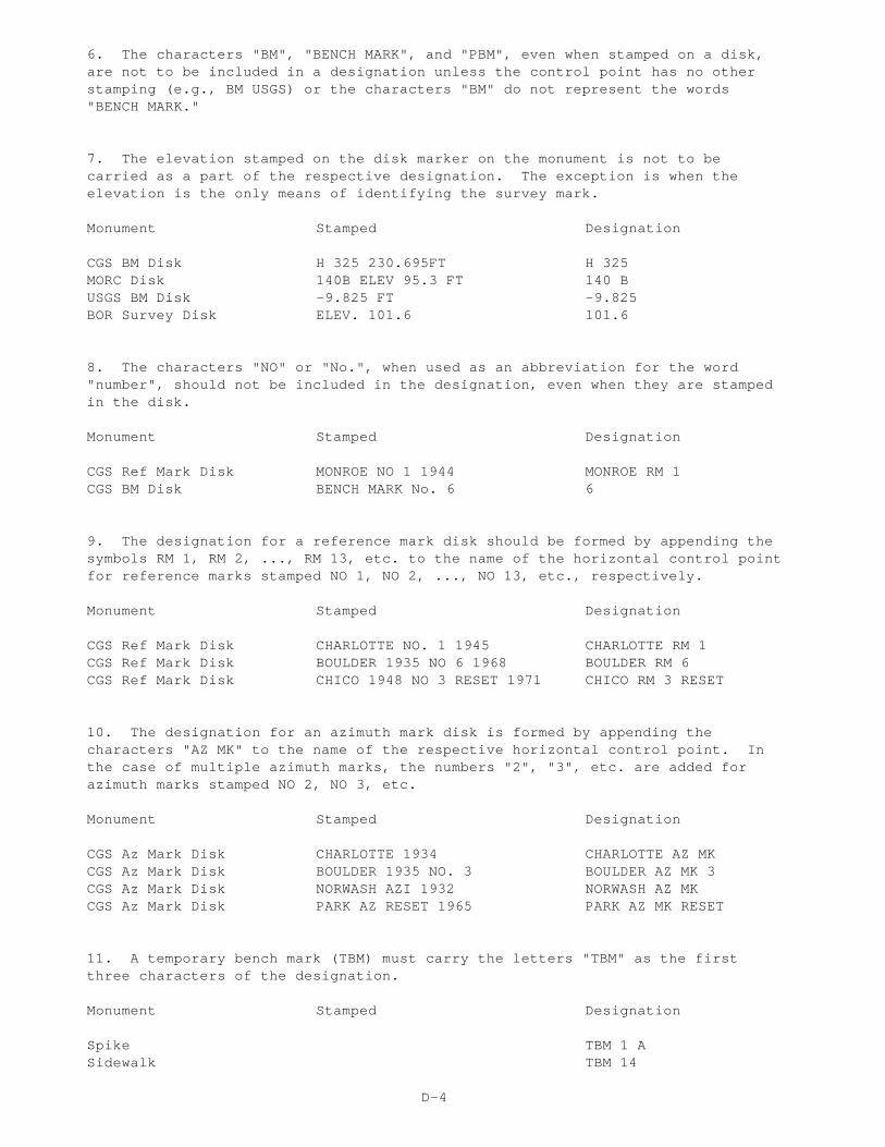
6. The characters "BM", "BENCH MARK", and "PBM", even when stamped on a disk,are not to be included in a designation unless the control point has no otherstamping (e.g., BM USGS) or the characters "BM" do not represent the words"BENCH MARK."
7. The elevation stamped on the disk marker on the monument is not to becarried as a part of the respective designation. The exception is when theelevation is the only means of identifying the survey mark.
Monument Stamped Designation
CGS BM Disk H 325 230.695FT H 325MORC Disk 140B ELEV 95.3 FT 140 B USGS BM Disk -9.825 FT -9.825 BOR Survey Disk ELEV. 101.6 101.6
8. The characters "NO" or "No.", when used as an abbreviation for the word"number", should not be included in the designation, even when they are stampedin the disk.
Monument Stamped Designation
CGS Ref Mark Disk MONROE NO 1 1944 MONROE RM 1CGS BM Disk BENCH MARK No. 6 6
9. The designation for a reference mark disk should be formed by appending thesymbols RM 1, RM 2, ..., RM 13, etc. to the name of the horizontal control pointfor reference marks stamped NO 1, NO 2, ..., NO 13, etc., respectively.
Monument Stamped Designation
CGS Ref Mark Disk CHARLOTTE NO. 1 1945 CHARLOTTE RM 1 CGS Ref Mark Disk BOULDER 1935 NO 6 1968 BOULDER RM 6CGS Ref Mark Disk CHICO 1948 NO 3 RESET 1971 CHICO RM 3 RESET
10. The designation for an azimuth mark disk is formed by appending thecharacters "AZ MK" to the name of the respective horizontal control point. Inthe case of multiple azimuth marks, the numbers "2", "3", etc. are added for azimuth marks stamped NO 2, NO 3, etc.
Monument Stamped Designation
CGS Az Mark Disk CHARLOTTE 1934 CHARLOTTE AZ MKCGS Az Mark Disk BOULDER 1935 NO. 3 BOULDER AZ MK 3CGS Az Mark Disk NORWASH AZI 1932 NORWASH AZ MKCGS Az Mark Disk PARK AZ RESET 1965 PARK AZ MK RESET
11. A temporary bench mark (TBM) must carry the letters "TBM" as the firstthree characters of the designation.
Monument Stamped Designation
Spike TBM 1 ASidewalk TBM 14
D-4
12. The National Ocean Service (NOS) has instituted a standard system ofdesignations for all tidal and water level stations operated by NOS. The systemprovides for the unique identification of all disks, staffs, etc., located atsuch stations (e.g., see Formats in this annex).
Tidal and water level bench mark designations must conform to standarddesignations adopted by the National Ocean Service. For information concerningspecific tide gage bench marks, etc., communicate with:
NOAA, National Ocean ServiceOPSD, User Services, N/CS44Attn: Water Levels1305 East-West HighwaySilver Spring, MD 20910-3281
Telephone: 1-301-713-2877 ext. 176E-mail Address: [email protected] Web Site: www.opsd.nos.noaa.gov
Whenever the need arises for a guideline to deal with a situation not coveredherein, the user is encouraged to communicate with the following technicaloffice in NGS:
Spatial Reference System Division, N/NGS2 National Geodetic Survey, NOAA1315 East-West HighwaySilver Spring, MD 20910-3282
Telephone: 1-301-713-3191E-mail Address: [email protected] Web Site: www.ngs.noaa.gov
D-5
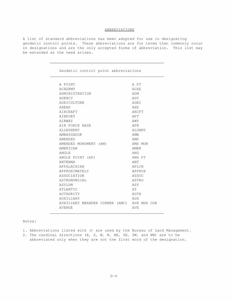
ABBREVIATIONS
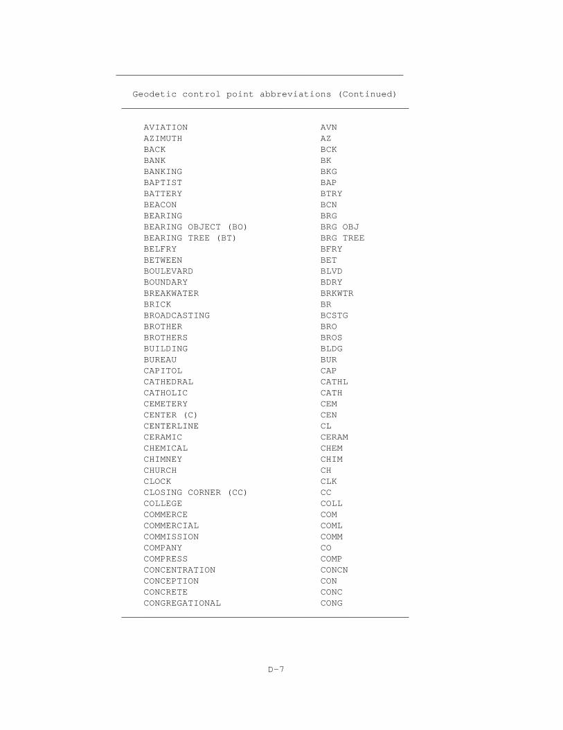
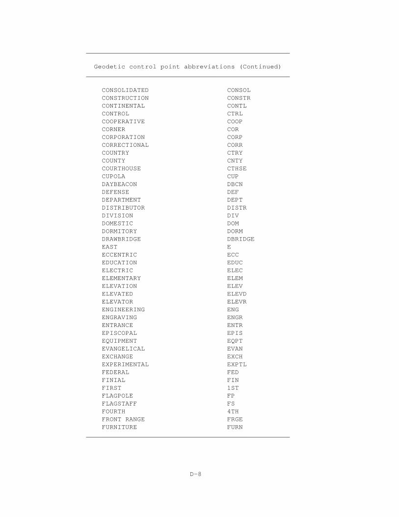
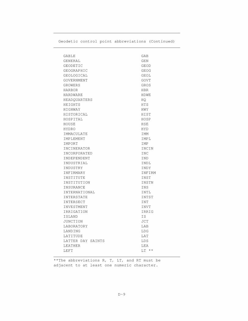
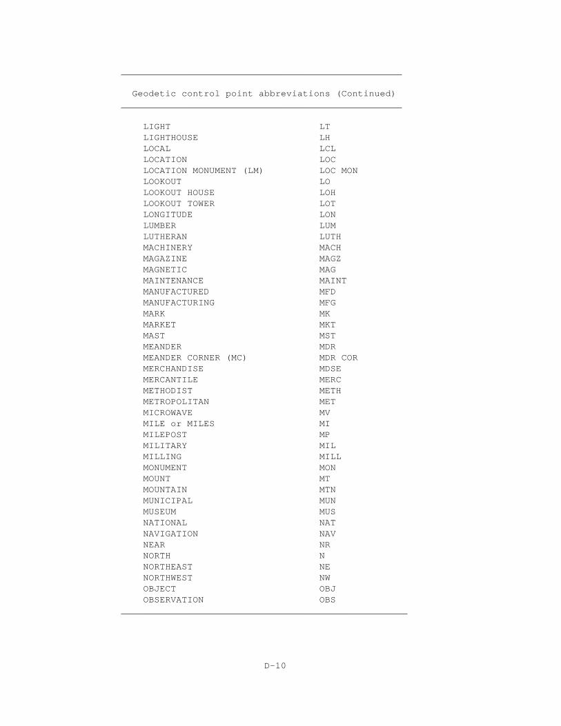
A list of standard abbreviations has been adopted for use in designatinggeodetic control points. These abbreviations are for terms that commonly occurin designations and are the only accepted forms of abbreviation. This list maybe extended as the need arises.
__________________________________________________
Geodetic control point abbreviations__________________________________________________
A POINT A PTACADEMY ACADADMINISTRATION ADMAGENCY AGYAGRICULTURE AGRIAHEAD AHDAIRCRAFT ARCFTAIRPORT APTAIRWAY AWYAIR FORCE BASE AFBALLEGHENY ALGHNYAMBASSADOR AMBAMENDED AMDAMENDED MONUMENT (AM) AMD MONAMERICAN AMERANGLE ANGANGLE POINT (AP) ANG PTANTENNA ANTAPPALACHIAN APLCNAPPROXIMATELY APPROXASSOCIATION ASSOCASTRONOMICAL ASTROASYLUM ASYATLANTIC ATAUTHORITY AUTHAUXILIARY AUXAUXILIARY MEANDER CORNER (AMC) AUX MDR CORAVENUE AVE
__________________________________________________
Notes:
1. Abbreviations listed with () are used by the Bureau of Land Management.2. The cardinal directions (E, S, W, N, NE, SE, SW, and NW) are to be abbreviated only when they are not the first word of the designation.
D-6
____________________________________________________
Geodetic control point abbreviations (Continued)____________________________________________________
AVIATION AVNAZIMUTH AZBACK BCKBANK BKBANKING BKG BAPTIST BAP BATTERY BTRY BEACON BCN BEARING BRG BEARING OBJECT (BO) BRG OBJ BEARING TREE (BT) BRG TREE BELFRY BFRY BETWEEN BET BOULEVARD BLVD BOUNDARY BDRY BREAKWATER BRKWTR BRICK BR BROADCASTING BCSTG BROTHER BRO BROTHERS BROS BUILDING BLDG BUREAU BUR CAPITOL CAP CATHEDRAL CATHL CATHOLIC CATH CEMETERY CEM CENTER (C) CEN CENTERLINE CL CERAMIC CERAM CHEMICAL CHEM CHIMNEY CHIM CHURCH CH CLOCK CLK CLOSING CORNER (CC) CC COLLEGE COLL COMMERCE COM COMMERCIAL COML COMMISSION COMM COMPANY CO COMPRESS COMP CONCENTRATION CONCN CONCEPTION CON CONCRETE CONC CONGREGATIONAL CONG
____________________________________________________
D-7
____________________________________________________ Geodetic control point abbreviations (Continued) ____________________________________________________
CONSOLIDATED CONSOL CONSTRUCTION CONSTR CONTINENTAL CONTL CONTROL CTRL COOPERATIVE COOP CORNER COR CORPORATION CORP CORRECTIONAL CORR COUNTRY CTRY COUNTY CNTY COURTHOUSE CTHSE CUPOLA CUP DAYBEACON DBCN DEFENSE DEF DEPARTMENT DEPT DISTRIBUTOR DISTR DIVISION DIV DOMESTIC DOM DORMITORY DORM DRAWBRIDGE DBRIDGE EAST E ECCENTRIC ECC EDUCATION EDUC ELECTRIC ELEC ELEMENTARY ELEM ELEVATION ELEV ELEVATED ELEVD ELEVATOR ELEVR ENGINEERING ENG ENGRAVING ENGR ENTRANCE ENTR EPISCOPAL EPIS EQUIPMENT EQPT EVANGELICAL EVAN EXCHANGE EXCH EXPERIMENTAL EXPTL FEDERAL FED FINIAL FIN FIRST 1ST FLAGPOLE FP FLAGSTAFF FS FOURTH 4TH FRONT RANGE FRGE FURNITURE FURN
____________________________________________________
D-8
____________________________________________________
Geodetic control point abbreviations (Continued) ____________________________________________________
GABLE GABGENERAL GEN GEODETIC GEOD GEOGRAPHIC GEOG GEOLOGICAL GEOL GOVERNMENT GOVT GROWERS GROS HARBOR HBR HARDWARE HDWE HEADQUARTERS HQ HEIGHTS HTS HIGHWAY HWY HISTORICAL HIST HOSPITAL HOSP HOUSE HSE HYDRO HYD IMMACULATE IMM IMPLEMENT IMPL IMPORT IMP INCINERATOR INCIN INCORPORATED INC INDEPENDENT IND INDUSTRIAL INDL INDUSTRY INDY INFIRMARY INFIRM INSTITUTE INST INSTITUTION INSTN INSURANCE INS INTERNATIONAL INTL INTERSTATE INTST INTERSECT INT INVESTMENT INVT IRRIGATION IRRIG ISLAND IS JUNCTION JCT LABORATORY LAB LANDING LDG LATITUDE LAT LATTER DAY SAINTS LDS LEATHER LEA LEFT LT **
____________________________________________________ **The abbreviations R, T, LT, and RT must be adjacent to at least one numeric character.
D-9
___________________________________________________
Geodetic control point abbreviations (Continued) ___________________________________________________
LIGHT LTLIGHTHOUSE LH LOCAL LCL LOCATION LOC LOCATION MONUMENT (LM) LOC MON LOOKOUT LO LOOKOUT HOUSE LOH LOOKOUT TOWER LOT LONGITUDE LON LUMBER LUM LUTHERAN LUTH MACHINERY MACH MAGAZINE MAGZ MAGNETIC MAG MAINTENANCE MAINT MANUFACTURED MFD MANUFACTURING MFG MARK MK MARKET MKT MAST MST MEANDER MDR MEANDER CORNER (MC) MDR COR MERCHANDISE MDSE MERCANTILE MERC METHODIST METH METROPOLITAN MET MICROWAVE MV MILE or MILES MI MILEPOST MP MILITARY MIL MILLING MILL MONUMENT MON MOUNT MT MOUNTAIN MTN MUNICIPAL MUN MUSEUM MUS NATIONAL NAT NAVIGATION NAV NEAR NR NORTH N NORTHEAST NE NORTHWEST NW OBJECT OBJ OBSERVATION OBS
____________________________________________________
D-10
____________________________________________________
Geodetic control point abbreviations (Continued) ____________________________________________________
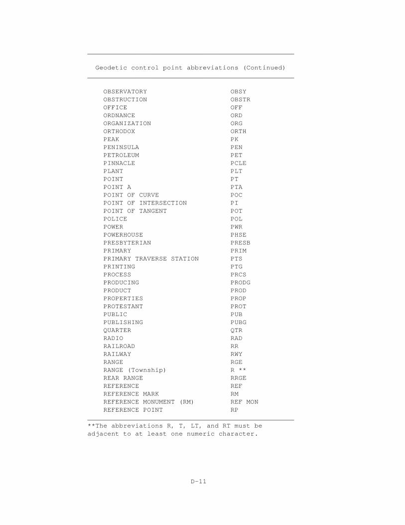
OBSERVATORY OBSY OBSTRUCTION OBSTR OFFICE OFF ORDNANCE ORD ORGANIZATION ORG ORTHODOX ORTH PEAK PK PENINSULA PEN PETROLEUM PET PINNACLE PCLE PLANT PLT POINT PT POINT A PTA POINT OF CURVE POC POINT OF INTERSECTION PI POINT OF TANGENT POT POLICE POL POWER PWR POWERHOUSE PHSE PRESBYTERIAN PRESB PRIMARY PRIM PRIMARY TRAVERSE STATION PTS PRINTING PTG PROCESS PRCS PRODUCING PRODG PRODUCT PROD PROPERTIES PROP PROTESTANT PROT PUBLIC PUB PUBLISHING PUBG QUARTER QTR RADIO RAD RAILROAD RR RAILWAY RWY RANGE RGE RANGE (Township) R ** REAR RANGE RRGE REFERENCE REF REFERENCE MARK RM REFERENCE MONUMENT (RM) REF MON REFERENCE POINT RP
____________________________________________________ **The abbreviations R, T, LT, and RT must be adjacent to at least one numeric character.
D-11
____________________________________________________
Geodetic control point abbreviations (Continued) ____________________________________________________
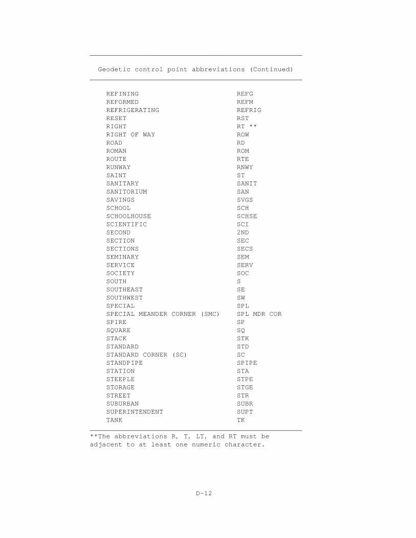
REFINING REFGREFORMED REFM REFRIGERATING REFRIG RESET RST RIGHT RT ** RIGHT OF WAY ROW ROAD RD ROMAN ROM ROUTE RTERUNWAY RNWY SAINT ST SANITARY SANIT SANITORIUM SAN SAVINGS SVGS SCHOOL SCH SCHOOLHOUSE SCHSE SCIENTIFIC SCI SECOND 2ND SECTION SEC SECTIONS SECS SEMINARY SEM SERVICE SERV SOCIETY SOC SOUTH S SOUTHEAST SE SOUTHWEST SW SPECIAL SPL SPECIAL MEANDER CORNER (SMC) SPL MDR COR SPIRE SP SQUARE SQ STACK STK STANDARD STD STANDARD CORNER (SC) SC STANDPIPE SPIPE STATION STA STEEPLE STPE STORAGE STGE STREET STR SUBURBAN SUBR SUPERINTENDENT SUPT TANK TK
____________________________________________________ **The abbreviations R, T, LT, and RT must be adjacent to at least one numeric character.
D-12
____________________________________________________
Geodetic control point abbreviations (Continued) ____________________________________________________
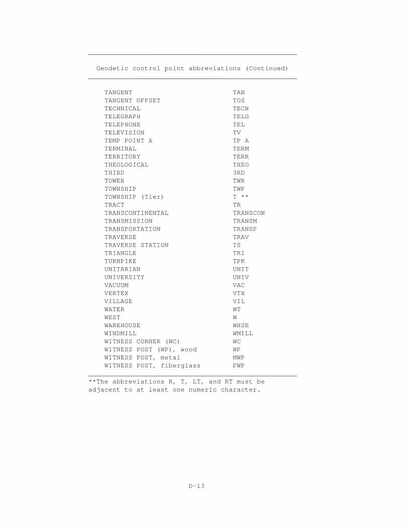
TANGENT TAN TANGENT OFFSET TOS TECHNICAL TECH TELEGRAPH TELG TELEPHONE TEL TELEVISION TV TEMP POINT A TP A TERMINAL TERM TERRITORY TERR THEOLOGICAL THEO THIRD 3RD TOWER TWR TOWNSHIP TWP TOWNSHIP (Tier) T ** TRACT TR TRANSCONTINENTAL TRANSCON TRANSMISSION TRANSM TRANSPORTATION TRANSP TRAVERSE TRAV TRAVERSE STATION TS TRIANGLE TRI TURNPIKE TPK UNITARIAN UNIT UNIVERSITY UNIV VACUUM VAC VERTEX VTX VILLAGE VIL WATER WT WEST W WAREHOUSE WHSE WINDMILL WMILL WITNESS CORNER (WC) WC WITNESS POST (WP), wood WP WITNESS POST, metal MWPWITNESS POST, fiberglass FWP
____________________________________________________ **The abbreviations R, T, LT, and RT must be adjacent to at least one numeric character.
D-13
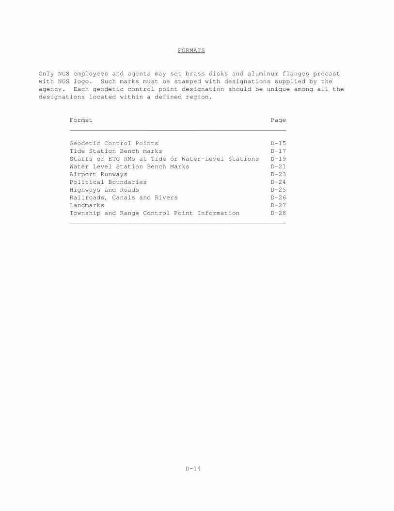
FORMATS
Only NGS employees and agents may set brass disks and aluminum flanges precastwith NGS logo. Such marks must be stamped with designations supplied by theagency. Each geodetic control point designation should be unique among all thedesignations located within a defined region.
Format Page________________________________________________________
Geodetic Control Points D-15Tide Station Bench marks D-17Staffs or ETG RMs at Tide or Water-Level Stations D-19Water Level Station Bench Marks D-21Airport Runways D-23Political Boundaries D-24Highways and Roads D-25Railroads, Canals and Rivers D-26Landmarks D-27Township and Range Control Point Information D-28________________________________________________________
D-14
Geodetic control points______________________________________________________________________________
FORMAT: NAME SPECIAL______________________________________________________________________________
1. NAME
A. The following method is generally used for naming vertical controlpoints (bench marks). The first mark established in a state isdesignated "A", then "B" and so on through the alphabet, except theletters "I" and "O" which are not used because they are too easily confused with the numbers "1" and "O". The next series of marks is identified as "A 1", "B 1", etc.; then "A 2", "B 2", etc., and so on through the alphabet. In some cases, more than one letter is usedto distinguish between bench marks that have accidentally been giventhe same name in the same state.
B. The following method is generally used for naming a horizontal control point (triangulation or traverse). The name should serve
not only to identify the station but to suggest the local geographiclocation or feature. The name should be used only once within acounty and preferably a given state. Therefore, use sufficientvariety to avoid duplication. A short name is desirable, but if alonger name is required to properly serve the purpose, it should beused. In those cases where a well known geographical feature in thevicinity is used, or the name of a local landowner, the name shouldbe spelled correctly.
2. SPECIAL USE
A. These terms are used with vertical control points to distinguishbetween names used more than once in a state or to indicatedisturbance of the original bench mark (e.g., "RESET").
B. These terms are used with horizontal control points to explain alocal use or disturbance to the original mark or its designation.
____________________________________________________________________________
D-15
Examples:
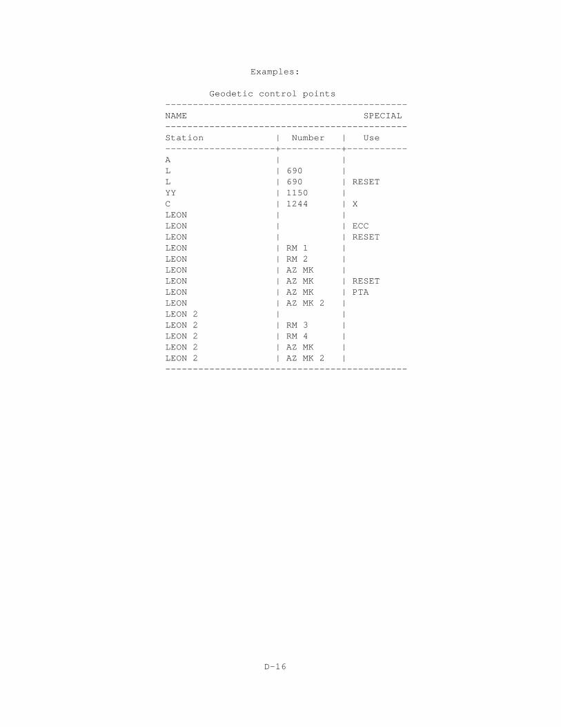
Geodetic control points -------------------------------------------- NAME SPECIAL--------------------------------------------Station | Number | Use--------------------+-----------+-----------A | |L | 690 |L | 690 | RESETYY | 1150 |C | 1244 | XLEON | |LEON | | ECCLEON | | RESETLEON | RM 1 |LEON | RM 2 |LEON | AZ MK |LEON | AZ MK | RESETLEON | AZ MK | PTALEON | AZ MK 2 |LEON 2 | |LEON 2 | RM 3 |LEON 2 | RM 4 |LEON 2 | AZ MK |LEON 2 | AZ MK 2 |--------------------------------------------
D-16
Tide station bench marks______________________________________________________________________________
FORMAT: LOCATION OBJECT SPECIAL______________________________________________________________________________
1. LOCATION Code and Station
A. The location has two parts, the first part, the CODE, is a 3-digit State code given for each geographical region.
B. The second part of the location, the STATION NUMBER, is an unique 4-digit number assigned to a particular tide station within a given
geographical area.
2. OBJECT Identification
A. The MARK USE gives information on the nature of the object which wasused.
B. The PUBLICATION NAME is used to give the proper identification of the object. In most cases, this field should be based on the stamping. If there is no stamping, use the name given in the tidal publication. In either case, this field is subject to the guidelines given in thisAnnex.
3. SPECIAL Use
This term is used to explain a local use or disturbance to the originalmark.
NOTE: If other types of marks are used in tidal surveys, see other formatrules for their primary designations; and add aliases according to thefollowing examples:
Mark type DS (Triangulation Station Mark)Stamping BREACH 1963Primary designation BREACH Alias 866 5552 TIDAL
Mark type DB (Bench Mark Disk)Stamping V 163 RESET 1984Primary designation V 163 RESETAlias 872 9871 TIDAL
______________________________________________________________________________
D-17
Examples
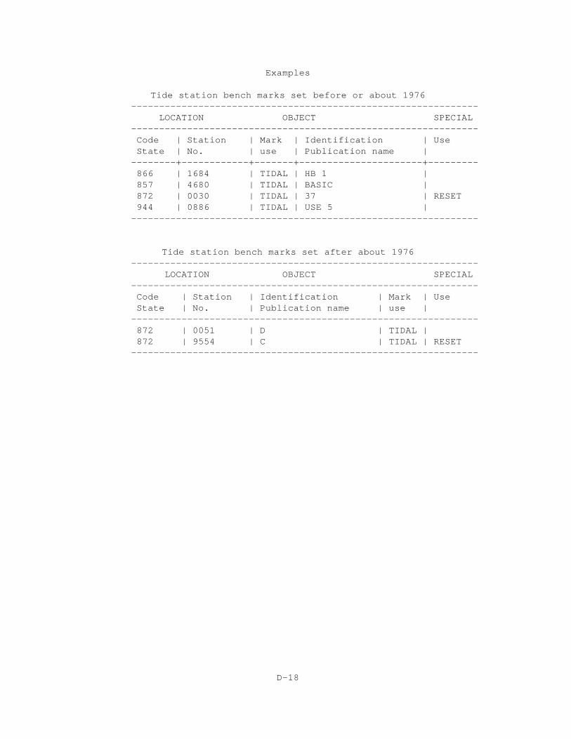
Tide station bench marks set before or about 1976-------------------------------------------------------------- LOCATION OBJECT SPECIAL-------------------------------------------------------------- Code | Station | Mark | Identification | Use State | No. | use | Publication name | --------+------------+-------+----------------------+--------- 866 | 1684 | TIDAL | HB 1 | 857 | 4680 | TIDAL | BASIC | 872 | 0030 | TIDAL | 37 | RESET 944 | 0886 | TIDAL | USE 5 | --------------------------------------------------------------
Tide station bench marks set after about 1976-------------------------------------------------------------- LOCATION OBJECT SPECIAL--------------------------------------------------------------
Code | Station | Identification | Mark | Use State | No. | Publication name | use |
-------------------------------------------------------------- 872 | 0051 | D | TIDAL | 872 | 9554 | C | TIDAL | RESET --------------------------------------------------------------
D-18
Staffs or electric tape gage (ETG) reading marks at tide or water-level stations
______________________________________________________________________________
FORMAT: TEMPORAL LOCATION OBJECT SPECIAL______________________________________________________________________________
1. TEMPORAL Reference
The Temporal Reference is identified by setting the term "TBM" in front ofthe location.
2. LOCATION Code and Station
A. The location has two parts, the first, the CODE, is either a 3-digit STATE number code for a State or a 3-digit CUTTER code for defining apart of a lake or channel.
B. The second part of the location, the STATION NUMBER, is an unique 4-digit number assigned to a particular tide or water level stationwithin a given geographical area.
3. OBJECT Identification
The Object Identification gives information on the nature of the objectthat was used.
4. SPECIAL UseThese terms are used to indicate the graduation of the tide or waterlevel staff on which the level rod was placed.
______________________________________________________________________________
D-19
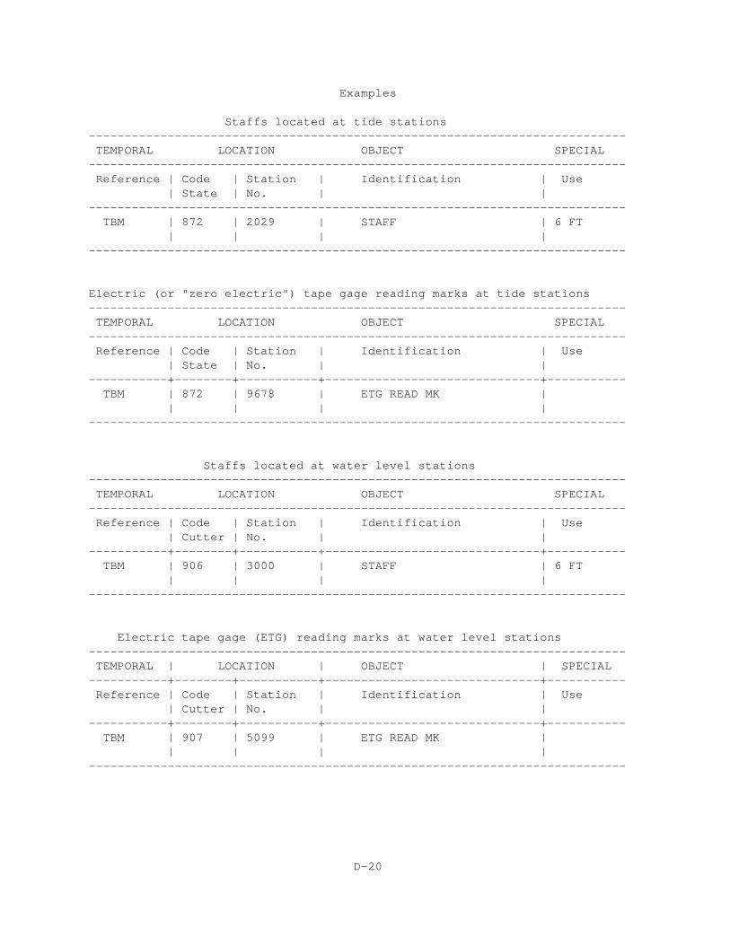
Examples
Staffs located at tide stations---------------------------------------------------------------------------TEMPORAL LOCATION OBJECT SPECIAL
---------------------------------------------------------------------------Reference | Code | Station | Identification | Use
| State | No. | |---------------------------------------------------------------------------
TBM | 872 | 2029 | STAFF | 6 FT | | | |
---------------------------------------------------------------------------
Electric (or "zero electric") tape gage reading marks at tide stations---------------------------------------------------------------------------TEMPORAL LOCATION OBJECT SPECIAL
---------------------------------------------------------------------------Reference | Code | Station | Identification | Use
| State | No. | |-----------+--------+-----------+------------------------------+-----------
TBM | 872 | 9678 | ETG READ MK | | | | |
---------------------------------------------------------------------------
Staffs located at water level stations ---------------------------------------------------------------------------TEMPORAL LOCATION OBJECT SPECIAL
---------------------------------------------------------------------------Reference | Code | Station | Identification | Use
| Cutter | No. | |-----------+--------+-----------+------------------------------+-----------
TBM | 906 | 3000 | STAFF | 6 FT | | | |
---------------------------------------------------------------------------
Electric tape gage (ETG) reading marks at water level stations---------------------------------------------------------------------------TEMPORAL | LOCATION | OBJECT | SPECIAL
-----------+--------+-----------+------------------------------+-----------Reference | Code | Station | Identification | Use
| Cutter | No. | |-----------+--------+-----------+------------------------------+-----------
TBM | 907 | 5099 | ETG READ MK | | | | |
---------------------------------------------------------------------------
D-20
Water level station bench marks______________________________________________________________________________
FORMAT: LOCATION OBJECT SPECIAL______________________________________________________________________________
1. LOCATION Code and Station
A. The first part of the location is the 3-digit code for defining a part of a lake or channel within the CUTTER Code System.
B. The second part of the location, the STATION NUMBER, is a unique4-digit number assigned to the water level station within a givengeographical area.
2. OBJECT Identification
In most cases, this field should be based on the stamping. If there is no stamping, use the name given in the water level publication.In either case, this field is subject to the guidelines given in this annex.
3. SPECIAL Use
These character strings are used to explain some local use or disturbance to the original mark.
NOTE: If other types of marks are used in water level surveys, see otherformat rules for their primary designation and add an alias accordingto the following example:
Mark type F (flange-encased rod)Stamping C 234 1980 (on logo cap)Primary designation C 234 Alias 906 3087
______________________________________________________________________________
D-21
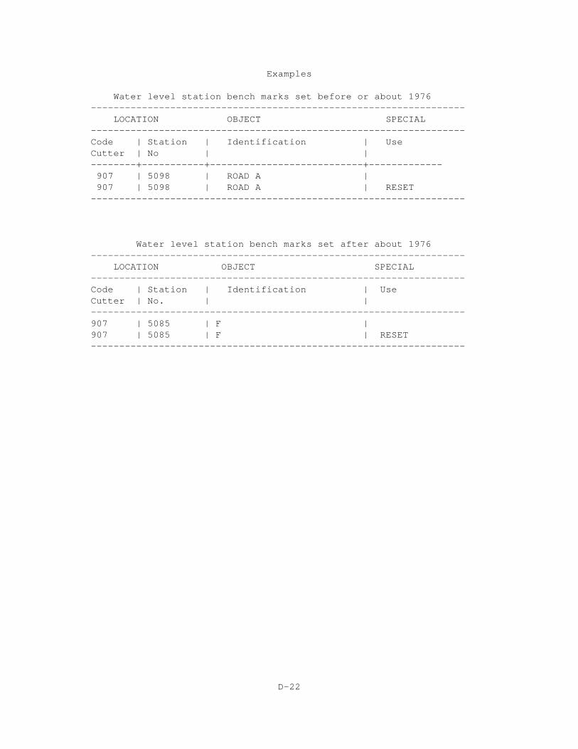
Examples
Water level station bench marks set before or about 1976------------------------------------------------------------------
LOCATION OBJECT SPECIAL------------------------------------------------------------------ Code | Station | Identification | Use Cutter | No | |--------+-----------+---------------------------+------------- 907 | 5098 | ROAD A | 907 | 5098 | ROAD A | RESET------------------------------------------------------------------
Water level station bench marks set after about 1976------------------------------------------------------------------
LOCATION OBJECT SPECIAL------------------------------------------------------------------ Code | Station | Identification | Use Cutter | No. | | ------------------------------------------------------------------907 | 5085 | F | 907 | 5085 | F | RESET------------------------------------------------------------------
D-22
Airport runways______________________________________________________________________________
FORMAT: ALIGNMENT OBJECT LOCATION SPECIAL______________________________________________________________________________
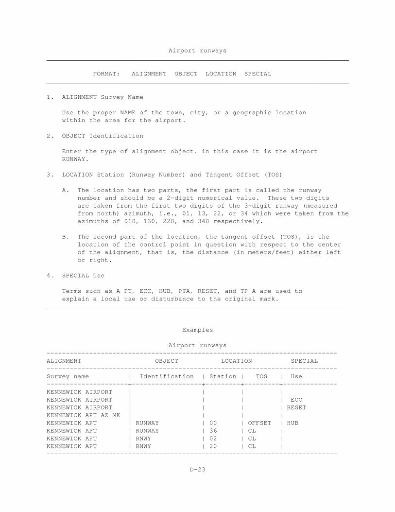
1. ALIGNMENT Survey Name
Use the proper NAME of the town, city, or a geographic location within the area for the airport.
2. OBJECT Identification
Enter the type of alignment object, in this case it is the airport RUNWAY.
3. LOCATION Station (Runway Number) and Tangent Offset (TOS)
A. The location has two parts, the first part is called the runway number and should be a 2-digit numerical value. These two digits are taken from the first two digits of the 3-digit runway (measured from north) azimuth, i.e., 01, 13, 22, or 34 which were taken from theazimuths of 010, 130, 220, and 340 respectively.
B. The second part of the location, the tangent offset (TOS), is the location of the control point in question with respect to the center of the alignment, that is, the distance (in meters/feet) either left or right.
4. SPECIAL Use
Terms such as A PT, ECC, HUB, PTA, RESET, and TP A are used to explain a local use or disturbance to the original mark.
______________________________________________________________________________
Examples
Airport runways---------------------------------------------------------------------------ALIGNMENT OBJECT LOCATION SPECIAL---------------------------------------------------------------------------Survey name | Identification | Station | TOS | Use---------------------+------------------+---------+---------+--------------KENNEWICK AIRPORT | | | |KENNEWICK AIRPORT | | | | ECCKENNEWICK AIRPORT | | | | RESETKENNEWICK APT AZ MK | | | |KENNEWICK APT | RUNWAY | 00 | OFFSET | HUBKENNEWICK APT | RUNWAY | 36 | CL |KENNEWICK APT | RNWY | 02 | CL |KENNEWICK APT | RNWY | 20 | CL |---------------------------------------------------------------------------
D-23
Political boundaries______________________________________________________________________________
FORMAT: ALIGNMENT OBJECT DESIGNATE POLITICAL SPECIAL______________________________________________________________________________
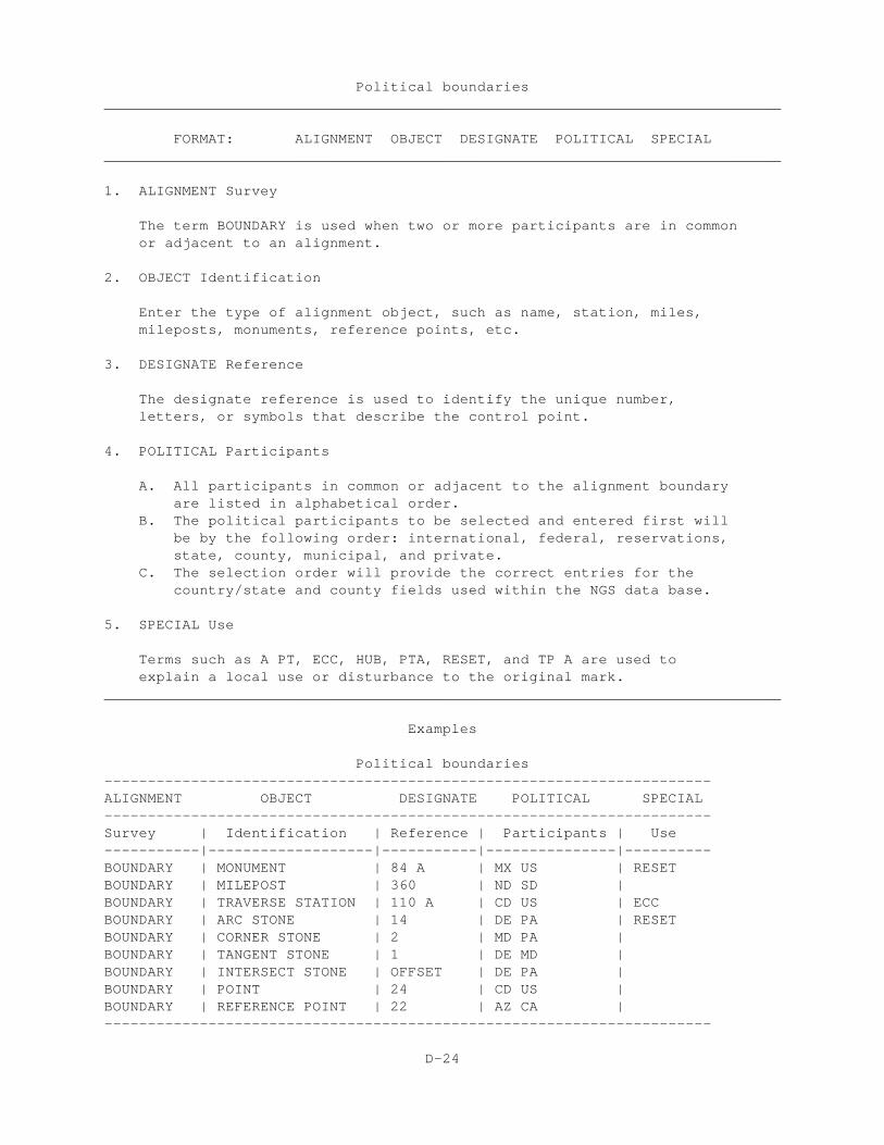
1. ALIGNMENT Survey
The term BOUNDARY is used when two or more participants are in common or adjacent to an alignment.
2. OBJECT Identification
Enter the type of alignment object, such as name, station, miles, mileposts, monuments, reference points, etc.
3. DESIGNATE Reference
The designate reference is used to identify the unique number, letters, or symbols that describe the control point.
4. POLITICAL Participants
A. All participants in common or adjacent to the alignment boundaryare listed in alphabetical order.
B. The political participants to be selected and entered first willbe by the following order: international, federal, reservations,state, county, municipal, and private.
C. The selection order will provide the correct entries for thecountry/state and county fields used within the NGS data base.
5. SPECIAL Use
Terms such as A PT, ECC, HUB, PTA, RESET, and TP A are used to explain a local use or disturbance to the original mark.
______________________________________________________________________________
Examples
Political boundaries----------------------------------------------------------------------ALIGNMENT OBJECT DESIGNATE POLITICAL SPECIAL----------------------------------------------------------------------Survey | Identification | Reference | Participants | Use-----------|-------------------|-----------|---------------|----------BOUNDARY | MONUMENT | 84 A | MX US | RESETBOUNDARY | MILEPOST | 360 | ND SD |BOUNDARY | TRAVERSE STATION | 110 A | CD US | ECCBOUNDARY | ARC STONE | 14 | DE PA | RESETBOUNDARY | CORNER STONE | 2 | MD PA |BOUNDARY | TANGENT STONE | 1 | DE MD |BOUNDARY | INTERSECT STONE | OFFSET | DE PA |BOUNDARY | POINT | 24 | CD US |BOUNDARY | REFERENCE POINT | 22 | AZ CA |----------------------------------------------------------------------
D-24
Highways and roads______________________________________________________________________________
FORMAT: ALIGNMENT OBJECT LOCATION SPECIAL______________________________________________________________________________
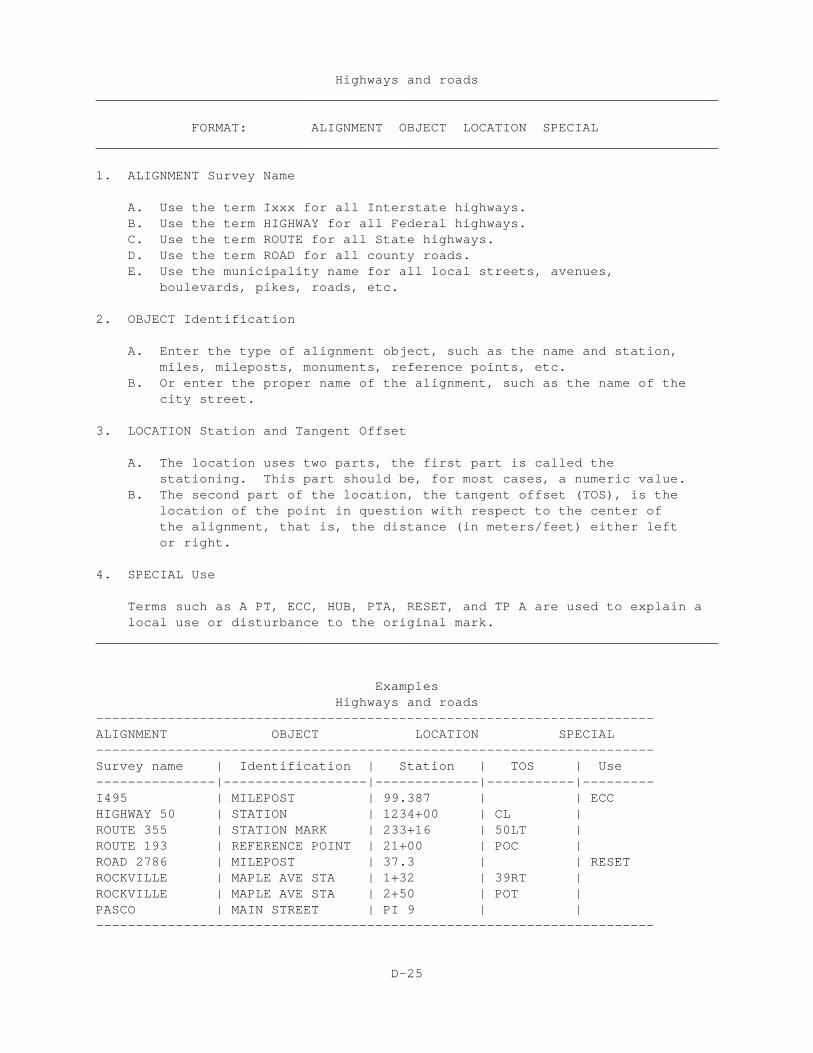
1. ALIGNMENT Survey Name
A. Use the term Ixxx for all Interstate highways.B. Use the term HIGHWAY for all Federal highways.C. Use the term ROUTE for all State highways.D. Use the term ROAD for all county roads.E. Use the municipality name for all local streets, avenues,
boulevards, pikes, roads, etc.
2. OBJECT Identification
A. Enter the type of alignment object, such as the name and station, miles, mileposts, monuments, reference points, etc.
B. Or enter the proper name of the alignment, such as the name of the city street.
3. LOCATION Station and Tangent Offset
A. The location uses two parts, the first part is called the stationing. This part should be, for most cases, a numeric value.
B. The second part of the location, the tangent offset (TOS), is thelocation of the point in question with respect to the center ofthe alignment, that is, the distance (in meters/feet) either leftor right.
4. SPECIAL Use
Terms such as A PT, ECC, HUB, PTA, RESET, and TP A are used to explain alocal use or disturbance to the original mark.
______________________________________________________________________________
ExamplesHighways and roads
----------------------------------------------------------------------ALIGNMENT OBJECT LOCATION SPECIAL----------------------------------------------------------------------Survey name | Identification | Station | TOS | Use---------------|------------------|-------------|-----------|---------I495 | MILEPOST | 99.387 | | ECCHIGHWAY 50 | STATION | 1234+00 | CL |ROUTE 355 | STATION MARK | 233+16 | 50LT |ROUTE 193 | REFERENCE POINT | 21+00 | POC |ROAD 2786 | MILEPOST | 37.3 | | RESETROCKVILLE | MAPLE AVE STA | 1+32 | 39RT |ROCKVILLE | MAPLE AVE STA | 2+50 | POT |PASCO | MAIN STREET | PI 9 | |----------------------------------------------------------------------
D-25
Railroads, canals and rivers______________________________________________________________________________
FORMAT: ALIGNMENT OBJECT LOCATION SPECIAL______________________________________________________________________________
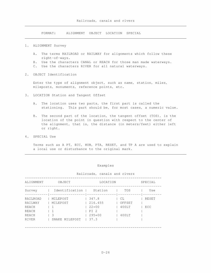
1. ALIGNMENT Survey
A. The terms RAILROAD or RAILWAY for alignments which follow these right-of-ways.B. Use the characters CANAL or REACH for those man made waterways.C. Use the characters RIVER for all natural waterways.
2. OBJECT Identification
Enter the type of alignment object, such as name, station, miles,mileposts, monuments, reference points, etc.
3. LOCATION Station and Tangent Offset
A. The location uses two parts, the first part is called thestationing. This part should be, for most cases, a numeric value.
B. The second part of the location, the tangent offset (TOS), is thelocation of the point in question with respect to the center ofthe alignment, that is, the distance (in meters/feet) either leftor right.
4. SPECIAL Use
Terms such as A PT, ECC, HUB, PTA, RESET, and TP A are used to explaina local use or disturbance to the original mark.
______________________________________________________________________________
Examples
Railroads, canals and rivers------------------------------------------------------------------ALIGNMENT OBJECT LOCATION SPECIAL------------------------------------------------------------------Survey | Identification | Station | TOS | Use-----------|-----------------|--------------|-----------|---------RAILROAD | MILEPOST | 347.8 | CL | RESETRAILWAY | MILEPOST | 216.455 | OFFSET |REACH | 1 | 22+00 | 400LT | ECCREACH | 1 | PI 2 | |REACH | 3 | 295+00 | 400LT |RIVER | SNAKE MILEPOST | 37.3 | |
------------------------------------------------------------------
D-26
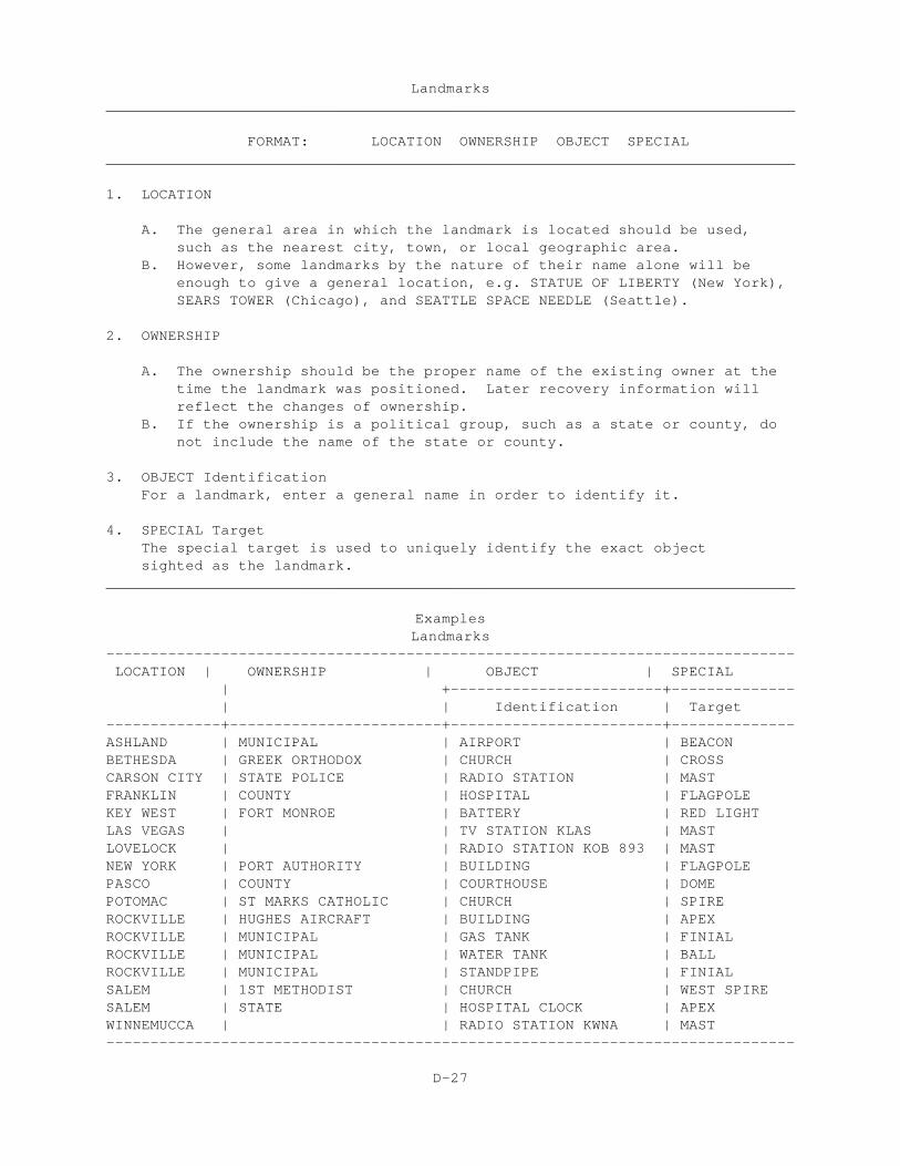
Landmarks______________________________________________________________________________
FORMAT: LOCATION OWNERSHIP OBJECT SPECIAL______________________________________________________________________________
1. LOCATION
A. The general area in which the landmark is located should be used, such as the nearest city, town, or local geographic area.
B. However, some landmarks by the nature of their name alone will be enough to give a general location, e.g. STATUE OF LIBERTY (New York), SEARS TOWER (Chicago), and SEATTLE SPACE NEEDLE (Seattle).
2. OWNERSHIP
A. The ownership should be the proper name of the existing owner at the time the landmark was positioned. Later recovery information will reflect the changes of ownership.
B. If the ownership is a political group, such as a state or county, do not include the name of the state or county.
3. OBJECT IdentificationFor a landmark, enter a general name in order to identify it.
4. SPECIAL TargetThe special target is used to uniquely identify the exact object sighted as the landmark.
______________________________________________________________________________
ExamplesLandmarks
------------------------------------------------------------------------------ LOCATION | OWNERSHIP | OBJECT | SPECIAL | +------------------------+-------------- | | Identification | Target-------------+------------------------+------------------------+--------------ASHLAND | MUNICIPAL | AIRPORT | BEACONBETHESDA | GREEK ORTHODOX | CHURCH | CROSSCARSON CITY | STATE POLICE | RADIO STATION | MAST FRANKLIN | COUNTY | HOSPITAL | FLAGPOLEKEY WEST | FORT MONROE | BATTERY | RED LIGHTLAS VEGAS | | TV STATION KLAS | MASTLOVELOCK | | RADIO STATION KOB 893 | MASTNEW YORK | PORT AUTHORITY | BUILDING | FLAGPOLEPASCO | COUNTY | COURTHOUSE | DOMEPOTOMAC | ST MARKS CATHOLIC | CHURCH | SPIREROCKVILLE | HUGHES AIRCRAFT | BUILDING | APEXROCKVILLE | MUNICIPAL | GAS TANK | FINIALROCKVILLE | MUNICIPAL | WATER TANK | BALLROCKVILLE | MUNICIPAL | STANDPIPE | FINIALSALEM | 1ST METHODIST | CHURCH | WEST SPIRESALEM | STATE | HOSPITAL CLOCK | APEXWINNEMUCCA | | RADIO STATION KWNA | MAST------------------------------------------------------------------------------
D-27
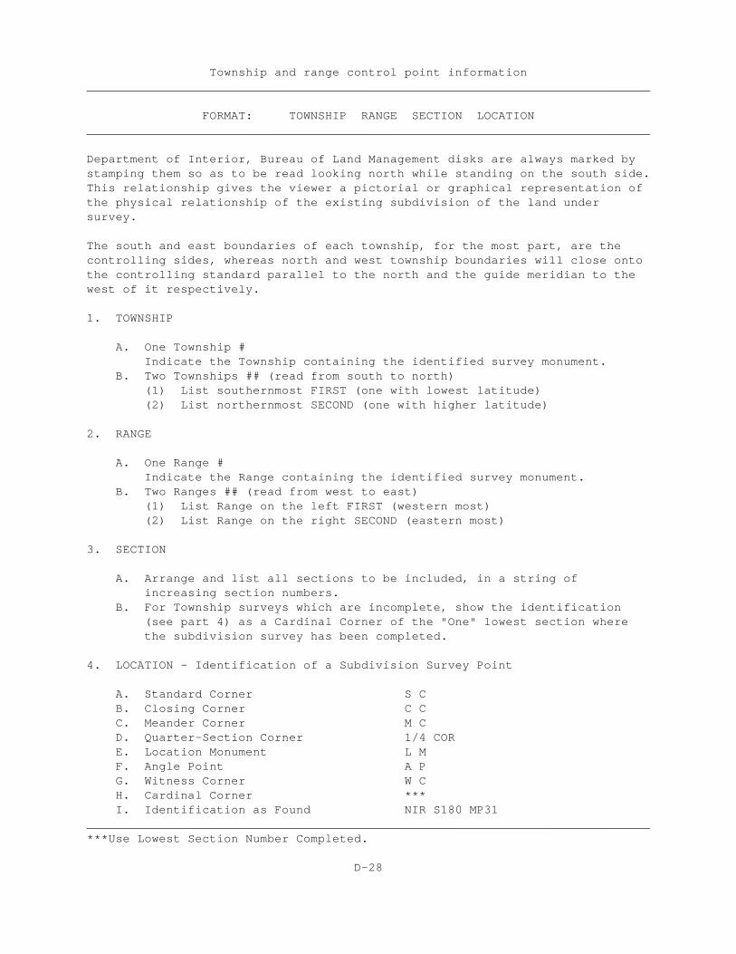
Township and range control point information______________________________________________________________________________
FORMAT: TOWNSHIP RANGE SECTION LOCATION______________________________________________________________________________
Department of Interior, Bureau of Land Management disks are always marked bystamping them so as to be read looking north while standing on the south side. This relationship gives the viewer a pictorial or graphical representation of the physical relationship of the existing subdivision of the land undersurvey.
The south and east boundaries of each township, for the most part, are thecontrolling sides, whereas north and west township boundaries will close onto the controlling standard parallel to the north and the guide meridian to the west of it respectively.
1. TOWNSHIP
A. One Township #Indicate the Township containing the identified survey monument.
B. Two Townships ## (read from south to north)(1) List southernmost FIRST (one with lowest latitude)(2) List northernmost SECOND (one with higher latitude)
2. RANGE
A. One Range #Indicate the Range containing the identified survey monument.
B. Two Ranges ## (read from west to east)(1) List Range on the left FIRST (western most)(2) List Range on the right SECOND (eastern most)
3. SECTION
A. Arrange and list all sections to be included, in a string ofincreasing section numbers.
B. For Township surveys which are incomplete, show the identification (see part 4) as a Cardinal Corner of the "One" lowest section wherethe subdivision survey has been completed.
4. LOCATION - Identification of a Subdivision Survey Point
A. Standard Corner S CB. Closing Corner C CC. Meander Corner M CD. Quarter-Section Corner 1/4 CORE. Location Monument L MF. Angle Point A PG. Witness Corner W CH. Cardinal Corner ***I. Identification as Found NIR S180 MP31
______________________________________________________________________________***Use Lowest Section Number Completed.
D-28
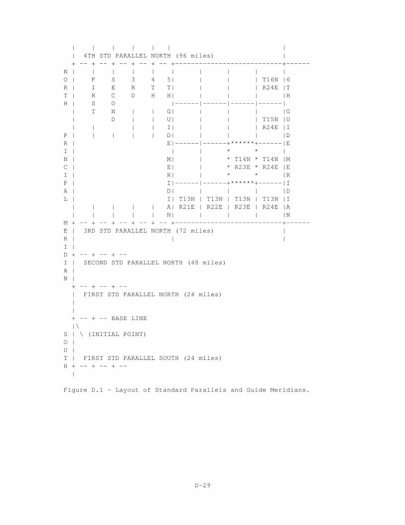
| | | | | | | | 4TH STD PARALLEL NORTH (96 miles) | + -- + -- + -- + -- + -- +---------------------------+------N | | | | | | | | | |O | F S 3 4 5| | | | T16N |6R | I E R T T| | | | R24E |TT | R C D H H| | | | |HH | S O |------|------|------|------|
| T N | | G| | | | |G | D | | U| | | | T15N |U
| | | | I| | | | R24E |IP | | | | | D| | | | |DR | E|------|------+******+------|EI | | | * * |N | M| | * T14N * T14N |MC | E| | * R23E * R24E |EI | R| | * * |RP | I|------|------+******+------|IA | D| | | | |DL | I| T13N | T13N | T13N | T13N |I | | | | | A| R21E | R22E | R23E | R24E |A | | | | | N| | | | |N
M + -- + -- + -- + -- + -- +---------------------------+------E | 3RD STD PARALLEL NORTH (72 miles) |R | | |I |D + -- + -- + --I | SECOND STD PARALLEL NORTH (48 miles)A |N | + -- + -- + -- | FIRST STD PARALLEL NORTH (24 miles) |
| + -- + -- BASE LINE |\S | \ (INITIAL POINT)O |U |T | FIRST STD PARALLEL SOUTH (24 miles)H + -- + -- + -- |
Figure D.1 - Layout of Standard Parallels and Guide Meridians.
D-29
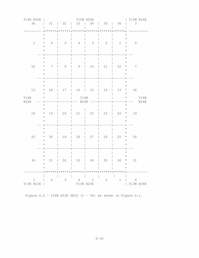
T15N R22E | T15N R23E | T15N R24E36 | 31 | 32 | 33 | 34 | 35 | 36 | 3
| | | | | | |--------- +******+******+******+******+******+******+ ---------- * | | | | | * * | | | | | * 1 * 6 | 5 | 4 | 3 | 2 | 1 * 6 * | | | | | * * | | | | | * -- +------+------+------+------+------+------+ -- * | | | | | * * | | | | | * 12 * 7 | 8 | 9 | 10 | 11 | 12 * 7 * | | | | | * * | | | | | * -- +------+------+------+------+------+------+ -- * | | | | | * * | | | | | * 13 * 18 | 17 | 16 | 15 | 14 | 13 * 18 * | | | | *T14N * | | T14N | | * T14NR22E -- +------+------+--- R23E ----+------+------+ -- R24E * | | | | * * | | | | | * 24 * 19 | 20 | 21 | 22 | 23 | 24 * 19 * | | | | | * * | | | | | * -- +------+------+------+------+------+------+ -- * | | | | | * * | | | | | * 25 * 30 | 29 | 28 | 27 | 26 | 25 * 30 * | | | | | * * | | | | | * -- +------+------+------+------+------+------+ -- * | | | | | * * | | | | | * 36 * 31 | 32 | 33 | 34 | 35 | 36 * 31 * | | | | | * * | | | | | *----------+******+******+******+******+******+******+----------- | | | | | | | 1 | 6 5 4 3 2 1 | 6T13N R22E | T13N R23E | T13N R24E
Figure D.2 - T14N R23E SECS (1 - 36) as shown in Figure D.1.
D-30
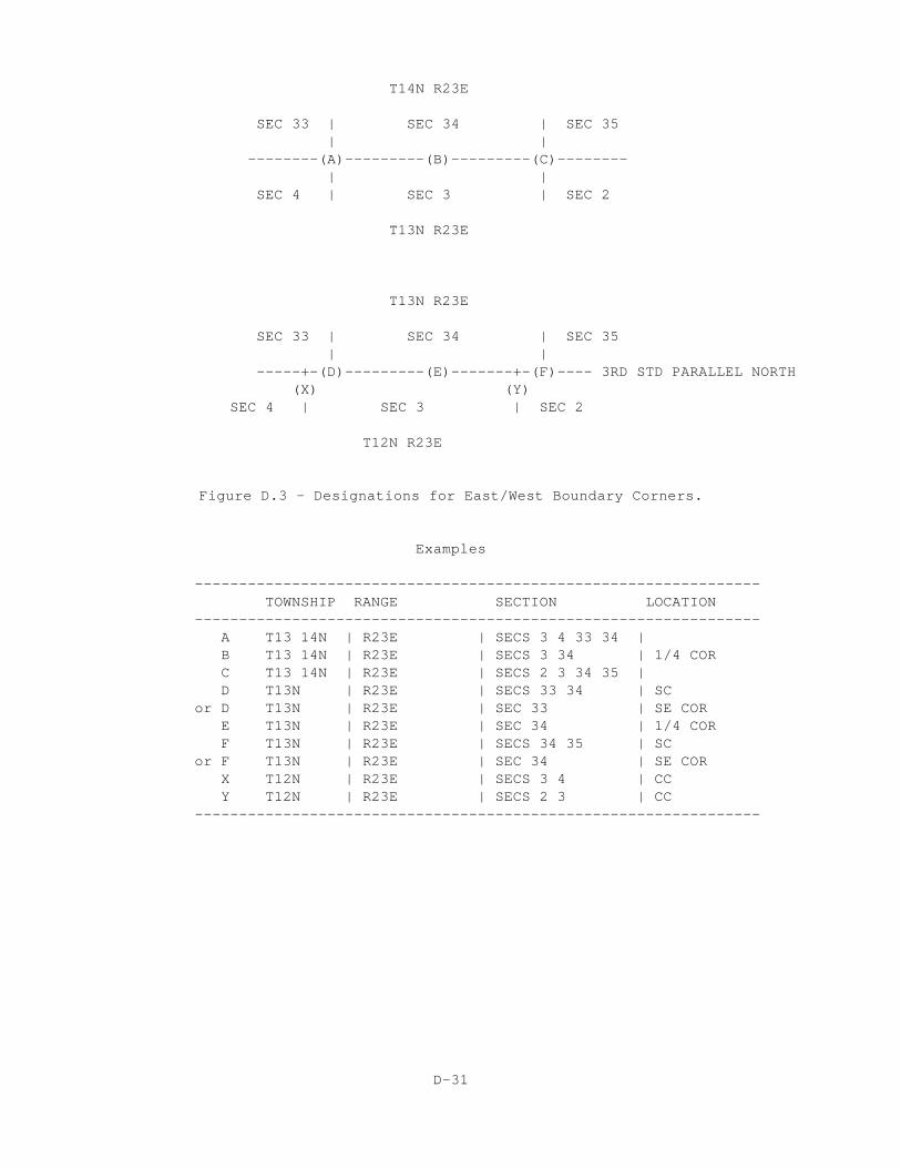
T14N R23E
SEC 33 | SEC 34 | SEC 35 | | --------(A)---------(B)---------(C)-------- | | SEC 4 | SEC 3 | SEC 2
T13N R23E
T13N R23E
SEC 33 | SEC 34 | SEC 35 | | -----+-(D)---------(E)-------+-(F)---- 3RD STD PARALLEL NORTH (X) (Y) SEC 4 | SEC 3 | SEC 2
T12N R23E
Figure D.3 - Designations for East/West Boundary Corners.
Examples
---------------------------------------------------------------- TOWNSHIP RANGE SECTION LOCATION ---------------------------------------------------------------- A T13 14N | R23E | SECS 3 4 33 34 | B T13 14N | R23E | SECS 3 34 | 1/4 COR C T13 14N | R23E | SECS 2 3 34 35 |
D T13N | R23E | SECS 33 34 | SC or D T13N | R23E | SEC 33 | SE COR E T13N | R23E | SEC 34 | 1/4 COR F T13N | R23E | SECS 34 35 | SC or F T13N | R23E | SEC 34 | SE COR X T12N | R23E | SECS 3 4 | CC Y T12N | R23E | SECS 2 3 | CC ----------------------------------------------------------------
D-31
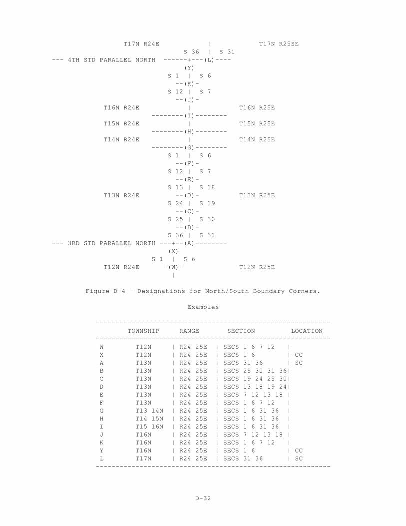
T17N R24E | T17N R25SE S 36 | S 31 --- 4TH STD PARALLEL NORTH ------+---(L)---- (Y) S 1 | S 6 --(K)- S 12 | S 7 --(J)- T16N R24E | T16N R25E --------(I)-------- T15N R24E | T15N R25E --------(H)-------- T14N R24E | T14N R25E --------(G)-------- S 1 | S 6 --(F)- S 12 | S 7 --(E)- S 13 | S 18 T13N R24E --(D)- T13N R25E S 24 | S 19 --(C)- S 25 | S 30 --(B)- S 36 | S 31 --- 3RD STD PARALLEL NORTH ---+--(A)-------- (X) S 1 | S 6 T12N R24E -(W)- T12N R25E |
Figure D-4 - Designations for North/South Boundary Corners.
Examples
----------------------------------------------------------- TOWNSHIP RANGE SECTION LOCATION ----------------------------------------------------------- W T12N | R24 25E | SECS 1 6 7 12 | X T12N | R24 25E | SECS 1 6 | CC A T13N | R24 25E | SECS 31 36 | SC B T13N | R24 25E | SECS 25 30 31 36| C T13N | R24 25E | SECS 19 24 25 30| D T13N | R24 25E | SECS 13 18 19 24| E T13N | R24 25E | SECS 7 12 13 18 | F T13N | R24 25E | SECS 1 6 7 12 | G T13 14N | R24 25E | SECS 1 6 31 36 | H T14 15N | R24 25E | SECS 1 6 31 36 | I T15 16N | R24 25E | SECS 1 6 31 36 | J T16N | R24 25E | SECS 7 12 13 18 | K T16N | R24 25E | SECS 1 6 7 12 | Y T16N | R24 25E | SECS 1 6 | CC L T17N | R24 25E | SECS 31 36 | SC -----------------------------------------------------------
D-32