Embed Size (px)
Citation preview
8/6/2019 Anlaysis of Ciruits
http://slidepdf.com/reader/full/anlaysis-of-ciruits 1/41
2 MARKS
1. What is meant by charge?
Charge is an electrical property of the atomic particles which matter
consists. The charge of an electron is so small. Charge in motion represents
current. The unit of charge is coulomb.
2. What is meant by Current?
The flow of free electrons in a conductor is called current. Unit is ampere
(A).
I = Q/t
3. What is meant by Voltage?
The poterntial difference between two points is called as voltage. Unit is
Volts (V).
V=W/Q , W=work done in joules & Q = charge in coulombs
4. State Ohm’s Law.
The potential difference across any two ends of a conductor is directly
proportional to the current flowing between the two ends provided the
temperature of the conductor remains constant.
5. State Krichoff’s Voltage Law
KVL states that the algebraic sum of voltages in a closed path is zero.
6. State Krichoff’s current Law.
KCL states that the algebraic sum of currents in a node is zero.
7. Give notes on Nodal Analysis.
• KCL is used.
• No: of equations = n-1, n=no: of nodes
8. Give notes on Mesh Analysis.
• KVL is used
• Here mesh currents are found.
www.notesengine.com

8/6/2019 Anlaysis of Ciruits
http://slidepdf.com/reader/full/anlaysis-of-ciruits 2/41
9. Give short notes on resistor.
It is a property of a substance3 which opposes the flow of electrons. It is
denoted by R and its unit is Ohm ()
10. Distinguish between a Branch and a node of a circuit.
A pair of network which connects the various points of the network is
called branch
A point at which two or more elements are joined together is called node.
11. Distinguish between a mesh and a loop of a circuit.
A mesh is a loop that does not contain other loops. All meshes are loop,
but all loops are not meshes.
A loop is any closed path of branches
12. Write down the formula for a star connected network is converted into a
delta network?
RA=( R1 R2)/( R1 +R2+ R3)
RB=( R1 R3)/( R1 +R2+ R3)
RC=( R2 R3)/( R1 +R2+ R3)
13. Write down the formula for a delta connected network is converted into a
star network?
R1=( RARB+RBRC+RCRA)/RC
R2=( RARB+RBRC+RCRA)/RB
R3=( RARB+RBRC+RCRA)/RA
14. Define line currents and phase currents?
• The currents flowing in the lines are called as line currents
• The currents flowing through phase are called phase currents
15. Define line voltage and phase voltage?
The voltage across one phase and neutral is called line voltage & the
voltage between two lines is called phase voltage
16. Give the phase value & Line value of a star connected system.
VL= phV3
www.notesengine.com
8/6/2019 Anlaysis of Ciruits
http://slidepdf.com/reader/full/anlaysis-of-ciruits 3/41
17. Give the phase value and line valued of a delta connected system.
IL= phI3
18. What is the power equation for a star connected system?
P= cosΦVI3 LL W
19. What is the power equation for a delta connected system?
P= cosΦVI3LL
W
20. What is meant by Real power?
Real power means the useful power transfer from source to load. Unit is
watts.
21. What is meant by apparent power?
Apparent power is the product of voltage and current and it is not true
power. Unit is VA
22. What is reactive power?
If we consider the circuit as purely inductive the output power is reactive
power. Its unit is VAR
23. Define Instrument.
Instrument is defined as a device for determining the value or magnitude
of a quantity or variable.
24. Mention the two main differences between an ammeter and a voltmeter.
Ammeter Voltmeter
It is a current measuring device it is a voltage measuring deveice
Always connected in series with circuit Always connected in parallel with circuit
The resistance is very small The resistance is very high
25. Give short notes on resistor.
It is a property of a substance3 which opposes the flow of electrons. It is
denoted by R and its unit is Ohm ()
26. What is control system?
A system consists of a number of components connected together to
perform a specific function . In a system when the output quantity is controlled by
varying the input quantity then the system is called control system.
www.notesengine.com
8/6/2019 Anlaysis of Ciruits
http://slidepdf.com/reader/full/anlaysis-of-ciruits 4/41
27. What are the two major types of control system?
The two major types of control system are open loop and closed loop
28. .Define open loop control system.
The control system in which the output quantity has no effect upon the
input quantity are called open loop control system. This means that the output is
not feedback to the input for correction.
29. .Define closed loop control system.
The control system in which the output has an effect upon the input
quantity so as to maintain the desired output value are called closed loop control
system
30. Mention the errors in Moving iron instruments.
• Hysteresis error
• Temperature error
• Stray magnetic field error
• Frequency error
• Eddy current error
31. Mention any two precautions to be taken while using an Ammeter.
• It should never be connected across any source.
• The polarity must be observed correctly.
• First use the highest range and then decrease the voltage range until
the sufficient deflection is obtained.
32. Give some applications of DC motor.
Shunt : driving constant speed, lathes, centrifugal pumps, machine tools,
blowers and fans, reciprocating pumps
Series : electric locomotives, rapid transit systems, trolley cars, cranes and
hoists, conveyors
Compound : elevators, air compressors, rolling mills, heavy planners
www.notesengine.com
8/6/2019 Anlaysis of Ciruits
http://slidepdf.com/reader/full/anlaysis-of-ciruits 5/41
33. Define slip.
S = Ns – Nr
Ns
Where, Ns = synchronous speed in rpm.
Nr = rotor speed in rpm
S = Slip
34. Define synchronous speed.
It is given by Ns = 120f / p rpm.
Where Ns = synchronous speed, p = no. of stator poles, f = supply frequency in
Hz
35. Why a single phase induction motor does not self start?
When a single phase supply is fed to the single phase induction motor. Its
stator winding produces a flux which only alternates along one space axis. It is
not a synchronously revolving field, as in the case of a 2 or 3phase stator winding,
fed from 2 or 3 phase supply.
36. Is Induction motor runs with synchronous speed or not.
Induction motor never runs with synchronous speed. It will stop if it tries
to achieve synchronous speed.
37. Define Form factor and Crest factor.
Form factor= RMS value
Average Value
Crest(peak) factor=Maximum ValueRMS value
38. . Which type of instrument is called as universal instrument?
The moving iron instrument are known as universal instruments, because
these instruments can be used for AC and DC.
39. What are the applications of MI instruments?
i) Used as multirange ammeters and voltmeters.
ii) Used as in expensive indicators such as charging and discharging
current indicators in automobiles.
www.notesengine.com
8/6/2019 Anlaysis of Ciruits
http://slidepdf.com/reader/full/anlaysis-of-ciruits 6/41
iii)Extensively used in industries for measurement of AC voltage and
current where errors of the order of 5% to 10% are accepetable.
40. What is meant by eddy current damping?
When the conductor moves in a magnetic field an emf is induced in it and
if a closed path is provided ,a current flows known as eddy current. This current
intersect with the magnetic field to produce an electromagnetic torque , which
opposes the deflecting torque.
41. .How is electrical power measured?
i) Using Voltmeter-ammeter method for DC circuits.
ii)Using Watt meters for AC circuits.
42. .What do you mean by compensation coil in a wattmeter?
By connecting a compensating coil in series with a p[ressure coil ,The
error caused by the pressure coil flowing in the current coil can be neutralized.
43. What are the three types of power used in a a.c circuit?
i) Real power or active power P=EI cosθ
ii) Reactive power Q=EI sinθ
iii) Apparent power,S=EI
44. Define average value.
The average value of an alternating current is that value of steady directcurrent which transfers the same charge as the alternating current flowing for the
same time.
45. Define RMS value.
The effective value of an alternating current is that value of steady ,direct
current which produces the same heat as that produced by the alternating current
when passed which produces the same heat as that produced by the alternating
current when passed through the same resistance for the same interval of time.
46. Define reactive power.
The power consumed by a pure reactance (XL or Xc ) in a a.c circuit is
called reactive power. The unit is VAR. Q=EIsinθ.
www.notesengine.com
8/6/2019 Anlaysis of Ciruits
http://slidepdf.com/reader/full/anlaysis-of-ciruits 7/41
47. What is the basic principle of a dc generator?
Basic principle of a dc generator is Faraday’s law of electromagnetic
induction.That is whenever a conductor is moved in amagnetic field dynamically
induced emf is produced in that conductor.
48. .What is the purpose of interpoles in modern d.c machine?
In modern d.c machines commutating poles or interpoles are provided to
improve commutation.
49. What is the use of commutator and brush in a d.c machine?
The commutator converts the alternating emf into unidirectional or direct emf.
The brushes are mainly used to collect current from the commutator.
50. What is a d.c series motor?
In a d.c series motor,the field winding is connected in series with the
armature.The field winding should have less number of turns of thick wire.
51. Why a series motor cannot be started without any load?
Series motor cannot be started without any load because under no load
condition the starting torque is less and motor rotates at dangerous speed and may
be damaged.
52. What is meant by transformer?
The transformeris a static piece of apparatus by means of which electrical
energy is transformed from one circuit to another with desired change in voltage
and current , without any change in the frequency.It works on the principle of
mutual induction.
53. What are the different types of single phase motor?
i)Single phase induction motor
ii)Single phase synchronous motor.
iii)Single phase series motor
54. What are the two types of rotors of an induction motor?
i) Squirrel cage rotor
ii)Slip ring or wound rotor
www.notesengine.com
8/6/2019 Anlaysis of Ciruits
http://slidepdf.com/reader/full/anlaysis-of-ciruits 8/41
6 MARKS
1. A 3 φ 4 pole 50 hz induction motor runs at 1460 r.p.m. find its % of slip.
Solution
N s = 120f/p= 120*50/4
= 1500r.p.m.
Running speed of motor
n= 1460r.p.m.
Slip S=( N s–N)/ N s*100
=(1500-1460) x 100 / 1500
= 2.667%
2. Explain the working principle of Transformer.
A Transformer is a device that transfers electrical energy from one circuit to
another by electromagnetic induction (transformer action). The electrical energy is
always transferred without a change in frequency, but may involve changes in
magnitudes of voltage and current. Because a transformer works on the principle of
electromagnetic induction, it must be used with an input source voltage that varies in
amplitude. There are many types of power that fit this description; for ease of explanation
and understanding, transformer action will be explained using an ac voltage as the input
source.
The amount of power used by the load of an electrical circuit is equal to the
current in the load times the voltage across the load, or P = EI. If, for example, the load in
an electrical circuit requires an input of 2 amperes at 10 volts (20 watts) and the source is
capable of delivering only 1 ampere at 20 volts, the circuit could not normally be used
with this particular source. However, if a transformer is connected between the source
and the load, the voltage can be decreased (stepped down) to 10 volts and the current
increased (stepped up) to 2 amperes. Notice in the above case that the power remains the
same. That is, 20 volts times 1 ampere equals the same power as 10 volts times 2
amperes.
www.notesengine.com
8/6/2019 Anlaysis of Ciruits
http://slidepdf.com/reader/full/anlaysis-of-ciruits 9/41
A Transformer consists of the following parts
• A primary coil or winding.
• A secondary coil or winding.
• A core that supports the coils or windings.
The primary winding is connected to a 50 hertz ac voltage source. The magneticfield (flux) builds up (expands) and collapses (contracts) about the primary winding. The
expanding and contracting magnetic field around the primary winding cuts the secondarywinding and induces an alternating voltage into the winding. This voltage causes
alternating current to flow through the load. The voltage may be stepped up or downdepending on the design of the primary and secondary windings.
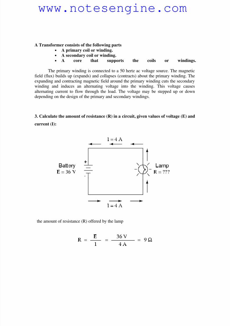
3. Calculate the amount of resistance (R) in a circuit, given values of voltage (E) and
current (I):
the amount of resistance (R) offered by the lamp
www.notesengine.com
8/6/2019 Anlaysis of Ciruits
http://slidepdf.com/reader/full/anlaysis-of-ciruits 10/41
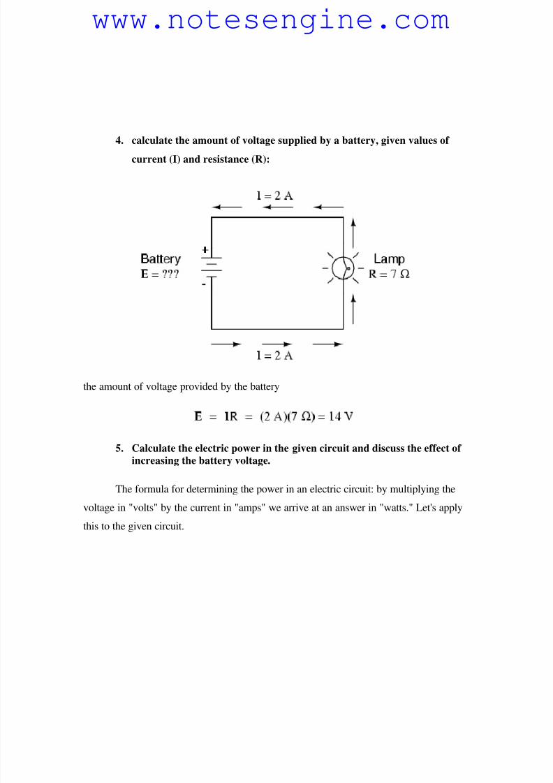
4. calculate the amount of voltage supplied by a battery, given values of
current (I) and resistance (R):
the amount of voltage provided by the battery
5. Calculate the electric power in the given circuit and discuss the effect of
increasing the battery voltage.
The formula for determining the power in an electric circuit: by multiplying the
voltage in "volts" by the current in "amps" we arrive at an answer in "watts." Let's apply
this to the given circuit.
www.notesengine.com
8/6/2019 Anlaysis of Ciruits
http://slidepdf.com/reader/full/anlaysis-of-ciruits 11/41
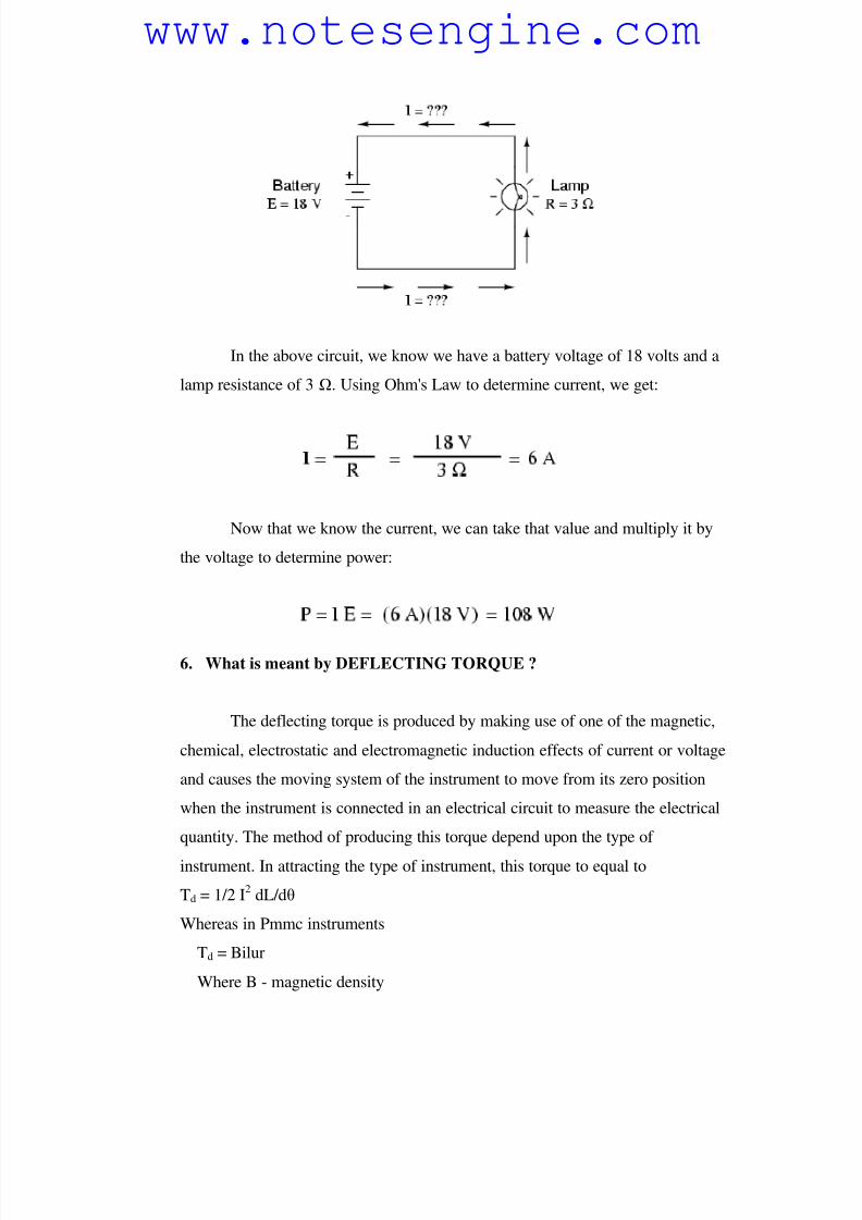
In the above circuit, we know we have a battery voltage of 18 volts and a
lamp resistance of 3 . Using Ohm's Law to determine current, we get:
Now that we know the current, we can take that value and multiply it by
the voltage to determine power:
6. What is meant by DEFLECTING TORQUE ?
The deflecting torque is produced by making use of one of the magnetic,
chemical, electrostatic and electromagnetic induction effects of current or voltage
and causes the moving system of the instrument to move from its zero position
when the instrument is connected in an electrical circuit to measure the electrical
quantity. The method of producing this torque depend upon the type of
instrument. In attracting the type of instrument, this torque to equal to
Td = 1/2 I2
dL/dθ
Whereas in Pmmc instruments
Td = Bilur
Where B - magnetic density
www.notesengine.com
8/6/2019 Anlaysis of Ciruits
http://slidepdf.com/reader/full/anlaysis-of-ciruits 12/41
i - current flowing
l - length of coil
u - number of turn
r - radius of coil
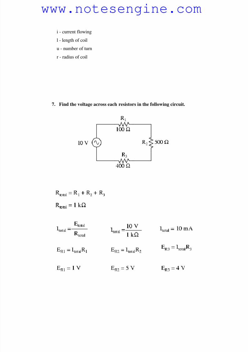
7. Find the voltage across each resistors in the following circuit.
www.notesengine.com
8/6/2019 Anlaysis of Ciruits
http://slidepdf.com/reader/full/anlaysis-of-ciruits 13/41
8. The effective resistance of two resistors connected in series is 100 .
When connected in parallel, then effective value in 24 ohm’s.
Determine the value of two resistors
Series R1+R2=100 => R2 =100 - R1
R1R2/R1+R2 = 24
R1R2/100 = 24
R1R2 =2400
R1 (100-R1) = 2400
100 R1-R1^2-2400 = 0
R1^2-100 R1 + 2400 = 0
(R1-60)(R1-40) = 0There Fore R1 = 60; R1 = 40
When R1 = 60 ; R2 = 100 – 60 = 40
When R1 = 40 ; R2 = 100 - 40 = 60
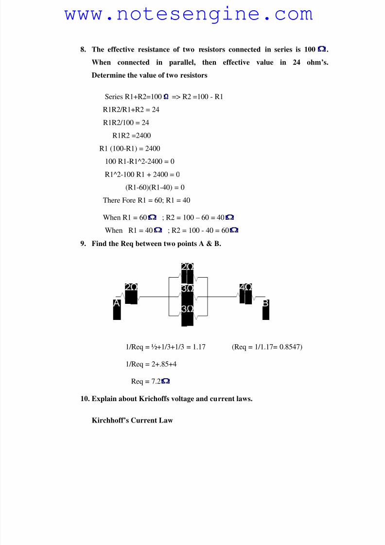
9. Find the Req between two points A & B.
1/Req = ½+1/3+1/3 = 1.17 (Req = 1/1.17= 0.8547)
1/Req = 2+.85+4
Req = 7.2
10. Explain about Krichoffs voltage and current laws.
Kirchhoff’s Current Law
www.notesengine.com
8/6/2019 Anlaysis of Ciruits
http://slidepdf.com/reader/full/anlaysis-of-ciruits 14/41
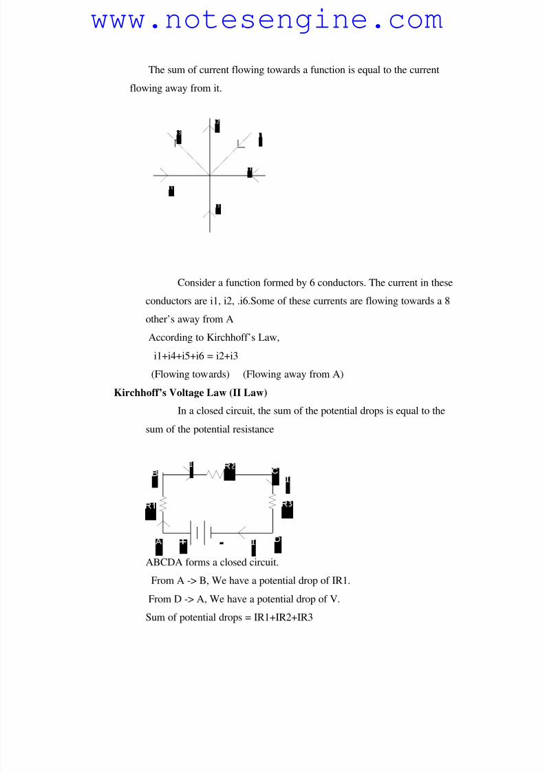
The sum of current flowing towards a function is equal to the current
flowing away from it.
Consider a function formed by 6 conductors. The current in these
conductors are i1, i2, .i6.Some of these currents are flowing towards a 8
other’s away from A
According to Kirchhoff’s Law,
i1+i4+i5+i6 = i2+i3
(Flowing towards) (Flowing away from A)
Kirchhoff’s Voltage Law (II Law)
In a closed circuit, the sum of the potential drops is equal to the
sum of the potential resistance
ABCDA forms a closed circuit.
From A -> B, We have a potential drop of IR1.
From D -> A, We have a potential drop of V.
Sum of potential drops = IR1+IR2+IR3
www.notesengine.com
8/6/2019 Anlaysis of Ciruits
http://slidepdf.com/reader/full/anlaysis-of-ciruits 15/41
Potential rise from D -> A =V
IR1+IR2+IR3 = V
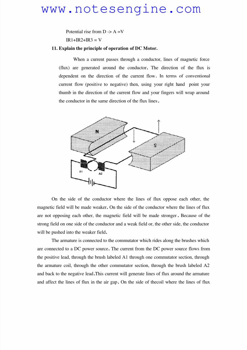
11. Explain the principle of operation of DC Motor.
When a current passes through a conductor, lines of magnetic force(flux) are generated around the conductor. The direction of the flux is
dependent on the direction of the current flow. In terms of conventional
current flow (positive to negative) then, using your right hand point your
thumb in the direction of the current flow and your fingers will wrap around
the conductor in the same direction of the flux lines.
On the side of the conductor where the lines of flux oppose each other, the
magnetic field will be made weaker. On the side of the conductor where the lines of flux
are not opposing each other, the magnetic field will be made stronger . Because of the
strong field on one side of the conductor and a weak field or, the other side, the conductor
will be pushed into the weaker field.
The armature is connected to the commutator which rides along the brushes which
are connected to a DC power source. The current from the DC power source flows from
the positive lead, through the brush labeled A1 through one commutator section, through
the armature coil, through the other commutator section, through the brush labeled A2
and back to the negative lead.This current will generate lines of flux around the armature
and affect the lines of flux in the air gap. On the side of thecoil where the lines of flux
www.notesengine.com
8/6/2019 Anlaysis of Ciruits
http://slidepdf.com/reader/full/anlaysis-of-ciruits 16/41
oppose each other, the magnetic field will be made weaker. On the side of the coil where
the lines of flux are riot opposing each other, the magnetic field is made stronger .
Because of the strong field on one side of the coil and the weak field on the other side,
the coil will be pushed into the weaker field and, because the armature coil is free to
rotate, it will rotate.
The torque available at the motor shaft (turning effort) is determined by the
magnetic force (flux) acting on the armature coil and the distance from the renter of
rotation that force is. The flux is determined by the current flowing through the armature
coil and strength of the field magnets.
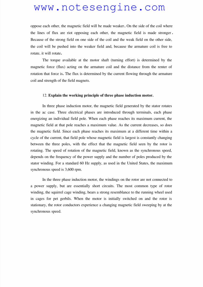
12. Explain the working principle of three phase induction motor.
In three phase induction motor, the magnetic field generated by the stator rotates
in the ac case. Three electrical phases are introduced through terminals, each phase
energizing an individual field pole. When each phase reaches its maximum current, the
magnetic field at that pole reaches a maximum value. As the current decreases, so does
the magnetic field. Since each phase reaches its maximum at a different time within a
cycle of the current, that field pole whose magnetic field is largest is constantly changing
between the three poles, with the effect that the magnetic field seen by the rotor is
rotating. The speed of rotation of the magnetic field, known as the synchronous speed,depends on the frequency of the power supply and the number of poles produced by the
stator winding. For a standard 60 Hz supply, as used in the United States, the maximum
synchronous speed is 3,600 rpm.
In the three phase induction motor, the windings on the rotor are not connected to
a power supply, but are essentially short circuits. The most common type of rotor
winding, the squirrel cage winding, bears a strong resemblance to the running wheel used
in cages for pet gerbils. When the motor is initially switched on and the rotor is
stationary, the rotor conductors experience a changing magnetic field sweeping by at the
synchronous speed.
www.notesengine.com
8/6/2019 Anlaysis of Ciruits
http://slidepdf.com/reader/full/anlaysis-of-ciruits 17/41
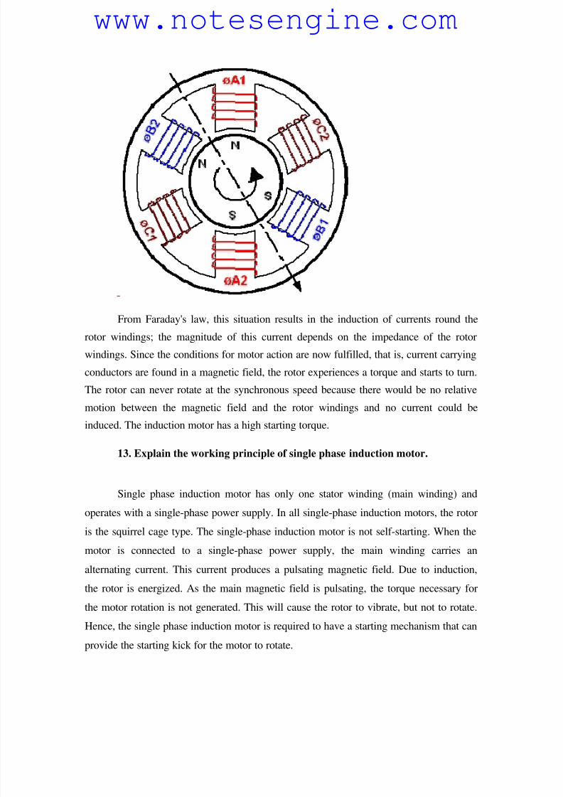
From Faraday's law, this situation results in the induction of currents round the
rotor windings; the magnitude of this current depends on the impedance of the rotor
windings. Since the conditions for motor action are now fulfilled, that is, current carrying
conductors are found in a magnetic field, the rotor experiences a torque and starts to turn.
The rotor can never rotate at the synchronous speed because there would be no relative
motion between the magnetic field and the rotor windings and no current could be
induced. The induction motor has a high starting torque.
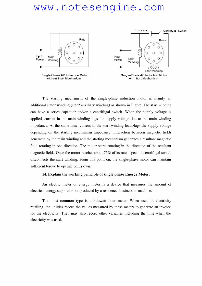
13. Explain the working principle of single phase induction motor.
Single phase induction motor has only one stator winding (main winding) and
operates with a single-phase power supply. In all single-phase induction motors, the rotor
is the squirrel cage type. The single-phase induction motor is not self-starting. When the
motor is connected to a single-phase power supply, the main winding carries an
alternating current. This current produces a pulsating magnetic field. Due to induction,
the rotor is energized. As the main magnetic field is pulsating, the torque necessary for
the motor rotation is not generated. This will cause the rotor to vibrate, but not to rotate.
Hence, the single phase induction motor is required to have a starting mechanism that can
provide the starting kick for the motor to rotate.
www.notesengine.com
8/6/2019 Anlaysis of Ciruits
http://slidepdf.com/reader/full/anlaysis-of-ciruits 18/41
The starting mechanism of the single-phase induction motor is mainly anadditional stator winding (start/ auxiliary winding) as shown in Figure. The start winding
can have a series capacitor and/or a centrifugal switch. When the supply voltage is
applied, current in the main winding lags the supply voltage due to the main winding
impedance. At the same time, current in the start winding leads/lags the supply voltage
depending on the starting mechanism impedance. Interaction between magnetic fields
generated by the main winding and the starting mechanism generates a resultant magnetic
field rotating in one direction. The motor starts rotating in the direction of the resultant
magnetic field. Once the motor reaches about 75% of its rated speed, a centrifugal switch
disconnects the start winding. From this point on, the single-phase motor can maintain
sufficient torque to operate on its own.
14. Explain the working principle of single phase Energy Meter.
An electric meter or energy meter is a device that measures the amount of
electrical energy supplied to or produced by a residence, business or machine.
The most common type is a kilowatt hour meter. When used in electricity
retailing, the utilities record the values measured by these meters to generate an invoice
for the electricity. They may also record other variables including the time when the
electricity was used.
www.notesengine.com
8/6/2019 Anlaysis of Ciruits
http://slidepdf.com/reader/full/anlaysis-of-ciruits 19/41
Modern electricity meters operate by continuously measuring the instantaneous
voltage (volts) and current (amperes) and finding the product of these to give
instantaneous electrical power (watts) which is then integrated against time to give
energy used (joules, kilowatt-hours etc). The meters fall into two basic categories,
electromechanical and electronic.
The energy meter operates by counting the revolutions of an aluminium disc
which is made to rotate at a speed proportional to the power. The number of revolutions
is thus proportional to the energy usage. It consumes a small amount of power, typically
around 2 watts.
The metallic disc is acted upon by two coils. One coil is connected in such a way
that it produces a magnetic flux in proportion to the voltage and the other produces a
magnetic flux in proportion to the current. The field of the voltage coil is delayed by 90
degrees using a lag coil. This produces eddy currents in the disc and the effect is such that
a force is exerted on the disc in proportion to the product of the instantaneous current and
voltage. A permanent magnet exerts an opposing force proportional to the speed of
rotation of the disc - this act as a brake which causes the disc to stop spinning when
power stops being drawn rather than allowing it to spin faster and faster. This causes the
disc to rotate at a speed proportional to the power being used.
The type of meter described above is used on a single-phase AC supply. Different
phase configurations use additional voltage and current coils.
The aluminium disc is supported by a spindle which has a worm gear which
drives the register. The register is a series of dials which record the amount of energy
used. The dials may be of the cyclometer type, an odometer-like display that is easy to
read where for each dial a single digit is shown through a window in the face of the
meter, or of the pointer type where a pointer indicates each digit. It should be noted that
with the dial pointer type, adjacent pointers generally rotate in opposite directions due tothe gearing mechanism.
www.notesengine.com
8/6/2019 Anlaysis of Ciruits
http://slidepdf.com/reader/full/anlaysis-of-ciruits 20/41
10 MARKS
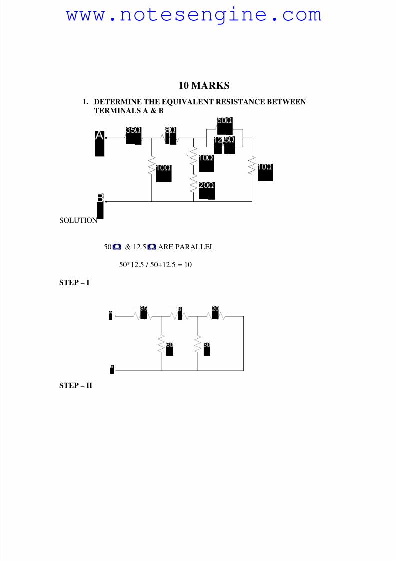
1. DETERMINE THE EQUIVALENT RESISTANCE BETWEEN
TERMINALS A & B
SOLUTION
50 & 12.5 ARE PARALLEL
50*12.5 / 50+12.5 = 10
STEP – I
STEP – II
www.notesengine.com
8/6/2019 Anlaysis of Ciruits
http://slidepdf.com/reader/full/anlaysis-of-ciruits 21/41
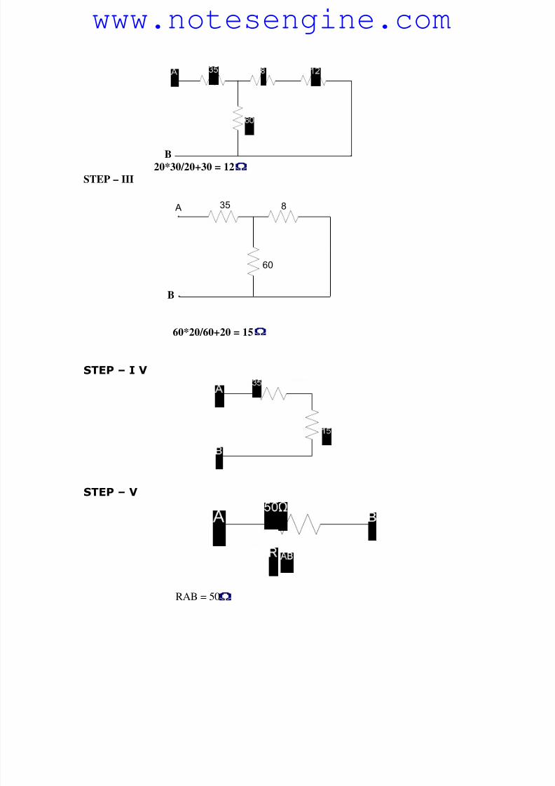
B
20*30/20+30 = 12
STEP – III
B
35 8
60
A
60*20/60+20 = 15
STEP – I V
STEP – V
RAB = 50
www.notesengine.com
8/6/2019 Anlaysis of Ciruits
http://slidepdf.com/reader/full/anlaysis-of-ciruits 22/41
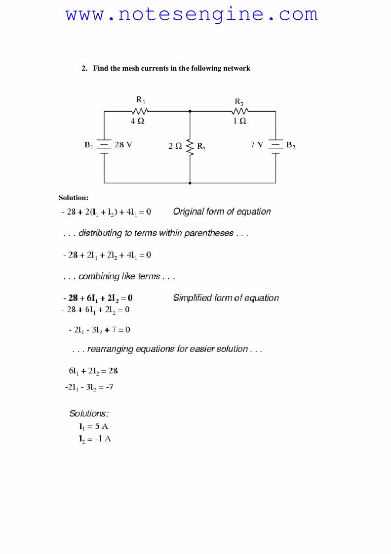
2. Find the mesh currents in the following network
Solution:
www.notesengine.com
8/6/2019 Anlaysis of Ciruits
http://slidepdf.com/reader/full/anlaysis-of-ciruits 23/41
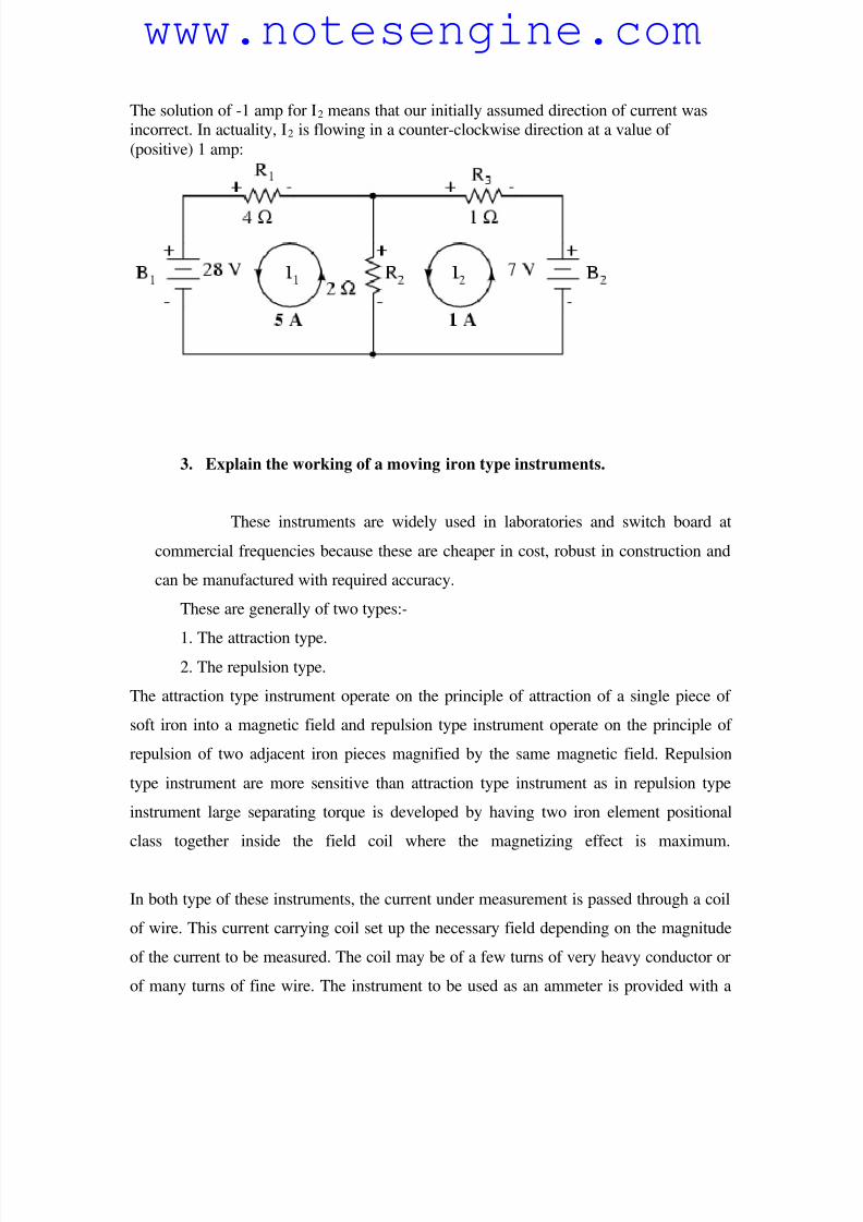
The solution of -1 amp for I2 means that our initially assumed direction of current wasincorrect. In actuality, I2 is flowing in a counter-clockwise direction at a value of
(positive) 1 amp:
3. Explain the working of a moving iron type instruments.
These instruments are widely used in laboratories and switch board at
commercial frequencies because these are cheaper in cost, robust in construction and
can be manufactured with required accuracy.
These are generally of two types:-
1. The attraction type.2. The repulsion type.
The attraction type instrument operate on the principle of attraction of a single piece of
soft iron into a magnetic field and repulsion type instrument operate on the principle of
repulsion of two adjacent iron pieces magnified by the same magnetic field. Repulsion
type instrument are more sensitive than attraction type instrument as in repulsion type
instrument large separating torque is developed by having two iron element positional
class together inside the field coil where the magnetizing effect is maximum.
In both type of these instruments, the current under measurement is passed through a coil
of wire. This current carrying coil set up the necessary field depending on the magnitude
of the current to be measured. The coil may be of a few turns of very heavy conductor or
of many turns of fine wire. The instrument to be used as an ammeter is provided with a
www.notesengine.com
8/6/2019 Anlaysis of Ciruits
http://slidepdf.com/reader/full/anlaysis-of-ciruits 24/41
coil of few turns of thick wire in order to have low resistance and carry large current and
that to be used as a voltameter is provided with a coil of large number of turns of wire in
order to have high resistance and draw as small current as possible.
4. Derive the expression for torque produced in moving iron instrument.
Let L be the self inductance corresponding to a total angular deflection of
q radians and change in inductance be dL correponding to small change in
deflection angel dq due to small change in current.
The change in energy of magnetic field,
dw = Td dθ
Since change in energy dE = workdone, dw
Td dθ = ½ I2dL
Td = ½ I2dL/dθ
where I is in amperes, L is in Henry and θ is in Radians.
Thus toruqe is proportional to the square of the instrument current and to the rate
of change of inductance with deflection.
5. An energy meter revolves 10 revolutions of disc for unit of energy. Find
the number of revolutions made by it during an hour when connected
across when connected 20A at 210V and 0.8 power factor leading. If
energy meter revolves 350 revolutions, find the % error.
Answer.
Energy consumed in one hour = VI cos φ / 1000
= 210 x 20 x 0.8 / 1000
= 3.360 kwh.
The number of revolution the meter should make it is correct = 3.360 x
www.notesengine.com
8/6/2019 Anlaysis of Ciruits
http://slidepdf.com/reader/full/anlaysis-of-ciruits 25/41
registration const in revolution per kwh
= 3.360 x 100
= 336
Number of revolution actually made = 350
% error = (350-336) x 100 / 350
% error = 0.1466 %
6. Explain how following torque are produced in pmmc instrument and
attracted type moving iron instruments
1. Deflecting torque
2. Control torque
3. Damping torque
1. DEFLECTING TORQUE:- The deflecting torque is produced by making
use of one of the magnetic, chemical, electrostatic and electromagnetic
induction effects of current or voltage and causes the moving system of the
instrument to move from its zero position when the instrument is connected in
an electrical circuit to measure the electrical quantity. The method of
producing this torque depend upon the type of instrument. In attracting the
type of instrument, this torque to equal to
Td = 1/2 I2 dL/dθ
Whereas in Pmmc instruments
Td = Bilur
Where B - magnetic density
i - current flowing
l - length of coil
u - number of turn
r - radius of coil
2. CONTROLLING TORQUE:- The magnitude of the movement to the
moving system would be somewhat indefinite under the influence of
deflecting torque unless some controlling torque exist. This torque opposes
www.notesengine.com
8/6/2019 Anlaysis of Ciruits
http://slidepdf.com/reader/full/anlaysis-of-ciruits 26/41
the deflecting torque and increases with increase in deflection of the moving
system without controlling system the irrespective magnitude of current and
moreover, once deflected it would not return to its zero position on removing
the current.
In attraction type instrument it is produced by spring control and in PMMC
too it would be produced by spring control.
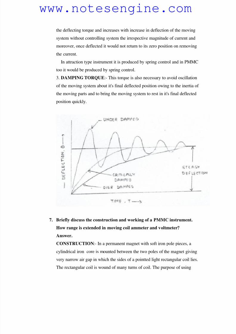
3. DAMPING TORQUE:- This torque is also necessary to avoid oscillation
of the moving system about it's final deflected position owing to the inertia of
the moving parts and to bring the moving system to rest in it's final deflected
position quickly.
7. Briefly discuss the construction and working of a PMMC instrument.
How range is extended in moving coil ammeter and voltmeter?
Answer.
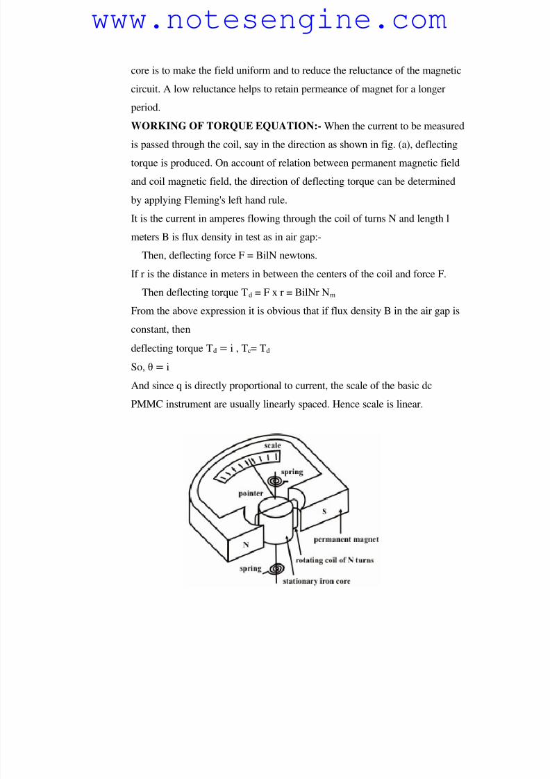
CONSTRUCTION:- In a permanent magnet with soft iron pole pieces, a
cylindrical iron core is mounted between the two poles of the magnet giving
very narrow air gap in which the sides of a pointted light rectangular coil lies.
The rectangular coil is wound of many turns of coil. The purpose of using
www.notesengine.com
8/6/2019 Anlaysis of Ciruits
http://slidepdf.com/reader/full/anlaysis-of-ciruits 27/41
core is to make the field uniform and to reduce the reluctance of the magnetic
circuit. A low reluctance helps to retain permeance of magnet for a longer
period.
WORKING OF TORQUE EQUATION:- When the current to be measured
is passed through the coil, say in the direction as shown in fig. (a), deflecting
torque is produced. On account of relation between permanent magnetic field
and coil magnetic field, the direction of deflecting torque can be determined
by applying Fleming's left hand rule.
It is the current in amperes flowing through the coil of turns N and length l
meters B is flux density in test as in air gap:-
Then, deflecting force F = BilN newtons.
If r is the distance in meters in between the centers of the coil and force F.
Then deflecting torque Td = F x r = BilNr Nm
From the above expression it is obvious that if flux density B in the air gap is
constant, then
deflecting torque Td = i , Tc= Td
So, θ = i
And since q is directly proportional to current, the scale of the basic dc
PMMC instrument are usually linearly spaced. Hence scale is linear.
www.notesengine.com
8/6/2019 Anlaysis of Ciruits
http://slidepdf.com/reader/full/anlaysis-of-ciruits 28/41
8. Discuss the construction and working of an electrodynamic wattmeter
with the help of diagram?
Answer.
This type of instrument is similar in design and principle to the dynanometer
type ammeter and voltameter.
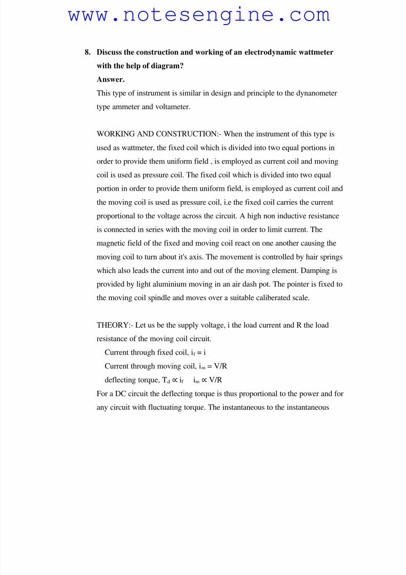
WORKING AND CONSTRUCTION:- When the instrument of this type is
used as wattmeter, the fixed coil which is divided into two equal portions in
order to provide them uniform field , is employed as current coil and moving
coil is used as pressure coil. The fixed coil which is divided into two equal
portion in order to provide them uniform field, is employed as current coil and
the moving coil is used as pressure coil, i.e the fixed coil carries the current
proportional to the voltage across the circuit. A high non inductive resistance
is connected in series with the moving coil in order to limit current. The
magnetic field of the fixed and moving coil react on one another causing the
moving coil to turn about it's axis. The movement is controlled by hair springs
which also leads the current into and out of the moving element. Damping is
provided by light aluminium moving in an air dash pot. The pointer is fixed to
the moving coil spindle and moves over a suitable caliberated scale.
THEORY:- Let us be the supply voltage, i the load current and R the load
resistance of the moving coil circuit.
Current through fixed coil, if = i
Current through moving coil, im = V/R
deflecting torque, Td ∝ if im ∝ V/R
For a DC circuit the deflecting torque is thus proportional to the power and for
any circuit with fluctuating torque. The instantaneous to the instantaneous
www.notesengine.com
8/6/2019 Anlaysis of Ciruits
http://slidepdf.com/reader/full/anlaysis-of-ciruits 29/41
power.
9. Compare merits and demerits of moving iron type instruments and
dynamometer type instruments. Which one is superior why?
Answer.
1. TORQUE HEIGHT RATIO:- Dynamometer type instruments have equal small
torque height ratio.
2. FRICTION ERROR:- Dynamometer type instruments have considerable
friction error.
3. FRICTION LOSS:- Owing to heavy moving system, dynamometer type
instruments have more friction losses.
4. COST AND SENSITIVITY TO OVERLOAD:- As a result of measures to
reduce the frictional error, the dynamometer type instruments are more sensitive
to overloads and mechanical impactsis in comparison to moving iron type
instruments.
www.notesengine.com
8/6/2019 Anlaysis of Ciruits
http://slidepdf.com/reader/full/anlaysis-of-ciruits 30/41
5. SENSTIVITY:- The senstivity of dynamometer instrument is typically very
poor due to poor deflecting torque.
6. POWER CONSUMPTION:- Dynamometer type instrument have
comparatively higher power consumption.
7. EFFECT OF STRAY MAGNETIC FIELD:- There is no effect of stray
magnetic field on moving iron type while dynamometer type are most sensitive
towards it.
8. HYSTERISIS AND EDDY CURRENT ERRORS:- Dynamometer type
instruments are free from these erors while moving iron have these errors.
9. EFFECT OF WAVE FORM:- Dynamometer type instruments are very useful
for accurate measurement of runs voltage while frequency change serious e rrors
in AC measurement in moving iron type instruments.
10. CALIBRATION:- Dynamometer type instruments have same calibration for
AC and DC measurements while moving iron type have a difference between AC
and DC calibration.
10. Why shunt is usually used voltmeter and ammeter? A moving coil
instrument has a resistance of 5 and gives full deflection of 100mv.
Show how the instrument may be used to measure:-
1. voltage upto 50V
2. current upto 10A
Answer.
Shunt is usually used in voltmeter and ammeter to extend the range of
voltmeter and ammeters.
www.notesengine.com
8/6/2019 Anlaysis of Ciruits
http://slidepdf.com/reader/full/anlaysis-of-ciruits 31/41
Rm = 5
Vm = 100mv
Im = Vm /Rm = 100mv/5 = 20mA
1. For measuring voltage upto 50V.
Series resistance is used with the instrument whose resistance is
R = V/Im - Rm = 50/(20 x 10-3
) - 5
R = 2.5 x 10⁻³
- 5 = R = 2495
2. Such resistance of resistance Rf is used to be connected
Rf = Rm /[I/Im - 1]
= 5/[10/20 x 10-3
-1] = 5 x 2/998
Rf = 0.01002004
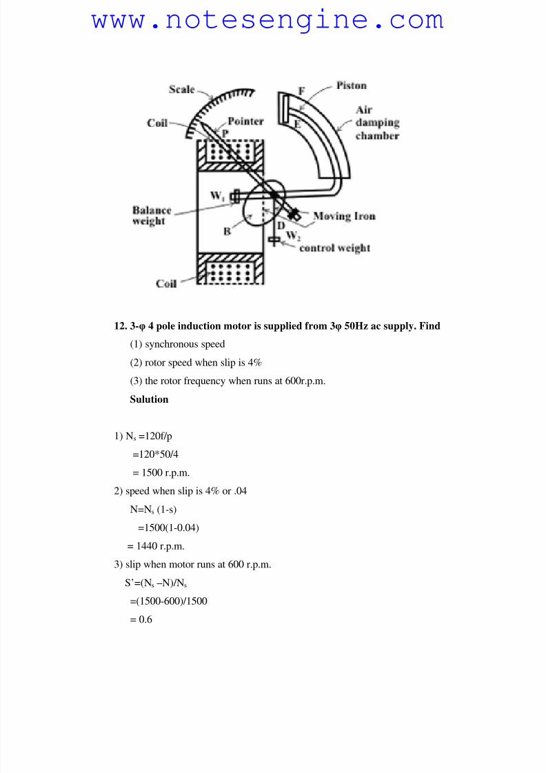
11. Explain the principle of operation of attraction type moving iron
instruments and explain how the controlling and damping forces are
obtained?
Answer. The earliest and simplest form of attraction moving iron instruments
uses a solenoid and moving oval shaped soft iron pinoted eccentrically. To
this iron a pointer is attached so that it may deflect along with the moving iron
over a graduate scale. The iron is made of sheet metal specially shaped to give
a scale as nearby uniform as possible. The moving iron is drawn into field of
solenoid when current flows through it. The movement of the iron always
from weaker magnetic field outside the coil into the stronger field inside the
coil regardless the direction of flow of current. When the current to be
measured is passed through the solenoid, a magnetic field is set up inside the
solenoid, which in turn magnetises the iron. Thus the iron is attached into the
coil causing the spindle and the pointer to rotate.
So much instruments normally have spring control and pneumatic damping
forces.
www.notesengine.com
8/6/2019 Anlaysis of Ciruits
http://slidepdf.com/reader/full/anlaysis-of-ciruits 32/41
12. 3-φ 4 pole induction motor is supplied from 3φ 50Hz ac supply. Find
(1) synchronous speed
(2) rotor speed when slip is 4%
(3) the rotor frequency when runs at 600r.p.m.
Sulution
1) Ns =120f/p
=120*50/4
= 1500 r.p.m.
2) speed when slip is 4% or .04
N=Ns (1-s)
=1500(1-0.04)
= 1440 r.p.m.
3) slip when motor runs at 600 r.p.m.
S’=(Ns –N)/Ns
=(1500-600)/1500
= 0.6
www.notesengine.com
8/6/2019 Anlaysis of Ciruits
http://slidepdf.com/reader/full/anlaysis-of-ciruits 33/41
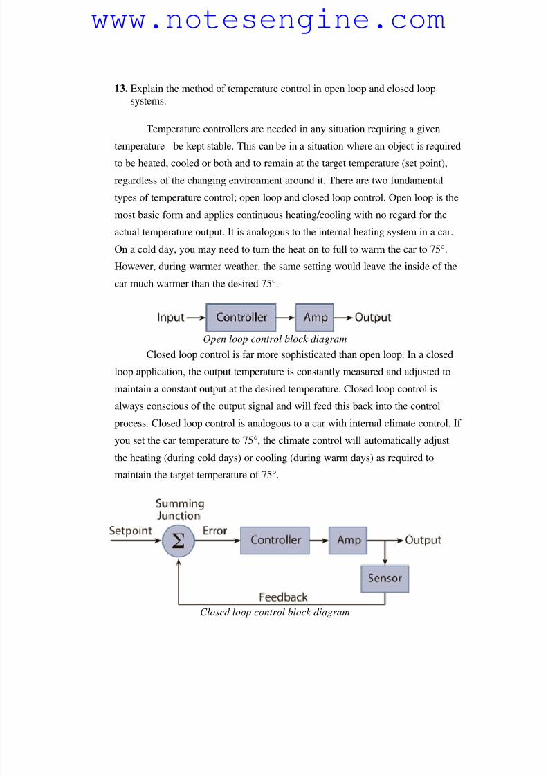
13. Explain the method of temperature control in open loop and closed loop
systems.
Temperature controllers are needed in any situation requiring a given
temperature be kept stable. This can be in a situation where an object is required
to be heated, cooled or both and to remain at the target temperature (set point),
regardless of the changing environment around it. There are two fundamental
types of temperature control; open loop and closed loop control. Open loop is the
most basic form and applies continuous heating/cooling with no regard for the
actual temperature output. It is analogous to the internal heating system in a car.
On a cold day, you may need to turn the heat on to full to warm the car to 75°.
However, during warmer weather, the same setting would leave the inside of thecar much warmer than the desired 75°.
Open loop control block diagram
Closed loop control is far more sophisticated than open loop. In a closed
loop application, the output temperature is constantly measured and adjusted to
maintain a constant output at the desired temperature. Closed loop control is
always conscious of the output signal and will feed this back into the controlprocess. Closed loop control is analogous to a car with internal climate control. If
you set the car temperature to 75°, the climate control will automatically adjust
the heating (during cold days) or cooling (during warm days) as required to
maintain the target temperature of 75°.
Closed loop control block diagram
www.notesengine.com
8/6/2019 Anlaysis of Ciruits
http://slidepdf.com/reader/full/anlaysis-of-ciruits 34/41
A temperature controller is a device used to hold a desired temperature at a
specified value. The simplest example of a temperature controller is a common
thermostat found in homes. For instance, a hot water heater uses a thermostat to control
the temperature of the water and maintain it at a certain commanded temperature.
Temperature controllers are also used in ovens. When a temperature is set for an oven, a
controller monitors the actual temperature inside of the oven. If it falls below the set
temperature, it sends a signal to activate the heater to raise the temperature back to the set
point. Thermostats are also used in refrigerators. So if the temperature gets too high, a
controller initiates an action to bring the temperature down.
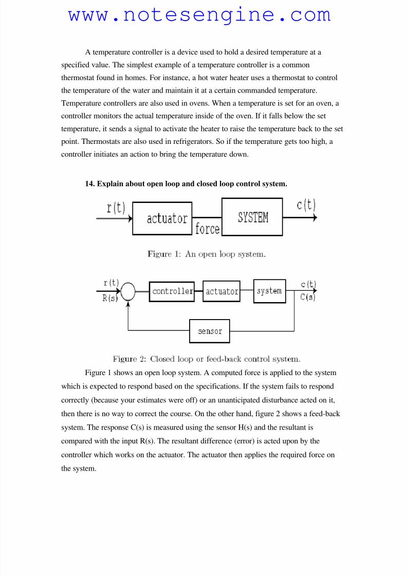
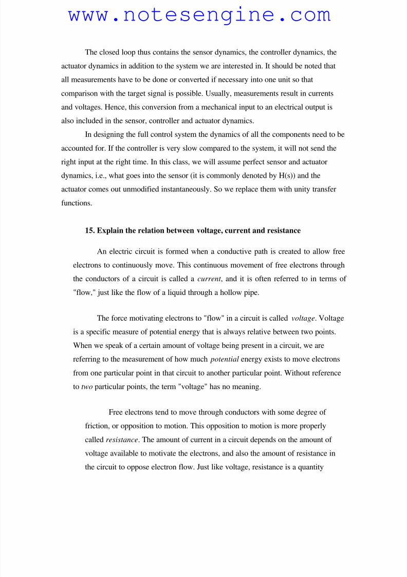
14. Explain about open loop and closed loop control system.
Figure 1 shows an open loop system. A computed force is applied to the system
which is expected to respond based on the specifications. If the system fails to respond
correctly (because your estimates were off) or an unanticipated disturbance acted on it,then there is no way to correct the course. On the other hand, figure 2 shows a feed-back
system. The response C(s) is measured using the sensor H(s) and the resultant is
compared with the input R(s). The resultant difference (error) is acted upon by the
controller which works on the actuator. The actuator then applies the required force on
the system.
www.notesengine.com
8/6/2019 Anlaysis of Ciruits
http://slidepdf.com/reader/full/anlaysis-of-ciruits 35/41
The closed loop thus contains the sensor dynamics, the controller dynamics, the
actuator dynamics in addition to the system we are interested in. It should be noted that
all measurements have to be done or converted if necessary into one unit so that
comparison with the target signal is possible. Usually, measurements result in currents
and voltages. Hence, this conversion from a mechanical input to an electrical output is
also included in the sensor, controller and actuator dynamics.
In designing the full control system the dynamics of all the components need to be
accounted for. If the controller is very slow compared to the system, it will not send the
right input at the right time. In this class, we will assume perfect sensor and actuator
dynamics, i.e., what goes into the sensor (it is commonly denoted by H(s)) and the
actuator comes out unmodified instantaneously. So we replace them with unity transfer
functions.
15. Explain the relation between voltage, current and resistance
An electric circuit is formed when a conductive path is created to allow free
electrons to continuously move. This continuous movement of free electrons through
the conductors of a circuit is called a current , and it is often referred to in terms of
"flow," just like the flow of a liquid through a hollow pipe.
The force motivating electrons to "flow" in a circuit is called voltage. Voltage
is a specific measure of potential energy that is always relative between two points.
When we speak of a certain amount of voltage being present in a circuit, we are
referring to the measurement of how much potential energy exists to move electrons
from one particular point in that circuit to another particular point. Without reference
to two particular points, the term "voltage" has no meaning.
Free electrons tend to move through conductors with some degree of
friction, or opposition to motion. This opposition to motion is more properly
called resistance. The amount of current in a circuit depends on the amount of
voltage available to motivate the electrons, and also the amount of resistance in
the circuit to oppose electron flow. Just like voltage, resistance is a quantity
www.notesengine.com
8/6/2019 Anlaysis of Ciruits
http://slidepdf.com/reader/full/anlaysis-of-ciruits 36/41
relative between two points. For this reason, the quantities of voltage and
resistance are often stated as being "between" or "across" two points in a circuit.
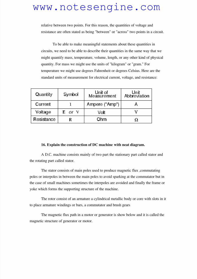
To be able to make meaningful statements about these quantities in
circuits, we need to be able to describe their quantities in the same way that we
might quantify mass, temperature, volume, length, or any other kind of physical
quantity. For mass we might use the units of "kilogram" or "gram." For
temperature we might use degrees Fahrenheit or degrees Celsius. Here are the
standard units of measurement for electrical current, voltage, and resistance:
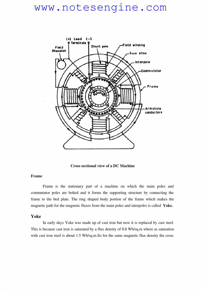
16. Explain the construction of DC machine with neat diagram.
A D.C. machine consists mainly of two part the stationary part called stator and
the rotating part called stator.
The stator consists of main poles used to produce magnetic flux ,commutating
poles or interpoles in between the main poles to avoid sparking at the commutator but in
the case of small machines sometimes the interpoles are avoided and finally the frame or
yoke which forms the supporting structure of the machine.
The rotor consist of an armature a cylindrical metallic body or core with slots in it
to place armature windings or bars, a commutator and brush gears
The magnetic flux path in a motor or generator is show below and it is called the
magnetic structure of generator or motor.
www.notesengine.com
8/6/2019 Anlaysis of Ciruits
http://slidepdf.com/reader/full/anlaysis-of-ciruits 37/41
Cross sectional view of a DC Machine
Frame
Frame is the stationary part of a machine on which the main poles and
commutator poles are bolted and it forms the supporting structure by connecting the
frame to the bed plate. The ring shaped body portion of the frame which makes the
magnetic path for the magnetic fluxes from the main poles and interpoles is called Yoke.
Yoke
In early days Yoke was made up of cast iron but now it is replaced by cast steel.
This is because cast iron is saturated by a flux density of 0.8 Wb/sq.m where as saturation
with cast iron steel is about 1.5 Wb/sq.m.So for the same magnetic flux density the cross
www.notesengine.com
8/6/2019 Anlaysis of Ciruits
http://slidepdf.com/reader/full/anlaysis-of-ciruits 38/41
section area needed for cast steel is less than cast iron hence the weight of the machine
too. If we use cast iron there may be chances of blow holes in it while casting. so now
rolled steels are developed and these have consistent magnetic and mechanical properties.
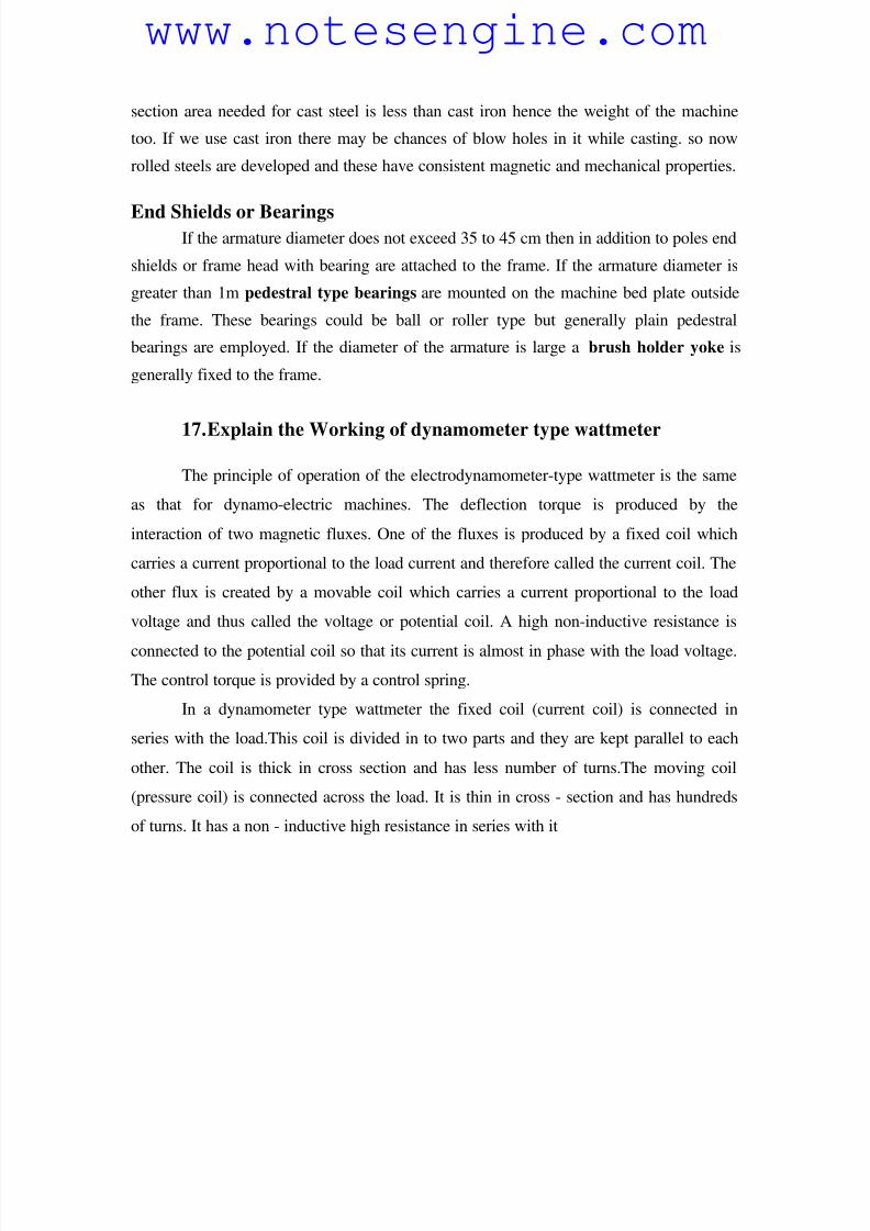
End Shields or BearingsIf the armature diameter does not exceed 35 to 45 cm then in addition to poles end
shields or frame head with bearing are attached to the frame. If the armature diameter is
greater than 1m pedestral type bearings are mounted on the machine bed plate outside
the frame. These bearings could be ball or roller type but generally plain pedestral
bearings are employed. If the diameter of the armature is large a brush holder yoke is
generally fixed to the frame.
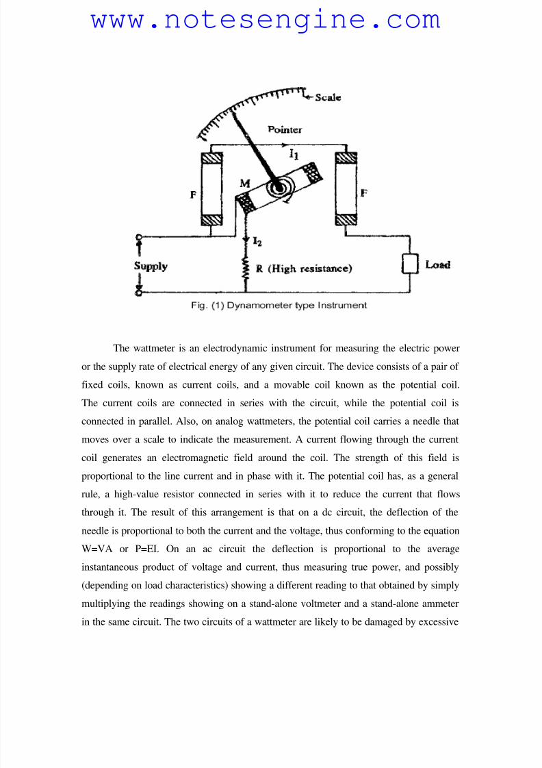
17. Explain the Working of dynamometer type wattmeter
The principle of operation of the electrodynamometer-type wattmeter is the same
as that for dynamo-electric machines. The deflection torque is produced by the
interaction of two magnetic fluxes. One of the fluxes is produced by a fixed coil which
carries a current proportional to the load current and therefore called the current coil. The
other flux is created by a movable coil which carries a current proportional to the load
voltage and thus called the voltage or potential coil. A high non-inductive resistance is
connected to the potential coil so that its current is almost in phase with the load voltage.
The control torque is provided by a control spring.
In a dynamometer type wattmeter the fixed coil (current coil) is connected in
series with the load.This coil is divided in to two parts and they are kept parallel to each
other. The coil is thick in cross section and has less number of turns.The moving coil
(pressure coil) is connected across the load. It is thin in cross - section and has hundreds
of turns. It has a non - inductive high resistance in series with it
www.notesengine.com
8/6/2019 Anlaysis of Ciruits
http://slidepdf.com/reader/full/anlaysis-of-ciruits 39/41
The wattmeter is an electrodynamic instrument for measuring the electric power
or the supply rate of electrical energy of any given circuit. The device consists of a pair of
fixed coils, known as current coils, and a movable coil known as the potential coil.
The current coils are connected in series with the circuit, while the potential coil is
connected in parallel. Also, on analog wattmeters, the potential coil carries a needle that
moves over a scale to indicate the measurement. A current flowing through the current
coil generates an electromagnetic field around the coil. The strength of this field is
proportional to the line current and in phase with it. The potential coil has, as a general
rule, a high-value resistor connected in series with it to reduce the current that flows
through it. The result of this arrangement is that on a dc circuit, the deflection of the
needle is proportional to both the current and the voltage, thus conforming to the equation
W=VA or P=EI. On an ac circuit the deflection is proportional to the average
instantaneous product of voltage and current, thus measuring true power, and possibly
(depending on load characteristics) showing a different reading to that obtained by simply
multiplying the readings showing on a stand-alone voltmeter and a stand-alone ammeter
in the same circuit. The two circuits of a wattmeter are likely to be damaged by excessive
www.notesengine.com
8/6/2019 Anlaysis of Ciruits
http://slidepdf.com/reader/full/anlaysis-of-ciruits 40/41
current. The ammeter and voltmeter are both vulnerable to overheating - in case of an
overload, their pointers will be driven off scale - but in the wattmeter, either or even both
the current and potential circuits can overheat without the pointer approaching the end of
the scale! This is because the position of the pointer depends on the power factor, voltage
and current. Thus, a circuit with a low power factor will give a low reading on the
wattmeter, even when both of its circuits are loaded to the maximum safety limit.
Therefore, a wattmeter is rated not only in watts, but also in volts and amperes.
18. Explain the construction of transformer with neat diagram.
A transformer is an electrical device used to convert AC power at a certain
voltage level to AC power at a different voltage, but at the same frequency.
The construction of a transformer includes a ferromagnetic core around which
multiple coils, or windings, of wire are wrapped. The input line connects to the 'primary'
coil, while the output lines connect to 'secondary' coils. The alternating current in the
primary coil induces an alternating magnetic flux that 'flows' around the ferromagnetic
core, changing direction during each electrical cycle. The alternating flux in the core in
turn induces an alternating current in each of the secondary coils. The voltage at each of
the secondary coils is directly related to the primary voltage by the turns ratio, or the
number of turns in the primary coil divided by the number turns in the secondary coil.
For instance, if the primary coil consists of 100 turns and carries 480 volts and a
secondary coil consists of 25 turns, the secondary voltage is then:
secondary voltage = (480 volts) * (25/100) = 120 volts
Two coils of wire (called windings) are wound on some type of core material. In
some cases the coils of wire are wound on a cylindrical or rectangular cardboard form. In
effect, the core material is air and the transformer is called an AIR-CORE
TRANSFORMER. Transformers used at low frequencies, such as 50 hertz and 400 hertz,
require a core of low-reluctance magnetic material, usually iron. This type of transformer
is called an IRON-CORE TRANSFORMER. Most power transformers are of the iron-
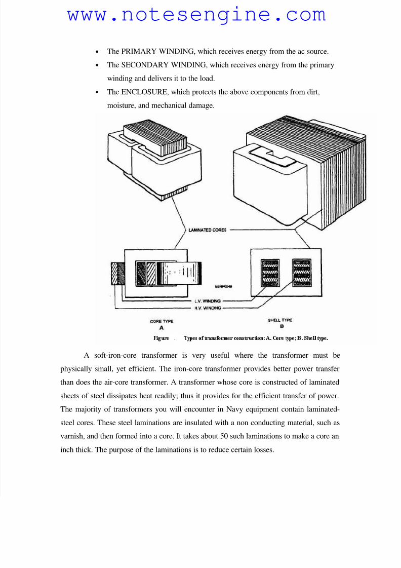
core type. The principle parts of a transformer and their functions are:
• The CORE, which provides a path for the magnetic lines of flux.
www.notesengine.com
8/6/2019 Anlaysis of Ciruits
http://slidepdf.com/reader/full/anlaysis-of-ciruits 41/41
• The PRIMARY WINDING, which receives energy from the ac source.
• The SECONDARY WINDING, which receives energy from the primary
winding and delivers it to the load.
• The ENCLOSURE, which protects the above components from dirt,
moisture, and mechanical damage.
A soft-iron-core transformer is very useful where the transformer must be
physically small, yet efficient. The iron-core transformer provides better power transfer
than does the air-core transformer. A transformer whose core is constructed of laminated
sheets of steel dissipates heat readily; thus it provides for the efficient transfer of power.The majority of transformers you will encounter in Navy equipment contain laminated-
steel cores. These steel laminations are insulated with a non conducting material, such as
varnish, and then formed into a core. It takes about 50 such laminations to make a core an
inch thick. The purpose of the laminations is to reduce certain losses.
www.notesengine.com