Embed Size (px)
Citation preview
Subject to technical alterations.
ANDREAS MAIER FELLBACH ∙ www.amf.de Hydraulic clamping SyStemS 141
About hydraulic multiple-clamping systems
... AND THEIR SPECIFIC CHARACTERISTICS:
> Hydraulic precision multiple-clamping system, symmetrical layout, with four clamping points. Individually adjustable.
Centrically clamping.
> Manual adjustment of clamping intervals with a pitch of 1 mm. Positive-fit connection. The use of the full clamping stroke
of 3 mm allows the clamping of workpieces with nominal widths from 13 mm to 134 mm. With a clamping stroke of 1 mm, a
max. nominal workpiece width of 136 mm can be clamped. Please note: Gripping jaws change these values!
> Workpiece support surface = 104 x 6 mm, workpiece clamping surface = 104 x 12 mm. The workpiece supports are
integrated in the clamping jaws and cylinder housings.
> jaw width = 104 mm
> Oil is supplied centrally, optionally through two lateral connections in G 1/4 or through O-ring connections in the base plate.
Oil f low is distributed evenly to the pistons via the pipe system.
> For use on machine tables as well as in devices and quick-change systems.
NOTE:> Maximum traversing speed 0.5 m/s.
> Minimum operating pressure 40 bar.
> The use of a hydraulic unit with a 4/3-way valve is recommended.
> To manually adjust the clamping positions, the A and B channels must be connected to the tank (unpressurized state).
> When programming the machines, please observe the zero offset on the multiple clamping system!!
APPLICATION:> Two or four workpieces on a centrally clamping device.
> Parallel arrangement of several devices for series production.
> Parallel arrangement of several devices for long workpieces.
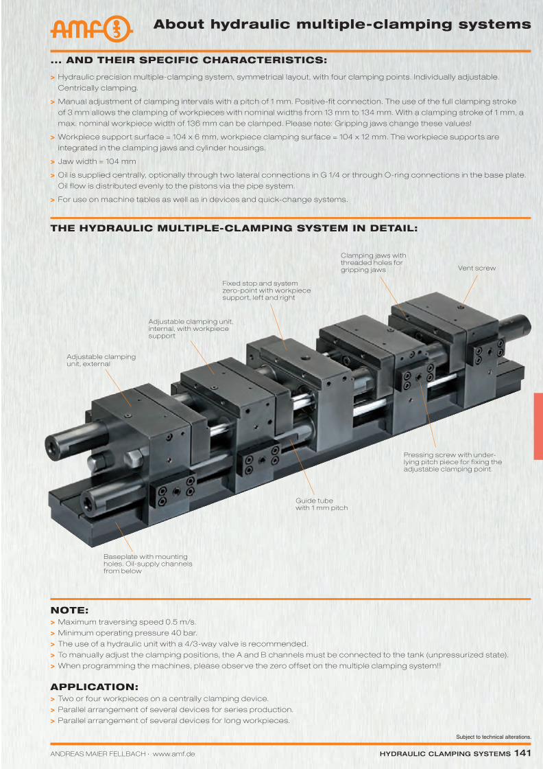
Fixed stop and system zero-point with workpiece support, lef t and right
Clamping jaws with threaded holes for gripping jaws
Adjustable clamping unit, internal, with workpiece support
Guide tube with 1 mm pitch
Baseplate with mounting holes. Oil-supply channels from below
Vent screw
Pressing screw with under-lying pitch piece for f ixing the adjustable clamping point.
Adjustable clamping unit, external
THE HYDRAULIC MULTIPLE-CLAMPING SYSTEM IN DETAIL:
Katalog_2012_Hydraulik_EN_ohnePreise.indd 141 3/28/2013 8:35:03 AM
Subject to technical alterations.
142 Hydraulic clamping SyStemS ANDREAS MAIER FELLBACH ∙ www.amf.de
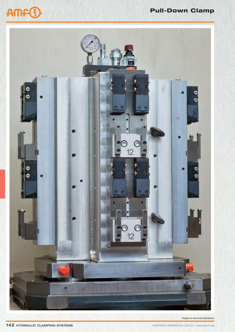
Pull-Down Clamp
Katalog_2012_Hydraulik_EN_ohnePreise.indd 142 3/28/2013 8:35:06 AM
Subject to technical alterations.
ANDREAS MAIER FELLBACH ∙ www.amf.de Hydraulic clamping SyStemS 143
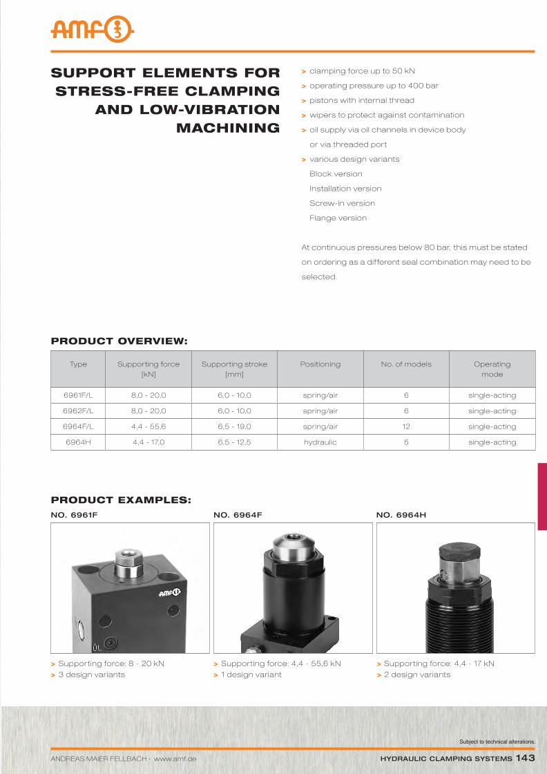
PRODUCT ExAMPLES:
no. 6961F no. 6964F no. 6964H
PRODUCT OVERVIEW:
Type Supporting force [kN]
Supporting stroke [mm]
Positioning No. of models Operating mode
6961F/L 8,0 - 20,0 6,0 - 10,0 spring/air 6 single-acting
6962F/L 8,0 - 20,0 6,0 - 10,0 spring/air 6 single-acting
6964F/L 4,4 - 55,6 6,5 - 19,0 spring/air 12 single-acting
6964H 4,4 - 17,0 6,5 - 12,5 hydraulic 5 single-acting
> clamping force up to 50 kN
> operating pressure up to 400 bar
> pistons with internal thread
> wipers to protect against contamination
> oil supply via oil channels in device body
or via threaded port
> various design variants
Block version
Installation version
Screw-in version
Flange version
At continuous pressures below 80 bar, this must be stated
on ordering as a dif ferent seal combination may need to be
selected.
SUPPORT ELEMENTS FOR STRESS-FREE CLAMPING
AND LOW-VIbRATION MACHINING
> Supporting force: 8 - 20 kN
> 3 design variants
> Supporting force: 4,4 - 55,6 kN
> 1 design variant
> Supporting force: 4,4 - 17 kN
> 2 design variants
Katalog_2012_Hydraulik_EN_ohnePreise.indd 143 3/28/2013 8:35:06 AM
144 Hydraulic clamping SyStemS ANDREAS MAIER FELLBACH ∙ www.amf.de
Subject to technical alterations.
Support Element
Wiring diagrams:Fig. 1
Fig. 2
Diagram:
0.004 mm/kN elastic change in length under load.
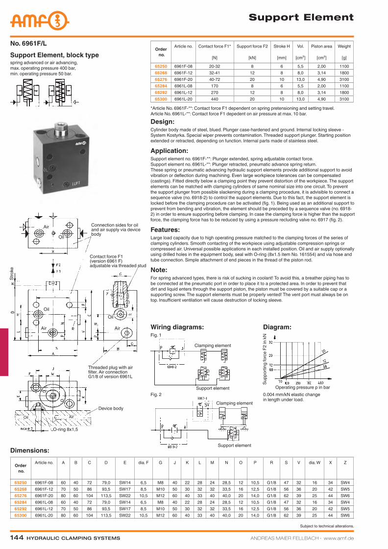
spring advanced or air advancing, max. operating pressure 400 bar, min. operating pressure 50 bar.
Support Element, block typeNo. 6961F/L
Order no.
Article no. Contact force F1*
[N]
Support force F2
[kN]
Stroke H
[mm]
Vol.
[cm³]
Piston area
[cm²]
Weight
[g]
65250 6961F-08 20-32 8 6 5,5 2,00 110065268 6961F-12 32-41 12 8 8,0 3,14 180065276 6961F-20 40-72 20 10 13,0 4,90 310065284 6961L-08 170 8 6 5,5 2,00 110065292 6961L-12 270 12 8 8,0 3,14 180065300 6961L-20 440 20 10 13,0 4,90 3100
Design:Cylinder body made of steel, blued. Plunger case-hardened and ground. Internal locking sleeve - System Kostyrka. Special wiper prevents contamination. Threaded support plunger. Starting position extended or retracted, depending on function. Internal parts made of stainless steel.
Application:Support element no. 6961F-**: Plunger extended, spring adjustable contact force. Support element no. 6961L-**: Plunger retracted, pneumatic advance spring return. These spring or pneumatic advancing hydraulic support elements provide additional support to avoid vibration or deflection during machining. Even large workpiece tolerances can be compensated (castings). Fitted directly below a clamping point they prevent distortion of the workpiece. The support elements can be matched with clamping cylinders of same nominal size into one circuit. To prevent the support plunger from possible slackening during a clamping procedure, it is advisible to connect a sequence valve (no. 6918-2) to control the support elements. Due to this fact, the support element is locked before the clamping procedure can be activated (fig. 1). Being used as an additional support to prevent from bending and vibration, the element should be preceded by a sequence valve (no. 6918-2) in order to ensure supporting before clamping. In case the clamping force is higher than the support force, the clamping force has to be reduced by using a pressure recluding valve no. 6917 (fig. 2).
Features:Large load capacity due to high operating pressure matched to the clamping forces of the series of clamping cylinders. Smooth contacting of the workpiece using adjustable compression springs or compressed air. Universal possible applications in each installed position. Oil and air supply optionally using drilled holes in the equipment body, seal with O-ring (8x1.5 item No. 161554) and via hose and tube connection. Simple attachment of end pieces in the thread of the piston rod.
Note:For spring advanced types, there is risk of sucking in coolant! To avoid this, a breather piping has to be connected at the pneumatic port in order to place it to a protected area. In order to prevent that dirt and liquid enters through the support piston, the piston must be covered by a suitable cap or a supporting screw. The support elements must be properly vented! The vent port must always be on top. Insufficient ventilation will cause destruction of locking sleeve.
Dimensions:
Order no.
Article no. A B C D E dia. F G J K L M N O P R S V dia. W X Z
65250 6961F-08 60 40 72 79,0 SW14 6,5 M8 40 22 28 24 28,5 12 10,5 G1/8 47 32 16 34 SW465268 6961F-12 70 50 86 93,5 SW17 8,5 M10 50 30 32 32 33,5 16 12,5 G1/8 56 36 20 42 SW565276 6961F-20 80 60 104 113,5 SW22 10,5 M12 60 40 33 40 40,0 20 14,0 G1/8 62 39 25 44 SW665284 6961L-08 60 40 72 79,0 SW14 6,5 M8 40 22 28 24 28,5 12 10,5 G1/8 47 32 16 34 SW465292 6961L-12 70 50 86 93,5 SW17 8,5 M10 50 30 32 32 33,5 16 12,5 G1/8 56 36 20 42 SW565300 6961L-20 80 60 104 113,5 SW22 10,5 M12 60 40 33 40 40,0 20 14,0 G1/8 62 39 25 44 SW6
*Article No. 6961F-**: Contact force F1 dependent on spring pretensioning and setting travel. Article No. 6961L-**: Contact force F1 depedent on air pressure at max. 10 bar.
Connection sides for oil and air supply via device body
Contact force F1 (version 6961 F) adjustable via threaded stud
Device body
Threaded plug with air filter. Air connection G1/8 of version 6961L
O-ring 8x1,5
Support element
Support element
Clamping element
Clamping element
Operating pressure p in bar
Supp
ortin
g fo
rce
F2 in
kN
AirOil
Air
Oil
Air
Oil
Air
Oil
Stro
ke
Katalog_2012_Hydraulik_EN_ohnePreise.indd 144 3/28/2013 8:35:11 AM
ANDREAS MAIER FELLBACH ∙ www.amf.de Hydraulic clamping SyStemS 145
Subject to technical alterations.
Support Element
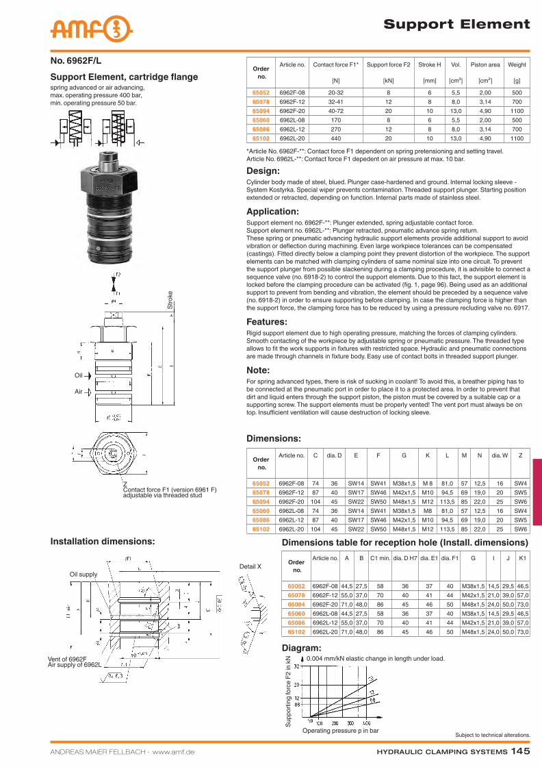
Diagram:
Dimensions table for reception hole (Install. dimensions)Installation dimensions:
0.004 mm/kN elastic change in length under load.
spring advanced or air advancing, max. operating pressure 400 bar, min. operating pressure 50 bar.
Support Element, cartridge flangeNo. 6962F/L
Order no.
Article no. A B C1 min. dia. D H7 dia. E1 dia. F1 G I J K1
65052 6962F-08 44,5 27,5 58 36 37 40 M38x1,5 14,5 29,5 46,565078 6962F-12 55,0 37,0 70 40 41 44 M42x1,5 21,0 39,0 57,065094 6962F-20 71,0 48,0 86 45 46 50 M48x1,5 24,0 50,0 73,065060 6962L-08 44,5 27,5 58 36 37 40 M38x1,5 14,5 29,5 46,565086 6962L-12 55,0 37,0 70 40 41 44 M42x1,5 21,0 39,0 57,065102 6962L-20 71,0 48,0 86 45 46 50 M48x1,5 24,0 50,0 73,0
Order no.
Article no. C dia. D E F G K L M N dia. W Z
65052 6962F-08 74 36 SW14 SW41 M38x1,5 M 8 81,0 57 12,5 16 SW465078 6962F-12 87 40 SW17 SW46 M42x1,5 M10 94,5 69 19,0 20 SW565094 6962F-20 104 45 SW22 SW50 M48x1,5 M12 113,5 85 22,0 25 SW665060 6962L-08 74 36 SW14 SW41 M38x1,5 M8 81,0 57 12,5 16 SW465086 6962L-12 87 40 SW17 SW46 M42x1,5 M10 94,5 69 19,0 20 SW565102 6962L-20 104 45 SW22 SW50 M48x1,5 M12 113,5 85 22,0 25 SW6
Dimensions:
Design:Cylinder body made of steel, blued. Plunger case-hardened and ground. Internal locking sleeve - System Kostyrka. Special wiper prevents contamination. Threaded support plunger. Starting position extended or retracted, depending on function. Internal parts made of stainless steel.
Application:Support element no. 6962F-**: Plunger extended, spring adjustable contact force. Support element no. 6962L-**: Plunger retracted, pneumatic advance spring return. These spring or pneumatic advancing hydraulic support elements provide additional support to avoid vibration or deflection during machining. Even large workpiece tolerances can be compensated (castings). Fitted directly below a clamping point they prevent distortion of the workpiece. The support elements can be matched with clamping cylinders of same nominal size into one circuit. To prevent the support plunger from possible slackening during a clamping procedure, it is advisible to connect a sequence valve (no. 6918-2) to control the support elements. Due to this fact, the support element is locked before the clamping procedure can be activated (fig. 1, page 96). Being used as an additional support to prevent from bending and vibration, the element should be preceded by a sequence valve (no. 6918-2) in order to ensure supporting before clamping. In case the clamping force is higher than the support force, the clamping force has to be reduced by using a pressure recluding valve no. 6917.
Features:Rigid support element due to high operating pressure, matching the forces of clamping cylinders. Smooth contacting of the workpiece by adjustable spring or pneumatic pressure. The threaded type allows to fit the work supports in fixtures with restricted space. Hydraulic and pneumatic connections are made through channels in fixture body. Easy use of contact bolts in threaded support plunger.
Note:For spring advanced types, there is risk of sucking in coolant! To avoid this, a breather piping has to be connected at the pneumatic port in order to place it to a protected area. In order to prevent that dirt and liquid enters through the support piston, the piston must be covered by a suitable cap or a supporting screw. The support elements must be properly vented! The vent port must always be on top. Insufficient ventilation will cause destruction of locking sleeve.
Order no.
Article no. Contact force F1*
[N]
Support force F2
[kN]
Stroke H
[mm]
Vol.
[cm³]
Piston area
[cm²]
Weight
[g]
65052 6962F-08 20-32 8 6 5,5 2,00 50065078 6962F-12 32-41 12 8 8,0 3,14 70065094 6962F-20 40-72 20 10 13,0 4,90 110065060 6962L-08 170 8 6 5,5 2,00 50065086 6962L-12 270 12 8 8,0 3,14 70065102 6962L-20 440 20 10 13,0 4,90 1100
*Article No. 6962F-**: Contact force F1 dependent on spring pretensioning and setting travel. Article No. 6962L-**: Contact force F1 depedent on air pressure at max. 10 bar.
Stro
ke
Operating pressure p in bar
Supp
ortin
g fo
rce
F2 in
kN
Z Contact force F1 (version 6961 F) adjustable via threaded stud
Vent of 6962FAir supply of 6962L
Oil supplyDetail X
Air
Oil
Katalog_2012_Hydraulik_EN_ohnePreise.indd 145 3/28/2013 8:35:14 AM
146 Hydraulic clamping SyStemS ANDREAS MAIER FELLBACH ∙ www.amf.de
Subject to technical alterations.
Support Element
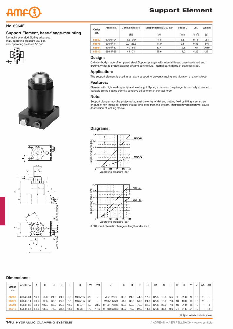
Normally extended. Spring advanced, max. operating pressure 350 bar, min. operating pressure 50 bar.
Support Element, base-flange-mountingNo. 6964F
Order no.
Article no. Contact force F1
[N]
Support force at 350 bar
[kN]
Stroke C
[mm]
Vol.
[cm³]
Weight
[g]
66852 6964F-04 4,5 - 9,0 4,4 6,5 0,16 28166878 6964F-11 9,0 - 26,5 11,0 9,5 0,33 84066894 6964F-33 40 - 80 33,4 12,5 1,64 201966910 6964F-55 49 - 71 55,6 19,0 4,26 4291
Design:Cylinder body made of tempered steel. Support plunger with internal thread case-hardened and ground. Wiper to protect against dirt and cutting fluid. Internal parts made of stainless steel.
Application:The support element is used as an extra support to prevent sagging and vibration of a workpiece.
Features:Element with high load capacity and low height. Spring extension: the plunger is normally extended. Variable spring setting permits sensitive adjustment of contact force.
Note:Support plunger must be protected against the entry of dirt and cutting fluid by fitting a set screw or plug. When installing, ensure that all air is bled from the system. Insufficient ventilation will cause destruction of locking sleeve.
Dimensions:
Order no.
Article no. A B D E F G SW SW1 J K M P Q R1 S T W X Y Z AA AC
66852 6964F-04 16,0 56,0 24,5 24,0 5,5 M26x1,5 23 - M8x1,25x5 33,5 24,5 44,5 17,5 G1/8 13,0 5,5 9 31,0 9 10 7° -66878 6964F-11 20,5 70,5 33,0 25,0 6,5 M35x1,5 30 - M10x1,50x9 41,0 30,0 59,0 24,0 G1/8 18,0 7,0 10 43,0 10 10 7° -66894 6964F-33 38,0 107,0 68,5 25,0 12,5 Ø 57 50 28,5 M12x1,75x15 63,5 52,5 76,0 31,5 G1/8 26,0 7,0 16 61,0 16 10 - 466910 6964F-55 51,0 133,0 76,0 31,5 12,5 Ø 76 70 41,5 M16x2,00x22 89,0 73,0 97,0 44,5 G1/8 36,5 9,0 24 81,5 24 10 - 4
Diagrams:
0.004 mm/kN elastic change in length under load.
Oil c
onne
ctio
n
Operating pressure [bar]
Supp
ortin
g fo
rce
[kN
]
Vent
scr
ew
Operating pressure [bar]
Supp
ortin
g fo
rce
[kN
]
Katalog_2012_Hydraulik_EN_ohnePreise.indd 146 3/28/2013 8:35:17 AM
ANDREAS MAIER FELLBACH ∙ www.amf.de Hydraulic clamping SyStemS 147
Subject to technical alterations.
Support Element
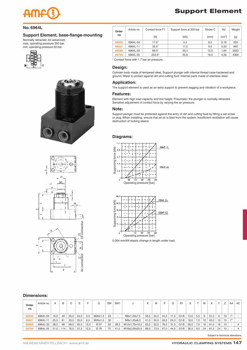
Normally retracted. Air advanced, max. operating pressure 350 bar, min. operating pressure 50 bar.
Support Element, base-flange-mountingNo. 6964L
Order no.
Article no. Contact force F1
[N]
Support force at 350 bar
[kN]
Stroke C
[mm]
Vol.
[cm³]
Weight
[g]
66936 6964L-04 17,5* 4,4 6,5 0,16 25566621 6964L-11 35,5* 11,0 9,5 0,33 84066688 6964L-33 89,0* 33,4 12,5 1,64 202366704 6964L-55 253,3* 55,6 19,0 4,26 4300
* Contact force with 1.7 bar air pressure.
Design:Cylinder body made of tempered steel. Support plunger with internal thread case-hardened and ground. Wiper to protect against dirt and cutting fluid. Internal parts made of stainless steel.
Application:The support element is used as an extra support to prevent sagging and vibration of a workpiece.
Features:Element with high load capacity and low height. Pneumatic: the plunger is normally retracted. Sensitive adjustment of contact force by varying the air pressure.
Note:Support plunger must be protected against the entry of dirt and cutting fluid by fitting a set screw or plug. When installing, ensure that all air is bled from the system. Insufficient ventilation will cause destruction of locking sleeve.
Dimensions:
Order no.
Article no. A B D E F G SW SW1 J K M P Q R1 S T W X Y Z AA AC
66936 6964L-04 16,0 49 25,0 24,0 5,5 M26x1,5 23 - M6x1,00x7,5 33,5 24,5 44,5 17,5 G1/8 13,0 5,5 9 31,0 9 10 7° -66621 6964L-11 20,5 61 33,0 25,0 6,5 M35x1,5 30 - M8x1,25x6,0 41,0 30,0 59,0 24,0 G1/8 18,0 7,0 10 43,0 10 10 7° -66688 6964L-33 38,0 98 68,5 25,0 12,5 Ø 57 50 28,5 M12x1,75x15,0 63,5 52,5 76,0 31,5 G1/8 26,0 7,0 16 61,0 16 10 - 466704 6964L-55 51,0 114 76,0 31,5 12,5 Ø 76 70 41,5 M16x2,00x20,0 89,0 73,0 97,0 44,5 G1/8 36,5 9,0 24 81,5 24 10 - 4
Diagrams:
0.004 mm/kN elastic change in length under load.
Oil c
onne
ctio
n
Operating pressure [bar]
Supp
ortin
g fo
rce
[kN
]
Operating pressure [bar]
Supp
ortin
g fo
rce
[kN
]
Air c
onne
ctio
n
Katalog_2012_Hydraulik_EN_ohnePreise.indd 147 3/28/2013 8:35:20 AM
148 Hydraulic clamping SyStemS ANDREAS MAIER FELLBACH ∙ www.amf.de
Subject to technical alterations.
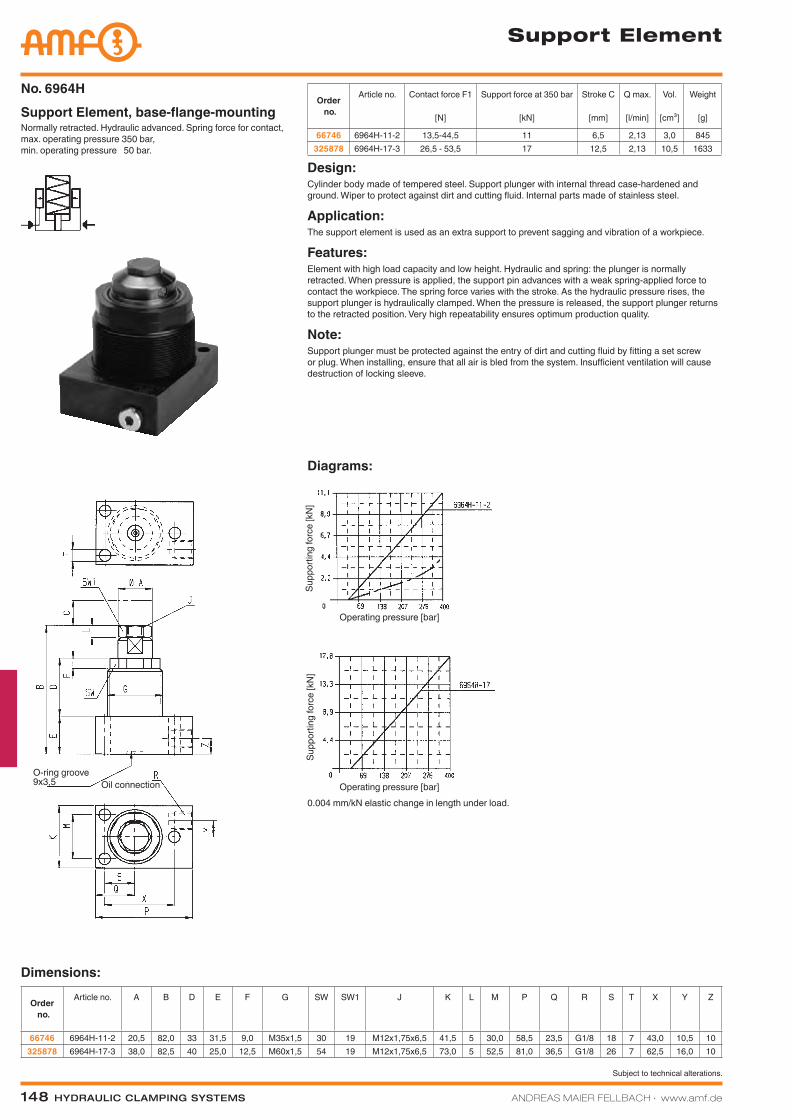
Normally retracted. Hydraulic advanced. Spring force for contact, max. operating pressure 350 bar, min. operating pressure 50 bar.
Support Element, base-flange-mountingNo. 6964H
Order no.
Article no. Contact force F1
[N]
Support force at 350 bar
[kN]
Stroke C
[mm]
Q max.
[l/min]
Vol.
[cm³]
Weight
[g]
66746 6964H-11-2 13,5-44,5 11 6,5 2,13 3,0 845325878 6964H-17-3 26,5 - 53,5 17 12,5 2,13 10,5 1633
Design:Cylinder body made of tempered steel. Support plunger with internal thread case-hardened and ground. Wiper to protect against dirt and cutting fluid. Internal parts made of stainless steel.
Application:The support element is used as an extra support to prevent sagging and vibration of a workpiece.
Features:Element with high load capacity and low height. Hydraulic and spring: the plunger is normally retracted. When pressure is applied, the support pin advances with a weak spring-applied force to contact the workpiece. The spring force varies with the stroke. As the hydraulic pressure rises, the support plunger is hydraulically clamped. When the pressure is released, the support plunger returns to the retracted position. Very high repeatability ensures optimum production quality.
Note:Support plunger must be protected against the entry of dirt and cutting fluid by fitting a set screw or plug. When installing, ensure that all air is bled from the system. Insufficient ventilation will cause destruction of locking sleeve.
Dimensions:
Order no.
Article no. A B D E F G SW SW1 J K L M P Q R S T X Y Z
66746 6964H-11-2 20,5 82,0 33 31,5 9,0 M35x1,5 30 19 M12x1,75x6,5 41,5 5 30,0 58,5 23,5 G1/8 18 7 43,0 10,5 10325878 6964H-17-3 38,0 82,5 40 25,0 12,5 M60x1,5 54 19 M12x1,75x6,5 73,0 5 52,5 81,0 36,5 G1/8 26 7 62,5 16,0 10
Diagrams:
0.004 mm/kN elastic change in length under load.
Support Element
Operating pressure [bar]
Supp
ortin
g fo
rce
[kN
]
Operating pressure [bar]
Supp
ortin
g fo
rce
[kN
]
Oil connectionO-ring groove 9x3,5
Katalog_2012_Hydraulik_EN_ohnePreise.indd 148 3/28/2013 8:35:22 AM
ANDREAS MAIER FELLBACH ∙ www.amf.de Hydraulic clamping SyStemS 149
Subject to technical alterations.
Order no.
Article no. Contact force F1
[N]
Support force at 350 bar
[kN]
Stroke C
[mm]
Vol.
[cm³]
Md
[Nm]
Weight
[g]
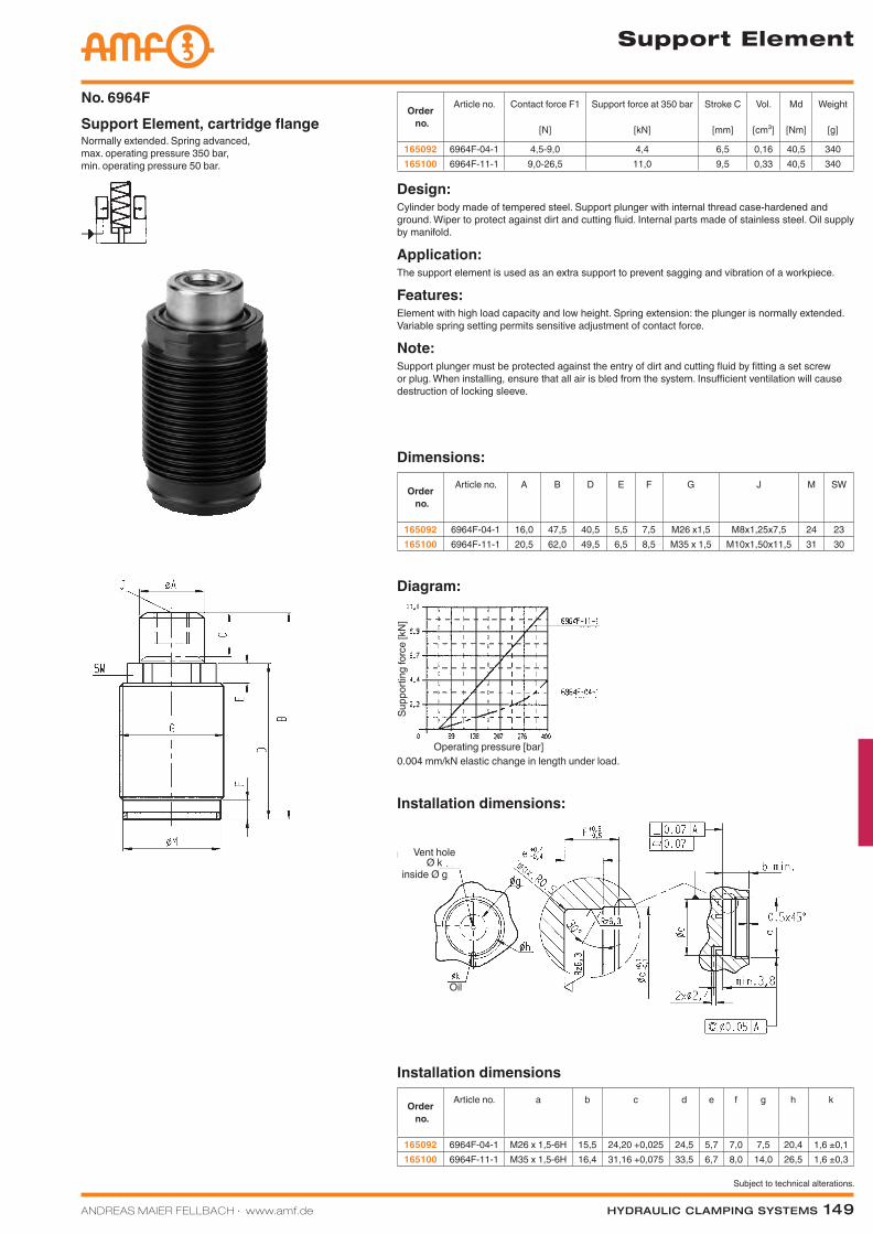
165092 6964F-04-1 4,5-9,0 4,4 6,5 0,16 40,5 340165100 6964F-11-1 9,0-26,5 11,0 9,5 0,33 40,5 340
Normally extended. Spring advanced, max. operating pressure 350 bar, min. operating pressure 50 bar.
Support Element, cartridge flangeNo. 6964F
Order no.
Article no. A B D E F G J M SW
165092 6964F-04-1 16,0 47,5 40,5 5,5 7,5 M26 x1,5 M8x1,25x7,5 24 23165100 6964F-11-1 20,5 62,0 49,5 6,5 8,5 M35 x 1,5 M10x1,50x11,5 31 30
Dimensions:
Design:Cylinder body made of tempered steel. Support plunger with internal thread case-hardened and ground. Wiper to protect against dirt and cutting fluid. Internal parts made of stainless steel. Oil supply by manifold.
Application:The support element is used as an extra support to prevent sagging and vibration of a workpiece.
Features:Element with high load capacity and low height. Spring extension: the plunger is normally extended. Variable spring setting permits sensitive adjustment of contact force.
Note:Support plunger must be protected against the entry of dirt and cutting fluid by fitting a set screw or plug. When installing, ensure that all air is bled from the system. Insufficient ventilation will cause destruction of locking sleeve.
Order no.
Article no. a b c d e f g h k
165092 6964F-04-1 M26 x 1,5-6H 15,5 24,20 +0,025 24,5 5,7 7,0 7,5 20,4 1,6 ±0,1165100 6964F-11-1 M35 x 1,5-6H 16,4 31,16 +0,075 33,5 6,7 8,0 14,0 26,5 1,6 ±0,3
Installation dimensions
Installation dimensions:
Diagram:
0.004 mm/kN elastic change in length under load.
Support Element
Operating pressure [bar]
Supp
ortin
g fo
rce
[kN
]
Vent hole Ø k
Oil
inside Ø g
Katalog_2012_Hydraulik_EN_ohnePreise.indd 149 3/28/2013 8:35:25 AM
150 Hydraulic clamping SyStemS ANDREAS MAIER FELLBACH ∙ www.amf.de
Subject to technical alterations.
Installation dimensions:
Diagram:
Installation dimensions:
0.004 mm/kN elastic change in length under load.
Support Element
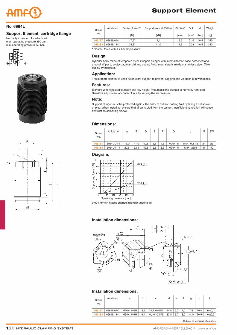
Normally extended. Air advanced, max. operating pressure 350 bar, min. operating pressure 50 bar.
Support Element, cartridge flangeNo. 6964L
Order no.
Article no. Contact force F1
[N]
Support force at 350 bar
[kN]
Stroke C
[mm]
Vol.
[cm³]
Md
[Nm]
Weight
[g]
165167 6964L-04-1 17,5* 4,4 6,5 0,16 40,5 340165183 6964L-11-1 35,5* 11,0 9,5 0,33 40,5 340
* Contact force with 1.7 bar air pressure.
Design:Cylinder body made of tempered steel. Support plunger with internal thread case-hardened and ground. Wiper to protect against dirt and cutting fluid. Internal parts made of stainless steel. Oil/Air supply by manifold.
Application:The support element is used as an extra support to prevent sagging and vibration of a workpiece.
Features:Element with high load capacity and low height. Pneumatic: the plunger is normally retracted. Sensitive adjustment of contact force by varying the air pressure.
Note:Support plunger must be protected against the entry of dirt and cutting fluid by fitting a set screw or plug. When installing, ensure that all air is bled from the system. Insufficient ventilation will cause destruction of locking sleeve.
Order no.
Article no. A B D E F G J M SW
165167 6964L-04-1 16,0 41,0 40,5 5,5 7,5 M26x1,5 M6x1,00x7,5 24 23165183 6964L-11-1 20,5 52,5 49,5 6,5 8,5 M35x1,5 M8x1,25x6 31 30
Dimensions:
Order no.
Article no. a b c d e f g h k
165167 6964L-04-1 M26x1,5-6H 15,5 24,2 +0,025 24,5 5,7 7,0 7,5 20,4 1,6 ±0,1165183 6964L-11-1 M35x1,5-6H 16,4 31,16 +0,075 33,5 6,7 8,0 14,0 26,5 1,6 ±0,3
Air
Oil
Operating pressure [bar]
Supp
ortin
g fo
rce
[kN
]
inside Ø g
Katalog_2012_Hydraulik_EN_ohnePreise.indd 150 3/28/2013 8:35:27 AM
ANDREAS MAIER FELLBACH ∙ www.amf.de Hydraulic clamping SyStemS 151
Subject to technical alterations.
Installation dimensions:
Installation dimensions No. 6964H-17-1
Diagram:
Installation dimensions No. 6964H-04-1 and -11-1
0.004 mm/kN elastic change in length under load.
Support Element
Order no.
Article no. Contact force F1
[N]
Support force at 350 bar
[kN]
Stroke C
[mm]
max. oil flow rate[l/min.]
Vol.
[cm³]
Md
[Nm]
Weight
[g]
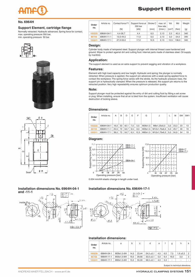
165225 6964H-04-1 4,4-26,7 4,4 6,5 2,13 2,5 40,5 34066720 6964H-11-1 13,5-44,5 11,0 6,5 2,13 3,0 54,0 340
165241 6964H-17-1 27,0-53,0 17,0 12,5 2,13 10,5 136,0 340
Normally retracted. Hydraulic advanced. Spring force for contact, max. operating pressure 350 bar, min. operating pressure 50 bar.
Support Element, cartridge flangeNo. 6964H
Design:Cylinder body made of tempered steel. Support plunger with internal thread case-hardened and ground. Wiper to protect against dirt and cutting fluid. Internal parts made of stainless steel. Oil supply by manifold.
Application:The support element is used as an extra support to prevent sagging and vibration of a workpiece.
Features:Element with high load capacity and low height. Hydraulic and spring: the plunger is normally retracted. When pressure is applied, the support pin advances with a weak spring-applied force to contact the workpiece. The spring force varies with the stroke. As the hydraulic pressure rises, the support pin is hydraulically clamped. When the pressure is released, the support pin returns to the retracted position. Very high repeatability ensures optimum production quality.
Note:Support plunger must be protected against the entry of dirt and cutting fluid by fitting a set screw or plug. When installing, ensure that all air is bled from the system. Insufficient ventilation will cause destruction of locking sleeve.
Order no.
Article no. A B D E F G J L M SW SW1
165225 6964H-04-1 16,0 53 42,1 7,0 5,5 M26x1,5 M8x1,25x5,0 3,5 23,3 23 1366720 6964H-11-1 20,5 72 54,7 9,5 9,0 M35x1,5 M12x1,75x6,5 5,0 29,7 30 19
165241 6964H-17-1 38,0 72 54,7 6,5 12,5 M60x1,5 M12x1,75x6,5 5,0 54,9 54 19
Dimensions:
Order no.
Article no. a b c d e f g h k
165225 6964H-04-1 M26x1,5-6H 14,5 23,44 24,5 ±0,1 4,5 6,0 7,5 1,6 ±0,3 266720 6964H-11-1 M35x1,5-6H 19,0 29,90 33,5 ±0,1 5,0 6,4 19,0 3,0 3
165241 6964H-17-1 M60x1,5-6H 15,0 55,00 58,5 ±0,1 4,0 5,3 - - -
Operating pressure [bar] Operating pressure [bar]
Supp
ortin
g fo
rce
[kN
]
Supp
ortin
g fo
rce
[kN
]
inside Ø g
Seal
Katalog_2012_Hydraulik_EN_ohnePreise.indd 151 3/28/2013 8:35:32 AM
152 Hydraulic clamping SyStemS ANDREAS MAIER FELLBACH ∙ www.amf.de
Subject to technical alterations.
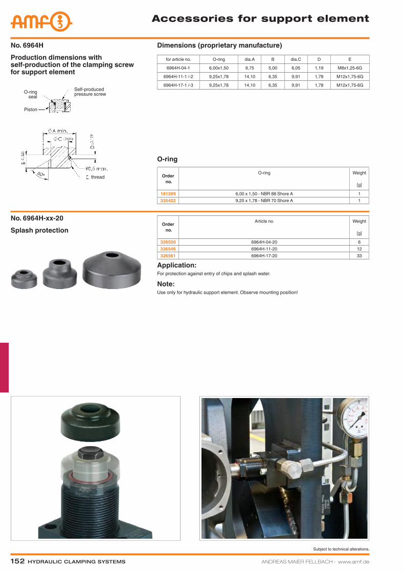
Accessories for support element
No. 6964HProduction dimensions with self-production of the clamping screw for support element
Dimensions (proprietary manufacture)
Splash protectionNo. 6964H-xx-20
Order no.
Article no. Weight
[g]
326520 6964H-04-20 6326546 6964H-11-20 12326561 6964H-17-20 33
Application:For protection against entry of chips and splash water.
Note:Use only for hydraulic support element. Observe mounting position!
for article no. O-ring dia.A B dia.C D E
6964H-04-1 6,00x1,50 9,75 5,00 6,05 1,19 M8x1,25-6G
6964H-11-1 /-2 9,25x1,78 14,10 6,35 9,91 1,78 M12x1,75-6G
6964H-17-1 /-3 9,25x1,78 14,10 6,35 9,91 1,78 M12x1,75-6G
O-ring
Order no.
O-ring Weight
[g]
181289 6,00 x 1,50 - NBR 88 Shore A 1335422 9,25 x 1,78 - NBR 70 Shore A 1
Self-produced pressure screw
thread
Piston
O-ring seal
Katalog_2012_Hydraulik_EN_ohnePreise.indd 152 3/28/2013 8:35:45 AM
Subject to technical alterations.
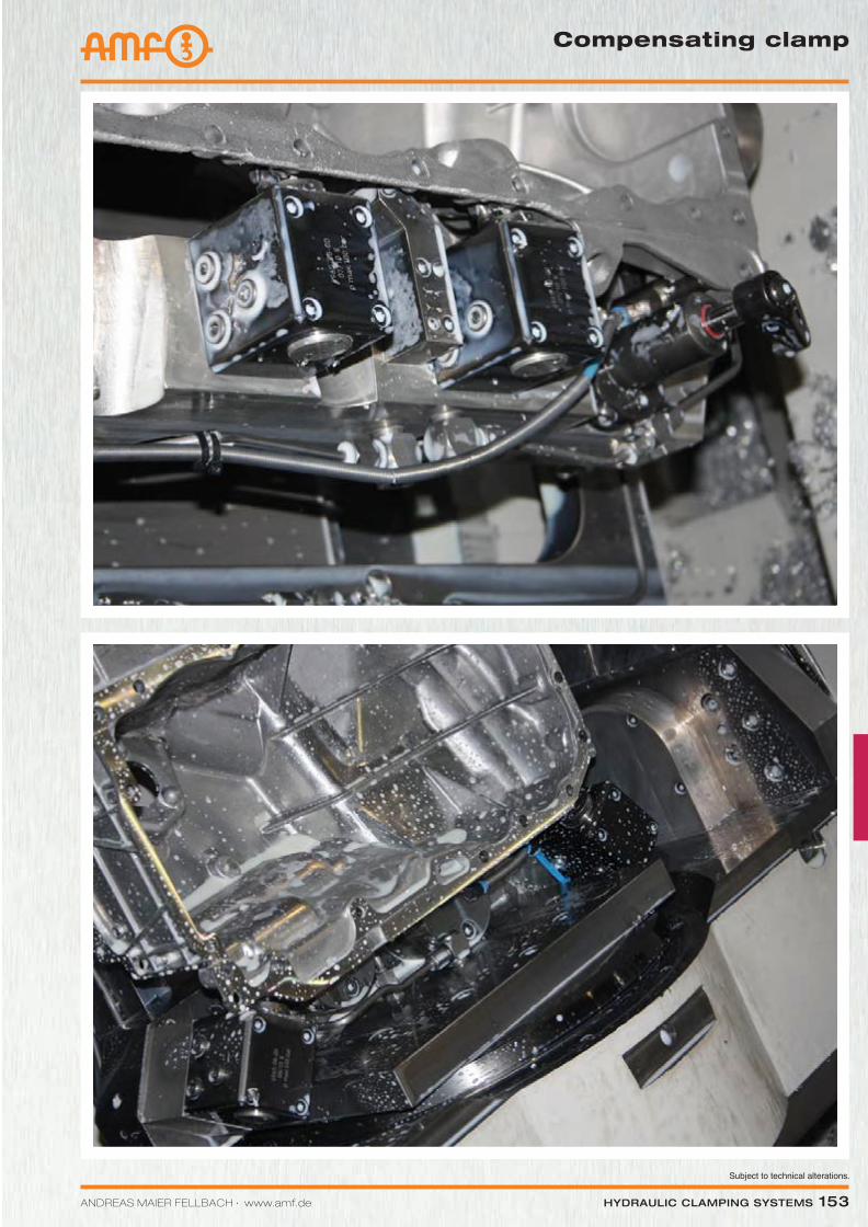
ANDREAS MAIER FELLBACH ∙ www.amf.de Hydraulic clamping SyStemS 153
Compensating clamp
Katalog_2012_Hydraulik_EN_ohnePreise.indd 153 3/28/2013 8:35:49 AM
154 Hydraulic clamping SyStemS ANDREAS MAIER FELLBACH ∙ www.amf.de
Subject to technical alterations.
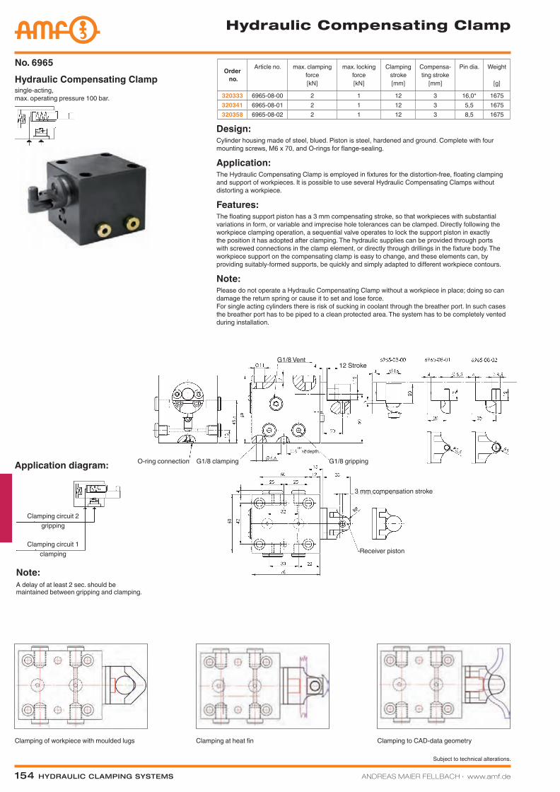
Note:A delay of at least 2 sec. should be maintained between gripping and clamping.
Application diagram:
Order no.
Article no. max. clamping force[kN]
max. locking force[kN]
Clamping stroke[mm]
Compensa-ting stroke
[mm]
Pin dia. Weight
[g]
320333 6965-08-00 2 1 12 3 16,0* 1675320341 6965-08-01 2 1 12 3 5,5 1675320358 6965-08-02 2 1 12 3 8,5 1675
single-acting, max. operating pressure 100 bar.
Hydraulic Compensating Clamp No. 6965
Design:Cylinder housing made of steel, blued. Piston is steel, hardened and ground. Complete with four mounting screws, M6 x 70, and O-rings for flange-sealing.
Application:The Hydraulic Compensating Clamp is employed in fixtures for the distortion-free, floating clamping and support of workpieces. It is possible to use several Hydraulic Compensating Clamps without distorting a workpiece.
Features:The floating support piston has a 3 mm compensating stroke, so that workpieces with substantial variations in form, or variable and imprecise hole tolerances can be clamped. Directly following the workpiece clamping operation, a sequential valve operates to lock the support piston in exactly the position it has adopted after clamping. The hydraulic supplies can be provided through ports with screwed connections in the clamp element, or directly through drillings in the fixture body. The workpiece support on the compensating clamp is easy to change, and these elements can, by providing suitably-formed supports, be quickly and simply adapted to different workpiece contours.
Note:Please do not operate a Hydraulic Compensating Clamp without a workpiece in place; doing so can damage the return spring or cause it to set and lose force. For single acting cylinders there is risk of sucking in coolant through the breather port. In such cases the breather port has to be piped to a clean protected area. The system has to be completely vented during installation.
Hydraulic Compensating Clamp
Clamping circuit 2
Clamping circuit 1clamping
gripping
O-ring connection G1/8 clamping G1/8 gripping
G1/8 Vent
Receiver piston
3 mm compensation stroke
12 Stroke
depth.
Clamping of workpiece with moulded lugs Clamping at heat fin Clamping to CAD-data geometry
Katalog_2012_Hydraulik_EN_ohnePreise.indd 154 3/28/2013 8:36:02 AM
Subject to technical alterations.
ANDREAS MAIER FELLBACH ∙ www.amf.de Hydraulic clamping SyStemS 155
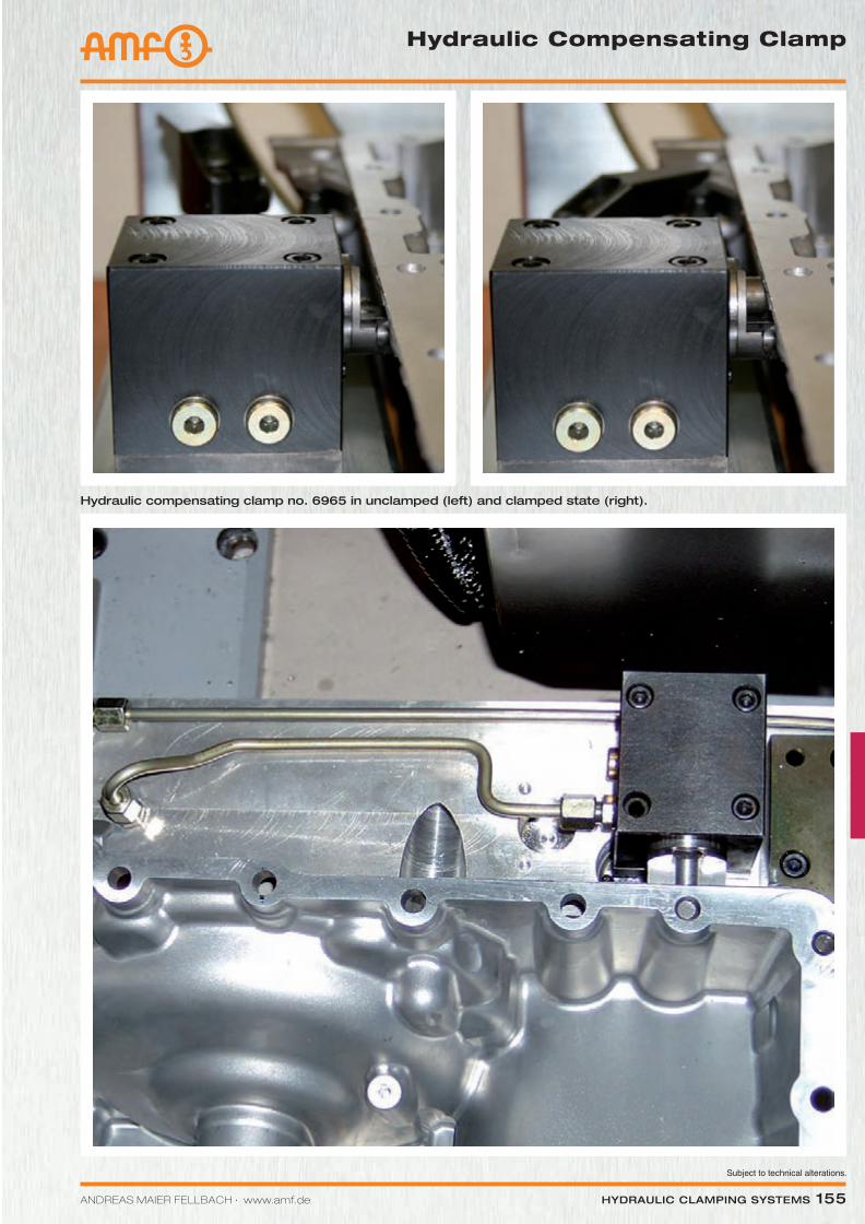
Hydraulic compensating clamp no. 6965 in unclamped (left) and clamped state (right).
Hydraulic Compensating Clamp
Katalog_2012_Hydraulik_EN_ohnePreise.indd 155 3/28/2013 8:36:10 AM
Subject to technical alterations.
156 Hydraulic clamping SyStemS ANDREAS MAIER FELLBACH ∙ www.amf.de
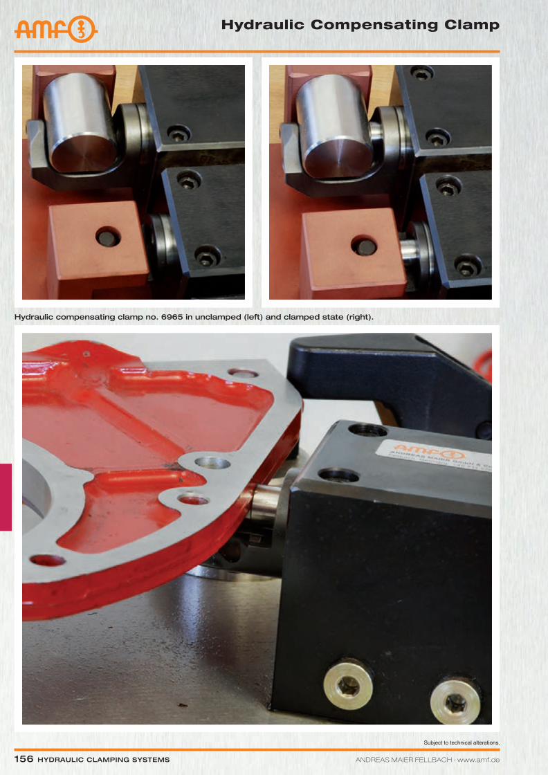
Hydraulic compensating clamp no. 6965 in unclamped (left) and clamped state (right).
Hydraulic Compensating Clamp
Katalog_2012_Hydraulik_EN_ohnePreise.indd 156 3/28/2013 8:36:18 AM
Subject to technical alterations.
ANDREAS MAIER FELLBACH ∙ www.amf.de Hydraulic clamping SyStemS 157
PRODUCT ExAMPLES:
no. 6941k no. 6942kk no. 6944gH
> Clamping force: 3,2 - 7,5 kN
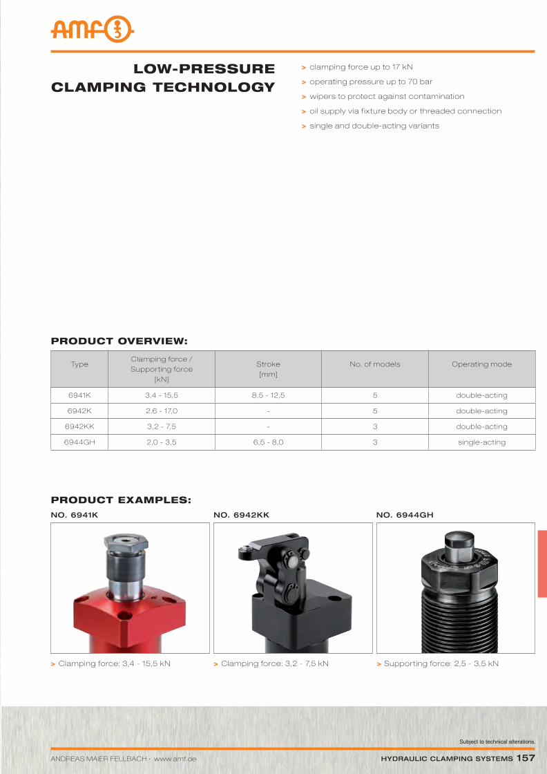
PRODUCT OVERVIEW:
TypeClamping force / Supporting force
[kN]
Stroke [mm]
No. of models Operating mode
6941K 3,4 - 15,5 8,5 - 12,5 5 double-acting
6942K 2,6 - 17,0 - 5 double-acting
6942KK 3,2 - 7,5 - 3 double-acting
6944GH 2,0 - 3,5 6,5 - 8,0 3 single-acting
> clamping force up to 17 kN
> operating pressure up to 70 bar
> wipers to protect against contamination
> oil supply via fixture body or threaded connection
> single and double-acting variants
LOW-PRESSURE CLAMPING TECHNOLOGY
> Clamping force: 3,4 - 15,5 kN > Supporting force: 2,5 - 3,5 kN
Katalog_2012_Hydraulik_EN_ohnePreise.indd 157 3/28/2013 8:36:24 AM
158 Hydraulic clamping SyStemS ANDREAS MAIER FELLBACH ∙ www.amf.de
Subject to technical alterations.
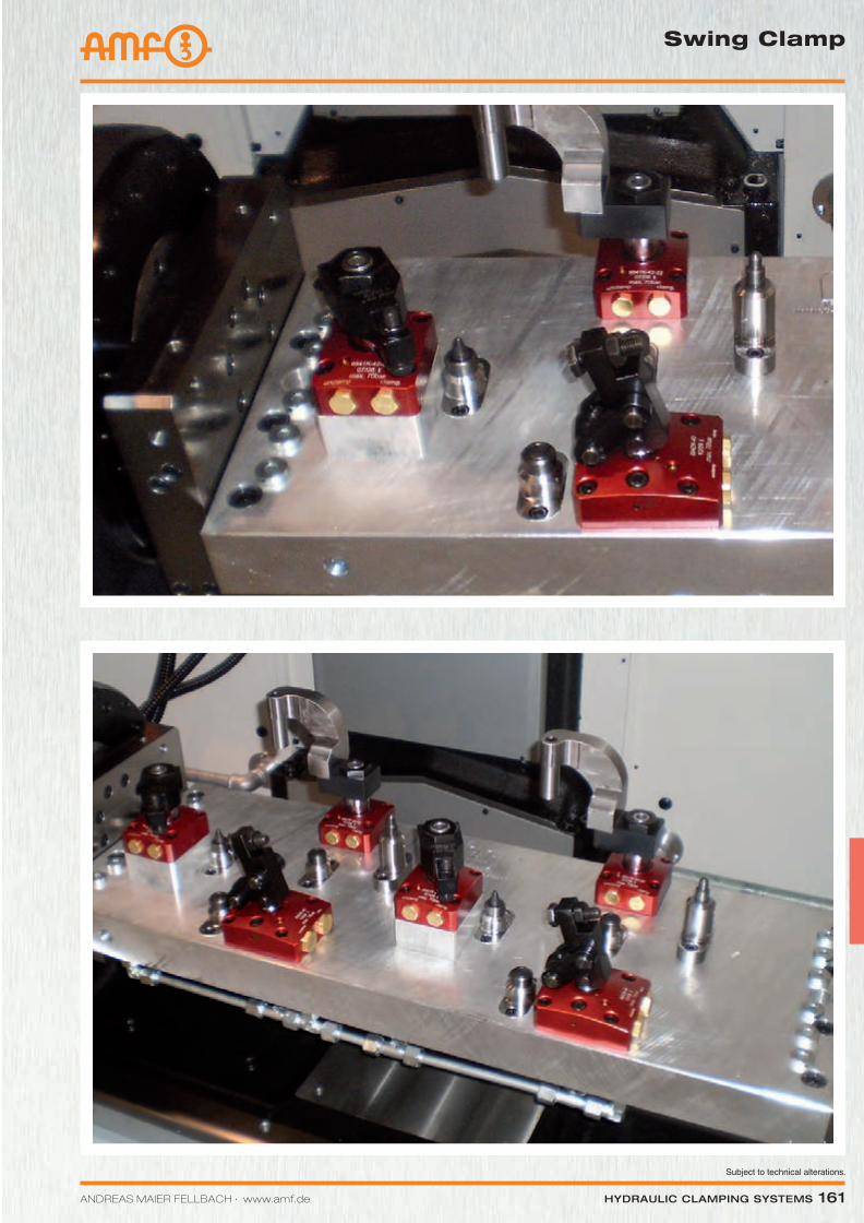
Swing Clamp
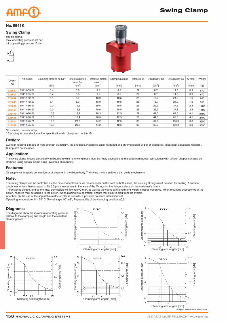
double acting, max. operating pressure 70 bar, min. operating pressure 15 bar.
Swing ClampNo. 6941K
Sp = clamp, Lo = unclamp * Clamping force and volume flow specification with clamp arm no. 6941S.
Design:Cylinder housing is made of high-strength aluminium, red anodised. Piston rod case-hardened and chrome plated. Wiper at piston rod. Integrated, adjustable restrictor. Clamp arm not included.
Application:The swing clamp is used particularly in fixtures in which the workpieces must be freely accessible and loaded from above. Workpieces with difficult shapes can also be clamped using special clamp arms (available on request).
Features:Oil supply via threaded connection or oil channel in the fixture body. The swing motion emloys a ball guide mechanism.
Note:The swing clamps can be controlled via the pipe connections or via the channels on the front. In both cases, the existing O-rings must be used for sealing. A surface roughness of less than or equal to Rz 6.3 µm is necessary in the area of the O-rings for the flange surface on the customer‘s fixture. The piston is guided, and so the max. permissible oil flow rate Q max. as well as the clamp arm length and weight must be observed. When mounting accessories at the piston, no force may be applied to the piston. When placing into operation, ensure that all air is bled from the system. Attention: By the use of the adjustable restrictor please consider a possible pressure intensification! Operating temperature: 0° - 70° C, Swivel angle: 90° ±3°, Repeatability of the clamping position: ±0,5°.
Order no.
Article no. Clamping force at 70 bar*
[kN]
effective piston area Sp
[cm²]
effective piston area Lo
[cm²]
Clamping stroke
[mm]
Total stroke
[mm]
Oil capacity Sp
[cm³]
Oil capacity Lo
[cm³]
Q max.
[l/min]
Weight
[g]
326587 6941K-35-21 3,4 5,8 9,6 8,5 22 8,7 14,5 0,9 670326603 6941K-35-22 3,4 5,8 9,6 8,5 22 8,7 14,5 0,9 670326629 6941K-42-21 5,1 8,9 13,9 10,5 25 15,7 24,2 1,6 950326645 6941K-42-22 5,1 8,9 13,9 10,5 25 15,7 24,2 1,6 950326660 6941K-50-21 7,0 12,6 19,6 10,5 26 23,9 37,3 2,4 1400326454 6941K-50-22 7,0 12,6 19,6 10,5 26 23,9 37,3 2,4 1400326470 6941K-60-21 10,3 18,4 28,3 12,5 29 41,3 63,6 4,1 2100326496 6941K-60-22 10,3 18,4 28,3 12,5 29 41,3 63,6 4,1 2100326512 6941K-75-21 15,5 28,3 44,2 12,5 30 67,9 106,0 6,8 3350326538 6941K-75-22 15,5 28,3 44,2 12,5 30 67,9 106,0 6,8 3350
Diagrams:The diagrams show the maximum operating pressure relative to the clamping arm length and the resultant clamping force.
Clamping arm lengths [mm]
Clamping arm lengths [mm]
Clamping arm lengths [mm]
Ope
ratin
g pr
essu
re [b
ar]
Ope
ratin
g pr
essu
re [b
ar]
Ope
ratin
g pr
essu
re [b
ar]
Cla
mpi
ng fo
rce
[kN
]
Cla
mpi
ng fo
rce
[kN
]C
lam
ping
forc
e [k
N]
Cla
mpi
ng fo
rce
[kN
]C
lam
ping
forc
e [k
N]
Ope
ratin
g pr
essu
re [b
ar]
Ope
ratin
g pr
essu
re [b
ar]
Clamping arm lengths [mm]Clamping arm lengths [mm]
Katalog_2012_Hydraulik_EN_ohnePreise.indd 158 3/28/2013 8:36:28 AM
ANDREAS MAIER FELLBACH ∙ www.amf.de Hydraulic clamping SyStemS 159
Subject to technical alterations.
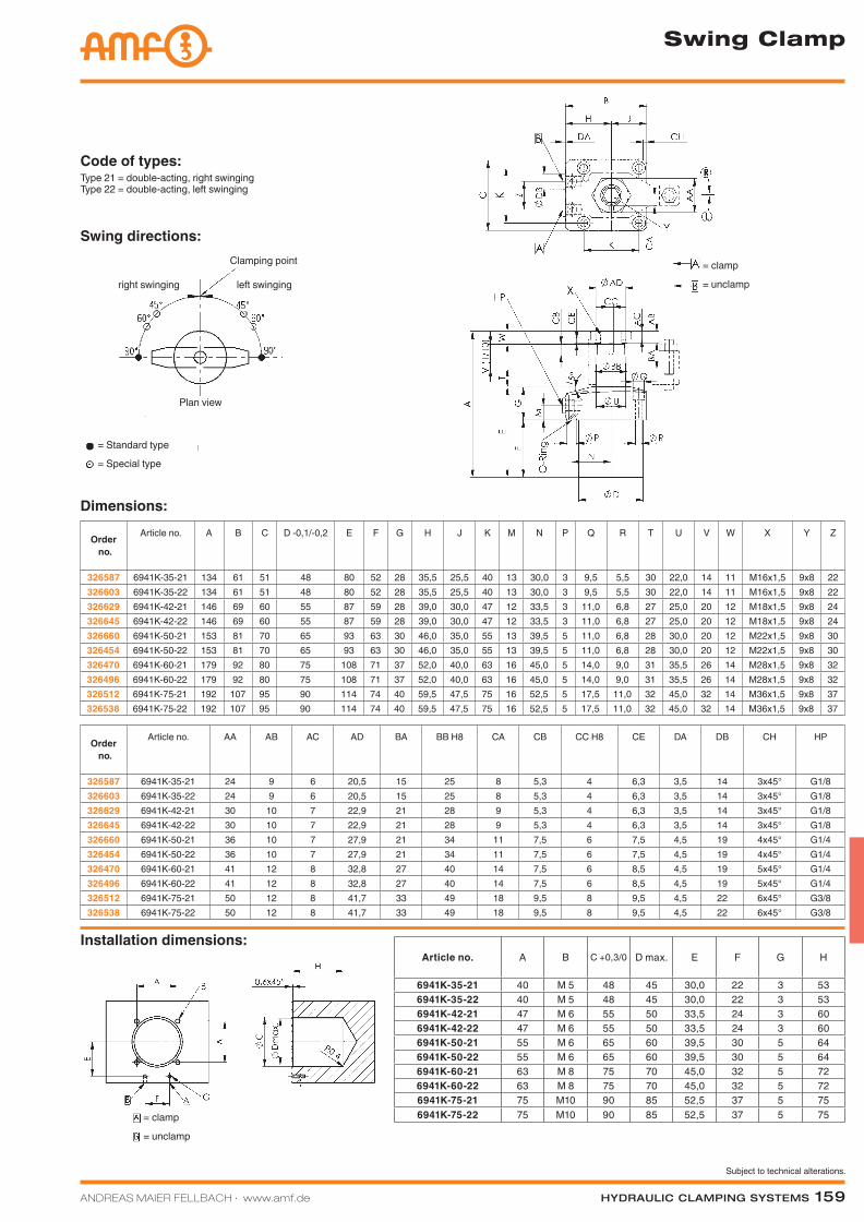
Article no. A B C +0,3/0 D max. E F G H
6941K-35-21 40 M 5 48 45 30,0 22 3 536941K-35-22 40 M 5 48 45 30,0 22 3 536941K-42-21 47 M 6 55 50 33,5 24 3 606941K-42-22 47 M 6 55 50 33,5 24 3 606941K-50-21 55 M 6 65 60 39,5 30 5 646941K-50-22 55 M 6 65 60 39,5 30 5 646941K-60-21 63 M 8 75 70 45,0 32 5 726941K-60-22 63 M 8 75 70 45,0 32 5 726941K-75-21 75 M10 90 85 52,5 37 5 756941K-75-22 75 M10 90 85 52,5 37 5 75
Installation dimensions:
Code of types:Type 21 = double-acting, right swingingType 22 = double-acting, left swinging
Swing directions:Clamping point
right swinging left swinging
= Standard type
= Special type
Plan view
Swing Clamp
Dimensions:
Order no.
Article no. A B C D -0,1/-0,2 E F G H J K M N P Q R T U V W X Y Z
326587 6941K-35-21 134 61 51 48 80 52 28 35,5 25,5 40 13 30,0 3 9,5 5,5 30 22,0 14 11 M16x1,5 9x8 22326603 6941K-35-22 134 61 51 48 80 52 28 35,5 25,5 40 13 30,0 3 9,5 5,5 30 22,0 14 11 M16x1,5 9x8 22326629 6941K-42-21 146 69 60 55 87 59 28 39,0 30,0 47 12 33,5 3 11,0 6,8 27 25,0 20 12 M18x1,5 9x8 24326645 6941K-42-22 146 69 60 55 87 59 28 39,0 30,0 47 12 33,5 3 11,0 6,8 27 25,0 20 12 M18x1,5 9x8 24326660 6941K-50-21 153 81 70 65 93 63 30 46,0 35,0 55 13 39,5 5 11,0 6,8 28 30,0 20 12 M22x1,5 9x8 30326454 6941K-50-22 153 81 70 65 93 63 30 46,0 35,0 55 13 39,5 5 11,0 6,8 28 30,0 20 12 M22x1,5 9x8 30326470 6941K-60-21 179 92 80 75 108 71 37 52,0 40,0 63 16 45,0 5 14,0 9,0 31 35,5 26 14 M28x1,5 9x8 32326496 6941K-60-22 179 92 80 75 108 71 37 52,0 40,0 63 16 45,0 5 14,0 9,0 31 35,5 26 14 M28x1,5 9x8 32326512 6941K-75-21 192 107 95 90 114 74 40 59,5 47,5 75 16 52,5 5 17,5 11,0 32 45,0 32 14 M36x1,5 9x8 37326538 6941K-75-22 192 107 95 90 114 74 40 59,5 47,5 75 16 52,5 5 17,5 11,0 32 45,0 32 14 M36x1,5 9x8 37
Order no.
Article no. AA AB AC AD BA BB H8 CA CB CC H8 CE DA DB CH HP
326587 6941K-35-21 24 9 6 20,5 15 25 8 5,3 4 6,3 3,5 14 3x45° G1/8326603 6941K-35-22 24 9 6 20,5 15 25 8 5,3 4 6,3 3,5 14 3x45° G1/8326629 6941K-42-21 30 10 7 22,9 21 28 9 5,3 4 6,3 3,5 14 3x45° G1/8326645 6941K-42-22 30 10 7 22,9 21 28 9 5,3 4 6,3 3,5 14 3x45° G1/8326660 6941K-50-21 36 10 7 27,9 21 34 11 7,5 6 7,5 4,5 19 4x45° G1/4326454 6941K-50-22 36 10 7 27,9 21 34 11 7,5 6 7,5 4,5 19 4x45° G1/4326470 6941K-60-21 41 12 8 32,8 27 40 14 7,5 6 8,5 4,5 19 5x45° G1/4326496 6941K-60-22 41 12 8 32,8 27 40 14 7,5 6 8,5 4,5 19 5x45° G1/4326512 6941K-75-21 50 12 8 41,7 33 49 18 9,5 8 9,5 4,5 22 6x45° G3/8326538 6941K-75-22 50 12 8 41,7 33 49 18 9,5 8 9,5 4,5 22 6x45° G3/8
= clamp
= unclamp
= clamp
= unclamp
Katalog_2012_Hydraulik_EN_ohnePreise.indd 159 3/28/2013 8:36:31 AM
160 Hydraulic clamping SyStemS ANDREAS MAIER FELLBACH ∙ www.amf.de
Subject to technical alterations.
Accessories for Swing Clamps
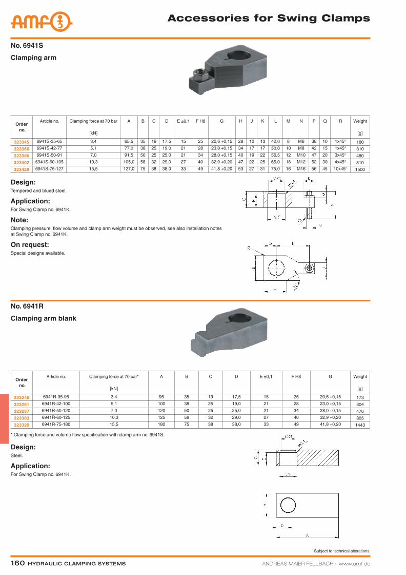
Clamping armNo. 6941S
Design:Tempered and blued steel.
Application:For Swing Clamp no. 6941K.
Note:Clamping pressure, flow volume and clamp arm weight must be observed, see also installation notes at Swing Clamp no. 6941K.
On request:Special designs available.
Clamping arm blankNo. 6941R
Design:Steel.
Application:For Swing Clamp no. 6941K.
* Clamping force and volume flow specification with clamp arm no. 6941S.
Order no.
Article no. Clamping force at 70 bar
[kN]
A B C D E ±0,1 F H8 G H J K L M N P Q R Weight
[g]
323345 6941S-35-65 3,4 65,5 35 19 17,5 15 25 20,6 +0,15 28 12 13 42,0 8 M6 38 10 1x45° 180323360 6941S-42-77 5,1 77,0 38 25 19,0 21 28 23,0 +0,15 34 17 17 50,0 10 M8 42 15 1x45° 310323386 6941S-50-91 7,0 91,5 50 25 25,0 21 34 28,0 +0,15 40 19 22 56,5 12 M10 47 20 3x45° 480323402 6941S-60-105 10,3 105,0 58 32 29,0 27 40 32,9 +0,20 47 22 25 65,0 16 M12 52 30 4x45° 810323428 6941S-75-127 15,5 127,0 75 38 38,0 33 49 41,8 +0,20 53 27 31 75,0 16 M16 56 45 10x45° 1500
Order no.
Article no. Clamping force at 70 bar*
[kN]
A B C D E ±0,1 F H8 G Weight
[g]
323246 6941R-35-95 3,4 95 35 19 17,5 15 25 20,6 +0,15 173323261 6941R-42-100 5,1 100 38 25 19,0 21 28 23,0 +0,15 304323287 6941R-50-120 7,0 120 50 25 25,0 21 34 28,0 +0,15 476323303 6941R-60-125 10,3 125 58 32 29,0 27 40 32,9 +0,20 805323329 6941R-75-180 15,5 180 75 38 38,0 33 49 41,8 +0,20 1443
Katalog_2012_Hydraulik_EN_ohnePreise.indd 160 3/28/2013 8:36:42 AM
Subject to technical alterations.
ANDREAS MAIER FELLBACH ∙ www.amf.de Hydraulic clamping SyStemS 161
Swing Clamp
Katalog_2012_Hydraulik_EN_ohnePreise.indd 161 3/28/2013 8:36:45 AM
162 Hydraulic clamping SyStemS ANDREAS MAIER FELLBACH ∙ www.amf.de
Subject to technical alterations.
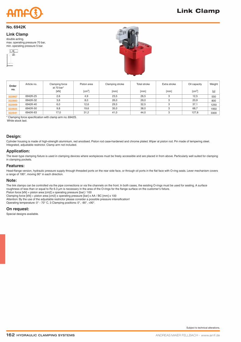
double acting, max. operating pressure 70 bar, min. operating pressure 5 bar.
Link ClampNo. 6942K
Link Clamp
Design:Cylinder housing is made of high-strength aluminium, red anodised. Piston rod case-hardened and chrome plated. Wiper at piston rod. Pin made of tempering steel. Integrated, adjustable restrictor. Clamp arm not included.
Application:The lever-type clamping fixture is used in clamping devices where workpieces must be freely accessible and are placed in from above. Particularly well suited for clamping in clamping pockets.
Features:Head-flange version, hydraulic pressure supply through threaded ports on the rear side face, or through oil ports in the flat face with O-ring seals. Lever mechanism covers a range of 180°, moving 90° in each direction.
Note:The link clamps can be controlled via the pipe connections or via the channels on the front. In both cases, the existing O-rings must be used for sealing. A surface roughness of less than or equal to Rz 6.3 µm is necessary in the area of the O-rings for the flange surface on the customer‘s fixture. Piston force [kN] = piston area [cm2] x operating pressure [bar] / 100 Clamping force [kN] = piston area [cm2] x operating pressure [bar] x AA / BC [mm] x 100 Attention: By the use of the adjustable restrictor please consider a possible pressure intensification! Operating temperature: 0° - 70° C, 3 Clamping positions: 0°, -90°, +90°.
On request:Special designs available.
* Clamping force specification with clamp arm no. 6942S. While stock last.
Order no.
Article no. Clamping force at 70 bar*
[kN]
Piston area
[cm²]
Clamping stroke
[mm]
Total stroke
[mm]
Extra stroke
[mm]
Oil capacity
[cm³]
Weight
[g]
322867 6942K-25 2,6 4,9 23,5 26,5 3 12,5 550322883 6942K-32 3,6 8,0 26,0 29,0 3 20,9 800322909 6942K-40 6,0 12,6 29,5 32,5 3 37,1 1250322925 6942K-50 9,8 19,6 35,0 38,0 3 68,7 1950322941 6942K-63 17,0 31,2 41,0 44,0 3 127,8 3300
Katalog_2012_Hydraulik_EN_ohnePreise.indd 162 3/28/2013 8:36:50 AM
ANDREAS MAIER FELLBACH ∙ www.amf.de Hydraulic clamping SyStemS 163
Subject to technical alterations.
Article no. A B C +0,3/0 D max. E F G H
6942K-25 40 M 5 48 45 30,0 22 3 486942K-32 47 M 6 55 50 33,5 24 3 606942K-40 55 M 6 65 60 39,5 30 5 646942K-50 63 M 8 75 70 45,0 32 5 726942K-63 75 M10 90 85 52,5 37 5 89
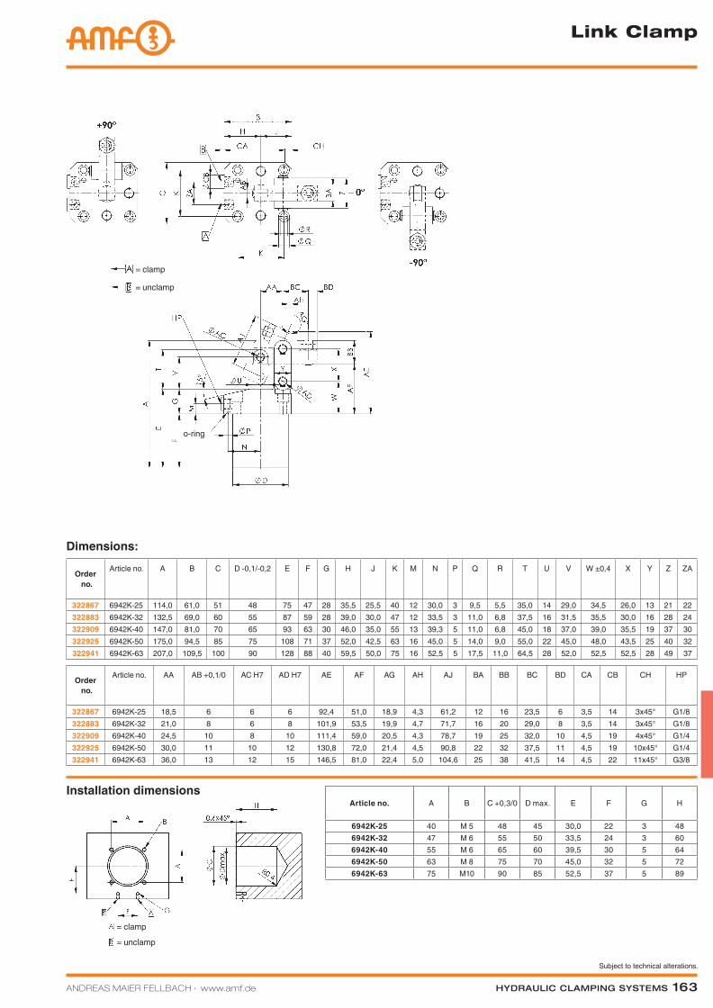
Installation dimensions
Link Clamp
Dimensions:
Order no.
Article no. A B C D -0,1/-0,2 E F G H J K M N P Q R T U V W ±0,4 X Y Z ZA
322867 6942K-25 114,0 61,0 51 48 75 47 28 35,5 25,5 40 12 30,0 3 9,5 5,5 35,0 14 29,0 34,5 26,0 13 21 22322883 6942K-32 132,5 69,0 60 55 87 59 28 39,0 30,0 47 12 33,5 3 11,0 6,8 37,5 16 31,5 35,5 30,0 16 28 24322909 6942K-40 147,0 81,0 70 65 93 63 30 46,0 35,0 55 13 39,3 5 11,0 6,8 45,0 18 37,0 39,0 35,5 19 37 30322925 6942K-50 175,0 94,5 85 75 108 71 37 52,0 42,5 63 16 45,0 5 14,0 9,0 55,0 22 45,0 48,0 43,5 25 40 32322941 6942K-63 207,0 109,5 100 90 128 88 40 59,5 50,0 75 16 52,5 5 17,5 11,0 64,5 28 52,0 52,5 52,5 28 49 37
Order no.
Article no. AA AB +0,1/0 AC H7 AD H7 AE AF AG AH AJ BA BB BC BD CA CB CH HP
322867 6942K-25 18,5 6 6 6 92,4 51,0 18,9 4,3 61,2 12 16 23,5 6 3,5 14 3x45° G1/8322883 6942K-32 21,0 8 6 8 101,9 53,5 19,9 4,7 71,7 16 20 29,0 8 3,5 14 3x45° G1/8322909 6942K-40 24,5 10 8 10 111,4 59,0 20,5 4,3 78,7 19 25 32,0 10 4,5 19 4x45° G1/4322925 6942K-50 30,0 11 10 12 130,8 72,0 21,4 4,5 90,8 22 32 37,5 11 4,5 19 10x45° G1/4322941 6942K-63 36,0 13 12 15 146,5 81,0 22,4 5,0 104,6 25 38 41,5 14 4,5 22 11x45° G3/8
= clamp
= unclamp
= clamp
= unclamp
o-ring
Katalog_2012_Hydraulik_EN_ohnePreise.indd 163 3/28/2013 8:36:53 AM

164 Hydraulic clamping SyStemS ANDREAS MAIER FELLBACH ∙ www.amf.de
Subject to technical alterations.
Clamping armNo. 6942S
Design:Tempered and blued steel.
Application:For Link Clamp no. 6942K.
Note:Clamping pressure, flow volume and clamp arm weight must be observed, see also installation notes at Link Clamp no. 6942K.
On request:Special designs available.
Design:Steel.
Application:For Link Clamp no. 6942K.
Clamping arm, blankNo. 6942R
While stock last.
* Clamping force specification with clamp arm no. 6942S. While stock last.
Order no.
Article no. Clamping force at 70 bar
[kN]
A B 0/-
0,3
C D
+0,1/0
E G H J K L M N P Q R S T H7 U H7 Weight
[g]
323279 6942S-25-54 2,6 54,0 12 16 6 16,0 13,0 13 8 18 10 M6 6 18,5 23,5 6 3,5 6 6 65323295 6942S-32-64 3,6 64,0 16 20 8 16,5 13,0 17 10 22 15 M8 6 21,0 29,0 6 6,0 6 8 130323311 6942S-40-74 6,0 74,5 19 25 10 21,0 17,5 22 13 27 20 M10 8 24,5 32,0 8 7,5 8 10 220323337 6942S-50-88 9,8 88,5 22 32 11 25,5 22,0 25 16 31 30 M12 10 30,0 37,5 10 9,5 10 12 380323352 6942S-63-102 17,0 102,5 25 38 13 30,5 26,0 31 22 40 45 M16 11 36,0 41,5 11 13,0 12 15 600
Order no.
Article no. Clamping force at 70 bar*
[kN]
A B 0/-0,3 C D +0,1/0 E G N P R S T H7 U H7 Weight
[g]
323170 6942R-25-85 2,6 85 12 16 6 16,0 13,0 6 18,5 6 3,5 6 6 61323196 6942R-32-90 3,6 90 16 20 8 16,5 13,0 6 21,0 6 6,0 6 8 124323212 6942R-40-105 6,0 105 19 25 10 21,0 17,5 8 24,5 8 7,5 8 10 207323238 6942R-50-110 9,8 110 22 32 11 25,5 22,0 10 30,0 10 9,5 10 12 367323253 6942R-63-180 17,0 160 25 38 13 30,5 26,0 11 36,0 11 13,0 12 15 575
Accessories for Link Clamps
Katalog_2012_Hydraulik_EN_ohnePreise.indd 164 3/28/2013 8:36:57 AM
ANDREAS MAIER FELLBACH ∙ www.amf.de Hydraulic clamping SyStemS 165
Subject to technical alterations.
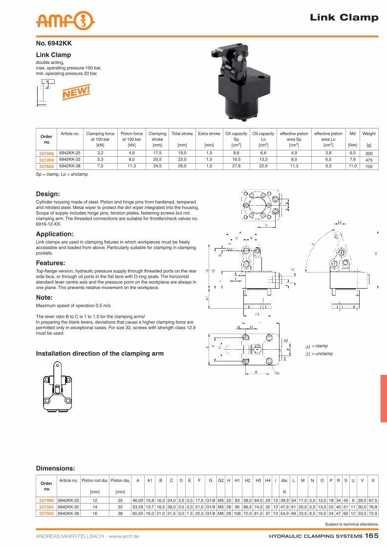
double acting, max. operating pressure 100 bar, min. operating pressure 20 bar.
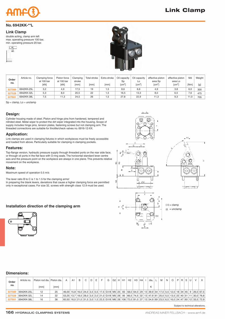
Link ClampNo. 6942KK
Order no.
Article no. Clamping force at 100 bar
[kN]
Piston force at 100 bar
[kN]
Clamping stroke[mm]
Total stroke
[mm]
Extra stroke
[mm]
Oil capacity Sp
[cm³]
Oil capacity Lo
[cm³]
effective piston area Sp
[cm²]
effective piston area Lo
[cm²]
Md
[Nm]
Weight
[g]
327486 6942KK-25 3,2 4,9 17,5 19,0 1,5 8,6 6,6 4,9 3,8 6,0 300327494 6942KK-32 5,3 8,0 20,5 22,0 1,5 16,5 13,3 8,0 6,5 7,6 475327502 6942KK-38 7,5 11,3 24,5 26,0 1,5 27,8 22,9 11,3 9,3 11,0 705
Design:Cylinder housing made of steel. Piston and hinge pins from hardened, tempered and nitrided steel. Metal wiper to protect the dirt wiper integrated into the housing. Scope of supply includes hinge pins, tension plates, fastening screws but not clamping arm. The threaded connections are suitable for throttle/check valves no. 6916-12-XX.
Application:Link clamps are used in clamping fixtures in which workpieces must be freely accessible and loaded from above. Particularly suitable for clamping in clamping pockets.
Features:Top-flange version, hydraulic pressure supply through threaded ports on the rear side face, or through oil ports in the flat face with O-ring seals. The horizontal standard lever centre axis and the pressure point on the workpiece are always in one plane. This prevents relative movement on the workpiece.
Note:Maximum speed of operation 0.5 m/s
The lever ratio B to C is 1 to 1.5 for the clamping arms! In preparing the blank levers, deviations that cause a higher clamping force are permitted only in exceptional cases. For size 32, screws with strength class 12.9 must be used.
Sp = clamp, Lo = unclamp
Dimensions:
Order no.
Article no. Piston rod dia.
[mm]
Piston dia.
[mm]
A A1 B C D E F G G2 H H1 H2 H3 H4 I dia.
K
L M N O P R S U V X
327486 6942KK-25 12 25 46,00 15,8 16,0 24,0 3,5 0,5 17,5 G1/8 M5 25 83 58,0 64,0 29 13 39,9 54 17,0 5,5 12,0 18 34 45 9 26,0 67,5327494 6942KK-32 14 32 53,25 13,7 18,5 28,0 3,5 2,0 21,0 G1/8 M5 28 95 66,5 74,5 32 13 47,9 61 20,0 5,5 13,5 22 40 51 11 30,0 76,8327502 6942KK-38 16 38 60,50 16,0 21,0 31,5 3,0 1,5 22,5 G1/8 M6 28 106 72,0 81,0 37 13 54,9 69 23,5 6,5 16,0 24 47 60 12 33,5 72,9
Link Clamp
Installation direction of the clamping arm= clamp = unclamp
NEW!
Katalog_2012_Hydraulik_EN_ohnePreise.indd 165 3/28/2013 8:37:04 AM
166 Hydraulic clamping SyStemS ANDREAS MAIER FELLBACH ∙ www.amf.de
Subject to technical alterations.
double acting, clamp arm leftmax. operating pressure 100 bar, min. operating pressure 20 bar.
Link ClampNo. 6942KK-**L
Order no.
Article no. Clamping force at 100 bar
[kN]
Piston force at 100 bar
[kN]
Clamping stroke[mm]
Total stroke
[mm]
Extra stroke
[mm]
Oil capacity Sp
[cm³]
Oil capacity Lo
[cm³]
effective piston area Sp
[cm²]
effective piston area Lo
[cm²]
Md
[Nm]
Weight
[g]
327569 6942KK-25L 3,2 4,9 17,5 19 1,5 8,6 6,6 4,9 3,8 6,0 300327528 6942KK-32L 5,3 8,0 20,5 22 1,5 16,5 13,3 8,0 6,5 7,6 475327601 6942KK-38L 7,5 11,3 24,5 26 1,5 27,8 22,9 11,3 9,3 11,0 705
Dimensions:
Order no.
Article no. Piston rod dia.
[mm]
Piston dia.
[mm]
A A1 B C D E F G G2 H H1 H2 H3 H4 I dia.
K
L M N O P R S U V X
327569 6942KK-25L 12 25 46,00 15,8 16,0 24,0 3,5 0,5 17,5 G1/8 M5 25 83 58,0 64,0 29 13 39,9 54 17,0 5,5 12,0 18 34 45 9 26,0 67,5327528 6942KK-32L 14 32 53,25 13,7 18,5 28,0 3,5 2,0 21,0 G1/8 M5 28 95 66,5 74,5 32 13 47,9 61 20,0 5,5 13,5 22 40 51 11 30,0 76,8327601 6942KK-38L 16 38 60,50 16,0 21,0 31,5 3,0 1,5 22,5 G1/8 M6 28 106 72,0 81,0 37 13 54,9 69 23,5 6,5 16,0 24 47 60 12 33,5 72,9
Design:Cylinder housing made of steel. Piston and hinge pins from hardened, tempered and nitrided steel. Metal wiper to protect the dirt wiper integrated into the housing. Scope of supply includes hinge pins, tension plates, fastening screws but not clamping arm. The threaded connections are suitable for throttle/check valves no. 6916-12-XX.
Application:Link clamps are used in clamping fixtures in which workpieces must be freely accessible and loaded from above. Particularly suitable for clamping in clamping pockets.
Features:Top-flange version, hydraulic pressure supply through threaded ports on the rear side face, or through oil ports in the flat face with O-ring seals. The horizontal standard lever centre axis and the pressure point on the workpiece are always in one plane. This prevents relative movement on the workpiece.
Note:Maximum speed of operation 0.5 m/s
The lever ratio B to C is 1 to 1.5 for the clamping arms! In preparing the blank levers, deviations that cause a higher clamping force are permitted only in exceptional cases. For size 32, screws with strength class 12.9 must be used.
Sp = clamp, Lo = unclamp
Link Clamp
Installation direction of the clamping arm = clamp = unclamp
Katalog_2012_Hydraulik_EN_ohnePreise.indd 166 3/28/2013 8:37:09 AM
ANDREAS MAIER FELLBACH ∙ www.amf.de Hydraulic clamping SyStemS 167
Subject to technical alterations.
double acting, clamp arm rightmax. operating pressure 100 bar, min. operating pressure 20 bar.
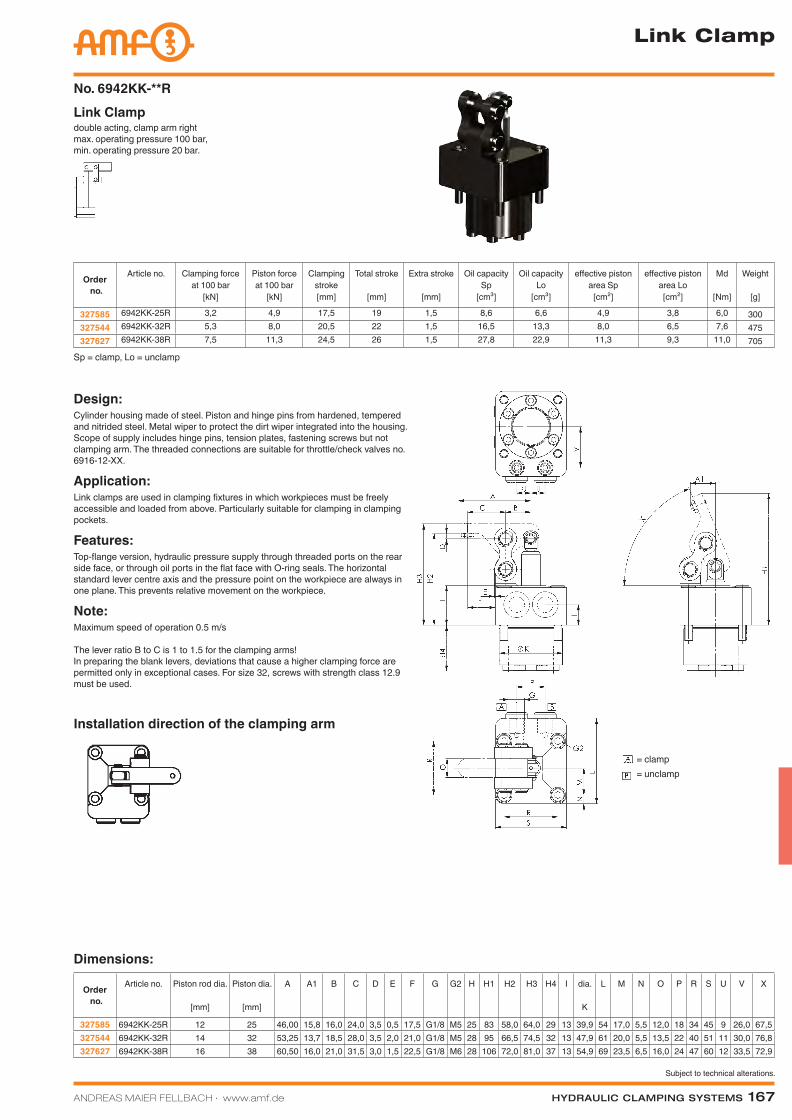
Link ClampNo. 6942KK-**R
Order no.
Article no. Clamping force at 100 bar
[kN]
Piston force at 100 bar
[kN]
Clamping stroke[mm]
Total stroke
[mm]
Extra stroke
[mm]
Oil capacity Sp
[cm³]
Oil capacity Lo
[cm³]
effective piston area Sp
[cm²]
effective piston area Lo
[cm²]
Md
[Nm]
Weight
[g]
327585 6942KK-25R 3,2 4,9 17,5 19 1,5 8,6 6,6 4,9 3,8 6,0 300327544 6942KK-32R 5,3 8,0 20,5 22 1,5 16,5 13,3 8,0 6,5 7,6 475327627 6942KK-38R 7,5 11,3 24,5 26 1,5 27,8 22,9 11,3 9,3 11,0 705
Dimensions:
Order no.
Article no. Piston rod dia.
[mm]
Piston dia.
[mm]
A A1 B C D E F G G2 H H1 H2 H3 H4 I dia.
K
L M N O P R S U V X
327585 6942KK-25R 12 25 46,00 15,8 16,0 24,0 3,5 0,5 17,5 G1/8 M5 25 83 58,0 64,0 29 13 39,9 54 17,0 5,5 12,0 18 34 45 9 26,0 67,5327544 6942KK-32R 14 32 53,25 13,7 18,5 28,0 3,5 2,0 21,0 G1/8 M5 28 95 66,5 74,5 32 13 47,9 61 20,0 5,5 13,5 22 40 51 11 30,0 76,8327627 6942KK-38R 16 38 60,50 16,0 21,0 31,5 3,0 1,5 22,5 G1/8 M6 28 106 72,0 81,0 37 13 54,9 69 23,5 6,5 16,0 24 47 60 12 33,5 72,9
Design:Cylinder housing made of steel. Piston and hinge pins from hardened, tempered and nitrided steel. Metal wiper to protect the dirt wiper integrated into the housing. Scope of supply includes hinge pins, tension plates, fastening screws but not clamping arm. The threaded connections are suitable for throttle/check valves no. 6916-12-XX.
Application:Link clamps are used in clamping fixtures in which workpieces must be freely accessible and loaded from above. Particularly suitable for clamping in clamping pockets.
Features:Top-flange version, hydraulic pressure supply through threaded ports on the rear side face, or through oil ports in the flat face with O-ring seals. The horizontal standard lever centre axis and the pressure point on the workpiece are always in one plane. This prevents relative movement on the workpiece.
Note:Maximum speed of operation 0.5 m/s
The lever ratio B to C is 1 to 1.5 for the clamping arms! In preparing the blank levers, deviations that cause a higher clamping force are permitted only in exceptional cases. For size 32, screws with strength class 12.9 must be used.
Sp = clamp, Lo = unclamp
Link Clamp
Installation direction of the clamping arm
= clamp = unclamp
Katalog_2012_Hydraulik_EN_ohnePreise.indd 167 3/28/2013 8:37:14 AM
168 Hydraulic clamping SyStemS ANDREAS MAIER FELLBACH ∙ www.amf.de
Subject to technical alterations.
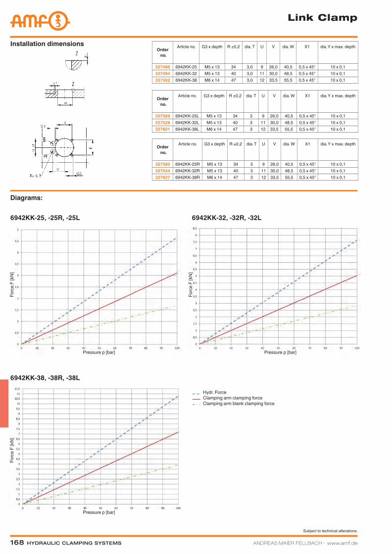
Diagrams:
6942KK-25, -25R, -25L 6942KK-32, -32R, -32L
6942KK-38, -38R, -38L
Link Clamp
Hydr. ForceClamping arm clamping forceClamping arm blank clamping force
Pressure p [bar]
Forc
e F
[kN
]
Forc
e F
[kN
]Fo
rce
F [k
N]
Pressure p [bar]
Pressure p [bar]
Order no.
Article no. G3 x depth R ±0,2 dia. T U V dia. W X1 dia. Y x max. depth
327569 6942KK-25L M5 x 13 34 3 9 26,0 40,5 0,5 x 45° 10 x 0,1327528 6942KK-32L M5 x 13 40 3 11 30,0 48,5 0,5 x 45° 10 x 0,1327601 6942KK-38L M6 x 14 47 3 12 33,5 55,5 0,5 x 45° 10 x 0,1
Installation dimensions
Order no.
Article no. G3 x depth R ±0,2 dia. T U V dia. W X1 dia. Y x max. depth
327585 6942KK-25R M5 x 13 34 3 9 26,0 40,5 0,5 x 45° 10 x 0,1327544 6942KK-32R M5 x 13 40 3 11 30,0 48,5 0,5 x 45° 10 x 0,1327627 6942KK-38R M6 x 14 47 3 12 33,5 55,5 0,5 x 45° 10 x 0,1
Order no.
Article no. G3 x depth R ±0,2 dia. T U V dia. W X1 dia. Y x max. depth
327486 6942KK-25 M5 x 13 34 3,0 9 26,0 40,5 0,5 x 45° 10 x 0,1327494 6942KK-32 M5 x 13 40 3,0 11 30,0 48,5 0,5 x 45° 10 x 0,1327502 6942KK-38 M6 x 14 47 3,0 12 33,5 55,5 0,5 x 45° 10 x 0,1
Katalog_2012_Hydraulik_EN_ohnePreise.indd 168 3/28/2013 8:37:34 AM
ANDREAS MAIER FELLBACH ∙ www.amf.de Hydraulic clamping SyStemS 169
Subject to technical alterations.
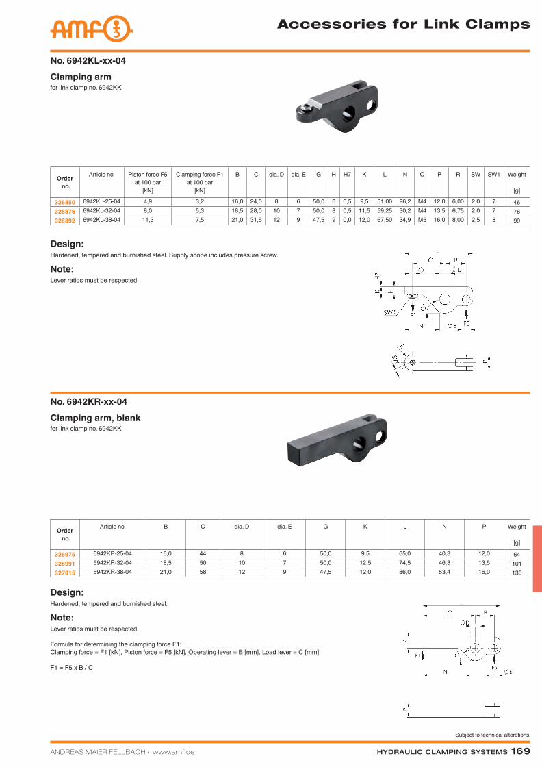
for link clamp no. 6942KKClamping armNo. 6942KL-xx-04
for link clamp no. 6942KKClamping arm, blankNo. 6942KR-xx-04
Design:Hardened, tempered and burnished steel.
Note:Lever ratios must be respected.
Formula for determining the clamping force F1:Clamping force = F1 [kN], Piston force = F5 [kN], Operating lever = B [mm], Load lever = C [mm]
F1 = F5 x B / C
Design:Hardened, tempered and burnished steel. Supply scope includes pressure screw.
Note:Lever ratios must be respected.
Accessories for Link Clamps
Order no.
Article no. Piston force F5 at 100 bar
[kN]
Clamping force F1 at 100 bar
[kN]
B C dia. D dia. E G H H7 K L N O P R SW SW1 Weight
[g]
326850 6942KL-25-04 4,9 3,2 16,0 24,0 8 6 50,0 6 0,5 9,5 51,00 26,2 M4 12,0 6,00 2,0 7 46326876 6942KL-32-04 8,0 5,3 18,5 28,0 10 7 50,0 8 0,5 11,5 59,25 30,2 M4 13,5 6,75 2,0 7 76326892 6942KL-38-04 11,3 7,5 21,0 31,5 12 9 47,5 9 0,0 12,0 67,50 34,9 M5 16,0 8,00 2,5 8 99
Order no.
Article no. B C dia. D dia. E G K L N P Weight
[g]
326975 6942KR-25-04 16,0 44 8 6 50,0 9,5 65,0 40,3 12,0 64326991 6942KR-32-04 18,5 50 10 7 50,0 12,5 74,5 46,3 13,5 101327015 6942KR-38-04 21,0 58 12 9 47,5 12,0 86,0 53,4 16,0 130
Katalog_2012_Hydraulik_EN_ohnePreise.indd 169 3/28/2013 8:37:37 AM
170 Hydraulic clamping SyStemS ANDREAS MAIER FELLBACH ∙ www.amf.de
Subject to technical alterations.
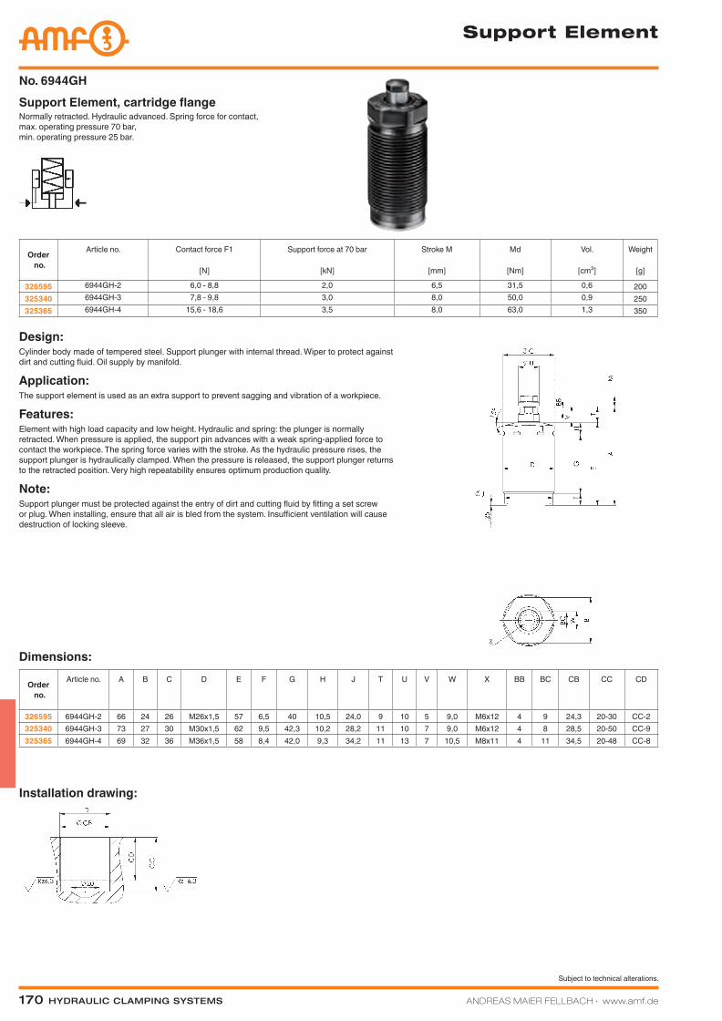
Support Element
Normally retracted. Hydraulic advanced. Spring force for contact, max. operating pressure 70 bar, min. operating pressure 25 bar.
Support Element, cartridge flangeNo. 6944GH
Dimensions:
Order no.
Article no. A B C D E F G H J T U V W X BB BC CB CC CD
326595 6944GH-2 66 24 26 M26x1,5 57 6,5 40 10,5 24,0 9 10 5 9,0 M6x12 4 9 24,3 20-30 CC-2325340 6944GH-3 73 27 30 M30x1,5 62 9,5 42,3 10,2 28,2 11 10 7 9,0 M6x12 4 8 28,5 20-50 CC-9325365 6944GH-4 69 32 36 M36x1,5 58 8,4 42,0 9,3 34,2 11 13 7 10,5 M8x11 4 11 34,5 20-48 CC-8
Design:Cylinder body made of tempered steel. Support plunger with internal thread. Wiper to protect against dirt and cutting fluid. Oil supply by manifold.
Application:The support element is used as an extra support to prevent sagging and vibration of a workpiece.
Features:Element with high load capacity and low height. Hydraulic and spring: the plunger is normally retracted. When pressure is applied, the support pin advances with a weak spring-applied force to contact the workpiece. The spring force varies with the stroke. As the hydraulic pressure rises, the support plunger is hydraulically clamped. When the pressure is released, the support plunger returns to the retracted position. Very high repeatability ensures optimum production quality.
Note:Support plunger must be protected against the entry of dirt and cutting fluid by fitting a set screw or plug. When installing, ensure that all air is bled from the system. Insufficient ventilation will cause destruction of locking sleeve.
Order no.
Article no. Contact force F1
[N]
Support force at 70 bar
[kN]
Stroke M
[mm]
Md
[Nm]
Vol.
[cm³]
Weight
[g]
326595 6944GH-2 6,0 - 8,8 2,0 6,5 31,5 0,6 200325340 6944GH-3 7,8 - 9,8 3,0 8,0 50,0 0,9 250325365 6944GH-4 15,6 - 18,6 3,5 8,0 63,0 1,3 350
Installation drawing:
Katalog_2012_Hydraulik_EN_ohnePreise.indd 170 3/28/2013 8:37:42 AM
Subject to technical alterations.
ANDREAS MAIER FELLBACH ∙ www.amf.de Hydraulic clamping SyStemS 171
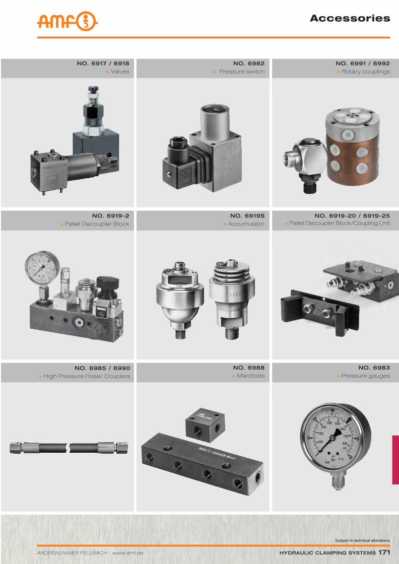
no. 6985 / 6990> High Pressure Hose/ Couplers
no. 6988 > Manifolds
no. 6983 > Pressure gauges
Accessories
no. 6919-2 > Pallet Decoupler Block
no. 6919S > Accumulator
no. 6919-20 / 6919-25> Pallet Decoupler Block/Coupling Unit
no. 6917 / 6918 > Valves
no. 6982 > Pressure switch
no. 6991 / 6992 > Rotary couplings
Katalog_2012_Hydraulik_EN_ohnePreise.indd 171 3/28/2013 8:37:50 AM
172 Hydraulic clamping SyStemS ANDREAS MAIER FELLBACH ∙ www.amf.de
Subject to technical alterations.
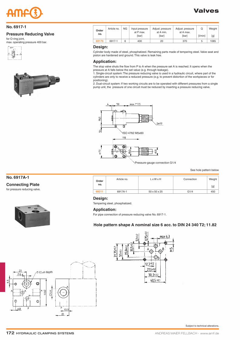
for O-ring joint, max. operating pressure 400 bar.
Pressure Reducing ValveNo. 6917-1
Order no.
Article no. NG Input pressure at P max.
[bar]
Adjust. pressure at A min.
[bar]
Adjust. pressure at A max.
[bar]
Q
[l/min]
Weight
[g]
69179 6917-1 6 400 20 370 5 1085
Valves
ISO 4762 M5x60
Pressure-gauge connection G1/4
See hole pattern below
depth
Hole pattern shape A nominal size 6 acc. to DIN 24 340 T2; 11.82
Design:Cylinder body made of steel, phosphatized. Remaining parts made of tempering steel. Valve seat and piston are hardened and ground. This valve is leak free.
Application:The stop valve shuts the flow from P to A when the pressure set A is reached. It opens when the pressure at A falls below the set value (e.g. through leakage). 1. Single-circuit system: The pressure reducing valve is used in a hydraulic circuit, where part of the cylinders are only to receive a reduced pressure (e.g. to prevent distortion of the workpieces or for positioning). 2. Dual-circuit system: If two working circuits are to be operated with different pressures from a single pump unit, the pressure of one circuit must be reduced by inserting a pressure reducing valve.
for pressure reducing valve.Connecting PlateNo. 6917A-1
Order no.
Article no. L x W x H Connection Weight
[g]
69211 6917A-1 50 x 50 x 25 G1/4 450
Design:Tempering steel, phosphatized.
Application:For pipe connection of pressure reducing valve No. 6917-1.
Katalog_2012_Hydraulik_EN_ohnePreise.indd 172 3/28/2013 8:37:53 AM
ANDREAS MAIER FELLBACH ∙ www.amf.de Hydraulic clamping SyStemS 173
Subject to technical alterations.
Valves
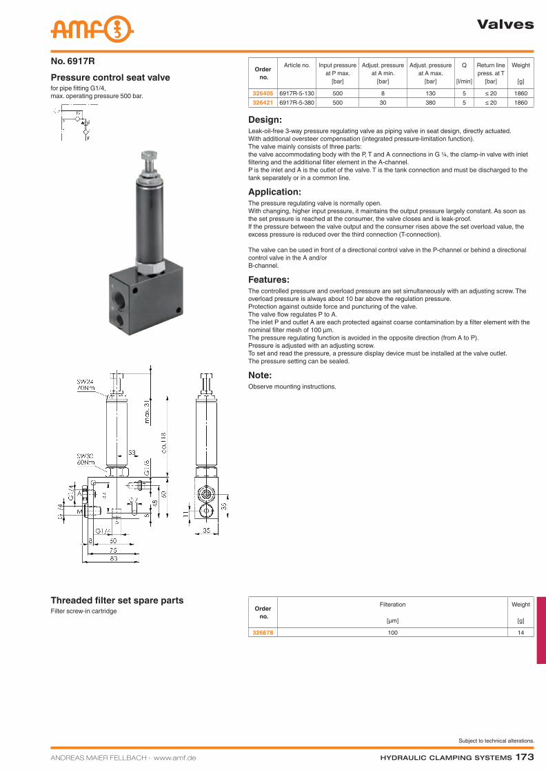
for pipe fitting G1/4, max. operating pressure 500 bar.
Pressure control seat valveNo. 6917R
Order no.
Article no. Input pressure at P max.
[bar]
Adjust. pressure at A min.
[bar]
Adjust. pressure at A max.
[bar]
Q
[l/min]
Return line press. at T
[bar]
Weight
[g]
326405 6917R-5-130 500 8 130 5 ≤ 20 1860326421 6917R-5-380 500 30 380 5 ≤ 20 1860
Design:Leak-oil-free 3-way pressure regulating valve as piping valve in seat design, directly actuated. With additional oversteer compensation (integrated pressure-limitation function). The valve mainly consists of three parts: the valve accommodating body with the P, T and A connections in G ¼, the clamp-in valve with inlet filtering and the additional filter element in the A-channel. P is the inlet and A is the outlet of the valve. T is the tank connection and must be discharged to the tank separately or in a common line.
Application:The pressure regulating valve is normally open. With changing, higher input pressure, it maintains the output pressure largely constant. As soon as the set pressure is reached at the consumer, the valve closes and is leak-proof. If the pressure between the valve output and the consumer rises above the set overload value, the excess pressure is reduced over the third connection (T-connection). The valve can be used in front of a directional control valve in the P-channel or behind a directional control valve in the A and/or B-channel.
Features:The controlled pressure and overload pressure are set simultaneously with an adjusting screw. The overload pressure is always about 10 bar above the regulation pressure. Protection against outside force and puncturing of the valve. The valve flow regulates P to A. The inlet P and outlet A are each protected against coarse contamination by a filter element with the nominal filter mesh of 100 µm. The pressure regulating function is avoided in the opposite direction (from A to P). Pressure is adjusted with an adjusting screw. To set and read the pressure, a pressure display device must be installed at the valve outlet. The pressure setting can be sealed.
Note:Observe mounting instructions.
Order no.
Filteration
[µm]
Weight
[g]
326678 100 14
Filter screw-in cartridgeThreaded filter set spare parts
Katalog_2012_Hydraulik_EN_ohnePreise.indd 173 3/28/2013 8:37:56 AM
174 Hydraulic clamping SyStemS ANDREAS MAIER FELLBACH ∙ www.amf.de
Subject to technical alterations.
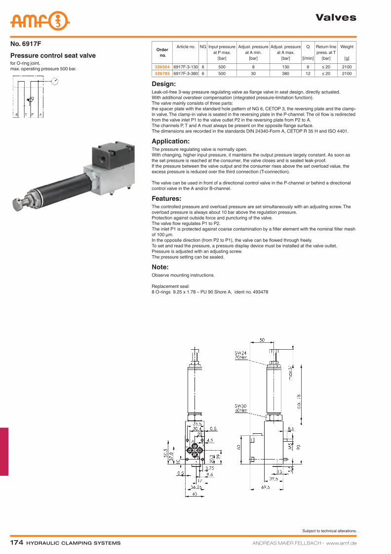
for O-ring joint, max. operating pressure 500 bar.
Pressure control seat valveNo. 6917F
Order no.
Article no. NG Input pressure at P max.
[bar]
Adjust. pressure at A min.
[bar]
Adjust. pressure at A max.
[bar]
Q
[l/min]
Return line press. at T
[bar]
Weight
[g]
326504 6917F-3-130 6 500 8 130 6 ≤ 20 2100326785 6917F-3-380 6 500 30 380 12 ≤ 20 2100
Valves
Design:Leak-oil-free 3-way pressure regulating valve as flange valve in seat design, directly actuated. With additional oversteer compensation (integrated pressure-limitation function). The valve mainly consists of three parts: the spacer plate with the standard hole pattern of NG 6, CETOP 3, the reversing plate and the clamp-in valve. The clamp-in valve is seated in the reversing plate in the P-channel. The oil flow is redirected from the valve inlet P1 to the valve outlet P2 in the reversing plate from P2 to A. The channels P, T and A must always be present on the opposite flange surface. The dimensions are recorded in the standards DIN 24340-Form A, CETOP R 35 H and ISO 4401.
Application:The pressure regulating valve is normally open. With changing, higher input pressure, it maintains the output pressure largely constant. As soon as the set pressure is reached at the consumer, the valve closes and is sealed leak-proof. If the pressure between the valve output and the consumer rises above the set overload value, the excess pressure is reduced over the third connection (T-connection). The valve can be used in front of a directional control valve in the P-channel or behind a directional control valve in the A and/or B-channel.
Features:The controlled pressure and overload pressure are set simultaneously with an adjusting screw. The overload pressure is always about 10 bar above the regulation pressure. Protection against outside force and puncturing of the valve. The valve flow regulates P1 to P2. The inlet P1 is protected against coarse contamination by a filter element with the nominal filter mesh of 100 µm. In the opposite direction (from P2 to P1), the valve can be flowed through freely. To set and read the pressure, a pressure display device must be installed at the valve outlet. Pressure is adjusted with an adjusting screw. The pressure setting can be sealed.
Note:Observe mounting instructions. Replacement seal: 8 O-rings 9.25 x 1.78 – PU 90 Shore A, ident no. 493478
Katalog_2012_Hydraulik_EN_ohnePreise.indd 174 3/28/2013 8:38:01 AM
ANDREAS MAIER FELLBACH ∙ www.amf.de Hydraulic clamping SyStemS 175
Subject to technical alterations.
Valves
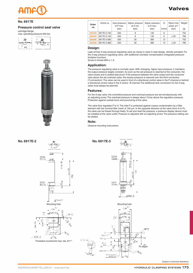
No. 6917E-2 No. 6917E-3
cartridge flange, max. operating pressure 500 bar.
Pressure control seat valveNo. 6917E
Order no.
Article no. Input pressure at P max.
[bar]
Adjust. pressure at A min.
[bar]
Adjust. pressure at A max.
[bar]
Q
[l/min]
Return line press. at T
[bar]
Weight
[g]
492330 6917E-2-130 500 8 130 6 - 752326462 6917E-3-130 500 8 130 6 ≤ 20 780326686 6917E-2-380 500 30 380 12 - 752326488 6917E-3-380 500 30 380 12 ≤ 20 780
Design:Leak-oil-free 3-way pressure regulating valve as clamp-in valve in seat design, directly actuated. For the 3-way pressure regulating valve, with additional oversteer compensation (integrated pressure-limitation function). Screw-in thread M24 x 1.5.
Application:The pressure regulating valve is normally open. With changing, higher input pressure, it maintains the output pressure largely constant. As soon as the set pressure is reached at the consumer, the valve closes and is sealed leak-proof. If the pressure between the valve output and the consumer rises above the set overload value, the excess pressure is reduced over the third connection (T-connection). The valve can be used in front of a directional control valve in the P-channel or behind a directional control valve in the A and/or B-channel.The additional tank connection for the 3-way valve must always be planned.
Features:For the 3-way valve, the controlled pressure and overload pressure are set simultaneously with an adjusting screw. The overload pressure is always about 10 bar above the regulation pressure. Protection against outside force and puncturing of the valve. The valve flow regulates P to A. The inlet P is protected against coarse contamination by a filter element with the nominal filter mesh of 100 µm. In the opposite direction at the valve (from A to P), the valve can be flowed through freely. To set and read the pressure, a pressure display device must be installed at the valve outlet. Pressure is adjusted with an adjusting screw. The pressure setting can be sealed.
Note:Observe mounting instructions.
Mounting hole
Threaded countersink max. dia. 24+0.2
Mounting hole
Fit depth
Katalog_2012_Hydraulik_EN_ohnePreise.indd 175 3/28/2013 8:38:07 AM
176 Hydraulic clamping SyStemS ANDREAS MAIER FELLBACH ∙ www.amf.de
Subject to technical alterations.
Valves
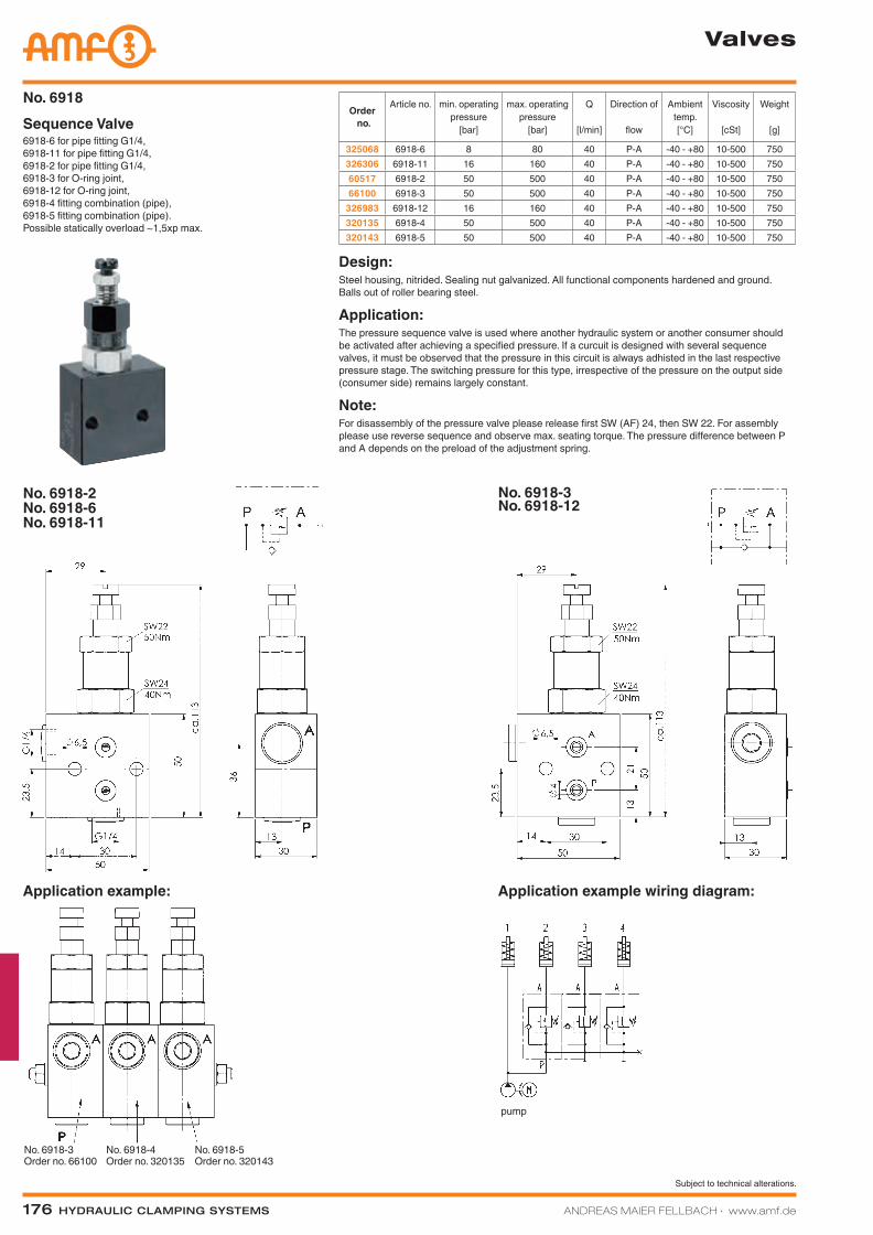
6918-6 for pipe fitting G1/4, 6918-11 for pipe fitting G1/4, 6918-2 for pipe fitting G1/4, 6918-3 for O-ring joint, 6918-12 for O-ring joint, 6918-4 fitting combination (pipe), 6918-5 fitting combination (pipe). Possible statically overload ~1,5xp max.
Sequence Valve No. 6918
Order no.
Article no. min. operating pressure
[bar]
max. operating pressure
[bar]
Q
[l/min]
Direction of
flow
Ambient temp.[°C]
Viscosity
[cSt]
Weight
[g]
325068 6918-6 8 80 40 P-A -40 - +80 10-500 750326306 6918-11 16 160 40 P-A -40 - +80 10-500 75060517 6918-2 50 500 40 P-A -40 - +80 10-500 75066100 6918-3 50 500 40 P-A -40 - +80 10-500 750
326983 6918-12 16 160 40 P-A -40 - +80 10-500 750320135 6918-4 50 500 40 P-A -40 - +80 10-500 750320143 6918-5 50 500 40 P-A -40 - +80 10-500 750
Design:Steel housing, nitrided. Sealing nut galvanized. All functional components hardened and ground. Balls out of roller bearing steel.
Application:The pressure sequence valve is used where another hydraulic system or another consumer should be activated after achieving a specified pressure. If a curcuit is designed with several sequence valves, it must be observed that the pressure in this circuit is always adhisted in the last respective pressure stage. The switching pressure for this type, irrespective of the pressure on the output side (consumer side) remains largely constant.
Note:For disassembly of the pressure valve please release first SW (AF) 24, then SW 22. For assembly please use reverse sequence and observe max. seating torque. The pressure difference between P and A depends on the preload of the adjustment spring.
No. 6918-2No. 6918-6No. 6918-11
No. 6918-3 No. 6918-12
Application example: Application example wiring diagram:
No. 6918-3 Order no. 66100
No. 6918-4 Order no. 320135
No. 6918-5 Order no. 320143
pump
Katalog_2012_Hydraulik_EN_ohnePreise.indd 176 3/28/2013 8:38:13 AM
ANDREAS MAIER FELLBACH ∙ www.amf.de Hydraulic clamping SyStemS 177
Subject to technical alterations.
Valves
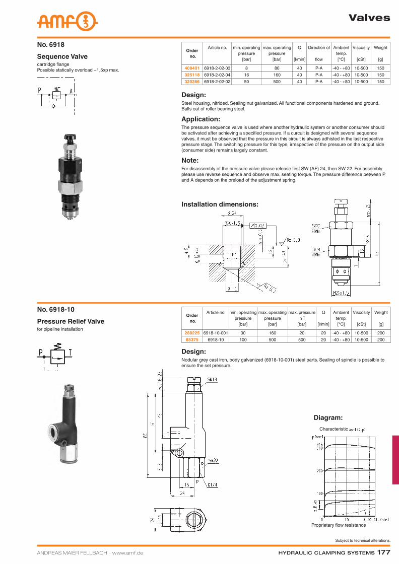
cartridge flange Possible statically overload ~1,5xp max.
Sequence Valve No. 6918
Order no.
Article no. min. operating pressure
[bar]
max. operating pressure
[bar]
Q
[l/min]
Direction of
flow
Ambient temp.[°C]
Viscosity
[cSt]
Weight
[g]
408401 6918-2-02-03 8 80 40 P-A -40 - +80 10-500 150325118 6918-2-02-04 16 160 40 P-A -40 - +80 10-500 150320366 6918-2-02-02 50 500 40 P-A -40 - +80 10-500 150
Design:Steel housing, nitrided. Sealing nut galvanized. All functional components hardened and ground. Balls out of roller bearing steel.
Application:The pressure sequence valve is used where another hydraulic system or another consumer should be activated after achieving a specified pressure. If a curcuit is designed with several sequence valves, it must be observed that the pressure in this circuit is always adhisted in the last respective pressure stage. The switching pressure for this type, irrespective of the pressure on the output side (consumer side) remains largely constant.
Note:For disassembly of the pressure valve please release first SW (AF) 24, then SW 22. For assembly please use reverse sequence and observe max. seating torque. The pressure difference between P and A depends on the preload of the adjustment spring.
Installation dimensions:
Diagram:
Design:Nodular grey cast iron, body galvanized (6918-10-001) steel parts. Sealing of spindle is possible to ensure the set pressure.
for pipeline installationPressure Relief ValveNo. 6918-10
Order no.
Article no. min. operating pressure
[bar]
max. operating pressure
[bar]
max. pressure in T[bar]
Q
[l/min]
Ambient temp.[°C]
Viscosity
[cSt]
Weight
[g]
288225 6918-10-001 30 160 20 20 -40 - +80 10-500 20065375 6918-10 100 500 500 20 -40 - +80 10-500 200
Proprietary flow resistance
Characteristic
Katalog_2012_Hydraulik_EN_ohnePreise.indd 177 3/28/2013 8:38:15 AM
178 Hydraulic clamping SyStemS ANDREAS MAIER FELLBACH ∙ www.amf.de
Subject to technical alterations.
Valves
Order no.
Article no. Q
[l/min]
Delay setting range
[s]
Direction of flow Weight
[g]
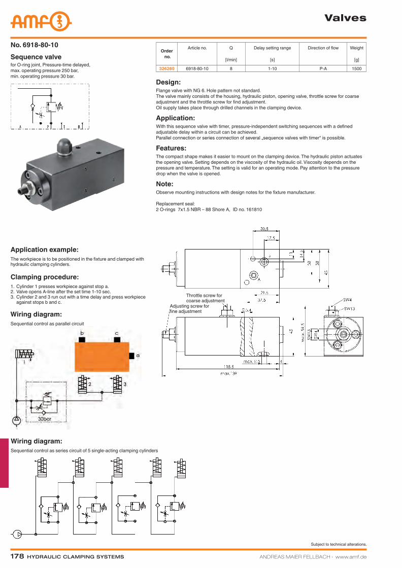
326280 6918-80-10 8 1-10 P-A 1500for O-ring joint, Pressure-time delayed, max. operating pressure 250 bar, min. operating pressure 30 bar.
Sequence valveNo. 6918-80-10
Design:Flange valve with NG 6. Hole pattern not standard. The valve mainly consists of the housing, hydraulic piston, opening valve, throttle screw for coarse adjustment and the throttle screw for find adjustment. Oil supply takes place through drilled channels in the clamping device.
Application:With this sequence valve with timer, pressure-independent switching sequences with a defined adjustable delay within a circuit can be achieved. Parallel connection or series connection of several „sequence valves with timer“ is possible.
Features:The compact shape makes it easier to mount on the clamping device. The hydraulic piston actuates the opening valve. Setting depends on the viscosity of the hydraulic oil. Viscosity depends on the pressure and temperature. The setting is valid for an operating mode. Pay attention to the pressure drop when the valve is opened.
Note:Observe mounting instructions with design notes for the fixture manufacturer. Replacement seal: 2 O-rings 7x1.5 NBR – 88 Shore A, ID no. 161810
Wiring diagram:Sequential control as series circuit of 5 single-acting clamping cylinders
Application example:The workpiece is to be positioned in the fixture and clamped with hydraulic clamping cylinders.
Clamping procedure:1. Cylinder 1 presses workpiece against stop a.2. Valve opens A-line after the set time 1-10 sec.3. Cylinder 2 and 3 run out with a time delay and press workpiece
against stops b and c.
Wiring diagram:Sequential control as parallel circuit
Throttle screw for coarse adjustment
Adjusting screw for fine adjustment
Katalog_2012_Hydraulik_EN_ohnePreise.indd 178 3/28/2013 8:38:23 AM
ANDREAS MAIER FELLBACH ∙ www.amf.de Hydraulic clamping SyStemS 179
Subject to technical alterations.
Valves
Diagram:
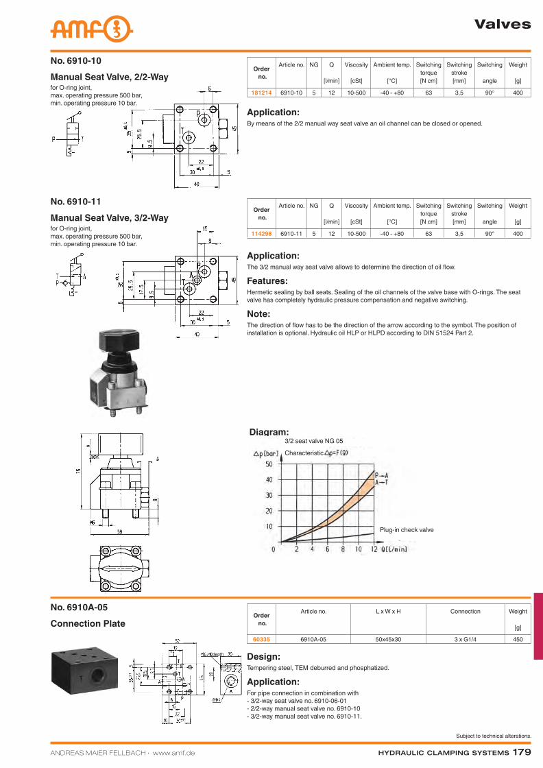
Connection PlateNo. 6910A-05
Order no.
Article no. L x W x H Connection Weight
[g]
60335 6910A-05 50x45x30 3 x G1/4 450
Design:Tempering steel, TEM deburred and phosphatized.
Application:For pipe connection in combination with - 3/2-way seat valve no. 6910-06-01 - 2/2-way manual seat valve no. 6910-10 - 3/2-way manual seat valve no. 6910-11.
for O-ring joint, max. operating pressure 500 bar, min. operating pressure 10 bar.
Manual Seat Valve, 2/2-WayNo. 6910-10
Order no.
Article no. NG Q
[l/min]
Viscosity
[cSt]
Ambient temp.
[°C]
Switching torque[N cm]
Switching stroke[mm]
Switching
angle
Weight
[g]
181214 6910-10 5 12 10-500 -40 - +80 63 3,5 90° 400
for O-ring joint, max. operating pressure 500 bar, min. operating pressure 10 bar.
Manual Seat Valve, 3/2-WayNo. 6910-11
Order no.
Article no. NG Q
[l/min]
Viscosity
[cSt]
Ambient temp.
[°C]
Switching torque[N cm]
Switching stroke[mm]
Switching
angle
Weight
[g]
114298 6910-11 5 12 10-500 -40 - +80 63 3,5 90° 400
Application:The 3/2 manual way seat valve allows to determine the direction of oil flow.
Features:Hermetic sealing by ball seats. Sealing of the oil channels of the valve base with O-rings. The seat valve has completely hydraulic pressure compensation and negative switching.
Note:The direction of flow has to be the direction of the arrow according to the symbol. The position of installation is optional. Hydraulic oil HLP or HLPD according to DIN 51524 Part 2.
Application:By means of the 2/2 manual way seat valve an oil channel can be closed or opened.
depth
Plug-in check valve
3/2 seat valve NG 05
Characteristic
Katalog_2012_Hydraulik_EN_ohnePreise.indd 179 3/28/2013 8:38:26 AM
Subject to technical alterations.
180 Hydraulic clamping SyStemS ANDREAS MAIER FELLBACH ∙ www.amf.de
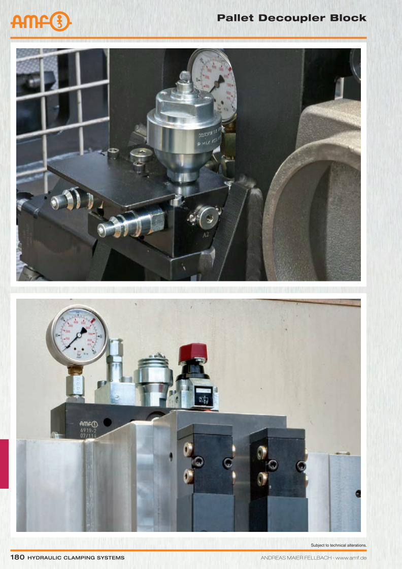
Pallet Decoupler block
Katalog_2012_Hydraulik_EN_ohnePreise.indd 180 3/28/2013 8:38:32 AM
Subject to technical alterations.
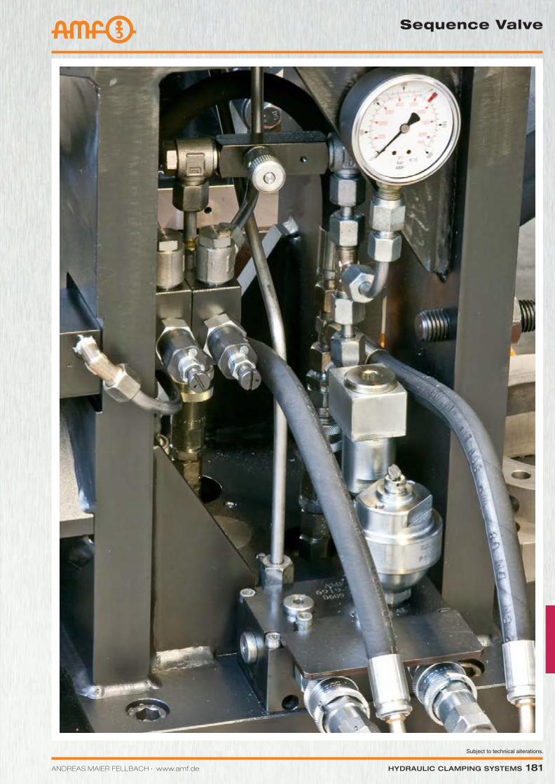
ANDREAS MAIER FELLBACH ∙ www.amf.de Hydraulic clamping SyStemS 181
Sequence Valve
Katalog_2012_Hydraulik_EN_ohnePreise.indd 181 3/28/2013 8:38:35 AM
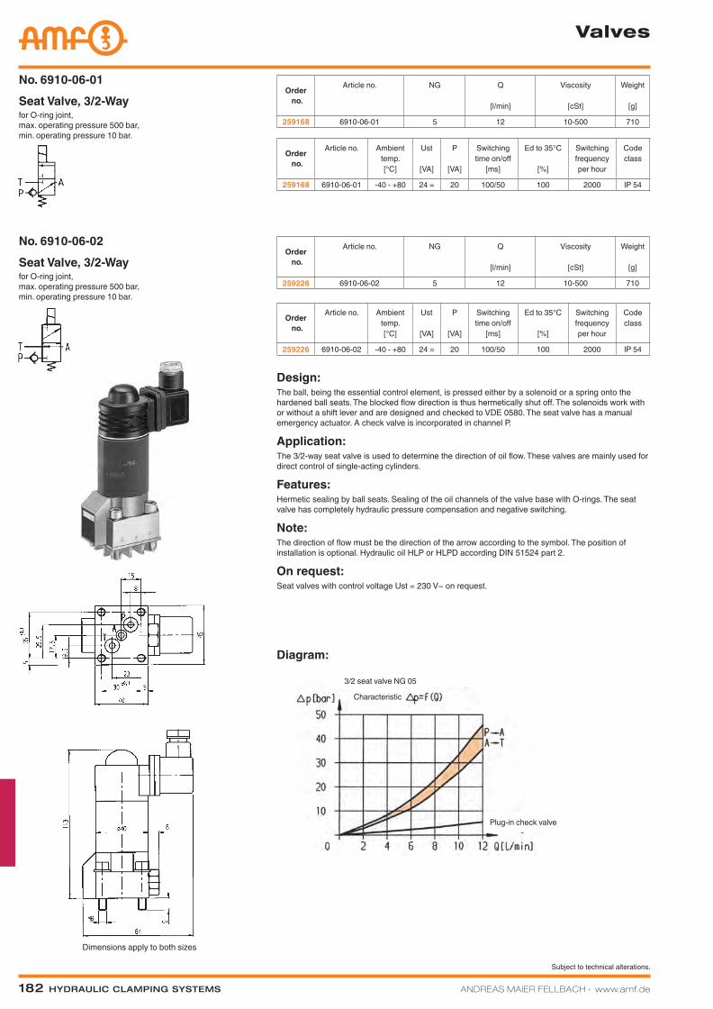
182 Hydraulic clamping SyStemS ANDREAS MAIER FELLBACH ∙ www.amf.de
Subject to technical alterations.
Valves
Dimensions apply to both sizes
Diagram:
for O-ring joint, max. operating pressure 500 bar, min. operating pressure 10 bar.
Seat Valve, 3/2-WayNo. 6910-06-01
Order no.
Article no. NG Q
[l/min]
Viscosity
[cSt]
Weight
[g]
259168 6910-06-01 5 12 10-500 710
Order no.
Article no. Ambient temp.[°C]
Ust
[VA]
P
[VA]
Switching time on/off
[ms]
Ed to 35°C
[%]
Switching frequency per hour
Code class
259168 6910-06-01 -40 - +80 24 = 20 100/50 100 2000 IP 54
for O-ring joint, max. operating pressure 500 bar, min. operating pressure 10 bar.
Seat Valve, 3/2-WayNo. 6910-06-02
Order no.
Article no. NG Q
[l/min]
Viscosity
[cSt]
Weight
[g]
259226 6910-06-02 5 12 10-500 710
Order no.
Article no. Ambient temp.[°C]
Ust
[VA]
P
[VA]
Switching time on/off
[ms]
Ed to 35°C
[%]
Switching frequency per hour
Code class
259226 6910-06-02 -40 - +80 24 = 20 100/50 100 2000 IP 54
Design:The ball, being the essential control element, is pressed either by a solenoid or a spring onto the hardened ball seats. The blocked flow direction is thus hermetically shut off. The solenoids work with or without a shift lever and are designed and checked to VDE 0580. The seat valve has a manual emergency actuator. A check valve is incorporated in channel P.
Application:The 3/2-way seat valve is used to determine the direction of oil flow. These valves are mainly used for direct control of single-acting cylinders.
Features:Hermetic sealing by ball seats. Sealing of the oil channels of the valve base with O-rings. The seat valve has completely hydraulic pressure compensation and negative switching.
Note:The direction of flow must be the direction of the arrow according to the symbol. The position of installation is optional. Hydraulic oil HLP or HLPD according DIN 51524 part 2.
On request:Seat valves with control voltage Ust = 230 V~ on request.
Plug-in check valve
3/2 seat valve NG 05
Characteristic
Katalog_2012_Hydraulik_EN_ohnePreise.indd 182 3/28/2013 8:38:37 AM
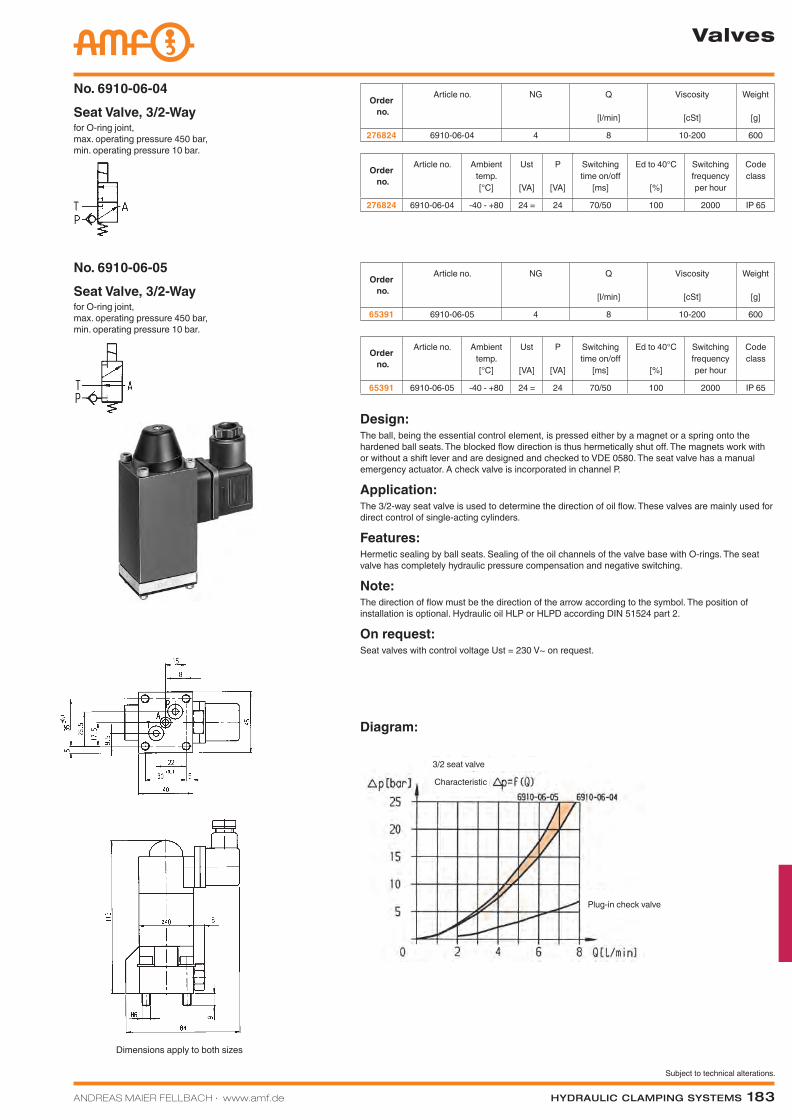
ANDREAS MAIER FELLBACH ∙ www.amf.de Hydraulic clamping SyStemS 183
Subject to technical alterations.
Valves
Dimensions apply to both sizes
Diagram:
for O-ring joint, max. operating pressure 450 bar, min. operating pressure 10 bar.
Seat Valve, 3/2-WayNo. 6910-06-04
Order no.
Article no. NG Q
[l/min]
Viscosity
[cSt]
Weight
[g]
276824 6910-06-04 4 8 10-200 600
Order no.
Article no. Ambient temp.[°C]
Ust
[VA]
P
[VA]
Switching time on/off
[ms]
Ed to 40°C
[%]
Switching frequency per hour
Code class
276824 6910-06-04 -40 - +80 24 = 24 70/50 100 2000 IP 65
for O-ring joint, max. operating pressure 450 bar, min. operating pressure 10 bar.
Seat Valve, 3/2-WayNo. 6910-06-05
Order no.
Article no. NG Q
[l/min]
Viscosity
[cSt]
Weight
[g]
65391 6910-06-05 4 8 10-200 600
Order no.
Article no. Ambient temp.[°C]
Ust
[VA]
P
[VA]
Switching time on/off
[ms]
Ed to 40°C
[%]
Switching frequency per hour
Code class
65391 6910-06-05 -40 - +80 24 = 24 70/50 100 2000 IP 65
Design:The ball, being the essential control element, is pressed either by a magnet or a spring onto the hardened ball seats. The blocked flow direction is thus hermetically shut off. The magnets work with or without a shift lever and are designed and checked to VDE 0580. The seat valve has a manual emergency actuator. A check valve is incorporated in channel P.
Application:The 3/2-way seat valve is used to determine the direction of oil flow. These valves are mainly used for direct control of single-acting cylinders.
Features:Hermetic sealing by ball seats. Sealing of the oil channels of the valve base with O-rings. The seat valve has completely hydraulic pressure compensation and negative switching.
Note:The direction of flow must be the direction of the arrow according to the symbol. The position of installation is optional. Hydraulic oil HLP or HLPD according DIN 51524 part 2.
On request:Seat valves with control voltage Ust = 230 V~ on request.
Plug-in check valve
3/2 seat valve
Characteristic
Katalog_2012_Hydraulik_EN_ohnePreise.indd 183 3/28/2013 8:38:39 AM
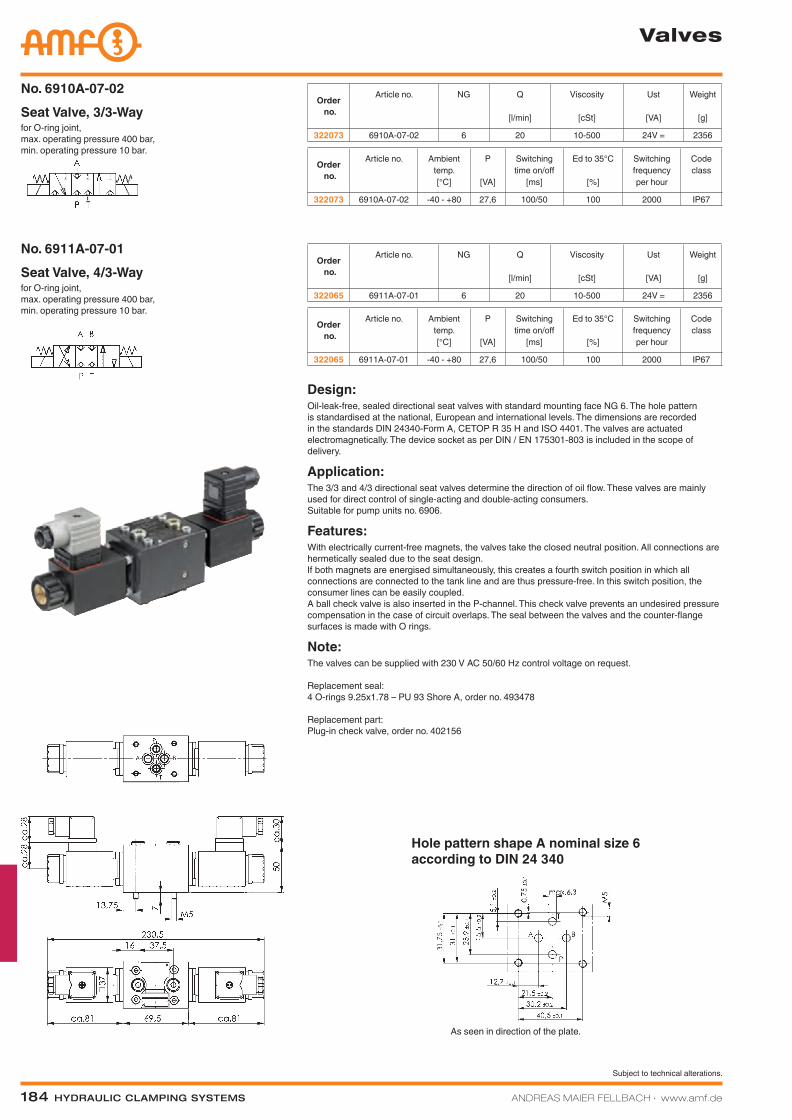
184 Hydraulic clamping SyStemS ANDREAS MAIER FELLBACH ∙ www.amf.de
Subject to technical alterations.
Valves
for O-ring joint, max. operating pressure 400 bar, min. operating pressure 10 bar.
Seat Valve, 3/3-WayNo. 6910A-07-02
Order no.
Article no. NG Q
[l/min]
Viscosity
[cSt]
Ust
[VA]
Weight
[g]
322073 6910A-07-02 6 20 10-500 24V = 2356
Order no.
Article no. NG Q
[l/min]
Viscosity
[cSt]
Ust
[VA]
Weight
[g]
322065 6911A-07-01 6 20 10-500 24V = 2356for O-ring joint, max. operating pressure 400 bar, min. operating pressure 10 bar.
Seat Valve, 4/3-WayNo. 6911A-07-01
Order no.
Article no. Ambient temp.[°C]
P
[VA]
Switching time on/off
[ms]
Ed to 35°C
[%]
Switching frequency per hour
Code class
322065 6911A-07-01 -40 - +80 27,6 100/50 100 2000 IP67
Order no.
Article no. Ambient temp.[°C]
P
[VA]
Switching time on/off
[ms]
Ed to 35°C
[%]
Switching frequency per hour
Code class
322073 6910A-07-02 -40 - +80 27,6 100/50 100 2000 IP67
Design:Oil-leak-free, sealed directional seat valves with standard mounting face NG 6. The hole pattern is standardised at the national, European and international levels. The dimensions are recorded in the standards DIN 24340-Form A, CETOP R 35 H and ISO 4401. The valves are actuated electromagnetically. The device socket as per DIN / EN 175301-803 is included in the scope of delivery.
Application:The 3/3 and 4/3 directional seat valves determine the direction of oil flow. These valves are mainly used for direct control of single-acting and double-acting consumers. Suitable for pump units no. 6906.
Features:With electrically current-free magnets, the valves take the closed neutral position. All connections are hermetically sealed due to the seat design. If both magnets are energised simultaneously, this creates a fourth switch position in which all connections are connected to the tank line and are thus pressure-free. In this switch position, the consumer lines can be easily coupled. A ball check valve is also inserted in the P-channel. This check valve prevents an undesired pressure compensation in the case of circuit overlaps. The seal between the valves and the counter-flange surfaces is made with O rings.
Note:The valves can be supplied with 230 V AC 50/60 Hz control voltage on request. Replacement seal: 4 O-rings 9.25x1.78 – PU 93 Shore A, order no. 493478 Replacement part: Plug-in check valve, order no. 402156
As seen in direction of the plate.
Hole pattern shape A nominal size 6 according to DIN 24 340
Katalog_2012_Hydraulik_EN_ohnePreise.indd 184 3/28/2013 8:38:45 AM
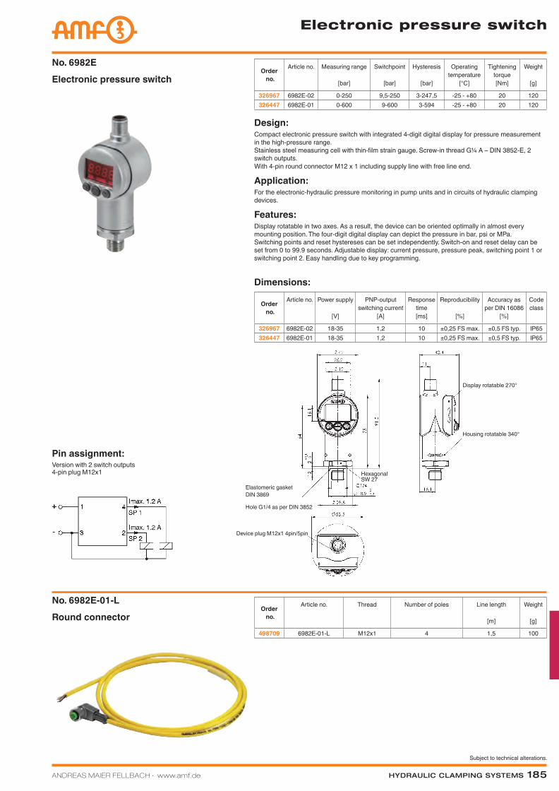
ANDREAS MAIER FELLBACH ∙ www.amf.de Hydraulic clamping SyStemS 185
Subject to technical alterations.
Electronic pressure switch
Pin assignment:Version with 2 switch outputs 4-pin plug M12x1
Electronic pressure switchNo. 6982E
Round connectorNo. 6982E-01-L
Order no.
Article no. Thread Number of poles Line length
[m]
Weight
[g]
498709 6982E-01-L M12x1 4 1,5 100
Order no.
Article no. Measuring range
[bar]
Switchpoint
[bar]
Hysteresis
[bar]
Operating temperature
[°C]
Tightening torque[Nm]
Weight
[g]
326967 6982E-02 0-250 9,5-250 3-247,5 -25 - +80 20 120326447 6982E-01 0-600 9-600 3-594 -25 - +80 20 120
Design:Compact electronic pressure switch with integrated 4-digit digital display for pressure measurement in the high-pressure range. Stainless steel measuring cell with thin-film strain gauge. Screw-in thread G¼ A – DIN 3852-E, 2 switch outputs. With 4-pin round connector M12 x 1 including supply line with free line end.
Application:For the electronic-hydraulic pressure monitoring in pump units and in circuits of hydraulic clamping devices.
Features:Display rotatable in two axes. As a result, the device can be oriented optimally in almost every mounting position. The four-digit digital display can depict the pressure in bar, psi or MPa. Switching points and reset hystereses can be set independently. Switch-on and reset delay can be set from 0 to 99.9 seconds. Adjustable display: current pressure, pressure peak, switching point 1 or switching point 2. Easy handling due to key programming.
Order no.
Article no. Power supply
[V]
PNP-output switching current
[A]
Response time[ms]
Reproducibility
[%]
Accuracy as per DIN 16086
[%]
Code class
326967 6982E-02 18-35 1,2 10 ±0,25 FS max. ±0,5 FS typ. IP65326447 6982E-01 18-35 1,2 10 ±0,25 FS max. ±0,5 FS typ. IP65
Dimensions:
Device plug M12x1 4pin/5pin
Hole G1/4 as per DIN 3852
Elastomeric gasketDIN 3869
Housing rotatable 340°
Display rotatable 270°
Hexagonal SW 27
Katalog_2012_Hydraulik_EN_ohnePreise.indd 185 3/28/2013 8:38:52 AM
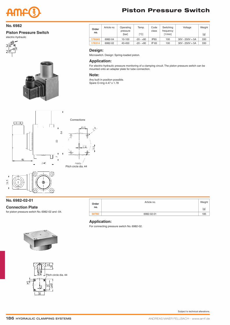
186 Hydraulic clamping SyStemS ANDREAS MAIER FELLBACH ∙ www.amf.de
Subject to technical alterations.
Piston Pressure Switch
electric-hydraulicPiston Pressure SwitchNo. 6982
Order no.
Article no. Operating pressure
[bar]
Temp.
[°C]
Code class
Switching frequency
[1/min]
Voltage Weight
[g]
176040 6982-04 10-100 -20 - +80 IP65 100 30V - 250V = 5A 330176214 6982-02 40-450 -20 - +80 IP 65 100 30V - 250V = 5A 330
Design:Microswitch. Design: Spring-loaded piston.
Application:For electric-hydraulic pressure monitoring of a clamping circuit. The piston pressure switch can be mounted onto an adapter plate for tube connection.
Note:Any built in position possible. Spare O-ring 4.47 x 1.78
for piston pressure switch No. 6982-02 and -04.Connection PlateNo. 6982-02-01
Order no.
Article no. Weight
[g]
60780 6982-02-01 185
Application:For connecting pressure switch No. 6982-02.
Pitch circle dia. 44
Pitch circle dia. 44
Connections
Katalog_2012_Hydraulik_EN_ohnePreise.indd 186 3/28/2013 8:38:55 AM
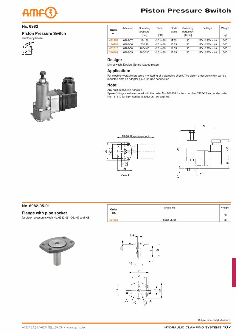
ANDREAS MAIER FELLBACH ∙ www.amf.de Hydraulic clamping SyStemS 187
Subject to technical alterations.
Piston Pressure Switch
electric-hydraulicPiston Pressure SwitchNo. 6982
Order no.
Article no. Operating pressure
[bar]
Temp.
[°C]
Code class
Switching frequency
[1/min]
Voltage Weight
[g]
492256 6982-07 12-170 -20 - +80 IP65 30 12V - 230V = 4A 300136291 6982-06 20-210 -20 - +80 IP 65 30 12V - 230V = 4A 300402610 6982-08 100-400 -20 - +80 IP 65 30 12V - 230V = 4A 300276881 6982-05 200-630 -20 - +80 IP 65 30 12V - 230V = 4A 300
Design:Microswitch. Design: Spring-loaded piston.
Application:For electric-hydraulic pressure monitoring of a clamping circuit. The piston pressure switch can be mounted onto an adapter plate for tube connection.
Note:Any built in position possible. Spare O-rings can be ordered with the order No. 161802 for item number 6982-05 and under order No. 161810 for item numbers 6982-06, -07 and -08.
Order no.
Article no. Weight
[g]
497636 6982-05-01 36for piston pressure switch No. 6982-05, -06, -07 and -08.Flange with pipe socketNo. 6982-05-01
View A
75-86 Plug-dependent
Katalog_2012_Hydraulik_EN_ohnePreise.indd 187 3/28/2013 8:38:57 AM
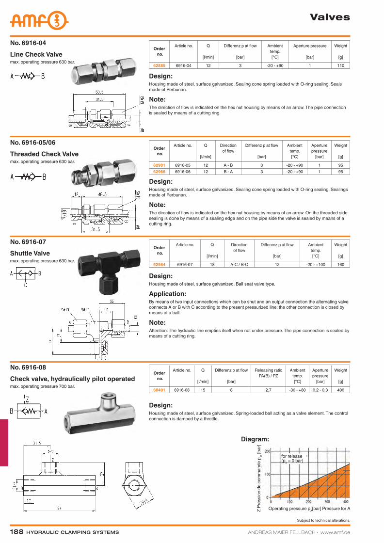
188 Hydraulic clamping SyStemS ANDREAS MAIER FELLBACH ∙ www.amf.de
Subject to technical alterations.
Valves
Diagram:
max. operating pressure 630 bar.Line Check ValveNo. 6916-04
Order no.
Article no. Q
[l/min]
Differenz p at flow
[bar]
Ambient temp.[°C]
Aperture pressure
[bar]
Weight
[g]
62885 6916-04 12 3 -20 - +90 1 110
Design:Housing made of steel, surface galvanized. Sealing cone spring loaded with O-ring sealing. Seals made of Perbunan.
Note:The direction of flow is indicated on the hex nut housing by means of an arrow. The pipe connection is sealed by means of a cutting ring.
max. operating pressure 630 bar.Threaded Check ValveNo. 6916-05/06
Order no.
Article no. Q
[l/min]
Direction of flow
Differenz p at flow
[bar]
Ambient temp.[°C]
Aperture pressure
[bar]
Weight
[g]
62901 6916-05 12 A - B 3 -20 - +90 1 9562968 6916-06 12 B - A 3 -20 - +90 1 95
Design:Housing made of steel, surface galvanized. Sealing cone spring loaded with O-ring sealing. Sealings made of Perbunan.
Note:The direction of flow is indicated on the hex nut housing by means of an arrow. On the threaded side sealing is done by means of a sealing edge and on the pipe side the valve is sealed by means of a cutting ring.
max. operating pressure 630 bar.Shuttle ValveNo. 6916-07
Order no.
Article no. Q
[l/min]
Direction of flow
Differenz p at flow
[bar]
Ambient temp.[°C]
Weight
[g]
62984 6916-07 18 A-C / B-C 12 -20 - +100 160
Design:Housing made of steel, surface galvanized. Ball seat valve type.
Application:By means of two input connections which can be shut and an output connection the alternating valve connects A or B with C according to the present pressurized line; the other connection is closed by means of a ball.
Note:Attention: The hydraulic line empties itself when not under pressure. The pipe connection is sealed by means of a cutting ring.
Design:Housing made of steel, surface galvanized. Spring-loaded ball acting as a valve element. The control connection is damped by a throttle.
Order no.
Article no. Q
[l/min]
Differenz p at flow
[bar]
Releasing ratio PA(B) / PZ
Ambient temp.[°C]
Aperture pressure
[bar]
Weight
[g]
60491 6916-08 15 8 2,7 -30 - +80 0,2 - 0,3 400max. operating pressure 700 bar.Check valve, hydraulically pilot operatedNo. 6916-08
for release (p8 = 0 bar)
Operating pressure pA[bar] Pressure for AZ Pr
essi
on d
e co
mm
ande
pSt
[bar
]
Katalog_2012_Hydraulik_EN_ohnePreise.indd 188 3/28/2013 8:39:00 AM
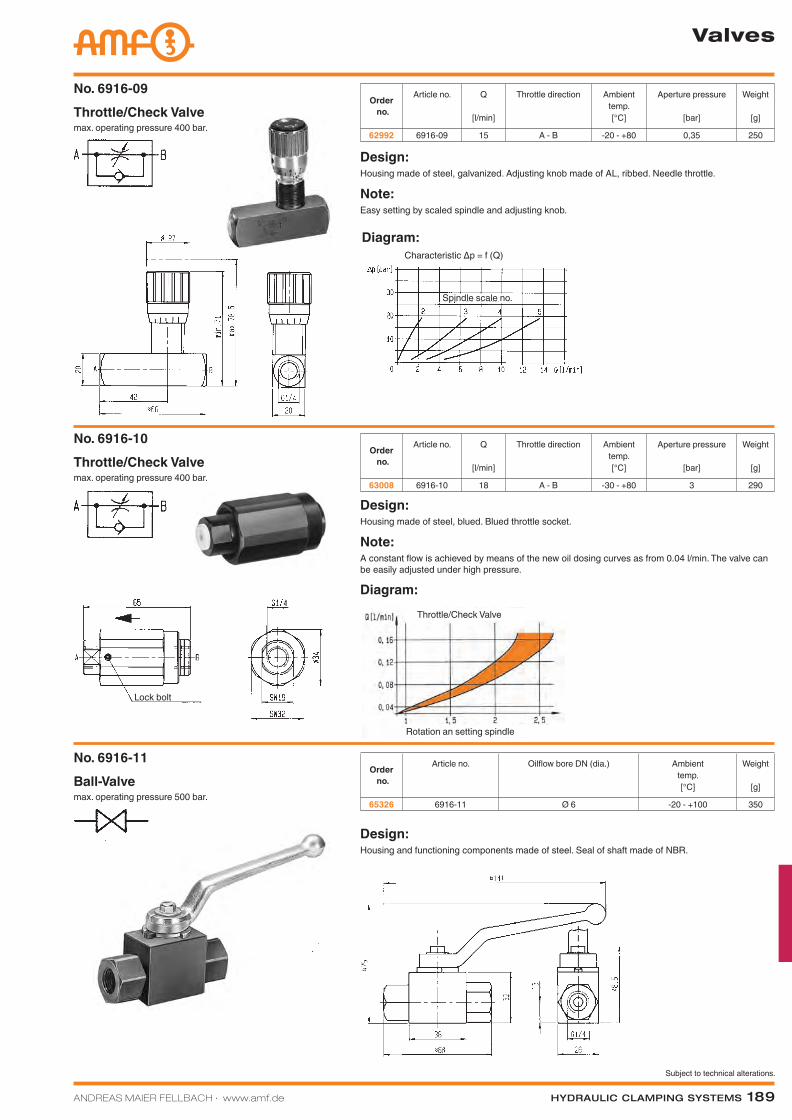
ANDREAS MAIER FELLBACH ∙ www.amf.de Hydraulic clamping SyStemS 189
Subject to technical alterations.
Diagram:
Valves
Diagram:
Diagram:Kennlinie Δp = f (Q)
max. operating pressure 400 bar.Throttle/Check ValveNo. 6916-09
Order no.
Article no. Q
[l/min]
Throttle direction Ambient temp.[°C]
Aperture pressure
[bar]
Weight
[g]
62992 6916-09 15 A - B -20 - +80 0,35 250
Design:Housing made of steel, galvanized. Adjusting knob made of AL, ribbed. Needle throttle.
Note:Easy setting by scaled spindle and adjusting knob.
max. operating pressure 400 bar.Throttle/Check ValveNo. 6916-10
Order no.
Article no. Q
[l/min]
Throttle direction Ambient temp.[°C]
Aperture pressure
[bar]
Weight
[g]
63008 6916-10 18 A - B -30 - +80 3 290
Design:Housing made of steel, blued. Blued throttle socket.
Note:A constant flow is achieved by means of the new oil dosing curves as from 0.04 l/min. The valve can be easily adjusted under high pressure.
Design:Housing and functioning components made of steel. Seal of shaft made of NBR.
Order no.
Article no. Oilflow bore DN (dia.) Ambient temp.[°C]
Weight
[g]
65326 6916-11 Ø 6 -20 - +100 350max. operating pressure 500 bar.Ball-ValveNo. 6916-11
Lock bolt
Throttle/Check Valve
Rotation an setting spindle
Characteristic Δp = f (Q)
Spindle scale no.
Katalog_2012_Hydraulik_EN_ohnePreise.indd 189 3/28/2013 8:39:02 AM
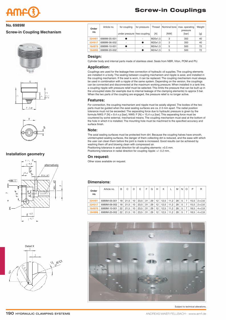
190 Hydraulic clamping SyStemS ANDREAS MAIER FELLBACH ∙ www.amf.de
Subject to technical alterations.
Screw-in Couplings
Screw-in Coupling MechanismNo. 6989M
Order no.
Article no. for coupling
under pressure
for pressure-
free coupling
Thread
[A]
Nominal bore
[NW]
max. operating pressure
[bar]
Weight
[g]
324491 6989M-05-001 ● - M20x1,5 3 350 40324517 6989M-06-002 - ● M20x1,5 3 350 40164970 6989M-10-001 ● - M24x1,5 5 500 72164996 6989M-20-002 - ● M24x1,5 5 500 72
Design:Cylinder body and internal parts made of stainless steel. Seals from NBR, Viton, POM and PU.
Application:Couplings are used for the leakage-free connection of hydraulic oil supplies. The coupling elements are installed in a body. The sealing between coupling mechanism and nipple is axial, and installed in the coupling mechanism. If the seal is worn, it can be replaced. The coupling mechanism must always be used in combination with a nipple of the same system. Depending on the version, the couplings can be connected and disconnected at the maximum working pressure. When installed in a tank line, a coupling nipple with pressure relief must be selected. This limits the pressure that can be built up in the uncoupled state (for example due to internal leakage of the clamping elements) to approx 5 bar. When the two parts of the coupling are engaged, the pressure relief is no longer active.
Features:For connection, the coupling mechanism and nipple must be axially aligned. The bodies of the two parts must be guided when the axial sealing surfaces are ca. 2-3 mm apart. The radial position tolerance must not be exceeded. The separating force due to hydraulic pressure is given by the formula NW3: F [N] = 9,4 x p [bar], NW5: F [N] = 15,4 x p [bar]. This separating force must be countered by some external, mechanical means. The coupling mechanism must seal at the bottom of the hole in which it is installed. The mounting hole must be machined to the specified accuracy and surface finish.
Note:The axial sealing surfaces must be protected from dirt. Because the coupling halves have smooth, uninterrupted sealing surfaces, the danger of them collecting dirt is reduced, and the ease with which the user can clean them before the joint is made is increased. Good results can be achieved by washing them off and blowing clean with compressed air. Positioning tolerance in axial direction for all coupling elements: +0.5 mm. Positioning tolerance in radial direction for coupling nipple: +/- 0.2 mm.
On request:Other sizes available on request.
Order no.
Article no. B C D E F G H K L M N O P R
324491 6989M-05-001 18 21,5 10 23,5 31 29 12 12,5 11,2 28 5 7 15,5 2 x 2,6324517 6989M-06-002 18 21,5 10 23,5 31 29 12 12,5 11,2 28 5 7 15,5 2 x 2,6164970 6989M-10-001 22 21,5 10 23,5 31 29 12 12,5 11,2 28 5 7 18,5 4 x 2,8164996 6989M-20-002 22 21,5 10 23,5 31 29 12 12,5 11,2 28 5 7 18,5 4 x 2,8
Dimensions:
Installation geometry
Detail X
alternatively
Katalog_2012_Hydraulik_EN_ohnePreise.indd 190 3/28/2013 8:39:04 AM
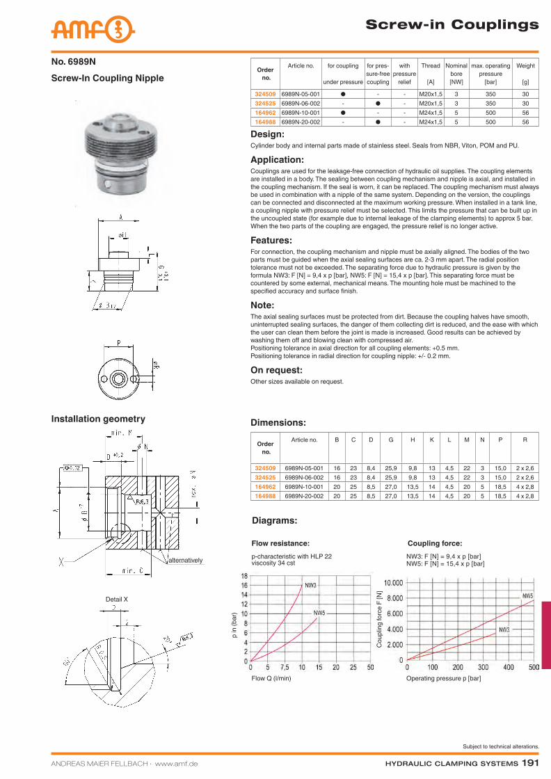
ANDREAS MAIER FELLBACH ∙ www.amf.de Hydraulic clamping SyStemS 191
Subject to technical alterations.
Screw-in Couplings
Diagrams:
NW3: F [N] = 9,4 x p [bar] NW5: F [N] = 15,4 x p [bar]
Screw-In Coupling NippleNo. 6989N
Order no.
Article no. for coupling
under pressure
for pres-sure-free coupling
with pressure
relief
Thread
[A]
Nominal bore[NW]
max. operating pressure
[bar]
Weight
[g]
324509 6989N-05-001 ● - - M20x1,5 3 350 30324525 6989N-06-002 - ● - M20x1,5 3 350 30164962 6989N-10-001 ● - - M24x1,5 5 500 56164988 6989N-20-002 - ● - M24x1,5 5 500 56
Design:Cylinder body and internal parts made of stainless steel. Seals from NBR, Viton, POM and PU.
Application:Couplings are used for the leakage-free connection of hydraulic oil supplies. The coupling elements are installed in a body. The sealing between coupling mechanism and nipple is axial, and installed in the coupling mechanism. If the seal is worn, it can be replaced. The coupling mechanism must always be used in combination with a nipple of the same system. Depending on the version, the couplings can be connected and disconnected at the maximum working pressure. When installed in a tank line, a coupling nipple with pressure relief must be selected. This limits the pressure that can be built up in the uncoupled state (for example due to internal leakage of the clamping elements) to approx 5 bar. When the two parts of the coupling are engaged, the pressure relief is no longer active.
Features:For connection, the coupling mechanism and nipple must be axially aligned. The bodies of the two parts must be guided when the axial sealing surfaces are ca. 2-3 mm apart. The radial position tolerance must not be exceeded. The separating force due to hydraulic pressure is given by the formula NW3: F [N] = 9,4 x p [bar], NW5: F [N] = 15,4 x p [bar]. This separating force must be countered by some external, mechanical means. The mounting hole must be machined to the specified accuracy and surface finish.
Note:The axial sealing surfaces must be protected from dirt. Because the coupling halves have smooth, uninterrupted sealing surfaces, the danger of them collecting dirt is reduced, and the ease with which the user can clean them before the joint is made is increased. Good results can be achieved by washing them off and blowing clean with compressed air. Positioning tolerance in axial direction for all coupling elements: +0.5 mm. Positioning tolerance in radial direction for coupling nipple: +/- 0.2 mm.
On request:Other sizes available on request.
Order no.
Article no. B C D G H K L M N P R
324509 6989N-05-001 16 23 8,4 25,9 9,8 13 4,5 22 3 15,0 2 x 2,6324525 6989N-06-002 16 23 8,4 25,9 9,8 13 4,5 22 3 15,0 2 x 2,6164962 6989N-10-001 20 25 8,5 27,0 13,5 14 4,5 20 5 18,5 4 x 2,8164988 6989N-20-002 20 25 8,5 27,0 13,5 14 4,5 20 5 18,5 4 x 2,8
Dimensions:Installation geometry
Detail X
alternatively
Operating pressure p [bar]
Cou
plin
g fo
rce
F [N
]
Flow Q (l/min)
p in
(bar
)
Coupling force:Flow resistance:p-characteristic with HLP 22 viscosity 34 cst
Katalog_2012_Hydraulik_EN_ohnePreise.indd 191 3/28/2013 8:39:06 AM
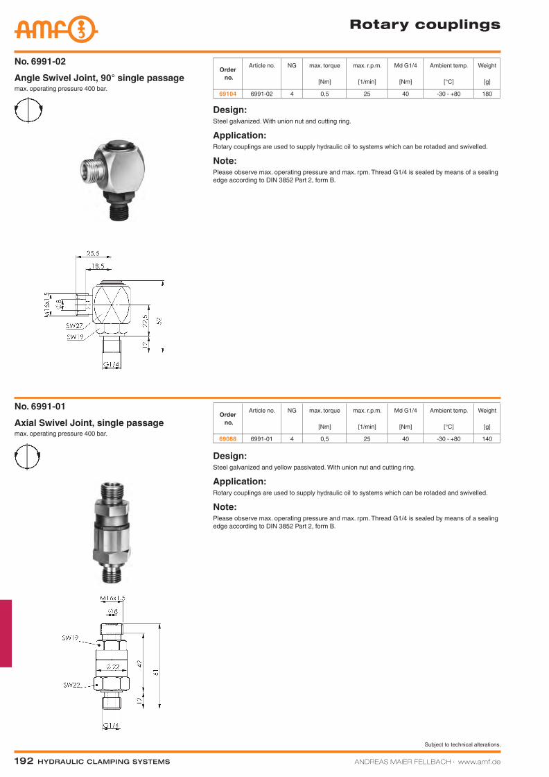
192 Hydraulic clamping SyStemS ANDREAS MAIER FELLBACH ∙ www.amf.de
Subject to technical alterations.
Rotary couplings
Order no.
Article no. NG max. torque
[Nm]
max. r.p.m.
[1/min]
Md G1/4
[Nm]
Ambient temp.
[°C]
Weight
[g]
69104 6991-02 4 0,5 25 40 -30 - +80 180max. operating pressure 400 bar.Angle Swivel Joint, 90° single passageNo. 6991-02
Design:Steel galvanized. With union nut and cutting ring.
Application:Rotary couplings are used to supply hydraulic oil to systems which can be rotaded and swivelled.
Note:Please observe max. operating pressure and max. rpm. Thread G1/4 is sealed by means of a sealing edge according to DIN 3852 Part 2, form B.
max. operating pressure 400 bar.Axial Swivel Joint, single passageNo. 6991-01
Design:Steel galvanized and yellow passivated. With union nut and cutting ring.
Application:Rotary couplings are used to supply hydraulic oil to systems which can be rotaded and swivelled.
Note:Please observe max. operating pressure and max. rpm. Thread G1/4 is sealed by means of a sealing edge according to DIN 3852 Part 2, form B.
Order no.
Article no. NG max. torque
[Nm]
max. r.p.m.
[1/min]
Md G1/4
[Nm]
Ambient temp.
[°C]
Weight
[g]
69088 6991-01 4 0,5 25 40 -30 - +80 140
Katalog_2012_Hydraulik_EN_ohnePreise.indd 192 3/28/2013 8:39:12 AM
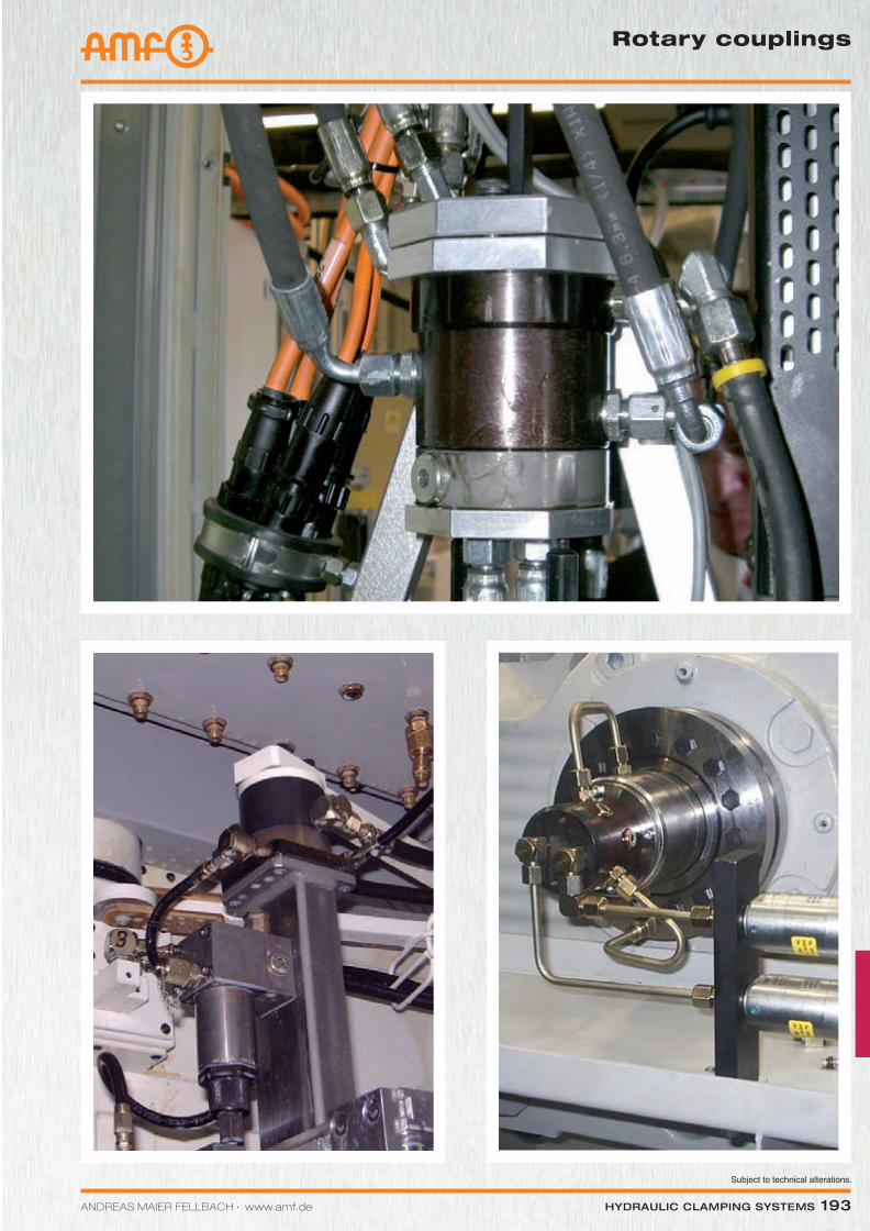
Subject to technical alterations.
ANDREAS MAIER FELLBACH ∙ www.amf.de Hydraulic clamping SyStemS 193
Rotary couplings
Katalog_2012_Hydraulik_EN_ohnePreise.indd 193 3/28/2013 8:39:16 AM
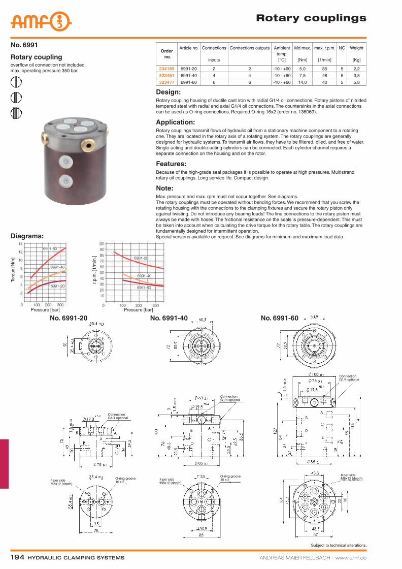
194 Hydraulic clamping SyStemS ANDREAS MAIER FELLBACH ∙ www.amf.de
Subject to technical alterations.
Rotary couplings
No. 6991-20 No. 6991-40 No. 6991-60
Order no.
Article no. Connections
inputs
Connections outputs Ambient temp.[°C]
Md max.
[Nm]
max. r.p.m.
[1/min]
NG Weight
[Kg]
334185 6991-20 2 2 -10 - +60 5,0 85 5 2,2323451 6991-40 4 4 -10 - +60 7,5 48 5 3,8323477 6991-60 6 6 -10 - +60 14,0 40 5 5,8
overflow oil connection not included, max. operating pressure 350 bar
Rotary couplingNo. 6991
Design:Rotary coupling housing of ductile cast iron with radial G1/4 oil connections. Rotary pistons of nitrided tempered steel with radial and axial G1/4 oil connections. The countersinks in the axial connections can be used as O-ring connections. Required O-ring 16x2 (order no. 136069).
Application:Rotary couplings transmit flows of hydraulic oil from a stationary machine component to a rotating one. They are located in the rotary axis of a rotating system. The rotary couplings are generally designed for hydraulic systems. To transmit air flows, they have to be filtered, oiled, and free of water. Single-acting and double-acting cylinders can be connected. Each cylinder channel requires a separate connection on the housing and on the rotor.
Features:Because of the high-grade seal packages it is possible to operate at high pressures. Multistrand rotary oil couplings. Long service life. Compact design.
Note:Max. pressure and max. rpm must not occur together. See diagrams. The rotary couplings must be operated without bending forces. We recommend that you screw the rotating housing with the connections to the clamping fixtures and secure the rotary piston only against twisting. Do not introduce any bearing loads! The line connections to the rotary piston must always be made with hoses. The frictional resistance on the seals is pressure-dependent. This must be taken into account when calculating the drive torque for the rotary table. The rotary couplings are fundamentally designed for intermittent operation. Special versions available on request. See diagrams for minimum and maximum load data.Diagrams:
Pressure [bar]
Torq
ue [N
m]
Pressure [bar]
r.p.m
. [1/
min
.]
Connection G1/4 optional
Connection G1/4 optional
Connection G1/4 optional
O-ring groove 16 x 2
O-ring groove 16 x 24 per side
M8x12 (depth)4 per side M8x12 (depth)
6 per side M8x12 (depth)
Katalog_2012_Hydraulik_EN_ohnePreise.indd 194 3/28/2013 8:39:21 AM
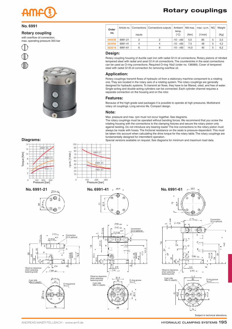
ANDREAS MAIER FELLBACH ∙ www.amf.de Hydraulic clamping SyStemS 195
Subject to technical alterations.
Rotary couplings
No. 6991-21 No. 6991-41 No. 6991-61
Design:Rotary coupling housing of ductile cast iron with radial G1/4 oil connections. Rotary pistons of nitrided tempered steel with radial and axial G1/4 oil connections. The countersinks in the axial connections can be used as O-ring connections. Required O-ring 16x2 (order no. 136069). Cover of tempered steel with radial G1/8 oil connection for removing overflow oil.
Application:Rotary couplings transmit flows of hydraulic oil from a stationary machine component to a rotating one. They are located in the rotary axis of a rotating system. The rotary couplings are generally designed for hydraulic systems. To transmit air flows, they have to be filtered, oiled, and free of water. Single-acting and double-acting cylinders can be connected. Each cylinder channel requires a separate connection on the housing and on the rotor.
Features:Because of the high-grade seal packages it is possible to operate at high pressures. Multistrand rotary oil couplings. Long service life. Compact design.
Note:Max. pressure and max. rpm must not occur together. See diagrams. The rotary couplings must be operated without bending forces. We recommend that you screw the rotating housing with the connections to the clamping fixtures and secure the rotary piston only against twisting. Do not introduce any bearing loads! The line connections to the rotary piston must always be made with hoses. The frictional resistance on the seals is pressure-dependent. This must be taken into account when calculating the drive torque for the rotary table. The rotary couplings are fundamentally designed for intermittent operation. Special versions available on request. See diagrams for minimum and maximum load data.
Order no.
Article no. Connections
inputs
Connections outputs Ambient temp.[°C]
Md max.
[Nm]
max. r.p.m.
[1/min]
NG Weight
[Kg]
445536 6991-21 2 2 -10 - +60 5,0 85 5 2,5323493 6991-41 4 4 -10 - +60 7,5 48 5 4,2323519 6991-61 6 6 -10 - +60 14,0 40 5 6,2
with overflow oil connection, max. operating pressure 350 bar
Rotary couplingNo. 6991
Diagrams:
Pressure [bar]
Torq
ue [N
m]
Pressure [bar]
r.p.m
. [1/
min
.]
Connection G1/4 optional
Connection G1/4 optional
Connection G1/4 optional
O-ring groove 16 x 2
O-ring groove 16 x 24 per side
M8x12 (depth) 4 per side M8x12 (depth)
6 per side M8x12 (depth)
O-ring groove 16 x 2
Observe clearance when selecting fastening bolts
Observe clearance when selecting fastening bolts
Observe clearance when selecting fastening bolts
Katalog_2012_Hydraulik_EN_ohnePreise.indd 195 3/28/2013 8:39:27 AM
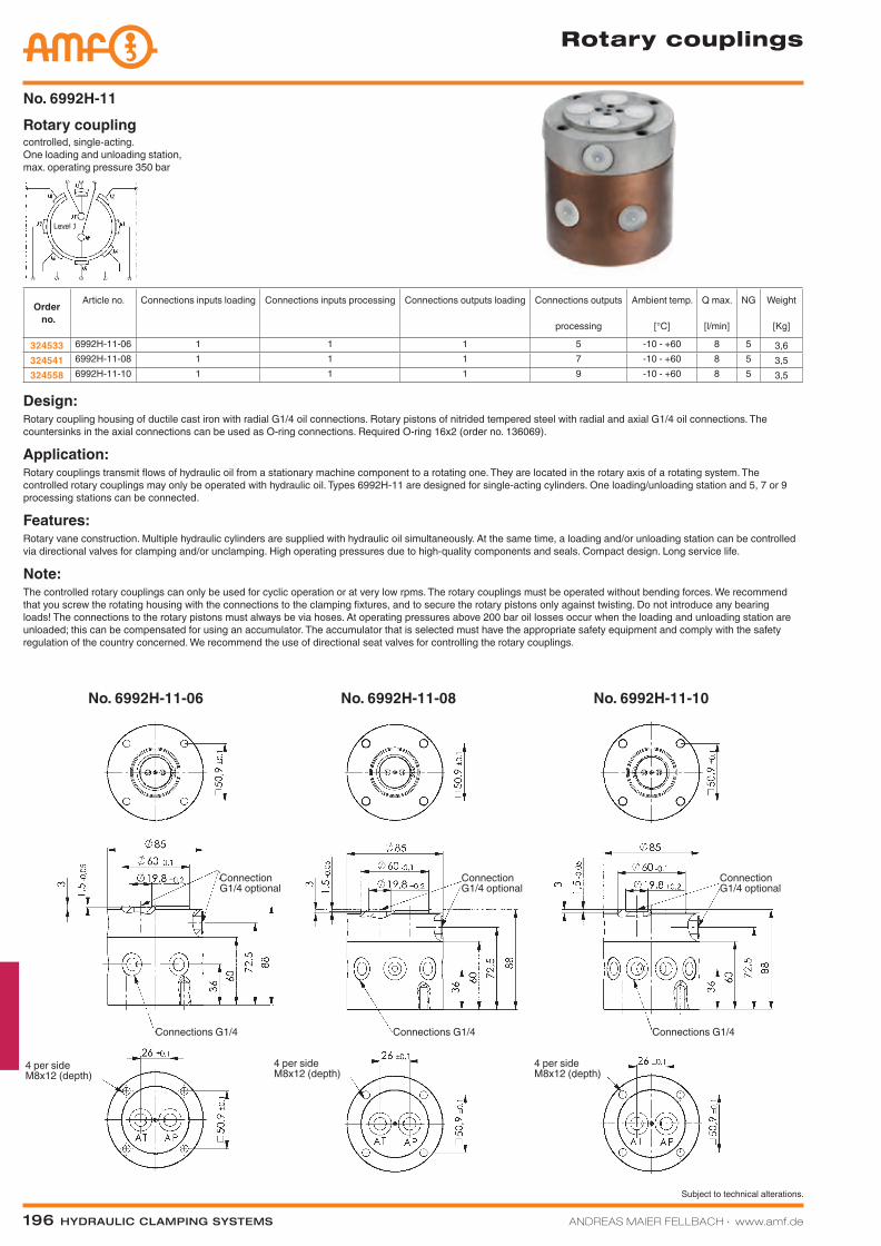
196 Hydraulic clamping SyStemS ANDREAS MAIER FELLBACH ∙ www.amf.de
Subject to technical alterations.
Rotary couplings
No. 6992H-11-06 No. 6992H-11-08 No. 6992H-11-10
controlled, single-acting. One loading and unloading station, max. operating pressure 350 bar
Rotary couplingNo. 6992H-11
Design:Rotary coupling housing of ductile cast iron with radial G1/4 oil connections. Rotary pistons of nitrided tempered steel with radial and axial G1/4 oil connections. The countersinks in the axial connections can be used as O-ring connections. Required O-ring 16x2 (order no. 136069).
Application:Rotary couplings transmit flows of hydraulic oil from a stationary machine component to a rotating one. They are located in the rotary axis of a rotating system. The controlled rotary couplings may only be operated with hydraulic oil. Types 6992H-11 are designed for single-acting cylinders. One loading/unloading station and 5, 7 or 9 processing stations can be connected.
Features:Rotary vane construction. Multiple hydraulic cylinders are supplied with hydraulic oil simultaneously. At the same time, a loading and/or unloading station can be controlled via directional valves for clamping and/or unclamping. High operating pressures due to high-quality components and seals. Compact design. Long service life.
Note:The controlled rotary couplings can only be used for cyclic operation or at very low rpms. The rotary couplings must be operated without bending forces. We recommend that you screw the rotating housing with the connections to the clamping fixtures, and to secure the rotary pistons only against twisting. Do not introduce any bearing loads! The connections to the rotary pistons must always be via hoses. At operating pressures above 200 bar oil losses occur when the loading and unloading station are unloaded; this can be compensated for using an accumulator. The accumulator that is selected must have the appropriate safety equipment and comply with the safety regulation of the country concerned. We recommend the use of directional seat valves for controlling the rotary couplings.
Order no.
Article no. Connections inputs loading Connections inputs processing Connections outputs loading Connections outputs
processing
Ambient temp.
[°C]
Q max.
[l/min]
NG Weight
[Kg]
324533 6992H-11-06 1 1 1 5 -10 - +60 8 5 3,6324541 6992H-11-08 1 1 1 7 -10 - +60 8 5 3,5324558 6992H-11-10 1 1 1 9 -10 - +60 8 5 3,5
Connection G1/4 optional
4 per side M8x12 (depth)
Connections G1/4 Connections G1/4 Connections G1/4
Connection G1/4 optional
Connection G1/4 optional
4 per side M8x12 (depth)
4 per side M8x12 (depth)
Level 1
Katalog_2012_Hydraulik_EN_ohnePreise.indd 196 3/28/2013 8:39:30 AM
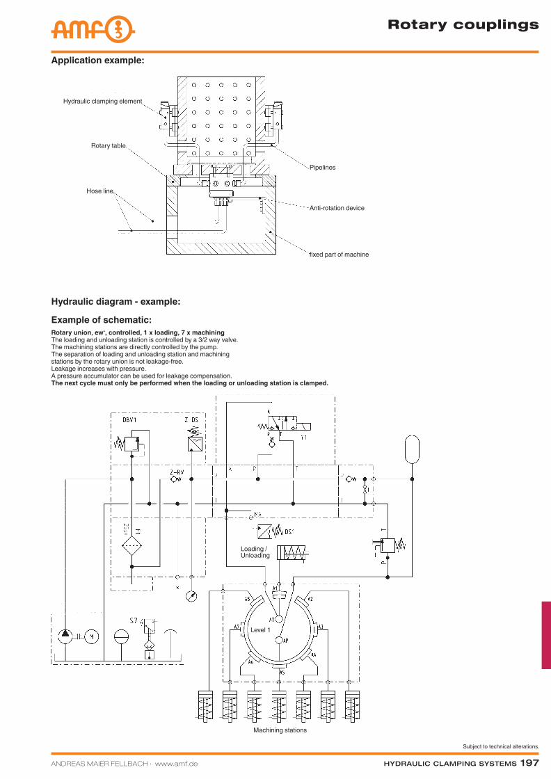
ANDREAS MAIER FELLBACH ∙ www.amf.de Hydraulic clamping SyStemS 197
Subject to technical alterations.
Application example:
Rotary couplings
Hydraulic clamping element
Rotary table
Hose line
Pipelines
Anti-rotation device
fixed part of machine
Hydraulic diagram - example:
Example of schematic:Rotary union‚ ew‘, controlled, 1 x loading, 7 x machiningThe loading and unloading station is controlled by a 3/2 way valve. The machining stations are directly controlled by the pump. The separation of loading and unloading station and machining stations by the rotary union is not leakage-free. Leakage increases with pressure. A pressure accumulator can be used for leakage compensation. The next cycle must only be performed when the loading or unloading station is clamped.
Machining stations
Loading / Unloading
Level 1
Katalog_2012_Hydraulik_EN_ohnePreise.indd 197 3/28/2013 8:39:31 AM
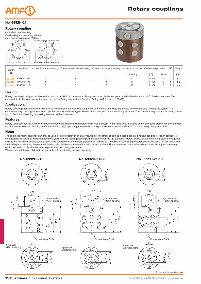
198 Hydraulic clamping SyStemS ANDREAS MAIER FELLBACH ∙ www.amf.de
Subject to technical alterations.
Rotary couplings
No. 6992H-21-06 No. 6992H-21-08 No. 6992H-21-10
controlled, double-acting. One loading and unloading station, max. operating pressure 350 bar
Rotary couplingNo. 6992H-21
Design:Rotary coupling housing of ductile cast iron with radial G1/4 oil connections. Rotary pistons of nitrided tempered steel with radial and axial G1/4 oil connections. The countersinks in the axial connections can be used as O-ring connections. Required O-ring 16x2 (order no. 136069).
Application:Rotary couplings transmit flows of hydraulic oil from a stationary machine component to a rotating one. They are located in the rotary axis of a rotating system. The controlled rotary couplings may only be operated with hydraulic oil. Types 6992H-21 are designed for double-acting cylinders. One double-acting loading/unloading station and 5, 7 or 9 double-acting processing stations can be connected.
Features:Rotary vane construction. Multiple hydraulic cylinders are supplied with hydraulic oil simultaneously. At the same time, a loading and/or unloading station can be controlled via directional valves for clamping and/or unclamping. High operating pressures due to high-quality components and seals. Compact design. Long service life.
Note:The controlled rotary couplings can only be used for cyclic operation or at very low rpms. The rotary couplings must be operated without bending forces. In contrast to the uncontrolled versions, we recommend that you screw the rotating housing with the connections to the clamping fixtures, and to secure the rotary pistons only against twisting. Do not introduce any bearing loads! The connections to the rotary pistons must always be via hoses. At operating pressures above 200 bar oil losses occur when the loading and unloading station are unloaded; this can be compensated for using an accumulator. The accumulator that is selected must have the appropriate safety equipment and comply with the safety regulation of the country concerned. We recommend the use of directional seat valves for controlling the rotary couplings.
Order no.
Article no. Connections inputs loading Connections inputs processing Connections outputs loading Connections outputs
processing
Ambient temp.
[°C]
Q max.
[l/min]
NG Weight
[Kg]
324566 6992H-21-06 2 2 2 10 -10 - +60 8 5 4,1324574 6992H-21-08 2 2 2 14 -10 - +60 8 5 4,0324582 6992H-21-10 2 2 2 18 -10 - +60 8 5 3,9
Connection G1/4 optional
4 per side M8x12 (depth)
Connections G1/4 Connections G1/4 Connections G1/4
Connection G1/4 optional
Connection G1/4 optional
4 per side M8x12 (depth)
4 per side M8x12 (depth)
Level 1 Level 2
Katalog_2012_Hydraulik_EN_ohnePreise.indd 198 3/28/2013 8:39:35 AM
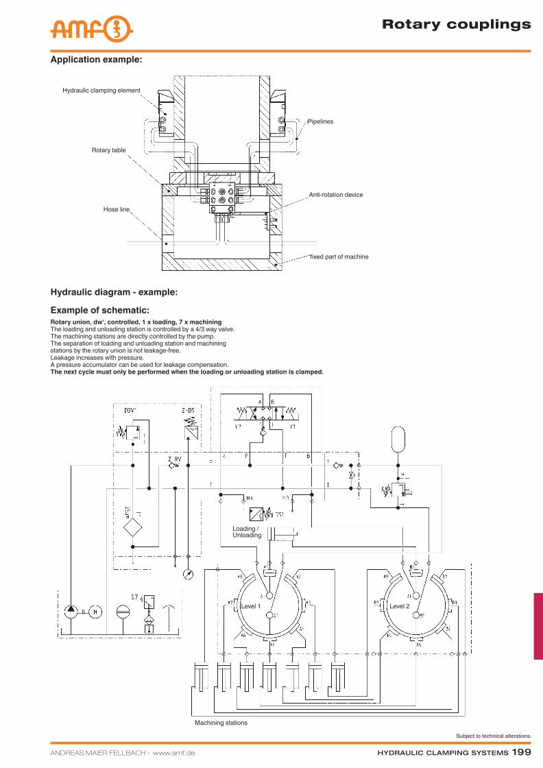
ANDREAS MAIER FELLBACH ∙ www.amf.de Hydraulic clamping SyStemS 199
Subject to technical alterations.
Rotary couplings
Application example:
Hydraulic clamping element
Rotary table
Hose line
Pipelines
Anti-rotation device
fixed part of machine
Machining stations
Loading / Unloading
Level 1
Hydraulic diagram - example:
Example of schematic:Rotary union‚ dw‘, controlled, 1 x loading, 7 x machiningThe loading and unloading station is controlled by a 4/3 way valve. The machining stations are directly controlled by the pump. The separation of loading and unloading station and machining stations by the rotary union is not leakage-free. Leakage increases with pressure. A pressure accumulator can be used for leakage compensation. The next cycle must only be performed when the loading or unloading station is clamped.
Level 2
Katalog_2012_Hydraulik_EN_ohnePreise.indd 199 3/28/2013 8:39:36 AM
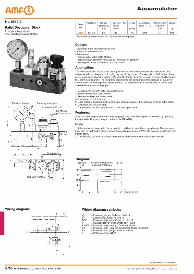
200 Hydraulic clamping SyStemS ANDREAS MAIER FELLBACH ∙ www.amf.de
Subject to technical alterations.
Diagram:
Accumulator
for single acting cylinders, max. operating pressure 400 bar.
Pallet Decoupler BlockNo. 6919-2
Design:- Distributor made of phosphatized steel - 3/2-way manual seat valve - Accumulator - Pressure-relief valve set to 400 bar - Pressure gauge (600 bar; nom. size 63; with glycerin damping) - Coupling connector No. 6990 G1/4 S and fittings
Application:The main application for the pallet decoupler block is to maintain pressure at fixtures which are disconnected from the pump unit during the machining process. For example on flexible machining centers with pallet changing systems. With tight hydraulic elements a loss in pressure shall be limited to 2 bar/h (see diagram). The integrated accumulator can compensate for a leakage-oil quantity of approx. 6 cm3 in the range from 150 to 400 bar. The pressure input is connected to P1 or P2 and abserved by the pressure gauge.
1. Couple pump unit with pallet decoupler block. 2. Switch manual seat valve to flow. 3. Remove workpiece or insert a new. 4. Operate pump unit (clamp). 5. Once pressure has been built up (check at pressure gauge), the seat valve must be set to close. 6. Operate pump unit (unclamp). 7. The pump unit is uncoupled from the pallet decoupler block.
Features:After disconnecting the pump unit the clamping fixture cannot be depressurized even by operating the seat valve. Compact design. Load outputs (K1 to K4).
Note:1. If the seat valve is opened in the uncoupled condition, it cannot be coupled again. The seat valve must then be switched to close. Loosen the coupling connector SW (AF) to depressurize 22 and then tighten again. 2. The clamping point can also have pressure applied when the seat valve is set to close.
* Adjustable between 20 and 250 bar at works (on request).
Wiring diagram:
Pressure gauges Pressure relief valveAccumulator 13 cm³
3/2 Manual directional valve
Flow position
Coupling nipple
Wiring diagram symbols: = Pressure gauges, Order no. 161414 SP = Accumulator, Order no. 67645 DBV = Pressure relief valve, Order no. 181222 V = Manual seat valve 3/2, Order no. 114298 K1–K4 = Pressure outputs (plug), Order no. 69419 P1 = Pressure input (coupling connector), Order no. 69039 P2 = Pressure input (plug), Order no. 69419 T = Release opening DBV
X ’
Pressure [bar]
Pressure-hold periods at various pressures
Clamping time
p=f (t)
Order no.
Article no. Set gas preload p0
[bar]
Reservoir volume[cm³]
NG Q max.
[l/min]
Connections inputs P1+P2
Connections outputs K1
to K4
Weight
[g]
61168 6919-2 80* 13 4 7,5 G1/4 G1/4 4400
Katalog_2012_Hydraulik_EN_ohnePreise.indd 200 3/28/2013 8:39:37 AM
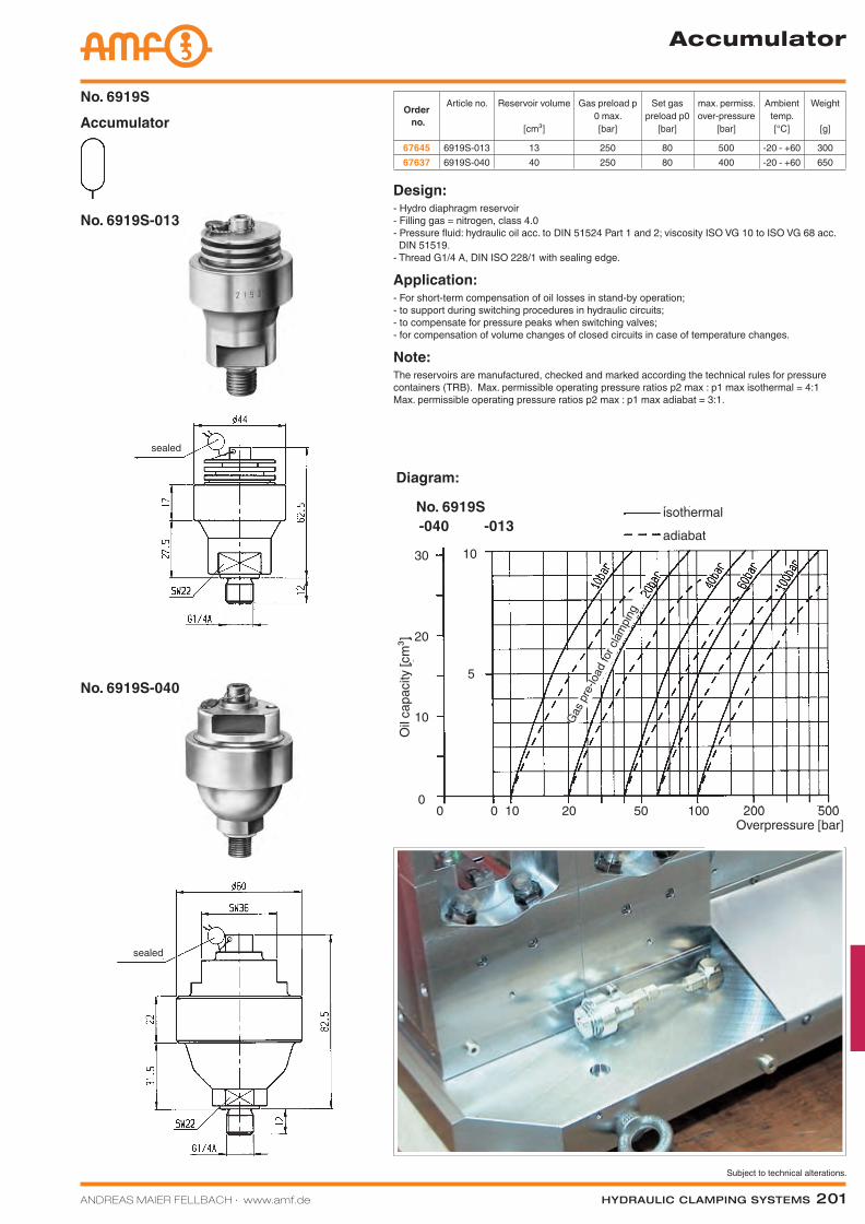
ANDREAS MAIER FELLBACH ∙ www.amf.de Hydraulic clamping SyStemS 201
Subject to technical alterations.
isotherm
adiabat
0 0 10 20 50 100 200 500Überdruck [bar]
10
0
20
30
Ölvo
lum
en [c
m³]
10
5
-040 -013No. 6919S
Diagram:
No. 6919S-013
No. 6919S-040
Accumulator
AccumulatorNo. 6919S
Order no.
Article no. Reservoir volume
[cm³]
Gas preload p 0 max.[bar]
Set gas preload p0
[bar]
max. permiss. over-pressure
[bar]
Ambient temp.[°C]
Weight
[g]
67645 6919S-013 13 250 80 500 -20 - +60 30067637 6919S-040 40 250 80 400 -20 - +60 650
Design:- Hydro diaphragm reservoir - Filling gas = nitrogen, class 4.0 - Pressure fluid: hydraulic oil acc. to DIN 51524 Part 1 and 2; viscosity ISO VG 10 to ISO VG 68 acc. DIN 51519. - Thread G1/4 A, DIN ISO 228/1 with sealing edge.
Application:- For short-term compensation of oil losses in stand-by operation; - to support during switching procedures in hydraulic circuits; - to compensate for pressure peaks when switching valves; - for compensation of volume changes of closed circuits in case of temperature changes.
Note:The reservoirs are manufactured, checked and marked according the technical rules for pressure containers (TRB). Max. permissible operating pressure ratios p2 max : p1 max isothermal = 4:1 Max. permissible operating pressure ratios p2 max : p1 max adiabat = 3:1.
sealed
isothermaladiabat
Overpressure [bar]
Oil c
apac
ity [c
m³]
sealed
Gas p
re-lo
ad fo
r clam
ping
Katalog_2012_Hydraulik_EN_ohnePreise.indd 201 3/28/2013 8:39:39 AM
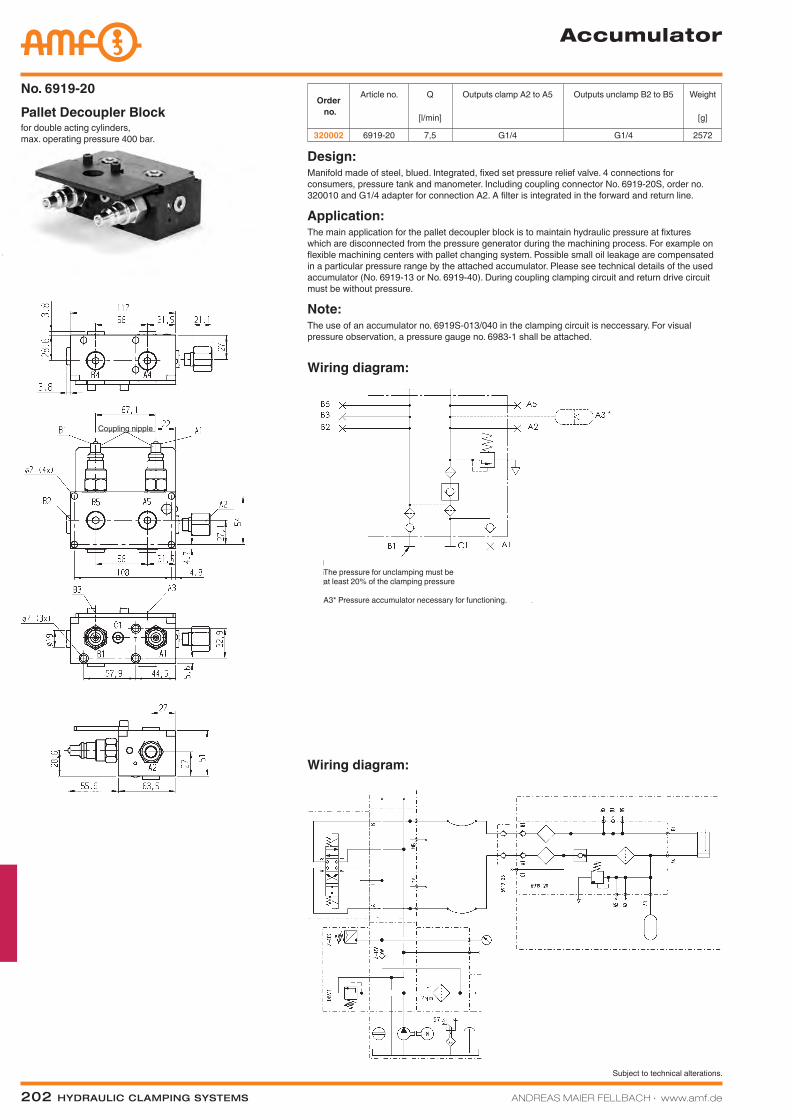
202 Hydraulic clamping SyStemS ANDREAS MAIER FELLBACH ∙ www.amf.de
Subject to technical alterations.
Accumulator
for double acting cylinders, max. operating pressure 400 bar.
Pallet Decoupler BlockNo. 6919-20
Order no.
Article no. Q
[l/min]
Outputs clamp A2 to A5 Outputs unclamp B2 to B5 Weight
[g]
320002 6919-20 7,5 G1/4 G1/4 2572
Design:Manifold made of steel, blued. Integrated, fixed set pressure relief valve. 4 connections for consumers, pressure tank and manometer. Including coupling connector No. 6919-20S, order no. 320010 and G1/4 adapter for connection A2. A filter is integrated in the forward and return line.
Application:The main application for the pallet decoupler block is to maintain hydraulic pressure at fixtures which are disconnected from the pressure generator during the machining process. For example on flexible machining centers with pallet changing system. Possible small oil leakage are compensated in a particular pressure range by the attached accumulator. Please see technical details of the used accumulator (No. 6919-13 or No. 6919-40). During coupling clamping circuit and return drive circuit must be without pressure.
Note:The use of an accumulator no. 6919S-013/040 in the clamping circuit is neccessary. For visual pressure observation, a pressure gauge no. 6983-1 shall be attached.
Wiring diagram:
Wiring diagram:
The pressure for unclamping must be at least 20% of the clamping pressure
A3* Pressure accumulator necessary for functioning.
Coupling nipple
Katalog_2012_Hydraulik_EN_ohnePreise.indd 202 3/28/2013 8:39:45 AM
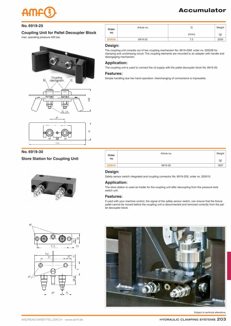
ANDREAS MAIER FELLBACH ∙ www.amf.de Hydraulic clamping SyStemS 203
Subject to technical alterations.
Accumulator
Design:The coupling unit consists out of two coupling mechanism No. 6919-25M, order no. 320036 for clamping and unclamping circuit. The coupling elements are mounted to an adapter with handle and disengaging mechanism.
Application:The coupling unit is used to connect the oil supply with the pallet decoupler block No. 6919-20.
Features:Simple handling due two hand operation. Interchanging of connections is impossible.
Order no.
Article no. Q
[l/min]
Weight
[g]
320028 6919-25 7,5 2200max. operating pressure 400 bar.Coupling Unit for Pallet Decoupler BlockNo. 6919-25
Store Station for Coupling UnitNo. 6919-30
Order no.
Article no. Weight
[g]
320044 6919-30 1837
Design:Safety sensor switch integrated and coupling connector No. 6919-20S, order no. 320010.
Application:The store station is used as holder for the coupling unit after decoupling from the pressure tank switch unit.
Features:If used with your machine control, the signal of the safety sensor switch, can ensure that the fixture pallet cannot be moved before the coupling unit is disconnected and removed correctly from the pal-let decoupler block.
Coupling mechanism
Katalog_2012_Hydraulik_EN_ohnePreise.indd 203 3/28/2013 8:39:48 AM
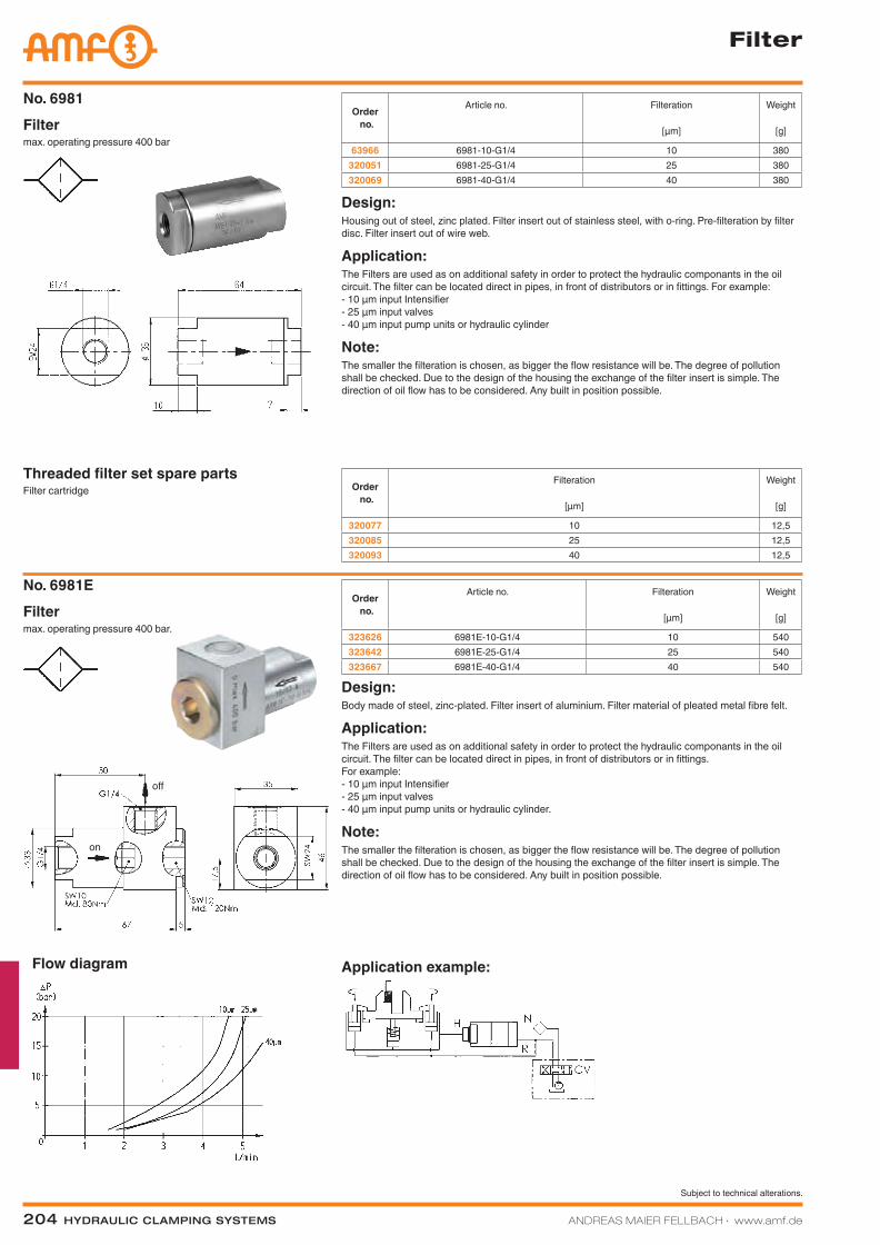
204 Hydraulic clamping SyStemS ANDREAS MAIER FELLBACH ∙ www.amf.de
Subject to technical alterations.
Application example:
Filter
Order no.
Article no. Filteration
[µm]
Weight
[g]
63966 6981-10-G1/4 10 380320051 6981-25-G1/4 25 380320069 6981-40-G1/4 40 380
Order no.
Article no. Filteration
[µm]
Weight
[g]
323626 6981E-10-G1/4 10 540323642 6981E-25-G1/4 25 540323667 6981E-40-G1/4 40 540
max. operating pressure 400 bar.FilterNo. 6981E
Design:Body made of steel, zinc-plated. Filter insert of aluminium. Filter material of pleated metal fibre felt.
Application:The Filters are used as on additional safety in order to protect the hydraulic componants in the oil circuit. The filter can be located direct in pipes, in front of distributors or in fittings. For example: - 10 µm input Intensifier - 25 µm input valves - 40 µm input pump units or hydraulic cylinder.
Note:The smaller the filteration is chosen, as bigger the flow resistance will be. The degree of pollution shall be checked. Due to the design of the housing the exchange of the filter insert is simple. The direction of oil flow has to be considered. Any built in position possible.
max. operating pressure 400 barFilterNo. 6981
Design:Housing out of steel, zinc plated. Filter insert out of stainless steel, with o-ring. Pre-filteration by filter disc. Filter insert out of wire web.
Application:The Filters are used as on additional safety in order to protect the hydraulic componants in the oil circuit. The filter can be located direct in pipes, in front of distributors or in fittings. For example: - 10 µm input Intensifier - 25 µm input valves - 40 µm input pump units or hydraulic cylinder
Note:The smaller the filteration is chosen, as bigger the flow resistance will be. The degree of pollution shall be checked. Due to the design of the housing the exchange of the filter insert is simple. The direction of oil flow has to be considered. Any built in position possible.
Order no.
Filteration
[µm]
Weight
[g]
320077 10 12,5320085 25 12,5320093 40 12,5
Filter cartridgeThreaded filter set spare parts
Flow diagram
off
on
Katalog_2012_Hydraulik_EN_ohnePreise.indd 204 3/28/2013 8:39:54 AM
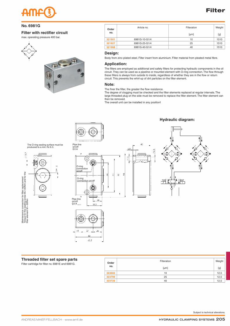
ANDREAS MAIER FELLBACH ∙ www.amf.de Hydraulic clamping SyStemS 205
Subject to technical alterations.
Filter
max. operating pressure 400 bar.Filter with rectifier circuitNo. 6981G
Order no.
Article no. Filteration
[µm]
Weight
[g]
321901 6981G-10-G1/4 10 1510321927 6981G-25-G1/4 25 1510321968 6981G-40-G1/4 40 1510
Design:Body from zinc-plated steel. Filter insert from aluminium. Filter material from pleated metal fibre.
Application:The filters are employed as additional and safety filters for protecting hydraulic components in the oil circuit. They can be used as a pipeline or mounted element with O-ring connection. The flow through these filters is always from outside to inside, regardless of whether they are in the flow or return circuit. This prevents the whirl-up of dirt particles on the filter element.
Note:The finer the filter, the greater the flow resistance. The degree of clogging must be checked and the filter elements replaced at regular intervals. The large threaded plug on the side must be removed to replace the filter element. The filter element can then be removed. The overall unit can be installed in any position!
Filter cartridge for filter no. 6981E and 6981G. Threaded filter set spare parts
Order no.
Filteration
[µm]
Weight
[g]
323683 10 12,5323709 25 12,5323725 40 12,5
Pipe lineon/offG1/4
Pipe lineon/offG1/4
O-ring connection on/off
O-ring connection on/off
The O-ring sealing surface must be produced to a min. Rz 6.3.
Mai
nten
ance
con
nect
ion
for fi
lter r
epla
cem
ent
Torq
ue fo
r the
sea
ling
scre
w M
=120
Nm
and
for t
he
filter
ele
men
t M =
80N
m
Hydraulic diagram:
Katalog_2012_Hydraulik_EN_ohnePreise.indd 205 3/28/2013 8:39:56 AM
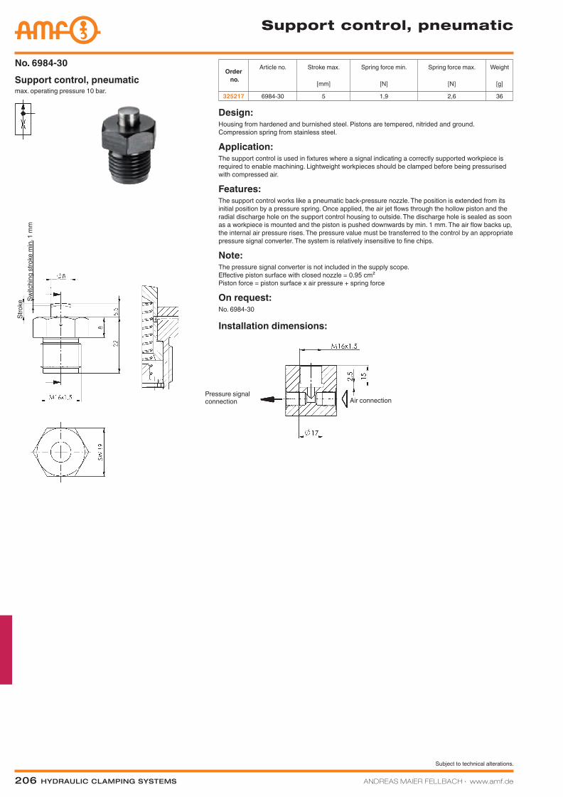
206 Hydraulic clamping SyStemS ANDREAS MAIER FELLBACH ∙ www.amf.de
Subject to technical alterations.
Installation dimensions:
max. operating pressure 10 bar.Support control, pneumaticNo. 6984-30
Support control, pneumatic
Order no.
Article no. Stroke max.
[mm]
Spring force min.
[N]
Spring force max.
[N]
Weight
[g]
325217 6984-30 5 1,9 2,6 36
Design:Housing from hardened and burnished steel. Pistons are tempered, nitrided and ground. Compression spring from stainless steel.
Application:The support control is used in fixtures where a signal indicating a correctly supported workpiece is required to enable machining. Lightweight workpieces should be clamped before being pressurised with compressed air.
Features:The support control works like a pneumatic back-pressure nozzle. The position is extended from its initial position by a pressure spring. Once applied, the air jet flows through the hollow piston and the radial discharge hole on the support control housing to outside. The discharge hole is sealed as soon as a workpiece is mounted and the piston is pushed downwards by min. 1 mm. The air flow backs up, the internal air pressure rises. The pressure value must be transferred to the control by an appropriate pressure signal converter. The system is relatively insensitive to fine chips.
Note:The pressure signal converter is not included in the supply scope. Effective piston surface with closed nozzle = 0.95 cm² Piston force = piston surface x air pressure + spring force
On request:No. 6984-30
Pressure signal connection Air connection
Switc
hing
stro
ke m
in. 1
mm
Stro
ke
Katalog_2012_Hydraulik_EN_ohnePreise.indd 206 3/28/2013 8:39:57 AM
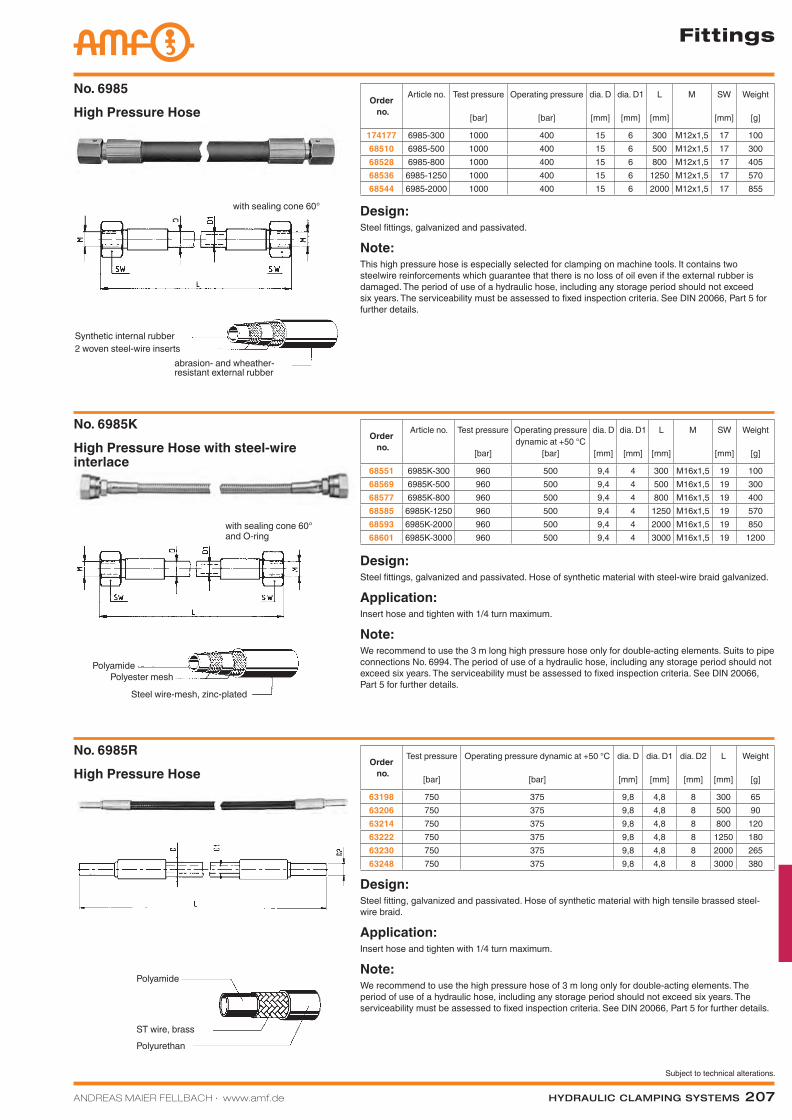
ANDREAS MAIER FELLBACH ∙ www.amf.de Hydraulic clamping SyStemS 207
Subject to technical alterations.
Fittings
Order no.
Article no. Test pressure
[bar]
Operating pressure
[bar]
dia. D
[mm]
dia. D1
[mm]
L
[mm]
M SW
[mm]
Weight
[g]
174177 6985-300 1000 400 15 6 300 M12x1,5 17 10068510 6985-500 1000 400 15 6 500 M12x1,5 17 30068528 6985-800 1000 400 15 6 800 M12x1,5 17 40568536 6985-1250 1000 400 15 6 1250 M12x1,5 17 57068544 6985-2000 1000 400 15 6 2000 M12x1,5 17 855
High Pressure HoseNo. 6985
Design:Steel fittings, galvanized and passivated.
Note:This high pressure hose is especially selected for clamping on machine tools. It contains two steelwire reinforcements which guarantee that there is no loss of oil even if the external rubber is damaged. The period of use of a hydraulic hose, including any storage period should not exceed six years. The serviceability must be assessed to fixed inspection criteria. See DIN 20066, Part 5 for further details.
Design:Steel fittings, galvanized and passivated. Hose of synthetic material with steel-wire braid galvanized.
Application:Insert hose and tighten with 1/4 turn maximum.
Note:We recommend to use the 3 m long high pressure hose only for double-acting elements. Suits to pipe connections No. 6994. The period of use of a hydraulic hose, including any storage period should not exceed six years. The serviceability must be assessed to fixed inspection criteria. See DIN 20066, Part 5 for further details.
Order no.
Article no. Test pressure
[bar]
Operating pressure dynamic at +50 °C
[bar]
dia. D
[mm]
dia. D1
[mm]
L
[mm]
M SW
[mm]
Weight
[g]
68551 6985K-300 960 500 9,4 4 300 M16x1,5 19 10068569 6985K-500 960 500 9,4 4 500 M16x1,5 19 30068577 6985K-800 960 500 9,4 4 800 M16x1,5 19 40068585 6985K-1250 960 500 9,4 4 1250 M16x1,5 19 57068593 6985K-2000 960 500 9,4 4 2000 M16x1,5 19 85068601 6985K-3000 960 500 9,4 4 3000 M16x1,5 19 1200
High Pressure Hose with steel-wire interlace
No. 6985K
High Pressure HoseNo. 6985R
Order no.
Test pressure
[bar]
Operating pressure dynamic at +50 °C
[bar]
dia. D
[mm]
dia. D1
[mm]
dia. D2
[mm]
L
[mm]
Weight
[g]
63198 750 375 9,8 4,8 8 300 6563206 750 375 9,8 4,8 8 500 9063214 750 375 9,8 4,8 8 800 12063222 750 375 9,8 4,8 8 1250 18063230 750 375 9,8 4,8 8 2000 26563248 750 375 9,8 4,8 8 3000 380
Design:Steel fitting, galvanized and passivated. Hose of synthetic material with high tensile brassed steel-wire braid.
Application:Insert hose and tighten with 1/4 turn maximum.
Note:We recommend to use the high pressure hose of 3 m long only for double-acting elements. The period of use of a hydraulic hose, including any storage period should not exceed six years. The serviceability must be assessed to fixed inspection criteria. See DIN 20066, Part 5 for further details.
PolyamidePolyester mesh
Steel wire-mesh, zinc-plated
Polyamide
ST wire, brassPolyurethan
2 woven steel-wire insertsabrasion- and wheather-resistant external rubber
Synthetic internal rubber
with sealing cone 60°
with sealing cone 60° and O-ring
Katalog_2012_Hydraulik_EN_ohnePreise.indd 207 3/28/2013 8:39:57 AM
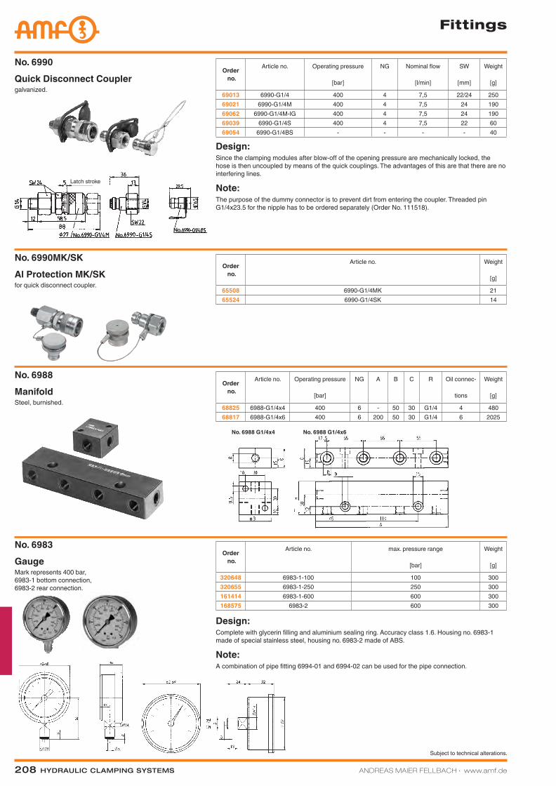
208 Hydraulic clamping SyStemS ANDREAS MAIER FELLBACH ∙ www.amf.de
Subject to technical alterations.
Fittings
No. 6988 G1/4x4 No. 6988 G1/4x6
galvanized. Quick Disconnect CouplerNo. 6990
Order no.
Article no. Operating pressure
[bar]
NG Nominal flow
[l/min]
SW
[mm]
Weight
[g]
69013 6990-G1/4 400 4 7,5 22/24 25069021 6990-G1/4M 400 4 7,5 24 19069062 6990-G1/4M-IG 400 4 7,5 24 19069039 6990-G1/4S 400 4 7,5 22 6069054 6990-G1/4BS - - - - 40
Design:Since the clamping modules after blow-off of the opening pressure are mechanically locked, the hose is then uncoupled by means of the quick couplings. The advantages of this are that there are no interfering lines.
Note:The purpose of the dummy connector is to prevent dirt from entering the coupler. Threaded pin G1/4x23.5 for the nipple has to be ordered separately (Order No. 111518).
Order no.
Article no. Weight
[g]
65508 6990-G1/4MK 2165524 6990-G1/4SK 14
for quick disconnect coupler. Al Protection MK/SKNo. 6990MK/SK
Steel, burnished.ManifoldNo. 6988
Order no.
Article no. Operating pressure
[bar]
NG A B C R Oil connec-
tions
Weight
[g]
68825 6988-G1/4x4 400 6 - 50 30 G1/4 4 48068817 6988-G1/4x6 400 6 200 50 30 G1/4 6 2025
Order no.
Article no. max. pressure range
[bar]
Weight
[g]
320648 6983-1-100 100 300320655 6983-1-250 250 300161414 6983-1-600 600 300168575 6983-2 600 300
Design:Complete with glycerin filling and aluminium sealing ring. Accuracy class 1.6. Housing no. 6983-1 made of special stainless steel, housing no. 6983-2 made of ABS.
Note:A combination of pipe fitting 6994-01 and 6994-02 can be used for the pipe connection.
Mark represents 400 bar, 6983-1 bottom connection, 6983-2 rear connection.
GaugeNo. 6983
Latch stroke
No.No.
No.
Katalog_2012_Hydraulik_EN_ohnePreise.indd 208 3/28/2013 8:40:03 AM
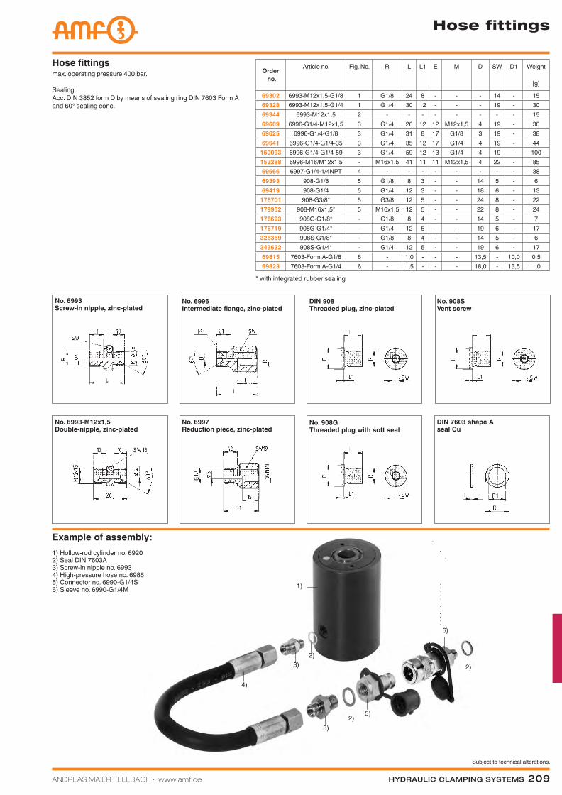
ANDREAS MAIER FELLBACH ∙ www.amf.de Hydraulic clamping SyStemS 209
Subject to technical alterations.
3)
6)
2)
1)
5)
3)
4)
2)2)
max. operating pressure 400 bar.
Sealing: Acc. DIN 3852 form D by means of sealing ring DIN 7603 Form A and 60° sealing cone.
Hose fittings
Hose fittings
Order no.
Article no. Fig. No. R L L1 E M D SW D1 Weight
[g]
69302 6993-M12x1,5-G1/8 1 G1/8 24 8 - - - 14 - 1569328 6993-M12x1,5-G1/4 1 G1/4 30 12 - - - 19 - 3069344 6993-M12x1,5 2 - - - - - - - - 1569609 6996-G1/4-M12x1,5 3 G1/4 26 12 12 M12x1,5 4 19 - 3069625 6996-G1/4-G1/8 3 G1/4 31 8 17 G1/8 3 19 - 3869641 6996-G1/4-G1/4-35 3 G1/4 35 12 17 G1/4 4 19 - 44
160093 6996-G1/4-G1/4-59 3 G1/4 59 12 13 G1/4 4 19 - 100153288 6996-M16/M12x1,5 - M16x1,5 41 11 11 M12x1,5 4 22 - 8569666 6997-G1/4-1/4NPT 4 - - - - - - - - 3869393 908-G1/8 5 G1/8 8 3 - - 14 5 - 669419 908-G1/4 5 G1/4 12 3 - - 18 6 - 13
176701 908-G3/8* 5 G3/8 12 5 - - 24 8 - 22179952 908-M16x1,5* 5 M16x1,5 12 5 - - 22 8 - 24176693 908G-G1/8* - G1/8 8 4 - - 14 5 - 7176719 908G-G1/4* - G1/4 12 5 - - 19 6 - 17326389 908S-G1/8* - G1/8 8 4 - - 14 5 - 6343632 908S-G1/4* - G1/4 12 5 - - 19 6 - 1769815 7603-Form A-G1/8 6 - 1,0 - - - 13,5 - 10,0 0,569823 7603-Form A-G1/4 6 - 1,5 - - - 18,0 - 13,5 1,0
* with integrated rubber sealing
No. 6993Screw-in nipple, zinc-plated
No. 6993-M12x1,5Double-nipple, zinc-plated
No. 6996Intermediate flange, zinc-plated
No. 6997Reduction piece, zinc-plated
No. 908GThreaded plug with soft seal
DIN 7603 shape A seal Cu
Example of assembly:1) Hollow-rod cylinder no. 69202) Seal DIN 7603A3) Screw-in nipple no. 69934) High-pressure hose no. 69855) Connector no. 6990-G1/4S6) Sleeve no. 6990-G1/4M
DIN 908Threaded plug, zinc-plated
No. 908SVent screw
Katalog_2012_Hydraulik_EN_ohnePreise.indd 209 3/28/2013 8:40:07 AM
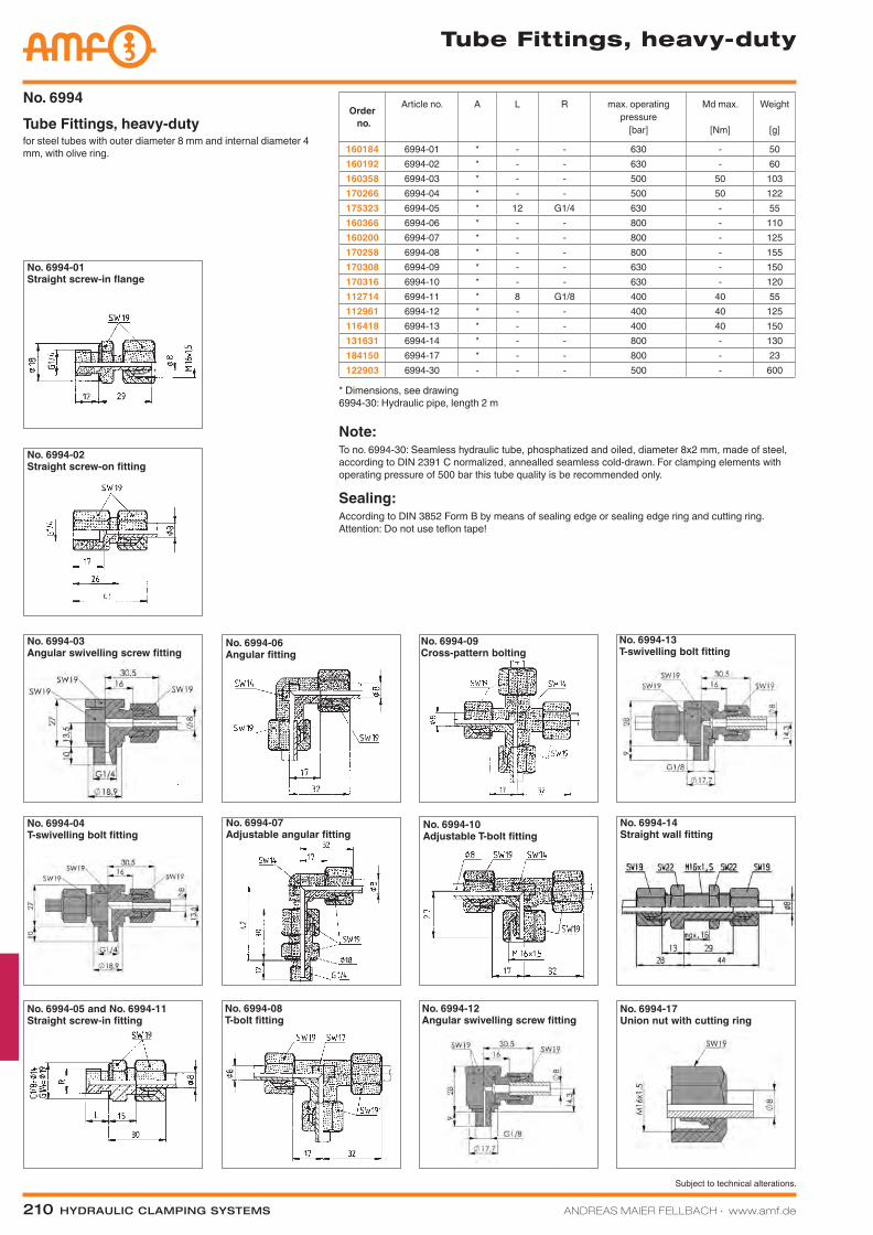
210 Hydraulic clamping SyStemS ANDREAS MAIER FELLBACH ∙ www.amf.de
Subject to technical alterations.
Tube Fittings, heavy-duty
Note:To no. 6994-30: Seamless hydraulic tube, phosphatized and oiled, diameter 8x2 mm, made of steel, according to DIN 2391 C normalized, annealled seamless cold-drawn. For clamping elements with operating pressure of 500 bar this tube quality is be recommended only.
Sealing: According to DIN 3852 Form B by means of sealing edge or sealing edge ring and cutting ring. Attention: Do not use teflon tape!
Order no.
Article no. A L R max. operating pressure
[bar]
Md max.
[Nm]
Weight
[g]
160184 6994-01 * - - 630 - 50160192 6994-02 * - - 630 - 60160358 6994-03 * - - 500 50 103170266 6994-04 * - - 500 50 122175323 6994-05 * 12 G1/4 630 - 55160366 6994-06 * - - 800 - 110160200 6994-07 * - - 800 - 125170258 6994-08 * - - 800 - 155170308 6994-09 * - - 630 - 150170316 6994-10 * - - 630 - 120112714 6994-11 * 8 G1/8 400 40 55112961 6994-12 * - - 400 40 125116418 6994-13 * - - 400 40 150131631 6994-14 * - - 800 - 130184150 6994-17 * - - 800 - 23122903 6994-30 - - - 500 - 600
for steel tubes with outer diameter 8 mm and internal diameter 4 mm, with olive ring.
Tube Fittings, heavy-dutyNo. 6994
* Dimensions, see drawing 6994-30: Hydraulic pipe, length 2 m
No. 6994-03 Angular swivelling screw fitting
No. 6994-04T-swivelling bolt fitting
No. 6994-05 and No. 6994-11Straight screw-in fitting
No. 6994-06 Angular fitting
No. 6994-07 Adjustable angular fitting
No. 6994-08 T-bolt fitting
No. 6994-10 Adjustable T-bolt fitting
No. 6994-14 Straight wall fitting
No. 6994-02Straight screw-on fitting
No. 6994-09 Cross-pattern bolting
No. 6994-17 Union nut with cutting ring
No. 6994-01Straight screw-in flange
No. 6994-13T-swivelling bolt fitting
No. 6994-12 Angular swivelling screw fitting
Katalog_2012_Hydraulik_EN_ohnePreise.indd 210 3/28/2013 8:40:15 AM
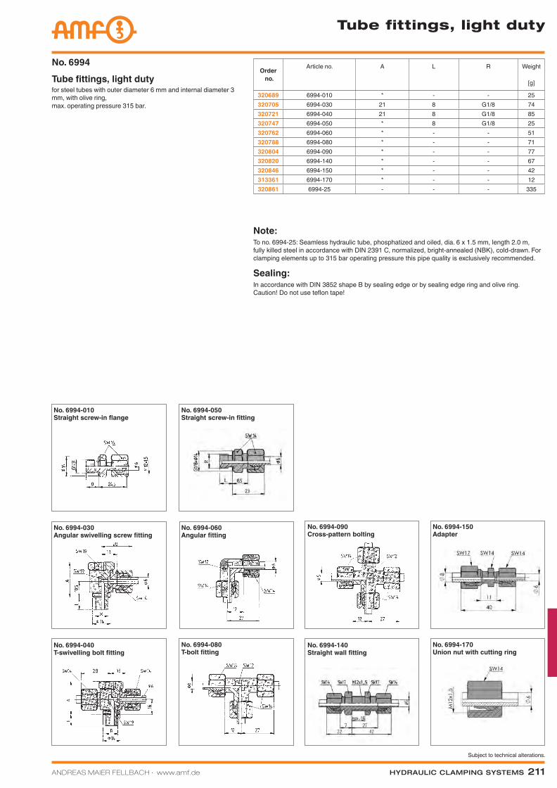
ANDREAS MAIER FELLBACH ∙ www.amf.de Hydraulic clamping SyStemS 211
Subject to technical alterations.
Tube fittings, light duty
for steel tubes with outer diameter 6 mm and internal diameter 3 mm, with olive ring, max. operating pressure 315 bar.
Tube fittings, light dutyNo. 6994
Order no.
Article no. A L R Weight
[g]
320689 6994-010 * - - 25320705 6994-030 21 8 G1/8 74320721 6994-040 21 8 G1/8 85320747 6994-050 * 8 G1/8 25320762 6994-060 * - - 51320788 6994-080 * - - 71320804 6994-090 * - - 77320820 6994-140 * - - 67320846 6994-150 * - - 42313361 6994-170 * - - 12320861 6994-25 - - - 335
Note:To no. 6994-25: Seamless hydraulic tube, phosphatized and oiled, dia. 6 x 1.5 mm, length 2.0 m, fully killed steel in accordance with DIN 2391 C, normalized, bright-annealed (NBK), cold-drawn. For clamping elements up to 315 bar operating pressure this pipe quality is exclusively recommended.
Sealing: In accordance with DIN 3852 shape B by sealing edge or by sealing edge ring and olive ring. Caution! Do not use teflon tape!
No. 6994-030 Angular swivelling screw fitting
No. 6994-040T-swivelling bolt fitting
No. 6994-050Straight screw-in fitting
No. 6994-060 Angular fitting
No. 6994-080 T-bolt fitting
No. 6994-090 Cross-pattern bolting
No. 6994-010Straight screw-in flange
No. 6994-150Adapter
No. 6994-140 Straight wall fitting
No. 6994-170 Union nut with cutting ring
Katalog_2012_Hydraulik_EN_ohnePreise.indd 211 3/28/2013 8:40:21 AM
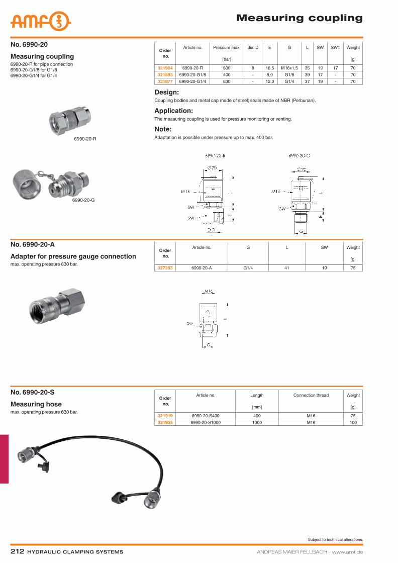
212 Hydraulic clamping SyStemS ANDREAS MAIER FELLBACH ∙ www.amf.de
Subject to technical alterations.
Measuring coupling
6990-20-R for pipe connection6990-20-G1/8 for G1/86990-20-G1/4 for G1/4
Measuring couplingNo. 6990-20
Order no.
Article no. Pressure max.
[bar]
dia. D E G L SW SW1 Weight
[g]
321984 6990-20-R 630 8 16,5 M16x1,5 35 19 17 70321893 6990-20-G1/8 400 - 8,0 G1/8 39 17 - 70321877 6990-20-G1/4 630 - 12,0 G1/4 37 19 - 70
Design:Coupling bodies and metal cap made of steel; seals made of NBR (Perbunan).
Application:The measuring coupling is used for pressure monitoring or venting.
Note:Adaptation is possible under pressure up to max. 400 bar.6990-20-R
6990-20-G
max. operating pressure 630 bar.Adapter for pressure gauge connectionNo. 6990-20-A
Order no.
Article no. G L SW Weight
[g]
327353 6990-20-A G1/4 41 19 75
Order no.
Article no. Length
[mm]
Connection thread Weight
[g]
321919 6990-20-S400 400 M16 75321935 6990-20-S1000 1000 M16 100
max. operating pressure 630 bar.Measuring hoseNo. 6990-20-S
Katalog_2012_Hydraulik_EN_ohnePreise.indd 212 3/28/2013 8:40:27 AM
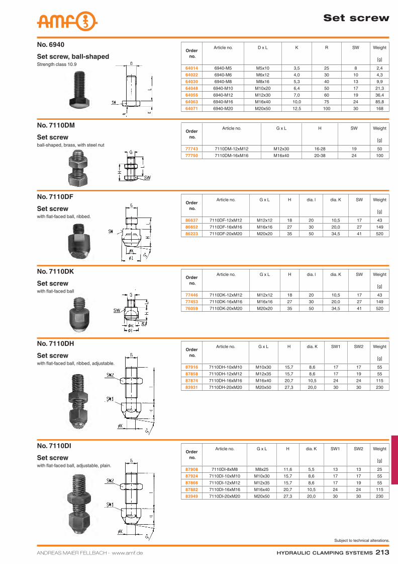
ANDREAS MAIER FELLBACH ∙ www.amf.de Hydraulic clamping SyStemS 213
Subject to technical alterations.
Set screw
Strength class 10.9Set screw, ball-shapedNo. 6940
Order no.
Article no. D x L K R SW Weight
[g]
64014 6940-M5 M5x10 3,5 25 8 2,464022 6940-M6 M6x12 4,0 30 10 4,364030 6940-M8 M8x16 5,3 40 13 9,964048 6940-M10 M10x20 6,4 50 17 21,364055 6940-M12 M12x30 7,0 60 19 36,464063 6940-M16 M16x40 10,0 75 24 85,864071 6940-M20 M20x50 12,5 100 30 168
Order no.
Article no. G x L H SW Weight
[g]
77743 7110DM-12xM12 M12x30 16-28 19 5077750 7110DM-16xM16 M16x40 20-38 24 100
ball-shaped, brass, with steel nutSet screwNo. 7110DM
with flat-faced ball, ribbed.Set screwNo. 7110DF
Order no.
Article no. G x L H dia. l dia. K SW Weight
[g]
86637 7110DF-12xM12 M12x12 18 20 10,5 17 4386652 7110DF-16xM16 M16x16 27 30 20,0 27 14986223 7110DF-20xM20 M20x20 35 50 34,5 41 520
Order no.
Article no. G x L H dia. l dia. K SW Weight
[g]
77446 7110DK-12xM12 M12x12 18 20 10,5 17 4377453 7110DK-16xM16 M16x16 27 30 20,0 27 14976059 7110DK-20xM20 M20x20 35 50 34,5 41 520
with flat-faced ballSet screwNo. 7110DK
Order no.
Article no. G x L H dia. K SW1 SW2 Weight
[g]
87916 7110DH-10xM10 M10x30 15,7 8,6 17 17 5587858 7110DH-12xM12 M12x35 15,7 8,6 17 19 5587874 7110DH-16xM16 M16x40 20,7 10,5 24 24 11583931 7110DH-20xM20 M20x50 27,3 20,0 30 30 230
with flat-faced ball, ribbed, adjustable.Set screwNo. 7110DH
with flat-faced ball, adjustable, plain.Set screwNo. 7110DI
Order no.
Article no. G x L H dia. K SW1 SW2 Weight
[g]
87908 7110DI-8xM8 M8x25 11,6 5,5 13 13 2587924 7110DI-10xM10 M10x30 15,7 8,6 17 17 5587866 7110DI-12xM12 M12x35 15,7 8,6 17 19 5587882 7110DI-16xM16 M16x40 20,7 10,5 24 24 11583949 7110DI-20xM20 M20x50 27,3 20,0 30 30 230
Katalog_2012_Hydraulik_EN_ohnePreise.indd 213 3/28/2013 8:40:28 AM
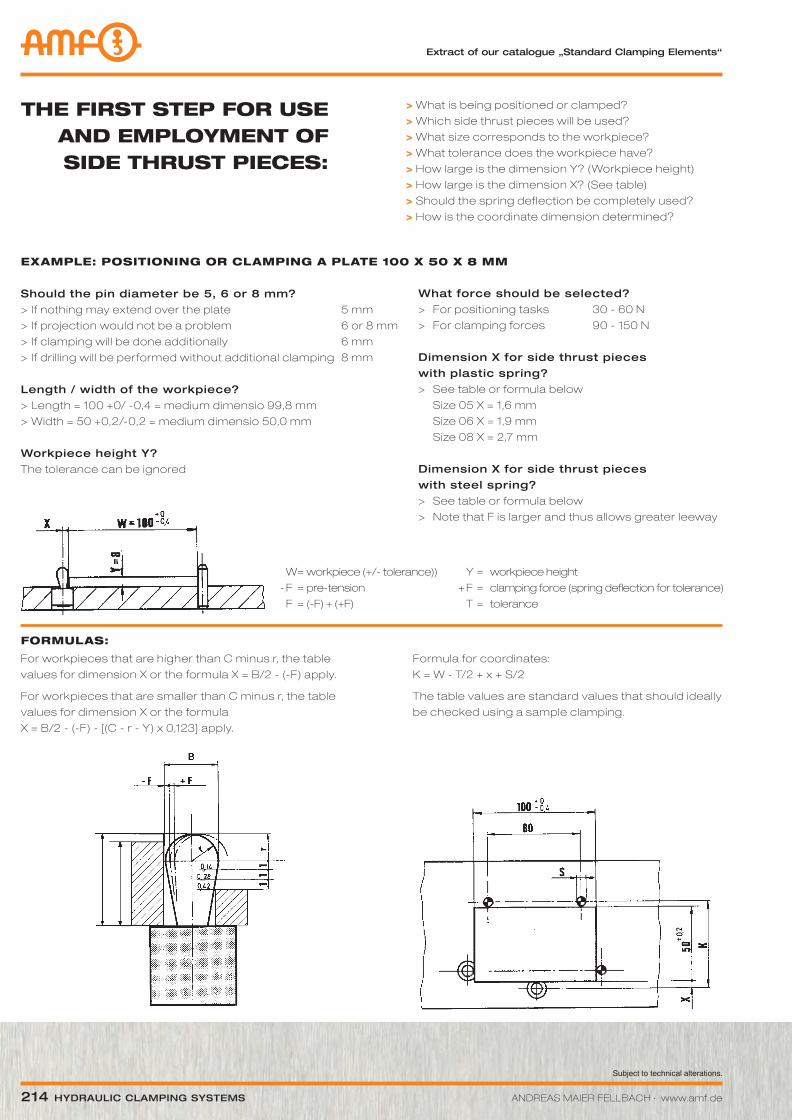
Subject to technical alterations.
214 Hydraulic clamping SyStemS ANDREAS MAIER FELLBACH ∙ www.amf.de
THE FIRST STEP FOR USE AND EMPLOYMENT OF SIDE THRUST PIECES:
> What is being positioned or clamped?
> Which side thrust pieces will be used?
> What size corresponds to the workpiece?
> What tolerance does the workpiece have?
> How large is the dimension y? (Workpiece height)
> How large is the dimension X? (See table)
> Should the spring deflection be completely used?
> How is the coordinate dimension determined?
ExAMPLE: POSITIONING OR CLAMPING A PLATE 100 x 50 x 8 MM
Should the pin diameter be 5, 6 or 8 mm?> If nothing may extend over the plate 5 mm
> If projection would not be a problem 6 or 8 mm
> If clamping will be done additionally 6 mm
> If dril l ing will be performed without additional clamping 8 mm
length / width of the workpiece?> Length = 100 +0/ -0,4 = medium dimensio 99,8 mm
> Width = 50 +0,2/-0,2 = medium dimensio 50,0 mm
workpiece height y?The tolerance can be ignored
what force should be selected?> For positioning tasks 30 - 60 N
> For clamping forces 90 - 150 N
dimension X for side thrust pieces with plastic spring?> See table or formula below
Size 05 X = 1,6 mm
Size 06 X = 1,9 mm
Size 08 X = 2,7 mm
dimension X for side thrust pieces with steel spring?> See table or formula below
> Note that F is larger and thus allows greater leeway
W = workpiece (+/- tolerance)) y = workpiece height
-F =pre-tension +F = clampingforce(springdeflectionfortolerance)
F = (-F) + (+F) T = tolerance
FORMULAS:
For workpieces that are higher than C minus r, the table
values for dimension X or the formula X = B/2 - (-F) apply.
For workpieces that are smaller than C minus r, the table
values for dimension X or the formula
X = B/2 - (-F) - [(C - r - y) x 0,123] apply.
Formula for coordinates:
K = W - T/2 + x + S/2
The table values are standard values that should ideally
be checked using a sample clamping.
extract of our catalogue „Standard clamping elements“
Katalog_2012_Hydraulik_EN_ohnePreise.indd 214 3/28/2013 8:40:29 AM
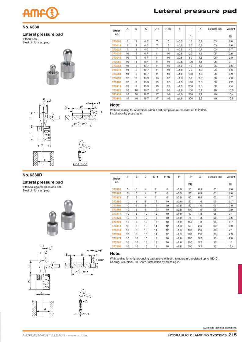
ANDREAS MAIER FELLBACH ∙ www.amf.de Hydraulic clamping SyStemS 215
Subject to technical alterations.
Note:Without sealing for operations without dirt, temperature-resistant up to 250°C. Installation by pressing in.
with seal against chips and dirt. Steel pin for clamping.
Lateral pressure padNo. 6380D
Note:With sealing for chip-producing operations with dirt, temperature-resistant up to 150°C. Sealing: CR, black, 60 Shore. Installation by pressing in.
Lateral pressure pad
without seal. Steel pin for clamping.
Lateral pressure padNo. 6380
Order no.
A B C D -1 H H8 F ~P
[N]
X suitable tool Weight
[g]
373001 6 3 4,0 7 6 ±0,5 10 0,9 03 0,6373019 6 3 4,0 7 6 ±0,5 20 0,9 03 0,6373027 6 3 4,0 7 6 ±0,5 40 0,9 03 0,7373035 10 5 6,7 11 10 ±0,8 20 1,6 05 2,6373043 10 5 6,7 11 10 ±0,8 50 1,6 05 2,9373050 10 5 6,7 11 10 ±0,8 100 1,6 05 3,1373068 10 6 10,7 11 10 ±1,0 40 1,8 06 3,6373076 10 6 10,7 11 10 ±1,0 75 1,8 06 3,6373084 10 6 10,7 11 10 ±1,0 150 1,8 06 3,9373092 12 8 13,9 13 12 ±1,3 50 2,6 08 7,0373100 12 8 13,9 13 12 ±1,3 100 2,6 08 7,2373118 12 8 13,9 13 12 ±1,3 200 2,6 08 7,4373126 16 10 16,7 17 16 ±1,6 100 3,2 10 15,0373134 16 10 16,7 17 16 ±1,6 200 3,2 10 15,4373142 16 10 16,7 17 16 ±1,6 300 3,2 10 15,8
Order no.
A B C D -1 H H8 F ~P
[N]
X suitable tool Weight
[g]
373159 6 3 4 7 6 ±0,5 10 0,9 03 0,6373167 6 3 4 7 6 ±0,5 20 0,9 03 0,6373175 6 3 4 7 6 ±0,5 40 0,9 03 0,7373183 10 5 6 12 10 ±0,8 20 1,6 05 2,7373191 10 5 6 12 10 ±0,8 50 1,6 05 2,9373209 10 5 6 12 10 ±0,8 100 1,6 05 2,9373217 10 6 10 12 10 ±1,0 40 1,8 06 3,1373225 10 6 10 12 10 ±1,0 75 1,8 06 3,6373233 10 6 10 12 10 ±1,0 150 1,8 06 3,7373241 12 8 13 14 12 ±1,3 50 2,6 08 3,9373258 12 8 13 14 12 ±1,3 100 2,6 08 7,1373266 12 8 13 14 12 ±1,3 200 2,6 08 7,3373274 16 10 16 18 16 ±1,6 100 3,2 10 7,6373282 16 10 16 18 16 ±1,6 200 3,2 10 15373290 16 10 16 18 16 ±1,6 300 3,2 10 15,4
Katalog_2012_Hydraulik_EN_ohnePreise.indd 215 3/28/2013 8:40:32 AM
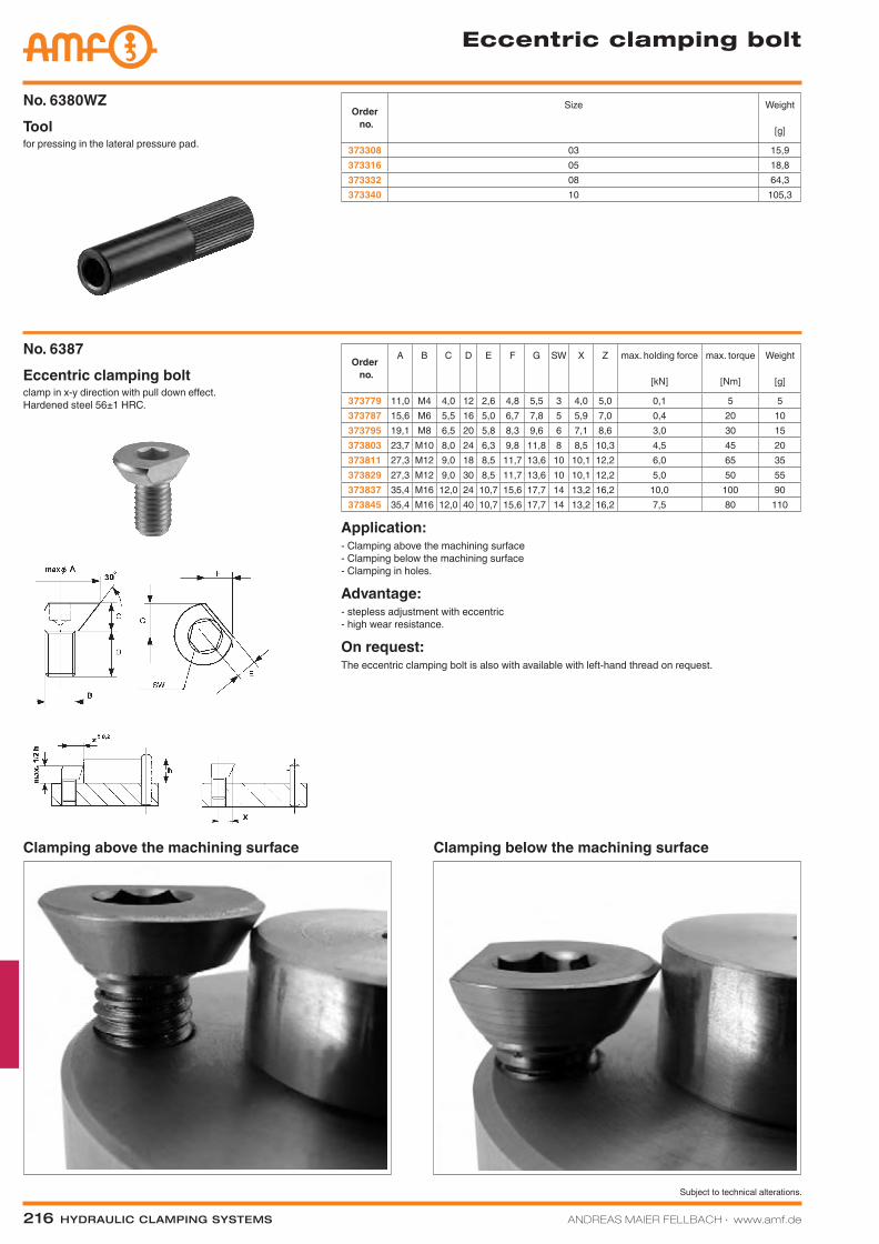
216 Hydraulic clamping SyStemS ANDREAS MAIER FELLBACH ∙ www.amf.de
Subject to technical alterations.
for pressing in the lateral pressure pad.ToolNo. 6380WZ
clamp in x-y direction with pull down effect. Hardened steel 56±1 HRC.
Eccentric clamping boltNo. 6387
Application:- Clamping above the machining surface - Clamping below the machining surface - Clamping in holes.
Advantage:- stepless adjustment with eccentric - high wear resistance.
On request:The eccentric clamping bolt is also with available with left-hand thread on request.
Eccentric clamping bolt
Order no.
Size Weight
[g]
373308 03 15,9373316 05 18,8373332 08 64,3373340 10 105,3
Order no.
A B C D E F G SW X Z max. holding force
[kN]
max. torque
[Nm]
Weight
[g]
373779 11,0 M4 4,0 12 2,6 4,8 5,5 3 4,0 5,0 0,1 5 5373787 15,6 M6 5,5 16 5,0 6,7 7,8 5 5,9 7,0 0,4 20 10373795 19,1 M8 6,5 20 5,8 8,3 9,6 6 7,1 8,6 3,0 30 15373803 23,7 M10 8,0 24 6,3 9,8 11,8 8 8,5 10,3 4,5 45 20373811 27,3 M12 9,0 18 8,5 11,7 13,6 10 10,1 12,2 6,0 65 35373829 27,3 M12 9,0 30 8,5 11,7 13,6 10 10,1 12,2 5,0 50 55373837 35,4 M16 12,0 24 10,7 15,6 17,7 14 13,2 16,2 10,0 100 90373845 35,4 M16 12,0 40 10,7 15,6 17,7 14 13,2 16,2 7,5 80 110
Clamping above the machining surface Clamping below the machining surface
Katalog_2012_Hydraulik_EN_ohnePreise.indd 216 3/28/2013 8:40:34 AM