Embed Size (px)
Citation preview

Mechanized tunnelling in the influence zone of North Anatolianand East Anatolian Faults
By Prof.Dr.Nuh BilginITU Faculty of Mines
Lecture given in ETH on the 18 May 2017
The geology of Turkey is very complex and major North and East AnatolianFault Zones including minor faults associated to these faults zones createtremendous problems, like squeezing the TBM, excessive water ingress, TBMface collapses. SEGMENT COLLAPSES LOOSING TBM AND TUNNEL
Uluabat Koseköy

Understanding North Anatolian and East Anatolian Faults / Pangea Laurasia Gondwana
Pangaea or Pangea was a supercontinent that existed duringthe late Paleozoic and early Mesozoic eras. It assembled fromearlier continental units approximately 335 million years ago,and it began to break apart about 175 million years ago
How did North Anatolian and East Anatolian Faults Formed ?
Reference: Neotectonics and Seismicity of Turkey Prof.Dr.Okan Tüysüz, 2005 TÜ Avrasya Institute

How did North Anatolian and East Anatolian Faults Formed ?
Reference: Neotectonics and Seismicity of Turkey Prof.Dr.Okan Tüysüz, 2005 TÜ Avrasya EnstitüsüReference: Bilgin, N., Çopur,H., Balc ,B TBM Excavation in Difficult Ground Conditions, Case Studiesfrom Turkey, Wiley, Ernst and Son, 2016
Problamatic tunnels opened by NATM in the influence zones of North Anatolian and EastAnatolian Fault Zones
Aya Tunnel.The construction of the railway tunnel between Beypazari and Istanbul (Ari ye Sincan, started in1976, length of 10.064 km). The lined inner diameter of the tunnel is 9.60 m. The tunnel wasexcavated by the NATM and about 230 million USD has been spent on the tunnel construction and itis still not nished. The main reason is the highly complicated geology and the di cult groundconditions. Ayas Tunnel was the longest railway tunnel planned in Turkey, it is abandonned now.Bolu tunnelThis tunnel is within the Trans European Motorway project, and tunnel exaction started on 16 April1993. The total cost of the tunnel is about 300 million USD. It has twin 17 m wide bores, carryingthree lanes of tra c in each direction. The tunnel crosses the North Anatolian Fault. The12 November 1999 the Duzce earthquake (MW = 7.2) caused substantial damage to the tunnel andviaducts, which were under construction at the time of the earthquake. Excavation of the tunnel inthe Ankara to Istanbul direction was completed by the beginning of August 2005, using NATM

The excavation of T26 Tunnel started with NATM method in 2010. The
tunnel is on the North East of Turkey. Due to geological problems, shear
zones, fault zones and low RQD values, the daily advance rates were very
slow. Karakaya formation is the main formation in tunneling area with
Pazarcik melange. Karakaya formation contains fault zones in several
places, this formation has similarities with Karakaya Formation found in
Ulabat Energy Tunnel. Graphitic schist is moderately weathered to fresh
and very weak to weak and is extremely sheared along the foliation
surface.
KÖSEKÖY B LEC K HIGH SPEED TUNNEL
PROBLEMS IN GRAPITIC SHISTS / KÖSEKÖY HIGH SPEED TUNNELMixed ground conditions with ophiolites, graphitic schists and mélanges with boulders including over excavation
were the main difficulties leading to squeezing and blocking of the TBMs or even causing complete failures of the
segments and abandoning of the tunnel. Remedial works are sometimes complex and tedious :reducing the
size of openings, minimal waiting, control of over excavation, lubrication between shield and rock, umbrella
arch, increasing torque and thrust and sometimes rescue galleries are necessary.
13.7 m diameterSingle shield TBM

THE COLLAPSE OF SEGMENTS IN KÖSEKÖY RAILWAY TUNNEL
KÖSEKÖY HIGH SPEED TUNNEL
Face collapses, over excavation and jamming of the cutterhead started at
chainage 216+300m in May 2012 and continued thereafter. TBM
manufacturer decided to close some of the openings within the cutterhead.
After several problems occurred during TBM excavation, the thrust of the TBM
was increased from 84464 kN to 170000kN (breakout) and the torque was
increased from 24083 kN.m (overload) to 36000 kN.m. Face collapsing
continues frequently depending on the weak zones developed within shear
zones, slowing down tremendously advance rates.

Köseköy H gh Speed Tunnel
After several discussions between the consultants, the machine
manufacturer and the contractor, bentonite and foam were decided to be
used to stop face collapses. With several modifications made to TBM, 2
bars of mean face pressure could be obtained. Segments started cracking
in May 2012 and tunnels started collapsing gradually damaging the TBM.
For the sake of safety all tunneling activities were stopped thereafter.
Limited information about this tunnel is given in this speech since the
international dispute is still continuing between the machine
manufacturer and the contractor.
The Effect of closing openings in Köseköy T26 High Speed Tunnel, single shield TBM,D=13,7m
The cost of the electricity when the openings ae not In the area where the openings were openedDate 19.09.2011, Ring 146 150, SE = is 3.57 kWh/m3
.Bentonite application in the area where the openingswere half closed.Date 3 11 2011, Ring 155 165, SE = 12.6 kWh/m3
.The openings are half closed, bentonite is not appliedDate 17.11.2011, Ring 190 199, SE = 7.5 kWh/m3
.Result of closing the openings : High energy consumption,High disc consumption(The cost of electricity when the openings are half
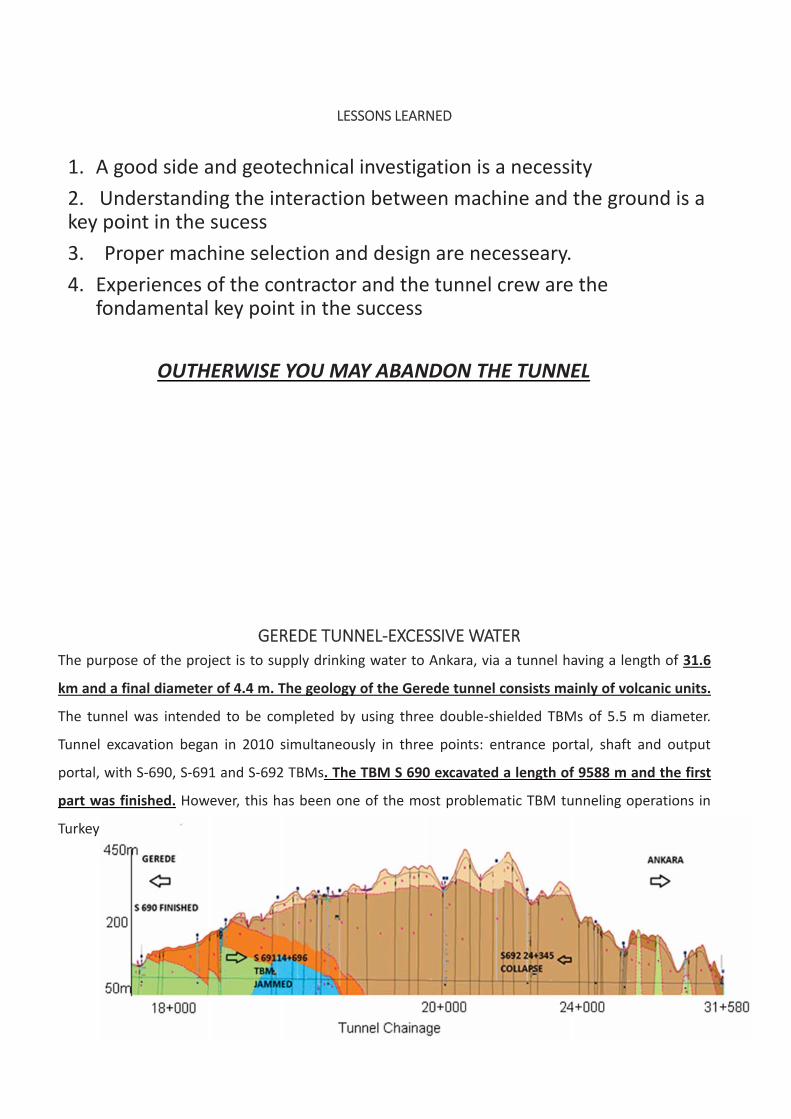
LESSONS LEARNED
1. A good side and geotechnical investigation is a necessity2. Understanding the interaction between machine and the ground is akey point in the sucess3. Proper machine selection and design are necesseary.4. Experiences of the contractor and the tunnel crew are the
fondamental key point in the success
OUTHERWISE YOU MAY ABANDON THE TUNNEL
GEREDE TUNNEL EXCESSIVE WATERThe purpose of the project is to supply drinking water to Ankara, via a tunnel having a length of 31.6
km and a final diameter of 4.4 m. The geology of the Gerede tunnel consists mainly of volcanic units.
The tunnel was intended to be completed by using three double shielded TBMs of 5.5 m diameter.
Tunnel excavation began in 2010 simultaneously in three points: entrance portal, shaft and output
portal, with S 690, S 691 and S 692 TBMs. The TBM S 690 excavated a length of 9588 m and the first
part was finished. However, this has been one of the most problematic TBM tunneling operations in
Turkey

GEREDE TUNNEL
The second drive, which started from the intermediate shaft towards Ankara, was excavated in downstream
direction by the S 691 DS TBM. The TBM became stuck in smectite clay, which has a tremendous swelling
characteristic. Swelling stresses started breaking the segments, and the broken segments were then
supported by steel arches. It is thought that the smectite zone is behaving like a pillar zone, protecting the
tunnel from the highly stressed pressurized water reservoir ahead of the tunnel and so the machine was
removed from this side, and to continue from the Ankara side to take advantage of the dip of the tunnel for
water removal. The third drive, which was being excavated by the S 692 DS, upstream of the Ankaran side,
has been constantly hindered by the complex existing geological conditions of heavily altered and
weathered volcano clastic rocks under very high water tables, which even caused one 12 month stoppage
and required a bypass tunnel. The S 692 shield was trapped at chainage 24+344.86 km after the tunnel
suffered a collapse in July 2014. The pressure deformed the telescopic shield and about 20 m of segmental
lining, as can be seen in following Figure causing a huge water and material inflow, estimated to be around
1250 m3 in 15 minutes
Gerede tunnel
The Machine was destroyed, the area was collapsed. A new TBM was ordered in2015, a bypass tunnel was excavated by a new TBM

Uluabat Tunnel
The working area is situated on the southern part of Uluabat Bursa(Apolyont) Lake, Turkey. The tunnel, with a length 11.4 km, started to beexcavated with a 5.05 m diameter EPB TBM from chainage June 2006,and terminated in March 2010. The geology is consisted of Karakayaformation of Triassic age with meta detritic rocks such as fi ne grainedmeta claystone, meta siltstone, meta sandstone and graphitic schists.During the tunnel excavation, the TBM was jammed several times due tothe highly squeezing characteristics of the Karakaya formation. Eighteenrescue galleries were constructed to free the trapped TBM, and 192days were spent in TBM rescue operations. Detailed study of the TBMperformance data showed that overburden, RMR, Q values, the increaseof machine thrust for a given tunnel length and time, the variation in thetorque/thrust ratio can all be used as a reliable basis to alert thepracticing engineers to implement some mitigating measures, such asusing bentonite injection around the TBM shield
ULUABAT TUNNEL
The working area is situated on the southern part of Uluabat Bursa (Apolyont)
Lake, Turkey. The tunnel, with a length 11.4 km, started to be excavated with a
5.05 m diameter EPB TBM from chainage 11+465 km in June 2006, and terminated
in March 2010, at chainage 1+792 km. The tunnel route within chainages 11+465 to
7+750 km and 6+000 to 1+792 km consisted of Karakaya formation of Triassic age
with meta detritic rocks such as fine grained meta claystone, meta siltstone, meta
sandstone and graphitic schists.

ULUABAT TUNNEL
Uluabat Tunnel and Squeezing FormatIons

MITIGATIONMEASURES TO OVERCOME TRAPPED TBM IN ULUABAT TUNNEL
For a first initiation, the fixed overcut was increased from 35 mm eventually to 95
mm on the radius. However, this was not found sufficient in some area and the
bentonite injection was utilized in critical points. This was accomplished by pumping
a bentonite mixture between the shield skin and the ground, with the aim of reducing
frictional forces. The bentonite mixture was delivered to the shield in a mixing car, to
keep it fluid. Injection through 2 inch diameter ports, six in total, was done . Delivery
pressure depended on the proximity of the ground at the injection points, and varied
between 0.2 bar and 2.5 bars when ground squeezing had reduced the clear ance gap
(overcut). Two to three cubic meters of the thin bentonite solution was used for each
advance.
MITIGATIONMEASURES TO OVERCOME TRAPPED TBM IN ULUABAT TUNNEL
Steel plates of 20 mm in thickness were welded to the TBM skin surface aroundinjection ports to facilitate the injection. The aim was to produce a groove to permitbentonite injection; since excessive ground squeezing sealed the injection ports sostrongly that bentonite could not be pumped even at pressures in excess of 10 bars.The exception to this statement occurred when the TBM was stopped for a long time,and the ground squeezed down even around the raised plates, consequently sealingthe outlet. The jamming of the shield was not encountered between the chainageswhere the bentonite was applied, due to the reduction of friction between the shieldand the rock. It is also important to note that welding of steel plates of 20 mm tothe TBM skin surface around injection ports facilitated the injection.

TBM SQUEEZING IN DO ANÇAY TUNNEL DUE TO TECTONIC STRESSES
The Dogancay tunnel is located in the North East of Turkey, affected by North
Anatolian Fault, and it is a part of a hydroelectric project licensed by Enerji Sa. The
tunnel length is 6655 m, and the excavation started in September 2012 and ended in
July 2015 (5.5 m/day). The tunnel was excavated by a double shield Herrenknecht
having a diameter of 4.1 m. The tunnel route contains limestone, shale, siltstone,
claystone, sandstone and quartzite. The overburden within 3 km of the tunnel route is
around 1,000 m and only two boreholes could be opened in the tunnel route prior to
starting the excavation. Tectonic stresses squeezed the TBM several times, causing
considerable delays in tunnel drivage. T he followingFigure shows the general layout of
the tunnel route with the main faults (F1, F2 etc.)
Do ançay Tunnel

DO ANÇAY TUNNEL
The ratio of torque to thrust force is a good indicator of the squeezing ofa TBM. The following Figure shows the variation of this ratio between12.04.2015 and 14.04.2015. As can clearly be seen from this figure theratio started at 2, and dropped to 0.5 by the 7th ring, then later increasedup to 1.5 and dropped again to 0.5, and the TBM was jammed within the25th ring.
Kargi Hepp Tunnel AFFECTED BY EAST ANADOLIAN FAULT Probe dr ll
Kargi Hydropower project is situated in the region of Kizilirmak River between the town of
Osmancik and the Boyabat reservoir. The excavation of an 11.8 km tunnel has been
recently finished, 7.8 km of the tunnel was excavated with a double shield Robbins TBM
of 9.84 m diameter, and 4 km of the tunnel was opened with NATM. However due to
geological difficulties, and North Anatolian Fault Zone the ground became blocky in
character, TBM stuck several times and galleries were opened in different places to rescue
the trapped cutterhead. To overcome the difficulties in continuing the project, systematic
probe drilling and umbrella arch (UA) were selected as remedial works.

BLASTING THE GROUND TO FREE THE TRAPPED TBM SURUÇ TUNNEL
Eleven ports existed in the front shield of TBM. Drillings for UA started approximately 3 meters behind the cutter head.Drill pipes having diameter of 3 inches were used for UA. At the be ginning of the operation the holes were drilled witha drilling bit attached to drill pipes. After removing the drill bit, a string of perforated pipes for injection, was placedinto drill hole. Injection was done up to 120 bars pressure, depending on injection materials properties. For injectionfast setting micro fine Portland cement (Rheocem 650) was used. Moreover along with micro cement, two componentpolyurethane injection resin (MasterRoc MP 355 and Geofoam) were also used. For filling very large voids, twocomponent urea silicate (MasterRoc MP 367) injection was realized. Generally 15 meters of drill holes having anapproximate of 20° angle were realized with 4 meter overlaps be tween drills. It was seen that one umbrella arch drill,permits to support approximately 4 ring excavations, which is 6 meters in length .

Probe Dr ll ng In Karg TUNNEL
DRILLING FOR Umbrella Arch

INTERPRETATION OF DRILLING DATA
Kargi HEPP Project UMBRELLA ARCH

MELENWATER TUNNEL UNDER THE INLUENCE ZONE OF NORTH ANATOLIAN FAULTAND POBLEM OF DYKES

PROBLEMS OF DYKES AND PROB DRILLING
EFFECTS OF DYKES, BLOCKY GROUND AND REMEDIAL WORKS
Dykes cutting the Paleozoic sedimentary rocks in the Istanbul region is known well by practicing tunnel
engineers. These andesitic rocks, which are generally considered to be of Cretaceous age, make
fractures in the country rock and cause several problems during TBM excavation such as blocking the
cutterhead and excessive disc cutter consumption. Typical examples are the Goztepe Kadikoy Metro
tunnels, and tThe foloowing Figure shows typical big blocks coming from the interface of a dyke and
the main rock formation causing the blockage of the cutterhead in different areas.
Big blocks coming from the face in Goztepe Kadikoy Metro Tunnel.
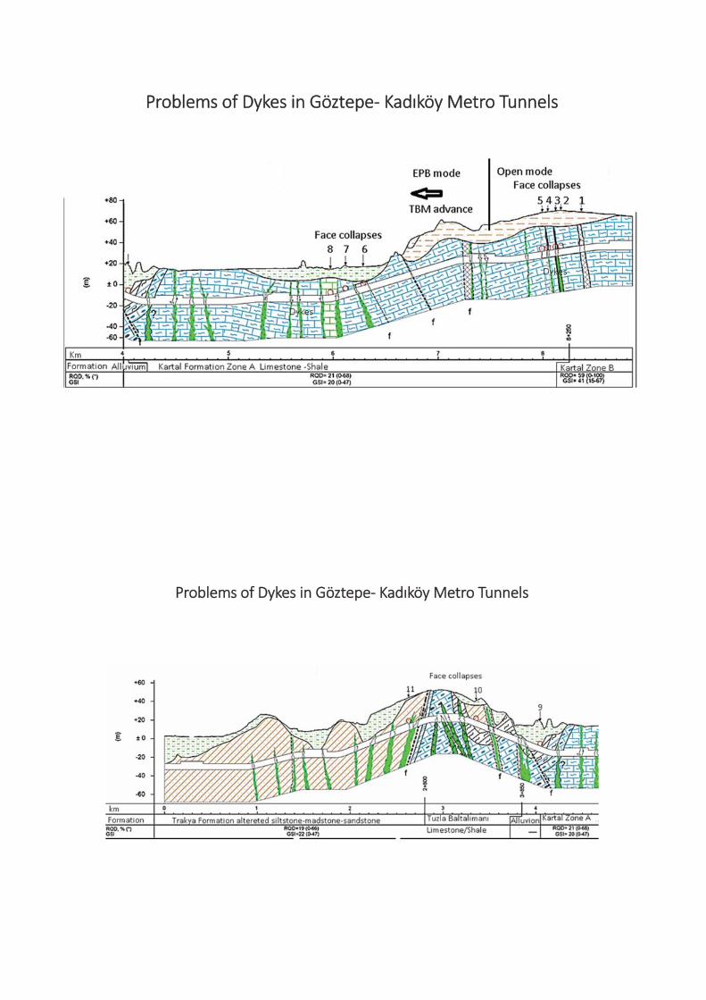
Problems of Dykes in Göztepe Kad köy Metro Tunnels
Problems of Dykes in Göztepe Kad köy Metro Tunnels

TBM Blockages in Göztepe Kad köy Metro Tunnels
AreaLine No Ring No Tunnel m Stoppage Cause of the problem
1 1 73 8+366 27days Fault zone
2 2 260–279 8+170 14 days Contact zone between dyke and Kartal Formation
Opening ratio was reduced by adding grizzly bars on the TBM cutterhead
3 1 232 8+120 7.5 days Contact zone between dyke and Kartal Formation
4 1 282 8+046 2 days Contact zone between dyke and Kartal Formation
5 1 321 7+993 6 days Contact zone between dyke and Kartal Formation
Screw conveyor was mounted within the cutting chamber and EPB mode was used thereafter
6 2 1349 6+286 2.5 days Fault zone
7 2 1461 6+118 3 days Contact zone between dyke and Kartal Formation
8 1 1483 5+973 1 day Dyke contact zone
9 1 2272 4+046 2.5 days Fault zone
10 1 2731 3+356 3 days Transition zone between Trakya and Baltalimani Formation.
11 1 3021 2+628 24.5 days Shear zone next to the tunnel connection
EFFECTS OF DYKES, BLOCKY GROUND AND REMEDIAL WORKSFigure
The remedial work was to put some grizzly bars within the openings of the cutterhead. Figure 1 shows the cutterhead ofTBM used in Goztepe–Kadikoy Metro tunnel and Figure 2 shows the cutterhead after modification with grizzly bars. Theeffect of remedial work is clearly seen in Figure 3 showing that the mean advance rate was 3 m/day and this valueincreased up to 7 m/day after the modification of the cutterhead. However, it is interesting to note that the dailyadvance rate in creased to 10 m (day) after installing screw conveyor within the TBM chamber and passing to EarthPressure Balance (EPB) mode. Mean time in different tunnels in Istanbul same remedial works were carried out forBeykoz and Marmaray Tunnels . Figure 3 shows TBM performance before and after TBM modification
Figure 1 2. Cutterhead before and after modification in GoztepeKadikoy Metro Tunnel.
Figure 3. TBM performance before and after TBMmodification.

The wear of twin disc cutter due of stalling disc cutter in blocky ground.
In November 2008, during the excavation of Goztepe Kadikoy Metro tunnel with a 6.6 m EPB TBM in blocky sandstone it
was reported that thrust force started increasing from 10000 kN gradually up 19860 kN, however, this was reverse for
torque decreasing from 2.7 MNm down to 1.6 within the same rings. This phenomenon is illustrated in the following
Figures. This is typical behavior of chisel cutters or rippers where the cutting force (equivalent to torque) is less than
normal force (or thrust) in most cases. The operation was stopped to check the cutterhead. It was noticed that 6 center
double discs and 4 single discs were flattened as seen in Figure below and one disc were destroyed completely. The
careful observation of checking the change in thrust and torque values of TBM prevented demolishing the cutterhead.
The increase of thrust force due tostalling of disc cutters in blocky ground.
The decrease of torque due of stallingof disc cutters in blocky ground.
The wear of twin disc cutter due of stalling disccutter in blocky ground.
CLOGGING OF THE CUTTERHEAD
Clogging of the cutterhead in clayey rock for mations is one of the major problems which de creasesthe daily advance rates as encountered in Suruc Water Tunnel. The main rock formation in this tunnelis marl and clayey limestone. XRD anal ysis showed that clay minerals such as kaolinite caused cloggingof the TBM cutterhead. Anti clogging agents are needed in most case to stop the clogging effect. TheFigure given below is a typical example showing the effect of clogging on thrust and normal forces ofTBM
Effect of clogging the cutterhead in Suruc Tunnel
NURDA I TUNNEL
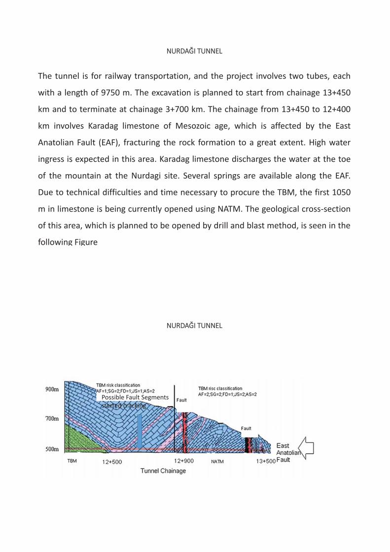
The tunnel is for railway transportation, and the project involves two tubes, each
with a length of 9750 m. The excavation is planned to start from chainage 13+450
km and to terminate at chainage 3+700 km. The chainage from 13+450 to 12+400
km involves Karadag limestone of Mesozoic age, which is affected by the East
Anatolian Fault (EAF), fracturing the rock formation to a great extent. High water
ingress is expected in this area. Karadag limestone discharges the water at the toe
of the mountain at the Nurdagi site. Several springs are available along the EAF.
Due to technical difficulties and time necessary to procure the TBM, the first 1050
m in limestone is being currently opened using NATM. The geological cross section
of this area, which is planned to be opened by drill and blast method, is seen in the
following Figure
NURDA I TUNNEL
Possible Fault Segmentsstarted cracking

Nurda TunnelThe length of the two tubes railway tunnel is 9750 m and diameter is 8 mIt was decided to open the first 1000 m of the tunnel by NATM since the
tunnel was under the influence of East Anatolian Fault
The length of the tunnel is T
Risk Classification System for Using TBM
The tunnels excavated close to the NAF and EAF led to the development of a risk classification
method defined in the following Table. According to this table, the use of a TBM in the Nurdagi
tunnel at 13+500 to 12+800 km is very risky, 12+800 to 12+500 km is risky and it is favorable up to
4+850 kmFactors effecting the risk of using TBMs Classification1. Distance of the tunnel to NAF and EAF, thepossibility of tectonic stresses. AF
1. Within 0.5–2 km of NAF and EAF
2. Very close to NAF and EAF2. The possibility of large amounts of water ingressinto the tunnel. Detailed geological reports and carefulobservation of drilling logs are necessary. SG
1. Less than 100 lt/sec
2. More than 100 lt/sec3. The possibility of seeing geological discontinuities infront of tunnel face. The criterion is that in NATM it iseasy to see and control geological discontinuities inthe tunnel face. FD
1. Easy
2. Difficult
4. Geological discontinuities, RMR, Q, JS 1. Q, RMR
2. Q, RMR5. The presence of anticlinal and synclinal AS 1. One per 1 km
2. More than one per 1 kmIf the total mark is 8–10, it is very risky to use TBM; if the total mark is 5–8, it is risky; if the total mark is2–5, the risk of using TBM is in medium level; if the total mark is 0–2, using TBM is not risky.

Typical effect of Nort Anatolian Fault in the rockformation
Portal in Nurda tunnel

Nurda Tünelinde kullan lan tek kalkanl Robbins TBMSS268 398
You may find somemore information inthis book which waspublished in 2016
DRIVING A TBM IN A DIFFICULT GROUND IS NOT A JOKE IT NEEDS ANINTERNATIONAL GROUP OF EXPERTS FOR A SUCCESS, AS IN MELEN
(From USA, Switzerland and Turkey) AND EUROSIA TUNNEL (From USA,Germany, UAS and Turkey)
THANK YOU LISTENING TO ME