Embed Size (px)
Citation preview
Sense & Control
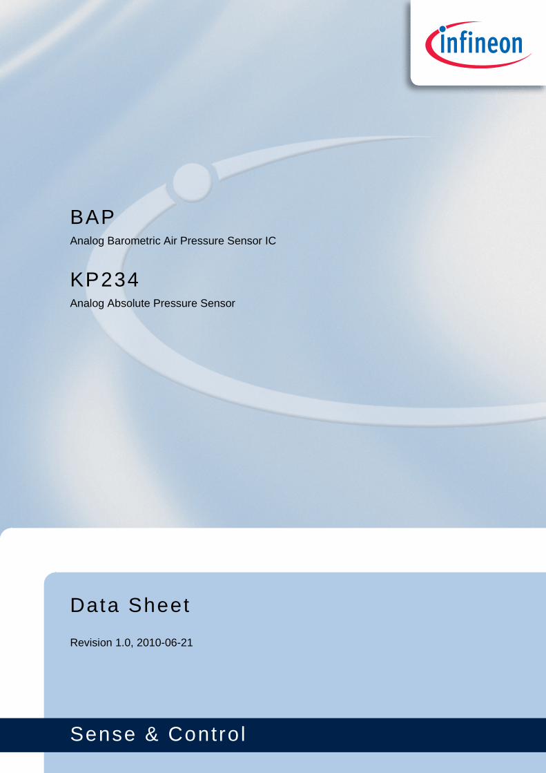
Data Sheet
Revision 1.0, 2010-06-21
KP234Analog Absolute Pressure Sensor
BAPAnalog Barometric Air Pressure Sensor IC
Edition 2010-06-21
Published byInfineon Technologies AG81726 Munich, Germany© 2010 Infineon Technologies AGAll Rights Reserved.
Legal Disclaimer
The information given in this document shall in no event be regarded as a guarantee of conditions or characteristics. With respect to any examples or hints given herein, any typical values stated herein and/or any information regarding the application of the device, Infineon Technologies hereby disclaims any and all warranties and liabilities of any kind, including without limitation, warranties of non-infringement of intellectual property rights of any third party.
Information
For further information on technology, delivery terms and conditions and prices, please contact the nearest Infineon Technologies Office (www.infineon.com ).
Warnings
Due to technical requirements, components may contain dangerous substances. For information on the types in question, please contact the nearest Infineon Technologies Office.Infineon Technologies components may be used in life-support devices or systems only with the express written approval of Infineon Technologies, if a failure of such components can reasonably be expected to cause the failure of that life-support device or system or to affect the safety or effectiveness of that device or system. Life support devices or systems are intended to be implanted in the human body or to support and/or maintain and sustain and/or protect human life. If they fail, it is reasonable to assume that the health of the user or other persons may be endangered.

KP234Analog Absolute Pressure Sensor
Data Sheet 3 Revision 1.0, 2010-06-21
KP234Analog Absolute Pressure Sensor
Data Sheet 4 Revision 1.0, 2010-06-21
Trademarks of Infineon Technologies AG
A-GOLD™, BlueMoon™, COMNEON™, CONVERGATE™, COSIC™, C166™, CROSSAVE™, CanPAK™,CIPOS™, CoolMOS™, CoolSET™, CONVERPATH™, CORECONTROL™, DAVE™, DUALFALC™, DUSLIC™,EasyPIM™, EconoBRIDGE™, EconoDUAL™, EconoPACK™, EconoPIM™, E-GOLD™, EiceDRIVER™,EUPEC™, ELIC™, EPIC™, FALC™, FCOS™, FLEXISLIC™, GEMINAX™, GOLDMOS™, HITFET™,HybridPACK™, INCA™, ISAC™, ISOFACE™, IsoPACK™, IWORX™, M-GOLD™, MIPAQ™, ModSTACK™,MUSLIC™, my-d™, NovalithIC™, OCTALFALC™, OCTAT™, OmniTune™, OmniVia™, OptiMOS™,OPTIVERSE™, ORIGA™, PROFET™, PRO-SIL™, PrimePACK™, QUADFALC™, RASIC™, ReverSave™,SatRIC™, SCEPTRE™, SCOUT™, S-GOLD™, SensoNor™, SEROCCO™, SICOFI™, SIEGET™,SINDRION™, SLIC™, SMARTi™, SmartLEWIS™, SMINT™, SOCRATES™, TEMPFET™, thinQ!™,TrueNTRY™, TriCore™, TRENCHSTOP™, VINAX™, VINETIC™, VIONTIC™, WildPass™, X-GOLD™, XMM™,X-PMU™, XPOSYS™, XWAY™.
Other Trademarks
AMBA™, ARM™, MULTI-ICE™, PRIMECELL™, REALVIEW™, THUMB™ of ARM Limited, UK. AUTOSAR™ islicensed by AUTOSAR development partnership. Bluetooth™ of Bluetooth SIG Inc. CAT-iq™ of DECT Forum.COLOSSUS™, FirstGPS™ of Trimble Navigation Ltd. EMV™ of EMVCo, LLC (Visa Holdings Inc.). EPCOS™ ofEpcos AG. FLEXGO™ of Microsoft Corporation. FlexRay™ is licensed by FlexRay Consortium.HYPERTERMINAL™ of Hilgraeve Incorporated. IEC™ of Commission Electrotechnique Internationale. IrDA™ ofInfrared Data Association Corporation. ISO™ of INTERNATIONAL ORGANIZATION FOR STANDARDIZATION.MATLAB™ of MathWorks, Inc. MAXIM™ of Maxim Integrated Products, Inc. MICROTEC™, NUCLEUS™ ofMentor Graphics Corporation. Mifare™ of NXP. MIPI™ of MIPI Alliance, Inc. MIPS™ of MIPS Technologies, Inc.,USA. muRata™ of MURATA MANUFACTURING CO. OmniVision™ of OmniVision Technologies, Inc.Openwave™ Openwave Systems Inc. RED HAT™ Red Hat, Inc. RFMD™ RF Micro Devices, Inc. SIRIUS™ ofSirius Sattelite Radio Inc. SOLARIS™ of Sun Microsystems, Inc. SPANSION™ of Spansion LLC Ltd. Symbian™of Symbian Software Limited. TAIYO YUDEN™ of Taiyo Yuden Co. TEAKLITE™ of CEVA, Inc. TEKTRONIX™of Tektronix Inc. TOKO™ of TOKO KABUSHIKI KAISHA TA. UNIX™ of X/Open Company Limited. VERILOG™,PALLADIUM™ of Cadence Design Systems, Inc. VLYNQ™ of Texas Instruments Incorporated. VXWORKS™,WIND RIVER™ of WIND RIVER SYSTEMS, INC. ZETEX™ of Diodes Zetex Limited.
Last Trademarks Update 2009-10-19
KP234 Analog Absolute Pressure Sensor
Revision History: 2010-06-21, Revision 1.0
Previous Revision: Revision 0.9.1
Page Subjects (major changes since last revision)
Page 17 Comment about application circuit example added
Page 18 Thermal resistance specified according JESD51-2
Change document status from preliminary to final
KP234Analog Absolute Pressure Sensor
Table of Contents
Data Sheet 5 Revision 1.0, 2010-06-21
Table of Contents . . . . . . . . . . . . . . . . . . . . . . . . . . . . . . . . . . . . . . . . . . . . . . . . . . . . . . . . . . . . . . . . 5
List of Figures . . . . . . . . . . . . . . . . . . . . . . . . . . . . . . . . . . . . . . . . . . . . . . . . . . . . . . . . . . . . . . . . . . . 6
List of Tables . . . . . . . . . . . . . . . . . . . . . . . . . . . . . . . . . . . . . . . . . . . . . . . . . . . . . . . . . . . . . . . . . . . . 7
1 Product Description . . . . . . . . . . . . . . . . . . . . . . . . . . . . . . . . . . . . . . . . . . . . . . . . . . . . . . . . . . . . . . 81.1 Features . . . . . . . . . . . . . . . . . . . . . . . . . . . . . . . . . . . . . . . . . . . . . . . . . . . . . . . . . . . . . . . . . . . . . . . . 81.2 Target Applications . . . . . . . . . . . . . . . . . . . . . . . . . . . . . . . . . . . . . . . . . . . . . . . . . . . . . . . . . . . . . . . . 8
2 Functional Description . . . . . . . . . . . . . . . . . . . . . . . . . . . . . . . . . . . . . . . . . . . . . . . . . . . . . . . . . . . . 92.1 Pin Configuration . . . . . . . . . . . . . . . . . . . . . . . . . . . . . . . . . . . . . . . . . . . . . . . . . . . . . . . . . . . . . . . . 102.2 Pin Description . . . . . . . . . . . . . . . . . . . . . . . . . . . . . . . . . . . . . . . . . . . . . . . . . . . . . . . . . . . . . . . . . . 102.3 Block Diagram . . . . . . . . . . . . . . . . . . . . . . . . . . . . . . . . . . . . . . . . . . . . . . . . . . . . . . . . . . . . . . . . . . 112.4 Transfer Function . . . . . . . . . . . . . . . . . . . . . . . . . . . . . . . . . . . . . . . . . . . . . . . . . . . . . . . . . . . . . . . . 122.5 Accuracy . . . . . . . . . . . . . . . . . . . . . . . . . . . . . . . . . . . . . . . . . . . . . . . . . . . . . . . . . . . . . . . . . . . . . . . 132.5.1 Ratiometric Error . . . . . . . . . . . . . . . . . . . . . . . . . . . . . . . . . . . . . . . . . . . . . . . . . . . . . . . . . . . . . . . 132.5.2 Overall Accuracy . . . . . . . . . . . . . . . . . . . . . . . . . . . . . . . . . . . . . . . . . . . . . . . . . . . . . . . . . . . . . . . 132.6 Output Voltage versus Load . . . . . . . . . . . . . . . . . . . . . . . . . . . . . . . . . . . . . . . . . . . . . . . . . . . . . . . . 152.7 Timing Properties . . . . . . . . . . . . . . . . . . . . . . . . . . . . . . . . . . . . . . . . . . . . . . . . . . . . . . . . . . . . . . . . 16
3 Specification . . . . . . . . . . . . . . . . . . . . . . . . . . . . . . . . . . . . . . . . . . . . . . . . . . . . . . . . . . . . . . . . . . . 173.1 Application Circuit Example . . . . . . . . . . . . . . . . . . . . . . . . . . . . . . . . . . . . . . . . . . . . . . . . . . . . . . . . 173.2 Absolute Maximum Ratings . . . . . . . . . . . . . . . . . . . . . . . . . . . . . . . . . . . . . . . . . . . . . . . . . . . . . . . . 183.3 Operating Range . . . . . . . . . . . . . . . . . . . . . . . . . . . . . . . . . . . . . . . . . . . . . . . . . . . . . . . . . . . . . . . . 193.4 Characteristics . . . . . . . . . . . . . . . . . . . . . . . . . . . . . . . . . . . . . . . . . . . . . . . . . . . . . . . . . . . . . . . . . . 20
4 Package Information . . . . . . . . . . . . . . . . . . . . . . . . . . . . . . . . . . . . . . . . . . . . . . . . . . . . . . . . . . . . 224.1 PG-DSOF-8-16 Outline . . . . . . . . . . . . . . . . . . . . . . . . . . . . . . . . . . . . . . . . . . . . . . . . . . . . . . . . . . . . 224.2 Identification Code . . . . . . . . . . . . . . . . . . . . . . . . . . . . . . . . . . . . . . . . . . . . . . . . . . . . . . . . . . . . . . . 23
Table of Contents
KP234Analog Absolute Pressure Sensor
List of Figures
Data Sheet 6 Revision 1.0, 2010-06-21
Figure 1 Pin configuration (top view, figure not to scale) . . . . . . . . . . . . . . . . . . . . . . . . . . . . . . . . . . . . . . . 10Figure 2 Functional block diagram . . . . . . . . . . . . . . . . . . . . . . . . . . . . . . . . . . . . . . . . . . . . . . . . . . . . . . . . 11Figure 3 Transfer function. . . . . . . . . . . . . . . . . . . . . . . . . . . . . . . . . . . . . . . . . . . . . . . . . . . . . . . . . . . . . . . 12Figure 4 Ratiometric error . . . . . . . . . . . . . . . . . . . . . . . . . . . . . . . . . . . . . . . . . . . . . . . . . . . . . . . . . . . . . . . 13Figure 5 Accuracy for pressure acquisition. . . . . . . . . . . . . . . . . . . . . . . . . . . . . . . . . . . . . . . . . . . . . . . . . . 14Figure 6 Maximum output voltage limit with pull-down load . . . . . . . . . . . . . . . . . . . . . . . . . . . . . . . . . . . . . 15Figure 7 Minimum output voltage limit with pull-up load . . . . . . . . . . . . . . . . . . . . . . . . . . . . . . . . . . . . . . . . 15Figure 8 Power-up time. . . . . . . . . . . . . . . . . . . . . . . . . . . . . . . . . . . . . . . . . . . . . . . . . . . . . . . . . . . . . . . . . 16Figure 9 Response and stabilization time . . . . . . . . . . . . . . . . . . . . . . . . . . . . . . . . . . . . . . . . . . . . . . . . . . . 16Figure 10 Application circuit example . . . . . . . . . . . . . . . . . . . . . . . . . . . . . . . . . . . . . . . . . . . . . . . . . . . . . . . 17Figure 11 Package outline (all dimensions in mm) . . . . . . . . . . . . . . . . . . . . . . . . . . . . . . . . . . . . . . . . . . . . . 22Figure 12 Identification Code . . . . . . . . . . . . . . . . . . . . . . . . . . . . . . . . . . . . . . . . . . . . . . . . . . . . . . . . . . . . . 23
List of Figures
KP234Analog Absolute Pressure Sensor
List of Tables
Data Sheet 7 Revision 1.0, 2010-06-21
Table 1 Pin Description . . . . . . . . . . . . . . . . . . . . . . . . . . . . . . . . . . . . . . . . . . . . . . . . . . . . . . . . . . . . . . . . 10Table 2 Transfer function. . . . . . . . . . . . . . . . . . . . . . . . . . . . . . . . . . . . . . . . . . . . . . . . . . . . . . . . . . . . . . . 12Table 3 Ratiometric Error. . . . . . . . . . . . . . . . . . . . . . . . . . . . . . . . . . . . . . . . . . . . . . . . . . . . . . . . . . . . . . . 13Table 4 Accuracy . . . . . . . . . . . . . . . . . . . . . . . . . . . . . . . . . . . . . . . . . . . . . . . . . . . . . . . . . . . . . . . . . . . . . 14Table 5 Component Values . . . . . . . . . . . . . . . . . . . . . . . . . . . . . . . . . . . . . . . . . . . . . . . . . . . . . . . . . . . . 17Table 6 Absolute Maximum Ratings . . . . . . . . . . . . . . . . . . . . . . . . . . . . . . . . . . . . . . . . . . . . . . . . . . . . . . 18Table 7 Operating Range . . . . . . . . . . . . . . . . . . . . . . . . . . . . . . . . . . . . . . . . . . . . . . . . . . . . . . . . . . . . . . 19Table 8 Electrical Characteristics . . . . . . . . . . . . . . . . . . . . . . . . . . . . . . . . . . . . . . . . . . . . . . . . . . . . . . . . 20Table 9 Transfer Function . . . . . . . . . . . . . . . . . . . . . . . . . . . . . . . . . . . . . . . . . . . . . . . . . . . . . . . . . . . . . . 21
List of Tables
Product Name Product Type Ordering Code Package
Analog Absolute Pressure Sensor KP234 SP000700772 PG-DSOF-8-16
KP234
Data Sheet 8 Revision 1.0, 2010-06-21
KP234Analog Absolute Pressure Sensor
Product Description
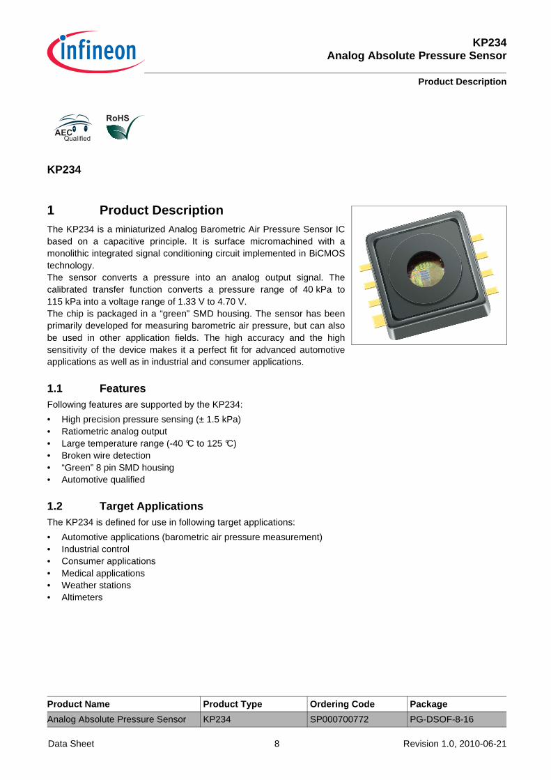
1 Product DescriptionThe KP234 is a miniaturized Analog Barometric Air Pressure Sensor ICbased on a capacitive principle. It is surface micromachined with amonolithic integrated signal conditioning circuit implemented in BiCMOStechnology.The sensor converts a pressure into an analog output signal. Thecalibrated transfer function converts a pressure range of 40 kPa to115 kPa into a voltage range of 1.33 V to 4.70 V.The chip is packaged in a “green” SMD housing. The sensor has beenprimarily developed for measuring barometric air pressure, but can alsobe used in other application fields. The high accuracy and the highsensitivity of the device makes it a perfect fit for advanced automotiveapplications as well as in industrial and consumer applications.
1.1 FeaturesFollowing features are supported by the KP234:
• High precision pressure sensing (± 1.5 kPa)• Ratiometric analog output• Large temperature range (-40 °C to 125 °C)• Broken wire detection• “Green” 8 pin SMD housing• Automotive qualified
1.2 Target ApplicationsThe KP234 is defined for use in following target applications:
• Automotive applications (barometric air pressure measurement)• Industrial control• Consumer applications• Medical applications• Weather stations• Altimeters
KP234Analog Absolute Pressure Sensor
Functional Description
Data Sheet 9 Revision 1.0, 2010-06-21
2 Functional DescriptionThe pressure is detected by an array of capacitive surface micromachined sensor cells. The sensor cell output isamplified, temperature compensated and linearized to obtain an output voltage that is proportional to the appliedpressure.The transfer function for linearization is computed in the digital part of the sensor using a third order polynomialcalculation. The transfer function is created from the following parameters:
• Minimum and maximum rated pressure• Voltage level at minimum and maximum rated pressure
The output is analog and ratiometric with respect to the supply voltage.All parameters needed for the complete calibration algorithm — such as offset, gain, temperature coefficients ofoffset and gain, and linearization parameters — are determined after assembly. The parameters are stored in anintegrated E²PROM. The E²PROM content is protected with forward error correction (a one bit error is detectedand corrected, errors of more than one bit are detected and the output signal is switched to ground potential).
Open Bond DetectionWhen the chip is not powered properly, the JFET transistors of the broken wire detection stage are self-conducting. For example, if the GND connection is interrupted, the output is drawn strongly to VDD. Similarly, ifthe VDD connection is broken, the output is drawn to GND.
KP234Analog Absolute Pressure Sensor
Functional Description
Data Sheet 10 Revision 1.0, 2010-06-21
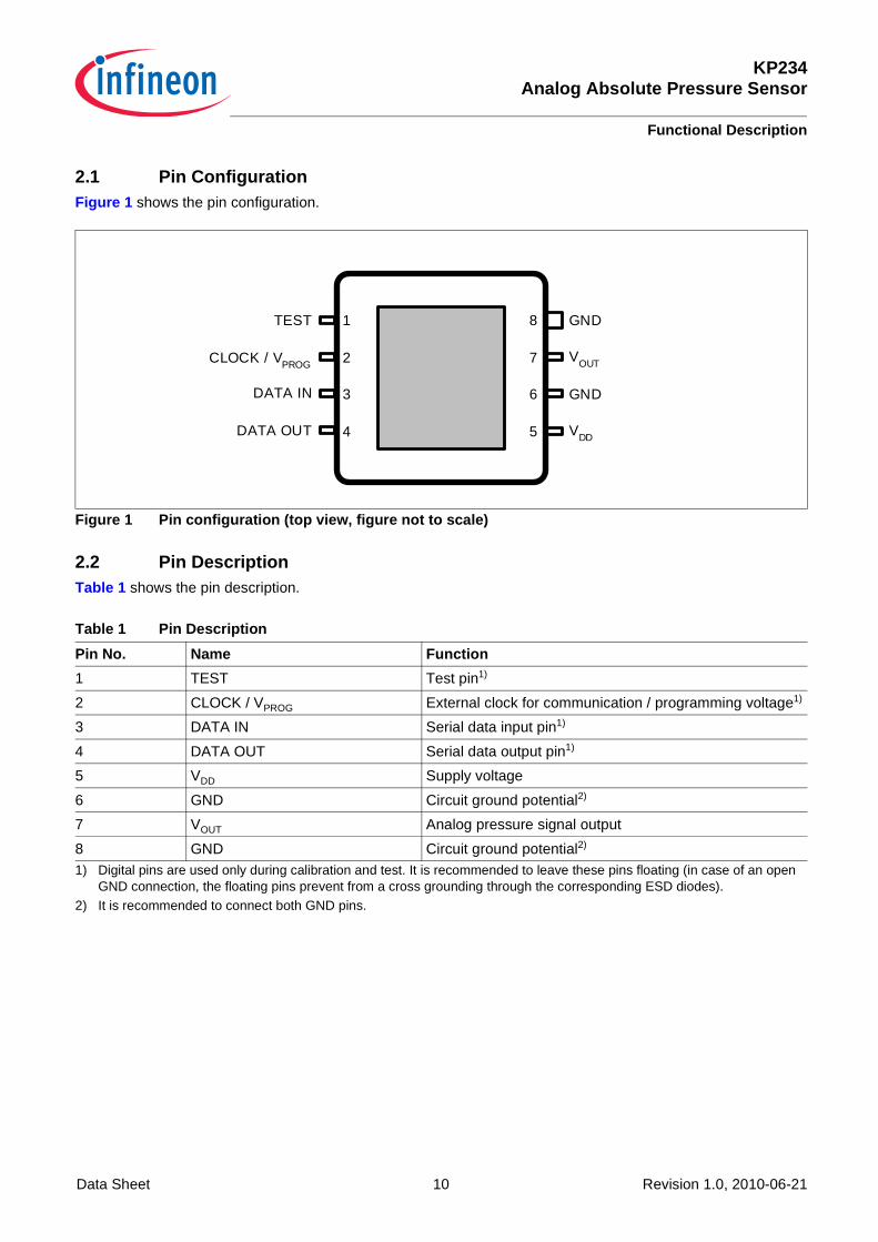
2.1 Pin ConfigurationFigure 1 shows the pin configuration.
Figure 1 Pin configuration (top view, figure not to s cale)
2.2 Pin DescriptionTable 1 shows the pin description.
Table 1 Pin Description
Pin No. Name Function
1 TEST Test pin1)
1) Digital pins are used only during calibration and test. It is recommended to leave these pins floating (in case of an open GND connection, the floating pins prevent from a cross grounding through the corresponding ESD diodes).
2 CLOCK / VPROG External clock for communication / programming voltage1)
3 DATA IN Serial data input pin1)
4 DATA OUT Serial data output pin1)
5 VDD Supply voltage
6 GND Circuit ground potential2)
2) It is recommended to connect both GND pins.
7 VOUT Analog pressure signal output
8 GND Circuit ground potential2)
1
2
3
4
8
7
6
5
GND
VOUT
GND
VDD
DATA IN
TEST
CLOCK / VPROG
DATA OUT
KP234Analog Absolute Pressure Sensor
Functional Description
Data Sheet 11 Revision 1.0, 2010-06-21
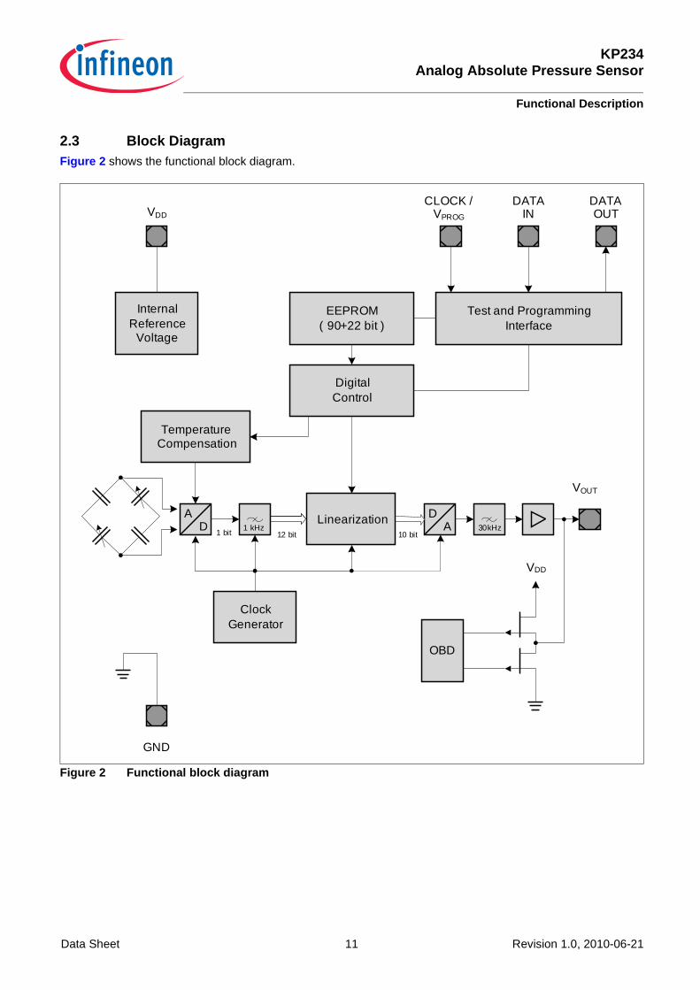
2.3 Block DiagramFigure 2 shows the functional block diagram.
Figure 2 Functional block diagram
AD
1 bit
DA
12 bit1 kHz
Linearization
OBD
VDD
ClockGenerator
TemperatureCompensation
InternalReference
Voltage
EEPROM( 90+22 bit )
DigitalControl
Test and ProgrammingInterface
VDD
CLOCK /VPROG
DATAIN
GND
DATAOUT
VOUT
30kHz10 bit
KP234Analog Absolute Pressure Sensor
Functional Description
Data Sheet 12 Revision 1.0, 2010-06-21
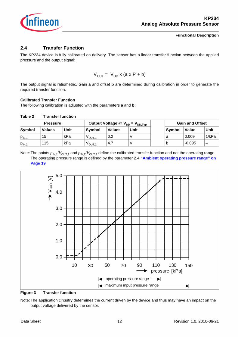
2.4 Transfer FunctionThe KP234 device is fully calibrated on delivery. The sensor has a linear transfer function between the appliedpressure and the output signal:
The output signal is ratiometric. Gain a and offset b are determined during calibration in order to generate therequired transfer function.
Calibrated Transfer FunctionThe following calibration is adjusted with the parameters a and b:
Note: The points pIN,1/VOUT,1 and pIN,2/VOUT,2 define the calibrated transfer function and not the operating range. The operating pressure range is defined by the parameter 2.4 “Ambient operating pressure range” on Page 19
Figure 3 Transfer function
Note: The application circuitry determines the current driven by the device and thus may have an impact on the output voltage delivered by the sensor.
Table 2 Transfer function
Pressure Output Voltage @ V DD = VDD,Typ Gain and Offset
Symbol Values Unit Symbol Values Unit Symbol Value Unit
pIN,1 15 kPa VOUT,1 0.2 V a 0.009 1/kPa
pIN,2 115 kPa VOUT,2 4.7 V b -0.095 –
VOUT = VDD x (a x P + b)
10
VO
UT
[V]
pressure [kPa]
0.0
1.0
3.0
2.0
4.0
5.0
30 50 70 90 110 130 150
operating pressure range
maximum input pressure range
KP234Analog Absolute Pressure Sensor
Functional Description
Data Sheet 13 Revision 1.0, 2010-06-21
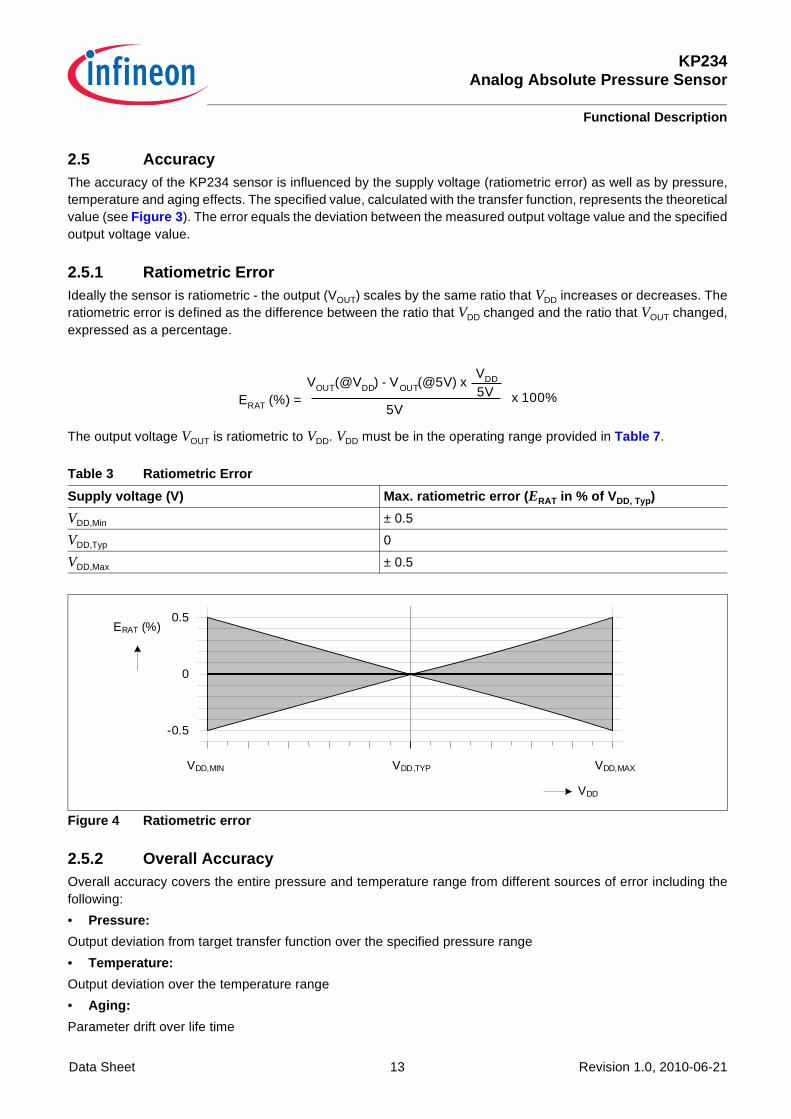
2.5 AccuracyThe accuracy of the KP234 sensor is influenced by the supply voltage (ratiometric error) as well as by pressure,temperature and aging effects. The specified value, calculated with the transfer function, represents the theoreticalvalue (see Figure 3 ). The error equals the deviation between the measured output voltage value and the specifiedoutput voltage value.
2.5.1 Ratiometric ErrorIdeally the sensor is ratiometric - the output (VOUT) scales by the same ratio that VDD increases or decreases. Theratiometric error is defined as the difference between the ratio that VDD changed and the ratio that VOUT changed,expressed as a percentage.
The output voltage VOUT is ratiometric to VDD. VDD must be in the operating range provided in Table 7 .
Figure 4 Ratiometric error
2.5.2 Overall AccuracyOverall accuracy covers the entire pressure and temperature range from different sources of error including thefollowing:
• Pressure:
Output deviation from target transfer function over the specified pressure range
• Temperature:
Output deviation over the temperature range
• Aging:
Parameter drift over life time
Table 3 Ratiometric Error
Supply voltage (V) Max. ratiometric error ( ERAT in % of V DD, Typ)
VDD,Min ± 0.5
VDD,Typ 0
VDD,Max ± 0.5
ERAT (%) =VOUT(@VDD) - VOUT(@5V) x
5V
VDD
5V x 100%
-0.5
0
VDD,MIN
VDD
0.5
VDD,MAXVDD,TYP
ERAT (%)
KP234Analog Absolute Pressure Sensor
Functional Description
Data Sheet 14 Revision 1.0, 2010-06-21
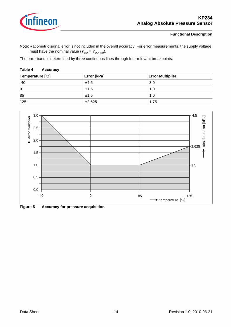
Note: Ratiometric signal error is not included in the overall accuracy. For error measurements, the supply voltage must have the nominal value (VDD = VDD,Typ).
The error band is determined by three continuous lines through four relevant breakpoints.
Figure 5 Accuracy for pressure acquisition
Table 4 Accuracy
Temperature [°C] Error [kPa] Error Multiplier
-40 ±4.5 3.0
0 ±1.5 1.0
85 ±1.5 1.0
125 ±2.625 1.75
-40 0 85 125
erro
r m
ultip
lier
temperature [°C]ab
solu
te e
rro
r [k
Pa
]
0.0
0.5
1.5
1.0
2.0
2.5
1.5
2.625
3.0 4.5
KP234Analog Absolute Pressure Sensor
Functional Description
Data Sheet 15 Revision 1.0, 2010-06-21
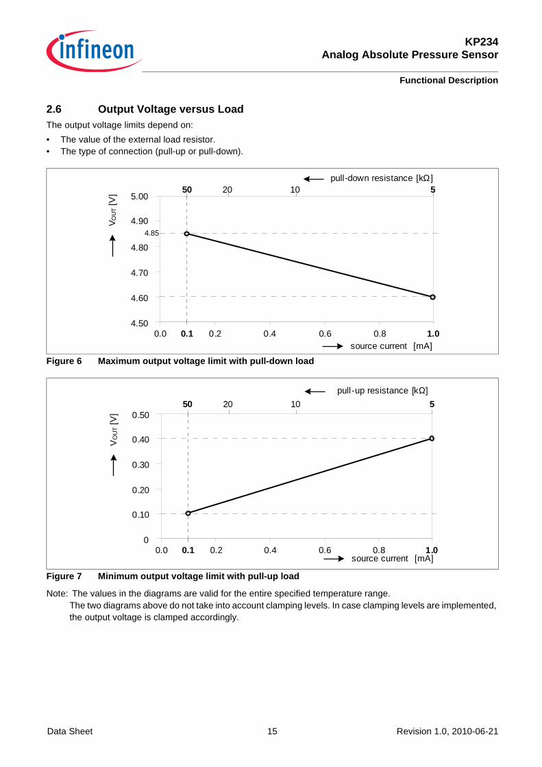
2.6 Output Voltage versus LoadThe output voltage limits depend on:
• The value of the external load resistor.• The type of connection (pull-up or pull-down).
Figure 6 Maximum output voltage limit with pull-down load
Figure 7 Minimum output voltage limit with pull-up lo ad
Note: The values in the diagrams are valid for the entire specified temperature range.The two diagrams above do not take into account clamping levels. In case clamping levels are implemented, the output voltage is clamped accordingly.
4.50
4.60
4.70
4.80
4.90
0.0 0.2 0.4 0.6 0.8 1.0source current [mA]
pull-down resistance [kΩ]20 10 550
0.1
4.85
VO
UT
[V] 5.00
0
0.10
0.20
0.30
0.40
0.50
0.0 0.2 0.4 0.6 0.8 1.0
20 10 550
0.1source current [mA]
pull-up resistance [kΩ]
VO
UT
[V]
KP234Analog Absolute Pressure Sensor
Functional Description
Data Sheet 16 Revision 1.0, 2010-06-21
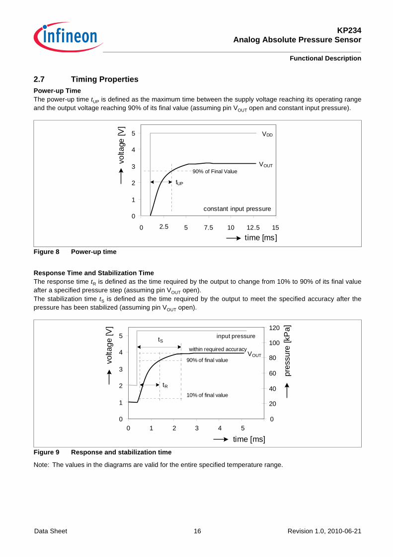
2.7 Timing PropertiesPower-up TimeThe power-up time tUP is defined as the maximum time between the supply voltage reaching its operating rangeand the output voltage reaching 90% of its final value (assuming pin VOUT open and constant input pressure).
Figure 8 Power-up time
Response Time and Stabilization TimeThe response time tR is defined as the time required by the output to change from 10% to 90% of its final valueafter a specified pressure step (assuming pin VOUT open).The stabilization time tS is defined as the time required by the output to meet the specified accuracy after thepressure has been stabilized (assuming pin VOUT open).
Figure 9 Response and stabilization time
Note: The values in the diagrams are valid for the entire specified temperature range.
0
1
2
3
4
5
0 2.5 5 7.5 10 12.5 15
time [ms]
VOUT90% of Final Value
VDD
tUP
volta
ge [V
]
constant input pressure
0
1
2
3
4
5
0 2
time [ms]
volta
ge [V
]
0
20
40
60
80
100
120
pres
sure
[kP
a]
VOUT90% of final value
input pressure
tR10% of final value
tSwithin required accuracy
1 3 4 5
KP234Analog Absolute Pressure Sensor
Specification
Data Sheet 17 Revision 1.0, 2010-06-21
3 Specification
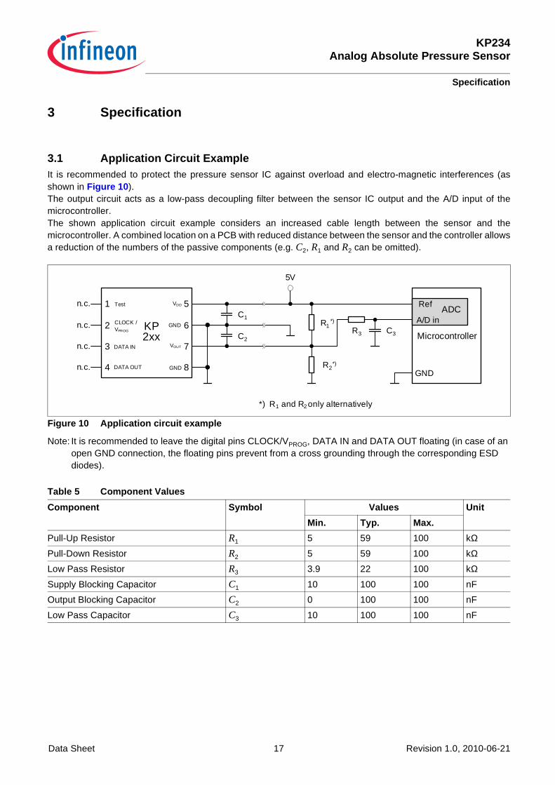
3.1 Application Circuit ExampleIt is recommended to protect the pressure sensor IC against overload and electro-magnetic interferences (as shown in Figure 10 ). The output circuit acts as a low-pass decoupling filter between the sensor IC output and the A/D input of the microcontroller. The shown application circuit example considers an increased cable length between the sensor and the microcontroller. A combined location on a PCB with reduced distance between the sensor and the controller allows a reduction of the numbers of the passive components (e.g. C2, R1 and R2 can be omitted).
Figure 10 Application circuit example
Note: It is recommended to leave the digital pins CLOCK/VPROG, DATA IN and DATA OUT floating (in case of an open GND connection, the floating pins prevent from a cross grounding through the corresponding ESD diodes).
Table 5 Component Values
Component Symbol Values Unit
Min. Typ. Max.
Pull-Up Resistor R1 5 59 100 kΩ
Pull-Down Resistor R2 5 59 100 kΩ
Low Pass Resistor R3 3.9 22 100 kΩ
Supply Blocking Capacitor C1 10 100 100 nF
Output Blocking Capacitor C2 0 100 100 nF
Low Pass Capacitor C3 10 100 100 nF
Microcontroller
ADCRef
A/D in
GND
5V
C1
C2
R1
R2
R3 C3
*)
*)
*) R1 and R2 only alternatively
KP2xx
4 DATA OUT
3 DATA IN
2 CLOCK / VPROG
1 Test VDD 5
GND 6
VOUT 7
GND 8
n.c.
n.c.
n.c.
n.c.
KP234Analog Absolute Pressure Sensor
Specification
Data Sheet 18 Revision 1.0, 2010-06-21
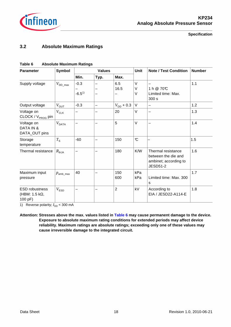
3.2 Absolute Maximum Ratings
Attention: Stresses above the max. values listed in Table 6 may cause permanent damage to the device. Exposure to absolute maximum rating conditions for extended periods may affect device reliability. Maximum ratings are absolute ratings; exceeding only one of these values may cause irreversible damage to the integrated circuit .
Table 6 Absolute Maximum Ratings
Parameter Symbol Values Unit Note / Test Condition Numbe r
Min. Typ. Max.
Supply voltage VDD_max -0.3 – -6.51)
1) Reverse polarity; IDD < 300 mA
– – –
6.5 16.5 –
V V V
– 1 h @ 70°C Limited time: Max. 300 s
1.1
Output voltage VOUT -0.3 – VDD + 0.3 V – 1.2
Voltage on CLOCK / VPROG pin
VCLK – – 20 V – 1.3
Voltage on DATA IN & DATA_OUT pins
VDATA – – 5 V – 1.4
Storage temperature
TS -60 – 150 °C – 1.5
Thermal resistance RthJA – – 180 K/W Thermal resistance between the die and ambinet; according to JESD51-2
1.6
Maximum input pressure
pamb_max 40 – 150 600
kPa kPa
Limited time: Max. 300 s
1.7
ESD robustness (HBM: 1.5 kΩ, 100 pF)
VESD – – 2 kV According to EIA / JESD22-A114-E
1.8
KP234Analog Absolute Pressure Sensor
Specification
Data Sheet 19 Revision 1.0, 2010-06-21
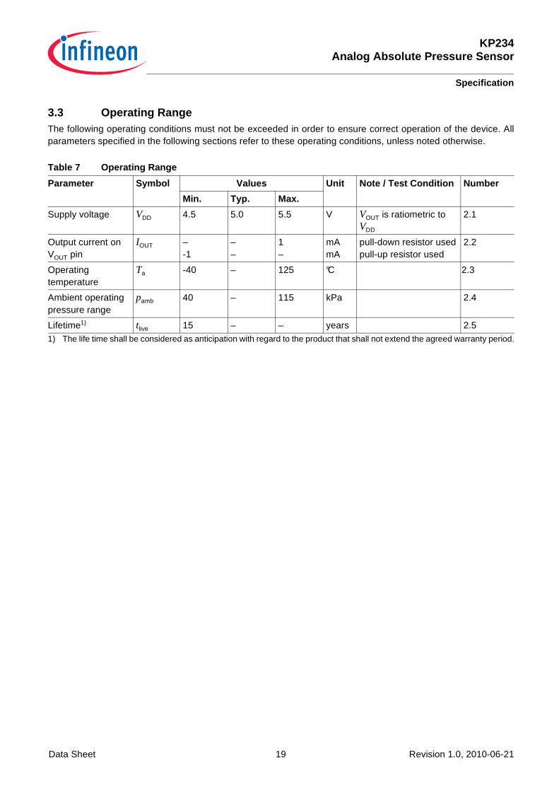
3.3 Operating RangeThe following operating conditions must not be exceeded in order to ensure correct operation of the device. All parameters specified in the following sections refer to these operating conditions, unless noted otherwise.
Table 7 Operating Range
Parameter Symbol Values Unit Note / Test Condition Numbe r
Min. Typ. Max.
Supply voltage VDD 4.5 5.0 5.5 V VOUT is ratiometric to VDD
2.1
Output current on VOUT pin
IOUT – -1
– –
1 –
mA mA
pull-down resistor used pull-up resistor used
2.2
Operating temperature
Ta -40 – 125 °C 2.3
Ambient operating pressure range
pamb 40 – 115 kPa 2.4
Lifetime1)
1) The life time shall be considered as anticipation with regard to the product that shall not extend the agreed warranty period.
tlive 15 – – years 2.5
KP234Analog Absolute Pressure Sensor
Specification
Data Sheet 20 Revision 1.0, 2010-06-21
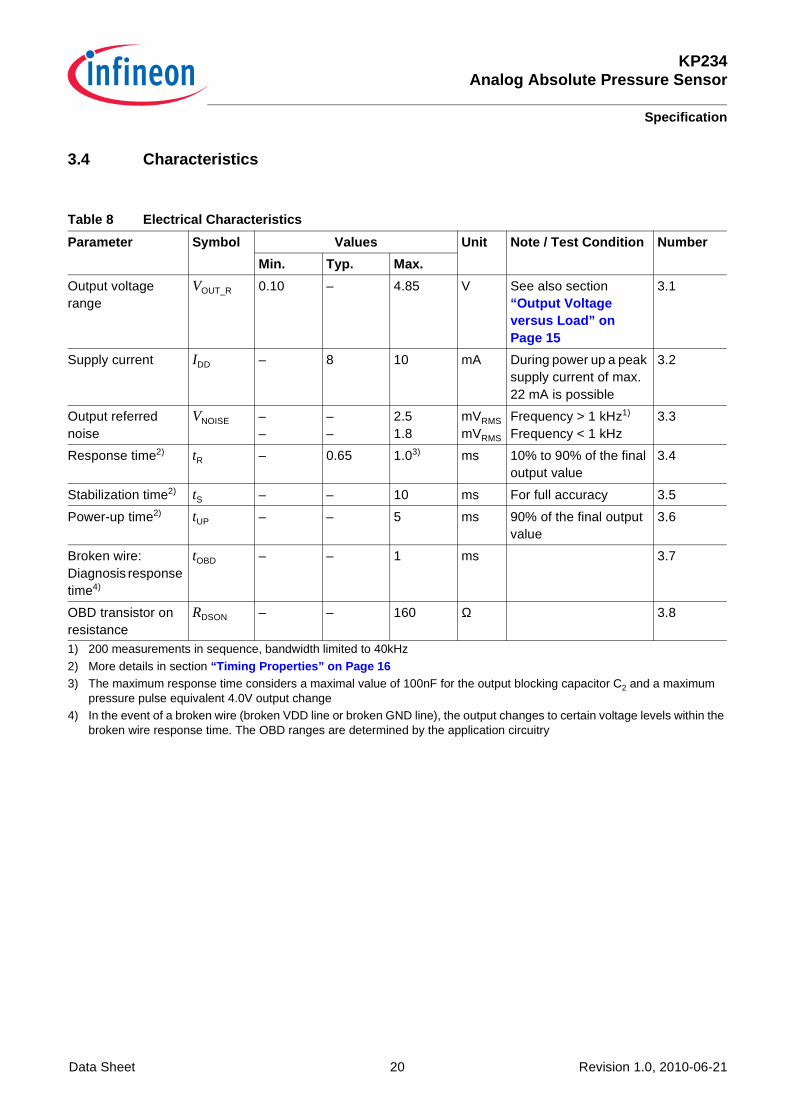
3.4 Characteristics
Table 8 Electrical Characteristics
Parameter Symbol Values Unit Note / Test Condition Numbe r
Min. Typ. Max.
Output voltage range
VOUT_R 0.10 – 4.85 V See also section “Output Voltage versus Load” on Page 15
3.1
Supply current IDD – 8 10 mA During power up a peak supply current of max. 22 mA is possible
3.2
Output referred noise
VNOISE – –
– –
2.5 1.8
mVRMS mVRMS
Frequency > 1 kHz1) Frequency < 1 kHz
1) 200 measurements in sequence, bandwidth limited to 40kHz
3.3
Response time2)
2) More details in section “Timing Properties” on Page 16
tR – 0.65 1.03)
3) The maximum response time considers a maximal value of 100nF for the output blocking capacitor C2 and a maximum pressure pulse equivalent 4.0V output change
ms 10% to 90% of the final output value
3.4
Stabilization time2) tS – – 10 ms For full accuracy 3.5
Power-up time2) tUP – – 5 ms 90% of the final output value
3.6
Broken wire: Diagnosis response time4)
4) In the event of a broken wire (broken VDD line or broken GND line), the output changes to certain voltage levels within the broken wire response time. The OBD ranges are determined by the application circuitry
tOBD – – 1 ms 3.7
OBD transistor on resistance
RDSON – – 160 Ω 3.8
KP234Analog Absolute Pressure Sensor
Specification
Data Sheet 21 Revision 1.0, 2010-06-21
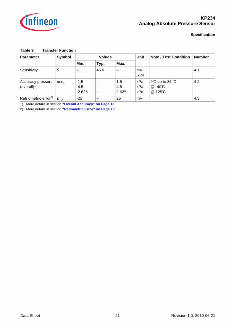
Table 9 Transfer Function
Parameter Symbol Values Unit Note / Test Condition Numbe r
Min. Typ. Max.
Sensitivity S – 45.0 – mV /kPa
4.1
Accuracy pressure (overall)1)
1) More details in section “Overall Accuracy” on Page 13
accp -1.5 -4.5 -2.625
– – –
1.5 4.5 2.625
kPa kPa kPa
0°C up to 85 °C @ -40°C @ 125°C
4.2
Ratriometric error2)
2) More details in section “Ratiometric Error” on Page 13
ERAT -25 – 25 mV 4.3
KP234Analog Absolute Pressure Sensor
Package Information
Data Sheet 22 Revision 1.0, 2010-06-21
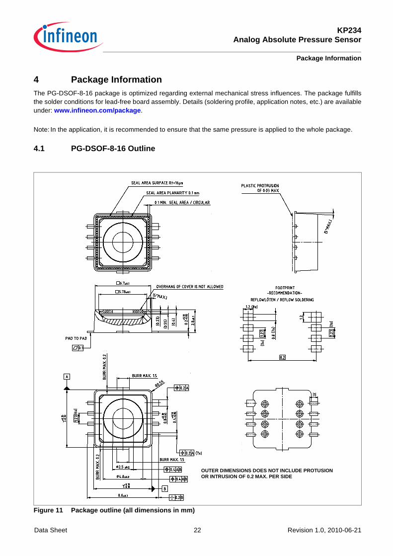
4 Package InformationThe PG-DSOF-8-16 package is optimized regarding external mechanical stress influences. The package fulfillsthe solder conditions for lead-free board assembly. Details (soldering profile, application notes, etc.) are availableunder: www.infineon.com/package .
Note: In the application, it is recommended to ensure that the same pressure is applied to the whole package.
4.1 PG-DSOF-8-16 Outline
Figure 11 Package outline (all dimensions in mm)
OUTER DIMENSIONS DOES NOT INCLUDE PROTUSION OR INTRUSION OF 0.2 MAX. PER SIDE
KP234Analog Absolute Pressure Sensor
Package Information
Data Sheet 23 Revision 1.0, 2010-06-21
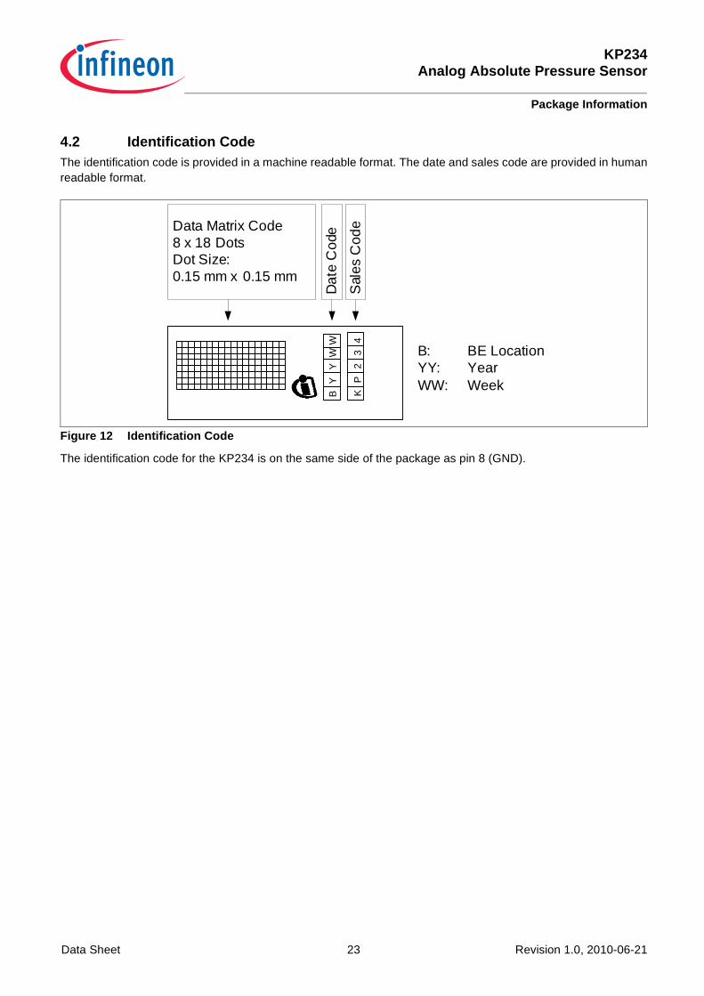
4.2 Identification CodeThe identification code is provided in a machine readable format. The date and sales code are provided in humanreadable format.
Figure 12 Identification Code
The identification code for the KP234 is on the same side of the package as pin 8 (GND).
Data Matrix Code8 x 18 DotsDot Size:0.15 mm x 0.15 mm
Dat
e C
ode
Sal
es C
ode
BY
YW
KP
23
4W
B: BE LocationYY: YearWW: Week

KP234Analog Absolute Pressure Sensor
Data Sheet 24 Revision 1.0, 2010-06-21