Embed Size (px)
Citation preview

An integration centric approach for the
coordination of distributed software
development projects
Lars Taxén
Linköping University Post Print
N.B.: When citing this work, cite the original article.
Original Publication:
Lars Taxén , An integration centric approach for the coordination of distributed software
development projects, 2006, Information and Software Technology, (48), 9, 767-780.
http://dx.doi.org/10.1016/j.infsof.2006.01.007
Copyright: Elsevier
http://www.elsevier.com/
Postprint available at: Linköping University Electronic Press
http://urn.kb.se/resolve?urn=urn:nbn:se:liu:diva-50135

1
An Integrated Centric Approach for the Coordination of Distributed SW-projects
Lars Taxén
Campus Norrköping, Linköping University
Department of Science and Technology
Norrköping, Sweden
Postal address: Rundan 91, 14645 Tullinge, Sweden, Phone: +46 730977864
Abstract
This paper presents an approach for Distributed Software Development (DSD) that is based on
two fundaments. The first one is an integration centric engineering process, which aims at
managing technical and social dependencies in DSD projects. The second fundament is a
strategy for operationalizing the coordination of the engineering process. The purpose of this
strategy is to provide global information system support for coordination and, simultaneously
achieve a shared meaning about what should be coordinated and how. The approach has been
successfully used at Ericsson, a major supplier of telecommunication systems worldwide. We
discuss the effects of applying the approach in the coordination of extraordinary complex
projects developing nodes in the 3rd
generation of mobile systems. Although many obstacles
have to be addressed, the results show that the approach is a viable way to manage DSD dur-
ing very demanding circumstances.
Keywords: distributed SW development, integration centric engineering, coordination, shared meaning,
flexible IS/ IT support, telecom systems
1 Introduction
The interest in distributed software development1 (DSD) has increased due to factors
such as reduced costs, the access to well-educated labor pools, the possibility of 24
hour development, global presence and proximity to customers (e.g. [6], [9], [12],
[16], [17], [20], [26], [28], [29], [31]). The distribution, which may take place inside
or across organizations, does not necessarily have to be global. However, many chal-
lenges already present in centralized SW development are aggravated by the distribu-
tion. At the core of these challenges lies the issue of coordination. “While there is no
single cause of the software crisis, a major contributor is the problem of coordinating
activities while developing large software systems.” ([21], p. 69).
Some of the challenges that need increased attention in DSD are:
Architectural design
The architecture of the SW system should be designed in such a way that DSD is
facilitated. It should be easy to identify development tasks that with low interaction.
Furthermore, the architecture should be transparent in the sense that it can be easily
communicated across the entire project [6], [28].
1 This type of development has also been named Global Software Development [9] and Off-
shore development [31].

2
Software Engineering Process
By this, we mean total set of software engineering activities needed to transform user
requirements into software [19]. DSD makes the management of dependencies be-
tween these activities more difficult.
Software Development Model
DSD implies that the software development model must be carefully chosen. Sak-
thivel [31] has shown that there is a complex relationship between the potential for
distribution and the type of development process (spiral, waterfall, Rapid Application
Development, Agile Development Method, etc.).
Project management
The distribution of the development task brings about more demanding requirements
on project management. When people cannot meet face to face, the burden of coordi-
nation and communication increases. The geographical separation means that effort
estimations, project planning and control become more difficult. The need for a
common understanding of project goals, plans and progress increases in DSD. In
addition, the management of issues like trust, responsibilities, commitments, incite-
ments, etc., is aggravated in DSD.
Multiculturalism
DSD implies an increased attention to cultural differences. A subtle balance must be
struck between enforcing mandatory regulations imposed by coordination and local
autonomy concerning development methods, support tools, etc. Going to either ex-
treme will lead to problems. Enforcing a common development process on all sites
will most likely arouse resistance and cause conflicts [14]. On the other hand, allow-
ing full freedom for each site to control the development will make coordination
across sites impossible.
IS / IT support
DSD puts higher requirements on the IS / IT support. The infrastructure in distant
sites may be inadequate, which may cause problems with information system (IS)
performance and stability. In addition, there is a need for a common project repository
where requirements, engineering change orders, system builds, etc., can be globally
available. This means that the IS architectures must be carefully designed with respect
to what roles ISs should have and how they should interact.
In this paper, we will discuss how Ericsson, a major supplier of telecommunica-
tion systems worldwide, is facing the challenges associated with DSD in their devel-
opment practice. The ensemble of telecommunication systems has been called the
world’s largest machine. It consists of networks of interacting nodes, each of which
performs some kind of utility in the network like keeping track of the position of a
cellular phone, providing charging functions, supplying data about the phone owner,
etc. (see Figure 1).

3
Figure 1: The principal structure of a telecommunication system
A telecom system is a truly complex system in several ways. The system is continu-
ously evolving. Many different technologies are utilized such as radio, software,
hardware, optical, mechanical, etc. There are very strict requirements on real-time
access and system downtime. Furthermore, modern communication standards such as
GSM (Global System for Mobile Communications) must be compliant with older
ones.
In the telecommunications market there is a fierce competition among systems
providers like Ericsson, Nokia and others. Moreover, this market is changing rapidly.
Therefore, the suppliers have to be more reactive and flexible to the market needs.
This in turn prompts frequent re-organizations, including company outsourcing and
new partnership constellations.
In addition to these circumstances, the development task is inherently complex.
The sheer size of the task is enormous. A project developing nodes in the 3rd
genera-
tion of mobile systems may take more than a year to execute and involve several
thousand actors all over the world. The number of software code lines in some nodes
may be in the order of millions. During the development, the outcomes of several
hundreds of development steps must be coordinated, verified and integrated in a pre-
cise and timely manner. Furthermore, since there are a number of different technolo-
gies involved, very heterogeneous skills are needed.
The development is in general carried out at many different sites worldwide.
These sites usually have some autonomy to structure their own way of working. As a
result, the coordination of such projects must deal with a multitude of technical, mar-
ket related and organizational interdependencies. Most often, this requires mutual
adjustment across many types of both technical and organizational boundaries [1].
In summary, the development of a telecom system can be seen as a paradigmatic
example of the challenges involved in DSD. The approach Ericsson has taken to ad-
dress these challenges is based on two fundaments. The first one is an integration
centric engineering process, which aims at managing technical and social dependen-
cies in DSD projects. The second fundament is a strategy for operationalizing the
4
coordination of the engineering process. The purpose of this strategy is to provide
global IS support for coordination and, simultaneously achieve a shared meaning
about what should be coordinated and how. In this paper, we will refer to the Ericsson
way as the ICD (Integration Centric Development) approach.
The paper is organized as follows: In the next section, we give a brief account of
the research design. In Section 3.1, we describe the engineering process. The core of
this process is a construct called the “anatomy”, which is an illustration – preferably
on one page – of the functional dependencies in the system. The anatomy is the basis
for building the total functionality of the SW-system is in steps – increments – that
are consecutively verified and integrated from basic functionality to an operational
system. The gist of process is to identify and manage critical dependencies in the
development task, regardless of whether these are of a technical or social nature. The-
oretical and practical aspects of the anatomy driven engineering process are treated in
[23] and [35].
In Section 3.2 we outline how the engineering process is coordinated. This con-
cerns various management activates such as project management, requirement man-
agement, engineering change order management, baseline and milestone manage-
ment, test management, system build management, etc. The central idea is that actors
involved in these management tasks together define how these phenomena should be
apprehended and how the corresponding IS / IT support shall be implemented. In the
following section we report on some effects from applying the approach in the Erics-
son development practice. Finally, we discuss the results and draw some conclusions.
The paper is limited to the engineering and coordinating aspects of DSD. This
means that we do not discuss the software development model. Moreover, even if we
focus on SW development in this paper, the ICD approach is equally applicable if
some functionality is provided by hardware.
2 Research design
The research results are derived form mainly two sources. The first source is experi-
ences from the author’s professional work at Ericsson. This concerns both theoretical
and practical result achieved between roughly 1990 and 2003 [33]. The second source
is a study of the use of the anatomy at one development unit at Ericsson, reported in
[23]. The data sources are interviews, Ericsson internal documents, meeting notes,
etc. (for details, see [33] and [23]). Thus, the empirical data is a mixture of personal
experiences from many projects and a deeper study of one particular project.
In general, the research can be characterized as exploratory in nature and based
on longitudinal case studies. The use of qualitative methods such as case studies is
appropriate in studying human action in real life situations, especially those ones in
which practice precedes theory[37]. Moreover, the research can, at least in part, be
classified as action research [5] since the author has been actively promoting the IS /
IT support for the ICD approach at Ericsson.
3 The Integration Centric approach
In this section, we will describe the two fundaments of the ICD approach. In Section
3.1 we outline the engineering process and in Section 3.2 the strategy for operational-
izing the coordination of the engineering process.
5
3.1 The engineering process
The engineering process is based on a construct called the “anatomy”. The anatomy is
an illustration, which shows functional dependencies in the system from start-up to an
operational system ([3], [23], [35]). The central idea behind using the anatomy in
system development is to design and test the system in the same order as it “comes
alive”. In order to achieve this, the engineering process is executed in three steps:
anatomy definition, increment planning and integration planning. These steps are not
sharply separated; rather they should be seen as different foci in the coordination of
the development task. In the following sections, we will describe the principles of the
engineering process using a simplified example from the Ericsson practice: the devel-
opment of a processor in a telecom system.
3.1.1 Anatomy Definition
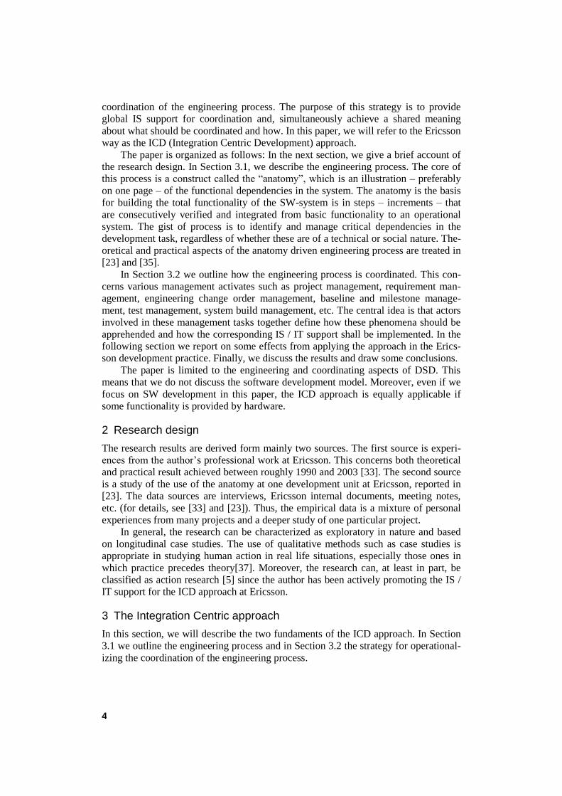
The purpose of the anatomy definition step is to achieve a shared meaning about how
the system works in terms of functional dependencies. In Figure 2, the anatomy of the
processor is shown. It is outside the scope of this paper to describe the working of the
processor in detail. However, the name designations should indicate the character of
the functions.
Power On
Clock MAI
Reset SPU
Reset MAI
Reset IPUFan Control
I-Test IPU
Test Access
I-Test SPU
Reset RPH
Start of RPs
Routine Tests
I-Test RPH
Traffic
RP: Regional Processor
RPH: Regional Processor Handler SPU: Signal Processor UnitIPU: Instruction Processor Unit
MAI: Maintenance Unit
Figure 2: The anatomy of a processor in a telecom system
The anatomy is created in several meetings where the mindset should be: “if you
‘power-on’ what happen then and then.” This question is repeated until you reach the
end functionality. Thus, the approach is in essence a bottom-up process rather than
top-down [3]. When deciding which functions to include, the focus should be on inte-
gration and testability since this will be used to plan and monitor the project.
It can be noted that the anatomy shown in Figure 2, is to a certain extent arbi-
trary. Other functionalities might have been included and the level of detail is more or
less arbitrary. This indicates that the anatomy is, as indeed any other model, some-
thing that the actors must agree upon. Therefore, it usually takes several meeting be-
fore a working consensus is achieved.

6
3.1.2 Increment planning
In the second step, the implementation of the system is defined. The functions are
grouped into integration steps — increments — in such a way that the resulting func-
tionality after each added increment can be verified. Thus, the dependencies in focus
in this step are increment dependencies. The intention is to parallelize design and
testing as much as possible. The increment plan describes in what order increments
need to be completed to ensure smooth progress. The structure of the plan is deter-
mined by a number of circumstances such as available resources, customer feedback,
complicated or simple functions, geographical proximity between resources, func-
tions that can be tested jointly, etc. [3]. In Figure 3, a possible increment plan of the
processor is shown.
Power On
Clock MAI
Reset SPU
Reset MAI
Reset IPUFan Control
I-Test IPU
Test Access
I-Test SPU
Reset RPH
Start of RPs
Routine Tests
I-Test RPH
Traffic
Increment 1
Increment 3
Increment 2
Increment 5
Increment 6
Increment 4
Figure 3: Increment plan of the processor.
3.1.3 Integration planning
In the third step, the purpose is to divide the work between subprojects and establish a
shared commitment about what is delivered, from whom and when. This means that
resources are assigned and dates for deliveries of the increments are negotiated. For
each increment, traditional time and resource plans are made as well. The integration
plan focuses on the dependencies between subprojects. It clearly shows the impact of
delaying a certain delivery. Thus, it provides early warnings of delays, which give the
project management time to take corrective actions. During the project, the integra-
tion plan is used as an instrument for controlling the progress of the project. The state
of each increment is visualized by traffic-light cues such as Green – On Plan, Yellow
– Warning, Red – Off Track, etc.

7
In Figure 4, an integration plan of the processor is shown.
Test Access Reset RPHReset MAI
I-Test IPU
I-Test SPU
Start of RPs
Project A-1, April 15
Project A-2, April 30
Project B-1, May 17
Project C-1, May 30
Project A-3, B-3, C-2, June 15
Project B-2, May 15
Increment 1
Increment 3
Increment 2
Increment 5
Increment 6Increment 4
Figure 4: Integration plan of the processor
It can be seen that the increments are assigned to various subprojects depending on
specific competences needed. For example, both increments 3 and 5 concern testing.
Those increments are assigned to subprojects B-1 and B-2, indicting that both subpro-
jects are run within sites that are knowledgeable in testing.
3.2 Operationalizing coordination
Co-ordination is a nebulous concept that has been defined in various ways (e.g. [22],
[24], [27]). In the ICD approach, the definition of coordination departs from the defi-
nition given by Malone & Crowston:
“Co-ordination is managing dependencies between activities” ([24], p. 90)
In order to operationalize this definition Taxén has suggested regarding coordination
from a workpractice point of view ([33]). In a workpractice, actors come together in
order to produce a certain result that other actors need ([15], [32]). Such a workprac-
tice may be, for example, a development practice at Ericsson. In this practice, actors
are performing various tasks. Some of these tasks have an explicit goal of coordinat-
ing the development. By regarding the workpractice from a coordination point of
view, we can emphasize only those phenomena that are relevant for coordination. We
will refer to this perspective of the workpractice as the coordination domain. This
means that a certain item, say a requirement, will be apprehended differently depend-
ing on the perspective of the workpractice. From a development point of view, the
understanding of the content of the requirement is in focus. From a coordination point
of view, its status, revision and relation to other items are in focus.
It is outside the scope of this paper to give a detailed account for this line of rea-
soning (see [33] and [34]). The gist of the reasoning is that the actors in the coordina-
tion domain have to construct the domain in order to operationalize coordination. In
order to do so, they work with mainly two instruments: a context model and an IS.
The context model shows what items the actors consider important for coordination
8
and how these are related to each other (see e.g. Figure 6). By continually iterating
between modifying the context model, implementing it in the IS and evaluating the
result, coordination is gradually constructed in terms of significant items (displayed in
the context model), IS support and a shared meaning among the actors about what
constitutes coordination. We will call this procedure the Domain Construction Strate-
gy [33]. The motivation behind this seemingly awkward procedure is that the problem
of achieving a shared meaning has turned out to be a major obstacle in DSD (e.g. [6],
[17], [26], [28], [29], [31]).
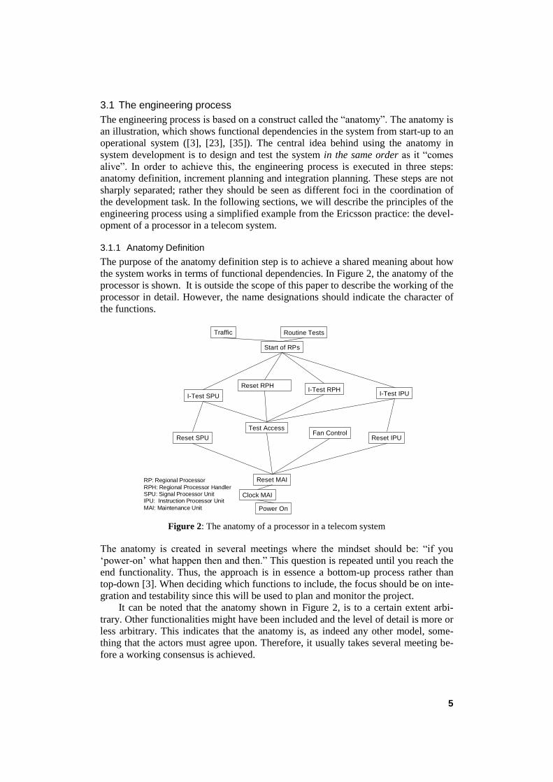
The construction of the coordination domain is carried out in three phases: elabo-
ration, trust boosting and expansion (see Figure 5). In the first two phases, the focus
is on establishing the coordination domain as a bridgehead in one project before ex-
panding it to other projects in the third phase. This means that the gist of the strategy
is the quick establishment a relatively stable core of shared meaning in a small group
of actors, which is then propagated to other actors in an ongoing domain construction
process.
elaboration
Shared meaning• “seed” domain
• heavy interaction
• “daily build”
• prototyping
• small teams
• one main user
• no boards interference
• risk capital financing
trust boosting
Sharp usage• one project
• controlled changes
• fine tuning
• all user roles involved
• data entry securing
• immediate personal support
• reference group
• financing per project
expansion
Full activity domain roll-out• several projects
• controlled changes
• fine tuning
• all user roles involved
• data entry securing
• regular support
• reference group
• line financing
Semiosis - shared meaning
Time
Figure 5. The domain construction strategy
3.2.1 Elaboration
In this phase, the initial construction of the domain is carried out. The main purpose is
to achieve a tentative consensus about the content and structure of the domain. The
work is carried out in a ‘daily build’ manner in close interaction among the actors.
The work is financed on a risk capital basis. Detailed return on investment analysis is
not required since the reliability of such analysis will be low. The following tasks are
carried out in this phase:
State the coordination requirements on an overall level, for example, “There shall
be support for engineering change order management, requirement management
(RM) and ICD based software development”. These different areas within the
coordination domain are called coordination areas.
Define a “task force” for each coordination area. For example, for RM this force
may consist of a project manager, a requirement manager and an IS specialist.

9
Define a first version of the context model is terms of relevant phenomena and
how these are related to each other. Established methods may be used as a point
of departure. Define attributes, cardinalities, revision stepping rules, state sets,
etc. In Figure 3, an example from Ericsson of a context model is shown.
CustomerCustomer
FeatureSet of Requirements
System
Issue
AD
Package
Tech. Feature
Inc Spec
Feature
Increment
Impact
Increment
Task SpecInc. MS
Project
AD Task AD MS
Increment
Responsible
Resource
Design
Item
Functional
Anatomy
Function
Design
Base
Product Document
Individual
Team-leader
LDC
Subproject mgr
Project manager
Implementation
Specification
Implementation
Proposal
Functional
Framework
Project MS
Figure 6: An example of context model in the Ericsson practice (1997).
Implement the context model in the IS. Instantiate object of the types, for exam-
ple, a number of requirements and requirement issuers, and relate them to each
other. Create reports. Evaluate the information: What is missing? Is this correct?
Etc. In Figure 7, an example of this kind of information, corresponding to the
context model in Figure 6 is shown.
Figure 7: An example of requirements tracing from customer to system elements (1997)

10
Make changes to the context model and implement these anew. Continue in this
manner until the actors agree that the constructed domain is useful.
3.2.2 Trust boosting
The purpose of this phase is to boost the trust about the feasibility of the domain as
constructed in the elaboration phase. Key issues are getting all actors in the project to
trust the data in the IS and make sure that the performance of the IS is acceptable at
all units worldwide. This is done in one sharp project, that is, a project that develops a
product for some client. The task force is still driving the construction. All user roles
around the project are involved, and immediate, personalized support is provided. The
development of the domain progresses by controlled changes and consists of fine
tuning steps. No major reconstruction of the domain is allowed. Reference groups and
steering boards are consulted and the financing is done on a project basis. The follow-
ing tasks are carried out in this phase:
Transfer data from previous sources into the IS. For example, requirements pre-
viously kept as text in requirement specification documents are translated into
requirement objects, which can be individually managed and related to other
items according to the context model.
Set a date when the project shall start using the data in the IS as their primary
source for planning and monitoring the project. The reason for this is that the da-
ta otherwise may be inconsistent.
Take measures to make the actors use the IS, i.e. enter data into and retrieve data
from the IS. This can be done by requiring that the only source for progress re-
ports is the data in the IS.
Keep a list of issues that need to be attended. Any such issue needs to be agreed
upon by the task force before it is implemented in the IS.
3.2.3 Expansion
In this phase, several projects are involved. As in the trust-boosting phase, the con-
struction is done by controlled changes, however now in a formalized way. The fi-
nancing is done by the line organization in order to keep the domain intact between
projects. The following tasks are carried out in this phase:
Changes in the models must be agreed upon by a change control board before it
is implemented in the IS. This means that an incoming issue is sent out to an
analysis group where its impact is estimated in terms of cost and implementation
effort. A formal decision to go ahead is taken and the issue is followed up until it
is fully implemented.
If the domain has to cooperate with other domains, a work must be initialized to
coordinate these domains. When doing so, a balance must be struck between
what is necessary to coordinate and what can be left to each individual domain to
decide independently.
11
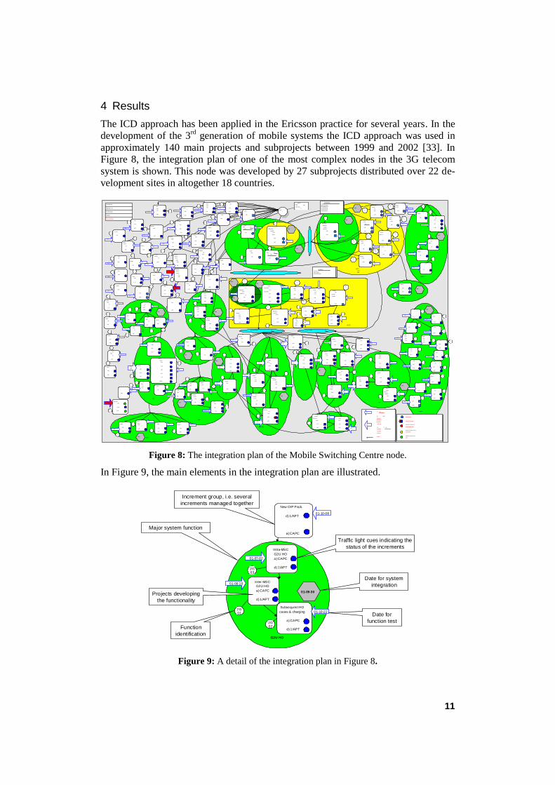
4 Results
The ICD approach has been applied in the Ericsson practice for several years. In the
development of the 3rd
generation of mobile systems the ICD approach was used in
approximately 140 main projects and subprojects between 1999 and 2002 [33]. In
Figure 8, the integration plan of one of the most complex nodes in the 3G telecom
system is shown. This node was developed by 27 subprojects distributed over 22 de-
velopment sites in altogether 18 countries.
C7 f uncti ons
CAMEL Ph3 / IN
A
X
E
M
G
W
T
r
a
c
k
GCP TRACK
Desi gn Base
1.5
GPRS+SM S
f) GDBSMS
a) CAPC
d) 1/ APT
f) GDB
MAP SCCP
Segmentation
a) CAPC
d) 1/ APT
Tit le: AXE Anat omy for 2. 0
2/0062-FCPW 101 50 PA51
Edit or: EED/ X/D St ef an Berg
Date: 2002- 04- 11
PRA-Dat e: 2001-11-15( RFA 28. 02.)
01- 10- 22
01- 10- 08
01- 10- 08
2E
01
2E
02
Dependency
2J
01
Basi c Cal l
wit h AXE
01- 10- 15
01- 10- 30
APG40 / APZ11. 1
Desi gn base on
f uncti onal level , not
necessari ly on pr oduct
level
01- 11- 15
new CSD
H.324
fall back
d) 1/ APT
2U
01
2U
02
01- 06- 18hal fr at e
r emoval
d) 1/ APT
01- 09- 20
GT Mod. f or
Connect ion
less tr af fic
a) CAPC
01- 09- 10
2J
04
Announcement
changes
a) CAPC
b) CNCP01- 09- 10
2DA
03
Advanced call
cases wit h
AXE/Cello
BICC dr op 2
com pl . basi c
cal l
a) CAPC
01- 07- 16BICC dr op 3
SS
a) CAPC
2DA
05
new HW
li ft SMAC into 2.0
( incl . drop 2)
a) CAPC
b) CNCP
c) CSPP
d) 1/ APT
f) GDB
h) SM AC par t
2S
06
01- 10- 22
GPRS
char gi ng
char acteri st ics
f) GDB
01- 10- 08
2E
04
RONASSSP
a) CAPC
01- 10- 08
2E
05
ATI
g) SCP- T
01- 09- 10
2E
06
Cause of no
CLI
a) CAPC
d) 1/ APT2F
16
01- 07- 30
U2G HO
for CSD
a) CAPC
d) 1/ APT
2F
13
01- 10- 08
SS
U2G HO + SRNS Relo.
R- TDM
CSD
IN
BICC ++
- MGW vali dati on
- AXE- Cello
inter wor k
a) CAPC
b) CNCP
Server Recovery &
MGW node
r ecovery
b) CNCP
a) CAPC
d) 1/ APT
Mult iple MGW
suppor t
- NRM i mpacts f or
mult iple MGWs
b) CNCP
enhanced tr af fic cases: dependi ng on GCP
UMTS CSD calls
via GCP
b) CNCP
a) CAPC
d) 1/ APT
enhanced tr af fic cases: dependi ng on BI CC
CSD calls via
GCP ++
a) CAPC
CH, CW
b) CNCP
a) CAPC
d) 1/APT
01- 08- 13
01- 08- 13
01-08-13
01- 10- 08
01- 11- 05
01- 09- 10
01- 11- 05
01- 11- 05
2CA
05
OMS
- cal l path
tr aci ng
a) CAPC
b) CNCP
01- 07- 16
2C
01Reception of bear er
r el ease indi cati ons
( call release)
a) CAPC
b) CNCP
2C
03
2O
01
2O
02
Inter -Syst em,
intr a-MSC
Handover (via
GCP)
b) CNCP
a) CAPC
Inter -Syst em, inter -
MSC Handover
( vi a GCP)
+ char gi ng
a) CAPC
02- 02- 18
2P
02
2P
03
2P
01
MPTY,
IN conference,
O&M m onit or ing, LI
confer ence
b) CNCP
a) CAPC
01- 11- 05
02- 03- 15
2R
02
2R
01
Recover y on
ter minat ion,
ter minat ion gr oup
and M GW l evel
a) CAPC
b) CNCP
01- 10- 22
01- 11- 19
Basi c Cal l wi th Cell o
Basi c Cal l wi th Cell o:
2 or mor e ser ver s,
usi ng BI CC, using 1 MGW
UMTS-t o- UMTS mobile speech call
per iodic audit
a) CAPC
b) CNCP
01- 10- 08
01- 11- 05
2C
04
01- 07- 26
01- 10- 30
01- 09- 20
per iodic audit
& t est call s
a) CAPC
b) CNCP
01- 11- 12
01- 10- 22
01- 11- 19
Speech via GCP
load contr ol
a) CAPC
b) CNCP
d) 1/ APT
01- 10- 08
01- 11- 05
2C
05
01- 08- 13
MGW sel ecti on
PRA cal ls
a) CAPC2F
10
01- 10- 22
02- 02- 18
01- 10- 08
LI
2L
01
LI f or new
architecture ( via
GCP)
d) 1/ APT
b) CNCP
a) CAPC
01- 10- 22
02- 02- 18
Test cal ls (via
GCP)
b) CNCP
a) CAPC
01- 10- 08
01- 11- 05
MGW + MGC cold
start
- O&M f or MGW start
- Cont ext/ term.
handling for MGW
start
a) CAPC
b) CNCP
01- 07- 02
2CA
01
Simple Call
- context/t er m. handl ing
for cal ls
- basic protocol handling
a) CAPC
b) CNCP
d) 1/ APT
2CA
02
01- 09- 20
01- 07- 16
01- 07- 10
01- 10- 22
02- 02- 18
2Q
01
2Q
02
digit sendi ng ( via
GCP), tones
d) 1/ APT
b) CNCP
a) CAPC
01- 10- 30
01- 10- 08
02- 02- 18
MGW sel ecti on
for IN call s
a) CAPC2Q
03
Inter acti ve
messagei ng
( design base)
a) CAPC
b) CNCP
EC procedures
b) CNCP
c) CSPP
a) CAPC
01- 09- 10
2F
06
2CA
06
2CA
04
01- 09- 10
01- 11- 05
2T
03
2T
04
G2U HO
Inter -MSC
G2U HO
a) CAPC
d) 1/ APT
Subsequent HO
cases & charging
a) CAPC
d) 1/ APT
2G
01
2G
02
01- 09- 30
01- 10- 22
01- 09- 10
Intr a-MSC
G2U HO
a) CAPC
d) 1/ APT2G
03
01- 07- 02
2F
11
Satelit e page load
bal ancing
d) 1/ APT
01- 08- 13
2F
12
Traf fic
Based
Pri ci ng
RMP
Service
Inter face
b) CNCP
Service User
a) CAPCService User
d) 1/ APT
01- 09- 10
01- 08- 27
01- 09- 10
2H
01
2H
02
2H
04
01- 09- 20
01- 07- 30
Traff ic handling
a) CAPC
b) CNCP
01- 10- 08
01- 11- 05
2T
02
confi gur at ion,
blocking/
deblocki ng
a) CAPC
b) CNCP
01- 09- 10
2T
01
MGW Sel ecti on
at r e-r outi ng
a) CAPC
01- 07- 30
2DA
09
Japan Specif ic
TTC C7
d) 1/ APT
2W
01
2W
02
FNR f ile I /O
f) GDB
01- 08- 13
01- 09- 15
01- 09- 10
CALEA + GS
suppor t
a) CAPC
d) 1/ APT
01- 10- 22
2F
08
AXE par . &
DSA
a) CAPC
d) 1/ APT
2F
20
01- 10- 22
LPT Test call s
a) CAPC
2F
21
01- 09- 10
01- xx- xxFT ready;
FORLOPP
im pr ovem.
21230/ 33
b) CNCP
2M
09
RPS FC
b) CNCP
2M
0601- 10- 22
Rest ar t
r eason
b) CNCP
2M
07
01- 10- 22
SPoE
a) CAPC
b) CNCP
01- 12- 17
2M
02
STS
a) CAPC
01- 12- 17
2M
05
Satelit e backward
com pati bi lit y
a) CAPC
d) 1/ APT
01- 08- 13
2F
07
ear ly Shockley
a) CAPC
b) CNCP
c) CSPP
2S
05
01- 07- 02
CSPP:
01- 07- 16
SMS Wai ting
f) GDB
01- 10- 08
2F
27
ANSI 41 NP
a) CAPC
f) GDB
01- 10- 22
2F
22
UMTS auth.
r edundancy
enha.
f) GDB
01- 10- 08
2F
24
Outgoi ng ( +incomi ng)
AAL2 connect ions,
I. tr unk (ALI FW)
Reset pr ocedur es
a) CAPC
b) CNCP
2D
01
01- 07- 16
01- 07- 26
New Archi tecture Pl at form
01- 07- 10
New Services Pl at form
01- 07- 10MGW Sel ecti on ( Simple):
- onl y for AXE MGW
- internal OI P
- onl y basic cal l
a) CAPC
d) 1/ APT
2A
01
01- 07- 02
MTP3B long
messages STC
CB i nt er face
a) CAPC
01- 05- 21
2B
01
BICC CS1 - -
- basic call
a) CAPC2B
03
01- 07- 02
MTP3B long
messages MTP
CB inter face
a) CAPC01- 07- 02
2B
04
MTP3B long
messages
suppor t
a) CAPC
b) CNCP
01- 08- 13
2DA
07
BICC dr op 3
special services
a) CAPC
01- 09- 24
2DA
08
01- 07- 30
01- 09- 20
Basi c Cal l wi th AXE M GW:
2 or mor e ser ver s,
usi ng BI CC, using only AXE MGWs,
UMTS-t o- UMTS mobile speech call ,
UMTS-t o- GSM mobile speech call ,
GSM- to-UMTS mobile speech call ,
GSM- to-GSM m obil e speech cal l
C- HSSL
a) CAPC
b) CNCP
2S
09
01- 09- 10
APG40
char g.
g) SCP- T
a) CAPC
2M
1001- 10- 08
2DA
04
TLV merge
a) CAPC
d) 1/ APT
01- 09- 10
2F
28
Number portabili ty
MNP f unctions
a) CAPC
d) 1/ APT
01- 08- 1301- 08- 20
2K
01
APIO
b) CNCP
2M
1201- 10- 22
AP
Communi c.
b) CNCP
01- 10- 22
2M
11
MTAP
im pr ovments
b) CNCP
01- 10- 22
2M
14
SW recor d
b) CNCP
01- 10- 22
2M
15
Iur
d) 1/ APT
a) CAPC
01- 10- 22
2F
30
Shar ed Netw.
d) 1/ APT
2F
32
01- 10- 22
Long RANAP
messages
a) CAPC
d) 1/ APT
2J
05
01- 10- 08
BICC dr op 4
APM & Comp.
Handli ng
a) CAPC
01- 10- 08
2DA
10
Securi ty
a) CAPC
b) CNCP
01- 10- 22
2M
13
GOH
b) CNCP
2M
03
01- 10- 22
MAPv3 MT-
SMS
f) GDB
01- 10- 22
2F
34
AMR f or GSM
d) 1/ APT
01- 09- 10
2F
02
Single Cl.
Gr oup
a) CAPC
b) CNCP
01- 10- 22
2M
16
FTP virt ual
r oot
a) CAPC
b) CNCP
01- 10- 22
2M
17
SEQS
a) CAPC
2F
14
01- 10- 22
Can. Meter Pul s
a) CAPC
d) 1/ APT
2F
35
Satelit e CIP tone
+ CSD
a) CAPC
d) 1/ APT
01- 09- 10
2F
31
Securi ty
Cont ext
d) 1/ APT
2F
36
01- 10- 22
RAB Mod.
d) 1/ APT
2F
37
01- 10- 22
2Q
04
digit recei vi ng ( vi a
GCP)
b) CNCP
a) CAPC
01- 11- 05
OP / SQN
f) GDB
01- 10- 22
2F
23 2F
33
New OIP Pack.
d) 1/ APT
a) CAPC
01- 10- 08
TRAMif icat ion of
TSS (2.0 scope)
Part I
a) CAPC
2F
18
01- 10- 08
MONCO
a) CAPC
b) CNCP
2F
29
Long RANAP
messages, CO
a) CAPC
d) 1/ APT
2J
06
01- 11- 05
UMTS&GSM
ter m. FTM
f) GDB
2U
04
01- 10- 22
UMTS&GSM
ter m. FTM
a) CAPC
d) 1/ APT
2U
0301- 09- 10
ALI-
Beaomon
inter w.
b) CNCP
2S
08
01- 10- 22
Announceme
nt changes I I
b) CNCP
01- 10- 08
2DA
11
TRAMif icat ion of
TSS (2.0 scope)
Part II: Russan,
1.5 spi llover
a) CAPC
d) 1/ APT01- 11- 05
2F
38
HO f or CSD calls via
GCP
b) CNCP
a) CAPC
d) 1/ APT
2P
05
01- 11- 05
02- 03- 15
G2U HO,
architecture spl it
test cases ( test
onl y! )
d) 1/ APT
2P
06
02- 01- 28
SRNC
r eall ocation (via
GCP; same
MGW)
b) CNCP
01- 10- 22
02- 02- 18
Local
subscr ipti on
d) 1/ APT
2F
39
01- 10- 22
UMTS posi tioning
a) CAPC
d) 1/ APT
f) GDB
01- 11- 05
2F
26
FTM clean up
a) CAPC
d) 1/ APT
f) GDB
2U
05/
06
01- 11- 05
FORLOPP
im pr ovem.
21220/ 25
b) CNCP
2M
18
HO Charging
a) CAPC
d) 1/ APT
01- 07- 02
2F
09
01- 11- 05
Service
User , IN
cal ls
a) CAPC
01- 09- 10
2H
05
Service
User , ANSI
TSS
a) CAPC
01- 10- 22
2H
06
TRAMif icat ion of
TSS (2.0 scope)
Part III : Israel
& Fr ench
a) CAPC
02- 02- 04
CN- I
2F
40
TRAMif icat ion
of PBX
a) CAPC
01- 11- 05
2F
41
01- xx- xx
01- yy- yy
1. date: deli very of
all product s except
GACON; all FT that
can be done wit hout
GACON i s ready!
2. date : FT ready,
including GACON
t est cases. INDUS
can st art to use it .
ECP101
c) CSPP
02- 01- 22
2S
10
EA cleanup
a) CAPC
d) 1/ APT
01- 11- 05
2F
42
PRA
monitori ng
CN- I
a) CAPC
01- 12- 17
2F
44
Delivered t o LSV, FT done
Delivered t o LSV, FT not compl. et ed
Under desi gn or FT, not delivered t o LSV,
requires maj or management at tenti on
Under desi gn or F, not deli vered to LSV, some
issues require att ent ion
Under desi gn or F, not deli vered to LSV, no
problem.
Handover
im pr ove.
a) CAPC
d) 1/ APT
2F
4501- 11- 05
Timer
im pr ovement s
b) CNCP
d) 1/ APT
01- 11- 05
2Q
05
Kc over MAP
d) 1/ APT
2F
46
01- 11- 05
Verif icat ion of
UMTS AMR
modes
c) CSPP
01- 12- 03
2F
17
DES mark
d) 1/ APT
a) CAPC
2F
47
01- 11- 05
01- 10- 22
MONT f ix
a) CAPC
d) 1/ APT
2F
48
01- 12- 17
a) CAPC
2F
43
01- 11- 05
per iodic
audit
clean- up
b) CNCP
02- 02- 04
2C
06
02- 02- 15
CN- I
CALEA for CM S40
a) CAPC
b) CNCP
d) 1/ APT
02- 04- 30
CN- I
2F
50
Figure 8: The integration plan of the Mobile Switching Centre node.
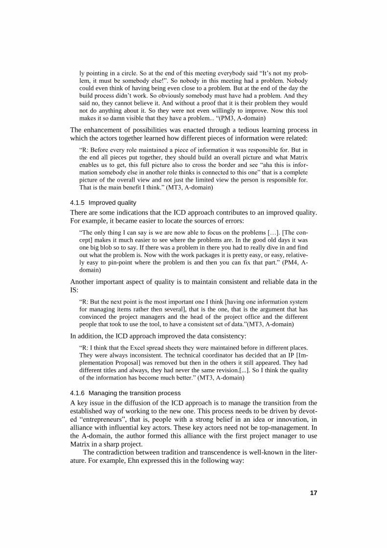
In Figure 9, the main elements in the integration plan are illustrated.
G2U HO
Inter-MSC
G2U HO
a) CAPC
d) 1/APT
Subsequent HO
cases & charging
a) CAPC
d) 1/APT
2G01
2G02
01-09-30
01-10-22
01-09-10
Intra-MSC
G2U HO
a) CAPC
d) 1/APT2G03
01-07-02
New OIP Pack.
d) 1/APT
a) CAPC
01-10-08
Date for
function testFunction
identification
Projects developing
the functionality
Date for system
integration
Traffic light cues indicating the
status of the increments
Increment group, i.e. several
increments managed together
Major system function
Figure 9: A detail of the integration plan in Figure 8.

12
In the 3G development, two major coordination domains were constructed: the S-
domain situated in Stockholm, Sweden and the A-domain situated in Aachen, Germa-
ny. The purpose of these two domains was the same: to provide coordination support
for the development projects. However, these sites developed different parts of the
telecom system. The A-domain projects were developing SW parts only, while the S-
domain projects were developing both SW and HW parts. Furthermore, over the years
these domains had evolved different ways of coordinating development.
Each domain was supported by two logically separated ISs built on the same
platform, the Matrix PDM system from Matrix-One [25]. In essence, this means that
there was no technical interaction between these systems. The main reason for choos-
ing two separate ISs was that achieving consensus about a common way of coordinat-
ing the project was considered unfeasible in the time span available.
In Figure 10, a high-level view of the context models for the S domain is shown.
DESIGN_ITEMAllocated_To
Parent_Child
REQUIREMENT_ITEM
Tested_By
TEST_ITEM
CHANGE_PROPOSAL_ITEM
ChangeControl ChangeControl
Needs
FUNCTION_ITEM
Described_By
DOCUMENT_ITEM
Consists_Of
PRODUCT_ITEM
PROGRESS_CONTROL_ITEMProgressControl
ProgressControl
Impacts
(mhrs)
Depends_on
INCREMENT
Req Coordinator
Designer
Project
PROJECT_ITEM
CMR
Project Manager
ROLE_ITEM
AD Package
System Issue
Design Base
INTEGRATION_ITEM
Input Req
Detailed Req
Figure 10: The S-domain context model (1999)
The elaboration phase of the S-domain occurred approximately between 1998 and
1999. During that period, the following coordination areas were made operational:
Requirement management (REQUIREMENT_ITEM in Figure 10),
Engineering Change Order management (CHANGE_PROPOSAL_ITEM),
Baseline and milestone management (PROGRESS_CONTROL_ITEM),
Test configuration management (TEST_ITEM),
Support for the ICD approach (FUNCTION_ITEM, INCREMENT and
INTERGRATION_ITEM),
Product and document management for the needs of the project
(PRODUCT_ITEM and DOCUMENT_ITEM).

13
The work was mainly carried out by the author, another Ericsson employee and 1-2
consultants in close interaction with key users such as project managers, configura-
tion managers, etc.
In Figure 11, the corresponding context model for the A domain is shown. The
elaboration phase of the A-domain occurred approximately between the end of 1999
and mid 2000.
Feature
WPFFRS IP
(s)WPG
High-level RS
Holds
SIP
ARS, CRS, MRS
Tagged(H)RS Item
Feature Group
prio
Features
DescribedIn*
DescribedIn
DependsOn
Has
Feature Groups
Detailed RS
toAnatomy
RS_IP
RS_SIP
IP_FF FF_WP
SIP_IP
Figure 11: The A-domain context model (2000)
The items in the models signify phenomena that the actors in each domain have found
relevant to coordinate. The nomenclature is mostly Ericsson specific. The most strik-
ing observation is that the context models are completely different. The only items in
common are the encircled ones: “Increment” and “WP” (work package). A work
package is essentially the same as an increment. However, not even the names were
equal in both domains. The increments items differed in practically all aspects such as
attributes, life cycle states, etc.
These observations support the assumption that it would have been very hard to
reconcile the two domains from the outset. In order to achieve the necessary coordi-
nation support these domains had to be constructed independently of each other. The
obvious drawback is that the coordination across the domains had to be done without
IS support.
The ICD approach was in a sense a one-time shot at Ericsson. The specialized IS
support and the application of Domain Construction Strategy in combination with the
anatomy way of working were effective only between approximately 1999 and 2002.
After 2002, the coherent ICD approach began to disintegrate. The context model
turned into a “Common Ericsson Model” maintained by a line organization. The close
interaction between users and developer inherent in the Domain Construction Strate-
gy was replaced by a conventional development strategy, in which the interaction
between users and developer became more remote and formalized. This was partly
due to an outsourcing of the development task to another organization. At the end of
this study (2003), work began to consolidate the A and S domains into one, central
domain for the entire Ericsson company. This means that the integration centric way
of working is still prevalent at Ericsson, albeit in a fashion which in many respects is
completely different from the ICD approach as described in this paper.

14
4.1 Effects
In this section, we will give an account of the effects from applying the ICD approach
in the 3G development. The effects are grouped under a number of effect categories,
and the findings are corroborated with samples of quotations from various actors.
These include project managers (PM), configuration managers (CM) and method &
tools support responsible actors (MT). In the quotations “I” stands for interviewer and
“R” for Respondent. “Matrix”, “database” and “tool” refers to the IS in the ICD ap-
proach. A detailed account of the effects is given in [33].
Taken as a whole, the effects have been profound. Some project managers
claimed that the development of one of the most complex nodes, the so-called Mobile
Switching Centre node (see Figure 8), would not have been possible without the ICD
approach. This is captured in the following quotation:
“Especially for the execution part I think we would not have been able to run this pro-
ject without the tool. I think if you simply look at the number of work packages, the
number of products that we have delivered, the number of deliveries that we have had,
if we would have had to maintain that manually, that would have been a sheer disaster.
[...] we had some, only in my part of the project, some 200 work packages or work
packages groups or whatever you want to call them, deliveries, on the average 2-5 sub-
projects within them 5-10 blocks being delivered, just keeping track of that [...] would
have been a hell of a job.” (PM4, A-domain).
Thus, the fundamental effect is that the ICD approach was a sine qua non for the 3G
endeavour.
4.1.1 Managing evolution and change
This category refers to effects regarding the evolution of the coordination domain and
changes. Two types of evolution of the coordination domain can be identified. The
first one concerns the elaboration phase in the Domain Construction Strategy. This
evolution can be characterized as a “daily build” where changes are made more or
less on the fly during an ongoing project. The other type of evolution concerns a long-
term evolution which is related to impacts from external changes, adding new coordi-
nation support, providing maintenance, etc.
Daily builds
In the elaboration phases between 1999 and 2002, around 200 changes were made in
the A-domain and 500 changes in the S-domain. A necessary prerequisite for the dai-
ly build type of changes is that the implementation in the IS is extremely easy to
change, which is the case with Matrix. The daily build has the drawback that the ap-
plication may turn out to be a patch work which has to undergo major reconstruction.
However, the experiences were that these problems could be mastered.
Long-term evolution
The long-term evolution of the domain should be done gradually and build on exist-
ing knowledge. It should be possible to adhere to known ways of working. One ex-
ample of this is the Engineering Change Order process that evolved from the existing,
document oriented way of working:
“Because that was the point with Matrix, that we should be able to take our process,
which really wasn’t that well documented at that time, and adapt it to the tool. And the

15
tool should be able to do the job that we,... that if we wanted it to work in this way,
then it should be possible to adapt the tool to that.” (CM1, S-domain)
A gradual evolution of the coordination domain was made possible with the ICD ap-
proach:
“Well, the positive effects that we have, that is that we have an integrated project sup-
port system where we have tremendous possibilities to improve, continuously improve
our operations.” (PM2, S-domain).
This meant that the coordination domain could be constructed by attending one coor-
dination area at a time. At the S-domain, requirement management and engineering
change order management were prioritized. At the A-domain, on the other hand, work
package integration management was top priority.
Re-planning
The ever increasing turbulence of the market in general and the 3G market in particu-
lar made re-planning a major issue in the projects. About 500 Engineering Change
Orders had to be considered, which meant that the project, increment and integration
plans had to be continuously updated. The ICD approach was the cornerstone in
building up the capacity for re-planning. Without this, the complexity could not have
been managed.
4.1.2 Enhanced orientation
“Orientation” refers to the ability of actors to orient themselves in the coordination
domain. Some aspects of orientation are awareness of dependencies, focal changes
and traceability.
Dependencies
The anatomy in the ICD approach proved to be a good instrument for signifying de-
pendencies:
“And also based on the anatomy chart, which is also I think a very important mecha-
nism, you see a lot of dependencies both time wise and product wise, etc. So you can
fix things that need to be fixed first and fix problems that are at the end of the project
so to say at a later stage. Of course that is also a key issue.” (PM4, A-domain)
However, the anatomy captures only functional dependencies in the telecom system.
In order to manage all the dependencies expressed in the context model, the Matrix IS
was necessary:
“R: I think for the MSC [Mobile Switching Centre node] there is a clear need for the
tool and I have met now a couple of people who have said: without the tool we would
not have survived the projects. […] I: Is that due to the complexity of the node itself?
R: yes, the complexity of the node, the complexity of the dependencies, time pressure
people have. If you visualize dependencies it is far easier to take decisions.” (PM3, A-
domain)
Focal change
Orientation in a complex situation is alleviated if the attention can be directed to vari-
ous foci while simultaneously maintaining the interdependencies between them. The

16
ICD approach made it possible to direct the attention to any foci inherent in the con-
text model:
“R: You can look at different levels because of... how shall I say that.... you can look at
it on a very overall level and you go down to specific as you want to up to document
status.” (MT4, A-domain)
Traceability
Traceability can be seen as a particular kind of dependency where the purpose is to
follow a path of dependencies from, for example, requirements to customer deliver-
ies. Again, the ICD approach enabled this:
“We have a good support for configuration management, our engineering change or-
ders are in order, our baselines are in order, etc. In addition I think that we have the
possibilities to manage requirements in a good way and make them obvious and we can
achieve a very clear traceability all the way from customer requirements one might
say.” (PM2, S-domain)
4.1.3 Clear separation of concerns
The effects gathered under this heading are related to the separation of a complex
situation into contexts, which are meaningful and comprehensible for the actors. For
example, from the point of view of total project management, the attention is directed
towards the status of each work package and the dependencies between them. On the
other hand, from a single work package point of view, the focus is on the inner of the
work package. The ability to move between these different levels proved to be bene-
ficial:
“Of course there is also something that is maybe also a benefit of the tool is that we do
have different levels of projects. And the tool can really provide support for various
levels, […]. It is one common database with everything in it. It’s just a matter what
kind of information you are interested in. You don’t have to summarize all the data
from lower levels into reports for higher levels, its all in the tool and you can ask some
mechanism to load it, that is very valuable.” (PM4, A-domain)
Another consequence is that the need for the total project management to engage in
coordinating sub-projects has decreased:
“Yes, what is of course also the great benefit, and that is also the feedback we get from
other subprojects, is that you have one common place where all the project area stored
the information. It’s very easy to look up certain things like PA1 [Product Area] needs
the status of a WP [work package] from PA2 and it’s simple to go to the tool and see
what it is all connected to. It means that a lot of the coordination which previously went
via the main project, now can go directly. It’s closely tied to the work package concept
of course. A lot of coordination is now happening on the level it should be and that’s
on the subprojects level and not via the main project any more.” (PM4, A-domain)
4.1.4 Clarifying responsibilities
One effect of the ICD approach was that it became more difficult for actors to escape
their responsibility by pointing in other directions:
“There was always a huge debate whether there is a problem in the build content list or
not. People usually said... if you talk to development projects they always said we don’t
have a problem, it’s him. I will never forget I was in a meeting where they were actual-
17
ly pointing in a circle. So at the end of this meeting everybody said “It’s not my prob-
lem, it must be somebody else!”. So nobody in this meeting had a problem. Nobody
could even think of having being even close to a problem. But at the end of the day the
build process didn’t work. So obviously somebody must have had a problem. And they
said no, they cannot believe it. And without a proof that it is their problem they would
not do anything about it. So they were not even willingly to improve. Now this tool
makes it so damn visible that they have a problem... “(PM3, A-domain)
The enhancement of possibilities was enacted through a tedious learning process in
which the actors together learned how different pieces of information were related:
“R: Before every role maintained a piece of information it was responsible for. But in
the end all pieces put together, they should build an overall picture and what Matrix
enables us to get, this full picture also to cross the border and see “aha this is infor-
mation somebody else in another role thinks is connected to this one” that is a complete
picture of the overall view and not just the limited view the person is responsible for.
That is the main benefit I think.” (MT3, A-domain)
4.1.5 Improved quality
There are some indications that the ICD approach contributes to an improved quality.
For example, it became easier to locate the sources of errors:
“The only thing I can say is we are now able to focus on the problems […]. [The con-
cept] makes it much easier to see where the problems are. In the good old days it was
one big blob so to say. If there was a problem in there you had to really dive in and find
out what the problem is. Now with the work packages it is pretty easy, or easy, relative-
ly easy to pin-point where the problem is and then you can fix that part.” (PM4, A-
domain)
Another important aspect of quality is to maintain consistent and reliable data in the
IS:
“R: But the next point is the most important one I think [having one information system
for managing items rather then several], that is the one, that is the argument that has
convinced the project managers and the head of the project office and the different
people that took to use the tool, to have a consistent set of data.”(MT3, A-domain)
In addition, the ICD approach improved the data consistency:
“R: I think that the Excel spread sheets they were maintained before in different places.
They were always inconsistent. The technical coordinator has decided that an IP [Im-
plementation Proposal] was removed but then in the others it still appeared. They had
different titles and always, they had never the same revision.[...]. So I think the quality
of the information has become much better.” (MT3, A-domain)
4.1.6 Managing the transition process
A key issue in the diffusion of the ICD approach is to manage the transition from the
established way of working to the new one. This process needs to be driven by devot-
ed “entrepreneurs”, that is, people with a strong belief in an idea or innovation, in
alliance with influential key actors. These key actors need not be top-management. In
the A-domain, the author formed this alliance with the first project manager to use
Matrix in a sharp project.
The contradiction between tradition and transcendence is well-known in the liter-
ature. For example, Ehn expressed this in the following way:

18
“[If] I should single out one aspect that to me seems to be the most crucial to design
philosophy, it must be [...] the dialectics of tradition and transcendence in design and
use.” ([11], p. 127)
The most salient expression for this dialectic concerned the use of Matrix instead of
conventional documents. This concerned, for example the management of individual
requirements instead of requirement specification documents. Previously, the docu-
ment was the coordination item that was updated, put under revision control, etc.
Now, that document turned into a report generated from the new coordination items –
the individual requirements. The transition was hard on many occasions. Some per-
sons bluntly refused to use Matrix unless it could be proven that the traditional docu-
ments could be recreated from the IS.
Participation and feedback
The first A-domain project experienced severe problems at the Australian site with
Matrix in the beginning. Both the reliability and performance of the IS was unac-
ceptable (see Section 4.1.8). The main project in Stockholm did not pay enough atten-
tion to this, which caused a lot of frustration:
“Yeah I hope there are some positives to be taken...it is only negative because the posi-
tive side is not coming through. It’s kind of like saying that this doesn’t work, and then
someone says ‘OK here is the patch that fixes it’, then there is a big smile. The unhap-
piness here is that it doesn’t work but the fix doesn’t come through. And that’s where
the frustration is, it’s not so much that tool is slow, it’s the fact that peoples kept saying
it’s slow for so long. It’s not so much that the tool couldn’t do something, it’s that peo-
ple kept saying it couldn’t do it for so long. And it just seems to take such a long time
for things to happen. And we are very detached from the central expertise up there in
Sweden. But I think people can see a lot of positives happening if the feedback is im-
proved.” (MT2, A-domain)
These problems were technically solved later on. However, the problems could have
been much alleviated if measures had been taken early to counteract feelings of being
left alone and disregarded.
Trusting the data in the IS
A major difficulty in all coordination domains was to convince the actors of entering
data into Matrix. There were various reasons for this: lack of support resources, re-
sistance to change established ways of working, poor performance of early versions
of Matrix at distant sites, problems to understand the user interface, etc. However, a
main reason was that the actors did not understand why they had to enter the data.
From their point of view, entering data in a cumbersome IS was just an extra burden.
One strategy to advance the entering of data was to expose the responsible per-
sons in public for not having done their job:
“So taking the database as input for the discussions at the project meetings, that was the
main driver for the subproject manager to put the information there. If there were re-
ports were... all the Work Packages were red just because they didn’t enter the infor-
mation, and this is presented in a project management meeting, then of course the next
time they had updated it.” (MT3, A-domain)
The key issue concerning data reliability is to promote the quality of the data to the
level where the actors feel they can trust it. This can be achieved by creating a chain

19
of dependencies among the actors in such a way that if someone fails to enter the
data, the others will suffer:
“I: Did that [the entering of data] improve much when this decision to use the database
for reports was taken? R: Yes, it was used by several roles we have in the project, and I
think each area, for example the technical coordinator he has used Matrix, and the test
has used Matrix. And as soon as different roles take the reports as input for their activi-
ties you must trust them. That is the driver to motivate all the people to enter the infor-
mation into the tool.” (MT3, A-domain)
4.1.7 Constructing shared meaning
Achieving shared meaning is by no means an easy task. In [33] an illustrative exam-
ple is related. A group of eight actors were discussing the meaning of one item (a
requirement type) in the context model without coming to a conclusion after two
hours. Considering that the entire context model may contain several hundreds of
elements (types, relations, attributes, state sets, access rights, etc.), it is quite easy to
imagine the difficulties of a larger group of actors (say hundreds) to agree on the
meaning of all the elements in the context model. In addition to that, the domain will
change due to external circumstances, new insights, new coordination situation, etc.
The intended effect from the Domain Construction Strategy is that shared mean-
ing emerges in the construction of the domain. There are several indications that this
in fact happened, for example:
“I think that the traceability we used heavily. For we didn’t have one object type just
being on its own, it was always to show impacts of relationships to other, and... what
this traceability...when we talk about relationships in Matrix, then there were different
roles being responsible for the part and that together, all the different roles together,
they build the overall picture then.” (MT3, A-domain)
4.1.8 Enabling IS / IT support
In this section we will give an account for effects concerning the IS / IT support in the
ICD approach. The key enabler of this support was the ease by which the implemen-
tation in Matrix could be changed. This allowed the Domain Construction Strategy to
be fully employed since there is an ongoing iteration between adjusting the context
model and implementing it in Matrix. The basic functionality of Matrix, such as im-
plementation of the context model “on the fly” without re-compilation, logging all
events, defining user roles and access rights, security checks, etc. turned out to be
quite acceptable.
Performance and stability
In each of the A and S domains, a Matrix server was installed. This was accessed
from the development sites globally. No attempt was made to set up a replicated in-
stallation in which the databases could be placed closer to the development sites. This
was considered too expensive and awkward to manage. However, it turned out that
the Ericsson intra-net was not sufficient for the server – client architecture chosen.
Severe performance problems were experienced at Australia and other sites as well.
This state of affairs threatened the continued usage of the tool on several occasions:
“Well, in principle all the PA’s [Product Area responsible], or the subprojects, were en-
thusiastic using the concept because it had benefits for them as well. They could see the
progress in other areas on which they were depending. However we had quite a lot of

20
issues with performance. It simply was very slow outside of EED [the central organiza-
tional unit in the A-domain]. This was a major issue. People complained that just up-
dating one attribute took them 2 hours or so. That simply takes too long. This came
from several sites, Croatia, Australia, Dallas, wherever.” (PM4, A-domain)
Moreover, the stability of the system was poor in the beginning. This situation was
drastically improved with the introduction of a servlet-based web-client. Thus, a ma-
jor lesson is that issues like performance and stability should be up front. Further-
more, the continued evolution of applications must not jeopardize the performance.
User acceptance
The user acceptance of Matrix has in general been low. The user interface was con-
sidered hard to understand. Only with the advent of the servlet-based web-client did
this improve. In this client most of the particulars of Matrix was hidden.
Reports
Somwhat unexpectedly, it turned out that a key success factor in the deployment of
the ICD approach was the availability of various report generators. In Figure 12 an
example of such a report is given:
Figure 12: A web-based report showing information related to work packages (increments).
Another report generator called the Relation Viewer could display relational infor-
mation in a matrix form similar to the dependency matrices defined by Eppinger et al.
[13]. An example of is given in Figure 13:

21
Figure 13: A web-based relational view of an anatomy.
These reports provided a good overview of communicating the status of the project to
everyone involved:
“R: I presented this way of working to them, to the mobile people. And they were real-
ly... oh this is nice and simple and easy to understand for everybody and very effective.
In the end we had our on-line reports. People didn’t even have to go into the system
themselves any more, they could just.... Especially the project managers, the infor-
mation they needed directly from the web with one click in these pre-defined tables.”
(MT4-19-2:05b)
5 Discussion
The underlying tenet of the ICD approach is that issues concerning coordination,
communication and shared meaning must be confronted head-on in order to manage
DSD. Thus, the social aspects should frame the more technical ones, like writing a
piece of software code or doing traditional resource and time planning of projects. In
this section, we will discuss how some DSD challenges are addressed from this per-
spective.
Architectural design
When modelling the architecture of a complex system, a choice of perspective must
be made. In the ICD approach, a functional perspective is taken. The anatomy shows
the architecture of the telecom system in terms of dependencies between functions.
Other aspects are suppressed, for example, the system structure (what parts the sys-
tem consists of). There are mainly two reasons for this choice. The first one is the
conviction that in order to manage complexity, you need to understand how things
depend on each other. The other reason is that the anatomy provides a basis for the
incremental integration of the system from basic functionality to an operational sys-
tem.

22
The architecture plays a key role in the coordination of DSD: “The coordination
of multi-site work needs a common understanding of the architecture of the system to
direct the development the work toward a coherent, working system” ([28], p. 245).
Achieving common understanding is an intentional feature of the anatomy approach.
The anatomy is usually drawn on a singe page that can be placed on a wall or put on a
web page. It is defined in a process where key actors come together and work out the
architecture of the system [23]. In this way, the anatomy provides one view of the
system for all actors, regardless of how they are distributed across geographical and
organizational borders. In other words, it provides a central coordinating mechanism
of multi-site projects.
Project Management
When distributing the development task it is vital to consider group cohesion and task
coupling [31]. Group cohesion refers to variations in language, culture, organization
and countries. A group with large variety in these respects is defined as having low
group cohesion. Task coupling refers to the need of co-presence, proximity and face-
to-face communication.
The concepts of group cohesion and task coupling may be utilized when defining
the increments in the ICD approach. The obvious choice is to define increments that
delineate tasks with high group cohesion and high task coupling. For example, incre-
ments, which according to the anatomy have a large number of functional dependen-
cies, should be avoided since this almost certainly leads to a high degree of task cou-
pling. Another aspect is that the increment plan may be structured with respect to
groups having a high degree of group cohesion.
In the ICD approach, the definition of the anatomy needs a lot of interaction,
communication and face-to-face meetings among actors from various sites. Thus,
anatomy definition is a task that has a high degree of task coupling and low group
cohesion. By participating in this work, the actors will communicate the shared mean-
ing of the anatomy at their home sites. In other words, they will act as liaisons in the
project, something that have been identified as quite important in DSD [6].
Another important aspect of the ICD approach is that all its elements can be uti-
lized in distributing the tasks. For example, the architecture of the system can be de-
fined in such a way it alleviates the definition of tasks with high group cohesion and
low coupling. This is of course only possible in situations where the architecture is
not settled, for example when developing a new system.
Furthermore, the ICD approach enhances commitments and responsibilities. The
increment and integration plans clearly signify which groups are responsible for what.
Moreover, the dependencies between groups are evident. This is also amplified by the
traffic light cues for signalling the progress of the project.
Multiculturalism
Multiculturalism in DSD implies both risks and possibilities. Strong group cohesion
may be advantageous in developing a certain increment. On the other hand, multicul-
turalism may lead to misunderstandings and conflicts. Here, we shall discuss one
aspect of multiculturalism: the balance between common and local ways of working.
There are different opinions about the role of commonality in DSD. For example,
Ebert and De Neve from Alcatel recommend that all sites working with the same type
of products should use common processes, methods and terminology [12]. On the

23
other hand, Battin et al. from Motorola regard not imposing a common process as a
key strategy in DSD [6]. Even though it is desirable to use the same tools, methods
and processes throughout the project, this is seldom, if ever, an option. This is espe-
cially so if the DSD project is a more or less temporary configuration of otherwise
independent organizations.
The distribution of local versus central control has been a recurrent issue at Er-
icsson. Decentralization driven too far has caused problems:
“We can state that the decentralization of... the method and process work that we have
today, that our units within the Ericsson company have their own subsidiaries work
very differently, that we work very differently within one and the same company. Even
if we should know this after this many years so, instead of consolidating into a unified
way of working, it has diverged into 40 different ways of working.” (PM2, S-domain)
On the other hand, enforcing a common way of working is also problematic:
“I know there are some initiatives and try to come up with one object model for all pro-
jects within Ericsson. And I think that’s a little bit trying to search for the Holy Graal.
[...]. I mean you can even see how different the ways of working are within our subpro-
jects at this moment because of the characteristics of the products and the areas where
they are located and so on. To even keep one common way of working for that is really
quite a challenge. So if you try to come up with one way of working in the projects
within Ericsson, a common object model for that, I think that that’s way too ambitious
at the moment.” (PM4, A-domain)
The ICD approach provides a framework managing these matters. The integration of
increments can be coordinated without imposing a common way of working in each
increment. Moreover, even if the Domain Construction Strategy assumes that coordi-
nation domains are constructed locally, some elements in each domain can be en-
forced in order to enable coordination between the domains. Examples of such ele-
ments are the work package definition, the identification rules for products and doc-
uments, the IS platform, etc. Thus, the effect of the ICD approach is that it problemiz-
es the issue of balancing centralization versus decentralization in DSD.
IS / IT support
The result from the Ericsson practice underscores the importance of securing the ca-
pacity of the IT infrastructure and ISs before implementing the ICD in DSD projects.
Moreover, issues of usability, user training and user support must be addressed.
In addition, the ICD approach requires a high degree of flexibility of the IS. Dur-
ing the construction of the coordination domain, the implementation of the context
model needs to be frequently modified. This also applies to the long-term evolution of
the domain. The flexibility requirement rules out most large, globally accessible IS,
such as PDM and ERP (Enterprise Resource Planning) systems, as candidates for the
ICD approach. In fact, to the best of our knowledge the Matrix PDM system from
Matrix-One is so far the only IS fulfilling the flexibility requirement.
A main issue all throughout the deployment of the ICD approach was the role of
Matrix in the overall IS architecture at Ericsson. IS architectures have been extensive-
ly discussed in the literature (e.g. [2], [4], [7], [10], [18], [30]). From the ICD point of
view, the IS architecture must permit different IS implementations in each coordina-
tion domain. This can be achieved by using different IS platforms in each domain.
Often, this is the only option available since a certain platform may be already in

24
place. However, it is more advantageous if the IS platform can be the same in all co-
ordination domains since this facilitates the interaction between the ISs. For example,
information exchange of increment status in the A and S domains respectively would
have been much easier if the two Matrix databases had been connected. Technically,
this is quite possible, for example, through federated databases or an XML-based
information exchange.
Another aspect of the IS architecture is related to the roles of different ISs in each
domain respectively. In both the A and S domains, the intention was to manage as
many types of coordination items as possible in Matrix. However, in most existing IS
architectures this is not the case. Usually, there is one IS for each coordination area,
i.e., one IS for requirement management, one for engineering change orders, one for
test management, etc.
As can be seen from the results, the ability to manage all types of items in the
same IS is very advantageous. Some reasons for this are:
Interfaces between ISs in the coordination domain are not needed.
The coordination information is consistent.
There is a homogeneous worldview of the entire coordination domain.
Changes, which are common to all coordination areas, are easier to implement.
The ability to react to changes is higher.
There will still be a need to interface the coordination domain IS to other ISs. For
example, the management of files for software development should be done by spe-
cial purpose SW configuration management tools. However, such interfaces will be
on the border of the coordination domain rather than inside it.
Problems related to the ICD approach
Besides the Ericsson specific problems already discussed there are some problems of
a more general nature associated with the ICD approach. Defining the anatomy is
often hard work. The actors may disagree about what to include in the anatomy and
the level of detail in it. Sometimes there are also opposing views of how the system
actually works. Moreover, the ICD approach enforces a new mind setting which is not
accepted by all actors.
Some other problems might be:
The IS in the ICD approach can in principle replace specialized management ISs
supporting, for example, requirement management, engineering change order
management, etc. However, actually carrying out such a replacement is problem-
atic.
The IS may not be compliant with corporate IS strategies. For example, the or-
ganization may have decided for an ERP system such as SAP to support multi-
site processes. Quite naturally, it is desirable to use this system in as many areas
as possible. Even if a system as SAP would be very inadequate for the ICD ap-
proach due to low flexibility, it may be difficult to get acceptance for introducing
yet another IS platform in the organization.

25
The Domain Construction Strategy presumes an iterative IS development method
where the implementation is frequently changed. From a conventional engineer-
ing point of view, changes indicate a badly specified system. Thus, the ICD ap-
proach entails a new understanding of what characterizes good engineering prac-
tice.
Currently, there are no established criteria for identifying an optimal set of coor-
dination domains.
5.1 The construction of shared meaning
The difficulties in constructing shared meaning emanates from lack of objective crite-
ria by which a “correct” model can be evaluated. Like Wittgenstein, we believe that
the meaning of a phenomenon is determined in the social activity in which actors
participate [36]. As long as a meaning of a word or sign brings about actions with
intended consequences, the word is “correct”. When misunderstandings or disagree-
ments occur, the meaning of the word must be considered and reflected upon. This
means that the only criteria by which “correctness” can be resolved is usability. For
example, “WP” in Figure 11 signifies the phenomena “work package” in the S-
domain. However, outside Ericsson (and in fact outside the S-domain at that time)
“work package” has other connotations.
Thus, disputes regarding meaning cannot ultimately be resolved around the table
in a conference room. The context model and its associated IS implementation must
gain their credibility on the combat field where projects are making use of them in
their struggle to develop systems. If the context model is detached from the practice,
it will rapidly turn into a reified phenomenon without practical relevance.
5.2 Limitations
The ICD approach has, to the best of our knowledge, been applied only in the Erics-
son development practice. This raises questions about the transferability of the results
to other DSD enterprises. As pointed out, the development of telecom systems can be
seen as a paradigmatic area comprising most, if not all, of the challenges in DSD.
However, this is an issue for further research.
Another issue concerns the IS used in the Domain Construction Strategy. Again,
the experiences so far comes from one particular IS, the Matrix PDM system. It is
desirable to identify general criteria by which other IS could be evaluated for use in
the ICD approach.
In this paper we do no treat impacts from the SW development model on the ICD
appraoch. Nor do we treat the SW configuration management of source code files
during the writing of the SW. This is an important subject in itself which is treated
extensively in the literature. For example, interfacing SW configuration management
and engineering is discussed in [8].
6 Conclusions
We have presented the ICD approach of coordinating DSD tasks at Ericsson. The
approach addresses many of the challenges inherent in DSD; above all those associat-
ed with social aspects such as communication, coordination and shared meaning con-
struction. Although the approach so far is limited to one company, the results are

26
encouraging. Extraordinary complex nodes in the 3rd
generation of mobile systems
have been successfully developed subject to very demanding circumstances. Our
main conclusion is that the ICD approach can be apprehended as a “bridgehead” into
conquering new insights in managing distributed software development.
References
[1] N. Adler, Managing Complex Product Development – Three approaches, EFI, Stockholm
School of Economics. ISBN: 91-7258-524-2, 1999.
[2] B.R. Allen, A.C. Boynton, Information Architecture: In Search of Efficient Flexibility,
MIS Quarterly, December 1991, pp 435-445.
[3] J. Anderstedt, U. Anderstedt, M. Karlsson, M. Klasson M, Projekt och helhet – att leda
projekt i praktiken, Författares Bokmaskin (in Swedish), Stockholm,2002, ISBN: 91-7910-
380-4.
[4] K. Axelsson, Metodisk systemstrukturering - att skapa samstämmighet mellan informat-
ionssystemarkitektur och verksamhet, Dissertation No. 1, Department of Computer and In-
formation Science, Linköping University, Linköping (in Swedish), 1998.
[5] R. Baskerville, T. Wood-Harper, A Critical Perspective on Action Research as a Method
for Information Systems Research, Journal of Information Technology 11, 1996, pp. 235-246.
[6] R. Battin, R. Crocker, J. Kreidler, K. Subramanian, Levering Resources in Global Soft-
ware Development, IEEE Software, March / April, 2001, pp. 70-77.
[7] Broadbent M, Weill P (1997): Management by Maxim: How Business and IT Managers
Can Create IT Infrastructures, Sloan Management Review, Spring 1997, pp. 77 - 92.
[8] I. Crnkovic, U. Asklund, A. Persson Dahlqvist, Implementing and Integrating Product
Data Management and Software Configuration Management, Artech House, London, 2003.
[9] D. Damian, Global Software Development: Growing Opportunities, Ongoing Challenges,
Software Process Improvement and Practice, 8, 2003, pp. 179 – 182.
[10] M.J. Earl, An Organizational Approach to IS Strategy Making, in: M.J. Earl (Ed.), In-
formation Management - The Organizational Dimension, Oxford University Press, 1996, pp.
136 - 170.
[11] P. Ehn, Work-Oriented Design of Computer Artefacts, Arbetslivscentrum, Stockholm,
Sweden, 1998.
[12] C. Ebert, P. De Neve, Surviving Global Software Development, IEEE Software, March /
April, 2001, pp. 62 – 69.
[13] S.D. Eppinger, D.E. Whitney, R.P. Smith, D.A. Gebala, A Model-Based Method for Or-
ganizing Tasks in Product Development, Research in Engineering Design, 6(1), 1994, pp. 1-
13.
[14] M. Eriksson, J. Lilliesköld, N. Jonsson, D. Novosel, How to Manage Complex, Multina-
tional R&D Projects Successfully, Engineering Management Journal, Vol.14, No.2 June 2002,
pp. 53-60.
[15] G. Goldkuhl, A. Röstlinger, Expanding the scope: From language action to generic prac-
tice, in Proceedings of the 4th International Workshop on the Language Action Perspective
(LAP99), Copenhagen, 1999.
[16] R. Heeks, S. Krishna, B. Nicholson, S. Sahay, Synching or Sinking: Global Software
Outsourcing Relationships, IEEE Software, March / April, 2001, pp. 54-60.

27
[17] J. Herbsleb, D. Moitra, Global Software Development, IEEE Software, March / April,
2001, pp. 16-20.
[18] M.Å. Hugoson, Verksamhetsbaserad systemstrukturering, NordDATA90, Göteborg, pp.
267-274 (in Swedish), 1999.
[19] W.S. Humphrey, The software engineering process: definition and scope, ACM
SIGSOFT Soft-ware Engineering Notes, Proceedings of the 4th international software process
workshop on Representing and enacting the software process, Vol. 14, 4, pp. 82-83, 1998.
[20] E.A. Karlsson, L.G. Andersson, P. Leion, Daily build and feature development in large
distributed projects, Proceedings of the International Conference on Software Engineering
ICSE 2000, IEEE CS Press, Los Alamos, California, 2000, pp. 649-658.
[21] R. Kraut, L. Streeter, Coordination in Software Development, Communications of the
ACM, Vol. 38, No. 3, 1995, pp. 69 -81.
[22] R. Larsson, Coordination of Action in Mergers and Acquisitions - Interpretative and Sys-
tems Approaches towards Synergy, Dissertation No. 10, Lund Studies in Economics and Man-
agement, The Institute of Economic Research, Lund University Press, 1990.
[23] J. Lilliesköld, L. Taxén, M. Klasson, Managing complex development projects – using the
system anatomy, 2005, (in progress).
[24] T. Malone, K. Crowston ,The Interdisciplinary Study of Coordination, ACM Computing
Services, Vol. 26, no 1, 1994, pp. 87-119.
[25] Matrix-One Inc: http://www.matrixone.com/index.html, (accessed Feb, 2005).
[26] I.R. McChesney, S. Gallagher, Communication and co-ordination practices in software
engineering projects, Information and Software Technology, 46, 2004, pp. 473-489.
[27] U. Melin, Koordination och informationssystem i företag och nätverk, Linköping Studies
in Information Science, Dissertation No. 6, Institutionen för datavetenskap, Linköpings uni-
versitet (in Swedish), 2002.
[28] P. Ovaska, M. Rossi, P. Marttiin, Architecture as a Coordination Tool in Multi-site Soft-
ware Development, Software Process Improvement and Practice, 2003, 8, pp. 233-247.
[29] R. Prikladnicki, J.L.N. Audy, R. Evaristo, Global Software Development in Practice Les-
sons Learned, Software Process Improvement and Practice, 8, 2003, pp. 267-281.
[30] T. Reponen, Organizational information management strategies, Information Systems
Journal, no. 4, 1994, pp. 27-4.
[31] S. Sakthivel S, Virtual workgroups in offshore system development, Information and
Software Technology (in press).
[32] T.R. Schatzki, Introduction: Practice theory, in: T.R. Schatzki, K. Knorr Cetina, E. von
Savigny (Eds.), The practice turn in contemporary theory, Routledge, London, 2001.
[33] L. Taxén, A Framework for the Coordination of Complex Systems’ Development. Disser-
tation No. 800. Linköping University, Dep. of Computer &Information Science, 2003. Availa-
ble at http://www.ep.liu.se/diss/science_technology/08/00/index.html (accessed Feb 2005).
[34] L. Taxén, Interactivity and contextuality in organizational semiosis, Proceedings of the 7th
International Workshop on Organisational Semiotics, OS 2004, Setúbal, Portugal, July 2004,
pp. 97-111.

28
[35] L. Taxén, J. Lilliesköld, Manifesting Shared Affordances in System Development – the
System Anatomy, ALOIS*2005, The 3rd
International Conference on Action in Language,
Organisations and Information Systems, 15–16 March 2005, Limerick, Ireland .
[36] L. Wittgenstein, Philosophical investigations, Basil Blackwell, London, 1958.
[37] R.K. Yin, Case study research. Design and methods, Sage, London, 1989.