Embed Size (px)
Citation preview

C.P. No. 1055
MINISTRY OF TECHNOLOGY
AERONAUTICAL RESEARCH COUNCIL
CURREN J PAPERS
An Experimental Investigation of
Laminar Heat Transfer in a Uniformly Heated Tube
Rotating about a Parallel Axis
W D Morris,
School of Applred Science,
Unrversrty of Sussex
LONDON: HER MAJESN’S STATIONERY OFFICE
I969
Price 5s Od[25p] net


C.P. No.1055*
september, 1968
An Experimental Investigation of Laminar Heat Transfer in a Unlfomiiy Heated Tube Rotating about a Parallel Ans
- By - W. D. Morns,
School of Applied Science, Unwersity of Sussex
The results of an experimental investigation whzoh stubes the influence of rotatlondly induced buoyancy on heat transfer in a tube which rotates about an axis parallel to xtself is presented. Data obtained with water and IO@ glycerol appear to confirm the qualitative description of flow given by two theoretxal analyses. A reliable qualitative method of predxtion is stall unavailable.
I. Introduction
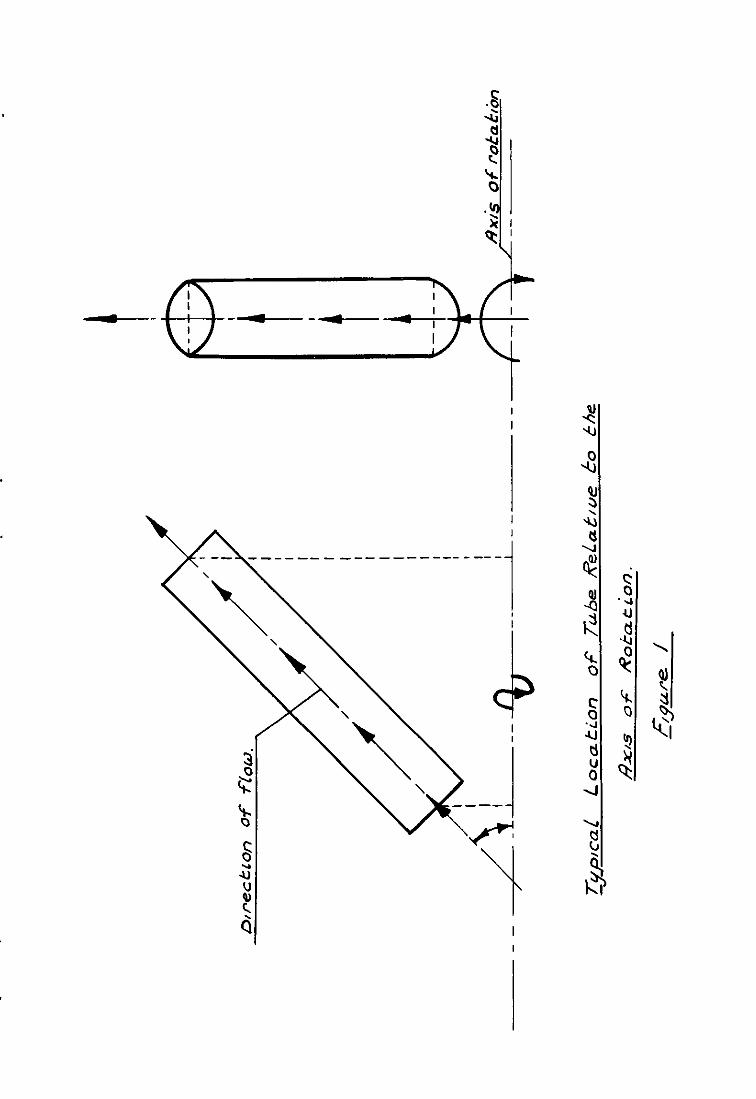
When a fluid flows through a tube which is rotating about some arbitrary sxx, as shown in Fig. 1, the presence of centripetal and Coriolis dcceleratlon components may cause secondary flow to occur in the planes perpendicular to the axis of the tube. Flow conflguratlons of tbs type are often used 111 the design of cooling systems for certain rotating compon- ents, notably turbine rotor blades and the rotor conductors of large eleotri- cal machines. Under these circumstances density gradients in the fluid resulting from the temperature ktributzon give rise to buoyancy forces which further influence the flow field. When the angular velocdy of the tube is large these buoyancy effects must be taken into account in the desxgn calod.a- tlons. However, lxttle information is currently available concerning the influence of rotation on heat transfer and flow resistance. A case of particular interest is that where the axis of the tube is parallel to, but displaced from, the axis of rotation. This system is used for the forced cooling of electrical nachme rotor conductors and is of current importance in the design of generator sets in the power range 500-1000 MW where water cooled rotor oonduotors are employed.
Morr~s"~ considered established l.aminar flow in this type of system both with snd without heat trs.nsf@~: For a uniformly heated tube it was shorn, using a series expsnslon teobniqtie-for the solution of the basic conservation
equations,/ ______________________/-__-________-_----
'Beplaces A.E.C.30 526

-2-
equations, drop data.
that si@tiicant changes occurred in the heat transfer and pressure However, the solutions presented were restricted to low rotational
speeds and heat flux owing to the form of the series used for solving the equations. The influence of the earth's gravitational field along the axis of the tube was slso included in the analysis. This flow geometry comprised part of a thermosyphon circuit tested by korris3 and Davies and horris 4 which had a proJected application for cooling the rotor conductors of electrical prime movers. In practical applications using this type of rotating cooling geometry it is unlikely that conditions of established flow will occur and Humphreys, L'orris and Barrow5 presented the results of an experimental investiga- bon using alp as the working fluid 111 the entry region. me Peuvre6 has also presented the results of an experimental programme where this cooling system is used for the cooling of the rotor drums of electrical prime movers.
Mori and Nakaysma' made a theoreticsl appraisal of this problem for established larmnar flow and uniformly heated walls. These authors assumed a gross secondary flow consistent with high rotational speeds and subsequently derived heat transfer and pressure drop &ta for a variety of Prsndtlnumbers. They also showed that the influence of Coriolis forces was significant.
It is the purpose of the present communication to show that experimental data derived with water and glycerol for this rotating configuration shows quali- tative agreement with the predictions of Mori and Nakayama. Horvever, before the experimental details are presented a brief review of the two knovm attempts to obtain a theoretical solution will be made. Thu 7d.l also serve to illus- trate the salient features of the flow regime obtained with this rotatlng system.
2. Review of Current Theoretical Work
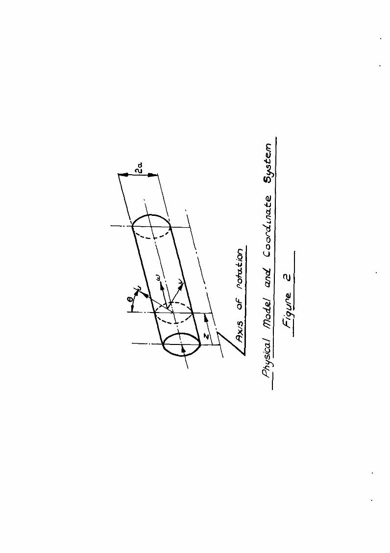
The severity of the analysis of the flow and heat transfer behaviour in the rotating tube considered here may be illustrated by a brief consideration of the qualitative features of the flow involved. Fq. 2 shows the physical model and also indicates the co-ordinate system which will be used.
Under the influence of the radisl component of acceleration the cooler apd thus less dense particles of fluid tend to move towards the outer portion of the tube periphery. Conversely the warmer fluid near the heated walls moves towards the axis of rotation and thus sustains a buoyancy motivated secondary flow III the cross section of the tube. Vhen one further considers the axial flow slang the tube it is apparent that the migration of fluid in the cross stream direction and its associated x-distribution of momentum produces an increase in the resistance to flow. This is important as it affects the design of the pumping equipment in situations which utilise this cooling geometry. In fact it can be shonn that, as a result of the secondary flow, the axial velocity profile deviates from its symmetrical form tith a stationary tube so that the location of the point of msxunum velocity moves towards the axis of rotation. The secon- dary flow also increases the heat transfer from the tube surface to the fluid.
We require a theoretical solution which permits evaluation of the velocity components m each of the three co-ortite directions, the pressure distribution and the temperature distribution. When this has been achieved the calculation of heat transfer and flow resistance is but an easy step.
The theoretical attempts currently available have been restricted to the case where the tube is uniformly heated and the properties of the fluid, with the exception of density, are invariant. Also, distances along the tube sufficiently removed from the entrance to enable the assumption of a velocity
field/

-3-
field which is only weakly dependent on axlallooation have been considered.
Using these assumptmns the present author2 obtained the following laninar flow equations. (Symbols are as defined in the List of Symbols).
Conservation of Momentum
au v au va 1 ap u-+- -_-=_- -+y ar r a0 L‘ P ar
a7 v av uv I av u-+- --+-=-- --+v
ar rae r PT a8 [
Y pv--+-
?? J ;]-Ho’B [Tn-TISinB
aw v aw 1 ap u-+- -=-- -+vv8w
ar r a8 P a2 - - (3)
Conservation of Uass
a(m) ar -+- = 0
ar ae l ** (4)
Conservation of Enerfv
aT Y aT aT u-+ - - + w - = aV”T *-* (5)
ar r ae a2
By assuming the existence of a weak secon&y flow solutions for the velocity and tenperature fields were subsequently derived by expanding the solution about the Imown result for i non-rotating tube. As a result the following expressions for a resistance coefficient, cf , and Nusseltnumber, Nu,, were calculated
16
cf = Re 7, _ PL
O*210;)(Rep Ra1/4608)* I' a-0 (6)
where a ap cf =-x
(Fanning friction factor) *** (7)
m a3 ap
Re =--- (Pseudo Reynolds number) a** (8) P 43% as

-4-
BHP r a’ Rar = (Rotational Rayleigh number) **- (9)
IZV
The above definitions of the resistance ooefflcient and Reynolds number become those usually assoolated with pipe flows where the pipe is statzonary.
[a’ Nu =
- (Re Ral/d')s (e' + f'Pr + g'~rs)] m *.-(IO)
Gj' - (Rep RaI/d')a (n' + s'F'r + t'Prs)]
where
a’ = 0.2500 d’ =&608 et = 090328
f' = 0~0000 g' = o=co18 j' = O-0417
n' = 0*0133 5' = o-aI t' = PWOT
9 Nu, =
e(Tpu - Tm) *-(II)
The definition of Num given above uses the difference between the temperature of wall and the integrated mean fluid temperature (as obt&ned by simple integration of the temperature profile) as a representative temperature difference for the motivation of heat transfer. In praotxe one uses the mixed mean or bulk temperature, Tb , of the fluid. A Nusselt number involving Tb may be cslculated but the algebraic labour involved is considerable.
Because of the reqwement of a weak secondary flow for the applica- bility of equations (6) and (10) these solutions must be restricted to low rotational speeds and heating rates. Indeed, extrapolation of the results into regions where the product of Be and Ra is large indicates the "run awsy" nature of the solution technique. This point is illustrated in Fig. 3. However, the following interesting features emerge from the solutions.
Sample calculations indxate that increases in the resistance to flow and heat transfer result even with the weak secondary flow oonsxlered and that the proportional impairment in reslstsnce can be greater than the improvement of heat transfer. This is an important feature when design assessment is being made. Also even though the influence of Corlolis force notifies the velocity and temperature fields it has no subsequent influence on the heat transfer and reszstsnce to flow.
It is unlikely in practical situations that .the rotational speeds and heat transfer rates are low enough to produce only we@ secondarJI flow. Accord- ingly, Mori and Nakayama7 considered the case where the secondary flow in the central regzon of the pipe was intense enough to enable gross assumptions concern- ing its nature to be made. Thus by assuming that the cross section of the pipe may be treated as a core flow where shear and heat transfer is dominated by secondary flow effects snd a region near the wall of pseudo boundary layer nature, these authors proceed to develop expressions for relatzve increases of Nusselt number snd resistance coefficient using a momentum integral technique. These
increases/
increases are based again on known with the same boundary conditions. given below
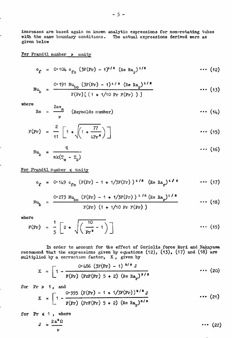
For Prandtl number 8 unitx
-5-
analytic expressions for non-rotating tubes The actual expressions derived were as
Cf = 0*1oJ+ Cfo (3F(Pr) - l)l" (Re Rar)"s -a- (12)
N% = O-191 Nu.,~ (jF(Pr) - l)i's (Re Rar)"'
F(Pr)[(l + l/IO & F(Pr) ) ]
where 2anr
Be = a (Reynolds number)
I? 4 4.31 F(Pr) = - I+ l+-
q Ny, =
"k(T, - Tb>
-*' (13)
a-* (14)
-‘a (15)
9-s (16)
For Prandtlnumber 4 unity
Cf = O-149 cfo (F(Pr) - 1 + 1/3F(Pr))"s (Be Rar)"' --* (17)
N% = 0.273 Nu,, (F(Pr) - 1 + 1/3F(Pr)) 'Is (Re Ra,)"'
F(Pr) (1 + l/IO Pr F(Pr) )
where
F(Pr) = 1 5P+rnl
31 order to account for the effect of Coriolis force Kori and Nakayama recommend that the expressions given by equations (12), (13), (17) and (18) are multiplied by a correctlcn factor-, K, given by
K= l- II
0~486 (JF(Pr) - 1) *" J
F(Pr) (PrF(Pr) 5 + 2) (Re Rar)s's **- (20)
for Pr 3 1, and 0.995 (F(Pr) - 1 + l/~(~))""J
*** (21) F(Pr) (fiF(Pr) 5 + 2) (Re Rar)"s
for Pr ( 1 , where
J = 2a’R
”
e-0 (22)
1,
-6-
3. Descrs.ption of Apparatus
The experlmentd data to be reported in this paper was obtained using * rot*tf% thermovphon apparatus originally designed for the investigation of thermosyphon characteristics. been presented by Morris3 .
A detailed description of the equipment has However, for the sake of completeness, a brief
description of the salient features will now be given.
A tubuhr closed loop in the form of a rectangle ADCD was constrained to rotate about the centre-line of the limb CD, as illustrated in Fig. I+. The limb CD formed part of a built up rotor which could be rotated at speeds in the range 0 - 300 rev/man. with various fluids.
The circuit ABCD could be completely filled
The test section itself consisted of a copper rod 23.&nm external d.i*mder with a 6*35mm diameter hole bored through the centre. Pyrotenax heating cable was embedded 111 a helical groove machined on the outside of the test SeCtlOll and sliver soldered at a number of positions to ensure good thermal contact. The heating cable was composed of Nichrome resistance wire sheathed in a thin walled tube of stainless steel. Mutual electrxsl insulation between the resistance wire and the sheath was achieved with highly compressed magnesium oxvie powder. The nominal length of the test section was 304'8mm, giving a length to diameter ratio of 48.
Nickel chrome/nickel aluminium thermocouples were soldered at both ends of the heated portion of the test section and also at a location 24 diameters downstream of the entry station. It was at this location that the heat transfer measurements were evaluated. Both ends of the test section were sealed with threaded end caps which were fitted with a copper/constantan thermocouple t0 permit measurement of the fluid temperature at the inlet and exit stations.
All thermocouple ssgnsls were taken to the stationary measuring equip- ment via a miniature instrumentation slip ring assembly located at one end of the rotor. External heat loss was reduced by covering the outside of the heater with a layer of refactory cement approximately 6mm thick. The heater assembly cotid easily be removed from the apparatus and the flow circuit was completed by fitting the short copper tubes seen at the inlet snd exit stations into perspex radial limbs BC and DA.
During operation, the fluid in the limb CD was cooled using mains water flowing inside a coil fitted within this limb. Rotary seals at each end of the rotor permitted this secondary coolant to flow into and out of the appara- tus.
The fluid under test is thus caused to circulate within the closed loop owing to the well tiown thermosyphon effect, the rate of flow being governed by the heat tiansfer from the test section for a given geometry of flow.
Direct measurement of the flow rate achieved COdi not be performed in this particular rotating test section. However this parameter could be calculated using a heat balance method after making measurements of heater Power consumption, fluid temperature rue and external heat loss from the test Section. The heat 10s~ at any operating condition was determined from a series of heat loss calibration experiments performed with the interior of the test section filled with granulated cork.
-7-
Two experimental programmes were performed using water and lOC$ glycerol as the test fluids. Tests nere ccnauctea at rctatlcnal speeds of 50, 100, 200 and 300 rev/Lnm svhlch, for the apparatus used, gave centre-line centripetal acceleratlcns in the range 0 - 15g.
4. Results and Dlscussicn
The required dimensionless parameters derived from the test data obtained with water are shown plotted UI Fig. 5 as Nub against Re Rar . It is seen that it 1s pcsslble to discern separate lines for each of the four rctatumal speeds used and that the relative spacing 1s such that, for a given value of Be Bar , the heat transfer is reduced at the higher rotational. speeds. Although for each individual. data point It was not possible to control the value of Pr (because of variations in the prcpertles of the fluid) observation of the range of Pr indicated that a mean value in the region of 6 was applicable. Consequently a reference line calculated from the results of bicri and Naksyama at Pr = 6 has been drawn for convenience of Illustration.
It is seen that, although the test data is generally higher than that predzcted, the data can be correlated by series of lines mhzch are parallel to the predlctlcn. Further, the parameter J , which relates the influence of Corm133 force to vlsccus force, also var~s ever each data point at a given rctatlcnal speed. At the naxmum speed of 300 rev/&n this parameter had a value in the re@cn of 700. Consequently for J = 700 the ccrrectlcn factor suggested by Mcri and Nakayama has been used and the result is shown m Fig. 5.
Theoretically It appears that the influence of J is not too significant in this case. However the test data shows a much greater sensitzvity to J than suggested theoretically. It was found pcsslble to derwe an empirical equa- tion which correlated the data for water and which allowed for the influence of J. The actual. correlation was
NI+, = 25.7 (Re Ra;)"s J"" -'* (23)
and 1s shown plotted, together with the test data, in Fig. 6.
It should be noted that the test data was taken at an sxial lccatlcn Zl+ diameters dcmstream from the entrance. It is likely wzth water that the influence of the entrance is still being felt and that sny induced swirl on the fluid from the ducting upstream of the test section itself has had lnsuffrcient distance to decay. There remains as a result the unresolved point as to what extent J IS reflecting the effect of Ccrlclis force and entrance effects.' The entry effect WLI.ZL of ccurse also be dependent on the speed of rctatlcn. This effect of induced entry swirl has also arisen in the work of Humphreys, Barrow and Mcrr1s5 where tests with air in the lower turbulent range mere conducted.
One mould expect the effect of J to be less pronounced when a fluid of high Pr was used in view of the asscclated large visccszty whether J reflected the effect of Ccriolis force cr entrance ccnditlcns. Acocrdingly, data for large values of Pr should be more likely to correlate on a single line when plotted as Nub against Re Bar . The data cbtalned mth IO@ glycerol as the
test fluid is shown plotted in this form ir Fig. 7 and indeed it was found impossible to discern separate lines at each of the rctatlcnsl speeds. Aithcugh cnce mere the Pr varied throughout the experimental programme, a mean value of
about/
-a-
about 1000 was taken for the reference line of Mori and Nakayama. As before the theoretIca line underestimates the test data but has a similar gradient.
The fact that mlth both fluds the theoretical predxtxons fall significantly below the test data IS easy to explain. Both attempts to pre- dict the effect of rotation on heat transfer base their calculatxons on theoretl- cal conditions for a non-rotating tube. That is on the classical work of Nusselt for a unrformly heated tube. Thus work which 1s reported by Goldstein8 ignores the temperature dependence of the properties and as a consequence a constant value for N % or Nu results. This independence of heat transfer on Be and Pr is well known To be contrary to experMents.l evdence. Conse- quently as the present analyses reduce to the Nusselt result when the rotational speed is zero the entire range of numerxal predictions must underesti.mat& the true state of affarrs.
5. Concluding Remarks
In conclusion, the following general remarks pertaln to the getieral State of tiovrledge for this particular rotating system.
For the case of laminar flow both the currently available theoretxal attempts fad to permit reliable yed.xtion of the heat transfer and pressure drop and serve only to highlight some of the sallent physical features of the flow. Both analyses appear to become invalid when, in the case of MOITXS, extrapolated towar& higher values of Re Rar and, in the case of Mori ad Nskayama, towards the lower Re Rar range. There is need for a more detailed
analysis whxh ideally should account for entrance effects and also a temperature dependent vlscoslty.
There is a definite lack of reliable experimental data particularly in the case of pressure drop measurements. A research facility capable of opera- ting at IOOOg is currently being designed at the School of Applied Science, University of Sussex. This apparatus will use air as the working fluid and mW be fitted mdh heated test sections 171th length/dzameter ratios up to 100. It is envxaged that pressure drop data will also be taken.
-9-
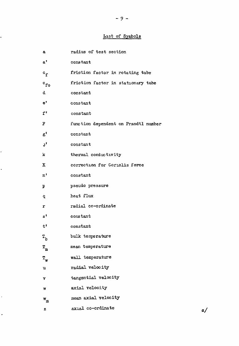
List of Symbols
8
a’
Of
Cfo a
e'
f'
F
g'
J'
k
x
n'
P
9
r
S'
Jc'
Tb
'p,
Tw u
v
w
WITI
s
radius of test section
oonstant
friction factor in rotating tube
friction factor in statxonary tube
constant
constant
constant
fmotion dependent on Prandtl number
constant
constant
thermal conductivity
correct3.on for Gor~olis force
constant
pseudo pressure
heat flux
raaial co-ordinate
constant
constant
bulktemperature
mean temperature
wall temperature
r&al velocity
t~gential velocity
axial velocity
mean axial. velocity
a~2.d co-ordinate

- IO -
a
P
P
v
R
e
Y
$
thermal. diffusivity
expansion coefficient
density
kinematic viscosity
angular veloczty
angular co-ordinate
inclination of tube relative to axis of rotation
gradlent of wall tenperature
Dimensionless Groups
J rotational Reynolds number
Re Reynolds number
Re P
pseudo Reynolds number
Rar rotational Bayleigh number
Pr Frsndtl number
N% Nusselt number based on bulk temperature
n"m Nusselt number based on mean temperature
N"O Nusselt number for stationary tube
References/
- 11 -
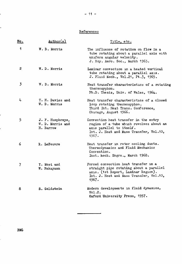
References
No.
1
5
8
Buthods
W.D. Morris
W. D. Morris
W. D. Morris
T. H. Davies and W. D. Morrlrr
J. F. Humphreys, W. D. Morris and H. Barrow
B. LeFeuvre
Y. Mori and w. Nakayama
S. Goldstein
Title, etc.
The mfluence of rotation on flow in a tube rotating about a parallel axis wzth umform angular velocity. J. Roy. Am-o. Sot., March 1965.
Laminar convection XI a heated vertical tube rotating about a parallel axis. J. Fluxd Meoh., vo1.21, Pt.3, 1965.
Heat transfer characteristxs of a rotating thermosyphon. Ph.D. Thesis, Univ. of Wales, 1964.
Heat transfer charsoteristxs of a closed loop rotating thermosyphon. Thud Int. Heat Trans. Conference, Chxago, August 1966.
Convection heat transfer in the entry region of a-tube whxh revolves about an axis paralJx1 to itself. Int. J. Heat and Mass Transfer, Vol.10, 1967.
Heat transfer m rotor cooling ducts. Thermodynamics and Fluid Mechanics Convention. Inst. bech. Engrs., March 1968.
Forced convection heat transfer 111 a straight pipe rotating about a parallel axlS . (1st Report, Laminar Region). kt. J. Heat and &&ass Transfer, Vol.10, 1967.
bfodem developmats III fluid apam8, vo1.2. Oxford University Press, 1957.
BhG

I --- __-----_------------- \ ‘c
z \ \
; I \ \\

L
0 .
\ \ \ P \ \ \
Seca?dary mlet
SchematlC Layout of Rotatmy Thermowphon
Test Loop_.
EF/‘pure 9.
Re. Rz,,
100 :::m ; I I I I I I I I I I
I I I
I I I ! I I
- 3=7&r I W&r at300reu/mm
10 -- l
104 2
4 6 2 4 68 IO6 2 4 6 8 IO7
Variation of Nub hith & Ra, for a Number of t?okatlonaL speeo’s: ffud- fdake
Eigure 5.
-
1- -a
--d
--r
-cc
-II:
>
3
.
I
I
t
)
J
-d
-6
-cl
40-
a- N”;
/cl- 8
6.
4
2.
I 0-I
Legend speed (reu/m/n)
m 50 A 100 0 200 0 300
4 6 0 2 4 6 I
4 4 6 0 6 0 2 2 4 6 4 6 IO 100
Re . Ra,
Vap/ation of Nub with Re. Rap for a Number of Rotational Speeds . Fluid-/OO%gjycero/. zljure 7


-. i .
------__-------__---____________________~~~ __-_ -___--_---__--_---__----------------- --------------
A.R.C. C.P. 1055’ September, 1968 Morris, W. D. *Replaces A.R.C.30 526
AN EXP~Il6ENTAL XWESTIGATION OF LAlKLNAR HJWI TRRNSFER INAUNIFORMLY HEA!l?ED TUEZROTATlXGhBOU'I APBALLELAXIS
The results of an experimental investigation which studies the influence of rotationally induced buoyancy on heat transfer in a tube whvhloh rotates about an axis parallel to itself 1s presented. Data obtained vnth water and 1008 glycerol appear to confirm the qualita- tive method of prediotlon 1s still unavailable.
I -
-

i
.
.
C.P. No. 1055
0 Crown copyright 1969
Prmted and pubhshed by HER MAJESTY’S STATIONERY OFFICE
To be purchased from 49 High Holborn, London WCI
13~1 Castle Street, Edmburgh EH2 3AR 109 St Mary Street, CarddT CFI IJW
Brazennose Street, Manchester M60 8AS 50 Fanfax Street, Bristol BSI 3DE
258 Broad Street, Blrmmgham 1 7 Lmenhall Street, Belfast BT2 8AY
or through any bookseller
Prrnred m England
C.P. No. 1055 SBN II 470182 2