Embed Size (px)
Citation preview
East Tennessee State UniversityDigital Commons @ East
Tennessee State University
Electronic Theses and Dissertations Student Works
8-2004
An Analysis of the Conventional WireMaintenance Methods and Transition WireIntegrity Programs Utilized in the AviationIndustry.Susan Jeruto KiptinnessEast Tennessee State University
Follow this and additional works at: https://dc.etsu.edu/etd
Part of the Aeronautical Vehicles Commons
This Thesis - Open Access is brought to you for free and open access by the Student Works at Digital Commons @ East Tennessee State University. Ithas been accepted for inclusion in Electronic Theses and Dissertations by an authorized administrator of Digital Commons @ East Tennessee StateUniversity. For more information, please contact [email protected].
Recommended CitationKiptinness, Susan Jeruto, "An Analysis of the Conventional Wire Maintenance Methods and Transition Wire Integrity ProgramsUtilized in the Aviation Industry." (2004). Electronic Theses and Dissertations. Paper 916. https://dc.etsu.edu/etd/916
An Analysis Of The Conventional Wire Maintenance Methods
And Transition Wire Integrity Programs
Used In The Aviation Industry
A thesis
presented to
the faculty of the Department of Technology
East Tennessee State University
In partial fulfillment
of the requirements for the degree
Master of Science in Technology
by
Susan Jeruto Kiptinness
August 2004
J. Paul Sims, Ph.D. Chair
W. Andrew Clark, Ph.D.
Hugh W. Broome
Keywords: Aircraft wiring, Aging Wiring,
Wire Integrity Programs
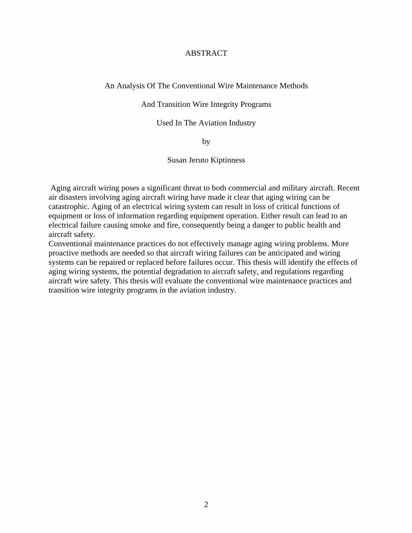
ABSTRACT
An Analysis Of The Conventional Wire Maintenance Methods
And Transition Wire Integrity Programs
Used In The Aviation Industry
by
Susan Jeruto Kiptinness
Aging aircraft wiring poses a significant threat to both commercial and military aircraft. Recent air disasters involving aging aircraft wiring have made it clear that aging wiring can be catastrophic. Aging of an electrical wiring system can result in loss of critical functions of equipment or loss of information regarding equipment operation. Either result can lead to an electrical failure causing smoke and fire, consequently being a danger to public health and aircraft safety. Conventional maintenance practices do not effectively manage aging wiring problems. More proactive methods are needed so that aircraft wiring failures can be anticipated and wiring systems can be repaired or replaced before failures occur. This thesis will identify the effects of aging wiring systems, the potential degradation to aircraft safety, and regulations regarding aircraft wire safety. This thesis will evaluate the conventional wire maintenance practices and transition wire integrity programs in the aviation industry.
2

Copyright 2004 by Susan J. Kiptinness
All Rights Reserved
3

DEDICATION
I would like to dedicate this work to my family who have supported me through the years and to
the Lord Jesus Christ, for His blessings and the strength to pursue my education.
“Delight yourself in the Lord
and He will give you the desires of your heart.”
(Psalm 37:4)
4
ACKNOWLEDGEMENTS
I would like to express sincere gratitude to Dr. Paul Sims, Chairman of my graduate committee,
for his assistance and guidance during the preparation of this thesis and during the course of my
study. Acknowledgement is also made to Dr. Andrew Clark and Mr. Hugh Broome for their
assistance in the preparation of this thesis. I would also like to thank Dr. Keith Johnson, Chair of
the Department of Technology, for his valuable assistance and counsel through the duration of
my studies.
Finally, I would like to express my sincere appreciation to my family and friends for their
continued support, prayers, and encouragement
5
CONTENTS
Page
ABSTRACT………………………………………………………………………... 2
LIST OF TABLES…………………………………………………………………. 10
LIST OF FIGURES………………………………………………………………… 11
Chapter
1. INTRODUCTION………………………………………………………….. 12
2. BACKGROUND OF AIRCRAFT WIRE SAFETY……………………….. 14
Analysis of Wire Type Effects………………………………………….. 20
PVC – Polyvinly Chloride/Nylon Insulation………………………... 20
Aromatic Polymide Wrapped Insulation……………………………. 20
XL-ETFE- Cross Linked Ethylene Tetra Fluoro Ethlyene………….. 21
Poly-X-Extruded Aliphatic Polymide……………………………….. 21
3. FEDERAL AVIATION ADMINISTRATION REGULATIONS REGARDING
AIRCRAFT WIRE SAFETY……………………………………………….. 25
Wiring Maintenance Practices…………………………………………... 25
Electrical Load Determination…………………………..................... 25
Circuit Breaker Protection…………………………………………… 25
Wire Selection……………………………………………………...... 26
Wire Routing……………………………………………………….... 27
Clamping……………………………………………………………... 29
6

Wire Bend Radii……………………………………………………... 32
Unused Connectors and Unused Wires……………………………... 33
Wire Replacement……………………………………………………. 35
Wire Splicing…………………………………………………………. 36
Wire Terminals………………………………………………………... 37
Grounding and Bonding…………………………………………….... 40
Grounding……………………………………………………... 40
Bonding………………………………………………………... 41
Wire Marking………………………………………………………….. 41
Conduits……………………………………………………………….. 42
Wire Insulation………………………………………………………… 43
Cleaning……………………………………………………………….. 45
4. CURRENT WIRE MAINTENANCE METHODS UTILIZED IN THE
AVIATION INDUSTRY...................................................................................... 46
Handheld…………………………………………………………………… 48
Brighton Electronics…………………………………………………… 50
Test Products International…………………………………………….. 50
B & K Precision……………………………………………………….. 51
Fluke Corporation……………………………………………………… 51
Kenwood TMI Corporation……………………………………………. 51
Time Domain Reflectometry………………………………………………. 52
Riser Bond Instruments………………………………………………… 54
Phoenix Aviation and Technology……………………………………… 55
7

Bicotest…………………………………………………………………. 55
Frequency Domain Reflectometry…………………………………………. 56
Standing Wave Reflectometry……………………………………………… 57
5. TRANSITION WIRE MAINTENANCE PROGRAMS……………………….. 61
Smart Wiring……………………………………………………………….. 61
Arc Fault Circuit Breakers………………………………………………….. 65
Nova………………………………………………………………………… 69
6. ANALYSIS OF THE CONVENTIONAL AND TRANSITION WIRE
MAINTENANCE METHODS.................................................................................. 74
Handheld Multimeter……………………………………………………….. 75
Time Domain Reflectometer……………………………………………….. 75
Frequency Domain Reflectometer………………………………………….. 75
Standing Wave Reflectometer………………………………………………. 76
Smart Wiring………………………………………………………………… 76
Arc Fault Circuit Breakers…………………………………………………… 77
Nova………………………………………………………………………….. 77
7. CONCLUSIONS AND RECOMMENDATIONS………………………………. 81
Conclusions………………………………………………………………….. 81
Aircraft Wiring Ages and Deteriorates Over Time……………………… 81
Aging Wiring Severely Impacts Aircraft Safety………………………… 82
Current Maintenance Programs do Not Effectively Address Aircraft
Wiring…………………………………………………………………… 82
Recommendations…………………………………………………………… 83
8
Incorporate Proactive Wire Maintenance Programs…………………….. 83
Enhance Collaboration among Industry, Academia and the
Government……………………………………………………………. 83
Improve the Management and Functionality of Wire
Systems………………………………………………………………… 83
Support Training……………………………………………………….. 84
REFERENCES…………………………………………………………………………. 85
APPENDICES………………………………………………………………………….. 91
Appendix A: Acronyms………………………………………………………… 91
Appendix B: Glossary………………………………………………………….. 93
Appendix C: Aircraft Wire Table……………………………………………….. 95
VITA…………………………………………………………………………………….. 103
9

LIST OF TABLES
Table Page
1. Incidents Involving Electrical Problems……………….…………………….. 15
2. ATSRAC Sample Aircraft Data……………………………………………… 20
3. Comparative Properties of Wire Insulation Systems…………………………. 44
4. Wiring Problems, Indicators and Detection Methods………………………… 47
5. Characteristics of Multimeters and Manufacturers…………………………… 52
6. Features, Advantages and Benefits of Smart Wiring…………………………. 65
7. Advanced Nova Test Capabilities……………………………………………... 73
8. Analysis Between Conventional and Transition Wire Maintenance Programs... 79
10

LIST OF FIGURES
Figure Page
1. TWA Flight 800: The Reconstruction………………………………………… 17
2. FAA Aging Systems Program Chronology…………………………………… 19
3. Wires Riding on Structure…………………………………………………….. 28
4. Wires Improperly Routed……………………………………………………... 29
5. Typical Rubber Clamp………………………………………………………… 31
6. Clamping……………………………………………………………………….. 32
7. Minimum Bend Radii………………………………………………………….. 33
8. Spare Wire Termination Using Endcap……………………………………….. 34
9. Coil and Stow Methods……………………………………………………….. 34
10. Adding or Replacing Wires on a Bundle……………………………………… 36
11. Staggered Splices……………………………………………………………… 37
12. Terminal Stacking Like materials…………………………………………….. 39
13. Terminal Stacking Unlike materials………………………………………….. 39
14. BK 5380 Digital Multimeter…………………………………………………… 49
15. BK 114B Analog Multimeter………………………………………………….. 49
16. Types of Time Domain Reflectometers……………………………………….. 54
17. Standing Wave Reflectometer…………………………………………………. 59
18. Smart Wiring Technology Subcomponents……………………………………. 63
19. Eaton Arc Fault Circuit Breakers………………………………………………. 67
20. Troubleshooting Time Costs for an Average Narrow Body Aircraft…………… 72
11

CHAPTER 1
INTRODUCTION
As today’s commercial and military aircraft age, so do the hundreds of miles of plastic
coated and cloth coated wiring responsible for delivering such critical systems as power and
communications in each airplane. Electrical wire in aircraft has become a critical and vital
component as aircraft performance and actual flight stability become dependent on avionics
(Kuzniar & Slenski, 2002).
Aircraft wiring not only distributes electrical power but provides control and information
links between multiple systems and sub-systems. The components that make-up the wiring
system include power and control conductors, signal and instrumentation conductors, fiber optic
cables, connectors, circuit breakers, relays, power distribution and control panels, and generators.
Failure of any of these components can disable an aircraft or compromise an aircrew’s ability to
control the aircraft (Kuzniar & Slenski, 2000).
Because of the explosion and crash of TWA flight 800 off Long Island, New York in
1996 and the crash of Swissair flight 111 off Nova Scotia, Canada in 1998, a Wire System Safety
Interagency Working Group was formed in June 2000 to examine aircraft wiring problems. Their
report titled, “Review of Federal Programs for Wire System Safety” published in November
2000, emphasized the importance of aircraft wiring systems and concern of their aging (Lane,
2000).
All wiring systems are subject to aging during their normal service life. Aged wiring is
defined as “wire exhibiting degraded performance due to accumulated damage from long-term
exposure to chemical, thermal, electrical and mechanical stresses (D’Angelo, Decker, Dicks,
Johnson, & White, 2001).” As an example, a build up of damage to the wiring results from
12

installation and operational stresses and maintenance practices. Aircraft wiring is subject to more
rapid deterioration with age in areas of high fluid contamination, vibration, temperature
variation, and where it is attached to parts that are moved or removed often (D’Angelo et al.,
2001).
As aircraft age, wiring becomes more difficult to maintain with traditional methods.
Many of the current maintenance approaches are reactive and only address wiring when a failure
cannot be resolved. Inspection and troubleshooting methods presently utilized by maintenance
personnel are limited to visual inspection. Visual inspection of individual wires in a bundle or
connector is not a practical method because as wire ages it becomes stiff and dismantling the
bundle or connector may introduce collateral damage resulting in safety hazards. In addition,
wiring may also be difficult to inspect in various parts of an aircraft due to the inaccessibility, for
example, wiring inside conduits and behind panels or equipment (D’Angelo et al., 2001).
More proactive methods are needed so that aircraft wiring failures can be anticipated and
wiring systems can be repaired or replaced during scheduled maintenance activities. There are
numerous techniques employed in the aviation field by maintenance technicians. New
technologies are being developed to facilitate inspection and detection of wire defects before
they affect electrical system operation and improve overall wire system integrity. Among the
most promising technologies are advanced reflectometry methods, smart wire systems, and arc
fault circuit breakers. Remaining challenges include identifying the miniature insulation breaks
by means of impedance/spectroscopy technology and radio frequency leak test methods. This
thesis seeks to identify the aging wiring problem in aircraft, highlight some of the current wire
maintenance practices used in the aviation industry, and analyze advanced technologies being
developed to combat the aging wiring problem.
13

CHAPTER 2
BACKGROUND OF AIRCRAFT WIRE SAFETY
As the aircraft fleet ages, the challenge for the aviation community is to maintain a high
standard of safety in an economic environment that is intensely competitive. The Federal
Aviation Administration (FAA), in partnership with the aviation community, is leading the way
in ensuring the safety of the commercial fleet (Smith, 2002).
The FAA and the National Transportation Safety Board (NTSB) have reported hundreds
of potential hazardous incidents of smoke and electrical problems in aircraft cabins and cockpits.
Table 1 lists a few examples of incidents involving electrical problems (Brown & Gau, 2001).
14

Table 1
Incidents Involving Electrical Problems (Brown, & Gau, 2001)
DATE AIRLINE/
AIRCRAFT TYPE
PROBLEM WIRE FAILURE DUE TO:
RESOLUTION
12/2000 Delta Airlines 219, L-1011
Electrical fire due to arcing of the windshield heat wire bundle
Arcing of aircraft structure, Adel clamp & a 30-wire bundle
NTSB investigation of this incident is ongoing
11/2000 Air Tran 956, DC-9-32
Electrical fire to the left forward areas of the fuselage & cargo compartment from fuselage stations (FS) 237-313 & damage to cabin floor.
Arcing and damaged wiring around FS 237 and pin-pin shorts of electrical connectors
NTSB recommends FAA to require all DC-9 operators to visually inspect electrical connectors at FS 237 for evidence of lavatory rinse fluid contamination & for presence of a drip shield above disconnect panel in accordance with Boeing Alert Service Bulletin DC9-24A190
11/2000 American Airlines 1683, MD-80
Electrical fire in the aircraft wiring above the cabin ceiling panels
Lightning strike caused arcing in the aircraft’s wiring
NTSB investigation of this incident is ongoing
10/2000 Continental Airlines flight 1579
Electrical fire in the left jump seat area near the registration certificate holder
Several heavy gauge electrical wires severed and welded together on the opposite side of the jump seat wall
Corrective actions that Continental Airlines have taken are to remove all certificate holders on EPC wall & install new 3-slot certificate holder on galley wall -has honeycomb backing.
8/2000 Air Tran Flight 913, DC-9
Smoke due to electrical arcing in the bulkhead behind captain’s seat
Arcing ignited interior panels
NTSB recommends FAA to equip interior panels with access panels/ports to apply extinguishing agent behind interior panels
9/99 Delta Airlines 2030, MD-88
Smoke in cabin due to smoldering insulation blanket
Arcing from the static port heater ignited the insulation blanket & became a self -sustaining fire
NTSB issued FAA recommendations contained in A-01-003, A-01-004 & A-01-005
15
Swiss Air Flight 111 and TWA Flight 800 are examples of two high profile fatal crashes
that resulted from faulty electrical wiring. On September 2nd 1998, Swiss Air Flight 111, an MD-
11 aircraft crashed off the coast of Nova Scotia in Canada. The aircraft en route from John F.
Kennedy (JFK) International Airport, New York to Geneva, Switzerland, crashed into the North
Atlantic killing all 215 passengers and 14 crewmembers. According to the Canadian
Transportation Safety Board (TSB): final accident report number A98H0003 dated March 27th
2003, the in flight fire “most likely started from an electrical arcing event that occurred above the
ceiling on the right side of the cockpit near the cockpit rear wall (Fiorino, 2003).” The arcing of
one or more wires in turn ignited the inflammable cover material on nearby thermal acoustic
insulation blankets and quickly spread. A segment of electrical cable from the in flight
entertainment network is believed to be associated with one or more of the arcing events
(Fiorino, 2003).
On July 17th 1996, Trans World Airlines (TWA) Flight 800, a Boeing 747-131, crashed
in the Atlantic Ocean near East Moriches, New York. The flight was operating as a scheduled
international passenger flight from John F. Kennedy (JFK) International Airport New York to
Paris, France. All 212 passengers and 18 crewmembers were killed and the airplane was
destroyed. According to the National Transportation Board (NTSB): final accident report number
NTSB/AAR-00/03 dated August 23rd 2000, it was determined that the probable cause of this
accident was an explosion of the center wing fuel tank (CWT) resulting from ignition of the
inflammable fuel/air mixture in the tank. The source of the ignition energy for the explosion
could not be determined with certainty, but, of the sources evaluated by the investigation, the
most likely source was a short circuit outside of the center fuel tank that allowed excessive
voltage to enter it through electrical wiring associated with the fuel quantity indication system.
16
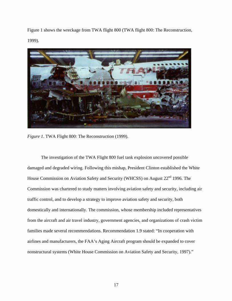
Figure 1 shows the wreckage from TWA flight 800 (TWA flight 800: The Reconstruction,
1999).
Figure 1. TWA Flight 800: The Reconstruction (1999).
The investigation of the TWA Flight 800 fuel tank explosion uncovered possible
damaged and degraded wiring. Following this mishap, President Clinton established the White
House Commission on Aviation Safety and Security (WHCSS) on August 22nd 1996. The
Commission was chartered to study matters involving aviation safety and security, including air
traffic control, and to develop a strategy to improve aviation safety and security, both
domestically and internationally. The commission, whose membership included representatives
from the aircraft and air travel industry, government agencies, and organizations of crash victim
families made several recommendations. Recommendation 1.9 stated: “In cooperation with
airlines and manufacturers, the FAA’s Aging Aircraft program should be expanded to cover
nonstructural systems (White House Commission on Aviation Safety and Security, 1997).”
17
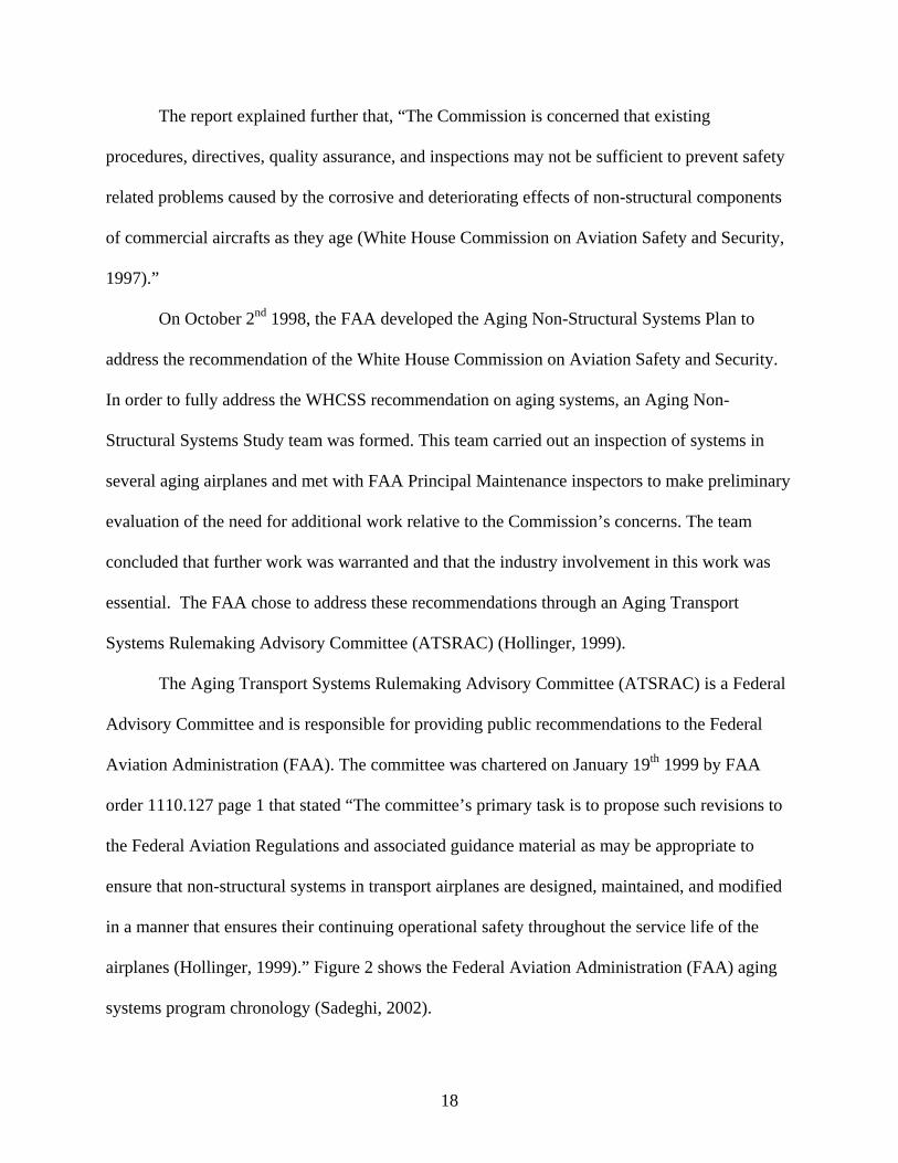
The report explained further that, “The Commission is concerned that existing
procedures, directives, quality assurance, and inspections may not be sufficient to prevent safety
related problems caused by the corrosive and deteriorating effects of non-structural components
of commercial aircrafts as they age (White House Commission on Aviation Safety and Security,
1997).”
On October 2nd 1998, the FAA developed the Aging Non-Structural Systems Plan to
address the recommendation of the White House Commission on Aviation Safety and Security.
In order to fully address the WHCSS recommendation on aging systems, an Aging Non-
Structural Systems Study team was formed. This team carried out an inspection of systems in
several aging airplanes and met with FAA Principal Maintenance inspectors to make preliminary
evaluation of the need for additional work relative to the Commission’s concerns. The team
concluded that further work was warranted and that the industry involvement in this work was
essential. The FAA chose to address these recommendations through an Aging Transport
Systems Rulemaking Advisory Committee (ATSRAC) (Hollinger, 1999).
The Aging Transport Systems Rulemaking Advisory Committee (ATSRAC) is a Federal
Advisory Committee and is responsible for providing public recommendations to the Federal
Aviation Administration (FAA). The committee was chartered on January 19th 1999 by FAA
order 1110.127 page 1 that stated “The committee’s primary task is to propose such revisions to
the Federal Aviation Regulations and associated guidance material as may be appropriate to
ensure that non-structural systems in transport airplanes are designed, maintained, and modified
in a manner that ensures their continuing operational safety throughout the service life of the
airplanes (Hollinger, 1999).” Figure 2 shows the Federal Aviation Administration (FAA) aging
systems program chronology (Sadeghi, 2002).
18
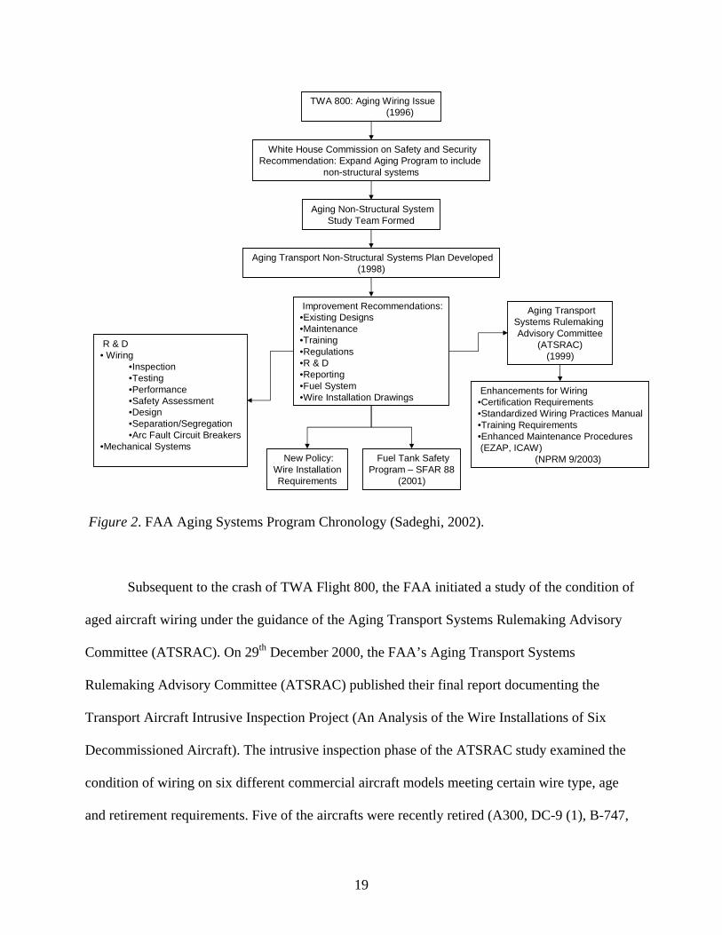
TWA 800: Aging Wiring Issue(1996)
Aging TransportSystems Rulemaking Advisory Committee
(ATSRAC)(1999)
White House Commission on Safety and SecurityRecommendation: Expand Aging Program to include
non-structural systems
Aging Non-Structural SystemStudy Team Formed
Aging Transport Non-Structural Systems Plan Developed(1998)
Improvement Recommendations:•Existing Designs•Maintenance•Training•Regulations•R & D•Reporting•Fuel System•Wire Installation Drawings
Enhancements for Wiring•Certification Requirements•Standardized Wiring Practices Manual•Training Requirements•Enhanced Maintenance Procedures(EZAP, ICAW)
(NPRM 9/2003)New Policy:Wire InstallationRequirements
Fuel Tank SafetyProgram – SFAR 88
(2001)
R & D• Wiring
•Inspection•Testing•Performance•Safety Assessment•Design•Separation/Segregation•Arc Fault Circuit Breakers
•Mechanical Systems
Figure 2. FAA Aging Systems Program Chronology (Sadeghi, 2002).
Subsequent to the crash of TWA Flight 800, the FAA initiated a study of the condition of
aged aircraft wiring under the guidance of the Aging Transport Systems Rulemaking Advisory
Committee (ATSRAC). On 29th December 2000, the FAA’s Aging Transport Systems
Rulemaking Advisory Committee (ATSRAC) published their final report documenting the
Transport Aircraft Intrusive Inspection Project (An Analysis of the Wire Installations of Six
Decommissioned Aircraft). The intrusive inspection phase of the ATSRAC study examined the
condition of wiring on six different commercial aircraft models meeting certain wire type, age
and retirement requirements. Five of the aircrafts were recently retired (A300, DC-9 (1), B-747,
19

L1011, DC-9 (2)) and one was decommissioned but not retired (DC-10). These aircraft are
shown in Table 2 (Smith, 2002).
Table 2
ATSRAC Sample Aircraft Data (Smith, 2002) ∗ See Appendix C
Aircraft Sampled A300 DC-9 B-747 DC-9 L1011 DC-10
Inspection 9/99 12/99 2/00 5/00 6/00 6/00
Year Mfr 1978 1967 1973 1971 1972 1979
Hours 39,713 74,558 100,241 66,801 63,618 61,334
Cycles 27,078 100,017 20,348 75,446 26,256 18,818
Retired 7/99 9/99 5/99 12/99 6/99 5/003
Wire Type∗ Polyimide PVC/G/N Poly-X PVC/G/N Polyimide XL-ETFE
Analysis of Wire Type Effects
PVC – Polyvinly Chloride/Nylon Insulation
For the two aircraft, the vast majority of the wire degenerative conditions and especially
the cracked insulation conditions seemed indicative of the low hydro-retention and thermal
performance of the insulation material and particularly of the polyamide (nylon). Comparison of
the data for the two DC-9 aircraft with PVC/Glass/Nylon (especially the heat damage data)
showed that other factors other than wire type have a major effect on the state of the wire (Smith,
2000).
Aromatic Polymide Wrapped Insulation
The degenerative condition data for this wire wrapped insulation showed relatively low
levels of vibration and chafing damage conditions, indicative of this insulations good mechanical
performance. The Aircraft data showed a wide variation between the two aromatic polymide
aircraft inspected in regard to cracking reported. The L1011 exhibited significantly more
20

cracking. The inspection data showed topcoat damage on both the A300 and L1011 aircrafts
(Smith, 2000).
XL-ETFE – Cross-Linked Ethylene Tetra Flouro Ethylene
The cross-linked ETFE data showed that the aircraft thermal, fluid, and chemical
contamination environments did not adversely influence the aging characteristics of this
insulation. The results of the insulation resistance test and the dielectric withstand voltage test
done in the Sandia and Raytheon laboratories confirmed that there was little change in the
insulative properties of the ETFE material as a result of exposure to these environments (Smith,
2000).
Poly- X- Extruded Aliphatic Polymide
This wire insulation displayed characteristic radial cracking mode. This was later verified
with Sandia Laboratory testing. There was evidence of arcing found as well (Smith, 2000).
The inspections of the ATSRAC study involved three distinctive tasks:
1. Detailed visual inspection with or without invasive follow-up
2. Nondestructive testing (NDT)
3. Laboratory analysis
The data from the visual inspections, nondestructive testing, and laboratory analysis were
analyzed to accomplish two objectives:
a. To evaluate the adequacy of visual inspection for detecting deteriorating wire
installations.
b. To determine the condition of wire in aged aircraft
The intrusive inspection focused on six significant categories of wire degradation:
i. Degraded wire repairs or splices
21
ii. Heat damaged or burnt wire
iii. Vibration damage or chafing
iv. Cracked insulation
v. Arcing
vi. Insulation delamination (Smith, 2000).
The visual inspections completed during the intrusive inspection phase of the ATSRAC study
were more detailed than the visual inspection procedures normally followed as a part of routine
aircraft maintenance. After completion of the detailed visual inspection, nondestructive testing
(NDT) was carried out on the aircraft before wire bundle samples were removed for laboratory
analysis. The two methods of nondestructive testing used were the Lectromechanical Design
Company’s Del Test and Eclypse testing (D’Angelo et al., 2001).
Nondestructive testing (NDT) was done to locate insulation damage, which may include cuts,
cracks, splices or abrasions, conductor shorts, and opens. When the wire bundles arrived in the
laboratory for detailed analysis of individual wires, they were tested once more for insulation
damage. The core conductor from each wire specimen was also removed for further examination.
Laboratory testing on randomly selected wire was performed at both Sandia National Labs and
Raytheon. Nondestructive testing (NDT) was primarily used to verify all defects had been
identified during visual inspection and to make certain that the process of removing the samples
from the aircraft had not induced new damage. Results of the nondestructive testing (NDT) done
on the wire bundles before aircraft removal and laboratory analysis exposed a number of
significant defects that had gone unidentified using the intensive detailed visual inspection
method. These results indicate visual inspection is least effective in finding defects in aircraft
wiring as compared to automated or instrumented inspection techniques (Smith, 2000).
22
Using visual inspection as the key wire management tool raises some concern especially due
to the large amount of contamination on the wiring inspected during the intrusive inspection
phase of the ATSRAC study. The accumulation had probably taken place over a number of
years. Accumulation of fluid contaminants (e.g. water waste, hydraulic) and solid debris (e.g.
drill shavings, foreign objects) on/in many wire bundles in each of the aircrafts studied was quite
extensive, making it impossible to visually inspect them (Smith, 2000).
General visual inspection is a technique used to inspect the condition of both commercial and
military aircraft wiring on an ongoing basis and to deal with aging mechanisms and damage
resulting from normal operation and maintenance. The nondestructive testing (NDT) and
laboratory analysis done during the ATSRAC study showed more wire damage than the general
visual inspection; therefore, it can be assumed that several wiring defects go undetected during
normal maintenance operations. In most cases, these wire defects are found only after system
failures, insulation charring, smoke, or electrical fire has taken place (D’Angelo et al., 2001).
Results from the intrusive inspection ATSRAC study illustrated that visual inspection can be
effective in identifying certain conditions:
a. Heat damaged or burnt wire
b. Vibration damage or chafing
Some examples of conditions that may be visually undetectable are:
a. Cracked insulation
b. Arcing
c. Insulation delamination
d. Degraded repairs or splices
e. Damage and degradation hidden under accumulated lint or other contaminants
23
f. Damage inside protective wrap materials, conduit or in inaccessible areas
g. Damage or degradation hidden inside wire bundles (Smith, 2000).
General visual inspection techniques limit the extent to which aircraft wire damage and
degradation can be detected, hence the need for more wire diagnostic equipment
(automated/instrumented). If aircraft safety is to be enhanced, inspection methods must be able
to identify precursors before defects become visually evident causing charring, smoke, and/or
electrical fires.
24

CHAPTER 3
FEDERAL AVIATION ADMINISTRATION REGULATIONS
REGARDING AIRCRAFT WIRE SAFETY
Historically, aircraft wiring was installed and treated as a “fit and forget” commodity rather
than as an indispensable system. While there is a tendency to ignore wire systems, there is a need
to manage aging wire systems so that they continue to function safely. The government has
developed regulations, codes, and standards for aircraft safety. Both the aviation industry and
government have developed operational practices that focus on maintaining the integrity of the
aircraft wiring system (Brown & Gau, 2001).
Wiring Maintenance Practices
Electrical Load Determination
Electrical load determination ensures each aircraft electrical bus can safely sustain a
predetermined amount of load, which is based on the electrical capacity of the aircraft’s overall
electrical distribution system. The load analysis is determined to make sure that all electrical
devices can be safely controlled or managed by the aircraft’s electrical system (Aircraft Wiring
Practices, 2002).
When adding an electrical device, a load analysis should be carried out to ensure that the new
load on the bus can be powered effectively and that there is adequate electrical power margin to
avoid overloading the bus (Federal Aviation Administration, 1998).
Circuit Breaker Protection
All electrical wires must have some means of circuit protection. Electrical wire should be
protected with circuit breakers or fuses positioned as close as possible to the electrical power
source. The manufacturer of electrical equipment will generally specify the fuse or breaker to be
25

used when installing the respective equipment. In addition, SAE ARP 1199 may also be referred
to for recommendation practices (Federal Aviation Administration, 1998).
According to FAA Advisory Circular (AC) 25.1357, automatic protective devices should be
used to minimize distress to the electrical system and hazards to the airplane, in the event of
wiring faults or serious malfunction of the system or connected equipment. Circuit breakers are
designed as circuit protection for the aircraft wiring and not for protection of black boxes or
other components. A circuit breaker is rated so that it will open before the current rating of the
wire attached to it is exceeded or before the cumulative rating of all loads connecting to it are
exceeded, whichever is lowest (Federal Aviation Administration, 1998).
FAA Advisory Circular (AC) 25-16 states that crews should not attempt to reset a circuit
protection device in flight. For the reason that resetting the circuit breaker can greatly influence
the degree of arcing damage to the aircraft wiring. Each successive attempt to restore an
automatically disconnected circuit protection device, can lead to progressively worsening effects
from arcing. Use of a circuit breaker as a switch is not recommended because it reduces the life
of the circuit breaker.
Wire Selection
Aircraft service imposes severe environmental conditions on electrical wire; for that reason,
selecting the correct wire is critical to the performance of the aircraft. Wires should be sized so
that they accomplish the following:
1. Have sufficient mechanical strength to allow for service condition
2. Do not exceed allowable voltage drop levels
3. Are protected by circuit protection devices
4. Meet circuit current carrying requirements
26
In general, wires smaller than size number 20 should be provided with additional support at
terminations, such as strain relief cramps, connector grommets, shrinkable sleeving or
telescoping bushings. Additionally, they should not be used in areas of excessive vibration,
repeated bending or frequent disconnection from screw termination. When determining the
current capacity of the aircraft wires, the following factors should be considered (Federal
Aviation Administration, 1998):
1. Effects of heat aging on wire insulation
2. Maximum operating temperature
3. Single wire or wires in a harness
4. Altitude
Bare copper develops a surface oxide coating at a rate dependent on temperature. This oxide
film is a poor conductor of electricity and impedes wire determination. Consequently, all aircraft
wiring has a coating of tin, silver, or nickel that have far slower oxidation rates.
1. Tin coated copper: < 150° C
2. Silver coated wire: < 150° C
3. Nickel coated wire: < 260° C
When a replacement wire is needed the maintenance manual for the aircraft must first be
reviewed to verify if the Original Aircraft Manufacturer (OAM) has approved any substitution. If
there is no substitute, then the original aircraft manufacturer must be contacted for acceptable
replacement (Federal Aviation Administration, 1998).
Wire Routing
All aircraft wiring should be installed so that it is mechanically and electrically sound and
neat in appearance. FAA Advisory Circular (AC) 65 states, “Wires and bundles should be routed
27
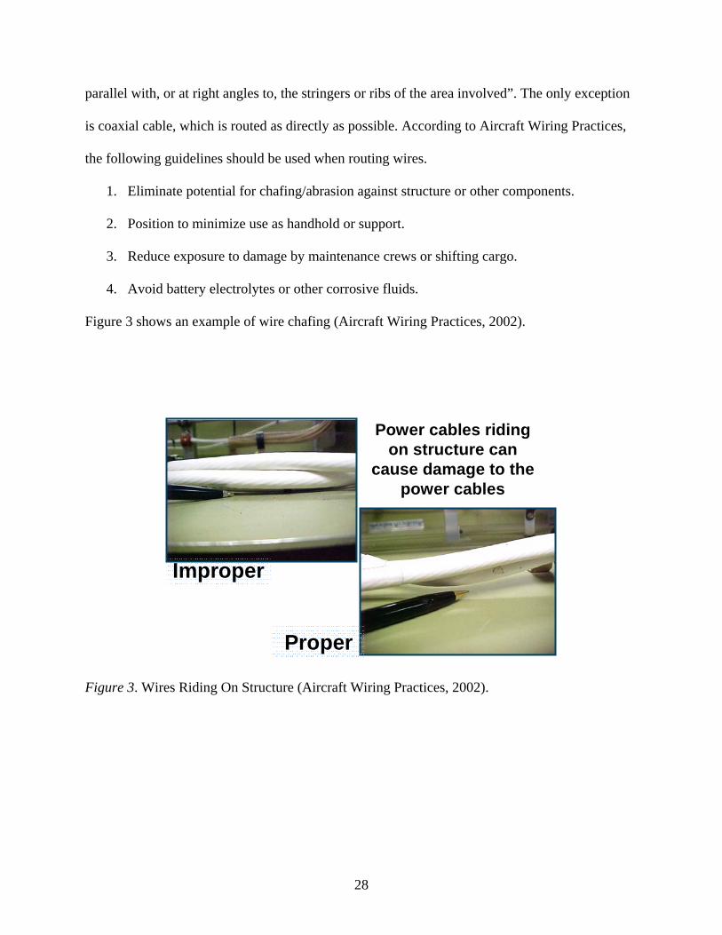
parallel with, or at right angles to, the stringers or ribs of the area involved”. The only exception
is coaxial cable, which is routed as directly as possible. According to Aircraft Wiring Practices,
the following guidelines should be used when routing wires.
1. Eliminate potential for chafing/abrasion against structure or other components.
2. Position to minimize use as handhold or support.
3. Reduce exposure to damage by maintenance crews or shifting cargo.
4. Avoid battery electrolytes or other corrosive fluids.
Figure 3 shows an example of wire chafing (Aircraft Wiring Practices, 2002).
Power cables riding on structure can
cause damage to the power cables
Improper
Proper
Figure 3. Wires Riding On Structure (Aircraft Wiring Practices, 2002).
28

Figure 4 shows wires in a bundle not properly routed (Aircraft Wiring Practices, 2002)
Wires improperly tied, riding on hydraulic lines,
contaminated with caustic fluid
Figure 4. Wires Improperly Routed (Aircraft Wiring Practices, 2002).
Clamping
Clamps and other primary support devices should be made of materials that are compatible
with their installation and environment, which is temperature, fluid résistance, exposure to
ultraviolet light, and wire bundle mechanical loads. Clamps should be spaced at intervals not
exceeding 24 inches. Clamping intervals may need to be decreased in high vibration areas or
areas around structural intrusions in order to provide support. FAA Advisory Circular (AC)
43.13-1b mandates these guidelines:
1. Clamps on wire bundles should not allow the movement of the bundle through the clamp
when a slight axial pull is applied.
29
2. Clamps on RF cables should have a snug fit to inhibit the cable from moving freely
through the clamp but still allow for cable movement through the clamp when a light
axial pull is applied.
3. Plastic clamps or cable ties should not be used where their failure could result in
interference with movable controls, wire bundle contact with moveable equipment, or
chafing damage to essential or unprotected wiring.
4. Clamps should be installed with their attachment hardware located above them.
Clamps lined with nonmetallic material should be used to support the wire bundle along the
run. Tying may be used between clamps but nonetheless it should not be regarded as a substitute
for adequate clamping. Adhesive tapes are prone to age deterioration and are not acceptable as a
clamping means.
Clamp pinching is a frequent problem in aircraft wiring. This takes places when there is too
much wiring in a clamp or when the clamp is not properly installed. To solve this problem,
clamps on wire bundles should be chosen to have a snug fit without pinching wires (Aircraft
Wiring Practices, 2002).
30

Figure 5 illustrates a typical rubber clamp (Aircraft Wiring Practices, 2002).
Stand offNo
pinching
Clamp tabs
Rubber cushion
Wedge
All wires contained in rubber cushion
Figure 5. Typical Rubber Clamp (Aircraft Wiring Practices, 2002).
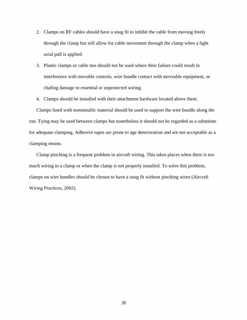
Figure 6 shows the correct method for clamping wires (Aircraft Wiring Practices, 2002).
31
Improper
Proper
Figure 6. Clamping (Aircraft Wiring Practices, 2002).
Wire Bend Radii
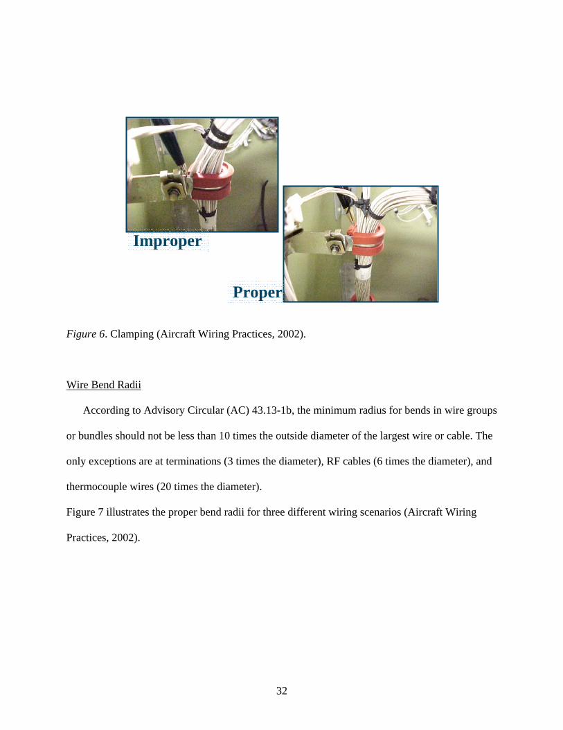
According to Advisory Circular (AC) 43.13-1b, the minimum radius for bends in wire groups
or bundles should not be less than 10 times the outside diameter of the largest wire or cable. The
only exceptions are at terminations (3 times the diameter), RF cables (6 times the diameter), and
thermocouple wires (20 times the diameter).
Figure 7 illustrates the proper bend radii for three different wiring scenarios (Aircraft Wiring
Practices, 2002).
32
No support at end of bend
Min. bend radius - 10 x parameter of wire or cable
Support at both ends of wire bend
Diameter of wire or cable
Min. bend radius 3 x diameter of wire
Figure 7. Minimum Bend Radii (Aircraft Wiring Practices, 2002).
Unused Connectors and Unused Wires
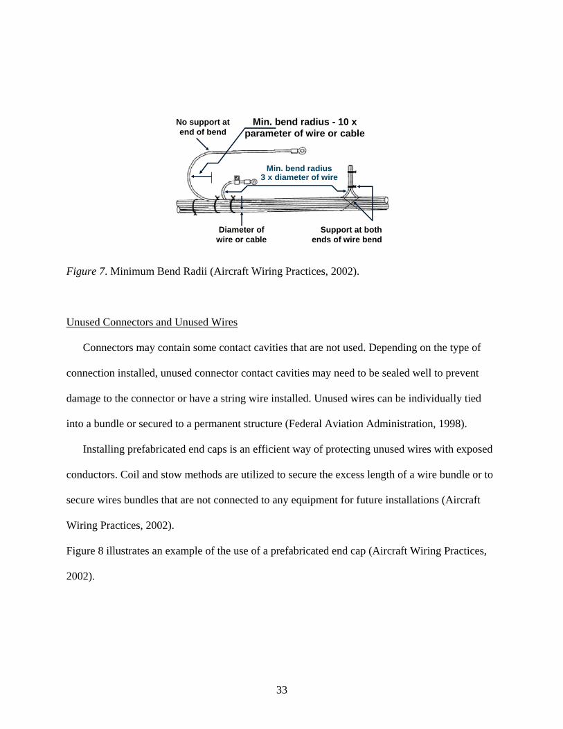
Connectors may contain some contact cavities that are not used. Depending on the type of
connection installed, unused connector contact cavities may need to be sealed well to prevent
damage to the connector or have a string wire installed. Unused wires can be individually tied
into a bundle or secured to a permanent structure (Federal Aviation Administration, 1998).
Installing prefabricated end caps is an efficient way of protecting unused wires with exposed
conductors. Coil and stow methods are utilized to secure the excess length of a wire bundle or to
secure wires bundles that are not connected to any equipment for future installations (Aircraft
Wiring Practices, 2002).
Figure 8 illustrates an example of the use of a prefabricated end cap (Aircraft Wiring Practices,
2002).
33

Wire and end cap in position
Install end cap over wire end. Shrink in place.
Fiberglass tying tape
Wire bundle
End caps
Adhesive tape
Figure 8. Spare Wire Termination Using Endcap (Aircraft Wiring Practices, 2002).
Figure 9 shows coil and stow methods used to secure wire bundles (Aircraft Wiring Practices,
2002).
Wire bundle
ties
Coil and stow short/long wire bundles in low vibration areas
Clamp
Wire bundle
Figure 9. Coil and Stow Methods (Aircraft Wiring Practices, 2002).
34
Wire Replacement
FAA Advisory Circular (AC) 43.13-1b requires aircraft wiring to be replaced with equivalent
wire when any of the following defects are located:
1. Wiring that has been subjected to chafing or fraying.
2. Wiring that show evidence of cracked outer insulation when slight flexing is applied.
3. Wiring that has weather cracked outer insulation.
4. Wiring that may have been exposed to electrolyte or on which the insulation appears to
be deteriorating due to the effects of electrolyte.
5. Wiring that shows visible evidence of having been crushed or kinked.
6. Shielded wiring on which the metallic shield is frayed or corroded.
7. Wiring exhibiting evidence of breaks, cracks, dirt, or moisture in the plastic sleeving.
8. Wiring that has its insulation saturated with engine oil, hydraulic fluid, or another
lubricant.
9. Sections of wire that have splices occurring at less than 10 ft intervals unless specifically
authorized.
Wires that are added or replaced on a wire bundle should be routed in the same way as the other
wires in the wire bundle.
Figure 10 illustrates the correct procedure for wire replacement (Aircraft Wiring Practices,
2002).
35

Correct procedure
Incorrect procedure
Chafing
Figure 10. Adding or Replacing Wires on a Bundle (Aircraft Wiring Practices, 2002).
Wire Splicing
Splicing is acceptable on aircraft wiring as long as it does not have an effect on the reliability
and the electro-mechanical characteristics of the wiring. Splicing of power wires, coaxial cables,
multiplex bus, and large gauge wire should be avoided. The only exception is if the wire splicing
has approved data. FAA Advisory Circular (AC) 43.13-1b mandates the following guidelines
when splicing wire:
1. Keep splicing to the minimum.
2. Avoid splicing wires in high vibration areas.
3. Splicing in bundles should be staggered to minimize any increase in the size of the
bundle.
36

4. Splicing of individual wires should have engineering approval and the splice should
allow for periodic inspection.
5. Use a self-insulated splice connector if possible. Nevertheless, if a non-insulated splice
connector is used the splice should be covered with plastic sleeving that is secured at both
ends.
6. Environmentally sealed splices that conform to MIL-L-7928 are reliable in SWAMP
(Severe Wind and Moisture Problems) areas. However, if a non-insulated splice is to be
used, the splice should be covered with dual wall shrink sleeving of a suitable material
(AC 43.13-1b).
Figure 11 shows the use of staggered splices in wire bundles (Aircraft Wiring Practices, 2002).
Figure 11. Staggered Splices (Aircraft Wiring Practices, 2002).
Wire Terminals
Terminals are connected to the ends of electrical wires to facilitate connection of the wires to
terminal strips or items of equipment. The tensile strength of the wire-to-terminal joint should be
at least equal to the tensile strength of the wire itself. The resistance of the wire-to-terminal joint
should be small relative to the normal resistance of the wire. According to FAA Advisory
Circular (AC) 43.13-1b, the following factors should be considered when selecting wire
terminals:
1. Current rating
37

2. Wire size (gauge) and insulation diameter
3. Conductor material compatibility
4. Stud size
5. Insulation material compatibility
6. Application environment
A terminal strip is fitted with barriers to prevent the terminals on adjacent studs from
contacting each other. Terminal strips should be inspected for loose connections, metallic objects
that may have fallen across the terminal strip, dirt and grease accumulation. Such conditions can
cause arcing, which may lead to a fire or system failures.
Terminal lugs should be used to connect wiring to terminal block studs or equipment
terminal studs. The maximum number of terminal lugs and a bus to be connected to any one stud
is four and three respectively. Terminal lugs should be chosen with a stud hole diameter that
matches the diameter of the stud. In instances where there is a variation in the diameter of the
terminal lugs attached to a stud, the greatest diameter should be placed on the bottom and the
smallest diameter on the top (Federal Aviation Administration, 1998).
Terminals that are made of like materials can be stacked directly on top of each other. On the
other hand, terminals that are made of unlike materials, for example aluminum and copper a
cadmium-plated flat washer is used to isolate the dissimilar metals. A terminal that is completely
assembled should have a minimum of two to three threads showing on the stud when the nut is
torqued properly.
Figures12 and 13 illustrate terminal stacking materials and methods (Aircraft Wiring Practices,
2002).
38

Flat washer
Lock washer
Nut
Terminal stud
Copper terminal lugs
Figure 12. Terminal Stacking Like Materials (Aircraft Wiring Practices, 2002).
Copper terminal
Flat washer
Lock washer
Terminal stud
Nut
Aluminum terminalsFlat
washers
Figure 13. Terminal Stacking Unlike Materials (Aircraft Wiring Practices, 2002).
39
Grounding and Bonding
Grounding. Grounding is defined as the “process of electrically connecting conductive
objects to either a conductive structure or some other conductive return path for the purpose of
safely completing either a normal or fault circuit (Federal Aviation Administration, 1998).”
According to Advisory Circular (AC) 65-15A, bonding and grounding connections are made in
aircraft electrical systems to accomplish the following:
a. Protect aircraft and personnel against hazards from lightning discharge.
b. Provide current return paths.
c. Prevent development of radio-frequency potentials.
d. Protect personnel from shock hazards.
e. Provide stability of radio transmission and reception.
f. Prevent accumulation of static charge.
Advisory Circular 65-15A recommends the following general procedures and precautions when
making bonding or grounding connections.
a. Bond or ground parts to the primary aircraft structure where possible.
b. Make bonding or grounding connections so that no part of the aircraft
structure is weakened.
c. Bond parts individually if feasible.
d. Install bonding or grounding connections against smooth, clean surfaces.
e. Install bonding or grounding connections so that vibration, expansion or
contraction, or relative movement in normal service will not break or loosen
the connection.
40
Bonding. Bonding refers to the “electrical connecting of two or more conducting objects not
otherwise adequately connected (Advisory Circular 65-15A).” FAA Advisory Circular (AC)
43.13-1b mandates the following bonding specifications:
1. Equipment Bonding
Low impedance paths to aircraft structure are generally required for electronic
equipment to provide radio frequency return circuits and to facilitate reduction in
electromagnetic interference.
2. Metallic Surface Bonding
All conducting objects located on the exterior of the airframe should be
electrically connected to the airframe through mechanical joints, conductive
hinges, or bond straps, which are capable of conducting static charges and
lightning strikes.
3. Static Bonds
All isolated conducting paths inside and outside the aircraft with an area greater
than 3 in² and a linear dimension over 3 inches that are subjected to electrostatic
charging should have a mechanically secure electrical connection to the aircraft
structure of adequate conductivity to dissipate possible static charges.
Wire Marking
Correct identification of electrical wires and cables with their circuits and voltages are
essential to provide, “safety of operation, safety to maintenance personnel, and ease of
maintenance (Federal Aviation Administration, 1998).” The method of identification used to
mark the wires should not damage the characteristics of the wiring. Original wire marking should
be maintained to facilitate installation and maintenance. Wire identification marks should include
41
letters and numbers that identify the wire, the circuit it belongs to, wire gauge size, and any other
information to relate the wire to a wiring diagram. It is equally important to make all wire
markings legible in size, type, and color.
According to Advisory Circular (AC) 43.13-1b, the following guidelines should be used
when marking wires in aircrafts:
1. Identification markings should be placed at each end of the wire and at 15-inch maximum
intervals along the length of the wire.
2. Wires less than 3 inches long do not need to be identified. Wires between 3 and 7 inches
long should be identified approximately at the center.
3. Wire identification code should be printed to read horizontally (from left to right) or
vertically (from top to bottom).
The two techniques used to mark wires or cables are direct marking and indirect marking. Direct
marking is accomplished by printing the cable’s outer covering. Indirect marking is
accomplished by printing a heat shrinkable sleeve and installing the printed sleeve on the wire or
cables outer covering. Wire marking should be permanent so that environmental stresses during
operation and maintenance will not affect legibility.
Conduits
Conduits are mainly used for mechanical protection of wires and cables. Guidelines to follow
when inspecting conduits are as follows:
1. Check for proper end fitting.
2. Absence of abrasion at the end fittings.
3. Adequate drain holes free of obstructions.
4. Minimized abrasion or damage from moving objects.
42

The size of conduit for a specific wire bundle application should be selected accurately to
allow for proper maintenance and possible future circuit expansion. To acquire the right conduit
size, specify the conduit inner diameter approximately 25 % larger than the maximum diameter
of the wire bundle (Federal Aviation Administration, 1998). Advisory Circular (AC) 43.13-1b
lists installation guidelines to avoid conduit problems.
1. Do not locate conduit where service or maintenance personnel might use it as a handhold
or footstep.
2. Provide inspectable drain holes at the lowest point in a conduit run. Drilling burrs should
be removed carefully.
3. Support conduit to prevent chaffing against structure and to avoid stressing its end
fittings.
Wire Insulation
Wire insulation should be selected based on FAA flame resistance, smoke emission
requirements and the environmental characteristics of the wire routing areas. Insulating materials
should be selected for the best combination of the following characteristics:
1. Abrasion resistance
2. Corrosion resistance
3. Dielectric strength
4. Flame resistance
5. Mechanical strength
6. Resistance to fluids
7. Smoke emission
8. Arc resistance
43
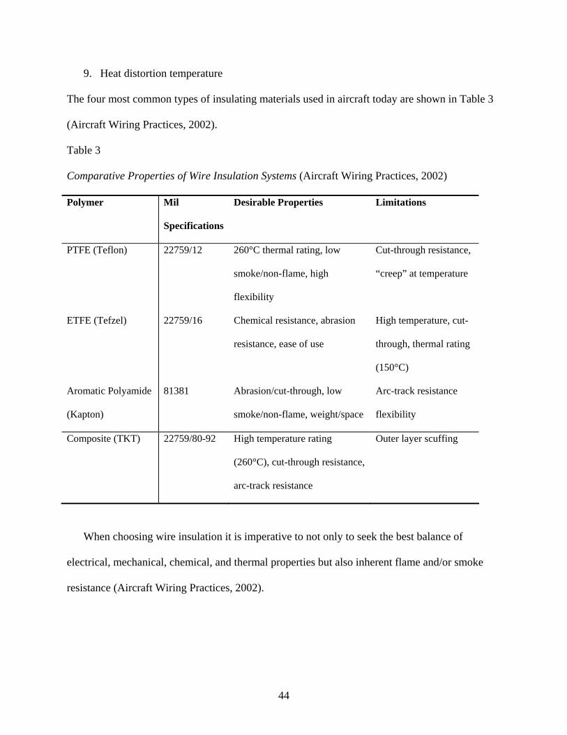
9. Heat distortion temperature
The four most common types of insulating materials used in aircraft today are shown in Table 3
(Aircraft Wiring Practices, 2002).
Table 3
Comparative Properties of Wire Insulation Systems (Aircraft Wiring Practices, 2002)
Polymer Mil
Specifications
Desirable Properties Limitations
PTFE (Teflon) 22759/12 260°C thermal rating, low
smoke/non-flame, high
flexibility
Cut-through resistance,
“creep” at temperature
ETFE (Tefzel) 22759/16 Chemical resistance, abrasion
resistance, ease of use
High temperature, cut-
through, thermal rating
(150°C)
Aromatic Polyamide
(Kapton)
81381 Abrasion/cut-through, low
smoke/non-flame, weight/space
Arc-track resistance
flexibility
Composite (TKT) 22759/80-92 High temperature rating
(260°C), cut-through resistance,
arc-track resistance
Outer layer scuffing
When choosing wire insulation it is imperative to not only to seek the best balance of
electrical, mechanical, chemical, and thermal properties but also inherent flame and/or smoke
resistance (Aircraft Wiring Practices, 2002).
44

Cleaning
All aircraft wiring needs to be kept clean throughout the life of the aircraft. This can be
accomplished by cleaning wiring periodically during heavy maintenance when hidden areas are
exposed. Care should be taken when wiring is being cleaned especially as the aircraft and its
wiring age. As aircraft age, the wire insulation becomes brittle, so moving of wiring during
cleaning should be minimized. Vacuuming and soft brushes may be used to remove dirt, lint, and
other foreign objects (Aircraft Wiring Practices, 2002).
45
CHAPTER 4
CURRENT WIRE MAINTENANCE METHODS UTILIZED
IN THE AVIATION INDUSTRY
Wiring integrity and safety issues have surfaced as a major aviation crisis associated with the
loss of Swissair flight 111 in 1998 and TWA flight 800 in 1996. Aircraft wiring is the vital
electrical and optical network that transmits the data, signals and power to and from systems.
Wiring problems cause loss of signals, system shutdowns, smoke, fires, and explosions. In
addition, wiring problems cause millions of dollars in troubleshooting and maintenance (Blemel
& Furse, 2001).
The National Transportation Safety Board (NTSB) and the U.S. Federal Aviation
Administration (FAA) have adequately “heightened (their) awareness of the importance of
maintaining the integrity of aircraft wiring (NTSB 303).” Ensuring flight safety entails more
immediate detection of electrical malfunctions and better fire suppression methods. However,
avoiding flight tragedies involves improving wire inspection techniques.
According to the National Transportation Safety Board, aircraft wiring is visually inspected,
but “a large portion of an aircraft’s electrical wiring is not readily visible” because it is “bundled
with dozens of other wires” or “blocked from view by other structures or components (NTSB
194).”
Visual inspection refers to “a non-intrusive check examining wiring for chafing and signs of
arc tracking using floodlights, flashlights and mirrors. Detailed visual inspection refers to
intrusive removal of clamps along with disconnecting harnesses to check for cracks and exposed
conductors with illumination and magnifying glasses (Blemel & Furse, 2001).”
46

Table 4 lists several common wiring problems, primary indicators, and current techniques used
to correct them (Blemel, & Furse, 2001).
Table 4
Wiring Problems, Indicators and Detection Methods (Blemel, & Furse, 2001)
Impending Failure Primary Indicator Detection Method
Badly chafed wiring Worn spots Visual inspection
Radar and thermal conductivity
Defective connections Major impedance change
Localized heating
Reflectometry, Thermal
Detectors, end-to-end tests
Ticking short circuits Electromagnetic Interference
Arc tracking
Visual inspection
Reflectometry
Solid short circuits Circuit breaker trips Reflectometry
Deteriorated insulation Cracks, broken areas Visual inspection
Exposed conductors Loss of functionality
Fires
Visual inspection
Reflectometry
Corrosion Eventual loss of signal/data Visual inspection
Water in harness Loss of data/signal Reflectometry
Today’s typical aircraft wiring inspections are visual and they do not get to the heart of
aircraft wiring problems. Failures such as severed wires are detected, but individual visual
inspections do not expose the slow but continuous erosion of wiring that results from thousands
of miles flown in the aircraft’s lifetime. In most cases, visual inspection entails pin to pin tests by
technicians with voltmeters and is considered to be slow, expensive, error prone, and not able to
detect many of the wiring anomalies (Tambouratzis, 2001).
47

A number of insulation cracks cannot be identified by visual inspection. These cracks are
usually smaller than a human hair but can nevertheless cause operational problems or loss of an
aircraft. Wire insulation may appear to be in perfect condition, but as it ages it becomes weak
and prone to danger. Wires in bundles wrapped in tape and covered with coaxial metal sheathing
are impossible to inspect visually. In reality, the twisting and pulling of aircraft wires to locate
wire failures is considered intrusive and recognized as often doing more harm than good.
Visual inspection detects “only 25 to 39 percent of the defects that (can be) identified” using
“electronic inspection techniques” performed by automated test equipment, such as “electrical
continuity or resistance tests, insulation resistance and capacitance tests (NTSB 194-5),” and
time domain, frequency domain, and standing wave reflectometry (Hast & Madaras 2001).
Handheld
Handheld tools are classified as battery operated, single or multifunction meters
approximately the size of a handheld multimeter. The readout format for multimeters can be
either analog or digital; however, digital displays are preferred. Both analog and digital
multimeters are used to find electronic and electrical problems (D’Angelo et al., 2001).
Analog multimeters are instruments that are used to measure electrical quantities for instance
voltage, current, resistance, frequency, and signal power. Advanced analog multimeters will
incorporate more features such as capacitor, diode and integrated chip testing modes. Analog
multimeters display measurement values using a dial, typically a moving pointer or needle
(GlobalSpec, 2004).
Digital multimeters are instruments that are used to measure electrical quantities for example
voltage, current, resistance, frequency, temperature, capacitance, and time period measurements.
Advanced digital multimeters contain additional features such as capacitor, diode, and integrated
48

chip testing modes. Digital multimeters display measurement values on a digital screen. In
general, the multimeters have between three and six digits but some units will have larger
screens that can display seven or more digits (GlobalSpec, 2004).
Figures 14 and 15 show examples of digital and analog multimeters (Tequipment.net, 2004).
Figure 14. BK 5380 Digital Multimeter Figure 15. BK114B Analog Multimeter
(Tequipment.net, 2004). (Tequipment.net, 2004).
Handheld multimeters are used in aircraft wire testing for identification of open or short
circuits, indication of fault, indication of wire insulation degradation, and isolation of
intermittent faults (D’Angelo et al., 2001).
In February 2000, the Air Force Research Laboratory (AFRL), Materials and Manufacturing
Directorate started a comprehensive program to look into the condition of the wiring systems of
representative fighter, bomber, and transport aircraft. An international team conducted and
49
documented site surveys of the three Air Force depots and several field level maintenance
operations. To accomplish the overall objective, site visits were made to identify types of wire
system faults that exist and to identify the types of tools and techniques needed to detect the
faults. Results from the research demonstrated that current visual inspection methods and
handheld tools only identify one fourth of all wiring problems discovered. In addition, the
research showed that a multimeter is the most often used piece of test equipment for
troubleshooting aircraft wiring. It takes two maintenance personnel a minimum of two to three
hours to verify continuity on a 100-120-wire harness using a multimeter. This piece of test
equipment is usually preferred since it is easy to use, portable and easy to interpret the results
(D’Angelo, Dicks, & Slenski, 2000).
The following is a list of some multimeter manufacturers and handheld multimeters typically
used to perform electronic tests and measurements in aircrafts.
Brighton Electronics
Brighton Electronics manufactures the following digital multimeters: Summit series with
model numbers 35, 45, 50, 60, 70, 85, 86, 610, 620, 622, and 786. Summit series digital
multimeter unique features are as follows (Brighton Electronics, 2002):
a. Compare mode and relative mode capability
b. Record mode including minimum, maximum, and average values
c. Triple readout display
Test Products International
Test Products International manufactures digital multimeters, which include: TPI models
120, 126, 133, 135, 153, 163, and 183(Test Products International, 2004).
50

B & K Precision
B & K Precision Corporation manufactures both analog and digital multimeters. BK models
114B and 117B make up the analog meters; the digital meters include BK models 2405A,
2407A, 2408, 2700, 2703B, 2704B, 2706A, 2707A, 2708, 2880A, 2890, 5360, 5370, 5380, and
5390. B & K multimeters are characterized by the following features (B & K Precision, 2004):
a. Range hold capability
b. Peak hold capability
Fluke Corporation
Fluke Corporation manufactures the following digital multimeters: Fluke series 10, 73/77,
80, 110, 112, 170, 179, 180, and 867B. Fluke multimeters exemplify the ability to record
minimum to maximum readings with time stamp (Fluke, 2004).
Kenwood TMI Corporation
Kenwood TMI Corporation manufactures the following digital multimeters: Kenwood series
DL-90, DL-92, DL-94, and DL-97. Kenwood multimeters are characterized by the following
features (Kenwood, 2001):
a. Maximum and minimum data memory
b. Data storage and recall capability
c. Peak hold capability
d. Square wave output function
e. Timer output function
f. Current input connection alarm that generates alarm buzzer sound when an attempt is
made to measure voltage while a test lead is still connected to the current input.
Table 5 shows a comparison between multimeter features and manufacturers
51
Table 5
Characteristics of Multimeters and Manufacturers
Man
ufac
ture
r D
ispl
ay C
ount
Bas
ic D
C V
olt
Acc
urac
y
Tru
e R
MS
mea
sure
men
ts
RS
232
Inte
rfac
e A
nalo
g B
ar
Gra
ph
Aut
o/M
anua
l R
angi
ng
Safe
ty
Stan
dard
s
Dat
a H
old
Bac
klig
ht
Dis
play
Pr
ice
Ran
ge
Brighton Electronics
2000-4000
0.3%- 0.5%
Yes Yes Yes Yes CE & IEC 1010 CAT II
Yes Yes $105.95-$215.95
TPI
2000-4000
0.3%-0.5%
No No Yes Yes CE/UL Yes No $32.95-$159.95
B & K 2000-50,000
0.25% Yes Yes Yes Yes CE Yes Yes $35-$325
Fluke 3200-50,000
0.025%-0.9%
Yes Yes Yes Yes IEC 1010 CAT III, IV
Yes Yes $109-$579
Kenwood 3200-5000
0.06%- 0.5%
Yes Yes Yes Yes EN55011 IEC 801-2,3,4
Yes Yes $115-$455
The handheld multimeter has the following limitations (D’Angelo et al., 2001):
1. It is a time consuming process especially when trying to isolate the wire system faults
pin-by-pin.
2. It requires two people to allow for connection at both ends.
3. There are no data archiving or retrieving capabilities.
4. It is an extensive process to physically locate wire failures.
The handheld multimeter does not adequately measure all aspects of aircraft wiring
anomalies, for that reason other test equipment that have enhanced capabilities over current
multimeters have been developed and implemented.
Time Domain Reflectometry
Time domain reflectometry is “the analysis of a conductor (wire, cable or fiber optic) by
sending a pulsed signal into the conductor and then examining the reflection of that pulse (Furse,
52

& Waddoups, 2001).” The incident and reflected signals are both seen on the wire
simultaneously, although their time domain signatures are separated in time because of the travel
time delay down the wire. By analyzing the reflected pulse, the length of the wire, impedance
and the location of open or short circuits can be determined. Large changes in the wire (open or
short circuits) cause large reflections that are easy to measure and small changes in the wire
(junctions or frays etc), cause smaller reflections that are hard to detect (Furse, 2003).
Time domain reflectometry electronics consist of a fast rise time pulse generator, fast voltage
sampler, and a microprocessor to analyze the results. The time domain reflectometer determines
the length of the wire based on the time it takes for the reflection to return to the source. The
polarity of the reflection can be used to further examine the wire fault. A reflected pulse that
increases in amplitude denotes an open circuit (high impedance). Conversely, a reflected pulse
that decreases in amplitude signifies a short circuit (low impedance) (Parker n.d.).
A time domain reflectometer can display the information it receives in two formats. The first
and more conventional method is to display the actual waveform of the wire. The display, which
is either a cathode ray tube or a liquid crystal display, will show the transmitted pulse generated
by the time domain reflectometer and any reflections that are caused by impedance changes
along the length of the wire. The second method is a numeric readout that specifies the distance
in feet or meters to the first major reflection caused by a fault along the wire. Some time domain
reflectometers will identify if the fault is an open or short circuit.
Figure 16 shows the different types of time domain reflectometers (Riserbond, 2004).
53

Figure 16. Types of Time Domain Reflectometers (Riserbond, 2004).
The following is a list of some time domain reflectometer manufacturers typically used to
perform electronic tests and measurements in aircrafts.
Riser Bond Instruments
Riser Bond Instruments is a division of Radiodetection Ltd that specializes in the design and
manufacturing of time domain reflectometers, which include models 1205CXA, 1270A, 1550,
3200, 3300, and 6000. Riser Bond Instruments’ time domain reflectometers are characterized by
the following features (Riser Bond, 2004):
Super-store waveform storage stores all of the waveform information shown both on and off the
screen.
a. Wave view software allows information stored in the time domain reflectometer to be
uploaded to a computer waveform and can be archived, adjusted, or analyzed on the
computer while the time domain reflectometer carries out other tests.
b. Auto search makes it possible for the operator to quickly and easily step through
preset distance range and pulse width settings to accomplish other manual operations.
c. Auto noise filter offers a unique multilevel filtering system to filter out various kinds
of interferences on the wire.
54

d. Independent cursors allow the operator to measure the distance between any two
points along the wire, thereby allowing the user to maintain the accuracy of the test.
e. Complies to ISO 9001 and CE safety standards
Phoenix Aviation and Technology
Phoenix Aviation and Technology has developed a fully automated time domain
reflectometer unit that offers a wider range of fault diagnostics and prognostics with exact
location and interpretation of the wire faults. This technology allows the operator to monitor a
single conductor wire condition, circuit status, and load analysis in real time (Furse & Haupt,
2001).
Bicotest
Bicotest designs and manufactures precision time domain reflectometers and cable test
instruments for cable fault location, test and measurement, installation, and maintenance on
power distribution cables, twisted pair cables, and coaxial cables. T 631 time domain
reflectometer is a high specification wire fault locator used for fault location on aircraft fire
detection systems. T 631 time domain reflectometer is characterized by the following features
(Bicotest, 2002):
a. Genuine two-nanosecond pulse width gives excellent close fault finding detection and
examination of the condition of the wire.
b. It gives the best short-range performance of three meters and long-range performance
of twelve kilometers.
c. Availability of 13 operating ranges with zoom facility make it possible to identify
wire features that are close together or nearby.
55
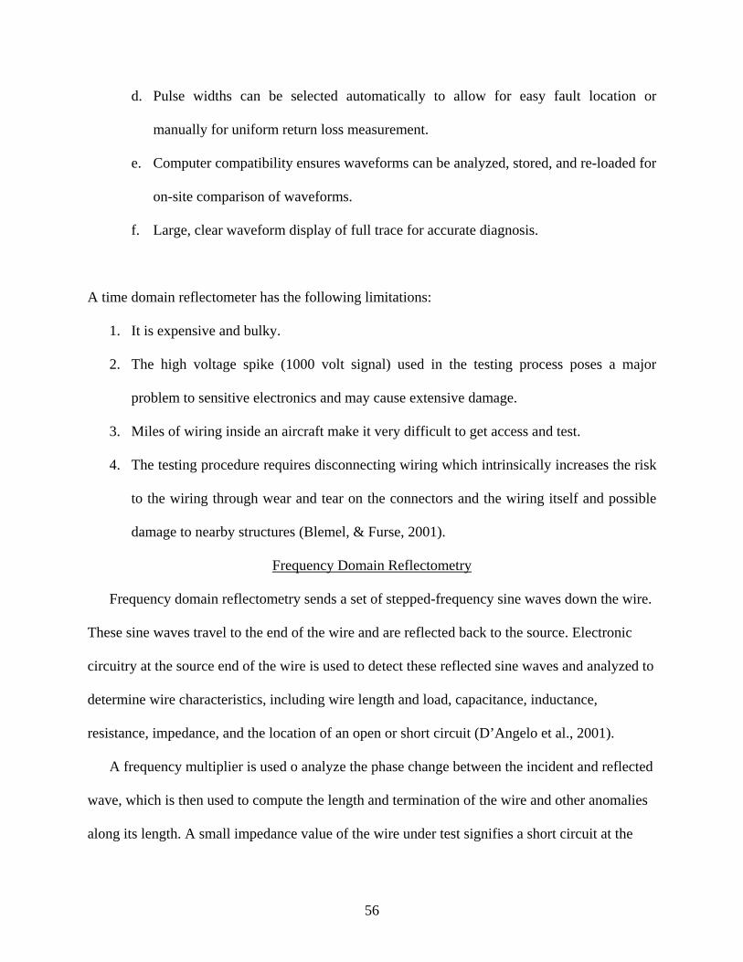
d. Pulse widths can be selected automatically to allow for easy fault location or
manually for uniform return loss measurement.
e. Computer compatibility ensures waveforms can be analyzed, stored, and re-loaded for
on-site comparison of waveforms.
f. Large, clear waveform display of full trace for accurate diagnosis.
A time domain reflectometer has the following limitations:
1. It is expensive and bulky.
2. The high voltage spike (1000 volt signal) used in the testing process poses a major
problem to sensitive electronics and may cause extensive damage.
3. Miles of wiring inside an aircraft make it very difficult to get access and test.
4. The testing procedure requires disconnecting wiring which intrinsically increases the risk
to the wiring through wear and tear on the connectors and the wiring itself and possible
damage to nearby structures (Blemel, & Furse, 2001).
Frequency Domain Reflectometry
Frequency domain reflectometry sends a set of stepped-frequency sine waves down the wire.
These sine waves travel to the end of the wire and are reflected back to the source. Electronic
circuitry at the source end of the wire is used to detect these reflected sine waves and analyzed to
determine wire characteristics, including wire length and load, capacitance, inductance,
resistance, impedance, and the location of an open or short circuit (D’Angelo et al., 2001).
A frequency multiplier is used o analyze the phase change between the incident and reflected
wave, which is then used to compute the length and termination of the wire and other anomalies
along its length. A small impedance value of the wire under test signifies a short circuit at the
56

point of termination. In contrast, a large impedance value of the wire denotes an open circuit at
the point of termination (Furse, 2003).
Frequency domain reflectometer circuitry is comprised of a stepped frequency sine wave
generator and either a frequency counter, a received signal strength indicator chip, or a frequency
multiplier and DC voltage measurement hardware. A frequency domain reflectometer is less
bulky than a time domain reflectometer for that reason; it can be used in more locations that are
otherwise more difficult to get access to with bulkier systems like a time domain reflectometer.
In addition, a frequency domain reflectometer system uses less power than a time domain
reflectometer system making it a safe method to use in detecting impedance changes in aircraft
wiring (Furse & Nilesh, 2004).
Frequency domain and time domain reflectometry are some of the current maintenance
methods used to detect wire failures in aircraft systems. Despite the fact that these techniques
permit identification and localization of hard wiring failures, they are unable to monitor
degradation associated with wire insulation and corrosion. Furthermore, these reflectometry
systems are only performed when the aircraft is out of service, and they are unable to predict
wire failures and identify sources of damage before wire failures arise in aircrafts.
Standing Wave Reflectometry
A standing wave reflectometer sends a high frequency sinusoidal waveform down the wire
and detects any interruption in the wire impedance, thereby determining wire characteristics such
as integrity, length, and impedance. Impedance is a measure of the total opposition to current
flow in a circuit. Any change in the impedance of the wire causes a reflection of the transmitted
signal to take place at the point where there is interference in impedance uniformity. By the
nature of the reflections that are generated on the wire, characteristics are noted using power and
57

voltage measurements to find out whether the impedance discontinuity is caused by a short or an
open circuit. The incident and reflected signals are merged together to produce a standing wave
on the line. The peaks and nulls of the standing wave provide information on the length of the
terminating load of the wire. (Furse & Waddoups, 2001). The amplitude of the standing wave
has maximum and minimum points on the wire that are dependent upon the frequency of the
incident wave (Furse & Woodward, 2003).
Eclypse International’s ESP standing wave reflectometer is a unique device that has been
analyzed for its ability to locate a short circuit or an open circuit on a wide range of wiring, such
as triaxial, multistranded, and even twisted pair. The ESP standing wave reflectometer is a
handheld, battery-operated test set with the capability of testing up to 1,000 feet from the test
unit and short or open circuit detection accuracy of 0.2 %, which equates to mere centimeters.
Once the test is carried out, the standing wave reflectometer reports the wiring system as okay,
degraded, or failed. If a fault exists, it identifies the location of the fault. Results from the
standing wave reflectometer can be downloaded to a laptop using its serial data port. The
graphical display on the standing wave reflectometer indicates the condition of the wire. A good
systems performance will be illustrated by a perfect sine wave, a degraded system will display an
averaged sum of distorted sine waves where the peaks appear dipped and a failed system will
show nothing but unrecognizable sine waves. The unit cost for a standing wave reflectometer is
$5,500 (Maher, 2004).
The ESP standing wave reflectometer is characterized by the following features (Maher,
2004):
1. Liquid crystal display that offers systems status, menu items, wire type, and the “ready
for test” display.
58

2. Ability to locate wiring faults in aircrafts in inaccessible areas.
3. Performs a non-destructive multiple frequency test protocol per wire path.
4. Menu driven test procedure and has ten programmable settings for various conductor
types.
5. Resultant test data on the computer screen can be saved as text files for future reference
against other installation.
6. Operating range of -20 to +60 degrees Celsius.
7. Rechargeable battery with an 8 hour operating life.
Figure17 is an example of a standing wave reflectometer (Pappas, 2001).
Figure 17. Standing Wave Reflectometer (Pappas, 2001).
A standing wave reflectometer is simple in its design making it less expensive to
manufacture than a typical time domain reflectometer. In addition, the standing wave
reflectometer promotes efficient utility with its portable nature, selectable frequency range, and
automatic operation (Nieto, 2000).
Implementation of the standing wave reflectometer in the Navy has resulted in fewer in-flight
electrical fires, reduced wiring related false equipment removals, fewer maintenance hours, and
rapid identification of wiring anomalies. Similarly, the applications of the standing wave
59
reflectometer in the commercial sector offers reduced man-hours, faster diagnostic test phases,
and faster aircraft turn around time from the ground (Commercial Technology Transition
Officer, 2003). The overall benefits of the standing wave reflectometer are reduced time and
effort to troubleshoot, repair and validate repairs, enable proactive maintenance, and most of all
lower total operating costs (Nieto, 2000).
Current visual inspection methods, handheld multimeters, time domain reflectometers, and
frequency domain reflectometers are the primary means to detect degradation in installed aircraft
wiring. Standing wave reflectometry is recognized as a means of localizing and identifying hard
faults. Nonetheless, it is not currently able to locate defects in wiring insulation, but the
technology could be adapted to do so. Due to the inherent limitations of the above techniques,
researchers are now looking at several inspection and maintenance protocols that include smart
wire systems and arc-fault circuit breakers. The aviation industry has embarked on several new
initiatives to develop advanced wiring technologies that will play an important role in enhancing
aircraft safety and operational availability.
60

CHAPTER 5
TRANSITION WIRE MAINTENANCE PROGRAMS
As an aircraft wiring system ages, the wiring system becomes more susceptible to anomalies
and failures, which can result in safety problems. The current maintenance approach of flying an
aircraft until a system failure is encountered is becoming more difficult to continue. New
maintenance methods will need to be incorporated to effectively manage aging wiring systems in
aircrafts.
There are several wire maintenance systems available today or under development for
detecting aircraft wiring problems. Among the most promising technologies are smart wire
systems for continual on- the- spot testing and arc fault circuit breakers. Honeywell’s Nova wire
integrity program was also developed to be a data-intensive wire inspection diagnostic tool.
Smart Wiring
Smart wiring is the “embedding of intelligence and sensors in the wiring system to manage
the health of the wiring (Arnason, Field, & Furse, 2001).” The components of the smart wiring
system include a frequency domain reflectometer, on-board processor, environmental sensors,
and wireless communication system integrated into a single miniaturized unit, hundreds of which
can be embedded in the wiring system.
Smart connectors and smart wiring signify a new approach to troubleshooting not only the
aircraft wiring but also the systems that are connected to the wiring. Smart wiring technology can
operate in real time during flight and can locate intermittent problems that occur during take-off,
cruise, and landing.
Management Sciences, Inc. (MSI) has been developing the hardware and software
technology for smart wiring systems and smart connectors since the start of a Joint Strike Fighter
61
(JSF) contract. The Joint Strike Fighter contract launched a research program in 1997 to explore
design of a new format of smart wiring, using time embedded processors and signal processing
for detecting opens and shorts in aircraft wiring (Blemel A. & Blemel G., 2000).
The U.S. Naval Air Systems Command estimates that $75 million is spent annually on wiring
related troubleshooting and maintenance, emphasizing the fact that finding shorts and opens in
aircraft wiring is costly. Smart connectors and smart wiring products significantly diminish the
costs of aircraft maintenance. At a rate of 20% application, the projected savings in labor would
surpass $15 million per year. The savings that result from preventing the loss of an aircraft due to
loss of systems, explosions, or fires may well exceed $50 million per occurrence (Blemel, 2000).
Smart wiring system is comprised of a microelectronics module with integral software signal
processing and sensors for the purpose of wiring signal and integrity. For smart wiring, the
module is enclosed inside a wiring integration unit or junction box added to conventional wiring.
For smart connectors, the module is connected to specifically modified connectors inside a
bulkhead-mounted unit. Sensing signals are issued to examine the aircraft wiring and digitizers
are utilized to monitor signals. Digital signal processing is used to find short, open and frayed
conditions in the aircraft wiring (Blemel, 2000).
Smart wiring technology combines hardware sensing and software algorithms and is
comprised of the following subcomponents:
1. Smart wiring harness – a variant of a smart connector that is assembled by placing the
electronics module into the wiring integration unit or junction box. A smart wiring
harness uses ordinary connectors in its design.
2. Smart connector – a bulkhead mounted unit provides a single processor with outreach
capabilities to inspect several wiring harnesses equipped with smart connector.
62
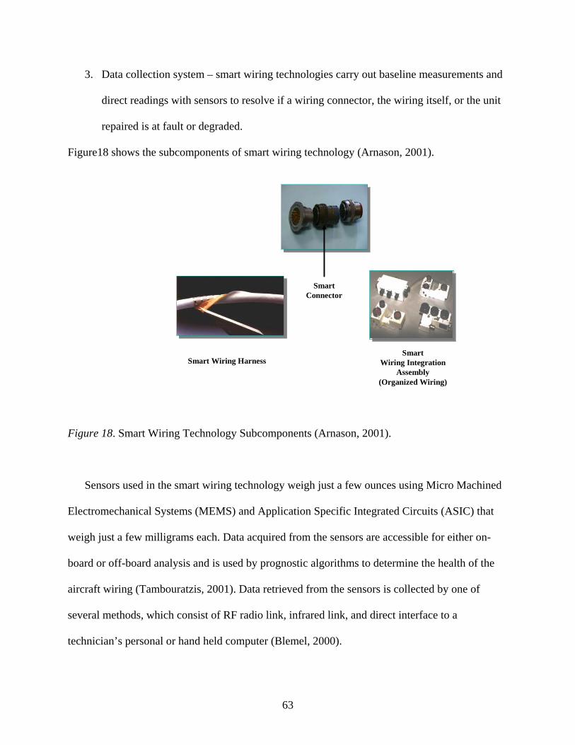
3. Data collection system – smart wiring technologies carry out baseline measurements and
direct readings with sensors to resolve if a wiring connector, the wiring itself, or the unit
repaired is at fault or degraded.
Figure18 shows the subcomponents of smart wiring technology (Arnason, 2001).
Smart Wiring Harness
SmartConnector
SmartWiring Integration
Assembly (Organized Wiring)
Figure 18. Smart Wiring Technology Subcomponents (Arnason, 2001).
Sensors used in the smart wiring technology weigh just a few ounces using Micro Machined
Electromechanical Systems (MEMS) and Application Specific Integrated Circuits (ASIC) that
weigh just a few milligrams each. Data acquired from the sensors are accessible for either on-
board or off-board analysis and is used by prognostic algorithms to determine the health of the
aircraft wiring (Tambouratzis, 2001). Data retrieved from the sensors is collected by one of
several methods, which consist of RF radio link, infrared link, and direct interface to a
technician’s personal or hand held computer (Blemel, 2000).
63

Smart wiring system can accurately identify the point of damage consequently, saving hours
of troubleshooting time across aircraft bulkheads. Technicians will be directed to exact locations
of wiring short, open, and frayed conditions rather than using current labor-intensive techniques.
In addition, the smart systems can monitor the components attached to the wiring and examine
whether a component is failed or is working. The smart wiring system is able to observe
performance of the component after reinsertion to guarantee its return to original condition
(Tambouratzis, 2001).
In May 2000, the office of Naval Research funded a two-year project for further research and
development of smart wiring leading to flight demonstrations in late 2001 (Blemel, 2000). The
Navy estimates savings that will result from the full implementation of the smart wiring
technology into Navy aircraft will be significant including the following:
1. 200,000 to 400,000 fewer organizational man-hours per year.
2. $34.5 million annual savings from reduced mission aborts and fewer mission capable
hours.
3. 80% reduction of in-flight electrical fires and subsequent loss of aircraft resulting in
$27.3 million annual savings.
Smart wiring systems are able to detect the causes of problems before they happen, thereby
making them very effective in preventing the occurrence of the problem through early warnings
to the crew and the maintenance personnel. The smart systems can have significant impacts for
enhancing aircraft safety, minimize false maintenance, and facilitate proactive maintenance that
will save costs, time, and human lives. A summary of the benefits of the smart wiring system is
highlighted in Table 6 (Blemel, 2000).
64

Table 6
Features, Advantages and Benefits of Smart Wiring (Blemel, 2000)
Features Advantages Benefits
Measures signals Reduce need for additional
hardware, particularly important
in aircraft where flight
certification is required
Lower integration costs
Detects and locates shorts, frays
and opens
Saves hours of time and use of
equipment for troubleshooting
Eliminates a cartload of test
equipment
Integrate into existing systems
with minimal change
No additional hardware required Lower integration costs
No ancillary processing All processing done in algorithm;
no secondary operations
Reduced complexity
Smart wiring systems apply to new and legacy aircraft wiring systems. For legacy aircraft,
modules can be added during a scheduled wiring system upgrade; a complete wiring system
replacement is not necessary. According to Naval Air Systems Command, initial insertion of the
smart wiring systems is scheduled for 2006 in P3 aircraft (Blemel & Furse, 2001).
Arc Fault Circuit Breakers
The primary device for protecting an aircraft from the hazards of electrical failures is the
circuit breaker. Circuit breakers currently used in most civilian and military aircraft are
comparable to those found in most household circuit breaker fuse boxes. Circuit breakers in use
today are heat sensitive bimetal elements that trip only when a large current passes through the
circuit long enough to heat the element (Furse & Haupt, 2001). They generally do not protect
65
against small sparks that can result from aging or frayed wires, causing either arcing between
individual wires or between the wire harness and the aircraft structure.
Circuit breakers are designed to protect the wiring from overheating related to wiring
overload or short circuits and not arcing. An arcing fault draws less current than a hard fault and
occurs intermittently while generating high temperatures that can ignite nearby combustibles. In
most cases, arcing faults occur in damaged or deteriorated wires and cords, which is a common
occurrence in aging aircraft (Phillips, 2004). Microscopic cracks, abrasions, or broken insulation
in aged wire will likewise instigate arcing faults.
Electrical arcing generates very hot localized temperatures nonetheless, the arcing might not
radiate enough energy for the circuit breaker or fuses to heat up sufficiently so that they trip or
remove power from the circuit rapidly enough to avoid serious damage to the electrical wiring.
Existing circuit breakers take up to several hundred milliseconds to diagnose a fault and then
trip. During that time, the adjacent wires heating up can result in failed systems, structural burns
and possible loss of aircraft (Phillips, 2004). To avoid the potential catastrophe that electrical
arcing could create, the Federal Aviation Administration (FAA) in cooperation with the Naval
Air Systems Command (NAVAIR) and the Office of Naval Research have developed aircraft arc
detecting circuit breakers.
Arc fault circuit breakers use integrated electronics to detect when arcs or intermittent short-
circuiting occurs in the wiring, then instantly isolates the circuit from the rest of the system
greatly reducing the threat of an electrical arc fire. Arc fault circuit breakers take about five
seconds to detect a fault and trip, thereby reducing the chance of damaging the surrounding
wiring, other equipment, and the aircraft structure (Phillips, 2004).
66
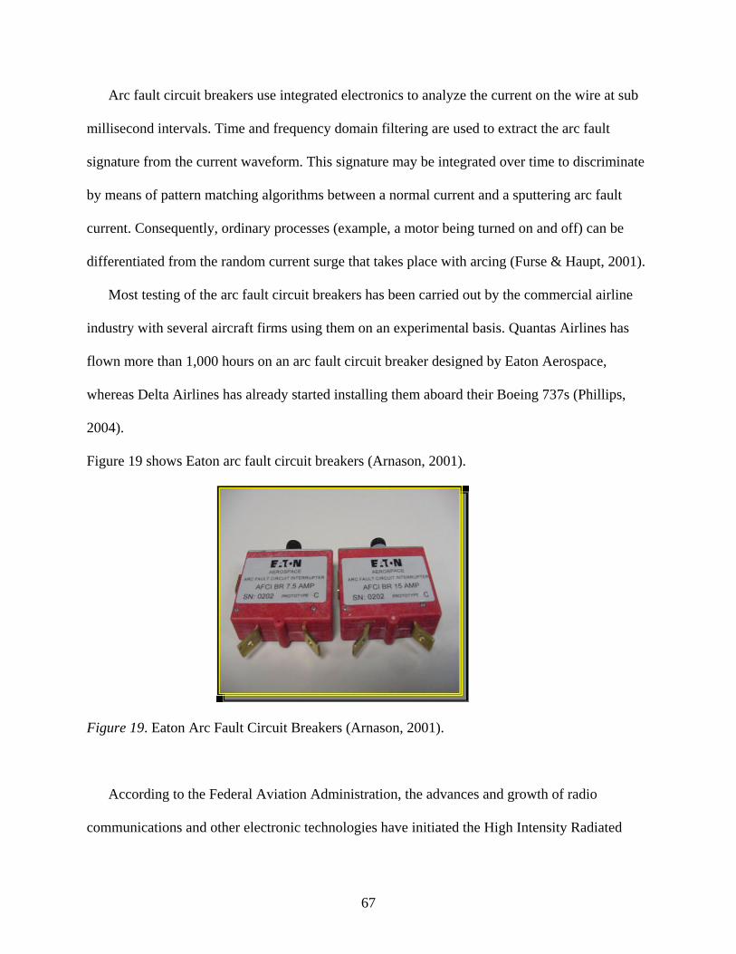
Arc fault circuit breakers use integrated electronics to analyze the current on the wire at sub
millisecond intervals. Time and frequency domain filtering are used to extract the arc fault
signature from the current waveform. This signature may be integrated over time to discriminate
by means of pattern matching algorithms between a normal current and a sputtering arc fault
current. Consequently, ordinary processes (example, a motor being turned on and off) can be
differentiated from the random current surge that takes place with arcing (Furse & Haupt, 2001).
Most testing of the arc fault circuit breakers has been carried out by the commercial airline
industry with several aircraft firms using them on an experimental basis. Quantas Airlines has
flown more than 1,000 hours on an arc fault circuit breaker designed by Eaton Aerospace,
whereas Delta Airlines has already started installing them aboard their Boeing 737s (Phillips,
2004).
Figure 19 shows Eaton arc fault circuit breakers (Arnason, 2001).
Figure 19. Eaton Arc Fault Circuit Breakers (Arnason, 2001).
According to the Federal Aviation Administration, the advances and growth of radio
communications and other electronic technologies have initiated the High Intensity Radiated
67
Field (HIRF) phenomena. At the present time, there are more than 500,000 emitters in the United
States and Western Europe contributing to the electromagnetic environment. Aircraft are
exposed to the HIRF environments that radiate from high-powered radio and television
frequency transmitters, radar and satellite uplink transmitters, and large microwave
communication systems (Phillips, 2004).
Research indicates that aircraft electrical and electronic systems that carry out critical
functions such as aircraft flight and navigation may not be able to withstand the electromagnetic
fields generated by HIRF. The vulnerability of aircraft electrical and electronic systems to
malfunction when exposed to HIRF can pose a threat to aviation safety systems (Phillips, 2004).
The High Intensity Radiated Field (HIRF) testing performed at the Navy Electromagnetic
Radiation Facility involved exposing the aircraft, a C-9 Skytrain, in high to low frequency
emitters. Emitters were located at varied angles to test not only the arc fault circuit breaker, but
also the cables leading to the breakers. The arc fault circuit breaker took one more step toward
fleet deployment by passing the Joint Aeronautics Association’s High Intensity Radiated Field
testing in January 2004. Although the HIRF testing is complete, the arc fault circuit breaker must
still go through lightning test and there are plans to test various sizes of the circuit breaker for
possible use in attack aircraft (Phillips, 2004)
According to the NAVAIR Aging Aircraft Integrated Process Team (IPT), arc fault circuit
breakers could cut down wiring maintenance costs by 80 % and provide an annual savings of $12
million. Benefits of the arc fault circuit breakers will not only be in terms of troubleshooting,
repair time reduction, and cost reduction but also in flight safety.
68

Nova
Honeywell has long recognized the importance of safety, reliability, diagnostics, physics of
failure, and prognostics in an aircraft. Honeywell has led a team of industry experts and has
developed the Nova Wire Integrity Program. According to Francois Gau, Director of Marketing
at Honeywell Aerospace Services, “the reliability and safety of wiring in older aircraft is a major
concern of operators throughout the industry (Shavarini p.3, 2002).” Honeywell has taken a
pioneering role in dealing with these issues and developed Nova.
Nova wire integrity program is “an integrated and portable system designed and developed
by Honeywell to test and identify faulty wiring and connections in older aircraft (Shavarini,
2002).” Nova system is based on advanced modeling, diagnostics software, and maintenance
planning from Qualtech Systems, which is collaborating with Honeywell in this endeavor. The
Remote Diagnostics Server (RDS) from Qualtech, which was mainly developed for NASA, is a
fundamental element in the Nova system.
Nova performs wiring system modeling, failure analysis, trend monitoring, prognostics,
diagnostic analysis, and data logging of test results and automatic test generation. The software
makes it possible for technicians to optimize their wiring test and maintenance strategy within
their current maintenance processes.
According to Kevin Cavanaugh, Qualtech’s chief operating officer, “users can upload test
data to the remote diagnostics server over the internet or other network. The data is then
automatically processed through the intelligent model-based reasoning in seconds, dynamically
generating an HTML web page display of the resulting diagnostics (Shavarini p.4, 2002).”The
remote diagnostics server makes it possible for intelligent dynamic tests, diagnostics and
maintenance procedures to be launched, thereby verifying the operational integrity of the wiring
69

system. In addition, the software is web based which allows for integration with the supply chain
system, logistics databases, and computerized maintenance management systems.
Nova wire integrity program employs intelligent telemaintenance to electronically test and
identify faulty wiring and connections in aircraft. The telemaintenance system not only analyzes
data streams and embedded sensors in networked subsystems but also troubleshoots and
identifies failures automatically in real time. Additionally, it provides ongoing health checks and
locates areas that might turn out to be problematic before they happen (Shavarini, 2002).
Use of real time fault detection and isolation solutions are fundamental to faster, less
expensive, and more effective operation of complex systems. Nova system reduces the likelihood
of operational failures and disasters resulting from a sudden failure, thereby improving system
safety and availability (Shavarini, 2002).
Gau states, “Qualtech’s software along with other powerful features within Nova empowers
operators to diagnose and locate most faults within the wiring system. Fully integrated Nova can
test 5, 000 wires in a minute and detect faults (shorts, open, insulation wear) and their location in
the aircraft to within 1 centimeter (0.39 inches) (Shavarini p.5, 2002).” Maintenance personnel
have several unit options to choose from, including how the unit is connected to the aircraft. The
smallest unit weighs 70 pounds and costs approximately $100,000 and the larger units can weigh
thousands of pounds and cost up to $1 million. According to Gau, irrespective of the size of the
system, each unit is designed to define faults within centimeters in Honeywell’s laboratory or
one to two feet within a hangar environment.
Some of the benefits of Nova system are in the following areas:
1. Manufacturing, where it can help ensure quality standards with building and installation
of wire bundles in aircrafts.
70
2. Flight line maintenance to quickly resolve specific wires with faults and validate their
location and criticality.
3. Heavy maintenance where tests can be performed during scheduled maintenance to
monitor the wire integrity of the aircraft.
4. Improved operational safety- wire failures and their criticality are quickly and
automatically identified and possibly alleviated.
5. Improved availability – because most of the system diagnosis is done online, and in real
time, downtime for troubleshooting and life cycle costs is minimized.
6. Improved confidence in system serviceability – the self testing and monitoring
capabilities of the remote diagnostics server continuously and accurately monitor the
health of the system with a high degree of certainty.
7. Automated testing and data archiving.
8. Reductions in staff required for testing aircraft wiring system.
Honeywell claims, “ about 3-10% of all maintenance hours are spent on wiring and estimates
that manual troubleshooting of an average narrow body aircraft could be reduced by 88% (from
$87,040 to $10,880) over a period of four years (Rosenberg, 2001). The end result is effective
preventive maintenance; locating wiring faults and preventing accidents, while cutting down on
operational costs.
Figure 20 illustrates troubleshooting time costs for an average narrow body aircraft over four
years (Overview of Nova, 2002).
71
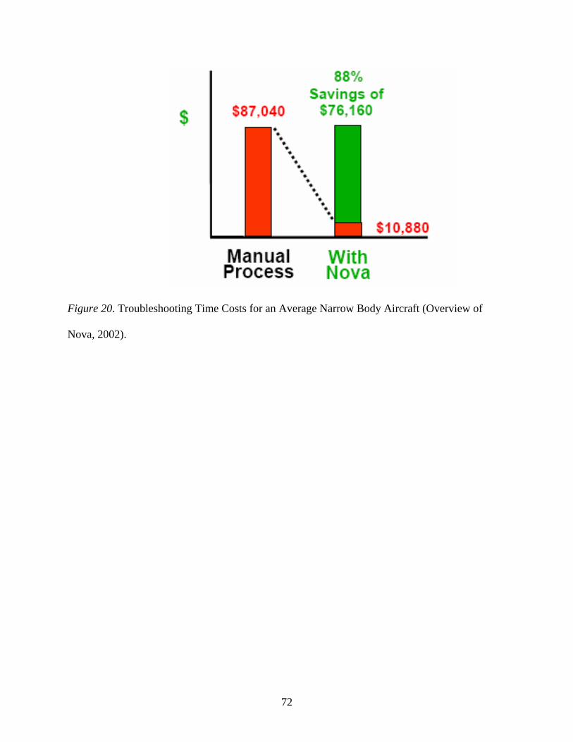
Figure 20. Troubleshooting Time Costs for an Average Narrow Body Aircraft (Overview of
Nova, 2002).
72

Table 7 outlines Advanced Nova Test Capabilities (Overview of Nova, 2002).
Table 7
Advanced Nova Test Capabilities (Overview of Nova, 2002)
Significant improvement in wiring integrity can only be accomplished by moving from a
reactive to a proactive wiring system maintenance approach. Development and implementation
of new wiring inspection technologies will result in substantial maintenance cost savings,
reduction in in-flight electrical fires, and enhance passenger and crew safety.
73
CHAPTER 6
ANALYSIS OF THE CONVENTIONAL AND TRANSITION
WIRE MAINTENANCE METHODS
In July 1998, the Federal Aviation Administration (FAA) announced their Aging Transport
Non-Structural Plan. The details of the plan are highlighted in the following statement
concerning current wiring maintenance practice:
“Current maintenance practices do not adequately address wiring components (wire, wire
bundles, connectors, clamps, grounds, shielding). Inspection criteria is too general. Typically a
zonal inspection task card would say to perform a general visual inspection. Important details
pertaining to unacceptable conditions are lacking. Under current maintenance inspection
practices, wire is inspected visually. Inspection of individual wire in bundles and connectors is
not practical because aged wire is stiff and dismantling of bundles and connectors may introduce
safety hazards. Wiring inside conduits is not inspectable by visual means. The current
presentation and arrangement of standard practices make it difficult for an aircraft maintenance
technician to locate and extract the pertinent and applicable data necessary to effect satisfactory
repairs. Under current maintenance philosophy, wire in conduits is not inspected. A review of
incident reports and maintenance records indicate current reporting system lacks visibility for
wiring making it difficult to assess aging trends (FAA Aging Transport Non-Structural Systems
Plan, p.5 1998).
The above paragraph clearly shows that visual inspection, which is the current maintenance
practice for both commercial and military aircraft, has intrinsic disadvantages and is not the most
effective method of wiring maintenance. Current inspection and troubleshooting are often limited
to visual identification and verification with a multimeter.
74

The conventional wire maintenance methods used in the aviation industry include the
handheld multimeter, time domain, frequency domain, and standing wave reflectometer.
Handheld Multimeter
By far the most commonly used piece of equipment in aircraft wiring maintenance is the
handheld multimeter. A handheld multimeter is typically used in aircraft wire testing to locate
wire open or short circuits. A handheld multimeter is limited in its abilities to measure certain
aspects of wiring anomalies. For example, a multi-strand wire could be hanging by a few strands
and pass electrically with the multimeter on the ground. That same wire may be cause for failure
when the aircraft is in the air under load conditions (D’Angelo et al., 2000).
Time Domain Reflectometer
A fully automated time domain reflectometer offers a wide range of fault diagnostics and
prognostics with exact location and interpretation of wire faults in aircrafts. Computer
compatibility allows information stored in the time domain reflectometer to be uploaded to a
computer waveform. This ensures waveforms can be adjusted or analyzed on the computer while
the time domain reflectometer carries out other tests. This storage features allows for data
retrieval and archiving. Impedance changes along the length of the aircraft wire will identify if
the wire fault is an open or short circuit.
Frequency Domain Reflectometer
A frequency domain reflectometer analyzes the reflected sine waves to determine if the
impedance changes are as a result of an open or short circuit. A frequency domain reflectometer
is an efficient and safe method for detecting impedance changes in aircraft wiring because it
consumes less power than a time domain reflectometer.
75

Standing Wave Reflectometer
A standing wave reflectometer is best described as an impedance based cable tester. The
standing wave reflectometer is considered to be non-intrusive and highly accurate in fault
detection. This is because it can provide the distance to discontinuity in an electrical cable
without removal of the cable from the circuitry to which it is connected.
Many of the conventional maintenance approaches are reactive and only address wiring when
a failure cannot be resolved. Added onto this, these conventional maintenance practices lack the
effectiveness to manage and maintain the aircraft wiring anomalies prior to flight. More
proactive methods are needed so that aircraft wiring failures can be anticipated and wiring
systems can be replaced during scheduled maintenance activities.
Smart Wiring
Smart wiring technology provides diagnostic and prognostic capabilities as well as
documentation of the current condition of an aircraft wiring system on a Bureau Number (BuNo)
basis. This health tracking system is intended to be proactive in repairing wire failures by
addressing them during planned maintenance (Nieto, 2000). Smart wiring and smart connectors
have the sensors and embedded processing that facilitates early inspection and detection of short
and open conditions in the aircraft wiring without the dangers caused by high voltages used in
other testing methods (Blemel & Furse, 2001).
Smart wiring system components are positioned in-situ; this enables them to detect not only
the occurrence of the problem but also the causes of the problems, consequently creating a
proactive environment that senses leading indicators of the problems (Blemel & Furse, 2001).
Implementing a smart wiring system into existing platforms basically implies rewiring the
aircraft which would be highly intrusive, labor intensive, time consuming, and very costly
76

(Nieto, 2000). Despite this, given the benefits that would result from installing a smart wire
system, the high costs involved would pay off in the long run.
Arc Fault Circuit Breakers
The Federal Aviation Administration (FAA) approximates that “the deterioration of electrical
wiring in aging aircraft including cracked insulation, the contamination of wire bundles, normal
maintenance wear and damage and thermal cycling-all contribute to the potential for a 6,000
degrees Fahrenheit arcing event that cannot be detected by standard aviation circuit breakers
(Parsons, 2003)”. These undetected incidences could eventually lead to a disastrous electrical
fire. Electrical arcing is a major cause of in-flight electrical fire in the aviation industry. The
Federal Aviation Administration (FAA), National Transportation Safety Board (NTSB), and the
Transportation Safety Board of Canada investigations believe that electrical systems arcing
contributed to the crash of TWA Flight 800 in 1996 and Swiss Air Flight 111 in 1998.
An arc fault circuit breaker is designed to react faster to the presence of arcing and shutdown
the electrical load before a fire can result, thereby minimizing the number of electrical fires in
aircraft. A comparison between arc fault circuit breakers and smart wire systems show that arc
fault circuit breakers are less intrusive to install and address a key safety concern of arcing in
power distribution systems. Arc fault circuit breakers effectively manage aircraft wiring systems
by detecting and preventing electrical arcing before it damages the surrounding wiring, other
equipment and the aircraft structure. In addition, it significantly cuts down aircraft inspection and
maintenance costs.
Nova
Nova wire integrity program is “an efficient, proactive and comprehensive aircraft wire
maintenance system (Overview of Nova, 2002)”. Nova program is specialized for each user.
77
Honeywell examines each user’s troubleshooting data and verifies which systems failed most
frequently. This is then followed by Honeywell’s six sigma approach which is as follows
(Overview of Nova, 2002).
1. Define the scope of the problem- aircraft type and location (1-2 days).
2. Measure the amplitude of the problem- data mining maintenance records and refine
criteria based on operational profile (1-2 weeks).
3. Analyze the data- most frequent systems and critical systems isolated (1-2 weeks).
4. Implement the solution- model the systems in Nova’s software, design and order
adapters, select customize, and order Nova’s hardware and software package and finally
train users (3-6 weeks).
5. Control and monitor results by the aircraft (ongoing process).
Because Honeywell loads all of the probability and systems data into the unit, a technician
can look at the probability of failure while inspecting the aircraft wiring system. This proactive
approach can help operators and maintenance shops schedule maintenance ahead of time, instead
of waiting for a problem to arise and cause schedule interruptions (Overview of Nova, 2002).
Conventional wire maintenance methods generally require disconnecting both ends of the wire to
perform tests conversely; Nova system does not require wire disconnection and it locates open
and short circuits with a high degree of accuracy from one end of the wire.
Smart wire systems and arc fault circuit breakers usually perform one or two tests on the
aircraft wiring system. On the contrary, Nova system performs twenty different tests
simultaneously on a single wire. In addition, Nova quickly carries out multiple tests across
multiple bundles and multiple wires, thereby allowing it to continuously and accurately monitor
the electrical system of the aircraft. Nova system inspects aircraft wiring on an ongoing basis,
78

hence wiring anomalies can be automatically identified and possibly alleviated before they affect
the overall wire integrity system and cause accidents. Nova system signifies a remarkable and
innovative solution to diagnosing aircraft wiring problems and proactively managing the health
of aircraft wiring systems. Unfortunately, according to Jeff Rollins of Honeywell, “industry
conditions have made it clear that the timing of Nova was not matched to the current
environment.” As a result of this, the Nova program has been shelved until market conditions
are favorable.
Table 8 shows a summary of the analysis between conventional and transition wire maintenance
programs.
Table 8
Analysis Between Conventional and Transition Wire Maintenance Methods
Maintenance Method
Wire Fault Detection Capabilities
Data Retrieval & Archiving
Wire Disconnect
At both ends
Early detection & Identification
of Wire Failures
Handheld Multimeter
Detects electrical shorts & opens
No Yes No
Time Domain Reflectometer
Detects electrical shorts & opens
Yes Yes No
Frequency Domain Reflectometer
Detects electrical shorts & opens
No Yes No
Standing Wave Reflectometer
Detects electrical shorts & opens
Yes Yes No
Smart Wiring Detects electrical shorts, opens, frayed condition & intermittent connections
Yes No Yes
Arc Fault Circuit Breakers
Detects electrical arcing & intermittent short circuiting
No No Yes
Nova Detects electrical shorts, opens, damaged insulation, conductor, shields & connectors
Yes No Yes
79
Conventional wire maintenance practices require disconnecting the aircraft wiring at both
ends to perform electrical test which inherently increases the risk to the aircraft wiring through
wear and tear on the connectors, and the wiring itself and possible damage to the nearby
structures. These programs are also reactive in nature and only address wiring when the failure
has already happened. In contrast, transition maintenance programs do not require disconnection
at both ends of the wire to perform the electrical tests. In addition, they facilitate inspection and
early detection of wire failures before they affect electrical system operation. These transition
programs depict a proactive wire maintenance approach designed to improve the overall wire
system integrity and minimize maintenance costs, time and enhance flight safety.
80

CHAPTER 7
CONCLUSIONS AND RECOMMENDATIONS
Aging wiring presents a dangerous and complex problem for the commercial and military
aviation. Recent air disasters in both the commercial and military aviation clearly point out that
the effects of aging on aircraft wiring can be catastrophic. As aircraft continue to be used beyond
their intended life, more problems due to aging become more evident.
Aging aircraft wiring poses a problem for aircraft maintenance. This is due to the tremendous
amount of time spent on troubleshooting wiring to fix repairs and high maintenance costs. In
addition, current maintenance practices do not effectively manage the aging wiring problem.
Aviation technicians need to be provided with the correct maintenance tools and practices to
combat the aging wiring dilemma. This thesis provides the conclusions and recommendations for
addressing the aging wiring problem.
Conclusions
Aircraft Wiring Ages and Deteriorates Over Time
All aircraft electrical wiring systems are liable to aging during their normal service life.
Aging results in the progressive deterioration of physical properties and performance of wiring
systems with the passage of time. Wiring is susceptible to more rapid deterioration with age in
areas of high contamination, vibration, temperature variation, and corrosion and where it is
attached to movable or removable parts. The aging process can be significantly accelerated by
frequent handling or maintenance actions on or near the wiring systems. As aircraft continue to
fly for long periods of time, the occurrence of wire degradation gets higher consequently,
increasing the number of wire failures.
81
Aging Wiring Severely Impacts Aircraft Safety
The Federal Aviation Administration (FAA) and the National Transportation Safety Board
(NTSB) have reported hundreds of potential hazardous incidents of smoke and electrical
problems in aircraft cabins and cockpits. Table 1 lists a few examples of incidents involving
electrical problems. Aircraft accident investigators have attributed Swiss Air Flight 111 in 1998
and TWA Flight 800 in 1996 to fires caused by aged and damaged electrical wiring. In 2000, a
recent review of system discrepancy reports showed that commercial aircraft were experiencing
an average of three smoke and fire events per day. The data pointed out that approximately a
thousand of these events happening per year are directly linked to electrical anomalies. A Navy
study of NAVAIR found in-flight electrical fires related to wiring occurring at a rate of
approximately two per month. This study found that the Navy was spending about 1.8 million
man-hours per year troubleshooting and repairing wiring systems. These studies have made clear
that aging wiring is a serious problem that can lead to loss of critical aircraft systems, onboard
fires, and ultimately loss of an aircraft.
Current Maintenance Programs do Not Effectively Address Aircraft Wiring
As stated by the FAA’s Aging Non-Structural Plan dated July 1998, many of the current
maintenance practices are reactive and only address the wiring system failure after it occurs.
Table 4 shows how frequent visual inspection is used as the primary method to detect wire
failures. Visual inspection is primarily used today to inspect the condition of both commercial
and military aircraft wiring and to control aging mechanisms and damage resulting from normal
operation and maintenance.
NTSB 194-5 states that visual inspection only detects 29-39% of wire defects and is
considered to be time consuming. Visual inspection limits the degree to which aircraft wiring can
82

be inspected effectively without increasing the risk of damaging the wiring during inspection.
This is because most wires are difficult or impossible to see due to their location within the
aircraft or position within a large bundle of wires. For that reason, more proactive maintenance
methods are needed so that aircraft wiring failures can be inspected and detected before they
affect the electrical system operation.
Recommendations
Incorporate Proactive Wire Maintenance Programs
Smart wire systems, arc fault circuit breakers, and Nova systems are examples of new
transition technologies that need to be incorporated to effectively manage aging wiring systems
in aircrafts. Development and implementation of these programs will bring about substantial
maintenance cost savings, and reduction in aircraft electrical fires while improving the safety and
reliability of the aircraft we fly.
Enhance Collaboration among Industry, Academia and the Government
Currently, there is no common database across the industry, academia, and the government
that provides wiring failure histories. In addition, no common method exists for circulating data
on wiring system failures. Data documentation will help evaluate current practices and set
priorities for research initiatives based on cost, time and overall risk.
Improve the Management and Functionality of Wire Systems
Standardized tools are needed to develop and track changes in the configuration of wire
systems. These tools should be capable of alerting the technicians of conditions that may cause
system failures.
83

Support Training
Training is key in reducing the increasing number of aircraft wiring problems and
minimizing the potential for catastrophe. More intensive and detailed training is needed in the
installation, inspection, and maintenance of wire systems.
84
REFERENCES
Aircraft Wiring Practices (2002).Retrieved June 23, 2004, from
http://www.academy.jccbi.gov/AIRDL/WiringCourse/JA-w-All_files/frame.htm
Arnason, P. (2001). CTMA wiring diagnostics initiative. CTMA Symposium. Patuxent River,
MD.
Arnason, P., Field, S., & Furse, C. (2001, September). Smart wire technology for aircraft
applications. Paper at the Fifth Joint NASA/FAA/DoD Conference on Aging Aircraft,
Orlando, FL.
B & K Precision Corporation (2004). Retrieved June 23, 2004, from
http://www.bkprecision.com/www/NP_quick_search.asp?page=1&st=multimeters&stype
=&so=&cat=
Bicotest (2002). High specification cable fault locator. Retrieved June 23, 2004, from
http://www.bicotest.co.uk/productpages/t631.html
Blemel, G., & Blemel, A. (2000, June). Smart wiring prognostic health management. JAWSSS
Conference, San Antonio, TX.
Blemel, K. (2000). Sentient systems for enhanced safety and reduced costs. Retrieved June 23,
2004, from http://www.dawnbreaker.com/virtual2004/briefings/MSI-Connector.pdf
Blemel, K., & Furse, C. (2001,March). Applications of microsystems and signal processing for
wiring integrity monitoring. IEEE Aerospace Symposium. Big Sky, Montana.
Brighton Electronics (2002). Retrieved June 23, 2004, from
http://www.brighton-electronics.com/multimeters.htm
Brown, M., & Gau, F. (2001, September). Wire integrity programs and aging aircraft
sustainment. Paper at the Fifth Joint NASA/FAA/DoD Conference on Aging Aircraft,
85

Orlando. FL.
Chung, Y., Dangol, R., Furse, C., Mabey, G., Nielsen, M., & Woodward, R. (2003).
Transactions on electromagnetic compatability. IEEE Spectrum 45 (2), 239-240.
Commercial Technology Transition Officer (2003). Automatic wiring Analysis.
Retrieved June 23, 2004, from http://www.onr.navy.mil/ctto/auto_wiring.asp
D’Angelo, J., Decker, A., Dicks, D., Johnson, D., & White, E. (2001, September). Wiring
system diagnostic techniques for legacy aircraft. Paper at the Fifth Joint
NASA/FAA/DoD Conference on Aging Aircraft, Orlando, FL.
D’Angelo, J., Dicks, D., Slenski, G., (2001, September). Wire integrity analysis of air force
weapon systems. Paper at the Fifth Joint NASA/FAA/DoD Conference on Aging
Aircraft, Orlando, FL.
Federal Aviation Administration (1976). Advisory Circular AC 65-15A. Retrieved June
23, 2004, from,
http://www.airweb.faa.gov/Regulatory_and_Guidance_Library/rgAdvisoryCircular.nsf/0/
66AB237BAF7184A0862569F1005F7733?OpenDocument&Highlight=ac%2065
Federal Aviation Administration (1998). Advisory Circular AC 43.13-1b. Retrieved
June 23, 2004, from
http://www.airweb.faa.gov/Regulatory_and_Guidance_Library/rgAdvisoryCircular.nsf/0/
99C827DB9BAAC81B86256B4500596C4E?OpenDocument&Highlight=ac%2043.13-
1b
Federal Aviation Administration (1998, July). Aging transport non-structural systems plan.
Retrieved June 23, 2004, from
http://www.faa.gov/certification/aircraft/aging_transport_plan.pdf
86

Fiorino, F. (2003, April 14). Air transport. Aviation Week & Space Technology, 158 (15), 62.
Fluke Corporation (2004). Retrieved June 23, 2004, from
http://www.fluke.com/products/sections.asp?AGID=6&SID=9
Furse, C. (2003). U.S. Patent No. 0030125893. Washington, DC: U.S. Patent and Trademark
Office.
Furse, C., & Haupt, R. (2001). Down to the wire. IEEE Spectrum 38 (2), 34-39.
Furse, C., & Nilesh, K. (2004). U.S. Patent No. 0040015311. Washington, DC: U.S. Patent and
Trademark Office.
Furse, C., & Waddoups, B. (2001). Detection of chafed insulation in aging aircraft wiring.
IEEE Antennas & Propagation Symposium. Boston, MA.
Furse, C., & Woodward, R. (2003). U.S. Patent No. 0030222654. Washington, DC: US Patent
and Trademark Office.
GlobalSpec, n.d. Retrieved June 23, 2004, from
http://test-
equipment.globalspec.com/LearnMore/Labware_Test_Measurement/Multimeters_Electri
cal_Test_Meters/Analog_Multimeters
http://test-
equipment.globalspec.com/LearnMore/Labware_Test_Measurement/Multimeters_Electri
cal_Test_Meters/Digital_Multimeters
Hast, B., & Madaras, E. (2001). Inspecting aged aircraft wiring with portable labview-driven
ultrasonic evaluation systems. Retrieved June 23, 2004, from
http://www.banigaru.com/application/research_2001.pdf
Aging transport systems rulemaking advisory committee (1999). Retrieved June 23, 2004, from
87
http://www.mitrecaasd.org/atsrac/
Kenwood TMI Corporation (2001). Retrieved June 23, 2004
http://www.kenwoodtmi.co.jp/producte/index.html
Kuzniar, J., & Slenski, G. (2002, September). Aircraft wiring system integrity initiatives- A
government and industry partnership. Paper at the Sixth Joint NASA/FAA/DoD
Conference on Aging Aircraft, San Francisco, CA.
Lane, N. (2000, November). Review of federal programs for wire system safety. National
Science And Technology Council, Committee on Technology. Wire System Safety
Interagency Working Group.
Larsen, W., & Teal, C. (2002, September). Technology update- wiring prognostic tools.
Paper at the Sixth Joint NASA/FAA/DoD Conference on Aging Aircraft, San Francisco,
CA.
Maher, E. (2004, March). Finding no faults. Aviation Today, 3-5.
Milliman, J. (2001, April-June). Air wing tool box: tackling an aging-aircraft wiring risk.
Naval Safety Center Mechanic issues, 1-3.
National Transportation Safety Board (2000). TWA Final Report No.NTSB/AAR-00/03
Retrieved June 23, 2004, from http://www.ntsb.gov/Publictn/2000/AAR0003.pdf
Neito, M. (2000). Naval aviation aging airing: prognostic and diagnostic solutions.
Master’s thesis, Naval Postgraduate School, Monterey, CA.
Overview of Nova (2002). Retrieved June 23, 2004, from
http://www.mitrecaasd.org/atsrac/meeting_minutes/2002/2002_04_Honeywell_Overview
_of_Nova.pdf
Federal Aviation Administration (2001, October). Aging Electrical Systems Research
88

Program, 14. Retrieved June 23, 2004, from
http://www.mitrecaasd.org/atsrac/meeting_minutes/2001/2001_10_brief.pdf
Parker, G. (n.d.) Cable and cable fault locating - Part 3 Electrical Line Magazine.
Parsons, P. (2003, January). Eaton awarded additional funding to develop electrical wiring arcing
Protection circuit breakers for civil, military aircraft. Aerospace News, 1147.
Paterson, A. (2003). Aircraft electrical wire types. Retrieved June 23, 2004, from
http://www.vision.net.au/~apaterson/aviation/wire_types.htm
Phillips, J. (2004, February). New circuit breaker halts arc fault. Military Publication, 1-5.
Riserbond (2004). Retrieved June 23, 2004, from
http://www.riserbond.com/PRODUCTS/products.html
Rosenberg, B. (2001). Aircraft wire integrity program employs intelligent
telemaintenance. Aviation Week & Space Technology, 155 (24) 82-83.
Sadeghi, M. (2002, September). Federal Aviation Administration aging systems program. Paper
At The Sixth Joint NASA/FAA/DoD Conference on Aging Aircraft, San Francisco, CA.
Shavarini, H. (2002, May-June). Intelligent telemaintenance wire harness integrity tester.
wiring harness news. Retrieved June 23, 2004, from
http://www.wiringharnessnews.com/Articles/2002/INTELL_1/intell_1.HTM
Smith, C., (2000, December). Transport aircraft intrusive inspection project, an analysis of the
wire installations of six decommissioned aircraft. Retrieved June 23, 2004, from
http://www.mitrecaasd.org/atsrac/intrusive/Chapter_1.pdf
http://www.mitrecaasd.org/atsrac/intrusive/Chapter_2.pdf
http://www.mitrecaasd.org/atsrac/intrusive/Chapter_3.pdf
http://www.mitrecaasd.org/atsrac/intrusive/Chapter_4.pdf
89
http://www.mitrecaasd.org/atsrac/intrusive/Chapter_6.pdf
Smith, C. (2002). Special issue on aging aircraft. Office of Aviation Research,1 (4) 9-10.
Tambouratzis, V. (2001). Aging aircraft wiring: A proactive management methodology.
Master’s Thesis, Naval Postgraduate School, Monterey, CA.
Tequipment.net (2004) http://www.tequipment.net/BK5380.asp,
http://www.tequipment.net/BK114B.asp
Test Products International (2004). Retrieved June 23, 2004, from
http://www.testproductsintl.com/digmm.html
TWA Flight 800: The Reconstruction (1999). Retrieved June 23, 2004, from
http://www.whatreallyhappened.com/RANCHO/CRASH/TWA/RECON.html
White House Commission on Aviation Safety and Security (1997). Gore Commission
Final Report. Retrieved June 23, 2004, from
http://www.fas.org/irp/threat/212fin~1.html
90
APPENDICES
Appendix A
Acronyms
1. AC – ADVISORY CIRCULAR
2. AFCB – ARC FAULT CIRCUIT BREAKER
3. AFRL – AIR FORCE RESEARCH LABORATORY
4. ASIC – APPLICATION SPECIFIC INTEGRATED CIRCUIT
5. ATSRAC – AGING TRANSPORT SYSTEMS RULEMAKING ADVISORY
COMMITTEE
6. BuNo – BUREAU NUMBER
7. CE – CONFORMANCE EUROPEAN
8. CTMA – COMMERCIAL TECHNOLOGIES FOR MAINTENANCE ACTIVITIES
9. CWT – CENTER WING FUEL TANK
10. DC – DIRECT CURRENT
11. DMM – DIGITAL MULTIMETER
12. DOD – DEPARTMENT OF DEFENSE
13. FAA – FEDERAL AVIATION ADMINISTRATION
14. FDR – FREQUENCY DOMAIN REFLECTOMETER
15. FS – FUSELAGE STATION
16. HIRF – HIGH INTENSITY RADIATED FIELD
17. IPT – INTEGRATED PROCESS TEAM
18. ISO – INTERNATIONAL ORGANIZATION FOR STANDARDIZATION
19. JSF – JOINT STRIKE FIGHTER
91

20. LCD – LIQUID CRYSTAL DISPLAY
21. MEMS – MICRO MACHINED ELECTROMECHANICAL SYSTEMS
22. MSI – MANAGEMENT SCIENCES INCORPORATED
23. NAVAIR – NAVAL AIR SYSTEMS COMMAND
24. NDT – NONDESTRUCTIVE TESTING
25. NTSB – NATIONAL TRANSPORTATION SAFETY BOARD
26. OAM – ORIGINAL AIRCRAFT MANUFACTURER
27. ONR – OFFICE OF NAVAL RESEARCH
28. RDS – REMOTE DIAGNOSTIC SERVER
29. RF – RADIO FREQUENCY
30. SAE ARP – SOCIETY OF AUTOMOTIVE ENGINEERS AEROSPACE
RECOMMENDED PRACTICE
31. SFAR – SPECIAL FEDERAL AVIATION REGULATION
32. SWAMP – SEVERE WIND AND MOISTURE PROBLEMS
33. SWR – STANDING WAVE REFLECTOMETER
34. TDR – TIME DOMAIN REFLECTOMETRY
35. TKT – TEFLON KAPTON TEFLON
36. TPI – TEST PRODUCTS INTERNATIONAL
37. TWA – TRANS WORLD AIRLINES
38. WHCSS – WHITE HOUSE COMMISSION ON AVIATION SAFETY AND
SECURITY
39. WSSIWG – WIRE SYSTEM SAFETY INTERAGENCY WORKING GROUP
92

Appendix B
Glossary
1. DIAGNOSTICS – Identification by examination or analysis.
2. IMPEDANCE – A measure of the total opposition to current flow in an alternating
current circuit.
3. PROGNOSTICS – Prediction on the basis of present indications.
4. ARC FAULT - An unintentional electrical discharge characterized by low and erratic
current that may ignite combustible materials.
5. STANDING WAVE REFLECTOMETER – A non-intrusive impedance-based cable
tester.
6. DMM CAT I – Signal level, equipment or parts of equipment, telecommunication,
electronics
7. DMM CAT II – Local level mains, appliances, portable equipment.
8. DMM CAT III – Distribution level mains, fixed installation.
9. DMM CAT IV – Primary supply level; service drop to building (outside).
10. DMM EN 55011 – Radiated emissions standard.
11. IEC 1010-1 –Specifies categories of overvoltage based on the distance from the
power source and the natural damping of transient energy that occurs in an electrical
distribution system.
12. AC 25.10 (1987) – Guidance for Installation of Miscellaneous Nonrequired Electrical
Equipment
13. AC 25-16 (1991) – Electrical Fault and Fire Prevention and Protection
93

14. AC 43.13-1b (1998) – Acceptable Methods, Techniques and Practices – Aircraft
Inspection and Repair
94

Appendix C
Aircraft Wire Table
The following table relates to general purpose aircraft electrical wire. All transport jet and turboprop aircraft have a mixture of the following different wire types installed in them. The wire types listed in the table relate to the predominant type for each aircraft. It would appear that even aircraft manufacturers themselves are not completely sure as to what wire is installed in individual aircraft as their attitude towards wire in the past has been "wire is wire". NOTE 1: Wire is listed in the table by date of introduction into aircraft, with the oldest wire typed listed at the top. NOTE 2: Colors code:
UNSAFE WIRE
SAFE WIRE
WIRE TYPE DESCRIPTION AIRCRAFT INSTALLED IN (some)
PVC/Nylon (Polyvinyl-Chloride) Introduced 1950s Specification No: 5086
Fails Far 25 Weight 6.8 lbs. per 1,000 ft
(Heaviest and thickest) Rated temperature: 105šC Flammable - burns readily
creating copious amounts of thick, toxic smoke rendering it virtually impossible for pilots to see their flight instruments or breathe. (e.g. Valujet 592)
Insulation when burning turns to hydrochloric acid when exposed to water.
Outgasses onto electrical & electronic contacts
Soft - Susceptible to chafing Susceptible to aging and
becomes ...? Banned by US Air Force
Installed in Early DC-9s up until 1979
(e.g. Valujet 592) Early B727s up until 1976 Early B737s up until 1976
Still used as general purpose replacement wire by sections
of the aviation industry.
95

US Air Force had 800 autopilot anomalies due to defective PVC in a 6 month study in --.
Still used as general purpose replacement wire.
Implicated in Valujet Flight 592 DC9 which crashed into the Florida Everglades on 11 May 1996 A Dangerous wire
Kynar Introduced in 1964 Specification number:
81044/9
Fails Far 25 Thickness: 15 microns Weight 5.5 lbs per 1,000 ft. Rated Temperature: 150šC
(fails temperature spec) poor fluid resistance No longer used
Installed in DC9s from 1970 until 1976
Kapton (complex aromatic polyimide) Introduced 1966 Specification Numbers:
81381/11
Fails Far 25 Thickness: 8.4 microns
(Very thin) Weight: 4.6 lbs per 1,000 ft
(Very light weight) Rated temperature: 200šC Explodes and burns fiercely at
arc over (i.e. short circuit) due to the production of free hydrogen, severely damaging surrounding wires and igniting surrounding structure. 1
High ignition temperature to start burning (usually associated with an electrical short circuit 5000šC), but when it does finally ignite it burns very fiercely (explodes) creating virtually no smoke.
Installed in Airbus A310 (all) Airbus A320 (currently) 2 Airbus A330 (currently) Airbus A340 (currently) B727 (after 1979, EB) B737 (after 1979 to 1990) B747-400 (some from 1989 -
1991) B757 (up until 1990) B767 (up until 1991) DC-10 MD-8x (all) MD-11 (up until early 1992) A300 -600 (with Teflon top-
coat) L-1011 Tristar Concorde SST
96

Fumes are clear and fairly benign
Susceptible to wet and dry Arc Tracking.
Susceptible to aging in that it dries out forming hairline cracks which can lead to micro current leakage (i.e. electrical 'ticking' faults ) which in turn can eventually culminate in an explosive arc tracking event.(short circuit) 1
Stiffness (straight line memory) makes it prone to vibration chafing, (rubbing) and stressed by bending.
Abrasive to other wires. (due to its hardness)
Hygroscopic (i.e. absorbs water ) rendering it susceptible to wet arc tracking.
Installation difficulties (difficult to strip and mark)
Banned by * US Air Force * US Navy * Canadian military * Boeing in 1992 * Bombadier?
VERY DANGEROUS WIRE
B-707 (but not according to EB)
Dassault Mercure CL 600 Series (but not
RJ/CL604 or Global Express (Challenger)
Shorts SD-330 Gulfstream G-II, G-III HS125-700 Bell 212, 214 Sikorsky S-61, S-70B, S-76 Westland 606 Plus 31 military types such as
P-3, C130, F-14, F-18, Hawkeye, etc
Still used by AIRBUS in A319, A320, A330, A340
(see footnote 2)
Teflon (Polytetrafluoroethylene) Introduced in 1969 Specification Numbers:
22759/11
Fails Far 25 Thickness: 10 microns Weight 5.43 lbs/1,000 ft. Rated temperature: 200šC Longitudinal splitting problem
due to manufacturing process.
Susceptible to cold-flow (creeping of conductor).
Installed in B747
97

Type of insulation found as ignition source on Apollo 13
Type of insulation found split in TWA 800-fuel tank wires [Fuel Quantity Indicating System] (FQIS)
Banned by major manufacturers in 1983
Poly-X (alkane-imide) an Aliphatic Polyimide Introduced in 1970 Specification Numbers:
81044/16-29
Fails Far 25 The first exotic blend of
insulation (due to oil embargo)
Thickness: 10 microns Weight: 4.7 lbs. per 1,000 ft
(Light weight) Rated temperature: 150šC Susceptible to solvents Susceptible to radial cracking.
Projected service life 60,000 hrs/but circumferential cracks found after 2000 hrs by US Navy.
Susceptible to aging. Banned by US Navy in 1978 due to premature aging of insulation after 4000 hrs
Brittle. Due to brittleness, 1" bare spots not uncommon.
Susceptible to chafing. Fails FAR 25 (airworthiness
testing standards) Caused 323 USN F-14s to be re-
wired Banned by US Navy. No longer used in civilian
aircraft
Installed in Early 747s (e.g. TWA 800) Early DC-10s
Stilan Introduced 1972
Fails Far 25 Thickness: 10 microns
Installed in B-747s built in mid-to-late
98
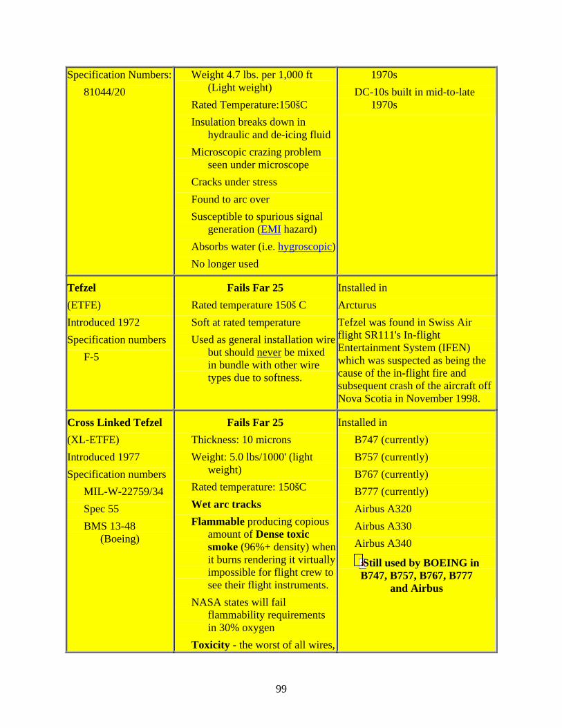
Specification Numbers: 81044/20
Weight 4.7 lbs. per 1,000 ft (Light weight)
Rated Temperature:150šC Insulation breaks down in
hydraulic and de-icing fluid Microscopic crazing problem
seen under microscope Cracks under stress Found to arc over Susceptible to spurious signal
generation (EMI hazard) Absorbs water (i.e. hygroscopic) No longer used
1970s DC-10s built in mid-to-late
1970s
Tefzel (ETFE) Introduced 1972 Specification numbers
F-5
Fails Far 25 Rated temperature 150š C Soft at rated temperature Used as general installation wire
but should never be mixed in bundle with other wire types due to softness.
Installed in Arcturus Tefzel was found in Swiss Air flight SR111's In-flight Entertainment System (IFEN) which was suspected as being the cause of the in-flight fire and subsequent crash of the aircraft off Nova Scotia in November 1998.
Cross Linked Tefzel (XL-ETFE) Introduced 1977 Specification numbers
MIL-W-22759/34 Spec 55 BMS 13-48
(Boeing)
Fails Far 25 Thickness: 10 microns Weight: 5.0 lbs/1000' (light
weight) Rated temperature: 150šC Wet arc tracks Flammable producing copious
amount of Dense toxic smoke (96%+ density) when it burns rendering it virtually impossible for flight crew to see their flight instruments.
NASA states will fail flammability requirements in 30% oxygen
Toxicity - the worst of all wires,
Installed in B747 (currently) B757 (currently) B767 (currently) B777 (currently) Airbus A320 Airbus A330 Airbus A340
Still used by BOEING in B747, B757, B767, B777
and Airbus
99

banned for manned aerospace use by major manufacturer. (Grumman Corp. banned it in 1982 and NASA followed suit in 1983 due to its toxicity)
Soft at rated temperature Loses mechanical strength
properties at rated temperature
Fails FAR 25 (airworthiness standards test)
Projected life 50,000 hrs Notch propagation problems
A Dangerous Wire
TKT (Teflon/Kapton/Teflon) Introduced 1992 Specification No:
MIL-W-22759 BMS 13-60
(Boeing)
Passes FAR 25 Weight: 5.0 lbs. per 1,000 ft
(Light weight) Arc-track resistant Abrasion resistant Superb insulation protection High heat tolerance Resists smoking when burning
(less than 2% density) Displays all the positive aspects
of Kapton (i.e. lightweight, resistance to burning, no fumes when burning etc) without any of Kapton's negatives. No Known Problems
Installed in B737s built after 1992 B757s built after 1992
Sources: Edward Block (IASA) Michael Murphy Patrick Price (deceased)
100
NOTES Only TKT wire has no known problems and meets FAR 25 requirements.
No specific standards spelt out by aircraft regulatory authorities such as US FAA or European JAR regarding aircraft electrical wire. Specifically no standards defined or any requirement to test wire for:
• Propensity of wire to wet or dry arc track • Propensity of wire to burn • The density of smoke and toxicity of fumes when wire burns
Modern jet transport aircraft are required by law (FAA 25 & JAR 25) to ensure all safety of flight items and aircraft systems have adequate backup systems installed in the event of a failure of the main system, (and that includes aircraft electrical systems), yet no thought was given to the failure of the aircraft wiring system itself.
Wire is deemed by most in the aviation industry (i.e. aircraft manufacturers, pilots, airline management and regulatory authorities) as an "install and forget" item. This attitude is best summed up by the comment of United States Federal Aviation Authority (FAA) deputy head, Tom McSweeny, who said on -- in -- "Wire is wire". This attitude ignores the fact that:
• Modern jet transport aircraft contain literally hundreds of kilometers of wire. • Wire is often damaged during manufacture and/or installation. • Wire is often incorrectly installed in aircraft. (i.e. incorrectly routed near hot
equipment and/or bundled together with other incompatible wire types such as soft wire laying adjacent hard wire etc)
• Wire (both the wire and its insulation) deteriorates with age. With regard to the insulation, it dries out, becomes brittle forming cracks exposing the conductor (i.e. wire) . Wire itself, oxidizes especially associated with the widespread electrolysis that occurs in aircraft leading to poor contacts and the generation of local hot spots in the wire which has the potential to melt the surrounding insulation material.
All wire deteriorates in service due to environmental factors such as: • extremes of heat & cold experienced by aircraft on the ground and in the air. (i.e. wire
can experience plus +200šC down to minus -70šC), • water damage, (hydrolysis and the fact that some wire types exhibit hygroscopic
tendencies) • salt damage associated with marine environments. (all aircraft operate into airfields
adjacent marine environments at least some time in their lives) • contamination by aircraft fluids such as fuel, oil, hydraulic fluid, deicing fluid,
cleaning chemicals, toilet residue, galley spillage etc. • in-flight vibration causing chafing of wires rubbing against other wires or the
structure of the aircraft. This is especially a problem with hard wire such as Kapton laying adjacent a soft wire like Tefzel.
101
• All wire products display differing properties with regard to aging, but practically all wire insulation material dries out, goes hard and then develops hairline fractures which allow the ingress of water and other aviation fluids leading to micro-discharges of current through the cracks to surrounding wires or the aircraft structure. ('ticking' faults)
• All aircraft use their airframe as their electrical earth return pathway resulting in significant constraints in the operation of protection devices such as circuit breakers located in the cockpit. (see separate paper on this issue)
FAR 25 states: "that insulation material can not be used that is hazardous, unreliable, or contributes smoke/fire." COMMENT by Ed Block: "No particular uses of insulation were further specified so insulation material includes; seat insulation, insulation blankets, rug insulation, acoustic and wire insulation. They are all types of insulation materials. Unless they are tested with an electrical fire (2,000 degrees) igniter to prove flammability proof, the material can not meet FAR 25 requirements. By their own (limited) standards, the FAA has said, in fact, that most types of wire cannot be used!" "Only TKT wire insulation (BMS 13-60) meets FAR 25 Standards."
102
VITA
SUSAN J. KIPTINNESS
Personal Data: Date of Birth: December 6, 1975 Place of Birth: Nairobi, Kenya Marital Status: Single Education: Moody Aviation, Elizabethton, Tennessee;
Aviation Technology, B.S., 2000 East Tennessee State University, Johnson City, Tennessee;
Engineering Technology, M.S., 2004 Professional Experience: Avionics Technician, Avionics America; Knoxville,
Tennessee, 2000-2001 Avionics Technician, Averitt Aviation; Sparta, Tennessee, 2001-2002 Graduate Assistant, East Tennessee State University, Department of Technology, 2002-2004
103