Embed Size (px)
Citation preview

AN ABSTRACT OF THE THESIS OF
Sushim Koshti for the degree of Master of Science in Mechanical Engineering presented on September 17, 2007. TITLE: Designing a Passenger Lift and Transfer Device Using 3D Modeling and Kinematic Simulation Techniques. Abstract approved:
_______________________________________________ Joseph R. Zaworski Transportation plays such an important role in daily living that, without it, a person
might be totally homebound. The nation’s air travel system for persons with
disabilities is an area of substantial dissatisfaction, with both passengers and the airline
industry recognizing the need for improvement. One of the major concerns of today’s
practices is that of manual dependant transfers. These transfers are injurious to the
airline staff, unsafe and undignified for the passengers, and are often a deterrent for
potential wheelchair bound passengers. The need to facilitate these dependant transfers
with a mechanical solution complies with human ethics and makes good business
sense. This project was undertaken to investigate the performance of various design
alternatives by means of 3D modeling and kinematic simulation. The various design
iterations were simulated in a virtual environment and their performance was studied.
The best design was the one with bent paddles, arms with 2 links having lengths 10”
and 12”, and telescoping type base-supports. From the simulation standpoint, this
project established and demonstrated the application of a procedure to aid in the
evaluation of designs of the transfer device.

© Copyright by Sushim Koshti
September 17, 2007
All Rights Reserved

Designing a Passenger Lift and Transfer Device Using 3D Modeling and Kinematic Simulation Techniques
by
Sushim Koshti
A THESIS
submitted to
Oregon State University
in partial fulfillment of the requirements of the
degree of
Master of Science
Presented September 17, 2007 Commencement June 2008

Master of Science thesis of Sushim Koshti presented on September 17, 2007.
APPROVED
Major Professor, representing Mechanical Engineering
Head of the School of Mechanical, Industrial & Manufacturing Engineering
Dean of the Graduate School
I understand that my thesis will become part of the permanent collection of Oregon
State University libraries. My signature below authorizes the release of my thesis to
any reader upon request.
Sushim Koshti, Author

ACKNOWLEDGEMENTS
I sincerely thank Dr. Kate Hunter-Zaworski and Dr. Joseph Zaworski for
giving me the opportunity to work with them and be a part of the National Center for
Accessible Transportation. This project would have been lacking without Dr. Joseph
Zaworski’s support and guidance. I also thank Dr. Kenneth Funk for counseling my
studies in Human Systems Engineering. Engaging myself in this discipline has helped
me broaden my horizons and hone my skills as a design engineer. I am very grateful to
Jon Mast for being a great colleague allowing creative ideas to evolve into productive
solutions. I am indebted to my parents and family for having faith in me and providing
constant encouragement in my pursuit for higher education. I would also like to thank
everyone else who has cheered me on through the years in my quest for success.

TABLE OF CONTENTS
Page
1. INTRODUCTION
1.1. Background on Disabilities and Challenges in Air Travel……………………1
1.2. The Manual Transfer Process and its Hazards………………………………...3
1.3. Overall Objectives of the Project……………………………………………...5
1.4. Proposed Solution……………………………………………………………..6
1.5. 3D Modeling and Kinematic Simulation……………………………………...8
1.5.1. 3D Modeling…………………………………………………………….8
1.5.2. Kinematic Simulation………………………………………………….10
1.6. Summary……………………………………………………………………..13
2. BACKGROUND
2.1. Existing Transfer Methods…………………………………………………...14
2.1.1. Manual Transfer………………………………………………………..14
2.1.1.1. Biomechanics Study……………………………………………...14
2.1.1.2. NCAT Computer Survey……………………………………...…16
2.1.2. Patient Transfers in Healthcare…………………………………...........18
2.1.3. Alternative Transfer Methods………………………………………….20
2.1.3.1. Haycomp…………………………………………………………21
2.1.3.2. Xpiration…………………………………………………………22
2.1.3.3. Existing Patents…………………………………………………..23

TABLE OF CONTENTS (Continued)
Page
2.2. Previous Work at NCAT……………………………………………………..31
2.2.1. Mr. Wörz’s Work……………………………………………………...32
2.2.2. Current Design…………………………………………………………35
2.3. Project Objectives……………………………………………………………43
3. MATERIALS AND METHODS
3.1. CATIA……………………………………………………………………….45
3.2. Modeling Data………………………………………………………………..48
3.2.1. Seats……………………………………………………………………48
3.2.2. Aircraft Body…………………………………………………………..49
3.2.3. Virtual Aircraft…………………………………………………………50
3.2.4. Tony the Passenger……………………………………………….……51
3.2.5. Path-of-Transfer……………………………………………………......52
3.2. Kinematic Model……………………………………………………………..53
3.4. Experimental Procedure……………………………………………………...57
3.4.1. Paddles…………………………………………………………………58
3.4.2. Arms……………………………………………………………………61
3.4.3. Base-Supports………………………………………………………….63
4. RESULTS
4.1. Paddles……………………………………………………………………….65

TABLE OF CONTENTS (Continued)
Page
4.2. Arms………………………………………………………………………….68
4.3. Base-Supports………………………………………………………………..79
5. DISCUSSION
5.1. Paddles……………………………………………………………………….86
5.2. Arms…………………………………………………………………………87
5.3. Base-Supports………………………………………………………………..90
5.4. Transfer Device………………………………………………………………92
6. CONCLUSION
6.1. Limitations of this Project……………………………………………………93
6.2. Suggestions for Future Studies………………………………………………94
6.3. Suggestions for Future Designs……………………………………………...95
6.4. Overall Project Summary…………………………………………………….96
BIBLIOGRAPHY…………………………………………………………………….97
LIST OF FIGURES
Figure Page
1. Manual Transfer Process……………………………………………...…………......3
2. CATIA model of the proposed solution…………………………………...………...8
3. Experimental Setup for Biomechanics study…………………………………..…..15 4. Variations in techniques used the Biomechanics study……………………………16 5. Transfer experience of passengers requiring a transfer between wheelchair and airplane seat…………………………………………………………….……..18 6. SureHands……………………………………………………………….……........20 7. Haycomp Eagle 2 Passenger Hoist………………………………………………...21 8. Xpiration Boarding Chair…………………………………………………….........22 9. Travel Insert Chair (US Patent 4,113,307)…………………………………..…….24
10. Easy Transport Chair (US Patent 5,769,360)………………………………….….25
11. Device for moving a disabled person (US Patent 5,579,546)…………………….26
12. Wheelchair and platform device for moving a disabled person (US Patent 5,669,620)…………………………………………………………….27 13. Setup for using the apparatus (Front View) (US Patent 2006/0082210 A1)……..28
14. Apparatus in use (Top View) (US Patent 2006/0082210 A1)………………..…..28
15. Lift and Transfer apparatus for disabled person (US Patent 6,119,287)…….…....29
16. Patient transfer Apparatus (US Patent 3,940,808)…………………………..……30
17. Mr. Wörz with his first prototype……………………………….…………..……32 18. Conceptual Drawings of Designs Similar to SureHands………………..………..33 19. Mr. Wörz with his second prototype…………………………..………..………...34 20. Wooden Prototype……………………………………………………...…………36

LIST OF FIGURES (Continued)
Figure Page
21. First Prototype Of The Transfer Device………………………………...………..37 22. Nylon Strap Arrangement …………………………………………………...…...38 23. Pneumatic Arrangement for Arms………………………………………………..40
24. Second Prototype of the Transfer Device………………………………………...42
25. Aircraft Seats……………………………………………………………………..48
26. Aircraft Body……………………………………………………………………..49
27. Virtual Aircraft……………………………………………………………………50
28. Tony the Manikin…………………………………………………………………51
29. Path-of-Transfer…………………………………………………………………..52
30. Prismatic joint in Kinematic Model………………………………………………53
31. Revolute Joint 1 in Kinematic Model……………………………………….........54
32. Revolute Joint 2 of Kinematic model……………………………………….........55
33. Revolute Joint of Kinematic Model………………………………………………56
34. Components of the Transfer Device……………………………………………...57
35. CATIA Reporting Interference…………………………………………………...59
36. Sequence of Transfer from Aisle Chair to Aircraft Seat………………………….60
37. Paddles Design 1…………………………………………………………….........65
38. Paddles Design 2…………………………………………………………….........66
39. Paddles Design 3………………………………………………………………….67
40. Arms Design 1……………………………………………………………………69

LIST OF FIGURES (Continued)
Figure Page
41. Result window from CATIA showing minimum distance between Tony and the front Seats…………………………………………………….........70 42. Result window from CATIA showing minimum distance between Tony and Overhead Bins…………………………………………………..……...71 43. Distance of Base from front face of front seat………………………………..…..72
44. Arms Design 5……………………………………………………………………77
45. Nomenclature for the seats…………………………………………………..........79
46. 4-Bar Mechanism for Supports…………………………………………………...80
47. 4-Bar Mechanism in Extended position……………………………………..........80
48. Basic dimensions of the Wing mechanism………………………………….........81
49. Wing mechanism in operating and extended positions…………………………...82
50. Basic Dimensions of the Horizontal-Wing mechanism…………………………..83
51. Horizontal-Wing mechanism in operating and extended positions………………83
52. Basic Dimensions of the Telescoping mechanism………………………………..84
53. Telescoping mechanism in retracted and extended positions……………….........85

LIST OF TABLES
Table Page
1. Design Configurations for Arms…………………………………………………...68

Designing a Passenger Lift and Transfer Device Using 3D Modeling and Kinematic Simulation Techniques.
1. INTRODUCTION
1.1. Background on Disabilities and Challenges in Travel
Historically, society has tended to isolate and segregate individuals with
disabilities. Despite some improvements, such forms of discrimination against
individuals with disabilities continue to be a serious and pervasive social problem.
Unlike individuals who have experienced discrimination on the basis of race, color,
sex, national origin, religion, or age, individuals who have experienced discrimination
on the basis of disability have often had no legal recourse to redress such
discrimination (United States Department of Justice, 1990). The Americans with
Disabilities Act (ADA) of 1990 includes a legal definition of disability, in part
defining a person with a disability as one who has “a physical or mental impairment
that substantially limits one or more major life activities”. The ADA provides
guidelines that assure the provision of services to people with disabilities and the
protection of their legal rights. It also prohibits discrimination on the basis of disability
in employment, access to public services, public accommodations, and commercial
facilities.
Transportation plays such an important role in daily living that, without it, a
person might be totally homebound. A new Bureau of Transportation Statistics survey

2
found that nationally, almost 15 million people in this country have difficulties getting
the transportation they need. Of these, about 6 million (40 percent) are people with
disabilities. More than 3.5 million people in this country never leave their homes. Of
these, 1.9 million (54 percent) are people with disabilities. About 560,000 disabled
people indicate they never leave home because of transportation difficulties (Bureau of
Transportation Statistics, 2003). The aging of national populations is another major
factor in the increasing number of people who are transportation-disabled resulting in
the growing demand for accessible transportation systems. It is estimated that world-
wide there are now 472 million people over 65 years of age; by 2020 this number will
increase by 50% to more than 707 million (International Center for Accessible
Transportation: Background). These numbers are growing at a significantly higher rate
than that of the general population and it represents an increasing segment of the travel
market. Any intelligent transportation system must be universally accessible or it
would fail to provide the level of service to meet this demand. Not only does striving
for accessibility comply with human rights, safety, security and quality of life, but it
also makes good business sense.
For years, access to the nation’s air travel system for persons with disabilities
was an area of substantial dissatisfaction, with both passengers and the airline industry
recognizing the need for major improvement. In 1986 Congress passed the Air Carrier
Access Act, requiring the Department of Transportation (DOT) to develop new
regulations which ensure that persons with disabilities will be treated without
discrimination in a way consistent with the safe carriage of all passengers. These
3
regulations were published in March 1990 and represented a major stride forward in
improving air travel for persons with disabilities. Despite such efforts to facilitate
improved air travel for passengers with disabilities, transfers occurring between a
wheelchair and an aircraft seat are still a major source of injury for both the passenger
and the people assisting the transfer.
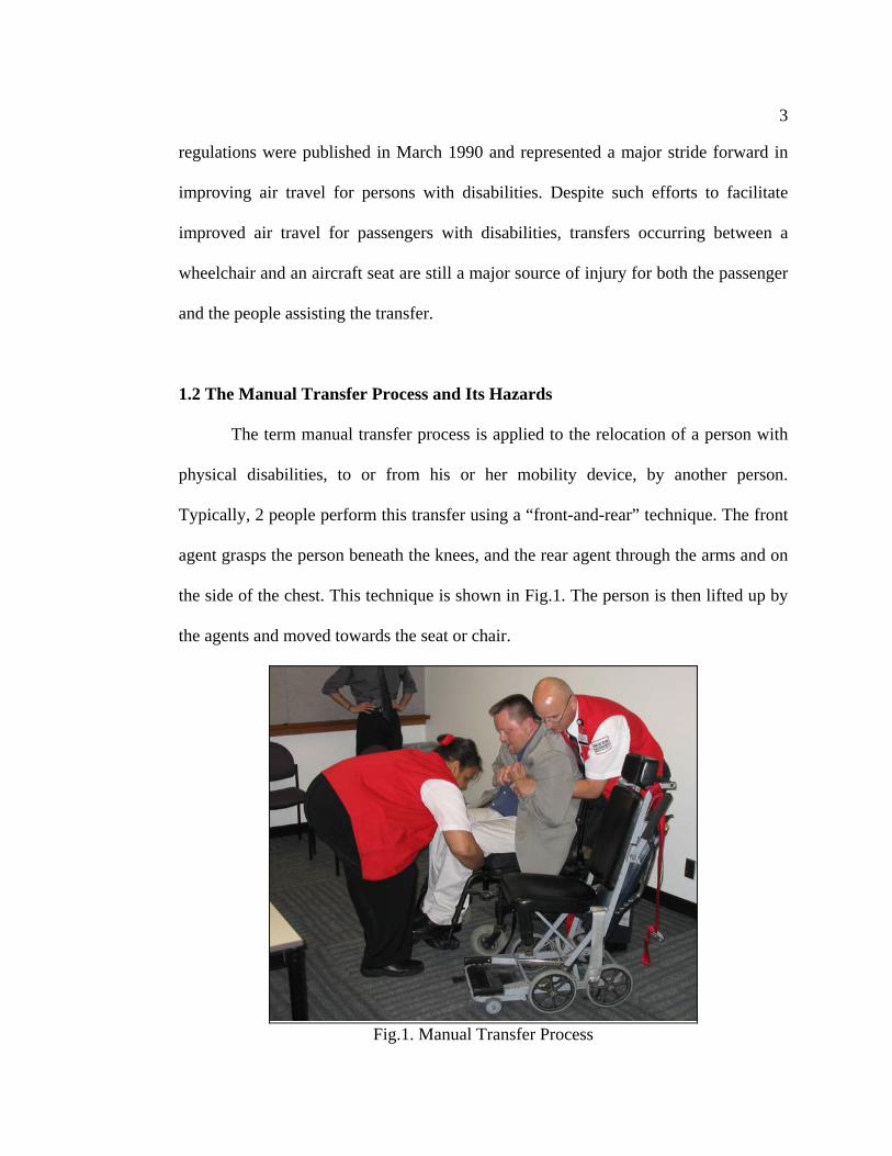
1.2 The Manual Transfer Process and Its Hazards
The term manual transfer process is applied to the relocation of a person with
physical disabilities, to or from his or her mobility device, by another person.
Typically, 2 people perform this transfer using a “front-and-rear” technique. The front
agent grasps the person beneath the knees, and the rear agent through the arms and on
the side of the chest. This technique is shown in Fig.1. The person is then lifted up by
the agents and moved towards the seat or chair.
Fig.1. Manual Transfer Process

4
When a person in a wheelchair wants to board an airplane, a manual transfer
process is indispensable. After arriving at the end of the jet bridge, the wheelchair
bound person is transferred to an aisle chair. An aisle chair is basically a wheelchair
narrow enough to move through the aisles of an airplane. The aisle chair, with the
person in it, is then rolled into the aircraft to the appropriate seat and the person is
transferred to the seat. This routine is repeated, in reverse, at the destination. Thus, it
takes four manual transfers per person per journey. Apart from these, manual transfers
are also required for a person with disabilities to use the onboard lavatory.
Not only do these transfers expose the traveler to the risk of being roughly
handled, dropped and embarrassed, but also expose the transferors to to the risk of
developing a disabling lower-back injury. Amongst those who perform such transfers
regularly, lower-back disorders caused due to lifting and transferring, are common
(Harber et al., 1985).
It is evident from the above discussion that an alternative transfer technique is
called for. A good technique would remove the risks associated with the transfer and
also increase freedom of the persons with disabilities onboard an aircraft. It is
expected that this will also increase the number of travelers with disabilities, thus
promoting air travel for persons with disabilities and business for the airlines.

5
1.3 Overall Objectives of the Project
The Air Carrier Access Act clearly explains the responsibilities of the traveler,
the carriers, the airport operators, and contractors, who collectively make up the
system which moves over one million passengers per day. The Air Carrier Access
rules are designed to minimize the special problems that travelers with disabilities face
as they negotiate their way through the nation’s complex air travel system from origin
to destination.
Listed below are the relevant rules from the Air Carrier Access Act (United
States Department of Transportation, 1990):
“A carrier may not refuse transportation to a passenger solely on the basis of a disability. Properly trained service personnel who are knowledgeable on how to assist individuals with a disability in boarding and exiting must be available if needed. For aircraft with 30 or more passenger seats, at least one half of the armrests on aisle seats shall be movable to facilitate transferring passengers from on-board wheelchairs to the aisle seat. Aircraft with more than 60 seats must have an operable on-board wheelchair if there is an accessible lavatory, or a passenger provides advance notice that he or she can use an inaccessible lavatory but needs an on-board chair to reach it. Air carrier personnel shall assist a passenger with a disability to move to and from seats as a part of the boarding and exiting process. Air carrier personnel shall assist a passenger use an on-board wheelchair when available to enable the passenger to move to and from the lavatory. Air carrier personnel shall assist a passenger move to and from the lavatory, in the case of a semi-ambulatory person (as long as this does not require lifting or carrying by the airline employee).

6
If the plane has fewer than 30 seats, the carrier may refuse transportation if there are no lifts, boarding chairs or other devices available which can be adapted to the limitations of such small aircraft by which to enplane the passenger. Airline personnel are not required to carry a mobility-impaired person onto the aircraft by hand. Carrier personnel are not required to provide assistance inside the lavatory.”
It can be observed that the rules of the Air Carrier Access Act are influenced by
the current system of manual transfers. The guidelines protect the carrier personnel by
not requiring them to provide assistance in many situations. Clearly, a better process
will be beneficial to both the carrier and the passengers.
The overall objectives of this project at NCAT are to design a mechanical device
to facilitate the transfer process by reducing the risks of injuries and increasing the
safety and comfort of the passenger and airline personnel. This will benefit the airlines
by reducing passenger complaints and law suits. This device will facilitate the transfer
process without hurting the dignity of the passengers. The proposed solution will also
be favorable to the airline personnel by being easy to operate and asking minimal
physical effort. It is expected that this device will encourage persons with disabilities
to travel more and hence benefit them as well as the industry.
1.4 Proposed Solution
The proposed mechanical solution is similar to the manual transfer process.
The reason behind this is the shortcomings of the other devices already available in the

7
market. These devices are discussed in detail in section 2.1.3. As seen previously in
section 1.2, in the manual transfer process one agent holds the passenger under the
arms on the sides of the chest and the other supports the thighs. The proposed
mechanical solution will also involve “arms” which hold the passenger on the sides of
the chest and have leg-supports to support the thighs. The device will have a lifting
mechanism to lift and lower the passenger, for example, from the chair to the seat and
back.
The device will also have to take into account the limited space available in
aircraft. The device in itself will not present a hazard to the passenger and airline
agent. The device will be easy to operate and will demand little physical and
intellectual effort from the agent. Human Factors guidelines will be applied to the
device to facilitate the above.
A 3D model of the proposed solution is illustrated in Fig.2.

8
Fig.2. CATIA model of the proposed solution
1.5 3D Modeling and Kinematic Simulation
Engineering design is a creative activity, where the skills of the designer are
used with the help of the engineering knowledge he/she has acquired to produce the
design of an engineering system (Krishnamoorthy et al., 2005). The advances in
computer science and technology have resulted in the emergence of very powerful
hardware and software tools that offer scope for use in the entire design process
resulting in improvement in the quality of the design.
1.5.1 Computer Aided Design (CAD)
Computer Aided Design (CAD) is a process where the designer and the
computer work together to produce engineering designs. CAD is sometimes translated

9
as "computer-assisted drafting", "computer-aided drafting", or a similar phrase.
Related acronyms are CADD, which stands for "computer-aided design and drafting",
CAID for “computer-aided industrial design” and CAAD, for "computer-aided
architectural design". All these terms are essentially synonymous, but there are a few
subtle differences in meaning and application. CAD was originally the three letter
acronym for "Computer Aided Drafting" as in the early days CAD was really a
replacement for the tradition drafting board. But now the term is often interchanged
with "Computer Aided Design" to reflect the fact that modern CAD tools do much
more than just drafting.
Computer aided design has evolved from the simple replacement of traditional
drafting equipment to a very sophisticated, highly visual design tool. The earlier CAD
programs used the computer to generate lines for 2D drawings. As the software and
hardware advanced, these 2D drawings could be converted into 3D objects that the
computer recognized as having height, width, and depth. The software used to create
these earlier 3D objects was still 2D based; they originated from and were primarily
used to draw in two dimensions. Modern software used for solid modeling often
functions in the reverse order; the three-dimensional object is drawn and then two-
dimensional, orthographic drawings are generated from that model.
Advantages of wireframe 3D modeling over exclusively 2D methods include
but are not limited to:

10
• Flexibility, ability to change angles or animate images with quicker rendering
of the changes;
• Ease of rendering, automatic calculation and rendering photorealistic effects
rather than mentally visualizing or estimating;
• Accurate photorealism, less chance of human error in misplacing, overdoing,
or forgetting to include a visual effect.
1.5.2 Kinematic Simulation
A simulation is an imitation of the real thing. It refers to a broad collection of
methods and applications to mimic the behavior of real systems, usually on the
computer with appropriate software (Kelton et al., 2007). Kinematic simulation is the
process of modeling kinematic systems and then simulating it in the suitable
environment under the appropriate constraints.
Discussed below are features of the DMU Kinematics Simulator available with
the software CATIA (Computer Aided Three-dimensional Interactive Application) as
advertised on its website (IBM Software: CATIA).
3D mechanisms:
3D mechanisms based on 16 types of joints are available: Revolute, Prismatic,
Cylindrical/Actuator, Planar, Rigid, Spherical, Universal, Point-Surface, Point-Curve,
Roll-Curve, Slide-Curve, Screw, Gear, Rack, Cable and Constant Velocity joints. For
most of joint types, the created mechanism can be associated to the joint type. It is

11
possible to define and verify joint limits (travel limits or joint stops) and thus guiding
the design of the assembly.
Automatically generates mechanism:
Constraints defined in CATIA Assembly Design product can be automatically
interpreted as joints.
Simulates mechanism motion:
Users can easily simulate motion using the mouse, and guide possible actions thanks
to a co-pilot which pops up icons under the mouse. Users can also create a wide range
of kinematics laws allowing time-based simulation. The laws can be graphically
visualized.
Analyzes mechanism motion dynamically:
During mock-up design review, the designer can not only view simulated kinematics
motion but also analyze the mechanism's consistency with the functional
specifications. DMU Kinematics Simulator 2 (KIN) performs interference and
clearance checking as well as computing the minimum distance. A 'stop on collision'
option freezes the motion for detailed analysis.
Records motion analysis' results:
Users can replay a motion simulation, or save it as a video file.
Generates useful information:
DMU Kinematics Simulator 2 (KIN) provides the ability to define a point in a moving

12
part and generate its trace in order to design cams. Users can also generate the swept
volume of a moving part that is defined by a part moving through its entire range of
motion. The swept volume can be reused in the clash analysis to check, during the
digital mock-up evolution, that the mechanism can still be operated. During a
simulation with laws, it is possible to plot sensors according to time but this
functionality also offers the possibility to plot a sensor according to another sensor.
This ability enhances the study of a mechanism offering a better way to qualify its
behavior, or to improve its design. Users can run, for instance the simulation of an
engine, and plot the position of an inlet valve according to the rotation of the
crankshaft.
Allows automation of mechanism creation and simulation through Visual Basic macro
programming:
Multiple combined simulations are possible for advanced digital product synthesis
when using this product in conjunction with other DMU products. For example, users
can simulate and synchronize un-mounting procedures with a kinematics motion when
both the DMU Kinematics Simulator and DMU Fitting Simulator products are
installed.
Simulates mechanisms:
The data used to create the full digital mock-up may come from any number of
supported data formats, including: CATIA, STL, IGES, OBJ (from Wave front) or
other multi-CAD environments. The kinematics simulation and associated kinematics
analysis functions are identical whatever data format is used.
13
Looking at the above features, one can perceive the potential of 3D modeling
and kinematic simulation. If made an integral part of the design process, it can be used
effectively in the testing and evaluation stages. It has the ability to replace physical
prototypes and make the design process not only cheaper but also faster and more
flexible.
1.6 Summary
A significant number of people with disabilities never leave their home
because of transportation difficulties. An even higher population is expected to face
similar difficulties in the near future. Clearly the existing infrastructure does not
promote air travel amongst persons in this population. There is a perceptible demand
and need to improve air travel for persons with disabilities. Such a change can
significantly improve the standard of living of this population and also increase
business for the airlines. Techniques such as 3D modeling and kinematic simulation
aid the design process by reducing the cycle time during the prototyping, testing and
redesign stages.

14
2. BACKGROUND
2.1 Existing Transfer Methods
The various transfer methods practiced today in various scenarios are
discussed in this section.
2.1.1 Manual Transfer
As discussed before, the term manual transfer process is applied to the
relocation of a person with physical disabilities to or from his or her mobility device.
These transfers require 2 people using the “front-and-rear” technique. The front agent
grasps the person beneath the knees, and the rear agent, through the arms and on the
side of the chest. The person is then lifted and moved towards the seat. There are
many risks associated with such a transfer. A biomechanics study and computer
survey discussed further, highlight a few of them.
2.1.1.1 Biomechanics Study
A biomechanics study, conducted by Dr. Michael Pavol at Oregon State
University, looked at the risk factors for injury during manual transfers on an aircraft.
The purpose of this study was to determine the influence of spatial constraints of an
aircraft interior and the size of the traveler on the likelihood of injury to transferors
and the traveler.
15
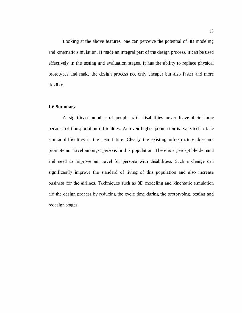
Two-person manual transfers were performed by healthy men and women who
had no prior experience in conducting such transfers. The transfers were conducted in
a laboratory simulation of an aircraft interior which included economy-class airplane
seats mounted to the floor with armrests raised. Fig.3. shows the experimental setup of
the transfer and Fig.4. shows the variations in techniques used.
Fig.3. Experimental Setup for Biomechanics Study.

16
Fig.4. Variations in Techniques Used the Biomechanics Study.
The study observed consistent effects of spatial constraints, transfer direction and
traveler size.
The front transferor was placed at a higher risk of injury because of the
constraints imposed by the seat in front of the traveler. This seat more than
doubles the risk for the front transferor and thus represents a factor
contributing towards the safety of a transfer.
Similarly the back seat imposes constraints on the back transferor, and is thus,
another factor contributing towards the safety of a transfer.
Traveler size had large effects on the lower-back loading of both the
transferors.
Thus, the results strongly recommend elimination of the need to manually transfer a
person.
2.1.1.2 NCAT Computer Survey
The National Center for Accessible Transportation conducted a computer
survey in 2005 to probe the air-travel experience of passengers that must use an aisle
17
chair. The survey received more than 300 responses in addition to comments by many
of the participants. The questionnaire asked users to rate both their experience during
the routine of a manual transfer and the features of the aisle chairs used during the
transfer. For the manual transfer routine, the responses varied from a 1 for ‘excellent’
to a 5 for ‘terrible’ and for the features of the aisle chair, they varied from a 1 for ‘very
good’ to a 5 for ‘must be improved’.
Fig.5. shows the progression of the satisfaction with the various transfer
processes. The horizontal axis represents the independence level of the passengers
with 1 corresponding to fully independent and 5 to fully dependant. The trend clearly
shows a need for improvement in the transfer process. The responses also indicated
significant dissatisfaction with the aisle chair in terms of the straps used, footrest, chair
size and seat cushion, amongst others.

18
Transfer Experience
1
2
3
4
5
1 2 3 4 5
Level of Independence [1=Fully independant; 2=Fully Dependant]
Rat
ing
[1=e
xcel
lent
; 5=t
errib
le]
1st transfer to aisle chairtransfer to seat2nd transfer to aisle chairtransfer back to wheelchair
Fig.5. Transfer experience of passengers requiring a transfer between wheelchair and
airplane seat. 2.1.2 Patient Transfers in Healthcare
Similar to the travel and tourism industry, manually lifting and transferring a
patient with disabilities is a high-risk task in the healthcare industry as well. Nursing
staffs have one of the highest incidences of work-related back problems of all
occupations (Cust et al., 1972). Direct and indirect costs associated with back injuries
are estimated to be between $24 billion and $64 billion annually, with $20 billion of
that attributed to the health care industry (Safe Patient Handling and Movement,
2001). Over three quarters of a million working days are lost annually as a result of
back injuries in nursing (Stubbs, Buckle, Hudson, & Rivers, 1983), with an estimated
40,000 nurses reporting illnesses from back pain each year (Garrett et al., 1992).

19
Transferring a patient can take place in various environments in the health care
industry. These transfers include transferring a patient from a chair-to-toilet and back,
chair-to-bed and back, and chair-to-bathtub and back, amongst others. In most of these
cases, there is ample space available to facilitate the use of various lifting and
transferring devices. Discussed below is one such device, SureHands. The next
section, alternative transfer methods, includes a few more such devices.
SureHands
This lifting-device (Fig.6) developed by the SureHands company (SureHands) is used
at diverse places for lifting and transferring people with disabilities, e.g. wheelchair,
bedroom, restroom or even at pools. The product design is very simple. It consists of
two arms of bent steel pipe, pivoted directly above the person. At the lower end of the
arms, two cushions of solid synthetic foam are fixed, holding the person. Two steel
hooks are located on the upper end. These rather long hooks lead back to the center,
where they can be linked to any kind of hoist. The user’s legs are supported by two
curved pieces that are flat and have been coated with a soft plastic. These coated
supports are fixed to the pipes through adjustable belts. In that way the vertical
distance between supports and pipes can be adjusted. In addition, the belts can be
moved on the horizontal part of the pipes, making the SureHands device adjustable to
people of different sizes.

20
The SureHands device has to be used with a lifting device such as a hydraulic
jack or an overhead track which allows transfer between rooms and over flights of
stairs. This prohibits its use in confined spaces such as those in aircraft.
Fig.6. SureHands
2.1.3 Alternative Transfer Methods
Apart from the manual transfer process, there exist many devices which
provide an alternate method of performing a transfer. These devices have been
designed for performing transfers in various settings, such as hospitals, swimming
pools, cars, and public modes of transportation such as buses and airplanes. Discussed
further are a few such devices.

21
2.1.3.1 Haycomp
The Haycomp Eagle 2 is an aircraft passenger hoist for passengers requiring
full assistance. This device has been designed to transfer passengers to and from
wheelchairs and starboard side aisle seats of an aircraft. It can be used on a B717 and
larger Boeing and Airbus aircrafts (Haycomp Products: Eagle 2). The transfer process
starts outside the aircraft, where the person in the wheelchair wheels into place inside
the frame of the lift. A sling is placed underneath the passenger and then attached to
the arms on the Eagle 2. The passenger is then lifted off of the wheelchair with the
help of an electrical lift. The device, with the passenger in the sling, is rolled into the
aircraft and positioned such that the passenger in the sling is above a starboard side
aisle seat. The passenger is then lowered onto the seat and the sling is removed from
underneath the passenger. This process is repeated in reverse while de-boarding the
aircraft.
Fig.7. Haycomp Eagle 2 Passenger Hoist

22
This device has a few limitations. Due to its inherent design, it can be used
only on the starboard side aisle seats in an aircraft. The other, more important,
limitation is that it uses a sling to lift and carry a person. While a sling is an effective
way of carrying a person, it invades the personal space of the passenger because of its
need to be positioned underneath the passenger and then similarly removed.
2.1.3.2 Xpiration (XP Equipment: XP Boarding Chair)
The XP BoardingChair combines a hoist and an aisle chair. The hoist utilizes a
sling to lift the passenger of the wheelchair and place him/her onto the seat of the XP
BoardingChair. The chair is the rolled into the aircraft and the passenger is lifted off
of the seat of the XP BoardingChair to the seat of the aircraft. While this device is a
simple and safe alternative to the manual transfer process, the sling necessitates the
invasion of the personal space of the passenger.
Fig.8. Xpiration Boarding Chair
23
2.1.3.3 Existing Patents
There exist many devices which make an effort at facilitating the transfer
process. Though a few of these show some potential, most of the devices still neglect
important factors like comfort and physical limitations of the persons with disabilities.
In this section, a few such devices are discussed.
The existing devices can be divided according to the basic principle used in achieving
the
Chair/Seat
Sling
Sliding Surface
Hoist
Transfer stand

24
Travel Insert Chair and method of transporting the physically handicapped.
US Patent 4,113,307
Fig.9. Travel Insert Chair
This apparatus aims at being used as a transportation device for moving the
persons with disabilities at public transport facilities from the terminal to the
bus/airplane and between buses/airplanes. Though it will require an initial and final
transfer, this device significantly reduces the number of transfers that would be carried
out otherwise. But it cannot be used in places which do not have a large enough space
in front of the seat to be able to maneuver the chair in place. As a result it cannot be
used effectively in airplanes.

25
Easy Transport Chair.
US Patent 5,769,360
Fig.10. Easy Transport Chair
This device is similar to the previous one. It uses a seat already a part of the
bus/airplane. This seat is modified by making it detachable from the other seats in the
row and adding wheels to it. This seat can then be rolled out of the bus/airplane, be
occupied by the passenger and be rolled in again. It can then be reattached in its
original place. Though this removes the requirement of a transfer in the bus/airplane, it
still requires an initial and final transfer into and out of the seat. Also, the aisles in the
airplanes being very narrow will not accommodate movement of a seat.

26
Device for moving a disabled person.
US Patent 5,579,546
Fig.11. Device for Moving a Disabled Person.
This device utilizes a canvas rectangular-shaped sling for lifting a person. It
includes 2 pairs of hand grips, one on each side for holding and lifting the sling. These
hand grips can be removed and the sling can be attached to a conventional patient lift
sling. This device is simple and inexpensive to manufacture. But it does not address
the issue of intimacy in that the agents will have to put the sling under the person. This
is a common problem with all sling-type devices.

27
Wheelchair and platform device for movement of a disabled person from a wheelchair
to a chair seat support in a vehicle or aircraft.
US Patent 5,669,620
Fig.12. Wheelchair and Platform Device for Moving a Disabled Person
This transfer mechanism permits the person on the seat and the seat to move
laterally. The seat is on a platform that has a base and 2 laterally movable platforms.
The bottom of the seat has 2 tracks that are matched to and engage a track on a fixed
seat frame such as a seat on an aircraft. This would require at least a few seats to be
modified on all airplanes.

28
Method and means for assisting a person to, into and out of a seat in a confined space.
US Patent 2006/0082210 A1
Fig.13. Setup for Using the Apparatus (Front View)
Fig.14. Apparatus in Use (Top View)
This apparatus comprises inflatable structures for positioning on seats and a
rigid transfer means supported on top of the structures. It has primarily been made to
overcome difficulties experienced by disabled passengers on an aircraft while
transferring to a seat not easily accessible from the aisle, such as the window seat.
29
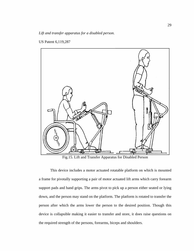
Lift and transfer apparatus for a disabled person.
US Patent 6,119,287
Fig.15. Lift and Transfer Apparatus for Disabled Person
This device includes a motor actuated rotatable platform on which is mounted
a frame for pivotally supporting a pair of motor actuated lift arms which carry forearm
support pads and hand grips. The arms pivot to pick up a person either seated or lying
down, and the person may stand on the platform. The platform is rotated to transfer the
person after which the arms lower the person to the desired position. Though this
device is collapsible making it easier to transfer and store, it does raise questions on
the required strength of the persons, forearms, biceps and shoulders.

30
Patient transfer apparatus.
US Patent 3,940,808
Fig.16. Patient Transfer Apparatus
This transfer apparatus is comprised of a wheeled base having a vertical
column mounted on it. The column is vertically slideable and has a pair of arms
extending from it. A third arm extends upwards and then outwards in a position
between the pair of arms. These 3 arms support a chair for transferring the person.
This chair has 4 flaps which fold out to be positioned flat on a bed, and fold in to take
the shape of a chair. To use this device, the seat portion of the chair is positioned
below the person and the other flaps are then sequentially folded in during the transfer.
To place the person, the chair is positioned in the required spot and the flaps are then
folded out and the chair is slid from underneath the person. This mechanism is similar
31
to a flexible sling used to transfer a person and hence has the drawback of invading the
personal space of the passenger.
2.2 Previous NCAT Work
2.2.1 Mr. Wörz’s Work
Ulrich Wörz, a graduate student working with the National Center for
Accessible Transportation started the process of developing a mechanical aid to
facilitate the transfer process. In the two years he spent at OSU in this pursuit, he
developed and investigated the performance of a few prototypes. The first device held
a person under the arm pits and had supports for the feet. The second device was a
more complex scissor-like mechanism which grasped the person on the sides of the
chest by using the weight of the person being lifted up.
The first prototype is as shown in Fig.17. It consists of 2 rigid arms extending
from a vertical column. The horizontal arms had a curve at the end which was padded
with a cushioning material. This curved region was placed under the arm pits of the
person being lifted up. The vertical column had supports at the bottom to support the
feet of the person. The device was lifted up using an overhead hoist. The overhead
hoist could be replaced by another lifting mechanism like a hydraulic jack or a
telescoping actuator by making a few changes to the device. The device thus had the
capability to be used in an aircraft where overhead space is limited.
32
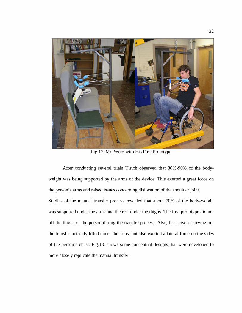
Fig.17. Mr. Wörz with His First Prototype
After conducting several trials Ulrich observed that 80%-90% of the body-
weight was being supported by the arms of the device. This exerted a great force on
the person’s arms and raised issues concerning dislocation of the shoulder joint.
Studies of the manual transfer process revealed that about 70% of the body-weight
was supported under the arms and the rest under the thighs. The first prototype did not
lift the thighs of the person during the transfer process. Also, the person carrying out
the transfer not only lifted under the arms, but also exerted a lateral force on the sides
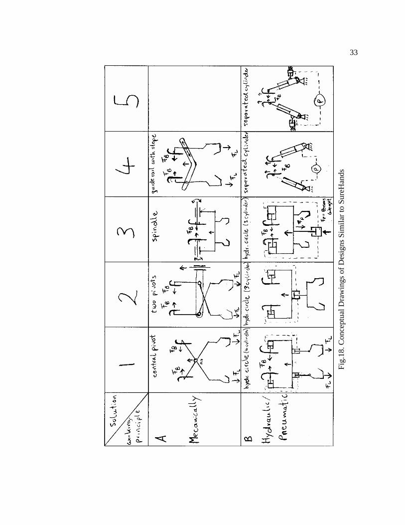
of the person’s chest. Fig.18. shows some conceptual designs that were developed to
more closely replicate the manual transfer.
33
Fig.
18. C
once
ptua
l Dra
win
gs o
f Des
igns
Sim
ilar t
o Su
reH
ands

34
A second prototype was built following the idea of concept 1. To exert the
lateral force, a scissor-like mechanism was explored. This mechanism exerted a lateral
force on the arm-end proportional to the weight supported on the leg-end. It had the
potential to eliminate the need of an external energy source for the lateral force. The
second prototype was developed using this mechanism and paddles and leg hooks to
support the chest and thighs of the person being lifted up (Fig.19).
Fig.19. Mr. Wörz with His Second Prototype
35
Tests on this device showed that the device worked well without inducing any
pain on the arms of the person. Thus, an acceptable grasping technique, that of
applying a lateral force on the sides of the chest and supporting the thighs, was
determined. But this mechanism does not take account of the horizontal motion
required to transfer a person from the chair to seat. The prototypes developed by Mr.
Wörz used an overhead hoist for lifting purposes. Due to the inadequate overhead
space available in airplanes, a mechanism which could lift the device from below is
desired. Further development has since been done to design a solution for these
challenges.
2.2.2 Current Design
After the encouraging results obtained by Mr. Wörz through his work on the
transfer process, additional work has been done in the grasping, lifting and moving
mechanisms. Since the grasping technique used by Mr. Wörz in his second prototype
worked well, it was decided to use a similar technique. A new design for the grasping
mechanism which consisted of 2 arms which, when placed under the arm pits of a
person held the person on the sides of the chest, was developed. These arms are
horizontal and have paddles at the ends to maximize the comfort of the person being
transferred. To aid the horizontal motion of the person, these arms are connected to a
vertical column through a 2-link mechanism. The vertical column supports a sleeve
which is free to move along the column. The sleeve can be moved up and down with a
hydraulic jack.

36
A wooden prototype was made to investigate the operation of the 2-link
mechanism of this device (Fig.18). This prototype was then positioned adjacent to
airplane seats, as it would be when used during a transfer. It appeared viable to
transfer a person to the aisle seat in an airplane. The results were promising and it was
decided to make a working prototype which would be able to lift and transfer a person.
Fig.20. Wooden Prototype

37
Since this prototype was to be used in the NCAT laboratory for study purposes
only, weight and space were not a constraint. Fig.21 shows the finished version of this
working prototype.
Fig.21. First Prototype of the Transfer Device
The arms are similar to the wooden prototype and have ergonomic paddles to
maximize the comfort of the person being transferred. The 2 arms are connected by a
horizontal crossbar at the other end. The arms support 2 leg hooks to lift underneath a
person’s thighs. These leg hooks hang from the arms using nylon straps. The crossbar

38
is connected to a 3-link mechanism. The 2-link mechanism was replaced by a 3-link
mechanism to attempt a transfer to the middle seat of the airplane. This 3-link
mechanism is connected to a sleeve on the vertical column. This sleeve is connected to
a hydraulic jack that provides the lifting ability.
To provide the lateral force for holding the person, a few designs were tried
out. The first was a simple but clever arrangement of the nylon straps used to support
the leg hooks. This arrangement can be seen below in Fig.22.
Fig.22. Nylon Strap Arrangement

39
The 2 leg hooks were connected to each other through a small aluminum plate.
This plate was then connected to another strap on both ends to from a closed loop.
This loop went around the arms of the device. A buckle was provided to change the
length of this loop and also the length of the straps connecting the leg hooks. When the
leg hooks support a person’s thighs, a lateral force proportional to the weight of the
person is exerted through the paddles on the arms on the person’s chest. This
eliminates the need for an external energy source to do the same. The lateral force can
be varied by changing the length of the loop and the length of the aluminum plate.
Changing the position of the straps on the arms, i.e. moving them closer or away from
the person also changes the lateral force. Investigating the force required to a hold a
person will help design this arrangement effectively.
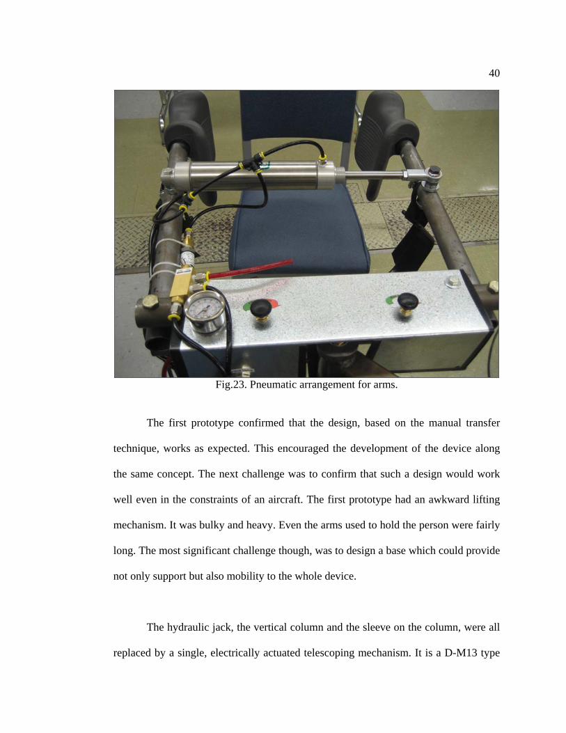
The lateral force can also be changed independently of the person’s weight.
This is done by using a pneumatic cylinder instead of the nylon straps in another
variation of the arm design. This arrangement can be seen in Fig.23. A single-acting
pneumatic cylinder is connected between the 2 arms. This cylinder is normally closed,
and opens when subjected to pneumatic pressure. The circuit is controlled by
including devices such as flow control valves and pressure regulators.
40
Fig.23. Pneumatic arrangement for arms.
The first prototype confirmed that the design, based on the manual transfer
technique, works as expected. This encouraged the development of the device along
the same concept. The next challenge was to confirm that such a design would work
well even in the constraints of an aircraft. The first prototype had an awkward lifting
mechanism. It was bulky and heavy. Even the arms used to hold the person were fairly
long. The most significant challenge though, was to design a base which could provide
not only support but also mobility to the whole device.
The hydraulic jack, the vertical column and the sleeve on the column, were all
replaced by a single, electrically actuated telescoping mechanism. It is a D-M13 type
41
telescoping column from X2 Technology in Sweden. The ability of this column to lift
a load of 300 lbs. at an offset of 40 inches makes it an appropriate match for our
needs. It runs on 24 Volts DC and has a variable speed control to adjust vertical
motion. This column is a more compact, aesthetically pleasing, easy-to-operate and
light in weight solution to the special requirements for functioning in an aircraft. The
length of the arms was reduced by 4 inches to 14 inches instead of the previous 18
inches.
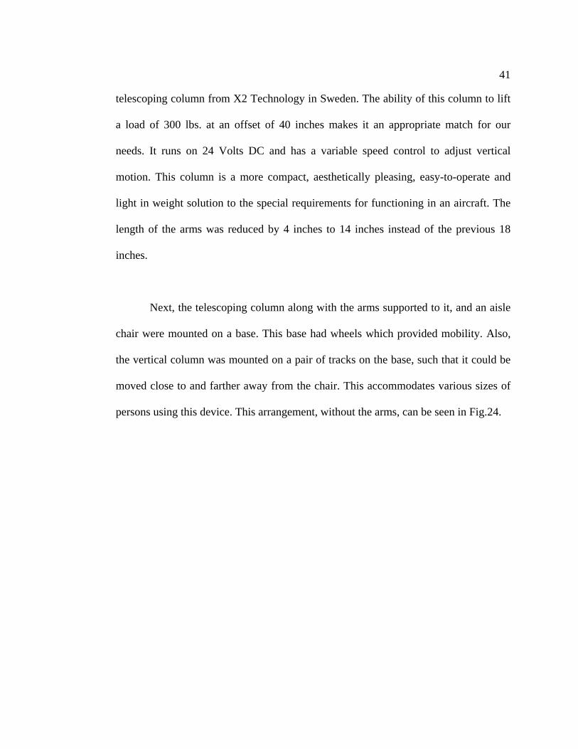
Next, the telescoping column along with the arms supported to it, and an aisle
chair were mounted on a base. This base had wheels which provided mobility. Also,
the vertical column was mounted on a pair of tracks on the base, such that it could be
moved close to and farther away from the chair. This accommodates various sizes of
persons using this device. This arrangement, without the arms, can be seen in Fig.24.

42
Fig.24. Second Prototype of the Transfer Device.
The integration of the chair and the vertical through a common base makes it
even simpler to perform a transfer. Instead of moving the person on a chair and the
transfer mechanism separately, it can be done together. This also assists in placing the
lifting mechanism relative to the person in the chair and the intended transfer seat in
the aircraft. In simple terms, the transfer procedure is as follows. At the end of the
jetbridge an attendant will operate the transfer device to transfer the passenger from
his/her wheelchair to the seat in the transfer device. The transfer device will then be
rolled into the aircraft on the wheels mounted on the base. The device will be placed
such that the chair is in line with the intended transfer seat. An attendant will then
operate the transfer device to move the passenger to the aircraft seat.
43
The mechanism of the arms is still to be added to the second prototype. It will
include either the pneumatic setup or the arrangement of the straps to hold a person.
The nylon straps do not require any external energy, but rely on the persons weight
transmitted through the legs. The pneumatic arrangement requires an external supply
of compressed air but accommodates passengers with disabilities caused by lost legs.
The design of the articulating arms which help maneuver and position the passenger
during the transfer requires analysis of the geometric constraints existing in an aircraft.
The number of links used and the length of each link are the factors that govern the
functionality of the mechanism.
2.3 Project Objectives
The space constraints presented by the interiors of an aircraft, and the
significance of weight of the device, are the major concerns in designing equipment to
be used in aircraft. The weight is a significant factor if the device is to be used for in-
flight applications such as for lavatory use. Weight can be reduced by using materials
like carbon fiber which are light in weight and have high strength. Weight can also be
reduced by reducing the volume of material used, that is, a smaller device will have
lesser weight compared to a bigger device of the same material. Thus, a small device
not only satisfies the space constraints but it also helps reduce the overall weight of the
device. On the other hand, a smaller device can reduce functionality. Thus, the device
has upper limit constraints imposed by the interiors of the aircraft and lower limit
constraints imposed by its functionality.

44
The complex 3 dimensional designs and arrangement of an aircraft’s interiors
make it difficult to envision its interaction with the transfer device with a person in it.
This challenge prompted the development of the first 2 prototypes. The prototypes
allowed us to investigate the physical interaction between the device and its
environment, the interior of an aircraft. But, the interior of an aircraft is limited to 2
rows of seats. Key elements such as the overhead bins were missing. Also, because of
the limited number of seats, it was not possible to create an aisle having seats on both
sides. Also, creating physical prototypes is expensive and time consuming. It slows
down the entire design process because of the time required to manufacture and test
the prototypes manually.
This encouraged the use of the latest developments in the field of Computer
Aided Design and Kinematic Simulation. The aim of the project is to find the best
design by investigating the interaction of the different designs of the transfer device
with the interiors of an aircraft using 3D Modeling and Kinematic Simulation
techniques.

45
3. MATERIALS AND METHODS
3.1 CATIA
CATIA (Computer Aided Three dimensional Interactive Application) is a
multi-platform PLM/CAD/CAM/CAE commercial software suite developed by
Dassault Systemes and marketed world-wide by IBM. Commonly referred to as 3D
Product Lifecycle Management software suite, CATIA supports multiple stages of
product development (CAx). The stages range from conceptualization, through design
(CAD), analysis (CAE), until manufacturing (CAM). CATIA provides open
development architecture through the use of interfaces, which can be used to
customize or develop applications.
The 2005 CATIA V5 release 16 was used in this study. The capabilities of this
version allows CATIA V5 to be applied in a wide variety of industries, such as
aerospace, automotive, industrial machinery, electrical, electronics, shipbuilding, plant
design, and consumer goods, including design for such diverse products as jewelry
and clothing. The Boeing Company used CATIA V3 to develop its 777 airliner, and is
currently using CATIA V5 for the 787 series aircraft. They have employed the full
range of Dassault Systemes' 3D PLM products, comprised of CATIA, DELMIA, and
ENOVIA, supplemented by Boeing developed applications (Boeing: 777 family).
46
CATIA V5 supports the following disciplines:
Mechanical Design:
The CATIA Mechanical Design discipline helps accelerate core activities of
development from concept to detailed design and sheet creation. Dedicated
applications for sheet metal and mold design enhance productivity and strongly reduce
time-to-market (CATIA V5: Mechanical Design).
Shape Design and Styling:
The CATIA Shape Design and Styling discipline allows design of innovative
products by creating, controlling and modifying engineered and free form surfaces
(CATIA V5: Shape Design and Styling).
Product Synthesis:
The extensive range of tools provided by the CATIA Product Synthesis
discipline allows automation and validation of the design and manufacturing data
(CATIA V5: Product Synthesis).
Equipment and Systems Engineering:
The CATIA Equipment and Systems Engineering discipline enables not only
design, but also integration of electrical, fluid and mechanical systems within a 3
dimensional mock-up (CATIA V5: Equipment and Systems Engineering).

47
Analysis:
The CATIA Analysis discipline provides fast design and analysis iterations
and allows easy product optimization based on product analysis specifications and
results (CATIA V5: Analysis).
Machining:
The CATIA NC Manufacturing discipline is a 3D PLM knowledge-based
product portfolio based on an infrastructure that covers all the specialized CAM
applications (CATIA V5: Machining).
Infrastructure:
The CATIA Infrastructure discipline provides a uniquely scalable and open
platform for collaborative product development (CATIA V5: Infrastructure).
Human Builder:
The Human Builder creates and manipulates accurate standard digital humans
in the digital mock-up environment for early human-product interaction analysis
(CATIA V5: Human Builder). Mannequin generation, gender and percentile
specification, mannequin manipulation techniques, animation generation, and
advanced vision simulation are a few of the tools available. The software allows non
human factors specialists to conduct simple human factors studies. In this study, we
used this discipline to create a mannequin and then incorporate it in the virtual
simulation environment.

48
3.2 Modeling Data:
For the purpose of investigating the performance of the transfer device in the
aircraft, it was important to model the environment accurately. The environment
consisted of appropriately arranged aircraft seats, the aircraft body, and a manikin to
replicate the transfer process.
3.2.1 Seats
The NCAT laboratory has airplane seats provided by Boeing. The various
dimensions of these seats were measured and used to make a 3D model in CATIA. 3
of these seats connected together form a typical row of seats as seen in Fig.25. The
seats when arranged correctly, form the most important part of the virtual
environment. The manikin will be transferred from a position in the aisle to the aisle-
seat in the row of seats.
Fig.25. Aircraft Seats

49
3.2.2. Aircraft body
The dimensions of the aircraft body are that of a Boeing 737 and were obtained
from a drawing available on Boeing’s website. A small section of the body, enough to
occupy 3 rows of seats was used in this study (Fig.26). The body was useful in
investigating the distance of the manikin from the overhead baggage bins during a
transfer.
Fig.26. Aircraft Body
50
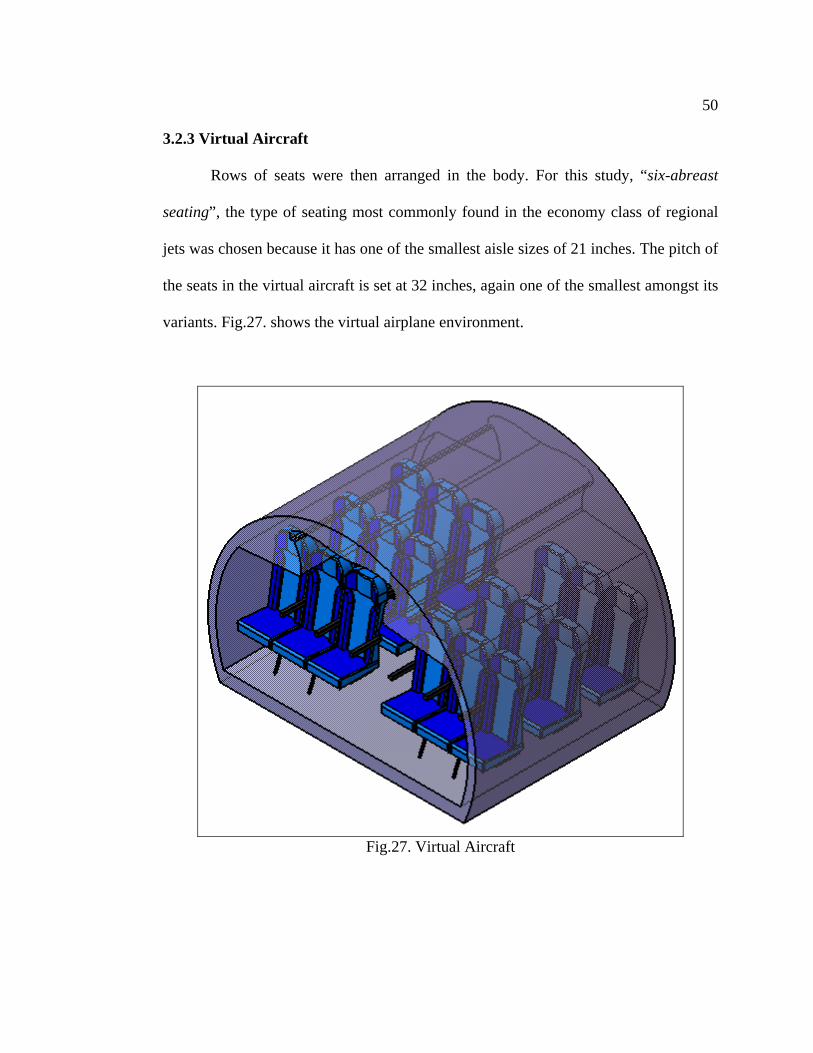
3.2.3 Virtual Aircraft
Rows of seats were then arranged in the body. For this study, “six-abreast
seating”, the type of seating most commonly found in the economy class of regional
jets was chosen because it has one of the smallest aisle sizes of 21 inches. The pitch of
the seats in the virtual aircraft is set at 32 inches, again one of the smallest amongst its
variants. Fig.27. shows the virtual airplane environment.
Fig.27. Virtual Aircraft

51
3.2.4 Tony the Passenger:
Tony, the virtual manikin, is a 90th percentile American male and was created
using the Human Builder module in CATIA. The module allows easy creation and
manipulation of the manikin. Tony, when created, is in the standing position (Fig. 28)
and is then made to be in a sitting position for the purpose of this study. Tony is
attached to the arms of the transfer device similar to a person being held from the sides
of the chest. Tony will be transferred by the device from a position in the aisle to the
aisle-seat in one of the rows of seats in the virtual airplane. Tony will help investigate
the clearance between an actual person and the seats and overhead baggage bins
during a transfer.
Fig.28. Tony the Passenger

52
3.2.5 Path-of-Transfer
The path-of-transfer is the path along which the passenger is moved during a
transfer from the aisle chair to the aircraft seat. The path used in this investigation was
2-dimensional and placed perpendicular to the axis of the aisle. The path was made of
3 sections as seen in Fig.29. The first section was vertical and accounted for the
passenger being lifted up from the chair such that the arm rest would not obstruct the
transfer. The second section was horizontal and represented the motion from the center
of the aisle to the center of the seat. The third section was vertical again, and
corresponded to the passenger being lowered to the aircraft seat.
Fig.29. Path-of-Transfer

53
3.3 Kinematic Model
A Kinematic model was created to simulate the movements of the physical
prototype. The components of the prototype have a definite relationship with each
other. Replicating these relationships makes it possible to reproduce the movements of
the prototype. The Kinematic model can be analyzed as discussed below.
Joint 1: Prismatic Joint – 2 links of the vertical column
The electrically actuated telescoping mechanism used to lift up the passenger,
consists of 2 square links. The telescoping mechanism is replicated by creating a
Prismatic joint between the 2 links and has a range of 26”.
Fig.30. Prismatic Joint in Kinematic Model
54
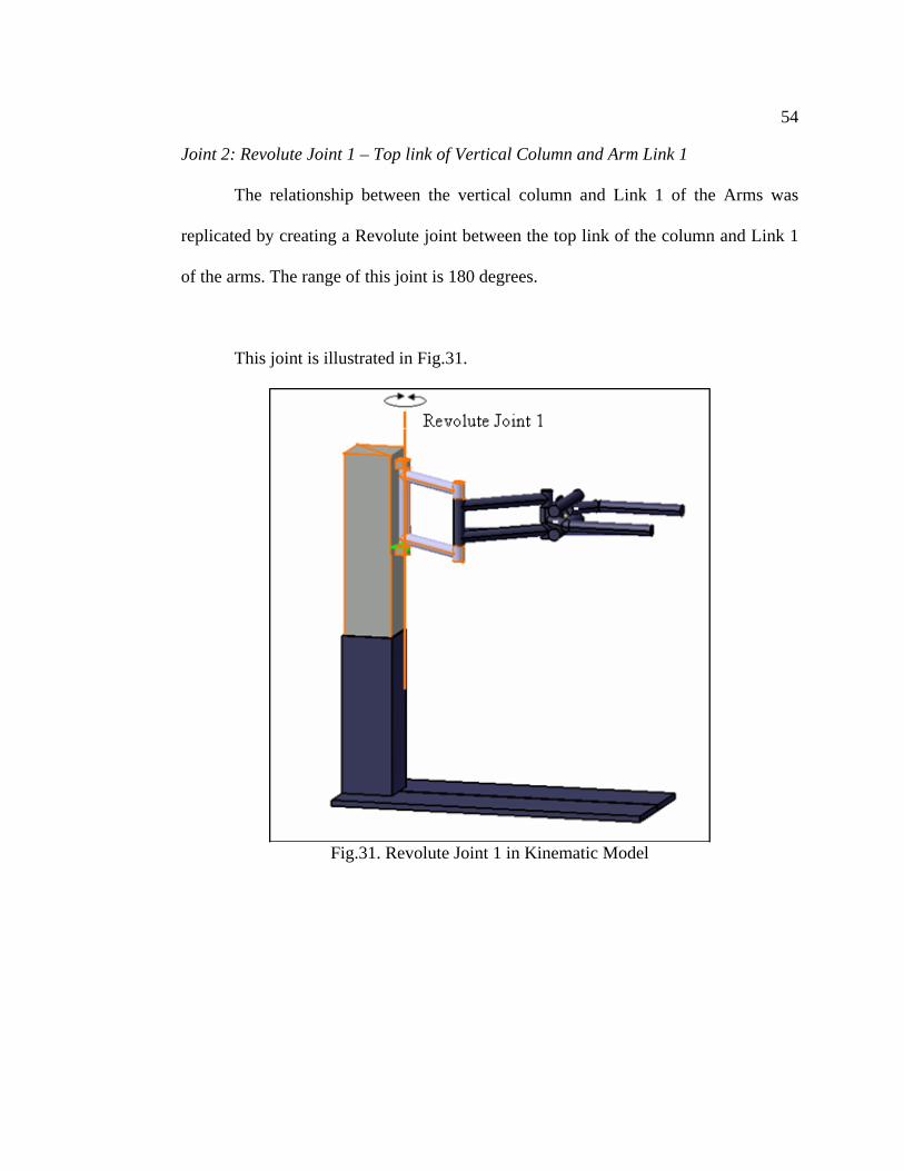
Joint 2: Revolute Joint 1 – Top link of Vertical Column and Arm Link 1
The relationship between the vertical column and Link 1 of the Arms was
replicated by creating a Revolute joint between the top link of the column and Link 1
of the arms. The range of this joint is 180 degrees.
This joint is illustrated in Fig.31.
Fig.31. Revolute Joint 1 in Kinematic Model

55
Joint 3: Revolute Joint 2 – Arm Link 1 and Arm Link 2.
The relationship between Link 1 and Link 2 of the Arms was replicated by
creating a Revolute joint between them. The range of this joint is 360 degrees.
This joint is illustrated in Fig.32.
Fig.32. Revolute Joint 2 of Kinematic model

56
Joint 4: Revolute Joint 3 –Arm Link 2 and Cross-Arm of Paddles.
The relationship between Link 2 of the Arms and the Cross-Arm of the Paddles
was replicated by creating a Revolute joint between them. The range of this joint is
360 degrees.
This joint is illustrated in Fig.33.
Fig.33. Revolute Joint 3 of Kinematic Model
The prismatic and 3 revolute joints together form the Kinematic Model. This
model accurately reproduces the movements of the physical prototype and its
simulation allows easy control and analysis of its performance.

57
3.4 Experimental Procedure
The experimental procedure was standardized across the various design
iterations to ensure accurate and consistent results. The 3 components of the transfer
device that were tested are the paddles, arms and the base-supports. Fig.34 shows
these and other components of the transfer device. The procedures used to investigate
the designs are discussed further.
Fig.34. Components of the Transfer Device.
58
3.4.1 Paddles.
Design Requirements:
The best design of the Paddles will –
1. Satisfactorily complete the transfer from the initial to the final position.
2. Not generate any interference between the critical components.
3. Utilize the smallest lengths for the Paddles.
Constraints:
1. The space available between the seats of an aircraft creates a constraint on the
maximum length of the paddles.
2. The paddles are the only components of the device which come in contact with
the passenger. If the length is too small, there is a possibility of the cross-arm
of the paddles hurting the passengers’ chest. This introduces a constraint on the
minimum length of the paddles.
3. The requirement of a good moment-arm for the strap mechanism to work
effectively generates a constraint on the minimum length of the paddles.
Materials Used:
Arms with both Link 1 and Link 2 being 12” long, vertical column, Base, Virtual
aircraft, Tony, Path-of-Transfer.

59
Procedure:
1. Starting Position: Tony was seated in the aisle chair (not shown) with the
Paddles positioned on the sides of his chest. The Arms were positioned such
that the Vertical Column did not interfere with Tony’s knees.
2. Transfer: Tony was then transferred from the aisle chair to the aircraft seat. It
was made sure that there was no interference between Tony and the front seat,
and the device and the front seat.
3. Final Position: Tony was seated in the center of the aisle seat of the aircraft.
This ensured that Tony would not have to be pushed any further after the
transfer by the device was completed.
4. Data recorded: The following data was recorded during the transfer:
a. Interference-check between Tony and front seats.
b. Interference-check between Tony and overhead bins.
c. Interference-check between arms of device and front seats.
Fig.35. CATIA Reporting Interference

60
In CATIA, interference between components is shown by highlighting the
interfering components. The picture on the previous page shows that the seat is
interfering with link 2 of the arms on device.
Fig.36. Sequence of transfer form aisle chair to aircraft seat.
61
3.4.2 Arms
Design Requirements:
The best design of the Arms will-
1. Satisfactorily complete the transfer from the initial to the final positioning
2. Not generate any interference between the critical components
3. Have an adequate range of operation
Constraints:
1. The space available within the aisle and the arrangement of the seats in an
aircraft creates a constraint on the maximum length of the links.
2. The requirement of satisfactorily completing the transfer introduces a
constraint on the minimum length of the links.
Materials Used:
Bent-Paddles, vertical column, Base, Virtual aircraft, Tony, Path-of-Transfer.
Procedure:
A design requirement for the Arms was to have an adequate range of operation. This
would make the device robust from the users’ point of view. To get the range of
operation, the procedure was repeated at least at 2 positions, and more if required,
along the aisle of the aircraft. It was ensured that the device satisfies the design
requirements at both the aisle-positions. The procedure followed at the aisle-positions
was as follows -

62
1. Starting Position: Tony was seated in the aisle chair (not shown) with the
Paddles positioned on the sides of his chest. The Arms were positioned such
that the Vertical Column did not interfere with Tony’s knees.
2. Transfer: Tony was then transferred from the aisle chair to the aircraft seat. It
was made sure that there was no interference between Tony and the front seat,
and the device and the front seat.
3. Final Position: Tony was seated in the center of the aisle seat of the aircraft.
This ensured that Tony would not have to be pushed any further after the
transfer by the device was completed.
4. Data recorded: The following data was recorded during the transfer:
a. Interference-check between Tony and front seats.
b. Distance between Tony and front seats.
c. Interference-check between Tony and overhead bins.
d. Distance between Tony and overhead bins.
e. Interference-check between Arms of device and front seats.
f. Position of base along the aisle of the aircraft.
5. The range of operation was calculated using the position of the base recorded
in both the aisle-positions.

63
3.4.3 Base-Supports
Design Requirements:
The best design of the Base-Supports will-
1. Not obstruct the motion of the device in the aisle of the aircraft when it is
moved in and out of the aircraft.
2. Not generate any interference between the critical components during its
operation.
3. Have a large range of operation
4. The supports may allow transfer of passenger towards any 1, or both directions
from the aisle to the seat.
Constraints:
1. The space available within the aisle and the arrangement of the seats in an
aircraft creates a constraint on the maximum length of the links.
2. The ability to support the device during a transfer generates a constraint on the
minimum length of the supports. This minimum length was considered to be
20”, the distance from the center of the aisle to the center of the seat, also the
maximum overhang generated during the transfer.
Materials Used:
Vertical column, Base, Virtual aircraft.

64
Procedure:
One of the design requirements for the Base-Supports was to have a large range of
operation. This would make the device robust from the users’ point of view. To get the
range of operation, the procedure was repeated at least at 2 positions, and more if
required, along the aisle of the aircraft. It was ensured that the device satisfies the
design requirements at both the aisle-positions. The procedure followed at the aisle-
positions was as follows -
1. The base, with the supports, was appropriately positioned in the aisle and the
supports-mechanism was activated.
2. The supports were extended and retracted and the operation was checked for
interference.
3. Data recorded: The following data was recorded during the transfer:
a. Interference-check between supports and seats
b. Position of the base along the aisle of the aircraft.
4. The range of operation was calculated using the position of the base recorded
in both the aisle-positions.
65
4. RESULTS
This section presents the results of the performance of the various designs
tested for the paddles, arms and base-supports. 3 designs for the paddles, 6 designs for
the arms and 4 designs for the base-supports were tested.
4.1 Paddles
3 design variations were tested for the Paddles. The designs and their results
are discussed further.
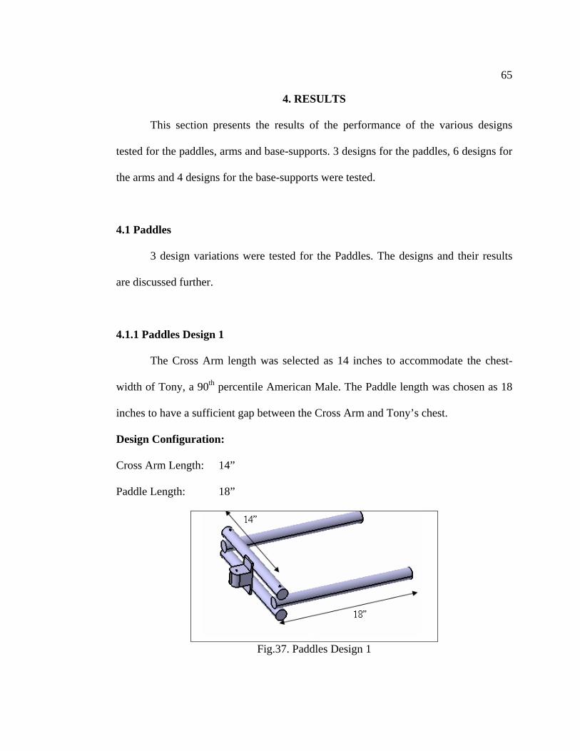
4.1.1 Paddles Design 1
The Cross Arm length was selected as 14 inches to accommodate the chest-
width of Tony, a 90th percentile American Male. The Paddle length was chosen as 18
inches to have a sufficient gap between the Cross Arm and Tony’s chest.
Design Configuration:
Cross Arm Length: 14”
Paddle Length: 18”
Fig.37. Paddles Design 1

66
Results:
a. Interference-check between Tony and front seats: No Interference
b. Interference-check between Tony and overhead bins: No Interference
c. Interference-check between arms of device and front seats: Interference
4.1.2 Paddles Design 2
During the investigation of the Design 1, it was noticed that the length of the
paddles caused interference between the paddles and the aircraft seat. To avoid this,
the length was reduced to 14 inches. This length also generated a sufficient gap
between the Cross Arm and Tony’s chest.
Design Configuration:
Cross Arm Length: 14”
Paddle Length: 14”
Fig.38. Paddles Design 2
Results:
a. Interference-check between Tony and front seats: No Interference

67
b. Interference-check between Tony and overhead bins: No Interference
c. Interference-check between arms of device and front seats: No Interference
4.1.3 Paddles Design 3
The investigation of design 2 revealed no interference. The gap created
between the Cross Arm and Tony’s chest was also sufficient. For Design 3, the
corners generated at the Paddle-Cross Arm joints were eliminated.
Design Configuration:
Cross Arm Length: 10”
Paddle Length: 14” (Bent Design)
Fig.39. Paddles Design 3
Results:
a. Interference-check between Tony and front seats: No Interference
b. Interference-check between Tony and overhead bins: No Interference
c. Interference-check between arms of device and front seats: No Interference
68
4.2 Arms
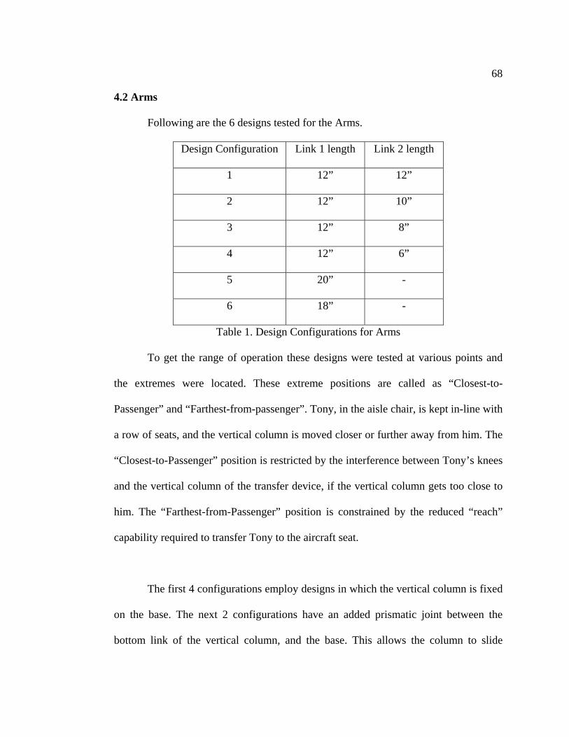
Following are the 6 designs tested for the Arms.
Design Configuration Link 1 length Link 2 length
1 12” 12”
2 12” 10”
3 12” 8”
4 12” 6”
5 20” -
6 18” -
Table 1. Design Configurations for Arms
To get the range of operation these designs were tested at various points and
the extremes were located. These extreme positions are called as “Closest-to-
Passenger” and “Farthest-from-passenger”. Tony, in the aisle chair, is kept in-line with
a row of seats, and the vertical column is moved closer or further away from him. The
“Closest-to-Passenger” position is restricted by the interference between Tony’s knees
and the vertical column of the transfer device, if the vertical column gets too close to
him. The “Farthest-from-Passenger” position is constrained by the reduced “reach”
capability required to transfer Tony to the aircraft seat.
The first 4 configurations employ designs in which the vertical column is fixed
on the base. The next 2 configurations have an added prismatic joint between the
bottom link of the vertical column, and the base. This allows the column to slide

69
relative to the base. This joint was added as an attempt to maintain the reach of the
device after the Arms were reduced to one link.
4.2.1 Arms Design 1
The prototype made at NCAT had 3 links which were 12”, 6” and 6” in length,
adding up to 24”. Since that configuration worked well, a device with 2 links was
investigated. The total length of the links was maintained at 24”.
This design is illustrated in Fig.40.
Design Configuration:
Link 1: 12”
Link 2: 12”
Fig.40. Arms Design 1
70
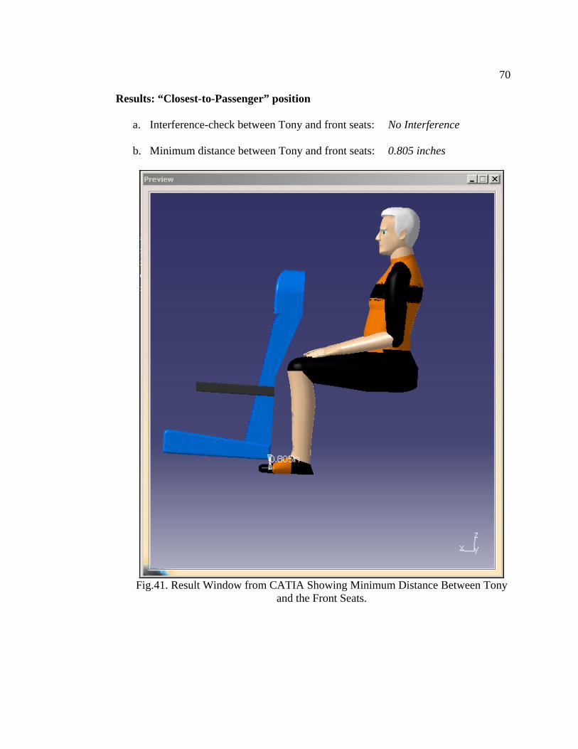
Results: “Closest-to-Passenger” position
a. Interference-check between Tony and front seats: No Interference
b. Minimum distance between Tony and front seats: 0.805 inches
Fig.41. Result Window from CATIA Showing Minimum Distance Between Tony
and the Front Seats.

71
c. Interference-check between Tony and overhead bins: No Interference
d. Minimum distance between Tony and overhead bins: 1.4 inches
Fig.42. Result Window from CATIA Showing Minimum Distance Between Tony
and Overhead Bins.

72
e. Interference-check between Arms of device and front seats: No Interference
f. Position of base along the aisle of the aircraft: 11.998 inches from front seat
Fig.43. Distance of Base from Front Face of Front Seat.
The result windows shown for Design 1 were recorded for all the designs. For
the remaining design configurations for the Arms, only the numerical values are
shown.

73
Results: “Farthest-from-Passenger” position
a. Interference-check between Tony and front seats: No Interference
c. Minimum distance between Tony and front seats: 0.779 inches
b. Interference-check between Tony and overhead bins: No Interference
c. Minimum distance between Tony and overhead bins: 1.141 inches
d. Interference-check between Arms of device and front seats: No Interference
e. Position of base along the aisle of the aircraft: 3.756 inches from front seat
The range of operation for this configuration is 11.998 – 3.756 = 8.242 inches.

74
4.2.2 Arms Design 2
Design Configuration:
Link 1: 10”
Link 2: 12”
Results: “Closest-to-Passenger” position
a. Interference-check between Tony and front seats: No Interference
b. Minimum distance between Tony and front seats: 0.795 inches
c. Interference-check between Tony and overhead bins: No Interference
d. Minimum distance between Tony and overhead bins: 2.076 inches
e. Interference-check between Arms of device and front seats: No Interference
f. Position of base along the aisle of the aircraft: 13.11 inches from front seat
Results: “Farthest-from-Passenger” position
a. Interference-check between Tony and front seats: No Interference
b. Minimum distance between Tony and front seats: 0.778 inches
c. Interference-check between Tony and overhead bins: No Interference
d. Minimum distance between Tony and overhead bins: 1.22 inches
e. Interference-check between Arms of device and front seats: No Interference
f. Position of base along the aisle of the aircraft: 6.476 inches from front seat
The range of operation for this configuration is 13.11 – 6.476 = 6.634 inches.

75
4.2.3 Arms Design 3
Design Configuration:
Link 1: 8”
Link 2: 12”
Results: “Closest-to-Passenger” position
a. Interference-check between Tony and front seats: No Interference
b. Minimum distance between Tony and front seats: 0.776 inches
c. Interference-check between Tony and overhead bins: No Interference
d. Minimum distance between Tony and overhead bins: 1.999 inches
e. Interference-check between Arms of device and front seats: No Interference
f. Position of base along the aisle of the aircraft: 13.197 inches from front seat
Results: “Farthest-from-Passenger” position
a. Interference-check between Tony and front seats: No Interference
b. Minimum distance between Tony and front seats: 0.78 inches
c. Interference-check between Tony and overhead bins: No Interference
d. Minimum distance between Tony and overhead bins: 1.183 inches
e. Interference-check between Arms of device and front seats: No Interference
f. Position of base along the aisle of the aircraft: 8.343 inches from front seat
The range of this configuration is 13.197 – 8.343 = 4.854 inches.
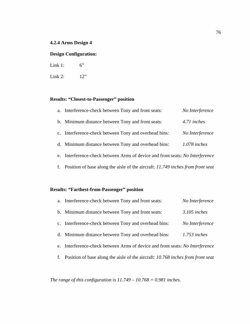
76
4.2.4 Arms Design 4
Design Configuration:
Link 1: 6”
Link 2: 12”
Results: “Closest-to-Passenger” position
a. Interference-check between Tony and front seats: No Interference
b. Minimum distance between Tony and front seats: 4.71 inches
c. Interference-check between Tony and overhead bins: No Interference
d. Minimum distance between Tony and overhead bins: 1.078 inches
e. Interference-check between Arms of device and front seats: No Interference
f. Position of base along the aisle of the aircraft: 11.749 inches from front seat
Results: “Farthest-from-Passenger” position
a. Interference-check between Tony and front seats: No Interference
b. Minimum distance between Tony and front seats: 3.105 inches
c. Interference-check between Tony and overhead bins: No Interference
d. Minimum distance between Tony and overhead bins: 1.753 inches
e. Interference-check between Arms of device and front seats: No Interference
f. Position of base along the aisle of the aircraft: 10.768 inches from front seat
The range of this configuration is 11.749 – 10.768 = 0.981 inches.
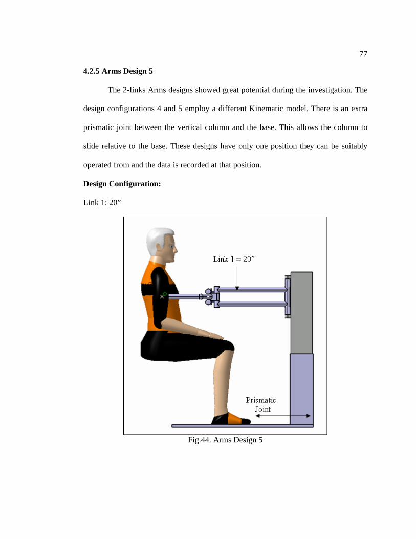
77
4.2.5 Arms Design 5
The 2-links Arms designs showed great potential during the investigation. The
design configurations 4 and 5 employ a different Kinematic model. There is an extra
prismatic joint between the vertical column and the base. This allows the column to
slide relative to the base. These designs have only one position they can be suitably
operated from and the data is recorded at that position.
Design Configuration:
Link 1: 20”
Fig.44. Arms Design 5

78
Results:
a. Interference-check between Tony and front seats: No Interference
b. Minimum distance between Tony and front seats: 2.634 inches
c. Interference-check between Tony and overhead bins: No Interference
d. Minimum distance between Tony and overhead bins: 1.173 inches
e. Interference-check between Arms of device and front seats: No Interference
4.2.6 Arms Design 6 Design Configuration: Link 1 = 18” Results:
a. Interference-check between Tony and front seats: No Interference
b. Minimum distance between Tony and front seats: 0.779 inches
c. Interference-check between Tony and overhead bins: No Interference
d. Minimum distance between Tony and overhead bins: 1.26 inches
e. Interference-check between Arms of device and front seats: No Interference

79
4.3 Base-Supports
4 designs were tested for the Base-Supports. Unlike the Paddles and Arms,
these designs are not derived from each other. These designs were tested at various
points along the aisle and the range of operation was calculated by using the positions
at which the operation was successfully carried out without generating any
interference. During a transfer, when the passenger is moved towards the aircraft seat,
a moment is generated which tends to tip the device on its sides. The function of the
base-supports is to support the device during the transfer and prevent it from tipping
over.
Nomenclature:
Fig.45. Nomenclature for the Seats

80
4.3.1 4-Bar Mechanism
This mechanism utilizes the base as one of the links along with the leg which
extends out. The leg is retracted in the initial position and extended out between the
seats in the final position. Fig.46. illustrates the mechanism in top view and represents
the retracted position. The design configuration and its results are discussed below.
Design Configuration:
Link 1: Fixed Link: Base
Link 2: Crank
Link 3: Rocker: Leg
Link 4: Slider
Fig.46. 4-Bar Mechanism for Supports
Fig.47. 4-Bar Mechanism in Extended position

81
Results:
This design required a wide space to swing-open. The range of operation was 2
inches.
4.3.2 Wing Mechanism
This mechanism has 2 links which appear like wings when they open during
operation. In the retracted position, these links fold up along the vertical column and
in the extended position, spread out under the seats. Fig.48.shows the basic
dimensions of the Wing Mechanism and Fig.49.illustrates the mechanism’s operating
and extended positions.
Fig.48. Basic dimensions of the Wing mechanism

82
Fig.49. Wing mechanism in operating and extended positions
Results:
This mechanism operated between the back leg of the front seat and the front
face of the back seat. This space is 6 inches wide and the supports are 2 inches wide.
Thus, the range of operation was 4 inches.
4.3.3 Horizontal-Wing Mechanism
This design was derived from the previous wing design. It uses a similar wing-
mechanism which operated in the horizontal instead of vertical plane. Fig.50.shows
the basic dimensions of the Horizontal Wing Mechanism and Fig.51. illustrates the
mechanism’s operating and extended positions.
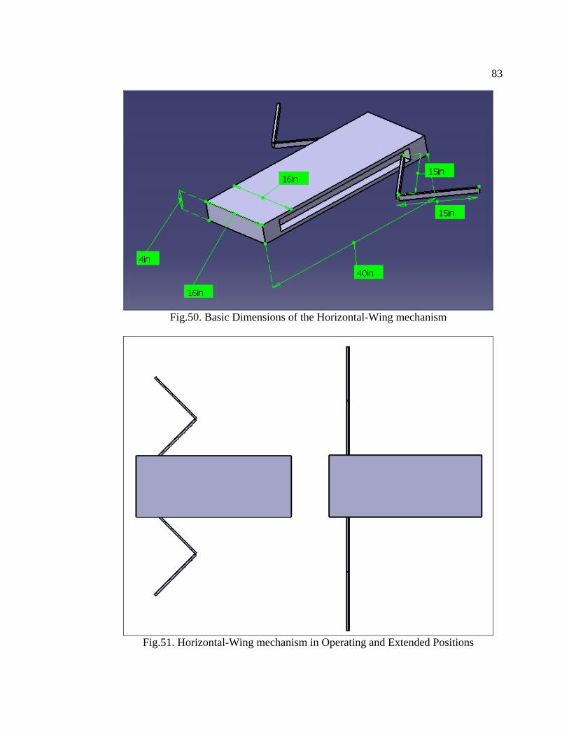
83
Fig.50. Basic Dimensions of the Horizontal-Wing mechanism
Fig.51. Horizontal-Wing mechanism in Operating and Extended Positions

84
Results:
This mechanism operated between the back legs of the front seat and the front
legs of the back seat. This space was 8 inches wide and the range of operation for this
device was 5.7 inches.
4.3.4 Telescoping Mechanism
This design used a telescoping mechanism which extended out between the
seats. The telescoping mechanism consists of 2 links which extend out when required.
In the retracted position, these links are stowed in the base itself. Fig.52. shows the
basic dimensions of the Horizontal Wing Mechanism and Fig.53. illustrates the
mechanism’s retracted and extended positions.
Fig.52. Basic Dimensions of the Telescoping mechanism

85
Fig.53. Telescoping Mechanism in Retracted and Extended Positions
Results:
This mechanism operated between the back legs of the front seat and the front
legs of the back seat. This space is 8 inches wide and the supports are 2 inches wide.
Thus, the range of operation is 6 inches.

86
5. DISCUSSION
This section evaluates the performance of the results presented in the previous
section. After considering the various design options available, the best for the
paddles, arms and base-supports are identified.
5.1 Paddles
The design requirements for the paddles called for the smallest paddles which
could satisfactorily complete the transfer. Constraints that affected the design included
those produced by the space available in the aircraft, the interference between the
paddles and the passenger and the moment-arm required to operate the strap
mechanism.
Design 1
Design 1 was the design of the paddles used on the prototype at NCAT. The
prototype made at NCAT utilizes paddles which are 18” in length. The cross-arm is
14” in length, the chest-width of Tony. The results show that Design 1 generated
interference between the paddles and the aircraft seats. It was observed that the length
of the paddles was causing this interference. Hence, this length was reduced and
Design 2 was created.
Design 2
Design 2 utilized a length of 14” for the paddles. The cross-arm specifications
were not changed. This design worked well and no interference was produced. Also,

87
these paddles generate a sufficient gap between the cross-arm and Tony’s chest, and a
functional moment-arm. Although this design satisfied all the requirements and the
length of the paddles could no longer be reduced, a third design was created.
Design 3
Design 3 eliminated the corner by the paddles and cross-arm. It was observed
that this design produced a greater clearance between the paddles and seats during a
transfer.
Best Design
Design 3 was thus the best design amongst the three and is recommended for
use in the final design of the transfer device. This design will also be used in all
further analysis in this project.
5.2 Arms
The design requirements for the arms called for a design with a sufficiently
large range of operation which could satisfactorily complete a transfer. Constraints
that affected the design included those produced by the space available in an aircraft,
the interference between the arms and the aircraft seats and the “reach” required for
completing the transfer.
Design 1
The prototype at NCAT utilizes a design with 3 links. Since this design worked
well in the lab, it was decided to test a smaller design. Thus, design 1 had 2 links

88
instead of 3. Results show that this design worked very well with a large range of
operation of 8.2”.
Design 2
Since design 1 worked well, design 2 was generated by reducing the length of
link 1. The length of link 1 was reduced to 10” and that of link 2 was maintained at
12”. Link 2 was kept at 12” to aid the ability to “reach” up to the center of the aisle
seat. Investigating the effects of changing link 2 instead of 1, or both, is a
recommendation for future research. It can be seen from the results that design 2
performed well too and had a range of operation of 6.6”.
Design 3
As design 2 performed suitably, the length of link1 was further reduced to 8”.
Thus, design 3 had link with a length of 8” and link 2 was again maintained at 12”.
This design also satisfactorily performed the transfer without generating any
interference. The range of operation dropped down to 4.8”.
Design 4
Once again, the length of link 2 was reduced by 2”. Design 4, thus, had link 1
with a length of 6” and link 2 with a length of 12”. The investigation showed that
even though the transfer was performed satisfactorily, the range of operation declined
to a little less than 1”. Due to this drop in the range, no further alterations were made
to the 2-link design.

89
Design 5
Link 1 was eliminated and a 1-link design was introduced. To make up for the
lost reach, an extra joint was added to the Kinematic model. This joint, a prismatic one
between the vertical column and the base, allows the column to slide relative to the
base. This permits the column to move closer towards the passenger during the
transfer and as a result, increase the “reach” of the arms. Design 5 was thus created
using one link with a length of 20” and an extra prismatic joint. Investigation proved
that this design concept worked very well. The transfer was satisfactorily completed
without generating any interference. But, due to the inherent nature of the design of
having only one link, there is no range of operation for this design. The device has to
be positioned at a particular location along the aisle to complete the transfer.
Design 6
The performance of the previous design encouraged the generation of design 6.
This design had a link with a length of 18” instead of 20. Results show that this design
too, performed well without producing any interference. No further alterations were
made to this design because a length of 18” is essential to satisfactorily transfer the
person through the distance from the aisle to the seat, which is 20”.
Best Design
Designs 5 and 6 showed great potential in-spite using only one link. The factor
that comes into play, though, is the fact that this design requires simultaneous
movements of the arms and the vertical column. If these movements are not in-sync,

90
the transfer of the passenger will be hindered. It can also cause interference between
the critical components and collision between the passenger and aircraft seats.
The 2-link designs performed well without showing such problems. These designs
were simple to operate and easier to control. Designs 3 & 4 used a link 1 having
lengths of only 6” and 8”, and performed well. But these designs had a range of
operation which was less than 5”. Design 1, which used a length of 12” for link1 also
performed well and had a range of 8.2”. But design 2 which had a smaller link length
of 10” also had an adequate range of 6.6”. Hence, for having small links and an
adequate range of operation, Design 2 is judged as the best design for the arms.
5.3 Base-Supports
The design requirements for the base-supports asked for a design which
provided sufficient support for the transfer device without causing it any hindrance
during the transfer device’s passage through the aisle of an aircraft. A good design
also required a large range of operation. Constraints that influenced the design
included those generated by the space available in an aircraft and the ability to
sufficiently support the transfer device during a transfer.
Design 1: 4-Bar Mechanism
The 4-bar mechanism utilizes a swinging motion of the arm which requires a
large space. The legs of the aircraft seats obstructed the operation of this mechanism
causing the range of operation to be a mere 2”. The vertical column can be attached to
either end of the base.

91
Design 2: Wing Mechanism
The previous investigation showed that the modest space available on the floor
of an aircraft is not favorable to a design utilizing a horizontal-swing motion. Hence,
the wing mechanism looked at utilizing the available space in the vertical plane. The
results show that the wing mechanism performed better than the 4-bar mechanism and
had a range of operation of 4 inches. Also, the lengths of the supports were 30”, and
could be increased further without affecting the range of operation by a significant
amount.
Design 3: Horizontal Wing
The performance of the previous wing mechanism encouraged the
investigation of a similar design which operated in the horizontal plane. Unlike the 4-
bar mechanism which also operated in the horizontal plane, the horizontal wing
mechanism worked well in avoiding any interference with the seats. The results show
that this device had a range of operation of 5.7”, almost 2” more than the previous
wing mechanism. The vertical column can be attached to either end of the base.
Design 4: Telescoping Mechanism
The previous designs have shown that a mechanism with any kind of swinging
motion generates interference with the seats negatively affecting the range of
operation. The telescoping mechanism attempts to evade this problem by operating in
a straight line. The results show that it this idea was largely successful providing it
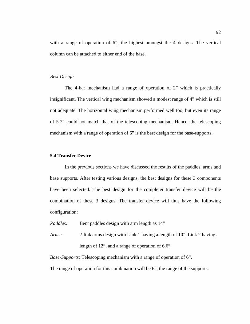
92
with a range of operation of 6”, the highest amongst the 4 designs. The vertical
column can be attached to either end of the base.
Best Design
The 4-bar mechanism had a range of operation of 2” which is practically
insignificant. The vertical wing mechanism showed a modest range of 4” which is still
not adequate. The horizontal wing mechanism performed well too, but even its range
of 5.7” could not match that of the telescoping mechanism. Hence, the telescoping
mechanism with a range of operation of 6” is the best design for the base-supports.
5.4 Transfer Device
In the previous sections we have discussed the results of the paddles, arms and
base supports. After testing various designs, the best designs for these 3 components
have been selected. The best design for the completer transfer device will be the
combination of these 3 designs. The transfer device will thus have the following
configuration:
Paddles: Bent paddles design with arm length as 14”
Arms: 2-link arms design with Link 1 having a length of 10”, Link 2 having a
length of 12”, and a range of operation of 6.6”.
Base-Supports: Telescoping mechanism with a range of operation of 6”.
The range of operation for this combination will be 6”, the range of the supports.

93
6. CONCLUSION
6.1 Limitations of this project
Though this project succeeded in achieving its purpose, it has a few limitations
which should be taken note of. First, the dimensional data used to model the aircraft
seats and body is not very accurate. These dimensions were measured off of existing
seats and limited data available through Boeing. Though this affects the numerical
values of the results, the performance of the designs relative to each other remains the
same. Also, for the purpose of establishing a procedure for testing performance, only a
modest number of designs were investigated. This project only demonstrates the
performance of the tested designs and does not necessarily conclude their superiority
to new ideas. Only a few aspects of the design were investigated in this project. The
length of the base and its ability to through turn through aisles in multi aisle aircrafts
was not considered in this project. The designs were investigated more from the
geometrical point of view and not the mechanical design and strength. Satisfactory
attention was given to not test designs which are not feasible to manufacture.
Limited simulation resources were utilized in this project. Only CATIA was
used for the simulations and its capabilities were not compared to other similar
resources available, if any. Tools such as “Band Analysis” can increase the validity of
the results by giving a detailed analysis of the distance between the components at
each point during a transfer.

94
6.2 Suggestions for Future Studies
The Virtual Environment used in this project which was comprised of the
aircraft seats and aircraft body can be dimensionally more accurate than this study.
These components affect the performance of all the designs and their accuracy is
necessary in predicting the effectiveness of the designs. The 3D models of these
components could be obtained directly from their manufacturers for best precision.
The Virtual Environment in this study was modeled after that of the Boeing
737 series aircrafts. Though this aircraft is one of the most common ones used for
domestic travel, it is not the smallest. Smaller aircraft have smaller aisles and also
smaller seat pitch in some cases. The designs can be tested in these environments too.
Multi-aisle aircrafts sometimes have aisles which have turns and bends. The
length of the base should be checked against the ability to satisfactorily move along
these turns and bends. Also, the need and advantages of testing more number of
designs is evident.

95
6.3 Suggestions for Future Designs
The mechanism for operating the paddles can be as simple as the nylon straps
arrangement or can employ a pneumatic cylinder. The operating mechanism affects
the length of the paddles and when its design is finalized, the design of the paddles can
be refined by carrying out an investigation of its performance in the Virtual
Environment.
In this project the design of the Arms was varied by changing the length of
Link 1 only. The length of Link 2 can also be changed and its effect can be
investigated. Only 4 designs were tested for the base-supports.
More designs can be tested and a finite element analysis can be done to verify
their ability to support the device during a transfer. The combination of the base and
supports should be able to move through turns and bends in aircraft aisles. Another
study can be conducted where these turns in aircraft aisles are included in the virtual
environment and the base with the supports is moved along the aisle to check for
maneuverability.
96
6.4 Overall Project Summary
The biomechanics study and the computer survey identify the need for the
development of an alternative for the manual transfer process which is an integral part
of air travel for a large population. The current practice is unsafe, uncomfortable, and
undignified. It is also a deterrent for people who want to travel and is thus harming the
air industry. With the predicted increase in number of wheelchair bound passengers in
the near future, developing an alternate solution is not only ethical, but also makes
good business sense.
The research at the National Center for Accessible Transportation has made
significant development towards this goal. The next prototype can utilize the results of
this project and a study conducted to investigate the effects of lateral force on
passenger comfort during a mechanically assisted dependant transfer. This prototype
will be another significant step towards the end product that NCAT is striving for.
This project investigated many design variations and outlined the best design
for each of the components of the transfer device. Another significant achievement of
this project was that is demonstrated the potential of 3D modeling and kinematic
simulation as a design aid in machine design. It established and showed the
application of a meticulous procedure for investigating the performance of the various
designs. The Virtual Environment created for this project can be used for future
studies. By creating similar environments and following a slightly modified procedure,
virtually any scenario can be investigated.

97
BIBLIOGRAPHY
United States Department of Justice. (1990). Americans with Disabilities Act of 1990. Retrieved June 30, 2007, from http://ada.gov/pubs/ada.htm Bureau of Transportation Statistics. (2003). BTS Issue Brief, Vol. 3, April 2003. Retrieved June 30, 2007, from http://ada.gov/pubs/ada.htm International Center for Accessible Transportation: Background. Retrieved June 30, 2007, from http://www.icat-ciat.org/whatisicat.html Harber, P., Billete, ., Gutowskmi, ., Soohook, ., Lew, M., Romana, ., & Horanm, . (1985). Occupational low-back in hospital nurses, Journal of Occupational Medicine. 27, 518-524. United States Department of Transportation. (1990). Air Carrier Access Act, 1990. Retrieved July 10, 2007, from http://www.dotcr.ost.dot.gov/documents/Acc/disabled.pdf Krishnamoorthy, C S., Rajeev, S., & Rajaraman, A. (2005). Computer Aided Design. Middlesex, Alpha Science International Ltd. Kelton, W David., Sadowski, Randall P., Sturrock, & David T. (2007). Simulation with Arena (4th Ed.). New York, McGraw-Hill. IBM Software: CATIA. Retrieved July 15, 2007, from http://www-306.ibm.com/software/applications/plm/catiav5/ Cust, G., Pearson, JCG., Mair, A. (1972). The Prevalence of low back pain in nurses, International Nursing Review 19:169-179. Safe Patient Handling and Movement. (2001). Retrieved July 15, 2007, from http://www.revelationsafety.com/CMSFiles/Ergo_Guide_Safe_Patient_Handling_(I).pdf Stubbs, D., Buckle, P., Hudson, M., & Rivers, P. (1983). Back pain in the nursing profession: The effectiveness of training, Ergonomics 26: 767-779. Garrett, B., Singiser, D., Banks, S M. (1992). Back injuries among nursing personnel: the relationship of personal characteristics, risk factors, and nursing practices, American Association of Occupational Health Nurses Journal 1992 Nov; 40(11):510-6. SureHands. Retrieved June 1, 2007, from http://208.56.109.158/mission_us.html
98
Haycomp Products: Eagle 2. Retrieved July 20, 2007, from http://www.haycomp.com.au/default.cfm?id=82 XP Equipment: XP Boarding Chair. Retrieved July 20, 2007, from http://www.xpiration.com/pages/boardingchair.html Boeing: 777 family. Retrieved July 25, 2007, from http://www.boeing.com/commercial/777family/pf/pf_computing.html CATIA V5: Mechanical Design. Retrieved July 26, 2007, from http://www-306.ibm.com/software/applications/plm/catiav5/disciplines/mechdsgn/ CATIA V5: Shape Design and Styling. Retrieved July 26, 2007, from http://www-306.ibm.com/software/applications/plm/catiav5/disciplines/shapedsgn/ CATIA V5: Product Synthesis. Retrieved July 26, 2007, from http://www-306.ibm.com/software/applications/plm/catiav5/disciplines/prodsynth/ CATIA V5: Equipment and Systems Engineering. Retrieved July 26, 2007, from http://www-306.ibm.com/software/applications/plm/catiav5/disciplines/esengin/ CATIA V5: Analysis. Retrieved July 26, 2007, from http://www-306.ibm.com/software/applications/plm/catiav5/disciplines/analysis/ CATIA V5: Machining. Retrieved July 26, 2007, from http://www-306.ibm.com/software/applications/plm/catiav5/disciplines/ncmanuf/ CATIA V5: Infrastructure. Retrieved July 26, 2007, from http://www-306.ibm.com/software/applications/plm/catiav5/disciplines/infrastructure/ CATIA V5: Human Builder. Retrieved July 26, 2007, from http://www-306.ibm.com/software/applications/plm/catiav5/prods/hbr/