Embed Size (px)
Citation preview
AN 26.19USB Battery Charging with the USB253x/USB46x4/
USB3x13 Hub Controllers
Authors: Arnaldo Cruz, Brigham Steele, and Connor ChiltonMicrochip Technology, Inc.
INTRODUCTION
The Universal Serial Bus (USB) is the most used computer interface in the world. It started as an expansion bus for personal computers, but has proliferated quickly due to its flexibility, performance, and hot plug capability. It is used by most portable electronic devices that require PC connectivity for file transfers. These devices include MP3 players, dig-ital cameras, cellphones, and tablets. Since a standard USB downstream port can provide at least 500 mA of current, it was convenient to use it for charging these devices. This document describes how this current limit can be increased and how the USB253x/USB46x4/USB3x13 Hub Controller with RapidCharge can be used to implement a system solu-tion to efficiently charge portable devices.
References
The following documents should be referenced when using this application note. See your Microchip representative for availability.
• Microchip, USB253x/USB46x4/USB3x13 Datasheet Revision 1.0.
• USB-IF, Battery Charging Specification. Revision 1.2. December 7, 2010.
• USB-IF Universal Serial Bus Specification. Revision 2.0, April 27, 2000.
• YD/T 1591-2009 - Technical Requirements and Test Method for Power Adapter and Charging/Data Port of Mobile Telecommunication Terminal Equipment, Ministry of Industry and Information Technology of PRC. December 11, 2009
• Microchip, SMBus Slave Interface for the USB253x/USB3x13/USB46x4 Application Note. Rev. 1.0
Definitions
• Attach - A downstream device is attached to a USB upstream port when there is a physical cable between the two.
• Connect - A downstream device is connected to a USB upstream port when there is a physical cable between the two and the device has pulled either D+ or D- high with a 1.5 kΩ resistor.
• Dedicated Charging Port (DCP) - A USB downstream port that outputs power for battery charging but it is not capable to enumerate a downstream device.
• Charging Downstream Port (CDP) - A USB downstream port that outputs power for battery charging and com-plies with the USB 2.0 specification for a USB host or hub downstream port.
• Standard Downstream Port (SDP) - A USB downstream port that complies with the USB 2.0 specification for a USB host or hub downstream port.
• Accessory Charging Adapter (ACA) - Is an adapter which allows a single USB device to be connected to a charger and another device at the same time.
• Dead Battery - A dead battery is defined as a battery with charge low enough as to prevent a device from suc-cessfully powering up.
• Portable Device (PD) - A portable device is a device which is compliant to the USB 2.0 specification and the BC1.2 specification and can draw charging current from USB.
2013-2017 Microchip Technology Inc. DS00001722C-page 1

AN 26.19
USB BATTERY CHARGING
Overview
Any standard USB port can charge a device if the current required is < 500 mA (USB 2.0) or < 900 mA (USB 3.0). If the current required exceeds these limits then both the charging device and the charging port must follow a handshake pro-tocol to ensure that enough current is available to charge. A downstream battery charging port is responsible for pro-viding the proper handshake signaling to the charging device to indicate that it is attached to a charging port and can draw currents above the standard USB limits. The proper signaling varies depending on the portable device.
Non-Standard Battery Charging Solutions
There are many different methods that have been implemented by portable device manufacturers to identify a dedicated charger instead of a standard USB port. The most common method involves pulling the DP and DM lines up to voltage above the USB Full-Speed Single Ended Receiver.
Note: USB Type-C ports also have a separate method of communicating charging capabilities. It is still permis-sible for a USB Type-C port to also perform BC1.2 handshakes; it is up to the device to detect the charging capability of the port using its preferred method and draw current accordingly.
USB-IF BC1.2 Specification
The USB-IF Battery Charging Specification (References) defines current limits and protocols to allow portable devices to draw current from Host port, hub downstream ports, and dedicated chargers in excess of 500 mA (USB 2.0 port) or 900 mA (USB 3.0 port).
DS00001722C-page 2 2013-2017 Microchip Technology Inc.
AN 26.19
CHARGER DETECTION
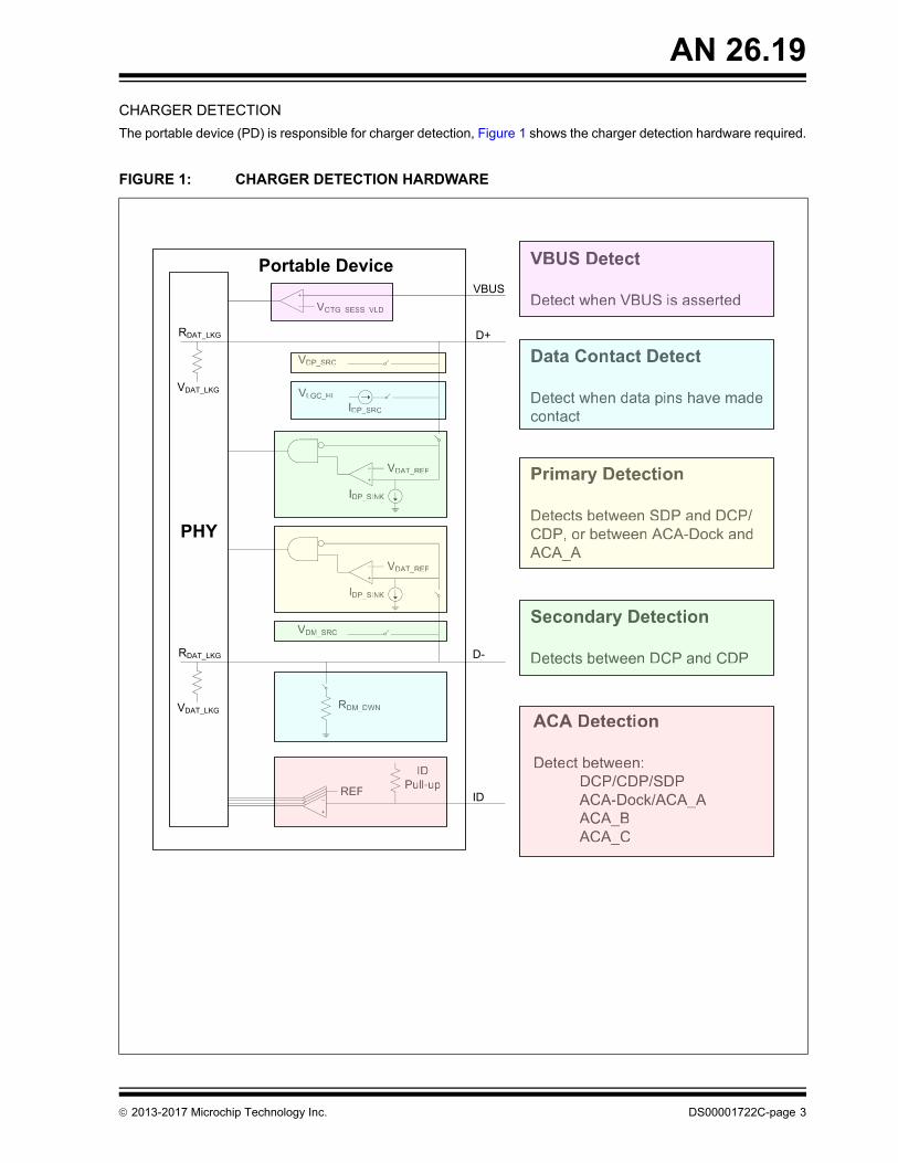
The portable device (PD) is responsible for charger detection, Figure 1 shows the charger detection hardware required.
FIGURE 1: CHARGER DETECTION HARDWARE
VDAT_REF
RDAT_LKG
VOTG_SESS_VLD
VLGC_HIIDP_SRC
VDAT_LKG
IDP_SINK
VDP_SRC
VDAT_REF
IDP_SINK
VDM_SRC
RDAT_LKG
VDAT_LKG RDM_DWN
REF
IDPull-up
ID
D-
D+
VBUS
Portable Device
PHY
VBUS Detect
Detect when VBUS is asserted
Data Contact Detect
Detect when data pins have madecontact
Primary Detection
Detects between SDP and DCP/CDP, or between ACA-Dock andACA_A
Secondary Detection
Detects between DCP and CDP
ACA Detection
Detect between:DCP/CDP/SDPACA-Dock/ACA_AACA_BACA_C
VBUS Detect
Detect when VBUS is asserted
Secondaryrr Detection
Detects between DCP and CDP
Primaryrr Detection
Detects between SDP and DCP/CDP, or between ACA-Dock andACA_A
Data Contact Detect
Detect when data pins have madecontact
ACA Detection
Detect between:DCP/CDP/SDPACA-Dock/A// CA_AACA_BACA_C
VOTG_SESS_VLD
RDM_DWN
VDAT_REF
IDP_SINK
VDAT_REF
IDP_SINK
REF
IDPull-up
VDP_SRC
VLGC_HIIDP_SRC
VDM_SRC
2013-2017 Microchip Technology Inc. DS00001722C-page 3

AN 26.19
There are five functional blocks as follows:
1. VBUS Detect - A portable device (PD) includes a session valid comparator, VBUS has to be above the VOTG_-
SESS_VLD threshold before the charger detection is initiated.
2. Data Contact Detect (DCD) - This is an optional block used to confirm that the data lines made contact during attachment. A current source IDP_SRC on D+ and a pulldown resistor RDM_DWN on D- are turned on. If the D+ line voltage drops, this indicates that data lines are attached to a charging port or a standard port and the logic pro-ceeds to start Primary Detection.
a) Figure 2 shows the DCD circuit when attached to a DCP port. Note that the D+ voltage will drop because it will be connected to pull-down resistor RDM_DWN through RDCP_DAT.
FIGURE 2: DATA CONTACT DETECT ON A DCP
Dedicated Charging Port Portable Device
5V VBUS
RDCP_DAT
DP
DM
< 200Ω
IDP_SRC
RDM_DWN
VLGC_HI
DS00001722C-page 4 2013-2017 Microchip Technology Inc.
AN 26.19
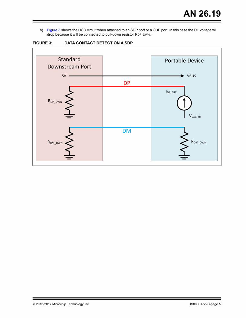
b) Figure 3 shows the DCD circuit when attached to an SDP port or a CDP port. In this case the D+ voltage will drop because it will be connected to pull-down resistor RDP_DWN.
FIGURE 3: DATA CONTACT DETECT ON A SDP
Standard Downstream Port
Portable Device
5V VBUS
RDP_DWN
DP
DM
IDP_SRC
RDM_DWN
VLGC_HI
RDM_DWN
2013-2017 Microchip Technology Inc. DS00001722C-page 5
AN 26.19
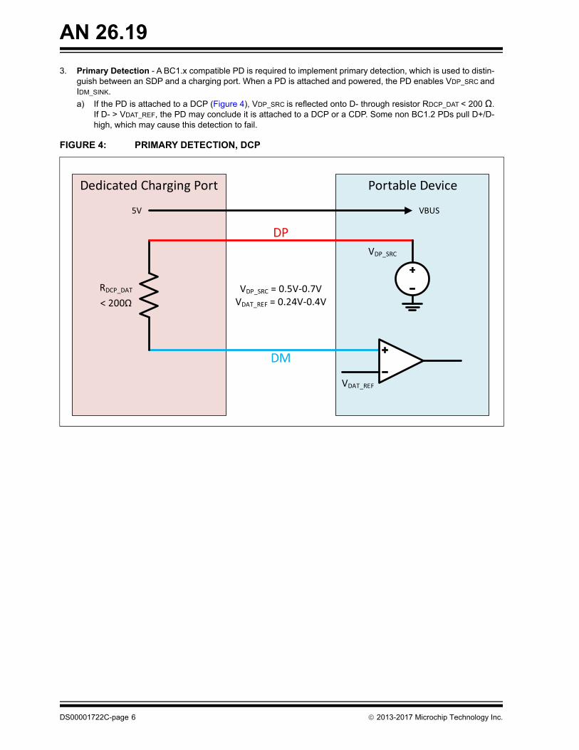
3. Primary Detection - A BC1.x compatible PD is required to implement primary detection, which is used to distin-guish between an SDP and a charging port. When a PD is attached and powered, the PD enables VDP_SRC and IDM_SINK.
a) If the PD is attached to a DCP (Figure 4), VDP_SRC is reflected onto D- through resistor RDCP_DAT < 200 Ω. If D- > VDAT_REF, the PD may conclude it is attached to a DCP or a CDP. Some non BC1.2 PDs pull D+/D- high, which may cause this detection to fail.
FIGURE 4: PRIMARY DETECTION, DCP
Dedicated Charging Port Portable Device
5V VBUS
VDAT_REF
RDCP_DAT
DP
DM
VDP_SRC = 0.5V-0.7VVDAT_REF = 0.24V-0.4V< 200Ω
VDP_SRC
DS00001722C-page 6 2013-2017 Microchip Technology Inc.
AN 26.19
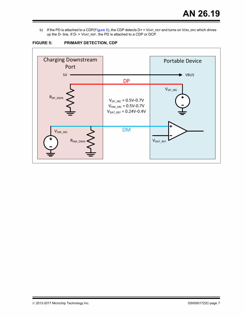
b) If the PD is attached to a CDP(Figure 5), the CDP detects D+ > VDAT_REF and turns on VDM_SRC which drives up the D- line. If D- > VDAT_REF, the PD is attached to a CDP or DCP.
FIGURE 5: PRIMARY DETECTION, CDP
Charging Downstream Port
Portable Device
5V VBUS
VDAT_REF
RDP_DWN
DP
DM
VDP_SRC = 0.5V-0.7VVDM_SRC = 0.5V-0.7V
VDAT_REF = 0.24V-0.4V
RDM_DWN
VDM_SRC
VDP_SRC
2013-2017 Microchip Technology Inc. DS00001722C-page 7
AN 26.19
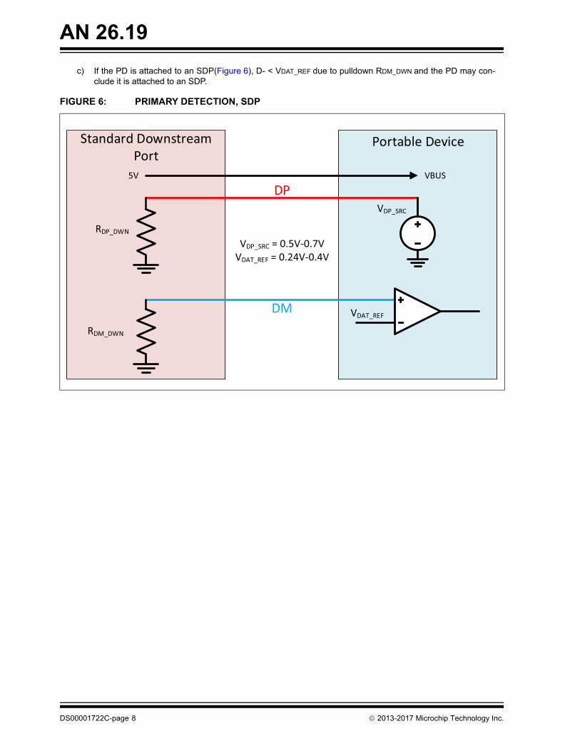
c) If the PD is attached to an SDP(Figure 6), D- < VDAT_REF due to pulldown RDM_DWN and the PD may con-clude it is attached to an SDP.
FIGURE 6: PRIMARY DETECTION, SDP
Standard Downstream Port
Portable Device
5V VBUS
VDAT_REF
RDP_DWN
DP
DM
VDP_SRC = 0.5V-0.7VVDAT_REF = 0.24V-0.4V
RDM_DWN
VDP_SRC
DS00001722C-page 8 2013-2017 Microchip Technology Inc.
AN 26.19
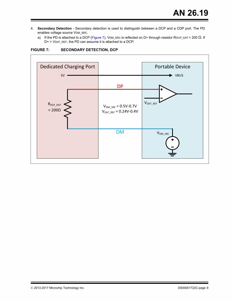
4. Secondary Detection - Secondary detection is used to distinguish between a DCP and a CDP port. The PD enables voltage source VDM_SRC.
a) If the PD is attached to a DCP (Figure 7), VDM_SRC is reflected on D+ through resistor RDCP_DAT < 200 Ω. If D+ > VDAT_REF, the PD can assume it is attached to a DCP.
FIGURE 7: SECONDARY DETECTION, DCP
Dedicated Charging Port Portable Device5V VBUS
RDCP_DAT
DP
DM
VDM_SRC = 0.5V-0.7VVDAT_REF = 0.24V-0.4V
VDM_SRC
< 200Ω
VDAT_REF
2013-2017 Microchip Technology Inc. DS00001722C-page 9
AN 26.19
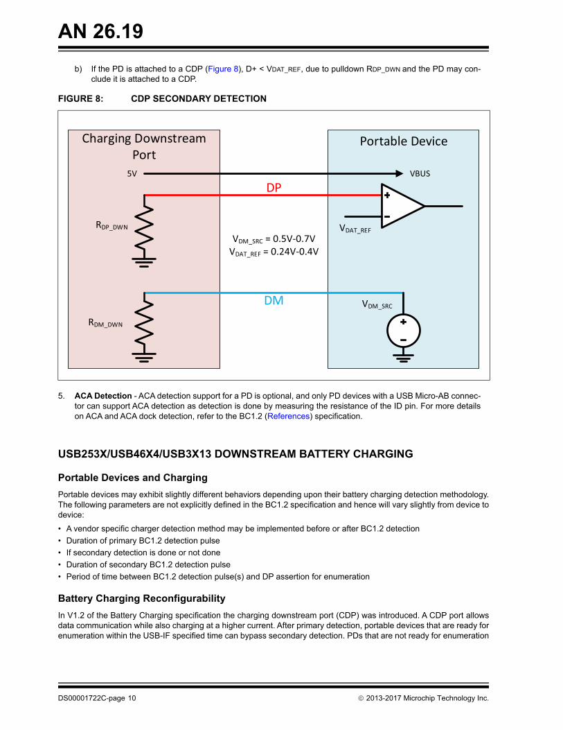
b) If the PD is attached to a CDP (Figure 8), D+ < VDAT_REF, due to pulldown RDP_DWN and the PD may con-clude it is attached to a CDP.
FIGURE 8: CDP SECONDARY DETECTION
Charging Downstream Port
Portable Device
5V VBUS
VDAT_REFRDP_DWN
DP
DM
VDM_SRC = 0.5V-0.7VVDAT_REF = 0.24V-0.4V
RDM_DWN
VDM_SRC
5. ACA Detection - ACA detection support for a PD is optional, and only PD devices with a USB Micro-AB connec-tor can support ACA detection as detection is done by measuring the resistance of the ID pin. For more details on ACA and ACA dock detection, refer to the BC1.2 (References) specification.
USB253X/USB46X4/USB3X13 DOWNSTREAM BATTERY CHARGING
Portable Devices and Charging
Portable devices may exhibit slightly different behaviors depending upon their battery charging detection methodology. The following parameters are not explicitly defined in the BC1.2 specification and hence will vary slightly from device to device:
• A vendor specific charger detection method may be implemented before or after BC1.2 detection
• Duration of primary BC1.2 detection pulse
• If secondary detection is done or not done
• Duration of secondary BC1.2 detection pulse
• Period of time between BC1.2 detection pulse(s) and DP assertion for enumeration
Battery Charging Reconfigurability
In V1.2 of the Battery Charging specification the charging downstream port (CDP) was introduced. A CDP port allows data communication while also charging at a higher current. After primary detection, portable devices that are ready for enumeration within the USB-IF specified time can bypass secondary detection. PDs that are not ready for enumeration
DS00001722C-page 10 2013-2017 Microchip Technology Inc.
AN 26.19
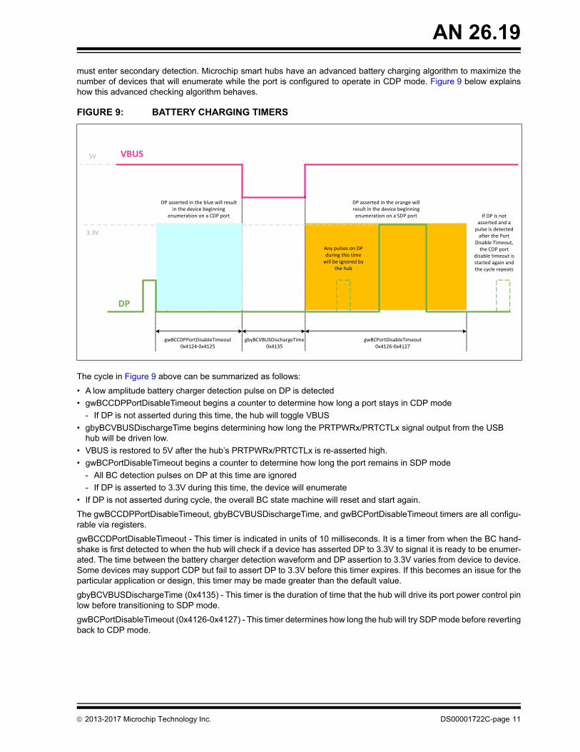
must enter secondary detection. Microchip smart hubs have an advanced battery charging algorithm to maximize the number of devices that will enumerate while the port is configured to operate in CDP mode. Figure 9 below explains how this advanced checking algorithm behaves.
FIGURE 9: BATTERY CHARGING TIMERS
gwBCCDPPortDisableTimeout0x4124‐0x4125
gwBCPortDisableTimeout0x4126‐0x4127
VBUS5V
gbyBCVBUSDischargeTime0x4135
DP
Any pulses on DP during this time will be ignored by
the hub
If DP is not asserted and a pulse is detected after the Port
Disable Timeout, the CDP port
disable timeout is started again and the cycle repeats
3.3V
DP asserted in the blue will result in the device beginning
enumeration on a CDP port
DP asserted in the orange will result in the device beginning enumeration on a SDP port
The cycle in Figure 9 above can be summarized as follows:
• A low amplitude battery charger detection pulse on DP is detected
• gwBCCDPPortDisableTimeout begins a counter to determine how long a port stays in CDP mode
- If DP is not asserted during this time, the hub will toggle VBUS
• gbyBCVBUSDischargeTime begins determining how long the PRTPWRx/PRTCTLx signal output from the USB hub will be driven low.
• VBUS is restored to 5V after the hub’s PRTPWRx/PRTCTLx is re-asserted high.
• gwBCPortDisableTimeout begins a counter to determine how long the port remains in SDP mode
- All BC detection pulses on DP at this time are ignored
- If DP is asserted to 3.3V during this time, the device will enumerate
• If DP is not asserted during cycle, the overall BC state machine will reset and start again.
The gwBCCDPPortDisableTimeout, gbyBCVBUSDischargeTime, and gwBCPortDisableTimeout timers are all configu-rable via registers.
gwBCCDPortDisableTimeout - This timer is indicated in units of 10 milliseconds. It is a timer from when the BC hand-shake is first detected to when the hub will check if a device has asserted DP to 3.3V to signal it is ready to be enumer-ated. The time between the battery charger detection waveform and DP assertion to 3.3V varies from device to device. Some devices may support CDP but fail to assert DP to 3.3V before this timer expires. If this becomes an issue for the particular application or design, this timer may be made greater than the default value.
gbyBCVBUSDischargeTime (0x4135) - This timer is the duration of time that the hub will drive its port power control pin low before transitioning to SDP mode.
gwBCPortDisableTimeout (0x4126-0x4127) - This timer determines how long the hub will try SDP mode before reverting back to CDP mode.
2013-2017 Microchip Technology Inc. DS00001722C-page 11
AN 26.19
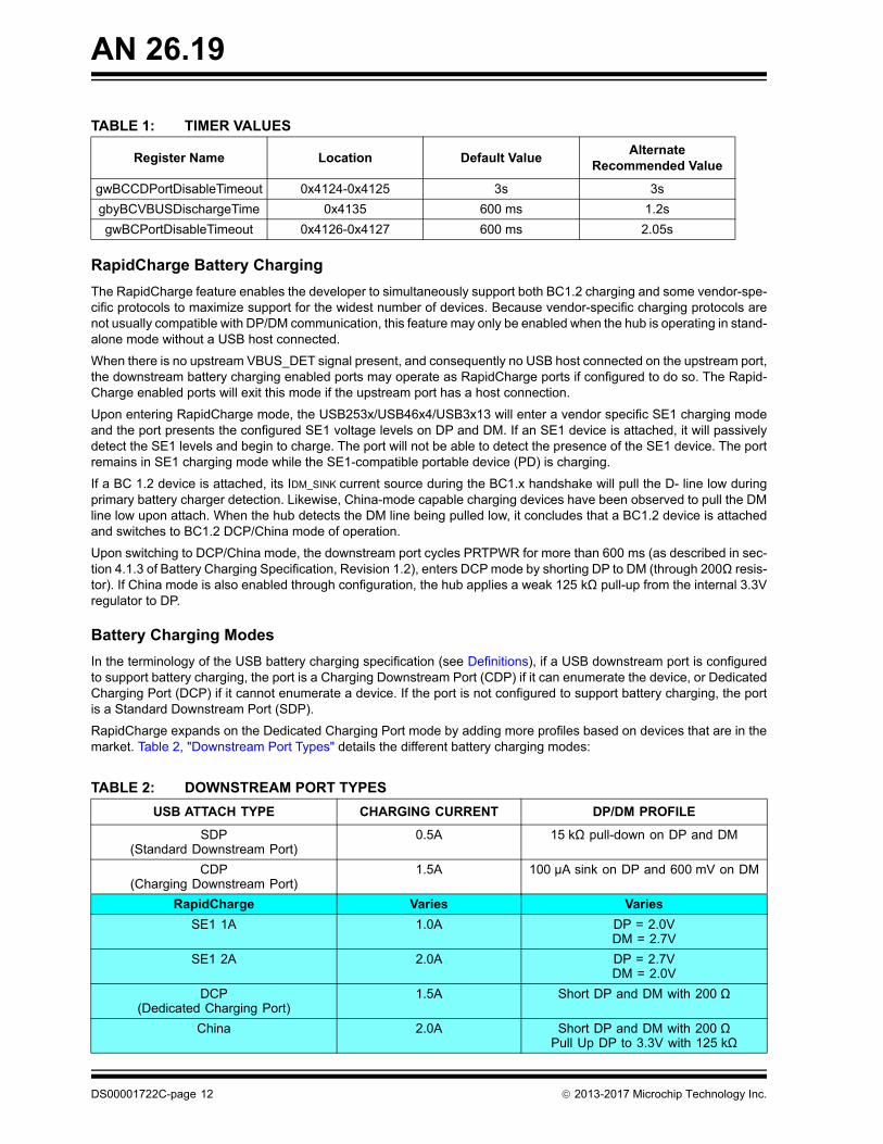
TABLE 1: TIMER VALUES
Register Name Location Default ValueAlternate
Recommended Value
gwBCCDPortDisableTimeout 0x4124-0x4125 3s 3s
gbyBCVBUSDischargeTime 0x4135 600 ms 1.2s
gwBCPortDisableTimeout 0x4126-0x4127 600 ms 2.05s
RapidCharge Battery Charging
The RapidCharge feature enables the developer to simultaneously support both BC1.2 charging and some vendor-spe-cific protocols to maximize support for the widest number of devices. Because vendor-specific charging protocols are not usually compatible with DP/DM communication, this feature may only be enabled when the hub is operating in stand-alone mode without a USB host connected.
When there is no upstream VBUS_DET signal present, and consequently no USB host connected on the upstream port, the downstream battery charging enabled ports may operate as RapidCharge ports if configured to do so. The Rapid-Charge enabled ports will exit this mode if the upstream port has a host connection.
Upon entering RapidCharge mode, the USB253x/USB46x4/USB3x13 will enter a vendor specific SE1 charging mode and the port presents the configured SE1 voltage levels on DP and DM. If an SE1 device is attached, it will passively detect the SE1 levels and begin to charge. The port will not be able to detect the presence of the SE1 device. The port remains in SE1 charging mode while the SE1-compatible portable device (PD) is charging.
If a BC 1.2 device is attached, its IDM_SINK current source during the BC1.x handshake will pull the D- line low during primary battery charger detection. Likewise, China-mode capable charging devices have been observed to pull the DM line low upon attach. When the hub detects the DM line being pulled low, it concludes that a BC1.2 device is attached and switches to BC1.2 DCP/China mode of operation.
Upon switching to DCP/China mode, the downstream port cycles PRTPWR for more than 600 ms (as described in sec-tion 4.1.3 of Battery Charging Specification, Revision 1.2), enters DCP mode by shorting DP to DM (through 200Ω resis-tor). If China mode is also enabled through configuration, the hub applies a weak 125 kΩ pull-up from the internal 3.3V regulator to DP.
Battery Charging Modes
In the terminology of the USB battery charging specification (see Definitions), if a USB downstream port is configured to support battery charging, the port is a Charging Downstream Port (CDP) if it can enumerate the device, or Dedicated Charging Port (DCP) if it cannot enumerate a device. If the port is not configured to support battery charging, the port is a Standard Downstream Port (SDP).
RapidCharge expands on the Dedicated Charging Port mode by adding more profiles based on devices that are in the market. Table 2, "Downstream Port Types" details the different battery charging modes:
TABLE 2: DOWNSTREAM PORT TYPES
USB ATTACH TYPE CHARGING CURRENT DP/DM PROFILE
SDP(Standard Downstream Port)
0.5A 15 kΩ pull-down on DP and DM
CDP (Charging Downstream Port)
1.5A 100 µA sink on DP and 600 mV on DM
RapidCharge Varies Varies
SE1 1A 1.0A DP = 2.0VDM = 2.7V
SE1 2A 2.0A DP = 2.7VDM = 2.0V
DCP(Dedicated Charging Port)
1.5A Short DP and DM with 200 Ω
China 2.0A Short DP and DM with 200 ΩPull Up DP to 3.3V with 125 kΩ
DS00001722C-page 12 2013-2017 Microchip Technology Inc.
AN 26.19
Battery Charging Configuration
The USB253x/USB46x4/USB3x13 downstream ports can be enabled for battery charging by adding a pullup resistor (10 kΩ) on the battery charging configuration strap (BC_ENx) for corresponding port x. These straps are sampled at reset. If they are sampled high, the corresponding port is enabled for battery charging. For specific pin locations, refer to the device’s datasheet (References).
Battery charging can also be enabled by use of the battery charging configuration registers that reside in the USB253x/USB46x4/USB3x13. These configuration registers are used by the internal ROM firmware to configure the battery charging functionality for each port. These registers can be modified by a configuration programmed in the One Time Programmable (OTP) memory using the Protouch tool (see ProTouch Programming Tool). The battery charging config-uration registers defaults to 0x00 at reset if the configuration strap pullups are not present and to 0xD3 for the corre-sponding port if the BC_EN strap is present. There is a configuration register for each port. The configuration register fields can be found in the SMBus Slave application note found in the references section (References).
Battery Charging Operation in CDP Mode
The battery charging enabled ports will exit DCP mode and enter CDP mode if the upstream port receives a host con-nection. On detection of the USB host SET_ADDRESS command, any BC enabled port will be turned off for at least 600 mS before it is turned on again. If the host sends a command to turn on port power before this time, the command will be delayed appropriately. If the command is received after the timer has expired, it will be executed immediately. In this mode the port power will be controlled by the USB host. Overcurrent events in CDP mode will be reported to the host.
The battery charging enabled ports will exit this mode and go into DCP mode if the upstream port loses the host con-nection or VBUS goes away. During the transition, any BC enable port will be turned off then on again.
VBUS Voltage Drop and Battery Charging
During battery charging as the current output is increased the VBUS voltage will drop due to resistive losses. The RDS ON resistance of the MOSFET on a typical port power controller (PPC) could be as high as 140 mΩ. At 1A this is 140 mV, if the input to the PPC is 5V, VBUS will be 4.86V. Some battery charging devices may not charge at high current if VBUS drops significantly below 5V, also the battery will charge faster at a higher voltage. For these reasons it is highly recommended to provide 5.2V at the input of the PPC. With 5.2V at the PPC input and a 1A load VBUS would be 5.06V.
System Level Considerations
ATTACHED VERSUS CONNECTED
When enabled, Battery Charging is supported in all states when attached and powered but not connected, this means that battery charging is supported at all times there is power.
HOST CONTROL OF BATTERY CHARGING
There is no specified handshake between the Hub and Host to support battery charging on the downstream ports. Bat-tery charging on the downstream port is a completely local event, with no reporting done to the host.
CHARGING WHILE SUSPENDED OR UNCONFIGURED
Battery charging is supported while the system is suspended or unconfigured. USB-IF requires low current consumption on VBUS while in suspend, but not from other supplies. The only requirement is for bus powered devices which does not apply to a charging Hub.
Managing Overcurrent
The USB253x/USB46x4/USB3x13 is responsible for managing overcurrent shutdown (OCS) events. For battery charging ports, PRTPWR is driven high (asserted) after hardware initialization.
If an OCS event occurs, the PRTPWR is negated. When the Hub is configured in ganged port power control, all PRT-PWR pins will be negated. With individual control, only the PRTPWR that experienced the OCS event will be negated.
An OCS event is acknowledged and reported to the Host when the Hub is enumerated. After an OCS event, the USB253x/USB46x4/USB3x13 will always deassert PRT_PWR.
2013-2017 Microchip Technology Inc. DS00001722C-page 13

AN 26.19
Note: The USB3813 do not include individual port control enable signals for each port. Because of this, if one port has an over current event, all ports will be disabled.
RAPIDCHARGE MODE OVERCURRENT
If there is an overcurrent event in RapidCharge mode, the port is turned off for one second, then re-enabled. If the OCS event persists, the cycle is repeated for a total or three times. If after three attempts the OCS still persists, the cycle is still repeated, but with a retry interval of ten seconds. Continuous retries prevent defective devices from disabling the port.
CDP, SDP MODE OVERCURRENT
In CDP or SDP mode there is a USB host present, port power is controlled by the USB host, and OCS events are han-dled by the host.
The OCS event does not have to be registered. When and if the hub is connected to a host, the host will initialize the hub and turn on its port power. If the overcurrent condition still exist, the host will be notified.
ProTouch Programming Tool
The ProTouch tool is a developed tool used for configuration and programming of the USB253x/USB46x4/USB3x13 Hub controller. It can be used for development and prototyping where a single part is programmed or for multiple parts in a manufacturing environment. For more information refer to the Protouch MPT User Manual (References).
USB253X/USB46X4/USB3X13 UPSTREAM BATTERY CHARGER DETECTION
Overview
The USB253x/USB46x4/USB3x13 hub controller includes the capability for USB upstream battery charger detection, which is used for implementing portable devices with USB charging. To have the best possibility of detecting the pres-ence of a charger, it is important to detect not only USB-IF BC1.2 compliant chargers but also SE1 chargers and char-gers compliant with the Chinese Telecommunications Industry battery charger specification YD/T 1591-2009. The USB253x/USB46x4/USB3x13 implements a universal charger detection sequence that includes all these protocols for charger detection.
Charger Detection Types
The detection sequence is intended to identify chargers which conform to the Chinese Telecommunications Industry charger specification, chargers which conform to the USB-IF Battery Charger Specification 1.2, and single ended 1 char-gers (SE1). The types of chargers detected is shown in Table 3.
TABLE 3: CHARGERS COMPATIBLE WITH UPSTREAM DETECTION
USB ATTACH TYPE DP/DM PROFILE CHARGERTYPE
DCP(Dedicated Charging Port)
Shorted < 200 Ω 001
CDP (Charging Downstream Port)
VDP reflected to VDM 010(EnhancedChrgDet = 1)
SDP(Standard Downstream Port)
USB Host or downstream hub port
15 kΩ pull-down on DP and DM 011
SE1 Charger Low Current Charger DP=2.0 VDM=2.0 V
100
SE1 Charger High Current Charger DP=2.0 VDM=2.7 V
101
SE1 Super High Current Charger DP=2.7 VDM=2.0 V
110
DS00001722C-page 14 2013-2017 Microchip Technology Inc.
AN 26.19
Once the charger detection sequence is initiated, the device provides feedback to the system through the SMBus run-time registers, the INT_N, and the CHRGDET outputs. An external microcontroller can access these registers via the I2C/SMBus interface. Refer to the SMBus Slave Interface for the USB253x/USB3x13/USB46x4 application note (References) for SMBus register details.
The type of the detected charger is returned in the ChargerType field in the Upstream Battery Charger Detection (UP_B-C_DET) Register. The CHG_DET field encodes the current that can be drawn from the USB upstream port.
The CHG_DET bits are reflected in the CHRGDET pins (USB3813 only), these are useful for situations where the pro-cessor cannot access these registers, such as with a dead battery condition. These pins can be connected to external hardware, for example a power management IC (PMIC).
There are some registers like the Upstream Custom Battery Charger Control (UP_CUST_BC_CTL) and the Upstream Custom Battery Charger Status (UP_CUST_BC_STAT) available for implementing custom charger detection algo-rithms.
The following sections detail the sequence followed for battery charger detection depending on whether the automatic default sequence is utilized, or external MCU control is utilized.
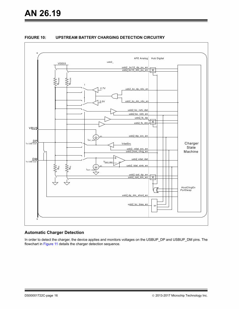
Charger Detection Circuitry
The charger detection circuitry shown in Figure 10 is used to detect the type of charger attached to the upstream USB connector.
2013-2017 Microchip Technology Inc. DS00001722C-page 15
AN 26.19
FIGURE 10: UPSTREAM BATTERY CHARGING DETECTION CIRCUITRY
VDAT_ REF
DP
~~
~~
VBUS
To USB Con.
en
DMTo USB Con.
IDAT_ SINK
en
VdatSrc
IDP_ SRC
en
RP
D
RP
D
Charger State
Machine
PortSwap
AFE Analog Hub Digital
HostChrgEn
usb2_ idp_src_en
usb2_ vdat_src_enusb2_host_ chrg_en
usb2_ idat_ sink_en
usb2_ vdat_det
usb2_dp_ dm_ short_en
_ _ _
usb2 _bc10_dp_pu_enusb2_bc10_dm_pu_en
usb2_bc rxhi_en
usb2_fs_dp
usb2_fs_dm
usb2_bc_ bias_en
usb2_ rpd_dp_enusb2_ rpd_dm_en
RP
U12
5K
RP
U12
5K
VDD33
or
usb2_bc_ rxhi_det
I
usb2_
usb2_bc_dp_rdiv_en
usb2_bc_dm_rdiv_en
2.7V
2.0V
Automatic Charger Detection
In order to detect the charger, the device applies and monitors voltages on the USBUP_DP and USBUP_DM pins. The flowchart in Figure 11 details the charger detection sequence.
DS00001722C-page 16 2013-2017 Microchip Technology Inc.
AN 26.19
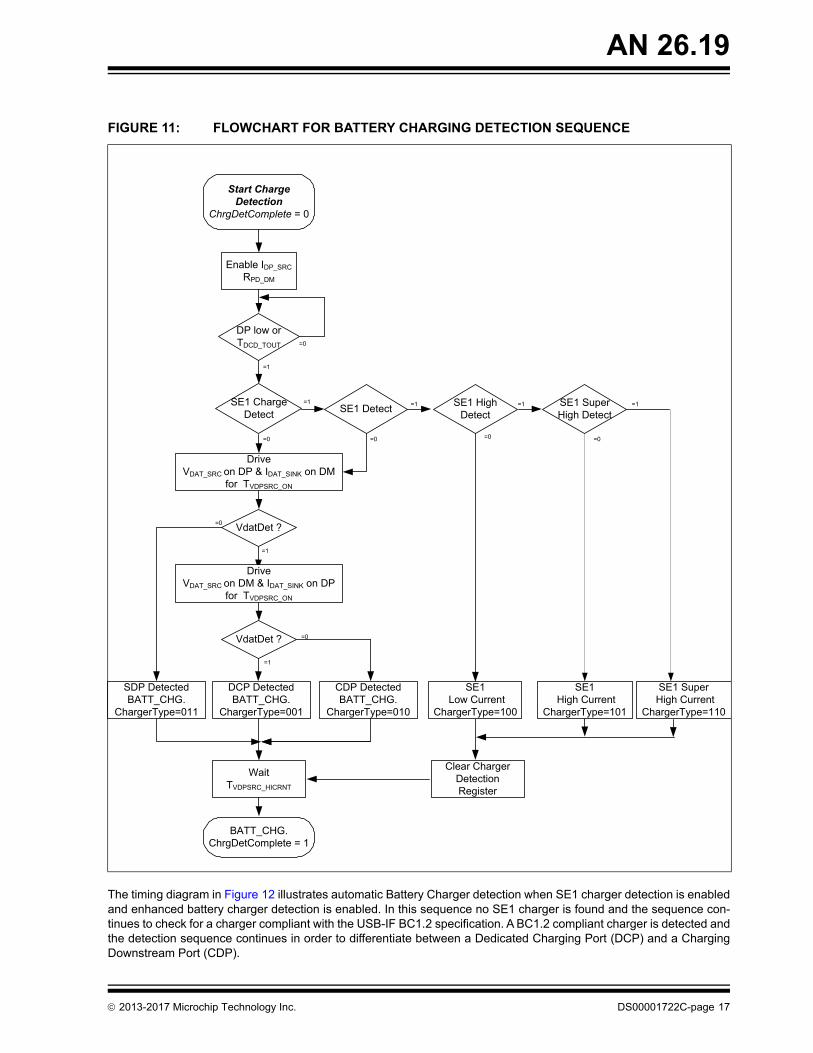
FIGURE 11: FLOWCHART FOR BATTERY CHARGING DETECTION SEQUENCE
Start Charge Detection
ChrgDetComplete = 0
VdatDet ?
=1
=0
Wait TVDPSRC_HICRNT
SDP DetectedBATT_CHG.
ChargerType=011
=0
Enable IDP_SRC
RPD_DM
=1
=0
=0
DCP DetectedBATT_CHG.
ChargerType=001
CDP DetectedBATT_CHG.
ChargerType=010
DriveVDAT_SRC on DP & IDAT_SINK on DM
for TVDPSRC_ON
DP low orTDCD_TOUT
SE1 Charge Detect SE1 Detect
VdatDet ?
=1
DriveVDAT_SRC on DM & IDAT_SINK on DP
for TVDPSRC_ON
BATT_CHG.ChrgDetComplete = 1
Clear ChargerDetectionRegister
SE1 High Detect
SE1 Super High Detect
SE1 Low Current
ChargerType=100
SE1 High Current
ChargerType=101
SE1 Super High Current
ChargerType=110
=0
=1 =1 =1 =1
=0 =0
=0
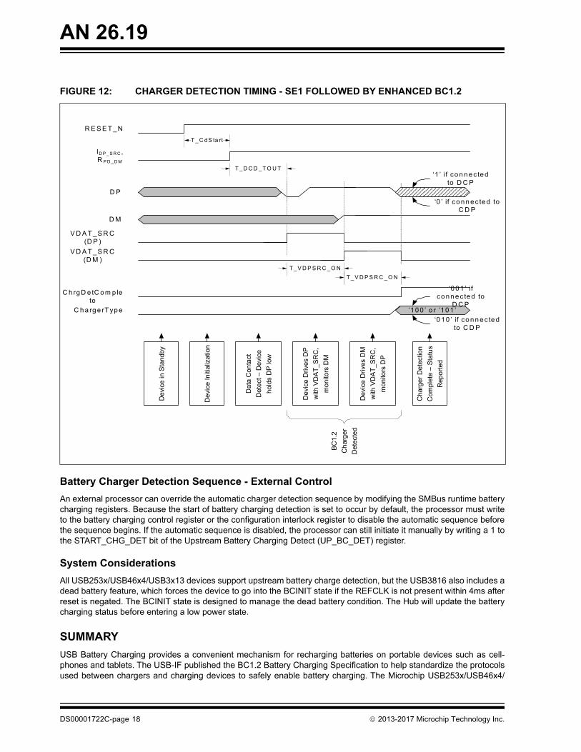
The timing diagram in Figure 12 illustrates automatic Battery Charger detection when SE1 charger detection is enabled and enhanced battery charger detection is enabled. In this sequence no SE1 charger is found and the sequence con-tinues to check for a charger compliant with the USB-IF BC1.2 specification. A BC1.2 compliant charger is detected and the detection sequence continues in order to differentiate between a Dedicated Charging Port (DCP) and a Charging Downstream Port (CDP).
2013-2017 Microchip Technology Inc. DS00001722C-page 17
AN 26.19
FIGURE 12: CHARGER DETECTION TIMING - SE1 FOLLOWED BY ENHANCED BC1.2
R E S E T _N
ID P _ S R C ,R P D _ D M
D P
C h a rg e rT yp e
C h rg D e tC o m p lete
T _ C d S ta rt
T _ D C D _ T O U T
D M
‘1 0 0 ’ o r ‘1 0 1 ’
V D A T _S R C (D P )
T _V D P S R C _ O N
T _V D P S R C _ O N
V D A T _S R C (D M )
‘1 ’ if co n n e c te d to D C P
‘0 ’ if co n n ec te d to C D P
‘0 0 1 ’ if co nn e c te d to
D C P
‘0 1 0 ’ if co n n e c te d to C D P
De
vice
in S
tand
by
Dev
ice
Initi
aliz
atio
n
Dat
a C
on
tact
Det
ect –
Dev
ice
hold
s D
P lo
w
Cha
rger
Det
ectio
n
Co
mp
lete
– S
tatu
s
Re
po
rte
d
De
vice
Dri
ves
DP
with
VD
AT
_S
RC
,
mo
nito
rs D
M
Dev
ice
Dri
ves
DM
with
VD
AT
_S
RC
,
mo
nito
rs D
P
BC
1.2
Ch
arg
er
De
tect
ed
Battery Charger Detection Sequence - External Control
An external processor can override the automatic charger detection sequence by modifying the SMBus runtime battery charging registers. Because the start of battery charging detection is set to occur by default, the processor must write to the battery charging control register or the configuration interlock register to disable the automatic sequence before the sequence begins. If the automatic sequence is disabled, the processor can still initiate it manually by writing a 1 to the START_CHG_DET bit of the Upstream Battery Charging Detect (UP_BC_DET) register.
System Considerations
All USB253x/USB46x4/USB3x13 devices support upstream battery charge detection, but the USB3816 also includes a dead battery feature, which forces the device to go into the BCINIT state if the REFCLK is not present within 4ms after reset is negated. The BCINIT state is designed to manage the dead battery condition. The Hub will update the battery charging status before entering a low power state.
SUMMARY
USB Battery Charging provides a convenient mechanism for recharging batteries on portable devices such as cell-phones and tablets. The USB-IF published the BC1.2 Battery Charging Specification to help standardize the protocols used between chargers and charging devices to safely enable battery charging. The Microchip USB253x/USB46x4/
DS00001722C-page 18 2013-2017 Microchip Technology Inc.
AN 26.19
USB3x13 Hub Controller with RapidCharge provides battery charging protocols that include legacy, SE1, Chinese Tele-communications Industry YD/T 1591-2009, and USBIF BC1.2 to implement a battery charging solution supporting devices from Apple®, Samsung, and most other devices.
The Microchip USB253x/USB46x4/USB3x13 Hub Controller also supports battery charger detection for use in portable devices that require USB charger detection capability.
2013-2017 Microchip Technology Inc. DS00001722C-page 19
AN 26.19
APPENDIX A: APPLICATION NOTE REVISION HISTORY
TABLE A-1: REVISION HISTORY
Revision Level & Date Section/Figure/Entry Correction
Rev. C (03-29-17) All • Updated Sales Listing and cover pages.
• Various minor formatting issues addressed.
• Various typographical and grammatical issues addressed.
Section , "USB253x/USB46x4/USB3x13 Down-stream battery charging," on page 10
• Updated section
• Updated figures
Rev. B (9-9-14) Section , "VBUS Voltage Drop and Battery Charging," on page 13
Added section.
Rev. A (4-29-14) DS00001722A replaces the previous SMSC version, Revision 1.1.
Rev. 1.2 (8-27-14) Section , "VBUS Voltage Drop and Battery Charging," on page 13
Added section.
Rev. 1.1 (12-04-13) Section , "Definitions," on page 1
Updated definitions.
Section , "Overview," on page 2, Section , "Non-Stan-dard Battery Charging Solu-tions," on page 2
Entirely updated.
Section , "Charger Detec-tion," on page 3, Figure 2, and Figure 3
Updated item 2 and 4 descriptions. Updated listedfigures.
Section , "USB253x/USB46x4/USB3x13 Down-stream battery charging," on page 10
Updated entirety of chapter.
Section , "USB253x/USB46x4/USB3x13 Upstream Battery Charger Detection," on page 14
Updated entirety of chapter.
Rev. 1.0 (06-06-13) Document release
DS00001722C-page 20 2013-2017 Microchip Technology Inc.

AN 26.19
NOTES:
2013-2017 Microchip Technology Inc. DS00001722C-page 21
AN 26.19
DS00001722C-page 22 2013-2017 Microchip Technology Inc.
THE MICROCHIP WEB SITE
Microchip provides online support via our WWW site at www.microchip.com. This web site is used as a means to make files and information easily available to customers. Accessible by using your favorite Internet browser, the web site contains the following information:
• Product Support – Data sheets and errata, application notes and sample programs, design resources, user’s guides and hardware support documents, latest software releases and archived software
• General Technical Support – Frequently Asked Questions (FAQ), technical support requests, online discussion groups, Microchip consultant program member listing
• Business of Microchip – Product selector and ordering guides, latest Microchip press releases, listing of seminars and events, listings of Microchip sales offices, distributors and factory representatives
CUSTOMER CHANGE NOTIFICATION SERVICE
Microchip’s customer notification service helps keep customers current on Microchip products. Subscribers will receive e-mail notification whenever there are changes, updates, revisions or errata related to a specified product family or development tool of interest.
To register, access the Microchip web site at www.microchip.com. Under “Support”, click on “Customer Change Notifi-cation” and follow the registration instructions.
CUSTOMER SUPPORT
Users of Microchip products can receive assistance through several channels:
• Distributor or Representative
• Local Sales Office
• Field Application Engineer (FAE)
• Technical Support
Customers should contact their distributor, representative or Field Application Engineer (FAE) for support. Local sales offices are also available to help customers. A listing of sales offices and locations is included in the back of this document.
Technical support is available through the web site at: http://microchip.com/support
2013-2017 Microchip Technology Inc. DS00001722C-page 23
AN 26.19
Information contained in this publication regarding device applications and the like is provided only for your convenience and may be superseded by updates. It is your responsibility to ensure that your application meets with your specifications. MICROCHIP MAKES NO REPRESENTATIONS OR WARRANTIES OF ANY KIND WHETHER EXPRESS OR IMPLIED, WRITTEN OR ORAL, STATUTORY OR OTHERWISE, RELATED TO THE INFORMATION, INCLUDING BUT NOT LIMITED TO ITS CONDITION, QUALITY, PERFORMANCE, MERCHANTABILITY OR FITNESS FOR PURPOSE. Microchip disclaims all liability arising from this information and its use. Use of Micro-chip devices in life support and/or safety applications is entirely at the buyer’s risk, and the buyer agrees to defend, indemnify and hold harmless Microchip from any and all damages, claims, suits, or expenses resulting from such use. No licenses are conveyed, implicitly or otherwise, under any Microchip intellectual property rights unless otherwise stated.
Trademarks
The Microchip name and logo, the Microchip logo, AnyRate, AVR, AVR logo, AVR Freaks, BeaconThings, BitCloud, CryptoMemory, CryptoRF, dsPIC, FlashFlex, flexPWR, Heldo, JukeBlox, KEELOQ, KEELOQ logo, Kleer, LANCheck, LINK MD, maXStylus, maXTouch, MediaLB, megaAVR, MOST, MOST logo, MPLAB, OptoLyzer, PIC, picoPower, PICSTART, PIC32 logo, Prochip Designer, QTouch, RightTouch, SAM-BA, SpyNIC, SST, SST Logo, SuperFlash, tinyAVR, UNI/O, and XMEGA are registered trademarks of Microchip Technology Incorporated in the U.S.A. and other countries.
ClockWorks, The Embedded Control Solutions Company, EtherSynch, Hyper Speed Control, HyperLight Load, IntelliMOS, mTouch, Precision Edge, and Quiet-Wire are registered trademarks of Microchip Technology Incorporated in the U.S.A.
Adjacent Key Suppression, AKS, Analog-for-the-Digital Age, Any Capacitor, AnyIn, AnyOut, BodyCom, chipKIT, chipKIT logo, CodeGuard, CryptoAuthentication, CryptoCompanion, CryptoController, dsPICDEM, dsPICDEM.net, Dynamic Average Matching, DAM, ECAN, EtherGREEN, In-Circuit Serial Programming, ICSP, Inter-Chip Connectivity, JitterBlocker, KleerNet, KleerNet logo, Mindi, MiWi, motorBench, MPASM, MPF, MPLAB Certified logo, MPLIB, MPLINK, MultiTRAK, NetDetach, Omniscient Code Generation, PICDEM, PICDEM.net, PICkit, PICtail, PureSilicon, QMatrix, RightTouch logo, REAL ICE, Ripple Blocker, SAM-ICE, Serial Quad I/O, SMART-I.S., SQI, SuperSwitcher, SuperSwitcher II, Total Endurance, TSHARC, USBCheck, VariSense, ViewSpan, WiperLock, Wireless DNA, and ZENA are trademarks of Microchip Technology Incorporated in the U.S.A. and other countries.
SQTP is a service mark of Microchip Technology Incorporated in the U.S.A.
Silicon Storage Technology is a registered trademark of Microchip Technology Inc. in other countries.
GestIC is a registered trademark of Microchip Technology Germany II GmbH & Co. KG, a subsidiary of Microchip Technology Inc., in other countries.
All other trademarks mentioned herein are property of their respective companies.
© 2013-2017, Microchip Technology Incorporated, All Rights Reserved.
ISBN: 978-1-5224-1533-6
Note the following details of the code protection feature on Microchip devices:
• Microchip products meet the specification contained in their particular Microchip Data Sheet.
• Microchip believes that its family of products is one of the most secure families of its kind on the market today, when used in the intended manner and under normal conditions.
• There are dishonest and possibly illegal methods used to breach the code protection feature. All of these methods, to our knowledge, require using the Microchip products in a manner outside the operating specifications contained in Microchip’s Data Sheets. Most likely, the person doing so is engaged in theft of intellectual property.
• Microchip is willing to work with the customer who is concerned about the integrity of their code.
• Neither Microchip nor any other semiconductor manufacturer can guarantee the security of their code. Code protection does not mean that we are guaranteeing the product as “unbreakable.”
Code protection is constantly evolving. We at Microchip are committed to continuously improving the code protection features of our products. Attempts to break Microchip’s code protection feature may be a violation of the Digital Millennium Copyright Act. If such acts allow unauthorized access to your software or other copyrighted work, you may have a right to sue for relief under that Act.
Microchip received ISO/TS-16949:2009 certification for its worldwide headquarters, design and wafer fabrication facilities in Chandler and Tempe, Arizona; Gresham, Oregon and design centers in California and India. The Company’s quality system processes and procedures are for its PIC® MCUs and dsPIC® DSCs, KEELOQ® code hopping devices, Serial EEPROMs, microperipherals, nonvolatile memory and analog products. In addition, Microchip’s quality system for the design and manufacture of development systems is ISO 9001:2000 certified.
QUALITYMANAGEMENTSYSTEMCERTIFIEDBYDNV
== ISO/TS16949==

DS00001722C-page 24 2013-2017 Microchip Technology Inc.
AMERICASCorporate Office2355 West Chandler Blvd.Chandler, AZ 85224-6199Tel: 480-792-7200 Fax: 480-792-7277Technical Support: http://www.microchip.com/supportWeb Address: www.microchip.com
AtlantaDuluth, GA Tel: 678-957-9614 Fax: 678-957-1455
Austin, TXTel: 512-257-3370
BostonWestborough, MA Tel: 774-760-0087 Fax: 774-760-0088
ChicagoItasca, IL Tel: 630-285-0071 Fax: 630-285-0075
DallasAddison, TX Tel: 972-818-7423 Fax: 972-818-2924
DetroitNovi, MI Tel: 248-848-4000
Houston, TX Tel: 281-894-5983
IndianapolisNoblesville, IN Tel: 317-773-8323Fax: 317-773-5453Tel: 317-536-2380
Los AngelesMission Viejo, CA Tel: 949-462-9523Fax: 949-462-9608Tel: 951-273-7800
Raleigh, NC Tel: 919-844-7510
New York, NY Tel: 631-435-6000
San Jose, CA Tel: 408-735-9110Tel: 408-436-4270
Canada - TorontoTel: 905-695-1980 Fax: 905-695-2078
ASIA/PACIFICAsia Pacific OfficeSuites 3707-14, 37th FloorTower 6, The GatewayHarbour City, Kowloon
Hong KongTel: 852-2943-5100Fax: 852-2401-3431
Australia - SydneyTel: 61-2-9868-6733Fax: 61-2-9868-6755
China - BeijingTel: 86-10-8569-7000 Fax: 86-10-8528-2104
China - ChengduTel: 86-28-8665-5511Fax: 86-28-8665-7889
China - ChongqingTel: 86-23-8980-9588Fax: 86-23-8980-9500
China - DongguanTel: 86-769-8702-9880
China - GuangzhouTel: 86-20-8755-8029
China - HangzhouTel: 86-571-8792-8115 Fax: 86-571-8792-8116
China - Hong Kong SARTel: 852-2943-5100 Fax: 852-2401-3431
China - NanjingTel: 86-25-8473-2460Fax: 86-25-8473-2470
China - QingdaoTel: 86-532-8502-7355Fax: 86-532-8502-7205
China - ShanghaiTel: 86-21-3326-8000 Fax: 86-21-3326-8021
China - ShenyangTel: 86-24-2334-2829Fax: 86-24-2334-2393
China - ShenzhenTel: 86-755-8864-2200 Fax: 86-755-8203-1760
China - WuhanTel: 86-27-5980-5300Fax: 86-27-5980-5118
China - XianTel: 86-29-8833-7252Fax: 86-29-8833-7256
ASIA/PACIFICChina - XiamenTel: 86-592-2388138 Fax: 86-592-2388130
China - ZhuhaiTel: 86-756-3210040 Fax: 86-756-3210049
India - BangaloreTel: 91-80-3090-4444 Fax: 91-80-3090-4123
India - New DelhiTel: 91-11-4160-8631Fax: 91-11-4160-8632
India - PuneTel: 91-20-3019-1500
Japan - OsakaTel: 81-6-6152-7160 Fax: 81-6-6152-9310
Japan - TokyoTel: 81-3-6880- 3770 Fax: 81-3-6880-3771
Korea - DaeguTel: 82-53-744-4301Fax: 82-53-744-4302
Korea - SeoulTel: 82-2-554-7200Fax: 82-2-558-5932 or 82-2-558-5934
Malaysia - Kuala LumpurTel: 60-3-6201-9857Fax: 60-3-6201-9859
Malaysia - PenangTel: 60-4-227-8870Fax: 60-4-227-4068
Philippines - ManilaTel: 63-2-634-9065Fax: 63-2-634-9069
SingaporeTel: 65-6334-8870Fax: 65-6334-8850
Taiwan - Hsin ChuTel: 886-3-5778-366Fax: 886-3-5770-955
Taiwan - KaohsiungTel: 886-7-213-7830
Taiwan - TaipeiTel: 886-2-2508-8600 Fax: 886-2-2508-0102
Thailand - BangkokTel: 66-2-694-1351Fax: 66-2-694-1350
EUROPEAustria - WelsTel: 43-7242-2244-39Fax: 43-7242-2244-393
Denmark - CopenhagenTel: 45-4450-2828 Fax: 45-4485-2829
Finland - EspooTel: 358-9-4520-820
France - ParisTel: 33-1-69-53-63-20 Fax: 33-1-69-30-90-79
France - Saint CloudTel: 33-1-30-60-70-00
Germany - GarchingTel: 49-8931-9700Germany - HaanTel: 49-2129-3766400
Germany - HeilbronnTel: 49-7131-67-3636
Germany - KarlsruheTel: 49-721-625370
Germany - MunichTel: 49-89-627-144-0 Fax: 49-89-627-144-44
Germany - RosenheimTel: 49-8031-354-560
Israel - Ra’anana Tel: 972-9-744-7705
Italy - Milan Tel: 39-0331-742611 Fax: 39-0331-466781
Italy - PadovaTel: 39-049-7625286
Netherlands - DrunenTel: 31-416-690399 Fax: 31-416-690340
Norway - TrondheimTel: 47-7289-7561
Poland - WarsawTel: 48-22-3325737
Romania - BucharestTel: 40-21-407-87-50
Spain - MadridTel: 34-91-708-08-90Fax: 34-91-708-08-91
Sweden - GothenbergTel: 46-31-704-60-40
Sweden - StockholmTel: 46-8-5090-4654
UK - WokinghamTel: 44-118-921-5800Fax: 44-118-921-5820
Worldwide Sales and Service
11/07/16


![Atmel AT03030: QMatrix Touchpad – 2D Position …ww1.microchip.com/downloads/en/AppNotes/Atmel-42202...Atmel AT03030: QMatrix Touchpad – 2D Position Tracking [APPLICATION NOTE]](https://img.pdfslide.us/doc/110x75/5e82bfb366844315cb3c3385/atmel-at03030-qmatrix-touchpad-a-2d-position-ww1-atmel-at03030-qmatrix.jpg)