Embed Size (px)
Citation preview
AN2255Implementing Simple Bluetooth® Gateway Using Microchip RN4677
Dual Mode Module and 8-bit PIC® Microcontroller
INTRODUCTION
Nowadays, most of the embedded applications requirereal-time communications to support variousapplications and user environment. Bluetooth® hasemerged as the standards of choice for connectinglocal embedded applications within operable range, arequirement in line with most of the Internet of Things(IoT) technology.
Bluetooth Classic (BTC) technology is originallydesigned for continuous data and voice streamingapplications, and has successfully eliminated wires inmany consumers, industrial, and medical applications.Classic Bluetooth technology continues to provide arobust wireless connection and can stream databetween devices, ranging from infotainment in cars toindustrial controllers and medical sensors.
Bluetooth Low Energy (BLE) technology is introducedthrough Bluetooth version 4.0 specification fromSpecial Interest Group (SIG), and with this, there hasbeen a considerable interest in various applicationpossibilities in different market segments. BLE workswith extremely low-power consumption, has uniquefeatures, and also supports new services/profiles. Coincell battery-operated sensors and actuators in medical,consumer, and fitness applications can now smoothlyconnect to BLE technology enabled smartphones,tablets or gateways. BLE is ideal for applicationsrequiring periodic transfer of small amounts of data.
Bluetooth Classic and BLE technology are quitedifferent from one another, thus, user has to considerthe technology which meets the applicationsrequirements. However, both Classic Bluetooth andBLE have found presence with the IoT that requiresease of network connectivity by enabling physicalobjects or devices to connect and exchange data.
The primary purpose of this application note is to helpusers or application developers to have a quickunderstanding of the interface requirements and theprocess of communication between the RN4677module and the PIC18 (8-bit) microcontroller over theUART using the ASCII commands. It essentiallysupports BTC, BLE, and Dual mode configurations.
This application note also showcases switchingbetween BTC and BLE modes and vice versa to realizea Gateway using RN4677 Dual Mode module. TheRN4677 communicates both in SPP and TransparentUART modes to send messages via the Gatewaynode.
CLASSIC BLUETOOTH COMMUNICATION
Bluetooth is a wireless technology standard forexchanging data over short distances from fixed andmobile devices which are part of the Personal AreaNetworks (PANs). Classic Bluetooth is characterized toprovide easy, temporary connectivity to smartphonesand tablets, and is supported by Android™ and iOS®
applications. It provides a convenient cablereplacement option for applications, such as audio anddata streaming between devices. Bluetooth intiallysupported 1 Mbps data transfer rate (Bluetooth 1.2)that has increased to 3 Mbps with the Enhanced DataRate version (Bluetooth 2.1 + EDR), and furtheradvanced to a high-speed version (Bluetooth 3.0 + HS)to support large file transfers.
Bluetooth Classic uses short-wavelength UHF radiowaves that are part of the globally unlicensedIndustrial, Scientific and Medical (ISM) 2.4 GHzfrequency band. Bluetooth uses frequency-hoppingspread spectrum. Classic Bluetooth divides transmitteddata into packets, and transmits each packet in one ofthe 79 designated channels. Bluetooth operates atfrequencies between 2400 MHz and 2483.5 MHz thatincludes guard bands of 2 MHz at the bottom and 3.5MHz at the top. Each channel has a bandwidth of 1MHz. The first channel starts at 2402 MHz andcontinues up to 2480 MHz in 1 MHz steps. It usuallyperforms 1600 hops per second, with AdaptiveFrequency Hopping (AFH) enabled. The maximumtransmit power within the band is limited to 10 mW asper ISM standards.
Authors: Pradeep Shamanna
Raghuraj Tarikere
Microchip Technology Inc.
2016 Microchip Technology Inc. DS00002255A-page 1
AN2255
BLUETOOTH SMART COMMUNICATION
Bluetooth Low Energy is intended for energy-constrained applications such as sensors ordisposable devices, and for low-duty cycle deviceswhich support low-data throughput which can operatefor a longer duration compared to other protocols froma coin cell battery. Key benefits of implementing thetechnology are inexpensive silicon, much less MCUprocessing requirements, and reduced memory. Theseare suitable for applications related to the temperature,proximity, alerts, fitness, and sports which represents aconnectivity bubble belonging to the Body AreaNetwork (BAN).
BLE operates in the spectrum band of 2.400 GHz to2.4835 GHz, same as Classic Bluetooth technology,but uses a different set of channels. BLE operates in 40channels, each of 2 MHz wide. Within a channel, datais transmitted using Gaussian Frequency Shift Keying(GFSK) modulation technique, which is similar toClassic Bluetooth's FSK modulation. The maximumover-the-air bit rate is 1 Mbps, and the maximumtransmit power is 10 mW.
For additional information related to Bluetooth and itsspecifications, refer to the “Bluetooth CoreSpecification V4.0” from the following web site: http://www.bluetooth.org
SIMILARITIES IN BLUETOOTH TECHNOLOGIES AND ARCHITECTURE
Bluetooth Classic and BLE both operate in the 2.4 GHzISM band and have similar Radio Frequency (RF)output power; however, because a BLE device is inSleep mode most of the time and wakes up only duringdata transfer, hence this reduces the powerconsumption as the number of connection times areonly a few milliseconds. BLE connections lose potentialpower savings as the utilization approachescontinuous transmission.
Originally, GFSK modulation is the only modulationscheme available. After the introduction of Bluetooth2.0+EDR, π/4-DQPSK (Differential Quadrature PhaseShift Keying) and 8DPSK modulation schemes are alsoused between compatible devices. Devices functioningwith GFSK are operating in Basic Rate (BR) modewhere an instantaneous data rate of 1 Mbps ispossible. The term Enhanced Data Rate (EDR) is usedto describe π/4-DQPSK and 8DPSK schemes, eachsupporting 2 and 3 Mbps, respectively.
Many features of Classic Bluetooth technology areinherited in Bluetooth Low Energy technology,including the Adaptive Frequency Hopping (AFH) andalso part of the logical link control and adaptationprotocol (L2CAP) interface. Bluetooth Low Energy
technology also implements the same link security withsimple pairing modes, secure authentication, andencryption. These inheritances make BLE deviceseasy to setup, robust, and reliable in rough and varyingenvironments.
Bluetooth protocol supports Master-Slave networkarchitecture. One master can communicate with sevenslaves in a Piconet. All devices share the master'sclock. Packet exchange is based on the basic clock,defined by the master which ticks at 312.5 µs intervals.Two clock ticks make up a slot of 625 µs, and two slotsmake up a slot pair of 1250 µs. In single-slot packets,the master transmits in even slots and receives in oddslots. The slave, conversely, receives in even slots andtransmits in odd slots. Packets may be 1, 3, or 5 slotslong, but in all cases the master's transmission beginsin even slots and the slave's in odd slots.
DIFFERENCES IN BLUETOOTH TECHNOLOGIES AND PROFILE SUPPORT
The behavior of a Bluetooth connection, whetherClassic or Low Energy, is determined by the Bluetoothprofiles or services that the device/module supports.Devices can exchange data only if they both share acommon Bluetooth profile/service implemented in it.However, there are differences in the available profilesin Classic Bluetooth technology compared to theservices in Bluetooth Low Energy technology.
The Classic Bluetooth profiles include Headset (HSP),Hands Free (HFP), Object Exchange (OBEX), AudioDistribution (A2DP), Video Distribution (VDP), and FileTransfer (FTP). Many other profiles are not offered forBluetooth Low Energy due to the differences in theconnection models. Bluetooth Low Energy alsosupports a lot of services through profiles. The BLEprofiles are based on the Generic Attribute Profile(GATT), a general specification for sending andreceiving short pieces of data known as attributes overa low-energy link. Typical profiles include Health Care,Sports and Fitness, Proximity, Alert and Battery,supporting related services.
Differences are also seen in the serial port emulation.For example, Classic Bluetooth supports the SerialPort Profile (SPP) for emulation of serial dataconnections. BLE technology, on the other hand,provides no such support in the standard Specificationv4.0 although many suppliers provide different servicesto emulate serial connections. Microchip provides agood level support on (Serial/UART) profiles likeMicrochip Low-energy Data Profile (MLDP v1 and v2)with RN4020 BLE modules, and services such asTransparent UART with RN4677 Dual Mode module.
In Bluetooth Low Energy specification, the master canbe connected to several slave devices. The number ofslaves can be very large depending on the
DS00002255A-page 2 2016 Microchip Technology Inc.
AN2255
implementation and available memory. In case of BLE,the peripheral (slave) devices can advertise viaadvertisement packets to the central (master) devicesthat are scanning for peripherals. The advertisementpackets are editable to contain custom information.
SERIAL PORT PROFILE (SPP)
The SPP defines the specific protocol format andprocedures for devices using Bluetooth for RS232serial cable emulation. SPP is one of the mostfrequently used Bluetooth profiles to replace RS232cables as it enables sending bursts of data betweentwo devices. There are no fixed Master/Slave roles inthis profile. The Radio Frequency Communication(RFCOMM), transport layer of Bluetooth, is used totransport the user data, modem control signals, andconfiguration commands.
For the execution of the SPP profile, use of securityfeatures such as authorization, authentication, andencryption is optional. Support for authentication andencryption is mandatory if the device has to take part inthe security procedures requested from a peer device.The two devices are paired during the connectionestablishment phase that makes the connectionssecure. Bonding is not explicitly used in this profile,therefore support for this is optional.
TRANSPARENT UART
In addition to SPP for Bluetooth Classic connectivity,the RN4677 introduces a private GATT service forserial data transfer between two BLE devices. ThisBLE data streaming service provided in the RN4677 isnamed Transparent UART.
SINGLE MODE AND DUAL MODE BT DEVICE TOPOLOGIES
Bluetooth Smart Ready indicates a Dual mode devicecompatible with both Classic and Low Energyperipherals. Bluetooth Smart indicates a Low Energyonly device which requires either a Smart Ready oranother Smart device in order to function.
The two Bluetooth technologies are fundamentallydifferent, giving two implementation options:
• Single mode devices – These devices are stand-alone Bluetooth Low Energy devices or BluetoothClassic devices are usually optimized for smallbattery-operated devices with low cost and low-power consumption in focus. A typical Single
mode device is a heart rate sensor.
• Dual mode devices – These devices (also knownas Smart Ready devices) include both BluetoothLow Energy technology and Classic Bluetoothtechnology. Dual mode devices rarely gain inpower saving as there is a need to support bothtechnology implementations. Typical Dual modedevices are mobile phone, PC or an EmbeddedGateway.
MICROCHIP RN4677 DUAL MODE BLUETOOTH MODULE
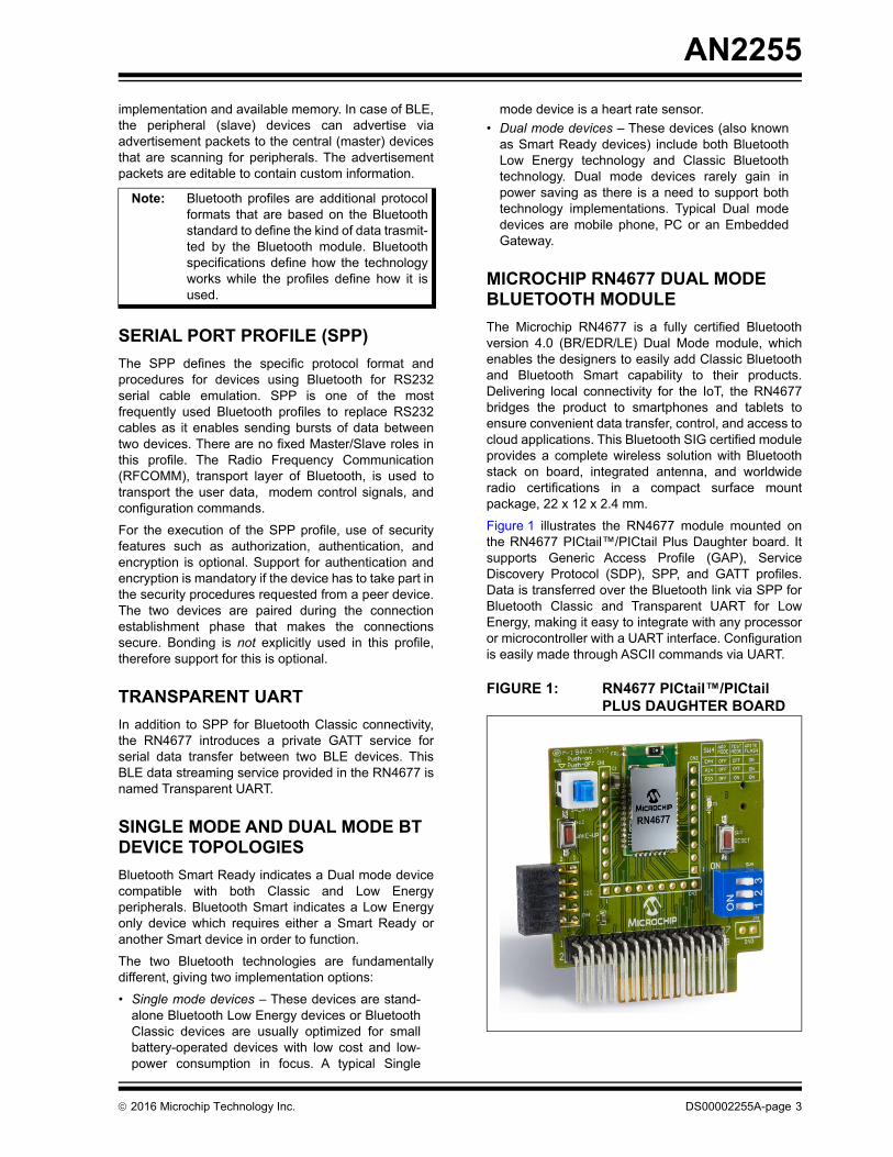
The Microchip RN4677 is a fully certified Bluetoothversion 4.0 (BR/EDR/LE) Dual Mode module, whichenables the designers to easily add Classic Bluetoothand Bluetooth Smart capability to their products.Delivering local connectivity for the IoT, the RN4677bridges the product to smartphones and tablets toensure convenient data transfer, control, and access tocloud applications. This Bluetooth SIG certified moduleprovides a complete wireless solution with Bluetoothstack on board, integrated antenna, and worldwideradio certifications in a compact surface mountpackage, 22 x 12 x 2.4 mm.
Figure 1 illustrates the RN4677 module mounted onthe RN4677 PICtail™/PICtail Plus Daughter board. Itsupports Generic Access Profile (GAP), ServiceDiscovery Protocol (SDP), SPP, and GATT profiles.Data is transferred over the Bluetooth link via SPP forBluetooth Classic and Transparent UART for LowEnergy, making it easy to integrate with any processoror microcontroller with a UART interface. Configurationis easily made through ASCII commands via UART.
FIGURE 1: RN4677 PICtail™/PICtail PLUS DAUGHTER BOARD
Note: Bluetooth profiles are additional protocolformats that are based on the Bluetoothstandard to define the kind of data trasmit-ted by the Bluetooth module. Bluetoothspecifications define how the technologyworks while the profiles define how it isused.
2016 Microchip Technology Inc. DS00002255A-page 3
AN2255
A Microcontroller Unit (MCU) or host processor sendscommands to configure module features, read status,and to manage Bluetooth data connections. The UARTTX and RX lines are required to communicate with themodule and transfer data through the Bluetooth SPP/Transparent UART connection. Connecting thehardware flow control lines, CTS and RTS, is highlyrecommended for applications that transmit acontinuous stream of data.
RN4677 MODULE AND PIC18 MCU INTERFACE FRAMEWORK
The demo application uses required ASCII commands,issued by the PIC18F87J11 microcontroller, toconfigure and setup the wireless BT nodes. User inputis given through the switches on the PIC18 ExplorerDevelopment board. Status messages are displayedon the LCD of PIC18 Explorer Development board.After successfully establishing a Bluetooth connectionbetween two nodes via a Gateway node, data in theform of strings/characters are transferred betweenthese nodes, showcasing the SPP profile in BTC modeand Transparent UART service in BLE mode, bothemulating the serial RS232 type of connection.
This application note provides the users with thefollowing functionalities:
• Framework for any user application platform using RN4677 Dual Mode Bluetooth module and PIC18F series of microcontrollers
• Specific interface between the RN4677 Bluetooth module and the PIC18F87J11 microcontroller
• Reference source code to manage BTC, BLE, and Dual mode connections of RN4677 module through PIC microcontroller
• Technique to enable switching between BTC and BLE modes and vice versa to implement a Gate-way using RN4677 Dual Mode module
• Demonstration of the Classic Bluetooth technology Serial Port Profile (SPP) and the Bluetooth Low Energy Private Service called Transparent UART for emulation of serial data connections
The hardware interface of the RN4677 module with anyof the PIC microcontrollers can be called a wirelessnode. In this demo, the interface between the RN4677PICtail/PICtail Plus Daughter board and the PIC18
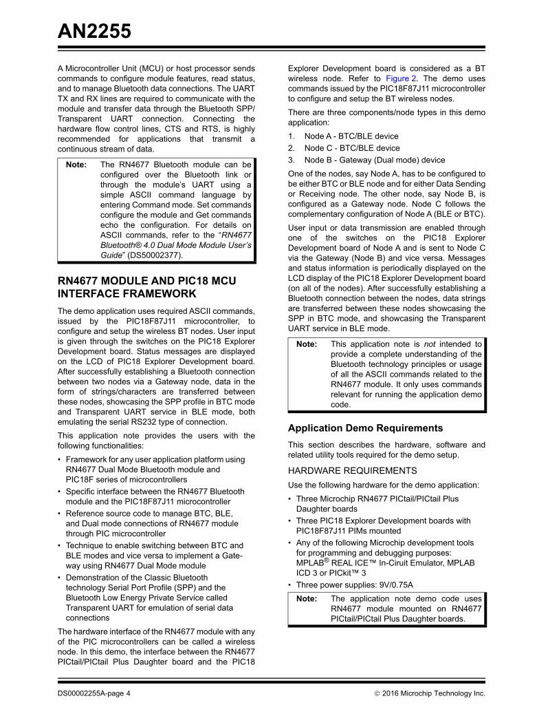
Explorer Development board is considered as a BTwireless node. Refer to Figure 2. The demo usescommands issued by the PIC18F87J11 microcontrollerto configure and setup the BT wireless nodes.
There are three components/node types in this demoapplication:
1. Node A - BTC/BLE device
2. Node C - BTC/BLE device
3. Node B - Gateway (Dual mode) device
One of the nodes, say Node A, has to be configured tobe either BTC or BLE node and for either Data Sendingor Receiving node. The other node, say Node B, isconfigured as a Gateway node. Node C follows thecomplementary configuration of Node A (BLE or BTC).
User input or data transmission are enabled throughone of the switches on the PIC18 ExplorerDevelopment board of Node A and is sent to Node Cvia the Gateway (Node B) and vice versa. Messagesand status information is periodically displayed on theLCD display of the PIC18 Explorer Development board(on all of the nodes). After successfully establishing aBluetooth connection between the nodes, data stringsare transferred between these nodes showcasing theSPP in BTC mode, and showcasing the TransparentUART service in BLE mode.
Application Demo Requirements
This section describes the hardware, software andrelated utility tools required for the demo setup.
HARDWARE REQUIREMENTS
Use the following hardware for the demo application:
• Three Microchip RN4677 PICtail/PICtail Plus Daughter boards
• Three PIC18 Explorer Development boards with PIC18F87J11 PIMs mounted
• Any of the following Microchip development tools for programming and debugging purposes: MPLAB® REAL ICE™ In-Ciruit Emulator, MPLAB ICD 3 or PICkit™ 3
• Three power supplies: 9V/0.75A
Note: The RN4677 Bluetooth module can beconfigured over the Bluetooth link orthrough the module’s UART using asimple ASCII command language byentering Command mode. Set commandsconfigure the module and Get commandsecho the configuration. For details onASCII commands, refer to the “RN4677Bluetooth® 4.0 Dual Mode Module User’sGuide” (DS50002377).
Note: This application note is not intended toprovide a complete understanding of theBluetooth technology principles or usageof all the ASCII commands related to theRN4677 module. It only uses commandsrelevant for running the application democode.
Note: The application note demo code usesRN4677 module mounted on RN4677PICtail/PICtail Plus Daughter boards.
DS00002255A-page 4 2016 Microchip Technology Inc.
AN2255
SOFTWARE/UTILITY REQUIREMENTS
This demo application intends to showcase gatewaycommunication between two Classic or Low EnergyBluetooth wireless nodes using the Dual mode RN4677modules. The application demo source code related tothis application note is available as MPLAB Xworkspace project file and is available for downloadfrom the Microchip web site at www.microchip.com.The code is compiled using the Microchip XC8compiler v1.34 and MPLAB X IDE v3.05.
Demo source code is available for download from theDocumentation and Software link section of theRN4677 product page at www.microchip.com/RN4677.
Use the precompiled BTC_BLE_TLNode.X.production.hex file of the demo orcompile the BTC_BLE_TL Node project code ifrequired. Ensure the compilation is successful. Foradditional information on the source code, related fileswith description, and call graph, refer to Appendix A:"Source Code". From MPLAB X, user can generatecall graphs related to specific functions of the democode.
FIGURE 2: APPLICATION DIAGRAM OF COMMUNICATION VIA GATEWAY USING BT NODES
Note: The RN4677 modules must have firmwareversion 1.00 and above for the demo codeto work. To know the details of the firm-ware version, refer to the product pagefrom the Microchip website.
PIC 8-bit MCU RN4677Module
PIC® 8-bit MCU RN4677Module
Gateway Node
BTC Node (BLE Node)
BLE Node (BTC Node)
Node A
Node B
Node C
PIC 8-bit MCU RN4677Module
2016 Microchip Technology Inc. DS00002255A-page 5
AN2255
HARDWARE DEMO SETUP
This RN4677 based communication requires threewireless nodes. The demo setup consists of threePIC18 Explorer Development boards interfaced withthree identical RN4677 PICtail/PICtail Plus Daughterboards as shown in Figure 2. Thus, the three identicalRN4677 Dual Mode module-based wireless nodes areused for this application demonstration. For moreinformation on the RN4677 module, refer to the“RN4677 PICtail™/PICtail Plus Board User’s Guide”(DS50002388).
PIC18 Explorer Development Board and RN4677 Module Connections
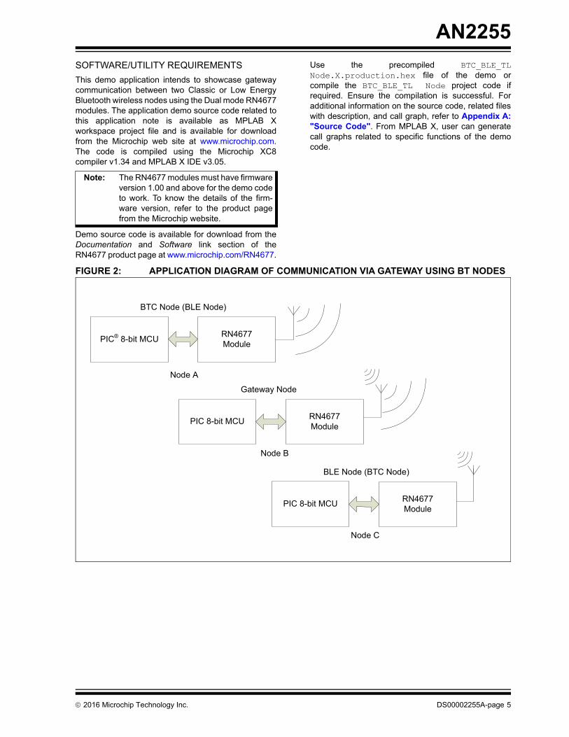
The RN4677 PICtail/PICtail Plus Daughter board isinserted into the connector socket of the PIC18Explorer Development board. This connection supplies3.3V power, 2-wire or 4-wire UART, wake-up,SW_BTN, and Reset functions to the RN4677 modulefrom the microcontroller. Table 1 shows the connectiondetails of the RN4677 PICtail/PICtail Plus Daughterboard to the PIC18 Explorer Development board.
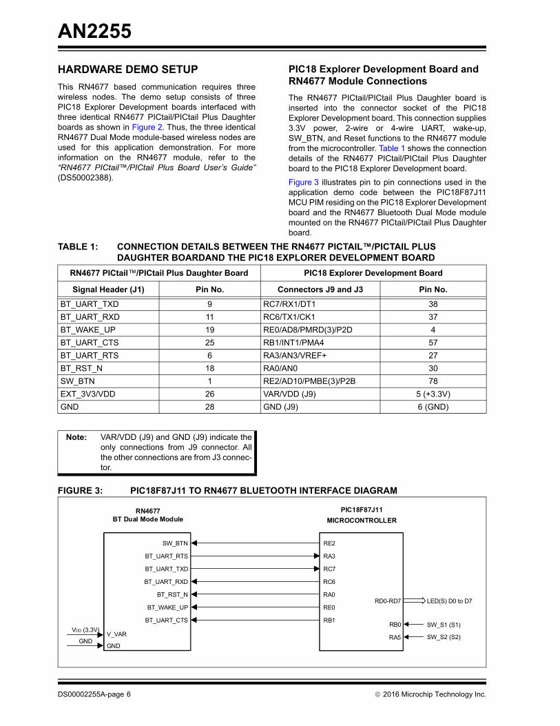
Figure 3 illustrates pin to pin connections used in theapplication demo code between the PIC18F87J11MCU PIM residing on the PIC18 Explorer Developmentboard and the RN4677 Bluetooth Dual Mode modulemounted on the RN4677 PICtail/PICtail Plus Daughterboard.
FIGURE 3: PIC18F87J11 TO RN4677 BLUETOOTH INTERFACE DIAGRAM
TABLE 1: CONNECTION DETAILS BETWEEN THE RN4677 PICTAIL™/PICTAIL PLUS DAUGHTER BOARDAND THE PIC18 EXPLORER DEVELOPMENT BOARD
RN4677 PICtail™/PICtail Plus Daughter Board PIC18 Explorer Development Board
Signal Header (J1) Pin No. Connectors J9 and J3 Pin No.
BT_UART_TXD 9 RC7/RX1/DT1 38
BT_UART_RXD 11 RC6/TX1/CK1 37
BT_WAKE_UP 19 RE0/AD8/PMRD(3)/P2D 4
BT_UART_CTS 25 RB1/INT1/PMA4 57
BT_UART_RTS 6 RA3/AN3/VREF+ 27
BT_RST_N 18 RA0/AN0 30
SW_BTN 1 RE2/AD10/PMBE(3)/P2B 78
EXT_3V3/VDD 26 VAR/VDD (J9) 5 (+3.3V)
GND 28 GND (J9) 6 (GND)
Note: VAR/VDD (J9) and GND (J9) indicate theonly connections from J9 connector. Allthe other connections are from J3 connec-tor.
PIC18F87J11MICROCONTROLLER
RN4677BT Dual Mode Module
VDD (3.3V)
GND
BT_UART_RTS
BT_UART_TXD
BT_UART_RXD
BT_RST_N
BT_WAKE_UP
BT_UART_CTS
RD0-RD7
RB0
RA5
LED(S) D0 to D7
SW_S1 (S1)
SW_S2 (S2)
SW_BTN
V_VAR
GND
RA3
RC7
RC6
RA0
RE0
RB1
RE2
DS00002255A-page 6 2016 Microchip Technology Inc.
AN2255
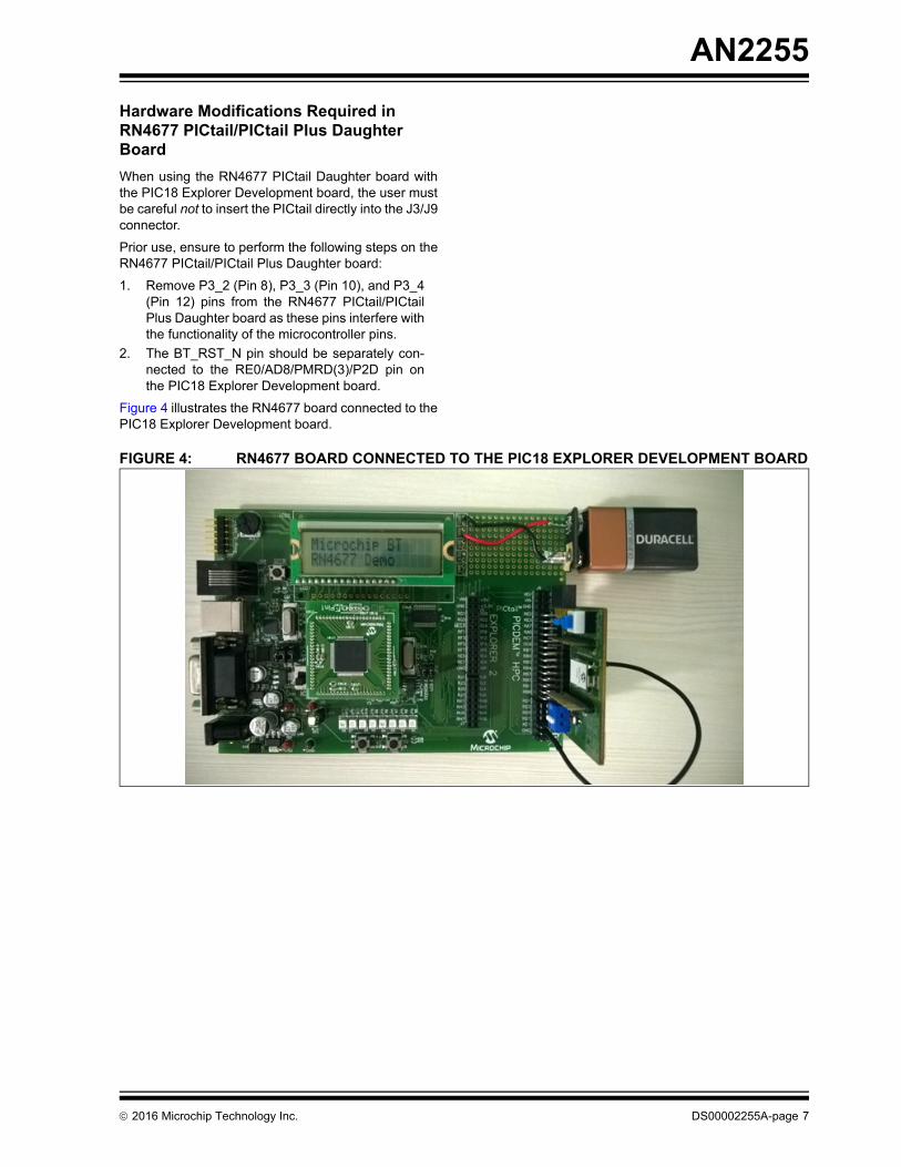
Hardware Modifications Required in RN4677 PICtail/PICtail Plus Daughter Board
When using the RN4677 PICtail Daughter board withthe PIC18 Explorer Development board, the user mustbe careful not to insert the PICtail directly into the J3/J9connector.
Prior use, ensure to perform the following steps on theRN4677 PICtail/PICtail Plus Daughter board:
1. Remove P3_2 (Pin 8), P3_3 (Pin 10), and P3_4(Pin 12) pins from the RN4677 PICtail/PICtailPlus Daughter board as these pins interfere withthe functionality of the microcontroller pins.
2. The BT_RST_N pin should be separately con-nected to the RE0/AD8/PMRD(3)/P2D pin onthe PIC18 Explorer Development board.
Figure 4 illustrates the RN4677 board connected to thePIC18 Explorer Development board.
FIGURE 4: RN4677 BOARD CONNECTED TO THE PIC18 EXPLORER DEVELOPMENT BOARD
2016 Microchip Technology Inc. DS00002255A-page 7
AN2255
GETTING STARTED
Setting Up the Bluetooth Nodes
To setup a wireless BT node, perform the followinginstructions:
1. Insert the RN4677 PICtail/PICtail Plus Daughterboard into the connector socket of the PIC18Explorer Development board.
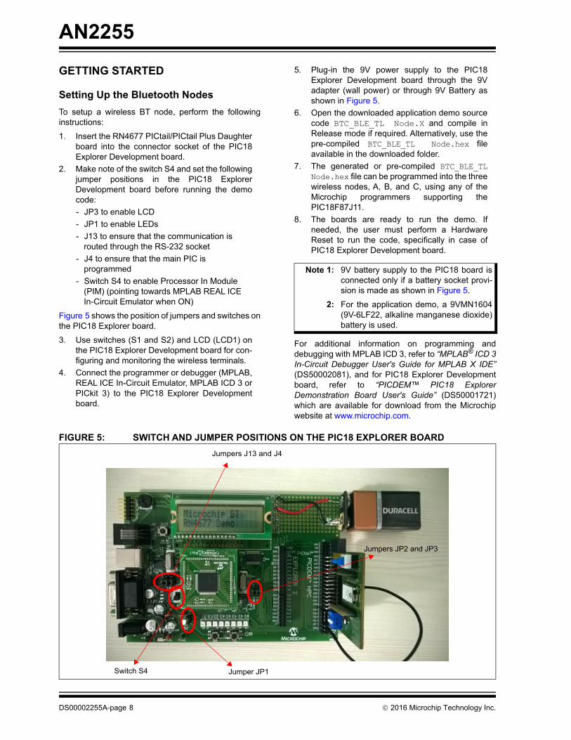
2. Make note of the switch S4 and set the followingjumper positions in the PIC18 ExplorerDevelopment board before running the democode:
- JP3 to enable LCD
- JP1 to enable LEDs
- J13 to ensure that the communication is routed through the RS-232 socket
- J4 to ensure that the main PIC is programmed
- Switch S4 to enable Processor In Module (PIM) (pointing towards MPLAB REAL ICE In-Circuit Emulator when ON)
Figure 5 shows the position of jumpers and switches onthe PIC18 Explorer board.
3. Use switches (S1 and S2) and LCD (LCD1) onthe PIC18 Explorer Development board for con-figuring and monitoring the wireless terminals.
4. Connect the programmer or debugger (MPLAB,REAL ICE In-Circuit Emulator, MPLAB ICD 3 orPICkit 3) to the PIC18 Explorer Developmentboard.
5. Plug-in the 9V power supply to the PIC18Explorer Development board through the 9Vadapter (wall power) or through 9V Battery asshown in Figure 5.
6. Open the downloaded application demo sourcecode BTC_BLE_TL Node.X and compile inRelease mode if required. Alternatively, use thepre-compiled BTC_BLE_TL Node.hex fileavailable in the downloaded folder.
7. The generated or pre-compiled BTC_BLE_TLNode.hex file can be programmed into the threewireless nodes, A, B, and C, using any of theMicrochip programmers supporting thePIC18F87J11.
8. The boards are ready to run the demo. Ifneeded, the user must perform a HardwareReset to run the code, specifically in case ofPIC18 Explorer Development board.
For additional information on programming anddebugging with MPLAB ICD 3, refer to “MPLAB® ICD 3In-Circuit Debugger User's Guide for MPLAB X IDE”(DS50002081), and for PIC18 Explorer Developmentboard, refer to “PICDEM™ PIC18 ExplorerDemonstration Board User's Guide” (DS50001721)which are available for download from the Microchipwebsite at www.microchip.com.
FIGURE 5: SWITCH AND JUMPER POSITIONS ON THE PIC18 EXPLORER BOARD
Note 1: 9V battery supply to the PIC18 board isconnected only if a battery socket provi-sion is made as shown in Figure 5.
2: For the application demo, a 9VMN1604(9V-6LF22, alkaline manganese dioxide)battery is used.
Jumpers J13 and J4
Jumpers JP2 and JP3
Switch S4 Jumper JP1
DS00002255A-page 8 2016 Microchip Technology Inc.
AN2255
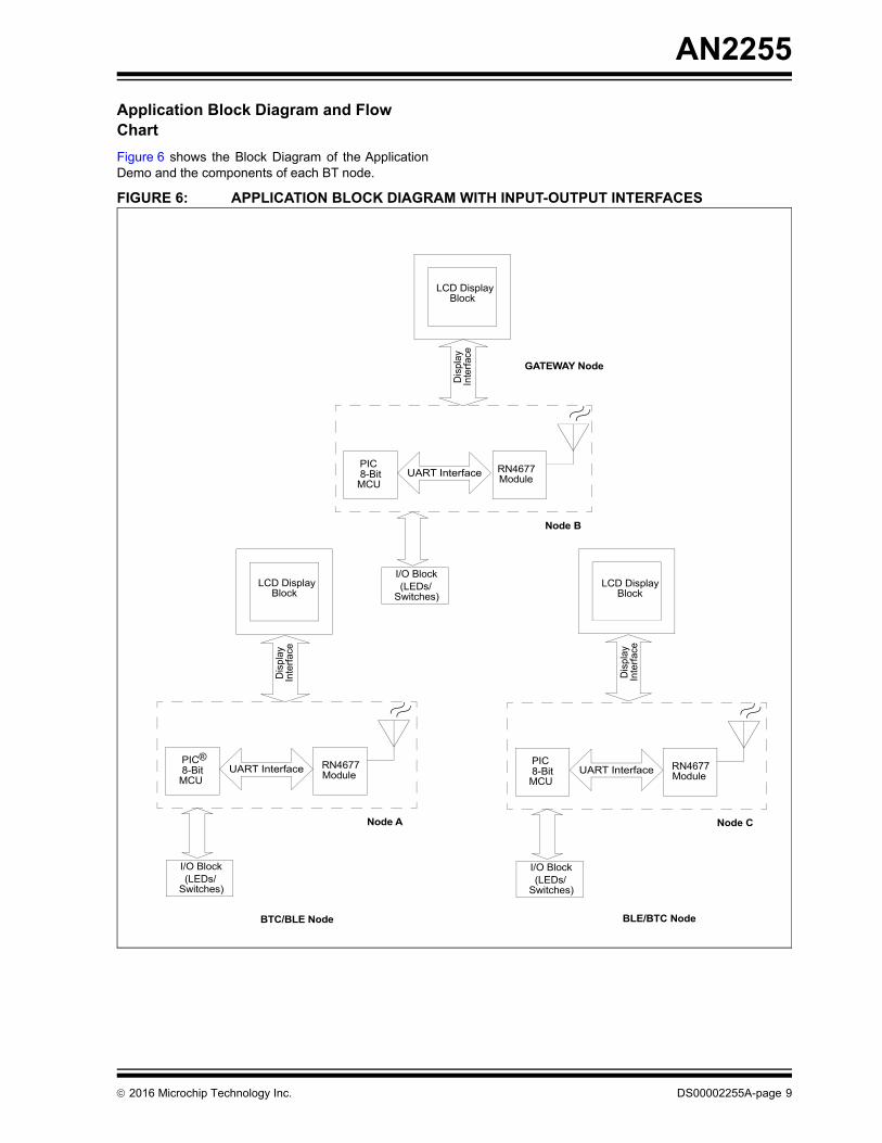
Application Block Diagram and Flow Chart
Figure 6 shows the Block Diagram of the ApplicationDemo and the components of each BT node.
FIGURE 6: APPLICATION BLOCK DIAGRAM WITH INPUT-OUTPUT INTERFACES
Node A
PIC® 8-Bit
MCU
RN4677Module
UART Interface
LCD Display Block
Dis
play
LCD Display Block
I/O Block(LEDs/
Switches)
Inte
rfac
e
Dis
play
Inte
rfac
e
Node B
PIC 8-Bit
MCU
RN4677Module
UART Interface
LCD Display Block
Dis
play
I/O Block(LEDs/
Switches)
Inte
rfac
e
Node C
PIC 8-Bit
MCU
RN4677Module
UART Interface
I/O Block(LEDs/
Switches)
GATEWAY Node
BTC/BLE Node BLE/BTC Node
2016 Microchip Technology Inc. DS00002255A-page 9
AN2255
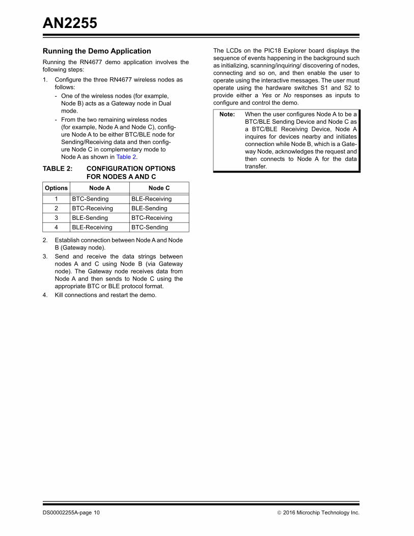
Running the Demo Application
Running the RN4677 demo application involves thefollowing steps:
1. Configure the three RN4677 wireless nodes asfollows:
- One of the wireless nodes (for example, Node B) acts as a Gateway node in Dual mode.
- From the two remaining wireless nodes (for example, Node A and Node C), config-ure Node A to be either BTC/BLE node for Sending/Receiving data and then config-ure Node C in complementary mode to Node A as shown in Table 2.
2. Establish connection between Node A and NodeB (Gateway node).
3. Send and receive the data strings betweennodes A and C using Node B (via Gatewaynode). The Gateway node receives data fromNode A and then sends to Node C using theappropriate BTC or BLE protocol format.
4. Kill connections and restart the demo.
The LCDs on the PIC18 Explorer board displays thesequence of events happening in the background suchas initializing, scanning/inquiring/ discovering of nodes,connecting and so on, and then enable the user tooperate using the interactive messages. The user mustoperate using the hardware switches S1 and S2 toprovide either a Yes or No responses as inputs toconfigure and control the demo.
TABLE 2: CONFIGURATION OPTIONS FOR NODES A AND C
Options Node A Node C
1 BTC-Sending BLE-Receiving
2 BTC-Receiving BLE-Sending
3 BLE-Sending BTC-Receiving
4 BLE-Receiving BTC-Sending
Note: When the user configures Node A to be aBTC/BLE Sending Device and Node C asa BTC/BLE Receiving Device, Node Ainquires for devices nearby and initiatesconnection while Node B, which is a Gate-way Node, acknowledges the request andthen connects to Node A for the datatransfer.
DS00002255A-page 10 2016 Microchip Technology Inc.
AN2255
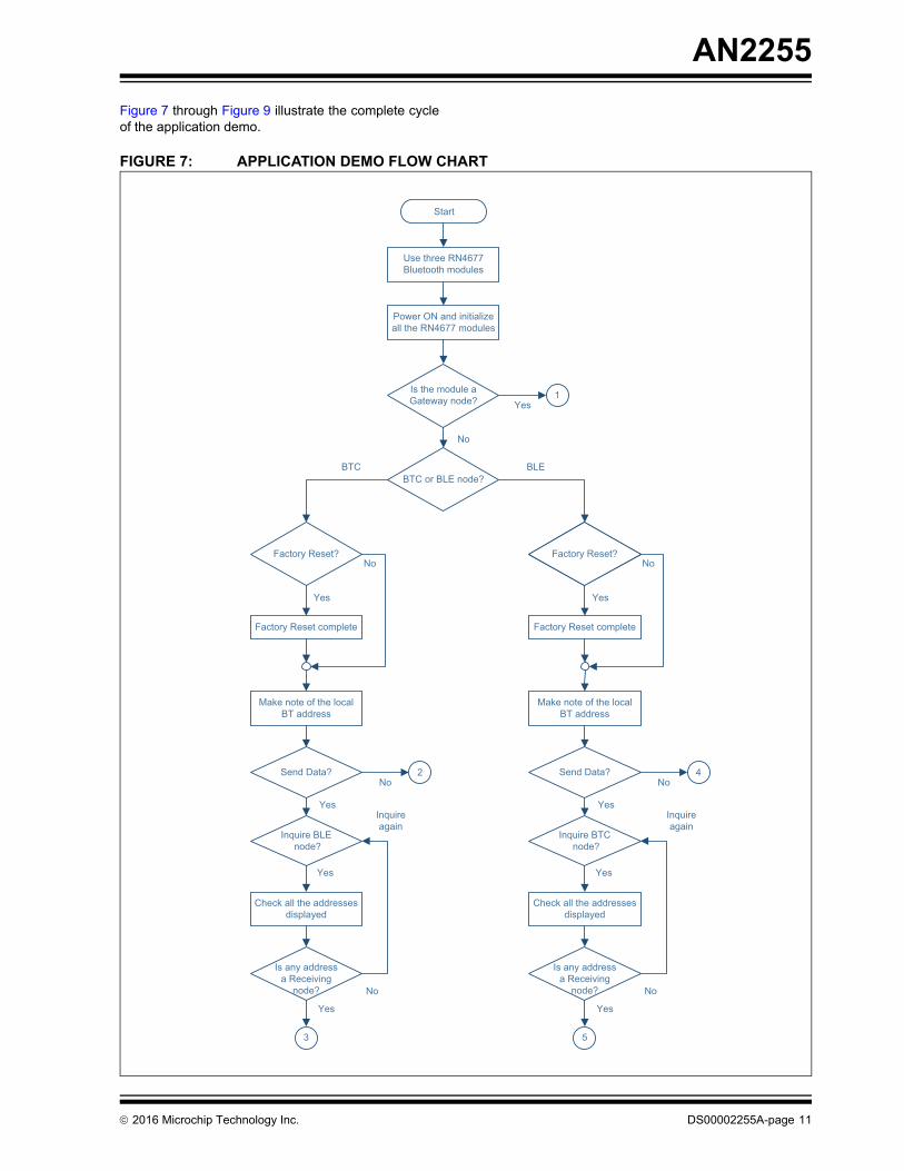
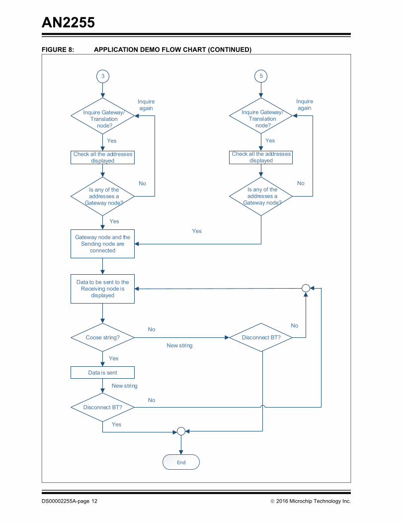
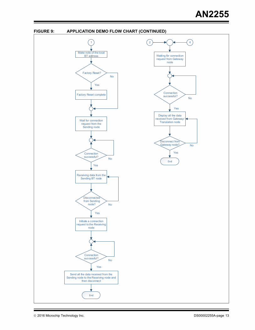
Figure 7 through Figure 9 illustrate the complete cycleof the application demo.
FIGURE 7: APPLICATION DEMO FLOW CHART
Use three RN4677Bluetooth modules
Power ON and initializeall the RN4677 modules
BTC
Yes1Is the module a
Gateway node?
No
BTC or BLE node?
Factory Reset?
BLE
Factory Reset?
Factory Reset complete
Make note of the localBT address
Send Data?
No
Yes
Inquire BLEnode?
Yes
No2
Check all the addressesdisplayed
Yes
Is any addressa Receiving
node? No
3
Yes
Factory Reset?
Factory Reset complete
Make note of the localBT address
Send Data?
No
Yes
Inquire BTCnode?
Yes
No4
Check all the addressesdisplayed
Yes
Is any addressa Receiving
node? No
5
Yes
Inquireagain
Inquireagain
Start
2016 Microchip Technology Inc. DS00002255A-page 11
AN2255
FIGURE 8: APPLICATION DEMO FLOW CHART (CONTINUED)
Gateway node and the Sending node are
connected
Yes
Yes
3 5
Data to be sent to the Receiving node is
displayed
Coose string?
Data is sent
Disconnect BT?
End
Inquire Gateway/Translation
node?
Check all the addresses displayed
Yes
Inquire again
Is any of the addresses a
Gateway node?
No
Inquire Gateway/Translation
node?
Check all the addresses displayed
Yes
Inquire again
Is any of the addresses a
Gateway node?
No
Yes
Disconnect BT?No
New string
No
No
New string
Yes
DS00002255A-page 12 2016 Microchip Technology Inc.
AN2255
FIGURE 9: APPLICATION DEMO FLOW CHART (CONTINUED)
Factory Reset complete
Yes
Yes
1
Wait for connection request from the Sending node
Connection successful?
Receiving data from the Sending BT node
Disconnected from Sending
node?
End
Make note of the local BT address
Factory Reset?No
Waiting for connection request from Gateway
node
Connection successful?
No
Yes
No
No
No
Initiate a connection request to the Receiving
node
Connection successful? No
Yes
Yes
Send all the data received from the Sending node to the Receiving node and
then disconnect
2 4
Display all the data received from Gateway/
Translation node
Yes
Disconnect from Gateway node?
End
Yes
2016 Microchip Technology Inc. DS00002255A-page 13
AN2255
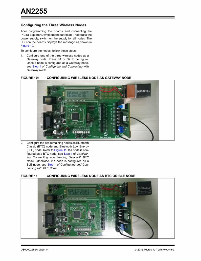
Configuring the Three Wireless Nodes
After programming the boards and connecting thePIC18 Explorer Development boards (BT nodes) to thepower supply, switch on the supply for all nodes. TheLCD on the boards displays the message as shown inFigure 10.
To configure the nodes, follow these steps:
1. Configure one of the three wireless nodes as aGateway node. Press S1 or S2 to configure.Once a node is configured as a Gateway node,see Step 1 of Configuring and Connecting withGateway Node.
FIGURE 10: CONFIGURING WIRELESS NODE AS GATEWAY NODE
2. Configure the two remaining nodes as BluetoothClassic (BTC) node and Bluetooth Low Energy(BLE) node. Refer to Figure 11. If a node is con-figured as a BTC node, see Step 1 of Configur-ing, Connecting, and Sending Data with BTCNode. Otherwise, if a node is configured as aBLE node, see Step 1 of Configuring and Con-necting with BLE Node.
FIGURE 11: CONFIGURING WIRELESS NODE AS BTC OR BLE NODE
DS00002255A-page 14 2016 Microchip Technology Inc.
AN2255
Configuring, Connecting, and Sending Data with BTC Node
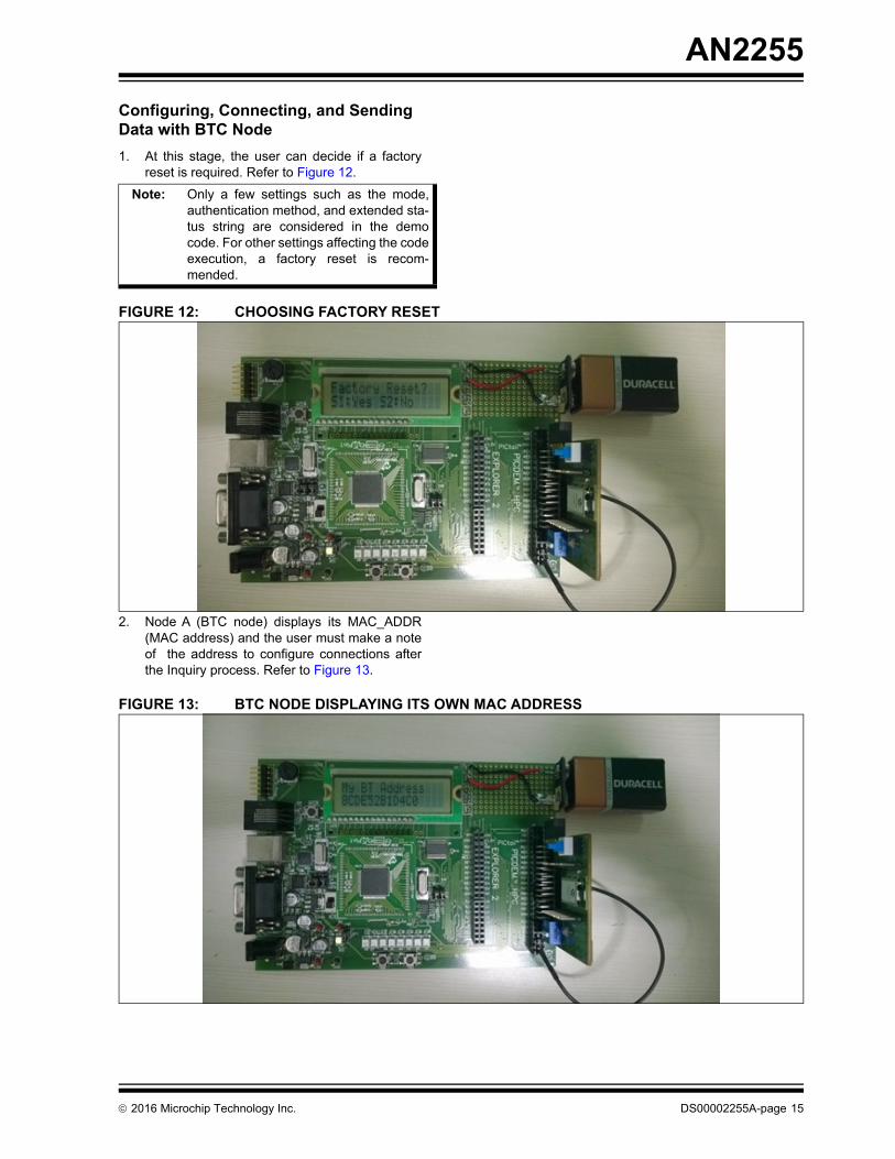
1. At this stage, the user can decide if a factoryreset is required. Refer to Figure 12.
FIGURE 12: CHOOSING FACTORY RESET
2. Node A (BTC node) displays its MAC_ADDR(MAC address) and the user must make a noteof the address to configure connections afterthe Inquiry process. Refer to Figure 13.
FIGURE 13: BTC NODE DISPLAYING ITS OWN MAC ADDRESS
Note: Only a few settings such as the mode,authentication method, and extended sta-tus string are considered in the democode. For other settings affecting the codeexecution, a factory reset is recom-mended.
2016 Microchip Technology Inc. DS00002255A-page 15
AN2255
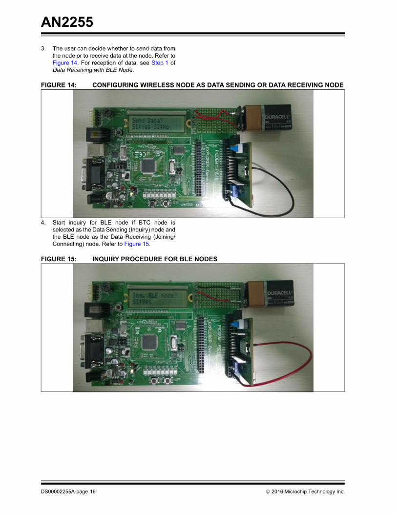
3. The user can decide whether to send data fromthe node or to receive data at the node. Refer toFigure 14. For reception of data, see Step 1 ofData Receiving with BLE Node.
FIGURE 14: CONFIGURING WIRELESS NODE AS DATA SENDING OR DATA RECEIVING NODE
4. Start inquiry for BLE node if BTC node isselected as the Data Sending (Inquiry) node andthe BLE node as the Data Receiving (Joining/Connecting) node. Refer to Figure 15.
FIGURE 15: INQUIRY PROCEDURE FOR BLE NODES
DS00002255A-page 16 2016 Microchip Technology Inc.
AN2255
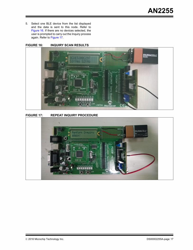
5. Select one BLE device from the list displayedand the data is sent to this node. Refer toFigure 16. If there are no devices selected, theuser is prompted to carry out the Inquiry processagain. Refer to Figure 17.
FIGURE 16: INQUIRY SCAN RESULTS
FIGURE 17: REPEAT INQUIRY PROCEDURE
2016 Microchip Technology Inc. DS00002255A-page 17
AN2255
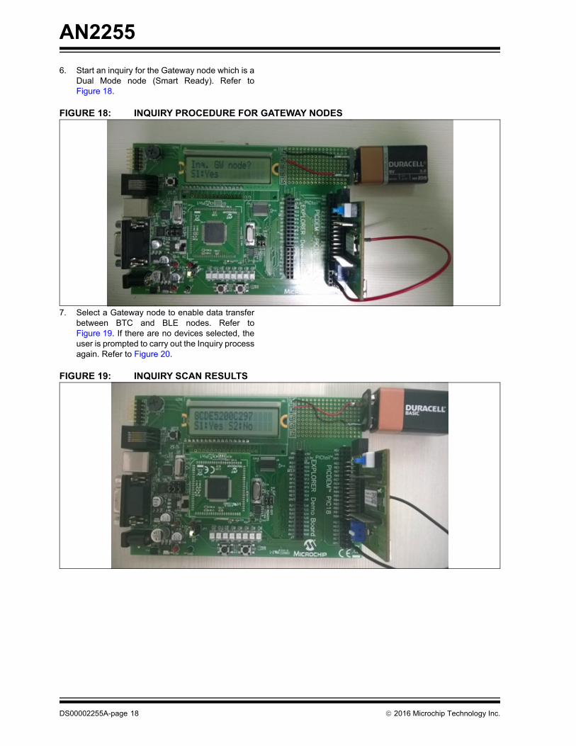
6. Start an inquiry for the Gateway node which is aDual Mode node (Smart Ready). Refer toFigure 18.
FIGURE 18: INQUIRY PROCEDURE FOR GATEWAY NODES
7. Select a Gateway node to enable data transferbetween BTC and BLE nodes. Refer toFigure 19. If there are no devices selected, theuser is prompted to carry out the Inquiry processagain. Refer to Figure 20.
FIGURE 19: INQUIRY SCAN RESULTS
DS00002255A-page 18 2016 Microchip Technology Inc.
AN2255
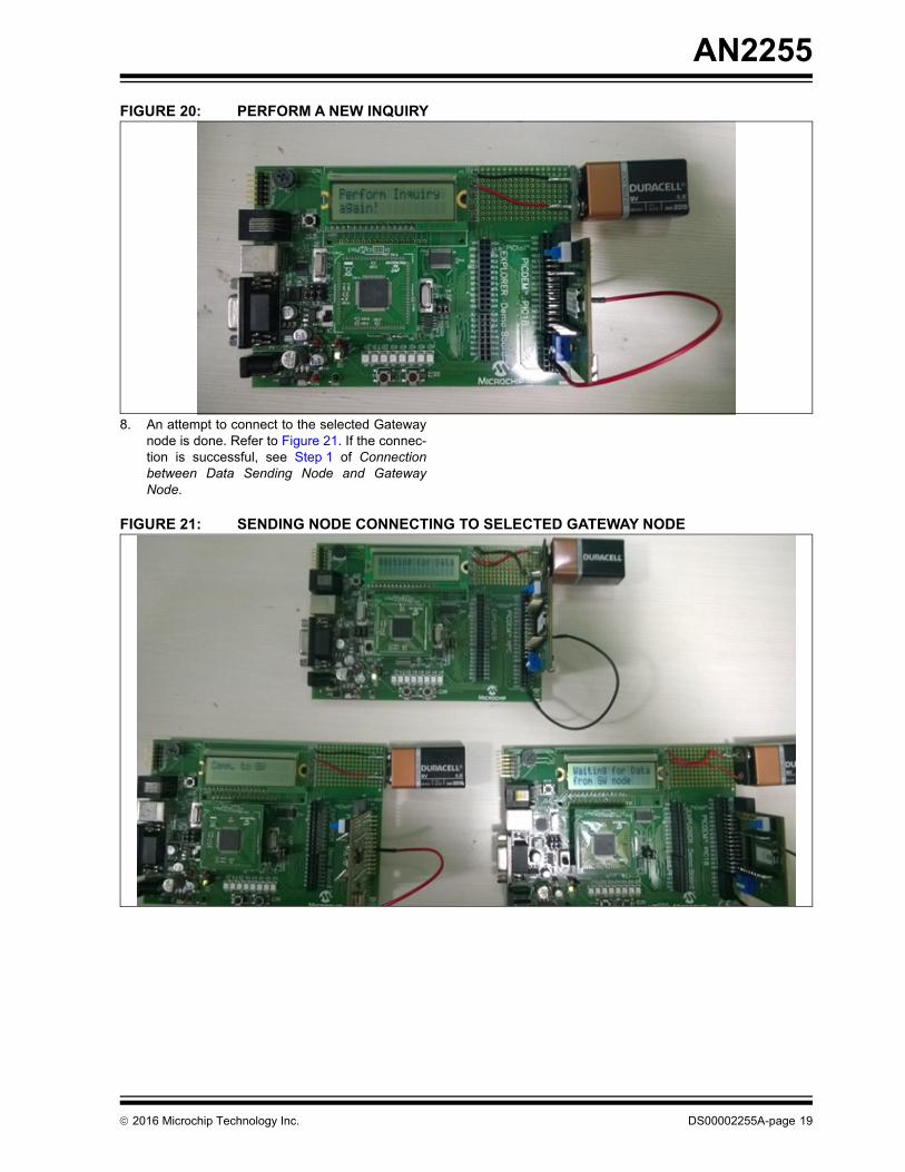
FIGURE 20: PERFORM A NEW INQUIRY
8. An attempt to connect to the selected Gatewaynode is done. Refer to Figure 21. If the connec-tion is successful, see Step 1 of Connectionbetween Data Sending Node and GatewayNode.
FIGURE 21: SENDING NODE CONNECTING TO SELECTED GATEWAY NODE
2016 Microchip Technology Inc. DS00002255A-page 19
AN2255
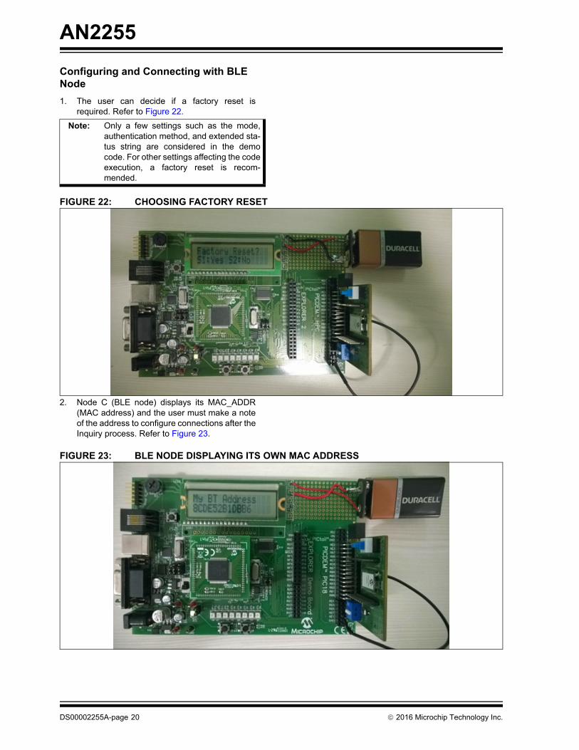
Configuring and Connecting with BLE Node
1. The user can decide if a factory reset isrequired. Refer to Figure 22.
FIGURE 22: CHOOSING FACTORY RESET
2. Node C (BLE node) displays its MAC_ADDR(MAC address) and the user must make a noteof the address to configure connections after theInquiry process. Refer to Figure 23.
FIGURE 23: BLE NODE DISPLAYING ITS OWN MAC ADDRESS
Note: Only a few settings such as the mode,authentication method, and extended sta-tus string are considered in the democode. For other settings affecting the codeexecution, a factory reset is recom-mended.
DS00002255A-page 20 2016 Microchip Technology Inc.
AN2255
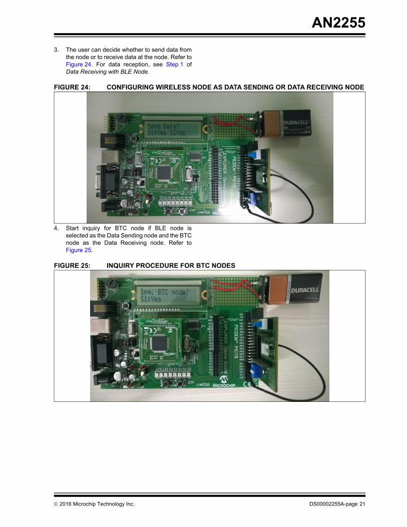
3. The user can decide whether to send data fromthe node or to receive data at the node. Refer toFigure 24. For data reception, see Step 1 ofData Receiving with BLE Node.
FIGURE 24: CONFIGURING WIRELESS NODE AS DATA SENDING OR DATA RECEIVING NODE
4. Start inquiry for BTC node if BLE node isselected as the Data Sending node and the BTCnode as the Data Receiving node. Refer toFigure 25.
FIGURE 25: INQUIRY PROCEDURE FOR BTC NODES
2016 Microchip Technology Inc. DS00002255A-page 21
AN2255
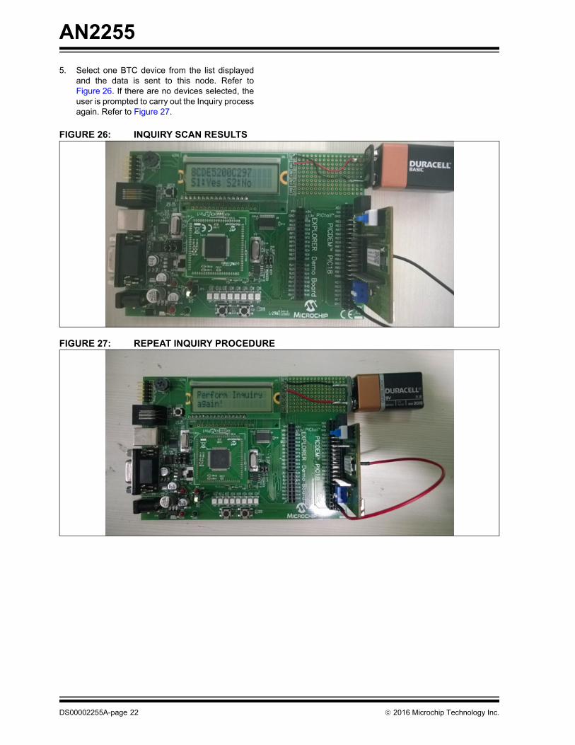
5. Select one BTC device from the list displayedand the data is sent to this node. Refer toFigure 26. If there are no devices selected, theuser is prompted to carry out the Inquiry processagain. Refer to Figure 27.
FIGURE 26: INQUIRY SCAN RESULTS
FIGURE 27: REPEAT INQUIRY PROCEDURE
DS00002255A-page 22 2016 Microchip Technology Inc.
AN2255
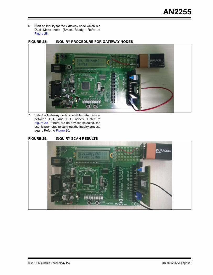
6. Start an inquiry for the Gateway node which is aDual Mode node (Smart Ready). Refer toFigure 28.
FIGURE 28: INQUIRY PROCEDURE FOR GATEWAY NODES
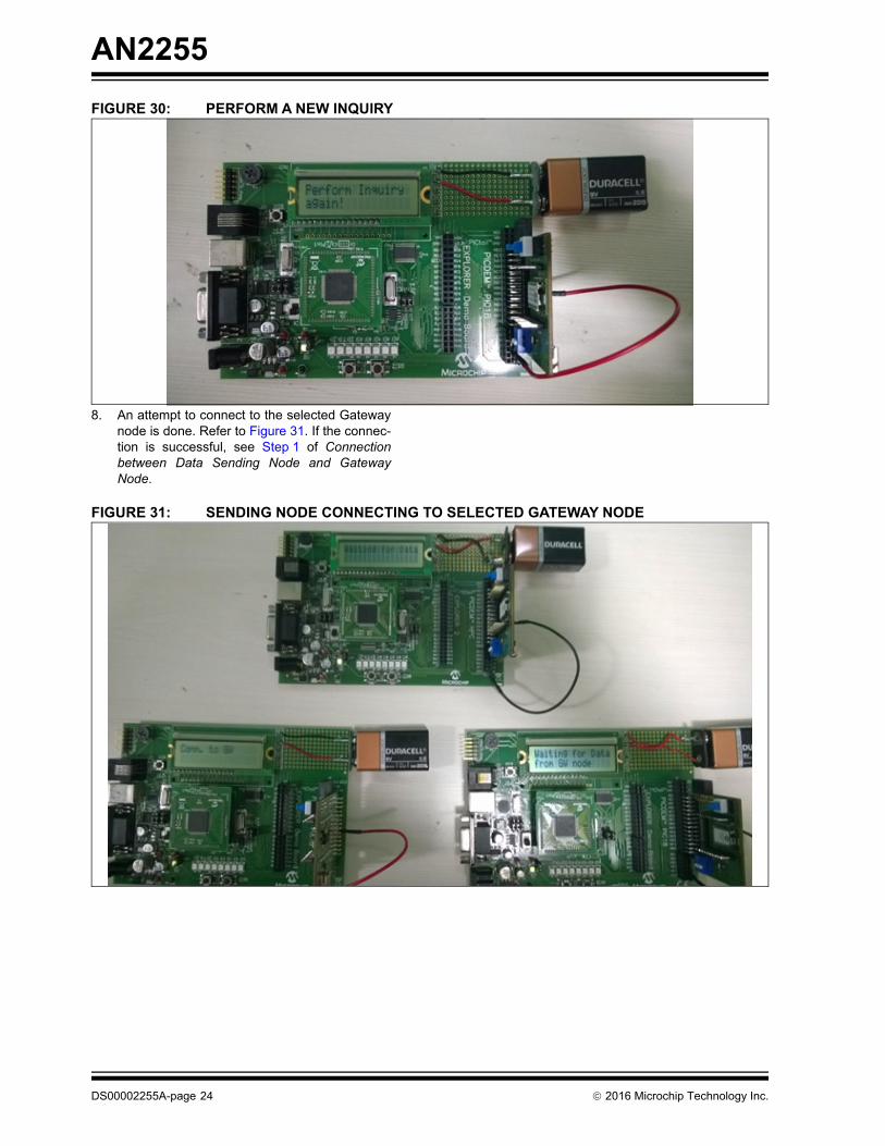
7. Select a Gateway node to enable data transferbetween BTC and BLE nodes. Refer toFigure 29. If there are no devices selected, theuser is prompted to carry out the Inquiry processagain. Refer to Figure 30.
FIGURE 29: INQUIRY SCAN RESULTS
2016 Microchip Technology Inc. DS00002255A-page 23
AN2255
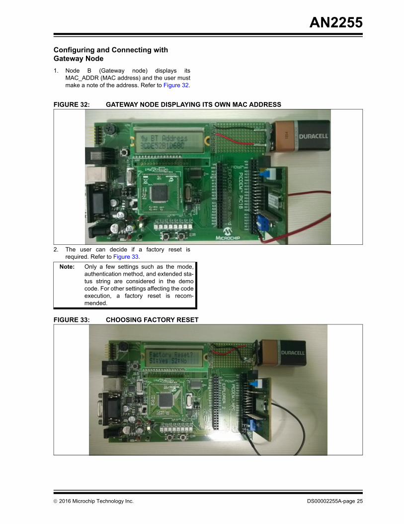
FIGURE 30: PERFORM A NEW INQUIRY
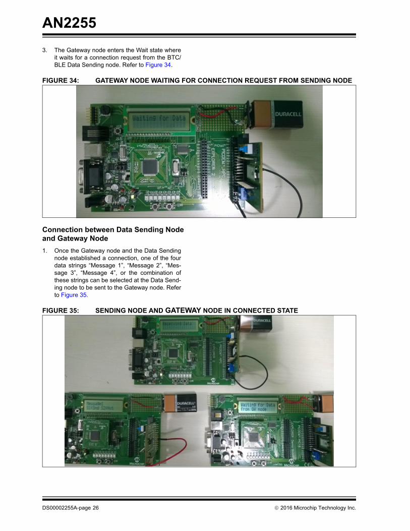
8. An attempt to connect to the selected Gatewaynode is done. Refer to Figure 31. If the connec-tion is successful, see Step 1 of Connectionbetween Data Sending Node and GatewayNode.
FIGURE 31: SENDING NODE CONNECTING TO SELECTED GATEWAY NODE
DS00002255A-page 24 2016 Microchip Technology Inc.
AN2255
Configuring and Connecting with Gateway Node
1. Node B (Gateway node) displays itsMAC_ADDR (MAC address) and the user mustmake a note of the address. Refer to Figure 32.
FIGURE 32: GATEWAY NODE DISPLAYING ITS OWN MAC ADDRESS
2. The user can decide if a factory reset isrequired. Refer to Figure 33.
FIGURE 33: CHOOSING FACTORY RESET
Note: Only a few settings such as the mode,authentication method, and extended sta-tus string are considered in the democode. For other settings affecting the codeexecution, a factory reset is recom-mended.
2016 Microchip Technology Inc. DS00002255A-page 25
AN2255
3. The Gateway node enters the Wait state whereit waits for a connection request from the BTC/BLE Data Sending node. Refer to Figure 34.
FIGURE 34: GATEWAY NODE WAITING FOR CONNECTION REQUEST FROM SENDING NODE
Connection between Data Sending Node and Gateway Node
1. Once the Gateway node and the Data Sendingnode established a connection, one of the fourdata strings “Message 1”, “Message 2”, “Mes-sage 3”, “Message 4”, or the combination ofthese strings can be selected at the Data Send-ing node to be sent to the Gateway node. Referto Figure 35.
FIGURE 35: SENDING NODE AND GATEWAY NODE IN CONNECTED STATE
DS00002255A-page 26 2016 Microchip Technology Inc.
AN2255
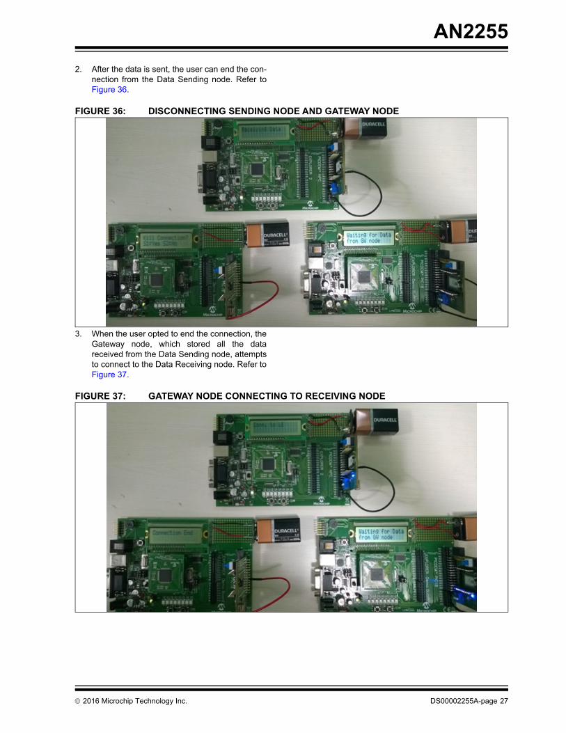
2. After the data is sent, the user can end the con-nection from the Data Sending node. Refer toFigure 36.
FIGURE 36: DISCONNECTING SENDING NODE AND GATEWAY NODE
3. When the user opted to end the connection, theGateway node, which stored all the datareceived from the Data Sending node, attemptsto connect to the Data Receiving node. Refer toFigure 37.
FIGURE 37: GATEWAY NODE CONNECTING TO RECEIVING NODE
2016 Microchip Technology Inc. DS00002255A-page 27
AN2255
Connection between Gateway Node and Data Receiving Node
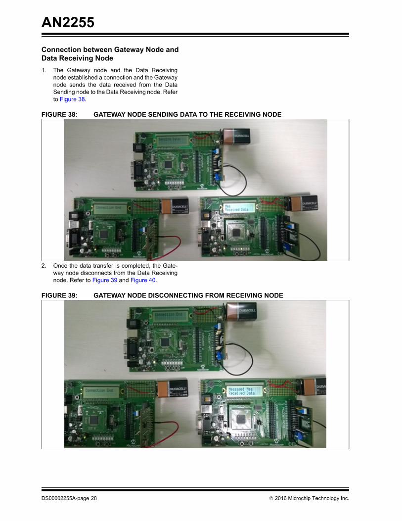
1. The Gateway node and the Data Receivingnode established a connection and the Gatewaynode sends the data received from the DataSending node to the Data Receiving node. Referto Figure 38.
FIGURE 38: GATEWAY NODE SENDING DATA TO THE RECEIVING NODE
2. Once the data transfer is completed, the Gate-way node disconnects from the Data Receivingnode. Refer to Figure 39 and Figure 40.
FIGURE 39: GATEWAY NODE DISCONNECTING FROM RECEIVING NODE
DS00002255A-page 28 2016 Microchip Technology Inc.
AN2255
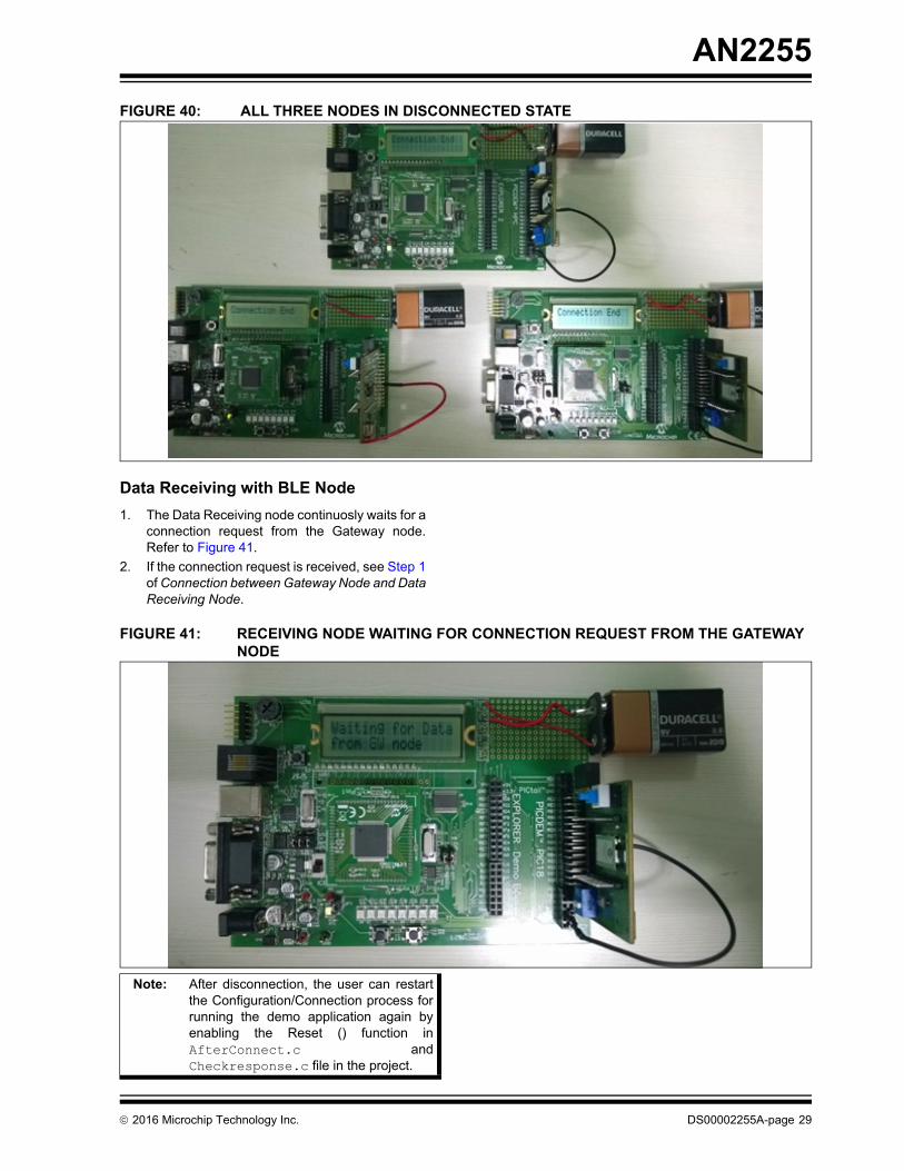
FIGURE 40: ALL THREE NODES IN DISCONNECTED STATE
Data Receiving with BLE Node
1. The Data Receiving node continuosly waits for aconnection request from the Gateway node.Refer to Figure 41.
2. If the connection request is received, see Step 1of Connection between Gateway Node and DataReceiving Node.
FIGURE 41: RECEIVING NODE WAITING FOR CONNECTION REQUEST FROM THE GATEWAY NODE
Note: After disconnection, the user can restartthe Configuration/Connection process forrunning the demo application again byenabling the Reset () function inAfterConnect.c andCheckresponse.c file in the project.
2016 Microchip Technology Inc. DS00002255A-page 29
AN2255
CONCLUSION
Considering both Bluetooth technologies, it is importantto understand that adding of Bluetooth communicationto any application is simple. For some applications,Classic is the best choice while for others Low Energyis the best choice. In other words, both Bluetooth LowEnergy technology and Classic Bluetooth technologyare irreplaceable in their own application space. BLEtechnology is quite different from Classic Bluetoothtechnology; hence the user must carefully considerwhich feature best fits the application needs. With theintroduction of BT technology newer capabilities, therehas been a great impact on the interest in developersand the market regarding its capabilities and possibleapplications.
This application note is designed to enable MicrochipBluetooth customers to acquire basic understanding ofinterfacing Microchip RN4677 Dual Mode module witha PIC18 series of microcontrollers (8-bit MCU platform)and the requirements and configuration methods tocommunicate from the BTC node to a BLE node via acommunication Gateway using RN4677 Dual Modemodule. The Gateway functions help in understandingthe configuration changes required for protocoltransition between the BTC and BLE modes when usedin specific application. It also showcases the BTapplication developers, on how to implement the LowData Rate Streaming with Serial Port Profile and theTransparent UART Service using the MicrochipRN4677 Dual Mode module and the 8-bit PIC®Microcontroller interface.
This application note also provides sample sourcecode related to PIC18 MCU for enabling the RN4677Dual Mode module to function as a BTC device (Inquirynode), a BLE device (Connecting node), and as aGateway node by using its Dual Mode feature. Theinterface and code examples can be further used as aframework for any of the user applications or projectsusing SPP profile and Transparent UART service.
REFERENCES
This section lists the Microchip Technology Inc.documents and other resources that are referenced inthis application note.
Microchip Technology Inc. Resources:
• “RN4677 Bluetooth® Dual Mode Module Data Sheet” (DS50002370A)
• “RN4677 Bluetooth® 4.0 Dual Mode Module User’s Guide” (DS50002377A)
• “RN4677 PICtail™/PICtail Plus Board User’s Guide” (DS50002388A)
• “PICDEM™ PIC18 Explorer Demonstration Board User's Guide” (DS00051721B)
• “PIC18F87J11 Family Data Sheet” (DS39778E)
• “MPLAB® ICD 3 In-Circuit Debugger User's Guide for MPLAB X IDE” (DS50002081B)
Specification References:
• Bluetooth Core Specification 4.1 Adopted Documents:www.bluetooth.org/en-us/specification/adopted-specifications
• Bluetooth 4.1 GATT Definitions Browser: https://developer.bluetooth.org/gatt/Pages/Defini-tion-Browser.aspx
Note: The referenced documents are identifiedwith a “DS” number. The numbering con-vention for the DS number is“DSXXXXXXXXA”, where “XXXXXXXX”is the document number and “A” is therevision level of the document. Visit theMicrochip website to get the latest docu-mentation available.
DS00002255A-page 30 2016 Microchip Technology Inc.
AN2255
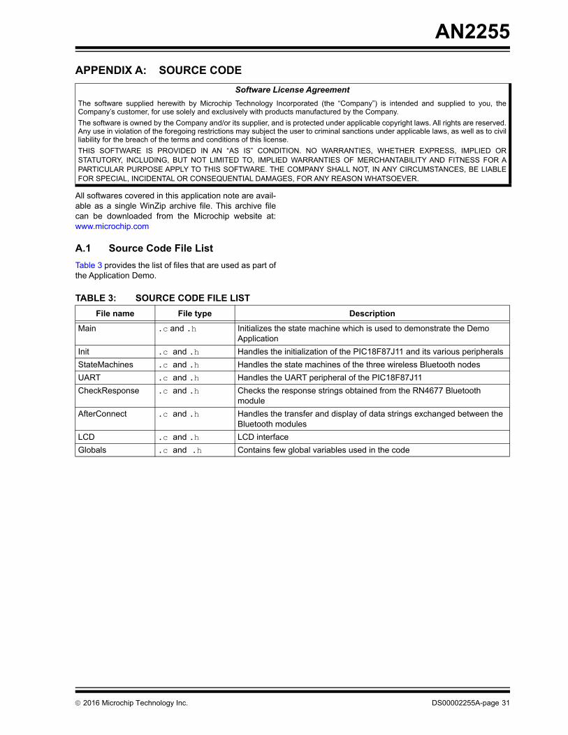
APPENDIX A: SOURCE CODE
All softwares covered in this application note are avail-able as a single WinZip archive file. This archive filecan be downloaded from the Microchip website at:www.microchip.com
A.1 Source Code File List
Table 3 provides the list of files that are used as part ofthe Application Demo.
Software License Agreement
The software supplied herewith by Microchip Technology Incorporated (the “Company”) is intended and supplied to you, theCompany’s customer, for use solely and exclusively with products manufactured by the Company.
The software is owned by the Company and/or its supplier, and is protected under applicable copyright laws. All rights are reserved.Any use in violation of the foregoing restrictions may subject the user to criminal sanctions under applicable laws, as well as to civilliability for the breach of the terms and conditions of this license.
THIS SOFTWARE IS PROVIDED IN AN “AS IS” CONDITION. NO WARRANTIES, WHETHER EXPRESS, IMPLIED ORSTATUTORY, INCLUDING, BUT NOT LIMITED TO, IMPLIED WARRANTIES OF MERCHANTABILITY AND FITNESS FOR APARTICULAR PURPOSE APPLY TO THIS SOFTWARE. THE COMPANY SHALL NOT, IN ANY CIRCUMSTANCES, BE LIABLEFOR SPECIAL, INCIDENTAL OR CONSEQUENTIAL DAMAGES, FOR ANY REASON WHATSOEVER.
TABLE 3: SOURCE CODE FILE LIST
File name File type Description
Main .c and .h Initializes the state machine which is used to demonstrate the Demo Application
Init .c and .h Handles the initialization of the PIC18F87J11 and its various peripherals
StateMachines .c and .h Handles the state machines of the three wireless Bluetooth nodes
UART .c and .h Handles the UART peripheral of the PIC18F87J11
CheckResponse .c and .h Checks the response strings obtained from the RN4677 Bluetooth module
AfterConnect .c and .h Handles the transfer and display of data strings exchanged between the Bluetooth modules
LCD .c and .h LCD interface
Globals .c and .h Contains few global variables used in the code
2016 Microchip Technology Inc. DS00002255A-page 31
AN
2255
DS
00002255A
-page 32
2016 M
icrochip Technolo
gy Inc.
tate_Machine BTC_Cmd_State_Machine
sponse_LE Check_Response_BTC
Receive_UART Clear_Receive_Buffer
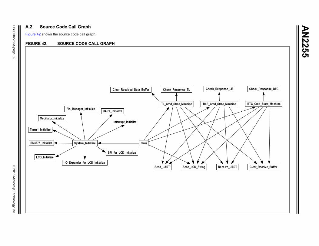
A.2 Source Code Call Graph
Figure 42 shows the source code call graph.
FIGURE 42: SOURCE CODE CALL GRAPH
Oscillator_Initialize
Timer1_Initialize
RN4677_Initialize System_Initialize
LCD_InitializeIO_Expander_for_LCD_Initialize
SPI_for_LCD_Initialize
Pin_Manager_Initialize UART_Initialize
Interrupt_Initialize
main
Clear_Received_Data_Buffer
TL_Cmd_State_Machine BLE_Cmd_S
Check_Response_TL Check_Re
Send_UART Send_LCD_String
AN2255
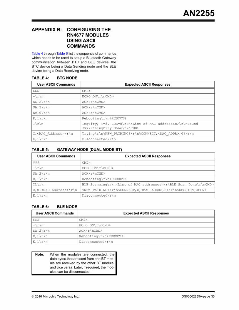
APPENDIX B: CONFIGURING THE RN4677 MODULES USING ASCII COMMANDS
Table 4 through Table 6 list the sequence of commandswhich needs to be used to setup a Bluetooth Gatewaycommunication between BTC and BLE devices, theBTC device being a Data Sending node and the BLEdevice being a Data Receiving node.
TABLE 4: BTC NODE
User ASCII Commands Expected ASCII Responses
$$$ CMD>
+\r\n ECHO ON\r\nCMD>
SG,2\r\n AOK\r\nCMD>
SA,2\r\n AOK\r\nCMD>
SM,0\r\n AOK\r\nCMD>
R,1\r\n Rebooting\r\n%REBOOT%
I\r\n Inquiry, T=8, COD=0\r\n<List of MAC addresses>\r\nFound <x>\r\nInquiry Done\r\nCMD>
C,<MAC_Address>\r\n Trying\r\n%NEW_PAIRING%\r\n%CONNECT,<MAC_ADDR>,0%/r/n
K,1\r\n Disconnected\r\n
TABLE 5: GATEWAY NODE (DUAL MODE BT)
User ASCII Commands Expected ASCII Responses
$$$ CMD>
+\r\n ECHO ON\r\nCMD>
SA,2\r\n AOK\r\nCMD>
R,1\r\n Rebooting\r\n%REBOOT%
IL\r\n BLE Scanning\r\n<List of MAC addresses>\r\BLE Scan Done\r\nCMD>
C,0,<MAC_Address>\r\n %NEW_PAIRING%\r\n%CONNECT,0,<MAC_ADDR>,2%\r\n%SESSION_OPEN%
K,1\r\n Disconnected\r\n
TABLE 6: BLE NODE
User ASCII Commands Expected ASCII Responses
$$$ CMD>
+\r\n ECHO ON\r\nCMD>
SA,2\r\n AOK\r\nCMD>
R,1\r\n Rebooting\r\n%REBOOT%
K,1\r\n Disconnected\r\n
Note: When the modules are connected, thedata bytes that are sent from one BT mod-ule are received by the other BT module,and vice versa. Later, if required, the mod-ules can be disconnected.
2016 Microchip Technology Inc. DS00002255A-page 33
AN2255
NOTES:
DS00002255A-page 34 2016 Microchip Technology Inc.
Note the following details of the code protection feature on Microchip devices:
• Microchip products meet the specification contained in their particular Microchip Data Sheet.
• Microchip believes that its family of products is one of the most secure families of its kind on the market today, when used in the intended manner and under normal conditions.
• There are dishonest and possibly illegal methods used to breach the code protection feature. All of these methods, to our knowledge, require using the Microchip products in a manner outside the operating specifications contained in Microchip’s Data Sheets. Most likely, the person doing so is engaged in theft of intellectual property.
• Microchip is willing to work with the customer who is concerned about the integrity of their code.
• Neither Microchip nor any other semiconductor manufacturer can guarantee the security of their code. Code protection does not mean that we are guaranteeing the product as “unbreakable.”
Code protection is constantly evolving. We at Microchip are committed to continuously improving the code protection features of ourproducts. Attempts to break Microchip’s code protection feature may be a violation of the Digital Millennium Copyright Act. If such actsallow unauthorized access to your software or other copyrighted work, you may have a right to sue for relief under that Act.
Information contained in this publication regarding deviceapplications and the like is provided only for your convenienceand may be superseded by updates. It is your responsibility toensure that your application meets with your specifications.MICROCHIP MAKES NO REPRESENTATIONS ORWARRANTIES OF ANY KIND WHETHER EXPRESS ORIMPLIED, WRITTEN OR ORAL, STATUTORY OROTHERWISE, RELATED TO THE INFORMATION,INCLUDING BUT NOT LIMITED TO ITS CONDITION,QUALITY, PERFORMANCE, MERCHANTABILITY ORFITNESS FOR PURPOSE. Microchip disclaims all liabilityarising from this information and its use. Use of Microchipdevices in life support and/or safety applications is entirely atthe buyer’s risk, and the buyer agrees to defend, indemnify andhold harmless Microchip from any and all damages, claims,suits, or expenses resulting from such use. No licenses areconveyed, implicitly or otherwise, under any Microchipintellectual property rights unless otherwise stated.
2016 Microchip Technology Inc.
Microchip received ISO/TS-16949:2009 certification for its worldwide headquarters, design and wafer fabrication facilities in Chandler and Tempe, Arizona; Gresham, Oregon and design centers in California and India. The Company’s quality system processes and procedures are for its PIC® MCUs and dsPIC® DSCs, KEELOQ® code hopping devices, Serial EEPROMs, microperipherals, nonvolatile memory and analog products. In addition, Microchip’s quality system for the design and manufacture of development systems is ISO 9001:2000 certified.
QUALITYMANAGEMENTSYSTEMCERTIFIEDBYDNV
== ISO/TS16949==
Trademarks
The Microchip name and logo, the Microchip logo, AnyRate, dsPIC, FlashFlex, flexPWR, Heldo, JukeBlox, KeeLoq, KeeLoq logo, Kleer, LANCheck, LINK MD, MediaLB, MOST, MOST logo, MPLAB, OptoLyzer, PIC, PICSTART, PIC32 logo, RightTouch, SpyNIC, SST, SST Logo, SuperFlash and UNI/O are registered trademarks of Microchip Technology Incorporated in the U.S.A. and other countries.
ClockWorks, The Embedded Control Solutions Company, ETHERSYNCH, Hyper Speed Control, HyperLight Load, IntelliMOS, mTouch, Precision Edge, and QUIET-WIRE are registered trademarks of Microchip Technology Incorporated in the U.S.A.
Analog-for-the-Digital Age, Any Capacitor, AnyIn, AnyOut, BodyCom, chipKIT, chipKIT logo, CodeGuard, dsPICDEM, dsPICDEM.net, Dynamic Average Matching, DAM, ECAN, EtherGREEN, In-Circuit Serial Programming, ICSP, Inter-Chip Connectivity, JitterBlocker, KleerNet, KleerNet logo, MiWi, motorBench, MPASM, MPF, MPLAB Certified logo, MPLIB, MPLINK, MultiTRAK, NetDetach, Omniscient Code Generation, PICDEM, PICDEM.net, PICkit, , PureSilicon, RightTouch logo, REAL ICE, Ripple Blocker, Serial Quad I/O, SQI, SuperSwitcher, SuperSwitcher II, Total Endurance, TSHARC, USBCheck, VariSense, ViewSpan, WiperLock, Wireless DNA, and ZENA are trademarks of Microchip Technology Incorporated in the U.S.A. and other countries.
SQTP is a service mark of Microchip Technology Incorporated in the U.S.A.
Silicon Storage Technology is a registered trademark of Microchip Technology Inc. in other countries.
GestIC is a registered trademarks of Microchip Technology Germany II GmbH & Co. KG, a subsidiary of Microchip Technology Inc., in other countries.
All other trademarks mentioned herein are property of their respective companies.
© 2016, Microchip Technology Incorporated, Printed in the U.S.A., All Rights Reserved.
ISBN: 978-1-5224-0905-2
DS00002255A-page 35

DS00002255A-page 36 2016 Microchip Technology Inc.
AMERICASCorporate Office2355 West Chandler Blvd.Chandler, AZ 85224-6199Tel: 480-792-7200 Fax: 480-792-7277Technical Support: http://www.microchip.com/supportWeb Address: www.microchip.com
AtlantaDuluth, GA Tel: 678-957-9614 Fax: 678-957-1455
Austin, TXTel: 512-257-3370
BostonWestborough, MA Tel: 774-760-0087 Fax: 774-760-0088
ChicagoItasca, IL Tel: 630-285-0071 Fax: 630-285-0075
ClevelandIndependence, OH Tel: 216-447-0464 Fax: 216-447-0643
DallasAddison, TX Tel: 972-818-7423 Fax: 972-818-2924
DetroitNovi, MI Tel: 248-848-4000
Houston, TX Tel: 281-894-5983
IndianapolisNoblesville, IN Tel: 317-773-8323Fax: 317-773-5453
Los AngelesMission Viejo, CA Tel: 949-462-9523 Fax: 949-462-9608
New York, NY Tel: 631-435-6000
San Jose, CA Tel: 408-735-9110
Canada - TorontoTel: 905-695-1980 Fax: 905-695-2078
ASIA/PACIFICAsia Pacific OfficeSuites 3707-14, 37th FloorTower 6, The GatewayHarbour City, Kowloon
Hong KongTel: 852-2943-5100Fax: 852-2401-3431
Australia - SydneyTel: 61-2-9868-6733Fax: 61-2-9868-6755
China - BeijingTel: 86-10-8569-7000 Fax: 86-10-8528-2104
China - ChengduTel: 86-28-8665-5511Fax: 86-28-8665-7889
China - ChongqingTel: 86-23-8980-9588Fax: 86-23-8980-9500
China - DongguanTel: 86-769-8702-9880
China - GuangzhouTel: 86-20-8755-8029
China - HangzhouTel: 86-571-8792-8115 Fax: 86-571-8792-8116
China - Hong Kong SARTel: 852-2943-5100 Fax: 852-2401-3431
China - NanjingTel: 86-25-8473-2460Fax: 86-25-8473-2470
China - QingdaoTel: 86-532-8502-7355Fax: 86-532-8502-7205
China - ShanghaiTel: 86-21-5407-5533 Fax: 86-21-5407-5066
China - ShenyangTel: 86-24-2334-2829Fax: 86-24-2334-2393
China - ShenzhenTel: 86-755-8864-2200 Fax: 86-755-8203-1760
China - WuhanTel: 86-27-5980-5300Fax: 86-27-5980-5118
China - XianTel: 86-29-8833-7252Fax: 86-29-8833-7256
ASIA/PACIFICChina - XiamenTel: 86-592-2388138 Fax: 86-592-2388130
China - ZhuhaiTel: 86-756-3210040 Fax: 86-756-3210049
India - BangaloreTel: 91-80-3090-4444 Fax: 91-80-3090-4123
India - New DelhiTel: 91-11-4160-8631Fax: 91-11-4160-8632
India - PuneTel: 91-20-3019-1500
Japan - OsakaTel: 81-6-6152-7160 Fax: 81-6-6152-9310
Japan - TokyoTel: 81-3-6880- 3770 Fax: 81-3-6880-3771
Korea - DaeguTel: 82-53-744-4301Fax: 82-53-744-4302
Korea - SeoulTel: 82-2-554-7200Fax: 82-2-558-5932 or 82-2-558-5934
Malaysia - Kuala LumpurTel: 60-3-6201-9857Fax: 60-3-6201-9859
Malaysia - PenangTel: 60-4-227-8870Fax: 60-4-227-4068
Philippines - ManilaTel: 63-2-634-9065Fax: 63-2-634-9069
SingaporeTel: 65-6334-8870Fax: 65-6334-8850
Taiwan - Hsin ChuTel: 886-3-5778-366Fax: 886-3-5770-955
Taiwan - KaohsiungTel: 886-7-213-7828
Taiwan - TaipeiTel: 886-2-2508-8600 Fax: 886-2-2508-0102
Thailand - BangkokTel: 66-2-694-1351Fax: 66-2-694-1350
EUROPEAustria - WelsTel: 43-7242-2244-39Fax: 43-7242-2244-393
Denmark - CopenhagenTel: 45-4450-2828 Fax: 45-4485-2829
France - ParisTel: 33-1-69-53-63-20 Fax: 33-1-69-30-90-79
Germany - DusseldorfTel: 49-2129-3766400
Germany - KarlsruheTel: 49-721-625370
Germany - MunichTel: 49-89-627-144-0 Fax: 49-89-627-144-44
Italy - Milan Tel: 39-0331-742611 Fax: 39-0331-466781
Italy - VeniceTel: 39-049-7625286
Netherlands - DrunenTel: 31-416-690399 Fax: 31-416-690340
Poland - WarsawTel: 48-22-3325737
Spain - MadridTel: 34-91-708-08-90Fax: 34-91-708-08-91
Sweden - StockholmTel: 46-8-5090-4654
UK - WokinghamTel: 44-118-921-5800Fax: 44-118-921-5820
Worldwide Sales and Service
06/23/16