Embed Size (px)
Citation preview
1/8H48.5200LS027EN-0 11.2017
ALU 5200-DS-E RC2Assembly instructions
RC2
Double-sash, rectangular turn-only secondary sash
Burglar resistance RC2
Aluminum Euronut 15/20
Chamber dimension 21
Version A0004/A0006/A0022
Size range Application for E-test in accordance with DIN EN 1627ff RC2, RC2 N
Window Patio door
Sash width (mm) 565 – 1250 565 – 1250
Sash height (for coupling set ALU-E with lockable handle ALU Pos. 101/103)
(mm) 770 – 2000 2000 – 2400
Sash height (for gear set ALU-E with lockable handle TITAN Pos. 105)
(mm) 805 – 2000 2000 – 2400
Sash weight (kg) max. 100/130/150 max. 100/130/150
The following application diagrams apply: -H58.AWDLS003EN max. 100 kg -H58.AWDLS004EN max. 130 kgRequired documentation for primary sash: -H48.5200LS024EN ALU 5200-DK E RC2 -H48.5200LS025EN ALU 5200-TBT E RC2 -H48.5200LS026EN ALU 5200-D/ZV E RC2
Profile recommendation: -H48.ZubhLS008ENMaintenance - and adjustment instructions: -H45.5200LS004ENIt is essential to observe:-Specifications/references to the product and liability (Directive VHBH as well as other applicable documents)!-Information provided by profile manufacturers or system owners for windows and window doors!
11.20172/8 H48.5200LS027EN-0H48.5200LS027EN-0 11.2017 3/8
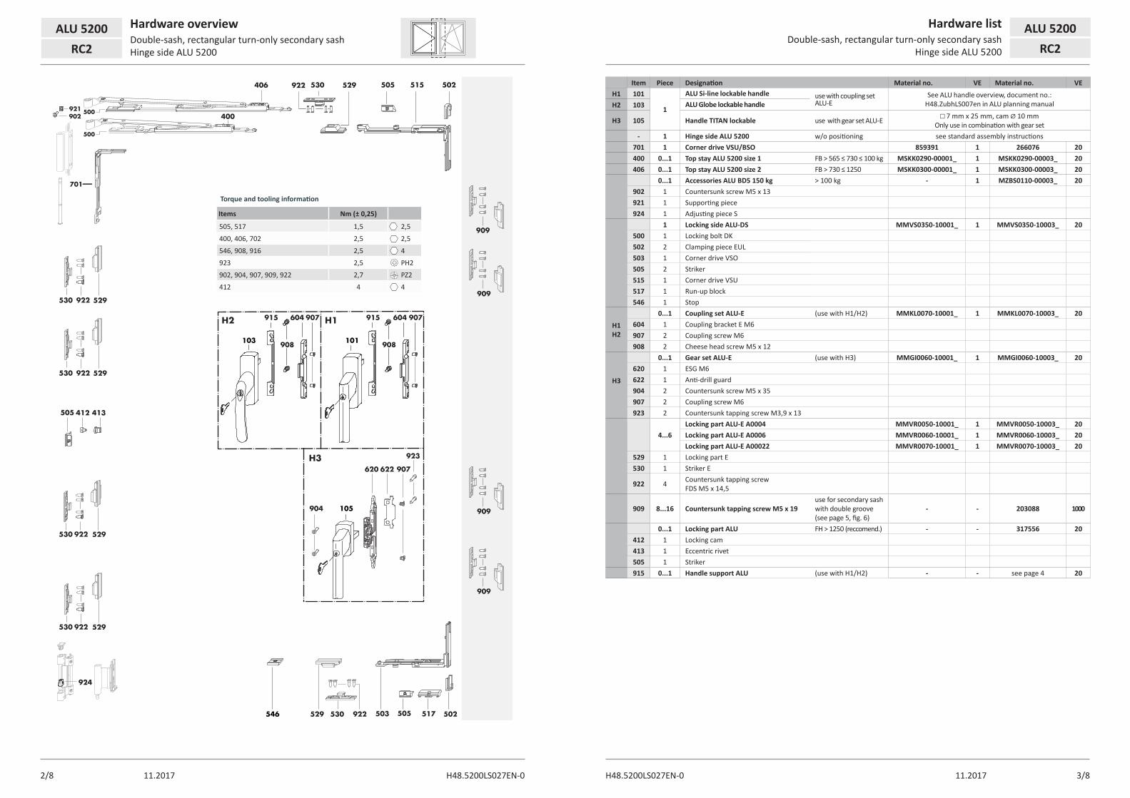
ALU 5200 Hardware overviewDouble-sash, rectangular turn-only secondary sash Hinge side ALU 5200RC2
Item Piece Designation Material no. VE Material no. VEH1 101
1
ALU Si-line lockable handle use with coupling set ALU-E
See ALU handle overview, document no.: H48.ZubhLS007en in ALU planning manualH2 103 ALU Globe lockable handle
H3 105 Handle TITAN lockable use with gear set ALU-E □ 7 mm x 25 mm, cam Ø 10 mm Only use in combination with gear set
- 1 Hinge side ALU 5200 w/o positioning see standard assembly instructions701 1 Corner drive VSU/BSO 859391 1 266076 20400 0...1 Top stay ALU 5200 size 1 FB > 565 ≤ 730 ≤ 100 kg MSKK0290-00001_ 1 MSKK0290-00003_ 20406 0...1 Top stay ALU 5200 size 2 FB > 730 ≤ 1250 MSKK0300-00001_ 1 MSKK0300-00003_ 20
0...1 Accessories ALU BD5 150 kg > 100 kg - 1 MZBS0110-00003_ 20902 1 Countersunk screw M5 x 13921 1 Supporting piece924 1 Adjusting piece S
1 Locking side ALU-DS MMVS0350-10001_ 1 MMVS0350-10003_ 20500 1 Locking bolt DK502 2 Clamping piece EUL503 1 Corner drive VSO505 2 Striker515 1 Corner drive VSU517 1 Run-up block546 1 Stop
H1 H2
0...1 Coupling set ALU-E (use with H1/H2) MMKL0070-10001_ 1 MMKL0070-10003_ 20604 1 Coupling bracket E M6907 2 Coupling screw M6908 2 Cheese head screw M5 x 12
H3
0...1 Gear set ALU-E (use with H3) MMGI0060-10001_ 1 MMGI0060-10003_ 20620 1 ESG M6622 1 Anti-drill guard904 2 Countersunk screw M5 x 35907 2 Coupling screw M6923 2 Countersunk tapping screw M3,9 x 13
4...6Locking part ALU-E A0004 MMVR0050-10001_ 1 MMVR0050-10003_ 20Locking part ALU-E A0006 MMVR0060-10001_ 1 MMVR0060-10003_ 20Locking part ALU-E A00022 MMVR0070-10001_ 1 MMVR0070-10003_ 20
529 1 Locking part E530 1 Striker E
922 4 Countersunk tapping screw FDS M5 x 14,5
909 8...16 Countersunk tapping screw M5 x 19use for secondary sash with double groove (see page 5, fig. 6)
- - 203088 1000
0...1 Locking part ALU FH > 1250 (reccomend.) - - 317556 20412 1 Locking cam413 1 Eccentric rivet505 1 Striker915 0...1 Handle support ALU (use with H1/H2) - - see page 4 20
Hardware listDouble-sash, rectangular turn-only secondary sash
Hinge side ALU 5200
ALU 5200RC2
Torque and tooling information
Items Nm (± 0,25)
505, 517 1,5 2,5
400, 406, 702 2,5 2,5
546, 908, 916 2,5 4
923 2,5 PH2
902, 904, 907, 909, 922 2,7 PZ2
412 4 4
413412505
922 529530
922 529530
924
922
909
909
909
909
529530
922 529530
530922 529
546
101103
H1H2 604
908
915 907 604
908
915 907
923
907622620
904 105
H3
502515505
505503 517 502922530529
406
400902921
701
500
500
11.20174/8 H48.5200LS027EN-0H48.5200LS027EN-0 11.2017 5/8
Installation, variants of jigsDouble-sash, rectangular turn-only secondary sash
Hinge side ALU 5200
ALU 5200RC2
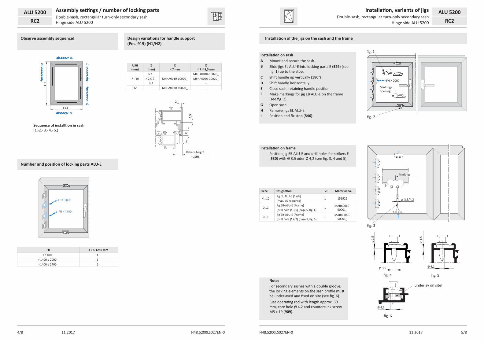
ALU 5200 Assembly settings / number of locking partsDouble-sash, rectangular turn-only secondary sash Hinge side ALU 5200RC2
USH (mm)
Z (mm)
X ≤ 7 mm
X < 7 ≤ 8,5 mm
7 - 10≤ 2
MFHA0010-10020_MFHA0010-10020_
> 2 ≤ 3 MFHA0020-10020_> 3 -
12 - MFHA0030-10020_ -
FH FB ≤ 1250 mm
≤ 1400 4> 1400 ≤ 2000 5> 1400 ≤ 2400 6
Observe assembly sequence!
Number and position of locking parts ALU-E
Design variations for handle support (Pos. 915) (H1/H2)
Sequence of installtion in sash:(1.-2.- 3.- 4.- 5.)
Rebate height(USH)
2
Z
X1,
5
4.
3.
5.
FB2
FH
1.
2.
FH > 2000
FH > 1400
Installation of the jigs on the sash and the frame
Installation on sashA Mount and secure the sash.B Slide jigs EL ALU-E into locking parts E (529) (see
fig. 1) up to the stop.C Shift handle up vertically (180°)D Shift handle horizontally.E Close sash, retaining handle position.F Make markings for jig EB ALU-E on the frame
(see fig. 2).G Open sash.H Remove jigs EL ALU-E.I Position and fix stop (546).
Installation on framePosition jig EB ALU-E and drill holes for strikers E (530) with Ø 3,5 oder Ø 4,2 (see fig. 3, 4 and 5).
Piece Designation VE Material no.
4...10Jig EL ALU-E (Sash)
1 156926(max. 10 required)
0...1Jig EB-ALU-E (Frame)
1 MARB0060-50001_(drill hole Ø 3,5) (page 5, fig. 4)
0...1Jig EB-ALU-E (Frame)
1 MARB0040-50001_(drill hole Ø 4,2) (page 5, fig. 5)
3,5/4,2
fig. 1
fig. 2
Marking- opening
FH > 2000
fig. 3
fig. 6
Marking
fig. 4 fig. 5
underlay on site!
≤ 1,
5
> 1,
5
Ø 3,5 Ø 4,2
Ø 4,2
Note:For secondary sashes with a double groove, the locking elements on the sash profile must be underlayed and fixed on site (see fig. 6).(use operating rod with length approx. 60 mm, core hole Ø 4.2 and countersunk screw M5 x 19 (909).
11.20176/8 H48.5200LS027EN-0H48.5200LS027EN-0 11.2017 7/8
7,5
S10 = 135(85) 50
105,2
5,2
5,210 10
50
50,2
S7
= G
2 -
675,
2S6
= G
1 - 1
03
S7 =
G2
- 11
0
1)
X
X
5,2
S6 =
G1
- 110
H1/H2 H3
S9 =
FH
- 33
6
8585
FH/2
- 18
0
FH/3
- 18
0 (F
H >
200
0)
FH/2
- 95
(140
0 <
FH ≤
200
0)
FH/3
- 10
9 (F
H >
200
0)
10 +0
,1
FB (sash width)
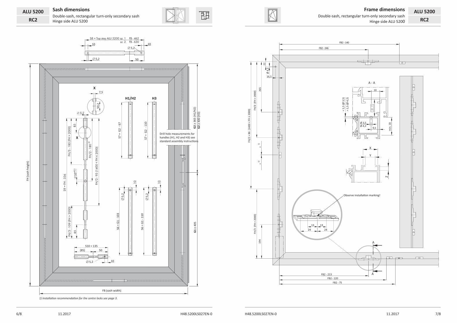
1) Installation recommendation for the centre locks see page 3.
Drill hole measurements for handles (H1, H2 and H3) see standard assembly instructions
G1
≥ 40
5G
2 ≥
400
(H3)
G2
≥ 36
5 (H
1/H2
)
ALU 5200 Sash dimensionsDouble-sash, rectangular turn-only secondary sash Hinge side ALU 5200RC2
Frame dimensionsDouble-sash, rectangular turn-only secondary sash
Hinge side ALU 5200
ALU 5200RC2
S8 = Top stay ALU 5200 sz. 1 FB - 462 sz. 2 FB - 630
FH
(sas
h he
ight
)
FB2 - 213 FB2 - 120
FB2 - 75
194
FH/3
(FH
> 2
000)
FH/3
(FH
> 2
000)
=
=
A
A
265
13 1324 24
FH/2
+ 8
6 (1
400
< FH
≤ 2
000)
10
min
. 18
< 1,
5 (Ø
3,5
)
Z
> 1,
5 (Ø
4,2
)
Ø 3,5Ø 4,2
9,5
A - A
X Y
1)1)
FB2 - 246
FB2 - 140
22
Ø 4
,2
16,5
Observe installation marking!

H48.
axnt
LS03
6EN
www.siegenia.com