Embed Size (px)
Citation preview
1
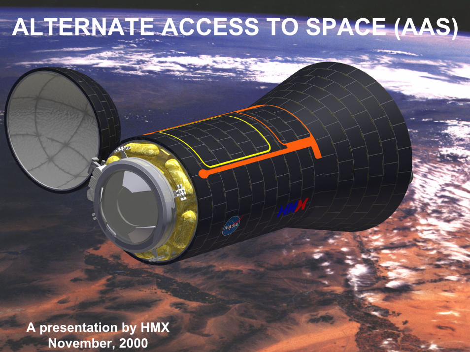
ALTERNATE ACCESS TO SPACE (AAS)
A presentation by HMXNovember, 2000
2
This PowerPoint file represents a distillation of the Alternate Access to Space (AAS) final report presented November 6, 2000 under contract to the NASA Marshall Spaceflight Center. Out of a field of 17 small business bidders, HMX, Microcosm, Andrews Space & Tech, and Kistler Aerospace were selected to perform concept studies of alternate methods for "contingency" resupply of the International Space Station. (Other contracts, to Boeing, Lockheed, Orbital and Coleman were awarded non-competitively.) Per the NASA Act of 1958, this information should have been made publicly available but the results were largely suppressed in order to kill the AAS program, which had been imposed on NASA by OMB and the Congress against NASA's will. Especially opposed to AAS was the Johnson Space Flight Center, on the grounds that any alternate to the Space Shuttle would reduce the need for expensive and dangerous Shuttle missions, and reduce the available flights for the large pool of unflown NASA astronauts. Also strongly obstructionist was Marshall's Dennis Smith, then SLI program manager and now in charge of the Orbital Space Plane (OSP) who simply wanted the money to be used for his massive Space Launch Initiative (SLI) boondoggle.
HMX determined that use of a fully proven launcher, the Titan II, would have allowed AAS missions to the station to begin in 2003 for half the money approved by OMB for this program. Instead of acting, NASA/ MSFC delayed the AAS program, and watered it down until for all practical purposes it became a technology research effort on the methods of docking unmanned vehicles to the ISS. While small follow-on contracts have been awarded, the program is set to terminate in early summer, and the OSP project will absorb the remaining funds.
While the AAS program never intended the resupply vehicle to be crewed, HMX found that the only way to perform the mission was to build a reusable AAS transfer vehicle (designated the XV). This approach was also adopted by other AAS contractors. Reuse of the XV reduced per flight costs and enhanced reliability, but it also meant that the vehicle could serve as both a lifeboat for the ISS and also carry crews to orbit. Of course, given the vicious opposition to AAS on the part of JSC, HMX never briefed the manned option, but the last slide in this presentation illustrates one version of a crewed XV.
It is ironic, in light of the Columbia disaster, that this capability would just now be coming on line if NASA had not badly bungled the entire program. Given NASA's track record of not being able to successfully complete a single space transportation project (e.g., X-33, X-34, X-37, X-43, X-38 and the SLI program) in the past twenty years, plus their mismanagement of the Shuttle program, one wonders why they should be entrusted with the development of the OSP. Only Congress can answer that question.
Gary C. Hudson, CEO, HMX March 1, 2003
3
RequirementsRequirements
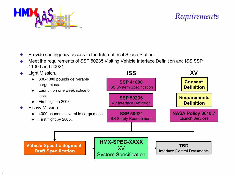
Provide contingency access to the International Space Station.Meet the requirements of SSP 50235 Visiting Vehicle Interface Definition and ISS SSP 41000 and 50021.Light Mission.
300-1000 pounds deliverable cargo mass.Launch on one week notice or less.First flight in 2003.
Heavy Mission.4000 pounds deliverable cargo mass.First flight by 2005.
SSP 50021ISS Safety Requirements
SSP 41000ISS System Specification
TBDInterface Control Documents
SSP 50235VV Interface Definition
Concept Definition
ISS XV
HMX-SPEC-XXXXXV
System Specification
Vehicle Specific Segment Draft Specification
RequirementsDefinition
NASA Policy 8610.7Launch Services
4
Top Level Requirements FlowdownTop Level Requirements Flowdown
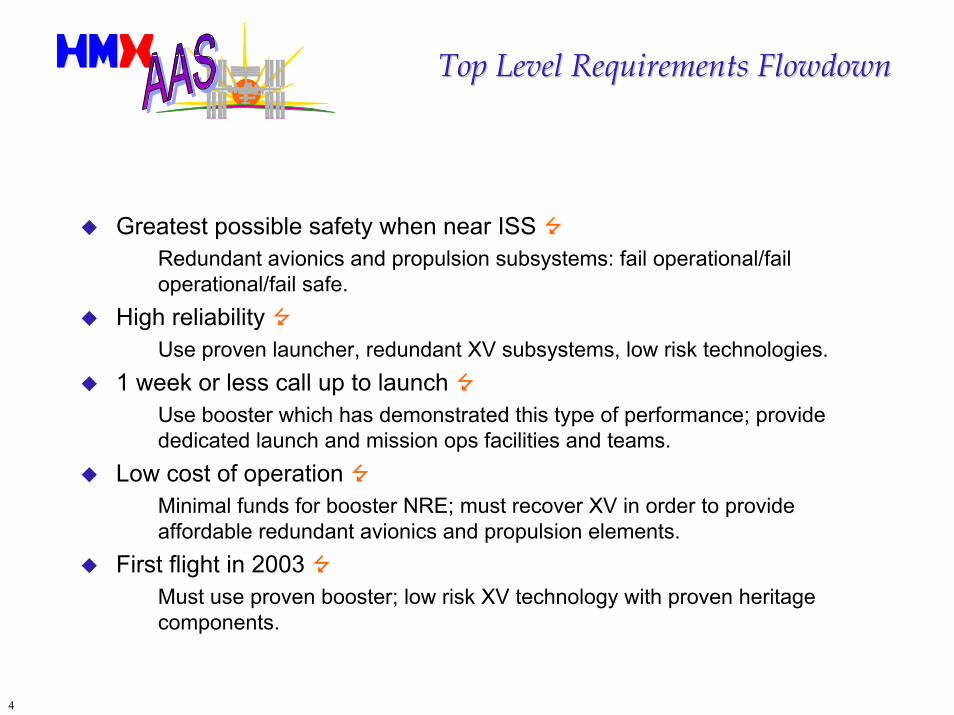
Greatest possible safety when near ISS Redundant avionics and propulsion subsystems: fail operational/fail operational/fail safe.
High reliability Use proven launcher, redundant XV subsystems, low risk technologies.
1 week or less call up to launch Use booster which has demonstrated this type of performance; provide dedicated launch and mission ops facilities and teams.
Low cost of operation Minimal funds for booster NRE; must recover XV in order to provide affordable redundant avionics and propulsion elements.
First flight in 2003 Must use proven booster; low risk XV technology with proven heritage components.
5
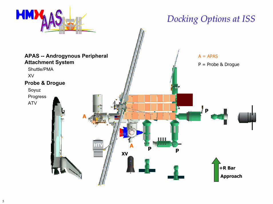
Docking Options at ISSDocking Options at ISS
APAS -- Androgynous Peripheral Attachment System
Shuttle/PMAXV
Probe & DrogueSoyuzProgressATV
A = APAS
P = Probe & Drogue
A
A P P
P
+R Bar
Approach
XV
HTV
6
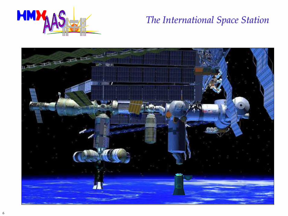
The International Space StationThe International Space Station
7
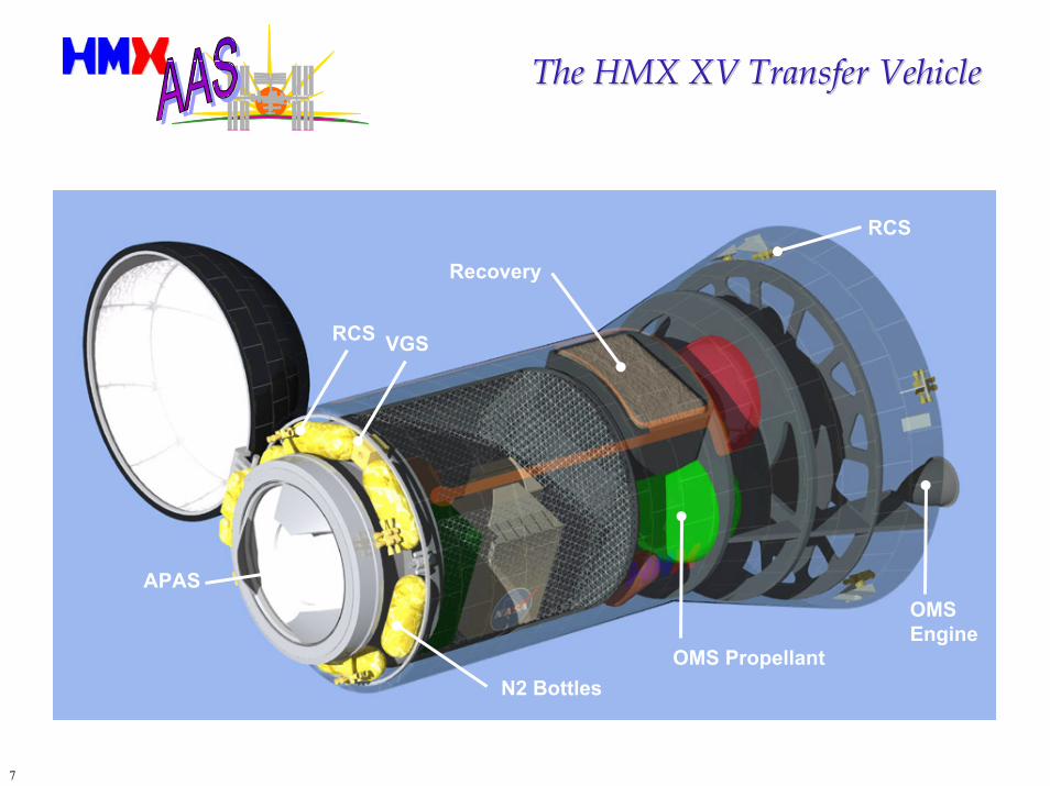
The HMX XV Transfer VehicleThe HMX XV Transfer Vehicle
APAS
Recovery
RCS
OMS Propellant
RCS
VGS
OMSEngine
N2 Bottles
8
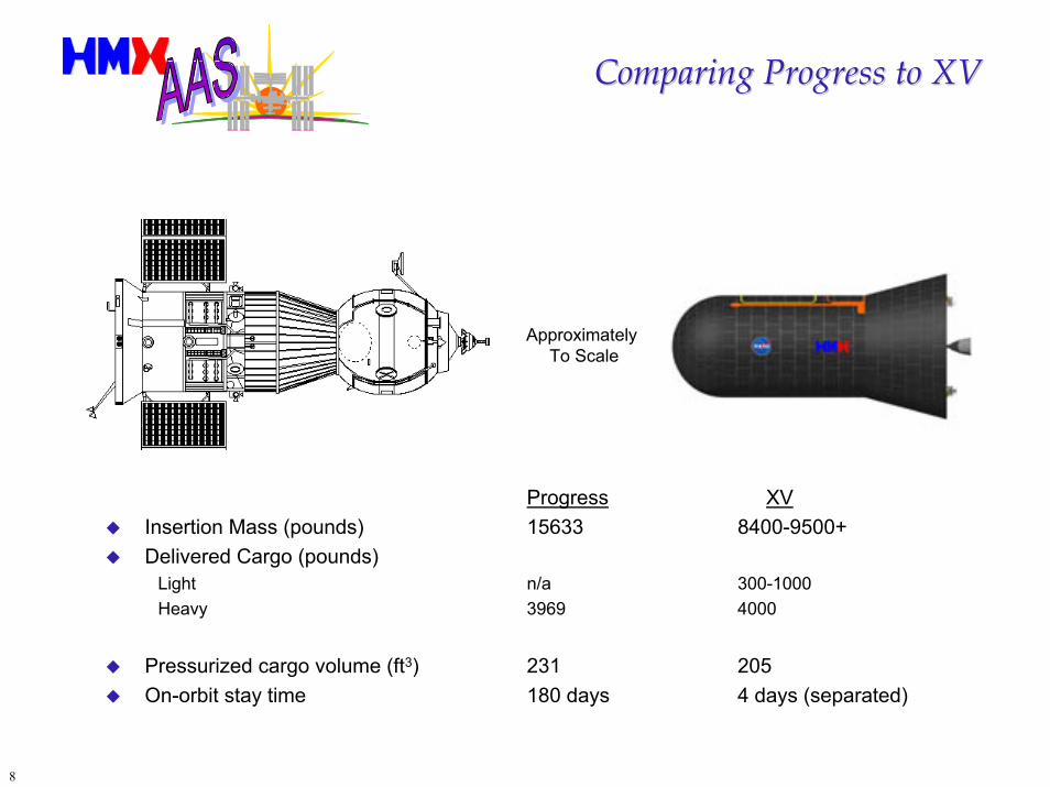
Comparing Progress to XVComparing Progress to XV
Approximately To Scale
Progress XVInsertion Mass (pounds) 15633 8400-9500+Delivered Cargo (pounds)
Light n/a 300-1000Heavy 3969 4000
Pressurized cargo volume (ft3) 231 205On-orbit stay time 180 days 4 days (separated)
9
Why Reusability?Why Reusability?
Reusability offers two significant advantages contrasted with an expendable transfer spacecraft:
First, the spacecraft can be built with much more redundancy for the same dollars since the cost is now to be amortized over whatever number of flights the vehicle can perform. Or if the redundancy is required by the customer (as in the case of AAS) the cost per flight can be lowered through reuse of the spacecraft.
Reuse of a complicated spacecraft is not new. A Gemini spacecraft was reflown, and the Russian Merkur was designed for routine reuse.
Second, if something works on one flight it is reasonable to assume that it will work again on subsequent flights. Airlines have learned this and as a result adopted, nearly twenty years ago, “on condition maintenance.” In other words, don’t fix it if it isn’t broken.
Failures which do not result in loss of vehicle are recorded by on-board computers and/or telemetry or are uncovered by post-flight inspection. This permits HMX to fix problems before they become serious enough to jeopardize either safety or future mission completion.
10
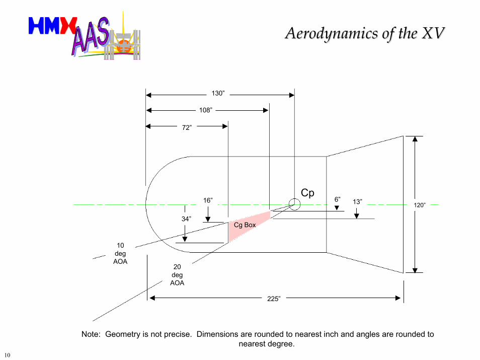
Aerodynamics of the XVAerodynamics of the XV
130”
108”
72”
10 deg AOA
20 deg AOA
Cg Box
16”
34”
6” 13” 120”
225”
Cp
Note: Geometry is not precise. Dimensions are rounded to nearest inch and angles are rounded to nearest degree.
11
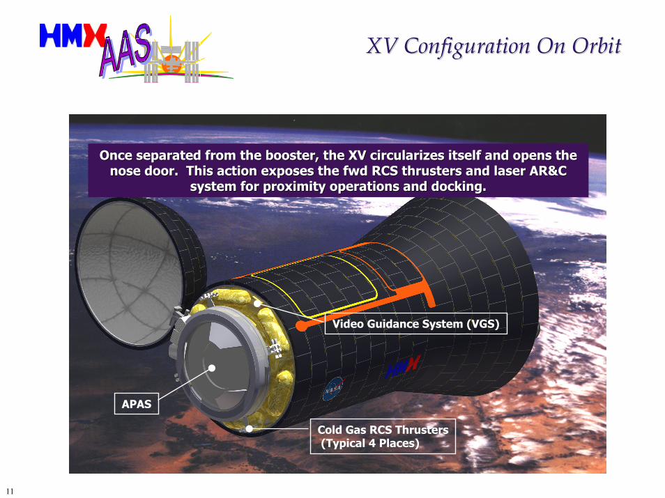
XV Configuration On OrbitXV Configuration On Orbit
Once separated from the booster, the XV circularizes itself and Once separated from the booster, the XV circularizes itself and opens the opens the nose door. This action exposes the fwd RCS thrusters and laser nose door. This action exposes the fwd RCS thrusters and laser AR&C AR&C
system for proximity operations and docking.system for proximity operations and docking.
Cold Gas RCS Thrusters(Typical 4 Places)
Video Guidance System (VGS)
APAS
12
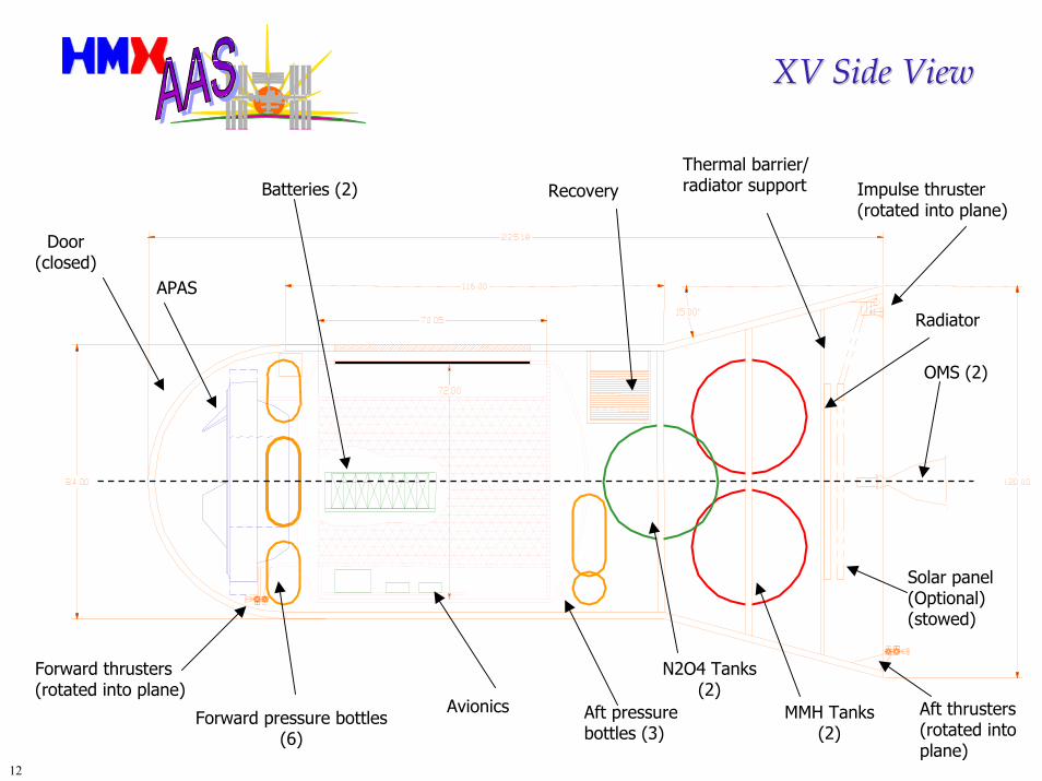
XV Side ViewXV Side View
N2O4 Tanks(2)
MMH Tanks(2)
Aft thrusters(rotated intoplane)
OMS (2)
Forward pressure bottles(6)
Aft pressurebottles (3)
Avionics
Forward thrusters(rotated into plane)
APAS
Door(closed)
Radiator
Solar panel(Optional)(stowed)
Batteries (2)Thermal barrier/radiator support Impulse thruster
(rotated into plane)Recovery
13
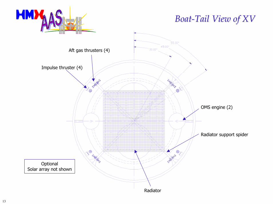
BoatBoat--Tail View of XVTail View of XV
Impulse thruster (4)
Aft gas thrusters (4)
OMS engine (2)
Radiator
Radiator support spider
OptionalSolar array not shown
14
XV SubsystemsXV Subsystems
AirframeAll Carbon-epoxy using proprietary techniques, separate inner cargo cabin.
Avionics & SoftwareIntegrated INAV/GPS with attitude and flight computer, triple redundant with separate and independent CAM/entry backup system, automated docking with “pilot’s assistant”, USN for command up and downlink, S-Band up and downlink comm via USN, SSCS space to space comm system, flight termination system for booster.
OMSNTO/MMH with R40B dual thrusters, all components redundant or isolated via latching valves.
RCSCold nitrogen gas, completely redundant.
Environmental ControlLoop heat pipe, redundant.
Electrical PowerPower storage and distribution, redundant primary batteries, backup CAM battery.
Docking APAS, strobes, running lights, video cameras, laser VGS, separate laser rangefinder.
Thermal ProtectionAETB type tiles over 100% of surface.
LandingDrogue, main chutes, PMA and stroking skid gear.
15
XV Avionics SystemXV Avionics System
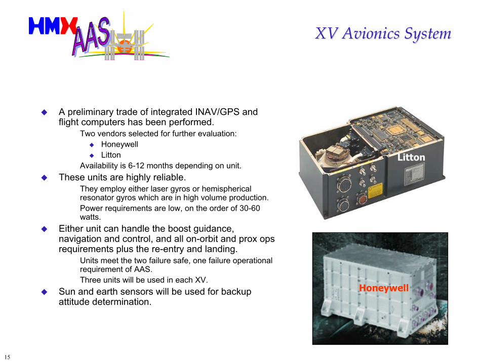
A preliminary trade of integrated INAV/GPS and flight computers has been performed.
Two vendors selected for further evaluation:HoneywellLitton
Availability is 6-12 months depending on unit.These units are highly reliable.
They employ either laser gyros or hemispherical resonator gyros which are in high volume production.Power requirements are low, on the order of 30-60 watts.
Either unit can handle the boost guidance, navigation and control, and all on-orbit and prox ops requirements plus the re-entry and landing.
Units meet the two failure safe, one failure operational requirement of AAS.Three units will be used in each XV.
Sun and earth sensors will be used for backup attitude determination.
Litton
Honeywell
16
Video Guidance Sensor and TargetVideo Guidance Sensor and Target
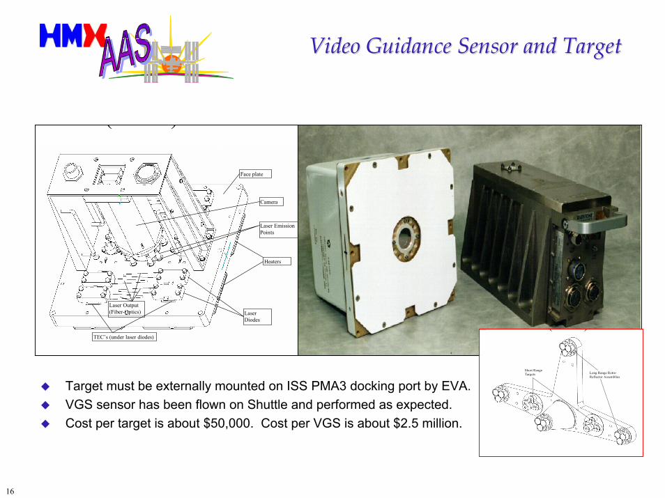
Target must be externally mounted on ISS PMA3 docking port by EVA.VGS sensor has been flown on Shuttle and performed as expected.Cost per target is about $50,000. Cost per VGS is about $2.5 million.
Heaters
LaserDiodes
TEC’s (under laser diodes)
Laser Output(Fiber-Optics)
Camera
Laser EmissionPoints
Face plate
Short RangeTargets Long Range Retro-
Reflector Assemblies
( )
Target
VGS
( )
17
XV Electrical Power SubsystemXV Electrical Power Subsystem
Battery-only Electrical Power Subsystem DesignBatteries (2 Redundant)
Diode isolated for automatic redundancyOperate down to 50% depth of discharge for maximum cycle life as secondary cellOperate down to 20% depth of discharge in contingency as primary cellEach battery is capable of supporting an entire AAS mission as primary cell
Power Regulator
Solar Array Augmented Electrical Power Subsystem Design (Option)Photovoltaic Cell Array (Deployable/Retractable)
Array Power Shunt (Resistive Load)Power Buses (2 redundant)
Switch-Selected Redundant Battery & Regulator StringsCharge/Discharge Controller for Each BatteryRegulator for Each Power Bus
18
LithiumLithium--Ion Battery and AlternativesIon Battery and Alternatives
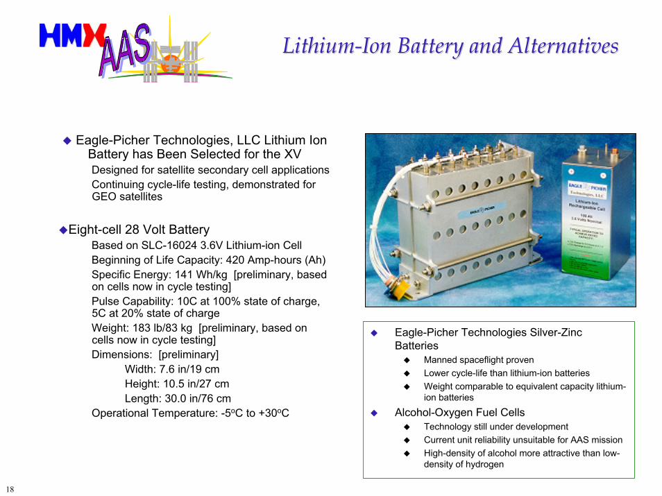
Eagle-Picher Technologies, LLC Lithium Ion Battery has Been Selected for the XVDesigned for satellite secondary cell applicationsContinuing cycle-life testing, demonstrated for GEO satellites
Eight-cell 28 Volt Battery Based on SLC-16024 3.6V Lithium-ion CellBeginning of Life Capacity: 420 Amp-hours (Ah)Specific Energy: 141 Wh/kg [preliminary, based on cells now in cycle testing]Pulse Capability: 10C at 100% state of charge, 5C at 20% state of chargeWeight: 183 lb/83 kg [preliminary, based on cells now in cycle testing]Dimensions: [preliminary]
Width: 7.6 in/19 cm Height: 10.5 in/27 cm Length: 30.0 in/76 cm
Operational Temperature: -5oC to +30oC
Eagle-Picher Technologies Silver-Zinc Batteries
Manned spaceflight provenLower cycle-life than lithium-ion batteriesWeight comparable to equivalent capacity lithium-ion batteries
Alcohol-Oxygen Fuel CellsTechnology still under developmentCurrent unit reliability unsuitable for AAS missionHigh-density of alcohol more attractive than low-density of hydrogen
19
Deployable Photovoltaic ArrayDeployable Photovoltaic Array
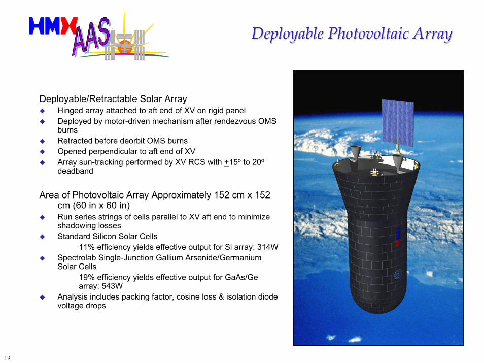
Deployable/Retractable Solar ArrayHinged array attached to aft end of XV on rigid panelDeployed by motor-driven mechanism after rendezvous OMS burnsRetracted before deorbit OMS burnsOpened perpendicular to aft end of XVArray sun-tracking performed by XV RCS with +15o to 20o
deadband
Area of Photovoltaic Array Approximately 152 cm x 152 cm (60 in x 60 in)Run series strings of cells parallel to XV aft end to minimize shadowing lossesStandard Silicon Solar Cells
11% efficiency yields effective output for Si array: 314WSpectrolab Single-Junction Gallium Arsenide/Germanium Solar Cells
19% efficiency yields effective output for GaAs/Ge array: 543W
Analysis includes packing factor, cosine loss & isolation diode voltage drops
20
XV APAS SystemXV APAS System
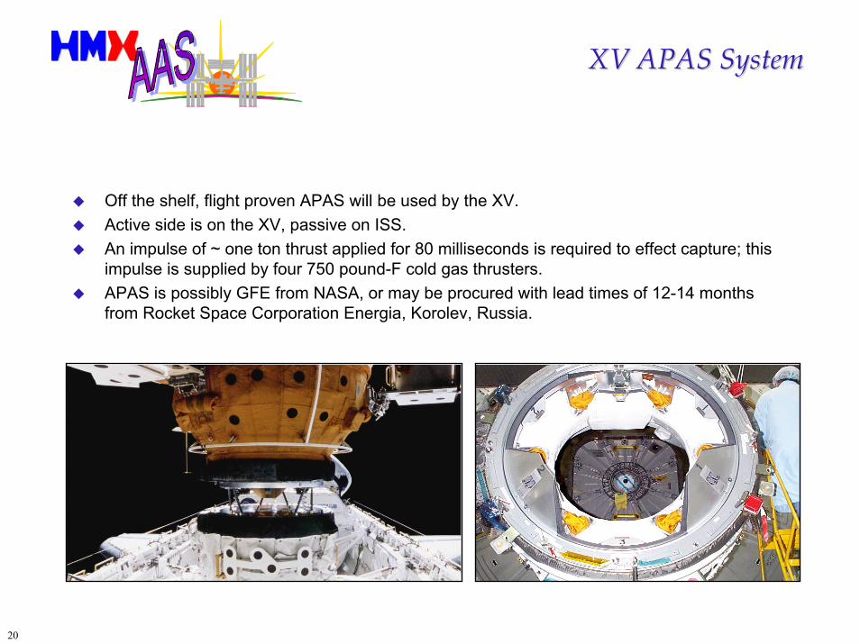
Off the shelf, flight proven APAS will be used by the XV.Active side is on the XV, passive on ISS.An impulse of ~ one ton thrust applied for 80 milliseconds is required to effect capture; this impulse is supplied by four 750 pound-F cold gas thrusters.APAS is possibly GFE from NASA, or may be procured with lead times of 12-14 months from Rocket Space Corporation Energia, Korolev, Russia.
21
XV Propulsion SystemXV Propulsion System
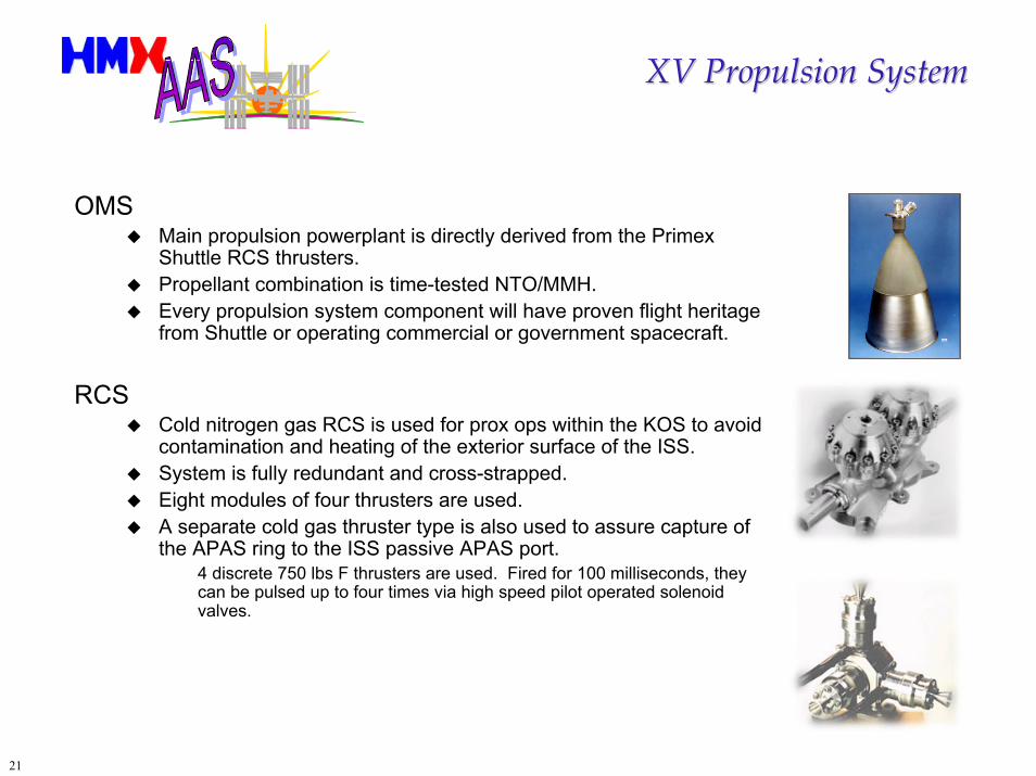
OMSMain propulsion powerplant is directly derived from the Primex Shuttle RCS thrusters. Propellant combination is time-tested NTO/MMH.Every propulsion system component will have proven flight heritage from Shuttle or operating commercial or government spacecraft.
RCSCold nitrogen gas RCS is used for prox ops within the KOS to avoid contamination and heating of the exterior surface of the ISS.System is fully redundant and cross-strapped. Eight modules of four thrusters are used.A separate cold gas thruster type is also used to assure capture of the APAS ring to the ISS passive APAS port.
4 discrete 750 lbs F thrusters are used. Fired for 100 milliseconds, they can be pulsed up to four times via high speed pilot operated solenoid valves.
22
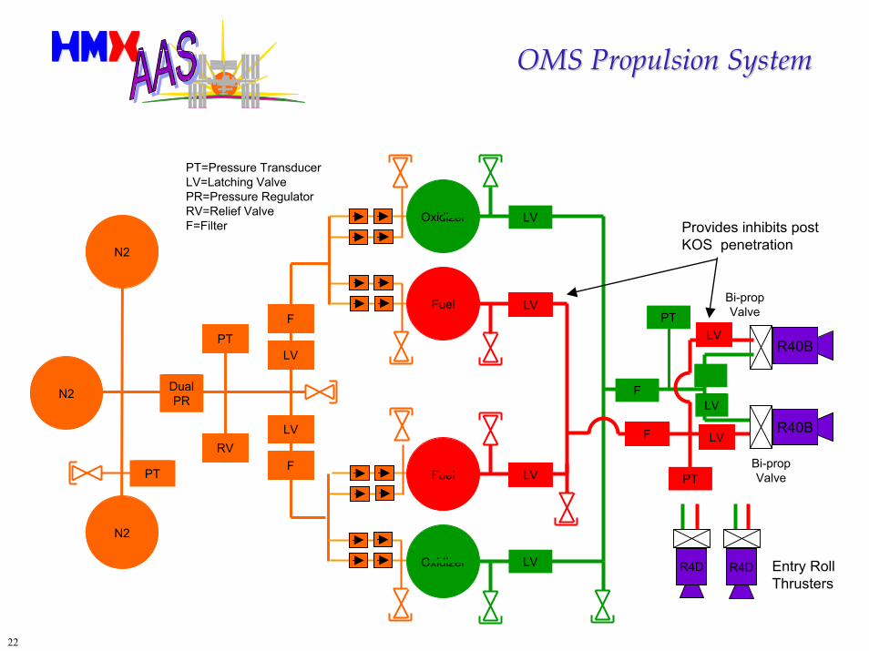
OMS Propulsion SystemOMS Propulsion System
Oxidizer
PT=Pressure Transducer LV=Latching Valve PR=Pressure Regulator RV=Relief Valve F=Filter LV
LV
LV
F
F
Fuel
Fuel
Oxidizer
RV
PT
PT
DualPRN2
N2
N2
LV
LV
F R40B
R40B
Provides inhibits post KOS penetration
Bi-prop ValveLV
FLV
PTLV
LV
LV
Bi-prop ValvePT
R4D R4D Entry RollThrusters
23
XV ColdXV Cold--Gas Reaction Control SystemGas Reaction Control System
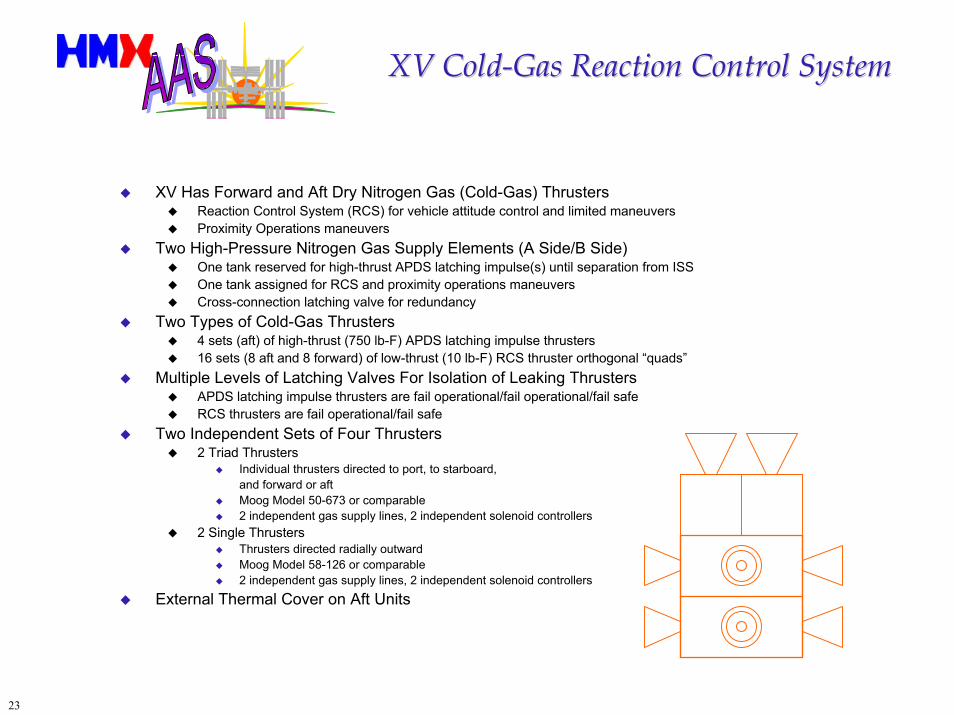
XV Has Forward and Aft Dry Nitrogen Gas (Cold-Gas) ThrustersReaction Control System (RCS) for vehicle attitude control and limited maneuversProximity Operations maneuvers
Two High-Pressure Nitrogen Gas Supply Elements (A Side/B Side)One tank reserved for high-thrust APDS latching impulse(s) until separation from ISSOne tank assigned for RCS and proximity operations maneuversCross-connection latching valve for redundancy
Two Types of Cold-Gas Thrusters4 sets (aft) of high-thrust (750 lb-F) APDS latching impulse thrusters 16 sets (8 aft and 8 forward) of low-thrust (10 lb-F) RCS thruster orthogonal “quads”
Multiple Levels of Latching Valves For Isolation of Leaking ThrustersAPDS latching impulse thrusters are fail operational/fail operational/fail safeRCS thrusters are fail operational/fail safe
Two Independent Sets of Four Thrusters2 Triad Thrusters
Individual thrusters directed to port, to starboard, and forward or aftMoog Model 50-673 or comparable2 independent gas supply lines, 2 independent solenoid controllers
2 Single ThrustersThrusters directed radially outwardMoog Model 58-126 or comparable2 independent gas supply lines, 2 independent solenoid controllers
External Thermal Cover on Aft Units
24
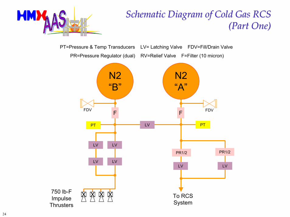
Schematic Diagram of Cold Gas RCSSchematic Diagram of Cold Gas RCS(Part One)
LV
(Part One)
PT=Pressure & Temp Transducers LV= Latching Valve FDV=Fill/Drain Valve
PR=Pressure Regulator (dual) RV=Relief Valve F=Filter (10 micron)
N2“B”
N2“A”
FDV FDVF F
PTPT
LVLV
PR1/2PR1/2
LVLVLVLV
XXXX750 lb-FImpulse
ThrustersTo RCSSystem
25
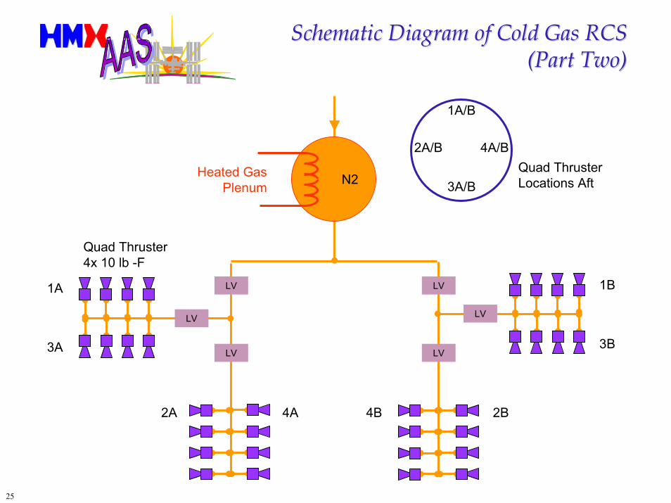
Schematic Diagram of Cold Gas RCSSchematic Diagram of Cold Gas RCS(Part Two)(Part Two)
2A/B 4A/B
1A/B
3A/BHeated Gas
PlenumQuad ThrusterLocations AftN2
Quad Thruster4x 10 lb -F
LV
1B
LV
1A LV LV
3B3A LV LV
2A 4A 4B 2B
26
Reaction Control System ReliabilityReaction Control System Reliability
Potential RCS Failure ModesThruster Stuck-on - worse case, can cause XV to spin up or change velocity, must quickly shut down gas supply to thruster using up-stream valveThruster Leakage - can deplete RCS gas supply, identify by pressure drop in isolated gas supply manifold and isolate using up-stream valveThruster Stuck-off - thruster does not operate when commandedLatching Valve Stuck-on - may prevent isolation of leaking or stuck-on failed thrusterLatching Valve Stuck-off - may isolate and cut off the gas supply to working thrusters
Cold-gas Thrusters Controlled By Solenoid ValvesSimple, highly reliable devicesMechanical failure modes include foreign objects jamming the valve, galling, and wear
Predicted RCS Thruster ReliabilityCycle-life > 5,000 on-off operating cyclesMean Time Between Failures (MTBF): 116,850 hours (estimated)
Comparable application in launch/spaceflight environmentMTBF for worst-case failure, valve stuck-onSource: Moog Space Products Division (10/18/2000)MTBF based on analysis of flight performance & ground testing
27
RCS Thruster Plume ImpingementRCS Thruster Plume Impingement
XV Reaction Control System Uses Cold GasDry Nitrogen Gas Stored In Pressurized TanksFilters Built Into RCS System to Trap Entrained Particles & Droplets
Baseline XV RCS ThrusterActuated by solenoid valveRapid open & close times < 5 millisecondsThrust = 10 lbf
Thruster Plume Contamination EffectsContamination is negligible; dry nitrogen used to protect many sensitive systemNo condensing volatiles or particulates in cold-gas plume
Thruster Plume Impingement EffectsNo plume heating effects; plume is actually cool from gas expansionImpingement forces are less than half of Shuttle vernier RCS thrustersMapping of plume impingement forces planned using NASA JSC SFPLIMP softwareOption to reduce thrust of ISS-facing RCS thrusters on forward (APDS) end of XV
28
Thermal Protection SystemThermal Protection System
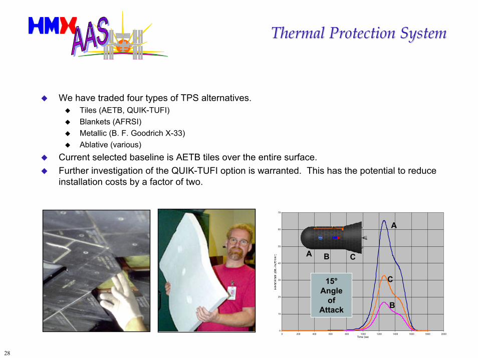
We have traded four types of TPS alternatives.Tiles (AETB, QUIK-TUFI)Blankets (AFRSI)Metallic (B. F. Goodrich X-33)Ablative (various)
Current selected baseline is AETB tiles over the entire surface.Further investigation of the QUIK-TUFI option is warranted. This has the potential to reduce installation costs by a factor of two.
0
10
20
30
40
50
60
70
0 200 400 600 800 1000 1200 1400 1600 1800 2000Time (sec
15° Angle
of Attack
C
B
A
A
B C
29
Details of Thermal Control SubsystemDetails of Thermal Control Subsystem
XV External SurfacesXV Nose, Barrel, and Flare sections covered with rigid ceramic tiles
Baseline is NASA Ames TUFI/AETB-12 rigid tileAbsorptance: 0.90Emissivity: 0.85 to 0.90
XV Boat-tail covered with metallic heat shield and blanketsStainless steel used for thermal modeling purposesAbsorptance: 0.47Emissivity: 0.17
Fixed Radiator on XV base is a currently plannedLoop heat pipes to cool XV avionics and payload compartment
XV Payload CompartmentPressurized with air at ISS standard atmospheric pressureInsulated from XV external surfaces
XV Propulsion SystemInsulated from XV external surfacesHeaters on liquid propellant tanks and bipropellant thruster valves
30
Environmental Control for XVEnvironmental Control for XV
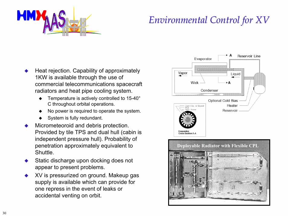
Heat rejection. Capability of approximately 1KW is available through the use of commercial telecommunications spacecraft radiators and heat pipe cooling system.
Temperature is actively controlled to 15-40° C throughout orbital operations.No power is required to operate the system. System is fully redundant.
Micrometeoroid and debris protection. Provided by tile TPS and dual hull (cabin is independent pressure hull). Probability of penetration approximately equivalent to Shuttle.Static discharge upon docking does not appear to present problems. XV is pressurized on ground. Makeup gas supply is available which can provide for one repress in the event of leaks or accidental venting on orbit.
Deployable Radiator with Flexible CPL
31
Several Landing Sites Are Available;Several Landing Sites Are Available;Low Risk Landing System EmployedLow Risk Landing System Employed
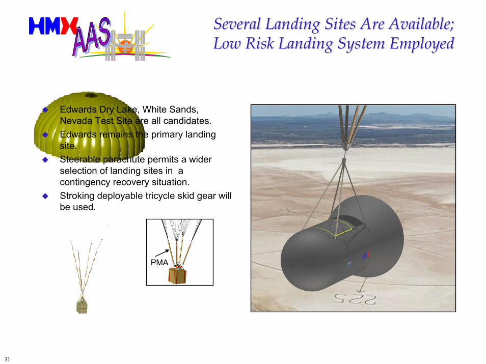
PMA
Edwards Dry Lake, White Sands, Nevada Test Site are all candidates.Edwards remains the primary landing site.Steerable parachute permits a wider selection of landing sites in a contingency recovery situation.Stroking deployable tricycle skid gear will be used.
32
Mass Budget for XVMass Budget for XV
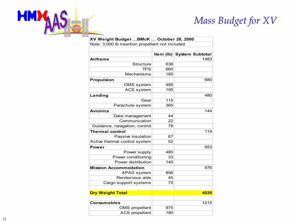
XV Weight Budget …BMcK … October 28, 2000Note: 3,000 lb insertion propellant not included.
Item (lb) System SubtotalAirframe 1483
Structure 638TPS 660
Mechanisms 185Propulsion 680
OMS system 485ACS system 195
Landing 480Gear 115
Parachute system 365Avionics 144
Data management 44Communication 22
Guidance, navigation, control 78Thermal control 119
Passive insulation 67Active thermal control system 52Power 653
Power supply 480Power conditioning 33Power distribution 140
Mission Accommodation 976APAS system 856
Rendezvous aids 45Cargo support systems 75
Dry Weight Total 4535
Consumables 1215OMS propellant 975ACS propellant 180
33
Launch Vehicle SelectionLaunch Vehicle Selection
Currently projected mission model doesn’t justify development of a new launch vehicle.Proven commercial expendables are either not capable of delivering the required load, or they have operational or cost limitations.
Planned production rate of currently produced launch vehicles won’t support XV flight requirements in addition to existing commitments.Available launch facilities for these existing boosters cannot support XV flight requirements in parallel with existing obligations.
Conflicting launch schedules.Launch on demand after short call-up.
HMX concludes that an un-utilized existing booster is the best option for initial XV operations.Follow-on development of a new booster is justified only if XV flight rate increases beyond currently projected model.
34
Near Term Launch OptionNear Term Launch Option
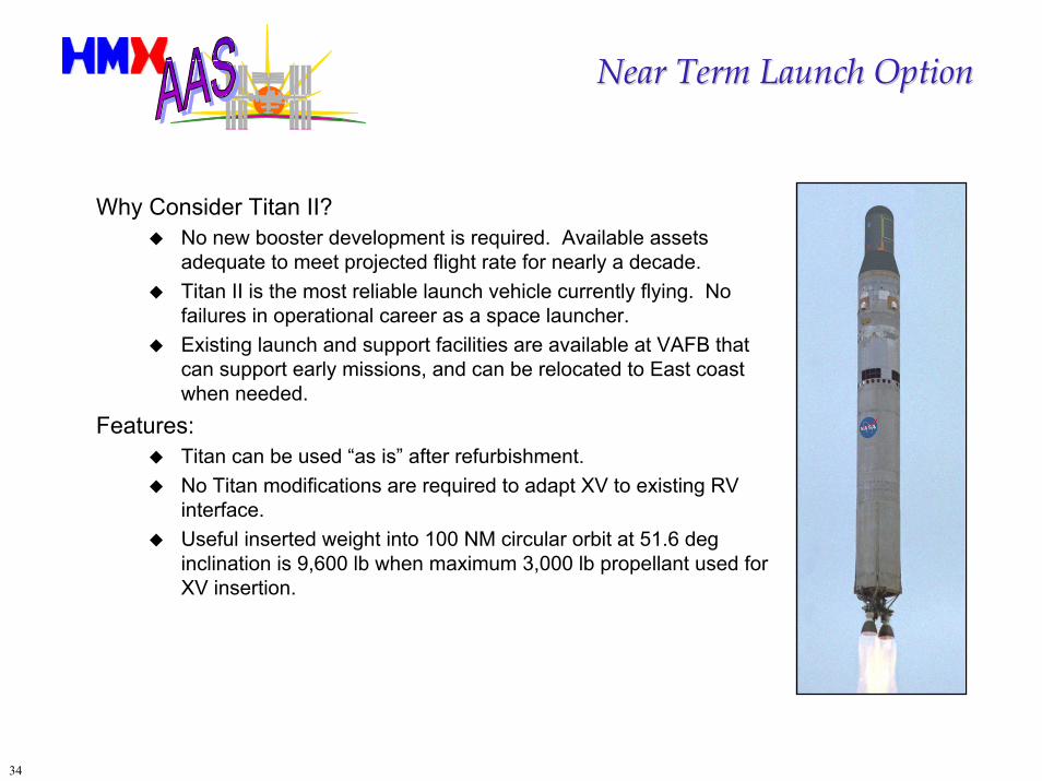
Why Consider Titan II?No new booster development is required. Available assets adequate to meet projected flight rate for nearly a decade.Titan II is the most reliable launch vehicle currently flying. No failures in operational career as a space launcher.Existing launch and support facilities are available at VAFB that can support early missions, and can be relocated to East coast when needed.
Features:Titan can be used “as is” after refurbishment.No Titan modifications are required to adapt XV to existing RV interface.Useful inserted weight into 100 NM circular orbit at 51.6 deg inclination is 9,600 lb when maximum 3,000 lb propellant used for XV insertion.
35
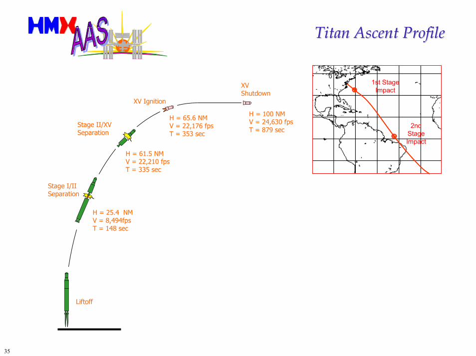
Titan Ascent ProfileTitan Ascent Profile
2nd Stage Impact
1st Stage Impact
XV Shutdown
Liftoff
Stage I/II Separation
H = 25.4 NMV = 8,494fpsT = 148 sec
H = 61.5 NMV = 22,210 fpsT = 335 sec
XV Ignition
H = 65.6 NMV = 22,176 fpsT = 353 sec
H = 100 NMV = 24,630 fpsT = 879 sec
Stage II/XV Separation
36
Advantages of HMX Near Term OptionAdvantages of HMX Near Term Option
No new technology development.Proven 100% successful space launch vehicle that can be available in the time frame of interest without significant risk.Launch facilities and trained support crew available.Sufficient vehicle hardware exists to support ISS operations for at least a decade, leaving significant margin for the development of Future Option vehicle.Proven subsystems in refurbishable XV:
Avionics already qualified from multiple sourcesSoftware solutions available from multiple sourcesDocking Hardware is standard and qualifiedAR&C subsystem elements demonstrated but require validationConventional thermal protection, proven re-entry flight dynamicsOMS Propulsion uses off-the-shelf thrustersRCS (Cold Gas Propulsion) uses proven componentsParachutes already qualified from multiple sources
Fully commercial procurement, fixed price, with a current estimated ROM cost of about $35 million/flight.
37
Titan II ICBM RefurbishmentTitan II ICBM Refurbishmentfor the AAS Missionfor the AAS Mission
Tanks have already been inspected and mapped by USAF. Engines need inspection, replacement of seals and (possibly) turbine rotors, new start cartridges and new dual redundant pressure sensors. A linear shaped charge range safety destruct device must be installed on each stage. (Range Safety Receivers and antennas will be on the XV.)New second stage nozzle skirts may be required.The booster hydraulic units must be serviced.Pre-valves must be replaced.New cabling will be installed as required.Stages need livery repainted as required.No modifications to forward structure are required beyond minor fittings to hold cables transitioning from the XV to the second stage. XV attaches to warhead mount with transition adapter.
38
OnOn--Pad “Storage” of Titan II BoosterPad “Storage” of Titan II BoosterSupporting Launch on <1 Week NoticeSupporting Launch on <1 Week Notice
The Titan can potentially be “stored” ready-to-fly on the pad for several years. Titan II readiness requirement in the silo was a 60 second launch from command. Gemini XI flew with a 2 second launch window to achieve a first orbit rendezvous and dock.
AAS requirement is more relaxed (due to phasing issues) to attain rendezvous with ISS. Current requirement for the light mission is 1 week, and the contractor is asked to suggest the call-up requirement for the heavy mission.HMX concludes that the booster can be ready to fly with about 24-30 hours of notification of a required launch time for either the light or heavy mission.
After launch window delay, the principal preparation delay will be mustering of launch crews, propellant tanking (requires about four hours) and transportation plus loading of contingency cargo.
The ranges will be able to support aggressive launch campaigns with some additional training and preparation of documentation in advance of the mission. This is not an infrastructure or technology issueHMX proposes to pre-stack the booster which would remain un-fueled, with a fueled XV stored in a payload preparation area at the launch site. Upon call up, the XV will be loaded with cargo, a weight & balance performed, and then it will be towed to the pad and immediately mated to the booster. Only three electrical connections need to be made to mate the XV to the Titan. Electrical continuity checks are made and the vehicle is ready to launch after fueling, which requires about four hours.
39
Cargo IssuesCargo Issues
Contingency cargo presents a new problem. By definition, the size, shape, mass and handling requirements of the cargo are unknown until just before launch.
Cargo mass can range from 300-1000 pounds exclusive of cargo carrier or packing for light mission. Cargo is assumed to be passive.
To mitigate this problem we can attempt to predict what heavier and less damage tolerant contingency cargoes may be required to be flown on the XV. NASA can prepare packaging for these “more likely” missions.
Control moment gyrosComputers and electronics boxesLife support componentsSmall mechanisms and tools
For those mission manifests which are by their very nature unpredictable, the subject of quick and clever packaging needs to be rethought.
Take a lesson from the computer and electronics industry which has developed foam in place packaging with plastic liners to prevent contamination. We would then “pack out” on the XV all the packing material brought up to ISS and use it to support down cargo.Use air-filled plastic bags to cushion components in place of foam. Virtually no weight and nontoxic. “3D bubble pack.”Ballast must be prepared in anticipation of less than full manifest. A variety of ballast weights and attach locations must be preplanned.
Launch environment for the XV is approximately +6.5 G on ascent. Entry G is <2.0 at 10-15° alpha.
40
Down CargoDown Cargo
Down cargo requirement is half the up cargo mass.XV may be able to take full mass down (same as up mass) depending on Cg limits. For light missions it can potentially take down more than it brings up.
Unlike vehicles which are destroyed after reentry burn, the HMX XV returns to earth for reuse.
This offers the opportunity to significantly reduce operational costs as well as improve operational reliability.It also offers the opportunity to return equipment, experiments and other cargo to a safe, soft landing.
Packaging and securing cargo will require special forethought and planning plus ISS crew adherence to packing instructions.
HMX favors use of airbags and straps to secure down cargo.
41
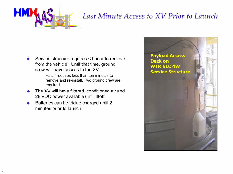
Last Minute Access to XV Prior to LaunchLast Minute Access to XV Prior to Launch
Payload Access Deck on WTR SLC 4WService Structure
Service structure requires <1 hour to remove from the vehicle. Until that time, ground crew will have access to the XV.
Hatch requires less than ten minutes to remove and re-install. Two ground crew are required.
The XV will have filtered, conditioned air and 28 VDC power available until liftoff.Batteries can be trickle charged until 2 minutes prior to launch.
42
Mission Planning to Support Mission Planning to Support Rapid ResponseRapid Response
Since mass and volume of contingency cargo is not known until immediately prior to flight, mission planning must be prepared to:
Perform a weight and balance of cargo upon receipt;Incorporate this data into the ascent and on-orbit software load for the vehicle;Prepare packaging and handling for the cargo if not done in advance;
Launch time to support earliest possible rendezvous must be calculated for optimum launch site and mission timeline must be developed.Contingency crews for pad ops and mission control must be mustered and transported to site(s) and range must be activated.Final vehicle checkout must be accomplished including cargo loading, propellant loading and countdown commencement.
43
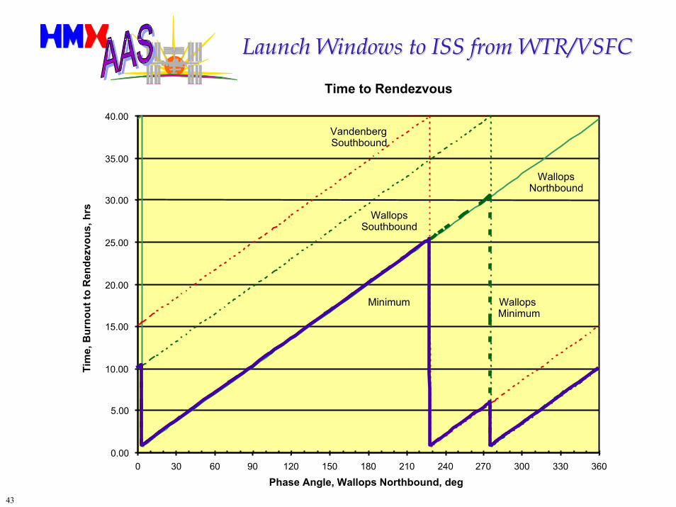
Launch Windows to ISS from WTR/VSFCLaunch Windows to ISS from WTR/VSFC
Time to Rendezvous
WallopsNorthbound
WallopsSouthbound
VandenbergSouthbound
WallopsMinimum
Minimum
0.00
5.00
10.00
15.00
20.00
25.00
30.00
35.00
40.00
0 30 60 90 120 150 180 210 240 270 300 330 360Phase Angle, Wallops Northbound, deg
Tim
e, B
urno
ut to
Ren
dezv
ous,
hrs
44
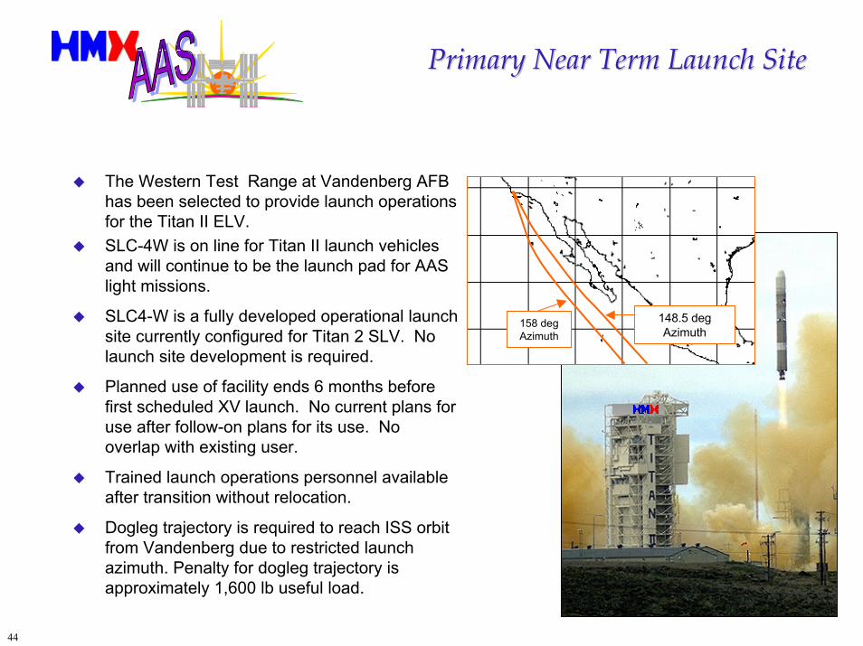
Primary Near Term Launch SitePrimary Near Term Launch Site
The Western Test Range at Vandenberg AFB has been selected to provide launch operations for the Titan II ELV.SLC-4W is on line for Titan II launch vehicles and will continue to be the launch pad for AAS light missions.
SLC4-W is a fully developed operational launch site currently configured for Titan 2 SLV. No launch site development is required.
Planned use of facility ends 6 months before first scheduled XV launch. No current plans for use after follow-on plans for its use. No overlap with existing user.
Trained launch operations personnel available after transition without relocation.
Dogleg trajectory is required to reach ISS orbit from Vandenberg due to restricted launch azimuth. Penalty for dogleg trajectory is approximately 1,600 lb useful load.
148.5 deg Azimuth
158 deg Azimuth
45
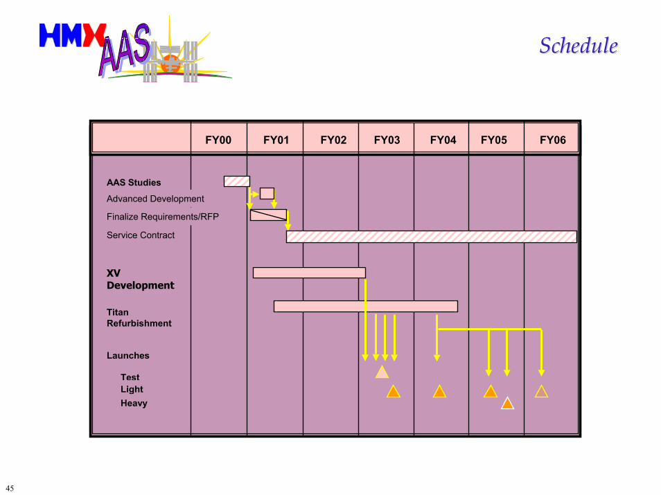
ScheduleSchedule
FY00 FY05FY04FY03FY02FY01 FY06
AAS StudiesAdvanced Development
Finalize Requirements/RFP
Service Contract
XV Development
Titan Refurbishment
Launches
TestLightHeavy
46
Take Away ThoughtsTake Away Thoughts
HMX can deliver contingency cargo to ISS by 2003, for a launch cost of about $35 million. Total program costs for four light launches (1 test, three operational) is about $145 million.HXM can comply fully with all requirements. No substantive change to the requirements is necessary.We are ready with subcontractors to immediately perform risk mitigation activities. We have proven backups to most vendors and components.The Alternate Access mission is largely a program management task and HMX has demonstrated its ability to perform this task.There is very little time to prepare for the first flight; the sooner we get underway the better for NASA and the ISS Program.
Wernher von Braun: "Our two greatest problems are gravity and paperwork. We can lick gravity, but sometimes the paperwork is overwhelming."
47
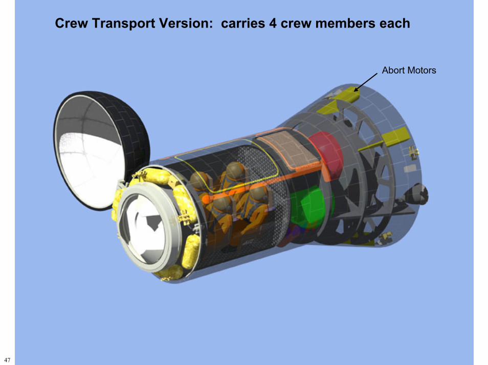
Crew Transport Version: carries 4 crew members each
Abort Motors