Embed Size (px)
Citation preview

SYSTEM 25
SYSTEM 50
SYSTEM 63
SYSTEM 75 A
LSYSTEM
100
ALSIDENT® SYSTEM 75Aluminium (AL)
Product Information


SYSTEM 25
SYSTEM 50
SYSTEM 63
SYSTEM 75 A
LSYSTEM
100
75 AL GI 01UK.08.2014
System 75 – Aluminium – General Information
Copyright© ALSIDENT® SYSTEM 2014. Right reserved for modification of design and measurements.
System 75 – AluminiumAlsident® System 75 – airflow between 80 and 180 m³/h.
System 75 Aluminium is suitable in non-aggressive working environments where there are no special requirements for chemical resistance or antistatic abilities such as laboratories, laser technique, hospitals, chemical-, pharma- ceutical- and food industry, schools and universities, electronics and engineering industries. In addition the System 75 Aluminium is also used in hairdressing saloons to extract vapours and gases from hair-dyeing and permanent waving.
The standard Alsident® System 75 AL extraction arms are available in various types that are complementary to each other with ranges up to 1990 mm. The System 75 AL extraction arms are easily mounted with standard brackets for table, wall or ceiling. In combination with the wide range of hood designs this makes it possible to choose an extraction arm adapted for almost any work situation.
Alsident® System 75 AL extraction arms are self-sustaining with an internal bearing spring, joints of polypropylene (PP) and tubes of anodized aluminium with a diameter of 75 mm. All internal components are of acid-proof stainless steel (AISI 316L). The two longest models for wall and ceiling mounting are available with both internal spring or external gas spring. The construction constitutes a very user-friendly extraction arm which is easy to adjust to the source of the pollutant during the working process.
An extraction arm from Alsident® System consists of three parts: An extraction arm, a hood and a mounting bracket. Each part must be ordered separately.
In addition to the standard range, Alsident® System 75 AL offers special customized solutions. The Alsident® technical department is always ready to help you finding the best solution.
Alsident® offers short delivery time for both standard productions and special solutions.
Product Description
Product Specification

SYSTEM 25
SYSTEM 50
SYSTEM 63
SYSTEM 75 A
LSYSTEM
100
75 AL GI 02UK.08.2014Copyright© ALSIDENT® SYSTEM 2014. Right reserved for modification of design and measurements.
System 75 – Aluminium – Generel Information
Product Specification
Key to the signatures
75
SYSTEM NO. CHAPTER
01
PAGE
GITM
WCM
General Information
Table Mounted
Wall/Ceiling Mounted
VERSION
AL Aluminium
Recommended Airflow: Normal: 140 m3/h
Minimum: 80 m3/h
Maximum: 180 m3/h
Air Temperature: -15 C̊ – +90 C̊
Material: Pipes: Anodized Aluminium (10 µ)
Joints: Polypropylene (PP) – red or white
O-rings: Polyethylene (PE)
Mounting Flanges: Polypropylene (PP) – red or white
Damper: Polypropylene (PP)
Thumbscrew: Polypropylene (PP) – black
Threaded Stay: Acid-proof stainless steel (AISI 316L)
Spring: Acid-proof stainless steel (AISI 316L)
Gas spring1): Steel
1) Avaliable on 75-9065 and 75-9090
Abbr.: PP: Polypropylene Shatterproof and chemical resistant
PE: Polyethylene
PETG: Polyethylene Therephthalat, Glycol-modified Transparent and resistant to solvents
Local Extraction for workplaces incl. all materials for mounting. All components RoHS-compatible according to the directive 2002/95/EF (RoHS).
Technical Specifications
Technical Reports
Technical Reports: Capture Efficiency (Danish Technological Institute)
Download: www.alsident.com > Technical Support > Test Reports

SYSTEM 25
SYSTEM 50
SYSTEM 63
SYSTEM 75 A
LSYSTEM
100
75 AL GI 03
75-55-1-5
75-5545-1-5
UK.08.2014
System 75 – Aluminium – General Information
Copyright© ALSIDENT® SYSTEM 2014. Right reserved for modification of design and measurements.
Table mountedProduct Overview
Table mounted (TM), 2-Joint
Table mounted (TM), 3-Joint
Diam. [mm]
L [mm]
B [mm]
C [mm]
Weight appr. [kgs] Part No.
Colour of jointRed White
75 550 350 450 1.5 75-35-1 -4 -5
75 650 450 450 2.0 75-45-1 -4 -5
75 750 550 450 2.3 75-55-1 -4 -5
Diam. [mm]
L [mm]
A [mm]
B [mm]
C [mm]
Weight appr. [kgs] Part No.
Colour of jointRed White
75 830 350 350 450 1.9 75-3535-1 -4 -5
75 1105 550 450 450 2.5 75-5545-1 -4 -5
75 1290 650 550 450 2.7 75-6555-1 -4 -5
75 1620 900 650 450 3.0 75-9065-1 -4 -5

SYSTEM 25
SYSTEM 50
SYSTEM 63
SYSTEM 75 A
LSYSTEM
100
75 AL GI 04
75-6555-3-5
UK.08.2014
System 75 – Aluminium – General Information
Copyright© ALSIDENT® SYSTEM 2014. Right reserved for modification of design and measurements.
Diam. [mm]
L [mm]
A [mm]
B [mm]
C [mm]
Weight appr. [kgs] Part No.
Colour of jointRed White
75 795 350 350 450 2.0 75-3535-3 -4 -5
75 1200 350 900 450 2.3 75-3590-3 -4 -5
75 1060 550 450 450 2.6 75-5545-3 -4 -5
75 1230 650 550 450 2.8 75-6555-3 -4 -5
75 1550 900 650 450 3.1 75-9065-3 -4 -5
75 1660 900 650 450 3.4 75-9065-3-22* -4 -5
75 1730 900 900 450 3.6 75-9090-3 -4 -5
75 1990 900 900 450 3.8 75-9090-3-22** -4 -5
Wall/Ceiling mounted (WCM), 3-Joint
Wall- and Ceiling MountedProduct Overview
*) With 1 external gas spring **) With 2 external gas springs
Creates a minimum angle between the extraction arm and ceiling column/wall bracket of 90° or 60°. Prevents the extraction arm from touching a suspended ceiling when folded up.
NB! The special stop cannot be retrofitted. It must be ordered with the extraction arm.
Find article No. of Extraction arm with: Stop 60°: Model of Extraction Arm + -60 Stop 90°: Model of Extraction Arm + -90
E.g.: Model 75-9065-3-5 with Stop 60: Art. No. 75-9065-3-5-60
NB! For Special Stop on gas spring: see page GI 07.
Special Stop on Socket Joint

SYSTEM 25
SYSTEM 50
SYSTEM 63
SYSTEM 75 A
LSYSTEM
100
75 AL GI 05UK.08.2014
System 75 – Aluminium – General Information
Copyright© ALSIDENT® SYSTEM 2014. Right reserved for modification of design and measurements.
Recommended when extracting hot gases, fumes, light dust concentrations etc. The powder coated surface improves the durability of the hood.
Material Metal hood: Aluminium (powder coated) Flange: Polypropylene (PP) Connection to tube: Aluminium (anodized – 10 µ)
Recommended when extracting hot gases, fumes, light dust concentrations etc. Suitable for autoclaving.
Material Hood: Aluminium (anodized – 10 µ) Flange: Aluminium (anodized – 10 µ) Connection to tube: Aluminium (anodized – 10 µ)
Accessories Overview
Recommended for concentrated sources of pollution. Efficient as it gets close to the source without obstructing the work process. Often used at soldering processes. Internal duffuser to increase efficiency.
Material Suction Nozzle: Aluminium (anodized – 10 µ) and Polypropylene (PP) Flange: Polypropylene (PP) Connection to tube: Aluminium (anodized – 10 µ)
Metal Hood (diam. 200 mm) Part No.: 1-7524-4 /-5
Metal Hood (diam. 200 mm) Part No.: 1-7524
Suction Nozzle – width 200 mm Part No.: 1-7525-4 /-5
Part No. Red White
1-7524 -4 -5
Part No. Red White
1-7525 -4 -5

SYSTEM 25
SYSTEM 50
SYSTEM 63
SYSTEM 75 A
LSYSTEM
100
75 AL GI 06UK.08.2014
System 75 – Aluminium – General Information
Copyright© ALSIDENT® SYSTEM 2014. Right reserved for modification of design and measurements.
Recommended for small concentrated sources of pol-lution. Efficient as it gets close to the source without obstructing the work process. Tip with funnel of Polypropylene increases the extrac-tion efficiency.
Material Tube: Aluminium (anodized – 10 µ) Tip: Polypropylene (PP)
Recommended for light fumes, gases and small open vessels. The transparent hood assists in keeping a good view of the workpiece. Increased stability due to reinforced rim of the hood. Increased efficiency at an angled position.
Material Hood: PETG Flange: Polypropylene (PP) Connection tube1: Aluminium (anodized – 10 µ)
Suction pen – Alu + Polypropylene (PP) Part No.: 1-7526-4 /-5
Dome Hood (diam. 280 mm) Part No.: 1-7528-4 /-5
Accessories Overview
Recommended for small concentrated sources of pol-lution. Efficient as it gets close to the source without obstructing the work process. Carefully made funnel increases the extraction ef-ficiency.
Material Tube: Aluminium (anodized – 10 µ)
Suction pen – Aluminium Part No.: 1-7525
Part No. Red White
1-7526 -4 -5
Part No. Red White
1-7528 -4 -5
1) Separately enclosed on delivery
Recommended for light fumes, gases and small open vessels. The transparent hood assists in stability due to reinforced rim of the hood. Increased efficiency at an angled position.
Material Hood: PETG Flange: Polypropylene (PP)
Connection tube1: Aluminium (anodized – 10 µ)
Dome Hood (diam. 385 mm) Part No.: 1-7535-4 /-5
Part No. Red White
1-7535 -4 -5
1) Separately enclosed at delivery

SYSTEM 25
SYSTEM 50
SYSTEM 63
SYSTEM 75 A
LSYSTEM
100
75 AL GI 07UK.08.2014
System 75 – Aluminium – General Information
Copyright© ALSIDENT® SYSTEM 2014. Right reserved for modification of design and measurements.
Accessories Overview
Recommended when extracting heavy gases and fumes. High efficiency when placed vertically on a surface e.g. a table. Practical rim for easy positioning of the hood. Gets close to the source without obstructing the work process.
Material Hood: PETG Flange: Polypropylene (PP) Connection tube1: Aluminium (anodized – 10 µ)
Recommended for both light and heavy fumes, gases and for open vessels, as this hood is suited for hori-zontal position above and vertical position behind the source of pollution. Good efficiency when placed vertically on a surface e.g. a table. Increased stability due to reinforced rim of the hood. The transparent hood assists in keeping a good view of the workpiece.Material Hood: PETG Flange: Polypropylene (PP) Connection tube1: Aluminium (anodized – 10 µ)
Flat Hood (330 x 240 mm) Part No.: 1-753324-4 /-5
Square Hood (420 x 320 mm) Part No.: 1-754232-4 /-5
Protective Grill for mounting in hood. Prevents extraction of foreign materials.
Material: Polypropylene (PP) Colour: White
Protective Grill (for hoods) Part No.: 5-17
Can be mounted on models with an external gas spring. Prevents the extraction arm from touching a suspended ceiling when folded up. The stop for gas spring can be retrofitted and placed individually on the gas spring.
Part No. Red White
1-753324 -4 -51) Separately enclosed at delivery
Part No. Red White
1-754232 -4 -51) Separately enclosed at delivery
Special Stop for Gas Spring Part No.: 7-100-1

SYSTEM 25
SYSTEM 50
SYSTEM 63
SYSTEM 75 A
LSYSTEM
100
75 AL GI 08UK.08.2014
System 75 – Aluminium – General Information
Copyright© ALSIDENT® SYSTEM 2014. Right reserved for modification of design and measurements.
Colour of flange Part No.
Red 30-75-5-4
White 30-75-5-5
Accessories Overview
Used to mount System 75 Table Mounted Extraction Arms on table side which makes it removable for mobile installations. Made of white polyester powder coated steel.
Other colours available on request.
Wall bracket Part Nos.: 2-195 & 2-195-10-5 & 2-195-050
Table bracket Part No.: 2-7510
Reducers Part No.: 4-8075 & 4-10075
U-profile Part No.: 30-75-5-4 /-5-5
Used to connect System 75 Extraction Arms or Wall Bracket 2-195 to duct. Made of white Polypropylene (PP).
Reducing from/to [mm] Note White
80/75 From extraction arm to duct 4-8075
100/75 From wall bracket or extraction arm to duct Ø100 4-10075
Colour Open sides Closed sides
White 2-195 2-195-10-5
Black 2-195-050 -
For wall mounting of System 50 Extraction arms. Made of steel with a polyester powder coating in white or black on all surfaces. Other colours available on request.
Three options available for the connection to the duct:
1) Directly from the top of the bracket to a Ø 80 mm spiro duct.2) With reducer 4-10075 to a Ø 100 mm spiro duct
(reducer included).3) Directly from the top of the bracket to a Ø 75 alu tube.
Used for reinforcement of the socket pipe when table mounting a System 75 extraction arm in table plate. Made of steel with a white polyester powder coated surface and an extra flange. The flange is available in white or red. Other colours for the U-profile are available on request.

SYSTEM 25
SYSTEM 50
SYSTEM 63
SYSTEM 75 A
LSYSTEM
100
75 AL GI 09UK.08.2014
System 75 – Aluminium – General Information
Copyright© ALSIDENT® SYSTEM 2014. Right reserved for modification of design and measurements.
Accessories Overview
Used for mounting the System 75 Ceiling Mounted Extraction Arms. The ceiling column is made of white polyester powder coated steel. Available in two models with side connection or top connection to duct.
For standard lengths see below.
Other lengths, colours and acidproof stainless steel available on request.
Connection Diameter: With top connection: max. 100 mm With side connection: 80 mm
Ceiling Columns
Length [mm] Weight app. [kg] White Black White Black
250 2.0 2-250-20 2-250-050-20 - -
500 3.0 2-500-20 2-500-050-20 2-500-80 2-500-050-80
750 3.8 2-750-20 2-750-050-20 2-750-80 2-750-050-80
1000 4.5 2-1000-20 2-1000-050-20 2-1000-80 2-1000-050-80
1250 5.4 2-1250-20 - * 2-1250-80 - *
1500 6.1 2-1500-20 - * 2-1500-80 - *
1750 7.1 2-1750-20 - * 2-1750-80 - *
2000 7.9 2-2000-20 - * 2-2000-80 - *
2500 9.4 2-2500-20* - * 2-2500-80* - *
Side connectionTop connection
*) Availble on request
Ceiling Columns
Support Bracket for long ceiling column Part No.: 2-75-5
For extra support of long ceiling columns.
For support with wire to deck or by fastening to ceiling rail system.
The support bracket is made of steel with a white polyester powder-coating. Other colours available on request.
Dimensions Internal: 100 x 100 mm External: 200 x 200 mm
Cover Flange Part No.: 4-200-200
Made to cover the perforation through a concealed ceiling. To be glued on to the concealed ceiling around the ceiling column.
Dimensions Internal: 100 x 100 mm External: 200 x 200 mm

SYSTEM 25
SYSTEM 50
SYSTEM 63
SYSTEM 75 A
LSYSTEM
100
75 AL GI 010
C D
GI 10GI 10UK.08.2014
System 75 – Aluminium – General Information
Copyright© ALSIDENT® SYSTEM 2014. Right reserved for modification of design and measurements.
Technical DescriptionC
C
D
D
Syst
em 7
5, T
able
mou
nted
Syst
em 7
5, W
all-
and
Ceili
ng m
ount
ed
Tested by Danish Technological Institute
Pressure Drop Chart

SYSTEM 25
SYSTEM 50
SYSTEM 63
SYSTEM 75 A
LSYSTEM
100
75 AL GI 11
1.1 5
1.4 3
1.3
2.1
4
6
1
5 2
1.5
1.2
UK.08.2014
System 75 – Aluminium – General Information
Copyright© ALSIDENT® SYSTEM 2014. Right reserved for modification of design and measurements.
Spare Parts List
Joint with Damper 4-75-4 /-5
Joint with damper
Pos. Product No.
A 4-75-4 /-5A
Pos. Spare part No. Red White Description A
1 4-7512 -4 -5 Joint, 12 mm 1
1.1 5-75 Teflon Washer 1
1.2 5-75-4 Thumbscrew, 4 mm 1
1.3 5-5075 Wing for Damper 1
1.4 800-4-75 Damper 1
1.5 5-12-411 Seegerring 1
2 4-755-0 -4 -5 Joint, 5 mm 1
2.1 5-75-4 Thumbscrew, 4 mm 1
3 5-100-6 O-Ring 1
4 5-75 Teflon Washer 1
5 5-75-5 Thumbscrew, 5 mm 2
6 5-75-5-221 Threaded Stay 1
When ordering spare parts pos. 1 or 2 the underlying spare parts (pos 1.1 - 1.5 or 2.1) are included.
[pieces applied]

SYSTEM 25
SYSTEM 50
SYSTEM 63
SYSTEM 75 A
LSYSTEM
100
75 AL
A: Model 75-35-1-4 /-5 R: 550 mmB: Model 75-45-1-4 /-5 R: 650 mmC: Model 75-55-1-4 /-5 R: 750 mmD: Model 75-3535-1-4 /-5 R: 830mmE: Model 75-5545-1-4 /-5 R: 1105 mmF: Model 75-6555-1-4 /-5 R: 1290mmG: Model 75-9065-1-4 /-5 R: 1620 mm
UK.08.2014Copyright© ALSIDENT® SYSTEM 2014. Right reserved for modification of design and measurements.
System 75 – Aluminium – Table Mounted (TM)
TM 01
Working Area
Note: The working area of the arm is defined from the center of the opening of the accessory. The working area changes according to type of accessory and positioning. When choosing the arm we recommend that the stationary working position of the accessory is not placed in the highest or lowest part of the working area.
(All measurements in mm)
Accessory: Suction pen Nr. 1-7525
Table mounted with Suction pen
SYSTEM 25
SYSTEM 50
SYSTEM 63
SYSTEM 75 A
LSYSTEM
100
75 ALUK.08.2014Copyright© ALSIDENT® SYSTEM 2014. Right reserved for modification of design and measurements.
System 75 – Aluminium – Table Mounted (TM)
TM 02
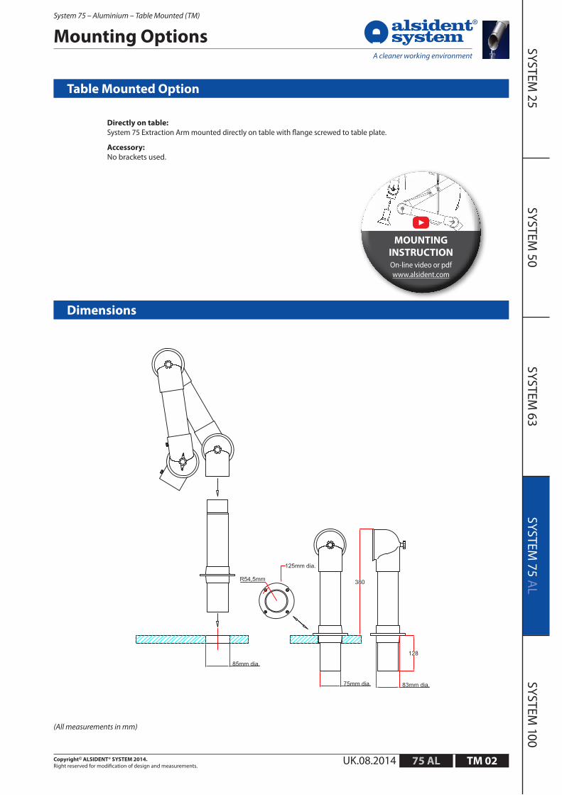
Mounting Options
Directly on table:System 75 Extraction Arm mounted directly on table with flange screwed to table plate.
Accessory:No brackets used.
Table Mounted Option
(All measurements in mm)
Dimensions
On-line video or pdf www.alsident.com
MOUNTING INSTRUCTION

SYSTEM 25
SYSTEM 50
SYSTEM 63
SYSTEM 75 A
LSYSTEM
100
75 ALUK.08.2014Copyright© ALSIDENT® SYSTEM 2014. Right reserved for modification of design and measurements.
System 75 – Aluminium – Table Mounted (TM)
TM 03
Mounting Options
(All measurements in mm)
With table bracketSystem 75 Extraction Arm mounted on table side with a table bracket.
Very functional option when impossible to mount directly on table or when a mobile installation is required.
Accessory:Table Bracket, Part No.: 2-7510
Table Mounted Option with Table Bracket
Dimensions
On-line video or pdf www.alsident.com
MOUNTING INSTRUCTION

SYSTEM 25
SYSTEM 50
SYSTEM 63
SYSTEM 75 A
LSYSTEM
100
75 ALUK.08.2014Copyright© ALSIDENT® SYSTEM 2014. Right reserved for modification of design and measurements.
System 75 – Aluminium – Table Mounted (TM)
TM 04
Technical DescriptionTable Bracket
Part No.: 2-7510
Dimensions
(All measurements in mm)
Used to mount System 75 Table Mounted Arms on table side. Removable for mobile installations. Made of white Polyester powder coated steel.
Other colours available on request.

SYSTEM 25
SYSTEM 50
SYSTEM 63
SYSTEM 75 A
LSYSTEM
100
75 ALUK.08.2014Copyright© ALSIDENT® SYSTEM 2014. Right reserved for modification of design and measurements.
System 75 – Aluminium – Table Mounted (TM)
TM 05
Mounting Options
U-profile above table System 75 Extraction Arm mounted in table with U-profile above table.
Accessory U-profile, Part No.: 30-75-5-4 /-5
Mounting Instruction
1. Make a hole in the table with a max. diameter of 85 mm. Mount the socket pipe on the table with the included screws.
2. Place the U-profile on the socket pipe and fasten it to the table.
3. Place the extra flange on the socket pipe and fasten it to the U-profile with the included screws.
4. Place the extraction arm on the socket pipe. Make sure the internal spring goes into the socket pipe.
5. Follow the mounting instructions for the extraction arm.
Table mounted option with U-profile above table
Dimensioner
On-line video or pdf www.alsident.com
MOUNTING INSTRUCTION
(All measurements in mm)

SYSTEM 25
SYSTEM 50
SYSTEM 63
SYSTEM 75 A
LSYSTEM
100
75 ALUK.08.2014Copyright© ALSIDENT® SYSTEM 2014. Right reserved for modification of design and measurements.
System 75 – Aluminium – Table Mounted (TM)
TM 06
Mounting Options
U-profile under table System 75 Extraction Arm mounted in table with U-profile below table.
Accessory U-profile, Part No.: 30-75-5-4 /-5
Mounting Instruction
1. Make a hole in the table with a max. diameter of 85 mm. Mount the socket pipe on the U-profile with the included screws.
2. Place the U-profile with the socket pipe on the table and fasten it.
3. Place the extra flange on the socket pipe and fasten it to the table with the included screws.
4. Place the extraction arm on the socket pipe. Make sure the internal spring goes into the socket pipe.
5. Follow the mounting instructions for the extraction arm.
Table mounted option with U-profile under table
Dimensions
On-line video or pdf www.alsident.com
MOUNTING INSTRUCTION
(All measurements in mm)

SYSTEM 25
SYSTEM 50
SYSTEM 63
SYSTEM 75 A
LSYSTEM
100
75 ALUK.08.2014Copyright© ALSIDENT® SYSTEM 2014. Right reserved for modification of design and measurements.
System 75 – Aluminium – Table Mounted (TM)
TM 07
Technical DescriptionU-profile
Part Nos.: 30-75-5-4 /-5
Dimensions
Used for reinforcement of the socket pipe when table mounting a System 75 extraction arm in table plate. The U-profile can be placed both above an below the table.Made of steel with a white powder coated surface and an extra flange. The flange is available in white or red. Other colours for the U-profile is available on request.
(All measurements in mm)
Colour of flange Part No.
Red PP 30-75-5-4
White PP 30-75-5-5

SYSTEM 25
SYSTEM 50
SYSTEM 63
SYSTEM 75 A
LSYSTEM
100
75 AL
9 3 2
8 6
1 10 5 (5a)
7
3
6 7 6
5 7
7
6
4
6 7 2 3 4
1 9
7 6 5
(A) 75-35-1 (B) 75-45-1 (C) 75-55-1
(D) 75-3535-1 (E) 75-5545-1 (F) 75-6555-1 (G) 75-9065-1
UK.08.2014Copyright© ALSIDENT® SYSTEM 2014. Right reserved for modification of design and measurements.
System 75 – Aluminium – Table Mounted (TM)
TM 08
Spare Parts List – see next page
Spare Parts

SYSTEM 25
SYSTEM 50
SYSTEM 63
SYSTEM 75 A
LSYSTEM
100
75 ALUK.08.2014Copyright© ALSIDENT® SYSTEM 2014. Right reserved for modification of design and measurements.
System 75 – Aluminium – Table Mounted (TM)
TM 09
Spare Parts List
Pos. Product No. Red White Joint
A 75-35-1 -4 -5 2-Joint
B 75-45-1 -4 -5 2-Joint
C 75-55-1 -4 -5 2-Joint
D 75-3535-1 -4 -5 3-Joint
E 75-5545-1 -4 -5 3-Joint
F 75-6555-1 -4 -5 3-Joint
G 75-9065-1 -4 -5 3-Joint
A
B
C
D
E
F
G
*) Spare Parts List for Joint with Damper – see General Information
Pos. Part No. Description A B C D E F G
1 3-7540-1-4 /-5 C-pipe TM 400 1 1 1 1 1 1 1
2 5-75-2-4-01 Spring 4 mm (2-Joint) 1 1
2 5-75-3-4-01 Spring 4 mm 1
2 5-75-3-5-01 Spring 5 mm 1 1
2 5-75-3-6-01 Spring 6 mm 1
3 5-100-6 O-ring 1 1 1 2 2 2 2
4 3-7535-9-4 /-5 B-pipe 350 1 1
4 3-7545-9-4 /-5 B-pipe 450 1 1
4 3-7555-9-4 /-5 B-pipe 550 1 1
4 3-7565-9-4 /-5 B-pipe 650 1
5 5-75-5-211 Threaded Stay 1 1 1 2 2 2 1
5a 5-75-8-210 Threaded Stay, 8 mm 1
6 5-75-5 Thumbscrew, 5 mm 2 2 2 4 4 4 4
7 5-75 Teflon Washer 2 2 2 4 4 4 4
8 3-7535-8-4 /-5 A-pipe 350 1
8 3-7555-8-4 /-5 A-pipe 550 1
8 3-7565-8-4 /-5 A-pipe 650 1
8 3-7590-8-4 /-5 A-pipe 900 1
9 4-75-4 /-5 Joint with damper* 1 1 1 1 1 1 1
10 4-755-4 /-5 Joint Ø5 1 1 1 1 1 1 1
[pieces applied]
When ordering spare parts please quote:
Product No. e.g.: 75-55-1-5 (white) Description - B-pipe 550 Part No. - 3-7555-9-5 Quantity - 1 pc.
If you wish to customize the arm with a spare part which is not a constituent part of the particular model, please contact your Alsident dealer.

SYSTEM 25
SYSTEM 50
SYSTEM 63
SYSTEM 75 A
LSYSTEM
100
75 AL
A: Model 75-3535-3-4 /-5 R: 745 mmB: Model 75-3590-3-4 /-5 R: 1200 mmC: Model 75-5545-3-4 /-5 R: 1060 mmD: Model 75-6555-3-4 /-5 R: 1230mmE: Model 75-9065-3-4 /-5 R: 1550 mmF: Model 75-9065-3-22-4 /-5 R: 1660 mmG: Model 75-9090-3-4 /-5 R: 1730 mmH: Model 75-9090-3-22-4 /-5 R:1990 mm
UK.08.2014Copyright© ALSIDENT® SYSTEM 2014. Right reserved for modification of design and measurements.
System 75 – Aluminium – Wall/Ceiling Mounted (WCM)
WCM 01
Tilbehør: Sugespids Nr. 1-7525A: Model 75-3535-3-4 /-5 R: 745 mmB: Model 75-3590-3-4 /-5 R: 1200 mmC: Model 75-5545-3-4 /-5 R: 1060 mmD: Model 75-6555-3-4 /-5 R: 1230mmE: Model 75-9065-3-4 /-5 R: 1550 mmF: Model 75-9065-3-22-4 /-5 R: 1660 mmG: Model 75-9090-3-4 /-5 R: 1730 mmH: Model 75-9090-3-22-4 /-5 R:1990 mm
Working AreaWall Mounted with Suction pen
Note:The working area of the arm is defined from the center of the opening of the accessory. The working area changes according to type of accessory and positioning. When choosing the arm we recommend that the stationary working position of the accessory is not placed in the highest or lowest part of the working area.
(All measurements in mm)
Accessory: Suction pen Nr. 1-7525

SYSTEM 25
SYSTEM 50
SYSTEM 63
SYSTEM 75 A
LSYSTEM
100
75 ALUK.08.2014Copyright© ALSIDENT® SYSTEM 2014. Right reserved for modification of design and measurements.
System 75 – Aluminium – Wall/Ceiling Mounted (WCM)
WCM 02
Mounting Options
(All measurements in mm)
Wall Mounted System 75 Extraction Arm – with wall bracket
Accessory: Wall bracket, Part No.: 2-195
Wall Mounted Option
Dimensions
On-line video or pdf www.alsident.com
MOUNTING INSTRUCTION

SYSTEM 25
SYSTEM 50
SYSTEM 63
SYSTEM 75 A
LSYSTEM
100
75 AL
Artikelnr.: 2-195 und 2-195-10-5
*)
UK.08.2014Copyright© ALSIDENT® SYSTEM 2014. Right reserved for modification of design and measurements.
System 75 – Aluminium – Wall/Ceiling Mounted (WCM)
WCM 03
Technical DescriptionWall Bracket
Part Nos.: 2-195 and 2-195-10-5
Dimensions
(All measurements in mm)
For wall mounting of System 75 Extraction arms. Made of steel with a polyester powder coating in white or black on all surfaces. Other colours available on request.
Three options available for the connection to the duct:
1) Directly from the top of the bracket to a Ø 80 mm spiro duct.
2) With reducer 4-10075 to a Ø 100 mm spiro duct (reducer included).
3) Directly from the top of the bracket to a Ø 75 alu tube.
Colour Open sides Closed sides
White 2-195 2-195-10-5*
Black 2-195-050 -
*) The wall bracket with the sides closed is suitable for applications with extreme requirements to cleaning.

SYSTEM 25
SYSTEM 50
SYSTEM 63
SYSTEM 75 A
LSYSTEM
100
75 AL
A: Model 75-3535-3-4 /-5 R: 795 mmB: Model 75-3590-3-4 /-5 R: 1200 mmC: Model 75-5545-3-4 /-5 R: 1060 mmD: Model 75-6555-3-4 /-5 R: 1230 mmE: Model 75-9065-3-4 /-5 R: 1550 mmF: Model 75-9065-3-22-4 /-5 R: 1660 mmG: Model 75-9090-3-4 /-5 R: 1730 mmH: Model 75-9090-3-22-4 /-5 R: 1990 mm
UK.08.2014Copyright© ALSIDENT® SYSTEM 2014. Right reserved for modification of design and measurements.
System 75 – Aluminium – Wall/Ceiling Mounted (WCM)
WCM 04
Accessory: Suction pen Part No. 1-7525-7-5
Working AreaCeiling Mounted with Suction pen
Note:The working area of the arm is defined from the center of the opening of the accessory. The working area changes according to type of accessory and positioning. When choosing the arm we recommend that the stationary working position of the accessory is not placed in the highest or lowest part of the working area.
(All measurements in mm)

SYSTEM 25
SYSTEM 50
SYSTEM 63
SYSTEM 75 A
LSYSTEM
100
75 ALUK.08.2014Copyright© ALSIDENT® SYSTEM 2014. Right reserved for modification of design and measurements.
System 75 – Aluminium – Wall/Ceiling Mounted (WCM)
WCM 05
Mounting Options
(All measurements in mm)
Ceiling Mounted System 75 Extraction Arm in a ceiling column with side connection.
Accessory: Ceiling Column, Part No. depending on lengths.
Ceiling Mounted Option
Dimensions
On-line video or pdf www.alsident.com
MOUNTING INSTRUCTION

SYSTEM 25
SYSTEM 50
SYSTEM 63
SYSTEM 75 A
LSYSTEM
100
75 ALUK.08.2014Copyright© ALSIDENT® SYSTEM 2014. Right reserved for modification of design and measurements.
System 75 – Aluminium – Wall/Ceiling Mounted (WCM)
WCM 06
Technical DescriptionCeiling Column
Used for mounting the System 75 Ceiling Mounted Extraction Arms. The ceiling column is made of steel with a white or black polyester powder coating. Available in two models with side connection or top connection to duct. For standard lengths see below.
Other lengths, colours or acid-proof stainless steel (AISI 316L) available on request.
Connection diameter With side connection: 80 mm With top connection: max.100 mm
Ceiling columns
(All measurements in mm)
Dimensions
Top connection, Part No.: Side connection, Part No.:
Length [mm] Weight app. [kg] White Black
250 2.0 2-250-20 2-250-050-20
500 3.0 2-500-20 2-500-050-20
750 3.8 2-750-20 2-750-050-20
1000 4.5 2-1000-20 2-1000-050-20
1250 5.4 2-1250-20 - *
1500 6.1 2-1500-20 - *
1750 7.1 2-1750-20 - *
2000 7.9 2-2000-20 - *
2500 9.4 2-2500-20* - *
Length [mm] Weight app. [kg] White Black
250 2.0 - -
500 3.0 2-500-80 2-500-050-80
750 3.8 2-750-80 2-750-050-80
1000 4.5 2-1000-80 2-1000-050-80
1250 5.4 2-1250-80 - *
1500 6.1 2-1500-80 - *
1750 7.1 2-1750-80 - *
2000 7.9 2-2000-80 - *
2500 9.4 2-2500-80* - *
*) Available on request

SYSTEM 25
SYSTEM 50
SYSTEM 63
SYSTEM 75 A
LSYSTEM
100
75 AL
4
5 8 7
7 8 6 9
8 6 7 8 7
4 7
7 3b
1
9
5 8 7
7 8 6
8 6 7 8 7
4
7
3b
4
10
7
10
3a
1
(H) 75-9090-3-22
(A) 75-3535-3 (B) 75-3590-3 (C) 75-5545-3 (D) 75-6555-3 (E) 75-9065-3 (G) 75-9090-3
(F) 75-9065-3-22
4 1
10 5 8 7 8 7
7 8 6
9 2
4
8 6 (6a)
7
UK.08.2014Copyright© ALSIDENT® SYSTEM 2014. Right reserved for modification of design and measurements.
System 75 – Aluminium – Wall/Ceiling Mounted (WCM)
WCM 07
Spare Parts
Spare Parts List – see next page

SYSTEM 25
SYSTEM 50
SYSTEM 63
SYSTEM 75 A
LSYSTEM
100
75 ALUK.08.2014Copyright© ALSIDENT® SYSTEM 2014. Right reserved for modification of design and measurements.
System 75 – Aluminium – Wall/Ceiling Mounted (WCM)
WCM 08
When ordering spare parts please quote:
Product No. e.g.: 75-3535-3-5 (white) Description - A-pipe 350 Part No. - 3-7535-8-5 Quantity - 1 pc.
If you wish to customize the arm with a spare part which is not a constituent part of the particular model, please contact your Alsident dealer.
Spare Parts List
Pos. Product No. Red White Joint
A 75-3535-3 -4 -5 3-joint
B 75-3590-3 -4 -5 3-joint
C 75-5545-3 -4 -5 3-joint
D 75-6555-3 -4 -5 3-joint
E 75-9065-3 -4 -5 3-joint
F 75-9065-3-22 -4 -5 3-joint
G 75-9090-3 -4 -5 3-joint
H 75-9090-3-22 -4 -5 3-joint
A
B
C
D
E
F
G
H
Pos. Part No. Description A B C D E F G H
1 3-7540-3-4 /-5 C-pipe WCM 400 1 1 1 1 1 1
1 3-7540-3-22-4 /-5 C-pipe WCM 400 (Gas Spring) 1 1
2 5-75-2-4-01 Spring TM 4 mm (2-joint) 1 1
2 5-75-3-4-00 Spring WCM 4 mm 1
2 5-75-3-5-00 Spring WCM 5 mm 1 1 1
2 5-75-3-6-00 Spring WCM 6 mm 1
2 5-75-3-6,5-00 Spring WCM 6,5 mm 1
3a 800-100-100-1-050 Gas Spring 100N Push 1
3b 800-100-150-2-050 Gas Spring 150N Pull 1 1
4 5-100-6 O-ring 2 2 2 2 2 2 2 2
5 3-7535-9-4 /-5 B-pipe 350 1
5 3-7545-9-4 /-5 B-pipe 450 1
5 3-7555-9-4 /-5 B-pipe 550 1
5 3-7565-9-4 /-5 B-pipe 650 1 1
5 3-7590-9-4 /-5 B-pipe 900 1 1 1
5 3-7590-9-22-4 /-5 B-pipe 900 (Gas Spring) 1
6 5-75-5-211 Threaded Stay 2 2 2 2 2 2 1 2
6a 5-75-8-210 Threaded Stay, 8 mm 1
7 5-75-5 Thumbscrew, 5 mm 4 4 4 4 4 6 4 6
8 5-75 Teflon Washer 4 4 4 4 4 4 4 4
9 3-7535-8-4 /-5 A-pipe 350 1 1
9 3-7555-8-4 /-5 A-pipe 550 1
9 3-7565-8-4 /-5 A-pipe 650 1
9 3-7590-8-4 /-5 A-pipe 900 1 1
9 3-7590-8-22-4 /-5 A-pipe 900 (Gas Spring) 1 1
10 4-75-4 /-5 Joint with damper* 1 1 1 1 1 1 1 1
[pieces applied]
*) Spare Parts LIst for joint with damper – see General Information