Embed Size (px)
Citation preview


Important notice
This guide is intended to provide general information regarding All Weather Operations.
In no case it is intended to replace the operational and flight manuals for ATR aircraft.
In all events, the information contained in the Aircraft Flight Manual shall prevail over the content of this guide.
© ATC June 2010
All reasonable care has been taken by ATC to ensure the accuracy of the present document.
However this document does not constitute any contractual commitment from the part of ATC which will offer, on request,
any further information on the content of this brochure. Information in this brochure is the property of ATC and will be treated
as confidential. No use or reproduction or release to a third part may be made there of other than as expressely authorised by ATC.
Dear Readers,
Every effort has been made to ensure document quality. However please
do not hesitate to share your comments and information with us by using
the following address: [email protected]
We would also like to thank ENAC (Ecole Nationale de l’Aviation Civile) for
its involvement in the development of this guide.
Yours faithfully,
Your ATR Training and Flight Operations support team.
Printe
d o
n 1
00%
recyc
led
pap
er
usin
g v
egeta
ble
inks

Dear Readers,
The ATR operational documentation chapters related to CAT II precision
approaches are being revised (AFM 7-01-03 CATII Operation and FCOM
2-02-04 AFCS). The revision has been recently implemented for 42-
300/42-320 series and will be extended to the other aircraft types at their
next documentation normal revision during the year 2010.
The major evolution to notice is a change of the tasks management in the
operational procedure, as described in Chapter E. Flight Crew Operating
Procedures of this manual.
Until the effective revision of the ATR operational documentation, the
information contained in the Airplane Flight Manual shall prevail over the
content of this manual.
Your ATR Training and Flight Operations support team.
NoteTemporaire.indd 1 01/07/10 10:47

p. 1Introduction
Introduction
The purpose of this guide is to provide ATR aircraft pilots and operators with information and
regulatory material relating to All Weather Operations.
Training pilots for All Weather Operations is the operator’s responsibility. This guide aims to
give pilots a good overview on low visibility operations and to help operators develop their
own documentation and their flight crew training programmes in order to obtain the Low
Visibility Operations approval from their national authority.
Most stated recommendations are issued from ICAO annexes and from FAA and EASA
regulations. Nevertheless, some national authorities may have additional requirements.
The content of this guide is intentionally limited to operations for which ATR aircraft have
a technical capability, that is to say: low visibility take-off, lower than standard Category I,
Category II, other than standard Category II and Category IIIA approaches.
The overall safety level of low visibility operations is achieved through the implementation of
specific rules and requirements equally concerning:
– the aircraft
– the airfield
– the flight crew
– the operator
All 4 fields are addressed in this guide but with an emphasis on the last two items being more
widely developed.
This guide incorporates features of the ATR -600 aircraft type due for entry into service by
2011. For the time being, low visibility approach certifications are still under progress and the
guide will be amended to develop these points specifically related to the -600 in later revision.

Contents p. 2
Con
ten
ts
ContentsChapter A. General1. A brief history ........................................................................................................................................................................................................................................8
2. Economic aspects .........................................................................................................................................................................................................................8
3. Low Visibility Operations (LVO) concept...................................................................................................................................................9
3.1. General ....................................................................................................................................................................................................................................................9
3.2. Low Visibility Take-Off (LVTO)..................................................................................................................................................................................9
3.3. Category II approaches ................................................................................................................................................................................................10
3.4. Category IIIA approaches .........................................................................................................................................................................................10
3.5. Lower than standard Category I operation .......................................................................................................................................10
3.6. Other than Standard Category II operation ......................................................................................................................................10
4. Relevant regulations ..............................................................................................................................................................................................................10
4.1. Aeroplanes certification ..............................................................................................................................................................................................10
4.2. Airfield regulation .................................................................................................................................................................................................................10
4.3. Operational regulation ...................................................................................................................................................................................................11
5. Definitions ...............................................................................................................................................................................................................................................11
5.1. General ................................................................................................................................................................................................................................................11
5.2. Categories of precision approach and landing operations ........................................................................................12
5.2.1. Category II (CAT II) .........................................................................................................................................................................................................12
5.2.2. Category IIIA (CAT IIIA) .............................................................................................................................................................................................13
5.2.3. Category IIIB (CAT IIIB) .............................................................................................................................................................................................13
5.2.4. Category IIIC (CAT IIIC) .............................................................................................................................................................................................13
5.2.5. Lower than Standard Category I ....................................................................................................................................................................13
5.2.6. Other than Standard Category II ....................................................................................................................................................................14
5.3. Summary ..........................................................................................................................................................................................................................................14
Chapter B. Revision of low visibility weather conditions1. The characteristics of fog .............................................................................................................................................................................................16
1.1. Radiation fog ..............................................................................................................................................................................................................................16
1.2. Advection fog .............................................................................................................................................................................................................................17
1.3. Frontal / Precipitation fog .........................................................................................................................................................................................17
1.4. Upslope and valley fogs ..............................................................................................................................................................................................18
2. Effects of precipitation, wind and turbulences ..........................................................................................................................18
2.1. The effect of precipitation ........................................................................................................................................................................................18
2.2. The effect of wind and turbulences .............................................................................................................................................................19
3. Runway Visual Range (RVR)......................................................................................................................................................................................20
3.1. General ................................................................................................................................................................................................................................................20
3.2. RVR measurements ...........................................................................................................................................................................................................20
3.3. RVR use .............................................................................................................................................................................................................................................22
3.4. RVR practical limitation ...............................................................................................................................................................................................24
3.5. Conversion of reported meteorological visibility to RVR ...............................................................................................24

Contents p. 3
4. Weather documentation ..................................................................................................................................................................................................25
4.1. Weather charts .........................................................................................................................................................................................................................25
4.2 TAF/METAR/SPECI ...............................................................................................................................................................................................................26
4.2.1. General .......................................................................................................................................................................................................................................26
4.2.2. TAF ..................................................................................................................................................................................................................................................26
4.2.3. METAR/SPECI .....................................................................................................................................................................................................................27
Chapter C. Aircraft requirements1. Aircraft certification status .........................................................................................................................................................................................29
1.1. General ................................................................................................................................................................................................................................................29
1.2. Guidance and landing systems .........................................................................................................................................................................29
1.2.1. CAT II approaches ..........................................................................................................................................................................................................29
1.2.2. CAT IIIA approaches with DH ≥50ft .............................................................................................................................................................30
1.2.3. Lower than standard CAT I and other than standard CAT II .............................................................................................30
1.2.4. Low visibility take-off ..................................................................................................................................................................................................30
1.3. System performances ....................................................................................................................................................................................................31
1.4. Aircraft Flight Manual content ............................................................................................................................................................................31
2. ATR automatic flight control system...........................................................................................................................................................31
2.1. AFCS on classic instruments ATR .................................................................................................................................................................31
2.2. AFCS on ATR -600 ...............................................................................................................................................................................................................33
3. Aircraft minimum equipment required .....................................................................................................................................................33
3.1. Classic instruments ATR ............................................................................................................................................................................................34
3.2. ATR -600 ............................................................................................................................................................................................................................................34
4. Aeroplane malfunctions ...................................................................................................................................................................................................34
4.1. ATR 72-500 .....................................................................................................................................................................................................................................35
4.2. ATR -600 ............................................................................................................................................................................................................................................35
5. Maintenance ........................................................................................................................................................................................................................................36
Chapter D. Airfield requirements1. Aerodrome approval ...............................................................................................................................................................................................................38
2. Runway and taxiway characteristics ..........................................................................................................................................................38
2.1. Runway length ..........................................................................................................................................................................................................................38
2.2. Runway width ............................................................................................................................................................................................................................38
2.3. Runway slope ............................................................................................................................................................................................................................38
2.4 Runway-holding position .............................................................................................................................................................................................38
3. Effects of pre-threshold terrain profile ....................................................................................................................................................39
4. Obstacles clearances requirements ............................................................................................................................................................39
5. Navaids - Characteristics and limitations ..........................................................................................................................................41
5.1. General ................................................................................................................................................................................................................................................41
5.2. ILS characteristics ..............................................................................................................................................................................................................41
5.3. ILS performances .................................................................................................................................................................................................................42
5.4. ILS classification ...................................................................................................................................................................................................................43
5.5. ILS protection ............................................................................................................................................................................................................................44
6. Characteristics of the visual aids .....................................................................................................................................................................44
6.1. Runway markings.................................................................................................................................................................................................................44

Contents p. 4
Con
ten
ts
6.2. CAT II/III Lighting systems .......................................................................................................................................................................................45
6.2.1 Taxiway lights ........................................................................................................................................................................................................................46
6.2.2. Stop bars ..................................................................................................................................................................................................................................46
6.2.3. Runway guard lights ....................................................................................................................................................................................................46
6.2.4. Runway lights ......................................................................................................................................................................................................................47
6.2.5. The approach lighting system ...........................................................................................................................................................................47
6.2.6. Lighting system condition .....................................................................................................................................................................................49
6.3. Lighting systems for Lower than standard CAT I and other than standard CAT II
approaches ...................................................................................................................................................................................................................................49
7. ATC Procedures .............................................................................................................................................................................................................................50
Chapter E. Flight crew operating procedures1. General .........................................................................................................................................................................................................................................................52
2. Pre-flight procedures ............................................................................................................................................................................................................52
3. On ground procedures and precautions ...............................................................................................................................................53
3.1. General ................................................................................................................................................................................................................................................53
3.2. Recommended procedures ....................................................................................................................................................................................53
3.2.1. Prior to taxiing ....................................................................................................................................................................................................................53
3.2.2. During taxi ...............................................................................................................................................................................................................................53
3.2.3. Prior to approach phase ..........................................................................................................................................................................................54
3.3. Usual difficulties .....................................................................................................................................................................................................................54
3.4. Airport moving map ...........................................................................................................................................................................................................55
3.4.1. Electronic Flight Bag (EFB) ...................................................................................................................................................................................55
3.4.2. ATR -600 ....................................................................................................................................................................................................................................55
4. Low visibility take-off (LVTO) ...................................................................................................................................................................................55
4.1. General ................................................................................................................................................................................................................................................55
4.2. Low Visibility Take-Off under European regulation (EU-OPS) .................................................................................56
5. Approach preparation ..........................................................................................................................................................................................................57
5.1. Conditions at destination / at the alternate aerodrome ..................................................................................................57
5.2. Aircraft capability .................................................................................................................................................................................................................57
5.3. Fuel calculation .......................................................................................................................................................................................................................57
5.4. DH setting .......................................................................................................................................................................................................................................58
5.5. Approach briefing.................................................................................................................................................................................................................58
5.6. Cabin crew information ................................................................................................................................................................................................58
5.7. Seat position ...............................................................................................................................................................................................................................59
6. Normal procedures for low visibility approaches ..................................................................................................................59
6.1. General ................................................................................................................................................................................................................................................59
6.2. Approach ban / RVR controlling ......................................................................................................................................................................59
6.3. Task sharing .................................................................................................................................................................................................................................60
6.4. Normal procedures on classic instruments ATR for CAT II approaches ..................................................60
6.5. Normal procedures and task sharing for CAT III, other than standard CAT II and
lower than standard CAT I approaches on ATR -600 .......................................................................................................... 64
6.6.Visual segment at DH and minimum visual references ......................................................................................................64
6.7. Loss of visual references below DH ...........................................................................................................................................................65
7. Abnormal procedures ..........................................................................................................................................................................................................65
7.1. General ................................................................................................................................................................................................................................................65

Contents p. 5
7.2. Failure treatment concept ........................................................................................................................................................................................66
7.3. Failure treatment on classic instruments ATR .............................................................................................................................66
7.4. Failure treatment on ATR -600 ............................................................................................................................................................................67
7.5. Maximum ILS deviation allowed ......................................................................................................................................................................67
8. Effects of failure of ground equipment....................................................................................................................................................68
Chapter F. Flight crew training and qualification1. General .........................................................................................................................................................................................................................................................71
2. Ground training ...............................................................................................................................................................................................................................71
3. Simulator training and checking ........................................................................................................................................................................72
3.1. Full training program .......................................................................................................................................................................................................72
3.2. Training for flight crew members with Category II or Category III experience ................................74
3.3. Training for flight crew members flying on classic instruments ATR and on ATR -600 .......74
3.4. Flight crew qualification ..............................................................................................................................................................................................74
4. Line training ..........................................................................................................................................................................................................................................74
5. Type and command experience ..........................................................................................................................................................................75
6. Recurrent training and checking .......................................................................................................................................................................75
7. The qualification process of flight crew under EASA regulation: overview ...............................76
Chapter G. Operator’s duties1. Establishing operating minima .............................................................................................................................................................................78
1.1. General ................................................................................................................................................................................................................................................78
1.2. EASA take-off minima ....................................................................................................................................................................................................79
1.3. EASA CAT II minima ..........................................................................................................................................................................................................79
1.4. EASA CAT III minima ........................................................................................................................................................................................................79
1.5. EASA Lower than standard CAT I minima ..........................................................................................................................................80
1.6. EASA other than standard CAT II minima ...........................................................................................................................................80
1.7. Operating minima publication .............................................................................................................................................................................81
2. Operations manual content .......................................................................................................................................................................................81
3. Operational demonstration .........................................................................................................................................................................................82
3.1. General ................................................................................................................................................................................................................................................82
3.2. Operational demonstration under European regulation .................................................................................................83
3.3. Operational demonstration under FAA regulation ..................................................................................................................84
4. Eligible aerodromes and runways ...................................................................................................................................................................84
5. Continuous monitoring ......................................................................................................................................................................................................85
6. Operator approval process .........................................................................................................................................................................................85
6.1. Prerequisite / transitional period.....................................................................................................................................................................85
6.2. Operational approval file ............................................................................................................................................................................................86
6.3. Sequencing of action during the approval process ..............................................................................................................86
Abbreviations ...............................................................................................................................................................................................................88


A - General p. 7
A. General

A - General p. 8
A. G
en
era
l
1. A brief historyLanding in Low Visibility Conditions was made possible by huge improvements in aircraft automatic control systems
over the last 40 years coupled with stringent requirements for airfield equipment and crew qualification.
All modern aircraft are now certificated for CAT II operations and many for CAT III operations. CAT II approaches ap-
proval has been granted to ATR aircraft at the initial certification in 1985. The new series ATR 42-600 and ATR 72-600
will be certificated for CAT II and CAT IIIA approaches.
Figure A1: ATR aircraft in low visibility conditions at parking
2. Economic aspectsThere is an overall positive economic impact for the adoption of Low Visibility Operations.
In certain regions of the world, the best way for an airline to maintain its schedule all year round without any diversion
due to weather, is to be approved to perform Low Visibility Operations.
There may initially be a cost implication to implement Low Visibility Operations (CAT II/III equipments, flight crew train-
ing...). However, it is the only way to keep in-line services operational throughout the whole year with a minimum
number of diversions. Weather conditions mainly depend on the airfield location, nevertheless actual CAT II/III condi-
tions may occur at any airfield depending on the periods of the year. Diversions and delayed flights are expensive for
an airline, due not only to passenger compensation costs but also due to the resulting bad “image”. For these reasons,
getting operational approval for CAT II/III approaches and Low Visibility Take-Off can be considered as a necessary step
in the evolution of a modern airline.
There may further be a slight positive environmental impact from a higher landing success rate at destination, plus a
consequential reduction in fuel consumption.

A - General p. 9
3. Low Visibility Operations (LVO) concept
3.1. GeneralWhen developing low visibility procedures, the airline objective is to achieve under low visibility conditions both a level
of safety and a rate of reliability equivalent to those achieved during normal operating conditions.
Take-off and taxing in low visibility conditions involves specific operating procedures and suitable airport installations
(runway lighting system, RVR measurement system, ...) but does not require specific on board equipment.
Landing in low visibility conditions is made possible using high performances ground ILS equipment together with the
onboard receivers and the automatic flight control system of the aircraft. The decision to land is taken in very close
proximity to the ground (between 200ft and 0 ft, depending on the category of the approach); pilots see the runway
lights only a few seconds before touchdown, therefore there is no margin for error. The desired level of safety is
achieved through:
– Ground ILS facility,
– Airborne equipment,
– Visual aids (runway markings, lighting systems),
– Flight crew training,
– Flight crew procedures,
– Air Traffic Control procedures,
– Aircraft maintenance,
– Airfield maintenance,
– Criteria for obstacle clearance.
The basic principles governing Low Visibility Operations are that:
the aerodrome satisfies the ICAO standards for LVO, including visual and non-visual aids, runway character-
istics, obstacle clearance area, RVR measurements, ATC procedures… The aerodrome is approved for such
operations by the State in which the aerodrome is located.
the aeroplane is certificated for such operations. Limitations and conditions specified in the Aircraft Flight
Manual are respected. The aeroplane and its equipments are maintained in accordance with the approved
maintenance manual.
each flight crew member has successfully completed the training and checking program approved by the
operator’s Authority.
operating procedures have been established and are applied by flight crew members. Those procedures
cover task sharing during Low Visibility Take-Off and approaches and the actions to be taken in case of equip-
ment failure.
the operator has obtained from his national authority an operational approval to perform such operations.
3.2. Low Visibility Take-Off (LVTO)When visibility decreases the pilot must continue to be able to judge the aeroplane’s lateral position to keep it within
acceptable limits relative to the runway centre line throughout the take-off roll and eventually during the aborted take-
off phase.
The basic information required by the pilot is normally provided by external visual cues but these may be supplemented
by instrument derived information. When take-off is performed using only external visual cues, the runway lighting
system is essential.
A - General p. 10
A. G
en
era
l
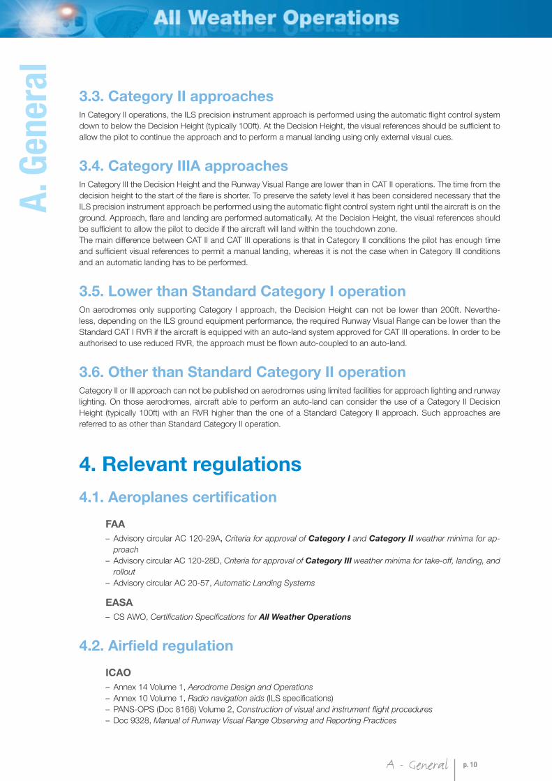
3.3. Category II approachesIn Category II operations, the ILS precision instrument approach is performed using the automatic flight control system
down to below the Decision Height (typically 100ft). At the Decision Height, the visual references should be sufficient to
allow the pilot to continue the approach and to perform a manual landing using only external visual cues.
3.4. Category IIIA approachesIn Category III the Decision Height and the Runway Visual Range are lower than in CAT II operations. The time from the
decision height to the start of the flare is shorter. To preserve the safety level it has been considered necessary that the
ILS precision instrument approach be performed using the automatic flight control system right until the aircraft is on the
ground. Approach, flare and landing are performed automatically. At the Decision Height, the visual references should
be sufficient to allow the pilot to decide if the aircraft will land within the touchdown zone.
The main difference between CAT II and CAT III operations is that in Category II conditions the pilot has enough time
and sufficient visual references to permit a manual landing, whereas it is not the case when in Category III conditions
and an automatic landing has to be performed.
3.5. Lower than Standard Category I operationOn aerodromes only supporting Category I approach, the Decision Height can not be lower than 200ft. Neverthe-
less, depending on the ILS ground equipment performance, the required Runway Visual Range can be lower than the
Standard CAT I RVR if the aircraft is equipped with an auto-land system approved for CAT III operations. In order to be
authorised to use reduced RVR, the approach must be flown auto-coupled to an auto-land.
3.6. Other than Standard Category II operationCategory II or III approach can not be published on aerodromes using limited facilities for approach lighting and runway
lighting. On those aerodromes, aircraft able to perform an auto-land can consider the use of a Category II Decision
Height (typically 100ft) with an RVR higher than the one of a Standard Category II approach. Such approaches are
referred to as other than Standard Category II operation.
4. Relevant regulations
4.1. Aeroplanes certification
FAA
– Advisory circular AC 120-29A, Criteria for approval of Category I and Category II weather minima for ap-
proach
– Advisory circular AC 120-28D, Criteria for approval of Category III weather minima for take-off, landing, and
rollout
– Advisory circular AC 20-57, Automatic Landing Systems
EASA
– CS AWO, Certification Specifications for All Weather Operations
4.2. Airfield regulation
ICAO
– Annex 14 Volume 1, Aerodrome Design and Operations
– Annex 10 Volume 1, Radio navigation aids (ILS specifications)
– PANS-OPS (Doc 8168) Volume 2, Construction of visual and instrument flight procedures
– Doc 9328, Manual of Runway Visual Range Observing and Reporting Practices

A - General p. 11
Other
Each State may have its own policy to approve its aerodromes for Low Visibility Operations. Those regulations
are not supposed to be less restrictive than ICAO Annexes otherwise differences should be notified.
4.3. Operational regulation
ICAO
– Annex 6, Operation of Aircraft
– Doc 9365, Manual of All Weather Operations
FAA
– Advisory circular AC 120-29A, Criteria for approval of Category I and Category II weather minima for ap-
proach
– Advisory circular AC 120-28D, Criteria for approval of Category III weather minima for take-off, landing, and
rollout
EASA
– EU-OPS Subpart E, All Weather Operations
Other
Each State may have its own operational regulation
It is worth noting that harmonisation was conducted between EASA and FAA operational regulations for CAT II and CAT
III operations which are now very similar.
5. Definitions
5.1. General
All Weather OperationsICAO Doc 9365 – Foreword
Any taxi, take-off and landing operations in conditions where visual reference is limited by weather conditions.
Aerodrome operating minima for take-off
ICAO Annex 6 – Chapter 1: Definition
The limits of usability of an aerodrome expressed in terms of runway visual range and/or visibility and, if necessary,
cloud conditions.
Aerodrome operating minima for precision approach and landing operations
ICAO Annex 6 – Chapter 1: Definition
The limits of usability of an aerodrome expressed in terms of visibility and/or runway visual range and decision
altitude/height (DA/H) as appropriate to the category of the operation.
Decision altitude (DA) or decision height (DH)
ICAO Annex 6 – Chapter 1: Definition
A specified altitude or height in the precision approach or approach with vertical guidance at which a missed
approach must be initiated if the required visual reference to continue the approach has not been established.
Note: Decision altitude (DA) is referenced to mean sea level and decision height (DH) is referenced to the
threshold elevation.

A - General p. 12
A. G
en
era
l
According to EASA, the Decision Height for Category II, Category III and other than Standard Category II operations is
determined by means of radio-altimeter.
For some specific Category II approaches, the FAA gives free choice on DH recognition (radio-altimeter, inner markers
or barometric altimeter).
Low Visibility Operations (LVO)
For this specific document, LVO includes Low Visibility Take-Off, Category II approaches, Category IIl approaches, other
than Standard CAT II and lower than Standard CAT I approaches.
Low Visibility Procedures (LVP) - EASA definitionEU-OPS 1.435 Terminology
Procedures applied at an aerodrome for the purpose of ensuring safe operations during Lower than Standard
Category I, Other than Standard Category II, Category II and III approaches and Low Visibility Take-Offs.
Low Visibility Take-Off (LVTO) - EASA definitionEU-OPS 1.435 Terminology
A Low Visibility Take-Off is a take off where the Runway Visual Range is less than 400m.
Runway visual range (RVR)ICAO Annex 6 – Chapter 1: Definition
The range over which the pilot of an aircraft on the centre line of a runway can see the runway surface markings
or the lights delineating the runway or identifying its centre line.
NOTE: Category II and Category III instrument approach and landing operations shall not be authorised unless RVR information is provided.
5.2. Categories of precision approach and landing
operations
5.2.1. Category II (CAT II)
ICAO and FAAICAO Annex 6 – Chapter 1: Definition
AC 120-29A - Appendix 1: Definitions and acronyms
A Category II operation is a precision instrument approach and landing with a decision height lower than 60 m
(200 ft), but not lower than 30 m (100 ft), and a runway visual range not less than 350 m.
EASAEU-OPS 1.430 - Appendix 1 (new): Aerodrome operating minima (f)
A Category II operation is a precision instrument approach and landing using ILS or MLS with a decision height
below 200 ft but not lower than 100 ft; and a runway visual range of not less than 300 m.
NOTE: For the minimum RVR requested, the EASA definition is slightly different from the ICAO and FAA definitions: not less than 350 m for
ICAO and FAA but not less 300 m for EASA.

A - General p. 13
5.2.2. Category IIIA (CAT IIIA)
ICAO and FAAICAO Annex 6 – Chapter 1: Definition
AC 120-29A - Appendix 1: Definitions and acronyms
A Category IIIA operation is a precision instrument approach and landing with a decision height lower than 30 m
(100 ft) or no decision height; and a runway visual range not less than 200 m.
EASAEU-OPS 1.430 - Appendix 1 (new): Aerodrome operating minima (g)
A Category IIIA operation is a precision instrument approach and landing using ILS or MLS with a decision height
lower than 100 ft; and a runway visual range not less than 200 m.
NOTE: The ICAO and FAA regulations differ from EASA by considering CAT IIIA approaches with no DH. EASA systematically associates CAT
IIIA approaches with a decision height.
5.2.3. Category IIIB (CAT IIIB)
ICAO and FAAICAO Annex 6 – Chapter 1: Definition
AC 120-29A - Appendix 1: Definitions and acronyms
A Category IIIB operation is a precision instrument approach and landing with a decision height lower than 15 m
(50 ft) or no decision height; and a runway visual range less than 200m but not less than 50 m.
EASAEU-OPS 1.430 - Appendix 1 (new): Aerodrome operating minima (g)
A Category IIIB operation is a precision instrument approach and landing using ILS or MLS with a decision height
lower than 100 ft, or no decision height; and a runway visual range lower than 200 m but not less than 75 m.
NOTE: The ICAO and FAA regulations differ from EASA on the minimum RVR associated with CAT III B approaches.
5.2.4. Category IIIC (CAT IIIC)
ICAO and FAAICAO Annex 6 – Chapter 1: Definition
AC 120-29A - Appendix 1: Definitions and acronyms
A Category IIIC operation is a precision instrument approach and landing with no decision height and no runway
visual range limitations.
EASA
CAT III C operations are not currently authorised so EASA does not make reference to this sub-category.
5.2.5. Lower than Standard Category I
EASAEU-OPS 1.435 Terminology
A Category I Instrument Approach and Landing Operation using Category I DH, with an RVR lower than would
normally be associated with the applicable DH.

A - General p. 14
A. G
en
era
l
5.2.6. Other than Standard Category II
EASAEU-OPS 1.435 Terminology
A Category II Instrument Approach and Landing Operation to a runway where some or all of the elements of the
ICAO Annex 14 Precision Approach Category II lighting system are not available.
5.3. SummaryDefinitions of Categories of precision approach give the lowest acceptable minima. During operations those values
may be limited by aircraft capability, by airfield limitation, by crew individual qualification or by operator’s authorisation.
ICAO FAA EASA
Lower than stand.
CAT I
DH – – DH ≥200ft
RVR – – 400m≤RVR
CAT II
DH 100ft ≤ DH < 200ft 100ft ≤ DH < 200ft 100ft ≤ DH < 200ft
RVR 350m ≤ RVR
1200ft ≤ RVR
350m ≤ RVR < 800m
1200ft ≤ RVR < 2400ft
300m ≤ RVR
1000ft ≤ RVR
Other than stand.
CAT II
DH – – 100ft ≤ DH < 200ft
RVR – – 350m ≤ RVR
CAT IIIA
DH No DH or DH < 100ft No DH or DH < 100ft DH < 100ft
RVR 200m ≤ RVR
700ft ≤ RVR
200m ≤ RVR
700ft ≤ RVR
200m ≤ RVR
700ft ≤ RVR
CAT IIIB
DH DH < 50ft or No DH DH < 50ft or No DH DH < 100ft or No DH
RVR 50m ≤ RVR < 200m
150ft ≤ RVR < 700ft
50m ≤ RVR < 200m
150ft ≤ RVR < 700ft
75m ≤ RVR < 200m
250ft ≤ RVR < 700ft
CAT IIICDH No DH No DH –
RVR No RVR limitation No RVR limitation –
Table A1: Summary of approach category definitions, in accordance with ICAO, FAA, and EASA Regulations
ICAO Annex 6 – Chapter 1: Definition
Note: Where decision height (DH) and runway visual range (RVR) fall into different categories of operation, the
instrument approach and landing operation would be conducted in accordance with the requirements of the
most demanding category (e.g. an operation with a DH in the range of CAT IIIA but with an RVR in the range of
CAT IIIB would be considered a CAT IIIB operation or an operation with a DH in the range of CAT II but with an
RVR in the range of CAT I would be considered a CAT II operation).
Acceptable operational correspondance meter/feet (according to ICAO)
15m = 50ft 30m = 100ft 50m = 150ft 75m = 250ft
100m = 300ft 150m = 500ft 175m = 600ft 200m = 700ft
300m = 1000ft 350m = 1200ft 500m = 1600ft 550m = 1800ft
600m = 2000ft 800m = 2400ft 1000m = 3000ft 1200m = 4000ft
1600m = 5000ft

B - Revision of low visibility weather conditions p. 15
B. Revision of low visibility weather
conditions

B - Revision of low visibility weather conditions p. 16
B. R
evi
sion
of
low
vis
ibil
ity
wea
ther
con
dit
ion
s
1. The characteristics of fogAlthough visibility may be reduced by the presence in the air of solid particles such as smoke, dust or sand, most of
the time low visibility conditions are caused by fog.
There is fog if the visibility is less than 1000m and the obscuring agent is water droplets. Fog differs from rain or mist in
that its water particles are more minute and suspended and do not fall earthward.
The droplets of water suspended in the air near the earth’s surface act on scattering the light and thus reduce the vis-
ibility near the ground.
The formation of a fog layer occurs when a moist air mass is cooled to its saturation point (dew point): the water vapor
within the air mass condenses on small particles in the air to form liquid cloud droplets. This cooling can be the result of:
– radiative processes (radiation fog),
– advection of warm air over cold surfaces (advection fog),
– evaporation of precipitation (precipitation or frontal fog),
– movement of humid air up or down the hillside (upslope fog or valley fog).
1.1. Radiation fogRadiation fog is caused by the radiation cooling of earth’s surface.
After sunset, earth receives no heat from the sun, but its surface continues to reradiate heat. The surface begins to
cool because of this heat loss. As the Earth cools, the layer of air adjacent to the surface is cooled by conduction.
This causes the layer near earth to be cooler than the air immediately above it, a condition called an inversion. If the air
beneath the inversion layer is sufficiently moist and cools to its dew point, fog forms.
In case of a calm wind and since air is a poor conductor of heat, this cooling by conduction affects only a very shal-
low layer i.e. a few inches deep. Wind of low speed (3 to 5 knots) causes slight, turbulent currents. Such turbulence is
enough to spread the fog through deeper layers.
As nocturnal cooling continues, the air temperature drops further, more moisture is condensed, and fog becomes
deeper and denser. If wind speed is between 5 and 10 knots then the fog will usually thicken vertically. Winds greater
than 10 knots usually result in the formation of low scud, stratus, or stratocumulus.
At sunrise, the Earth is heated. Radiation from the warming surface heats the lower air, causing an evaporation of the
lower part of fog, thereby giving the appearance of lifting fog. Before noon, the radiated heat from the warming of the
earth surface destroys the inversion process, so then the fog evaporates into warmed air.
Radiation fog appears over land, it never forms over a water surface and it may cover a wide area. The conditions giving
rise to the formation of radiating fog are:
– cloudless nights, allowing the earth to lose heat by radiation,
– moist air that requires a little cooling to reach the dew point temperature,
– light winds (5-7kts) to mix the lower layers of air, thereby thickening the fog layer.
Such conditions are common in high-pressure areas during autumn and winter in temperate zones.
Further radiational
cooling at top of
fog layer, deepens it.
Fog forms first atthe surface, thickeningas cooling continues.
Heat radiating from thesurface at night, coolsthe bottom air until itreaches saturation.
Figure B1: Radiation fog

B - Revision of low visibility weather conditions p. 17
1.2. Advection fogAdvection fogs are formed when air moves either over a cooler surface or over a warmer moist surface and, as a
result, the air mass reaches saturation.
Most often this occurs when a moist air mass moves over a cold surface with a temperature lower than the dew point
of the moving air. Cooling from below takes place and gradually builds up a fog layer. The cooling rate depends on
the wind speed and the difference between the air temperature and the temperature of the surface over which the air
travels. A low wind speed heightens the likelihood as the air remains in contact with the surface long enough to suf-
ficiently cool the air layer.
Advection fogs are often persistent since the weather situation that forms them can last a day or more. Usually, either a
frontal passage with a change of air-mass or a major change in wind direction are needed for the dissipation of advec-
tion fog.
Fog forms
Colder surface
Warmer, moist airmoves over a coldersurface and its temperature drops
Figure B2: Advection fog
1.3. Frontal / Precipitation fogThis fog type is due to the evaporation of falling rain and occurs under the frontal surface in the cold air mass. Pre-
cipitation falls from the lifted warm air through the cold air. Evaporation from the rain continues as long as the raindrop
temperature is higher than the temperature of the air, even though the cold air is already saturated. Naturally, the
upper regions become saturated first because, at higher altitude, both the temperature and dew point are lower. As
rain evaporation continues, a layer of clouds begins to build down from the frontal surface. Eventually, this cloud layer
extends to the ground turning into fog.
Cold fronts usually move so rapidly and have such narrow bands of precipitation and high wind speeds that a cold front
fog is comparatively rare and short lived. A warm front fog, on the other hand, is fairly common. Warm-front fog may
cover a wide area. Also this type of fog is deep because it extends from the ground to the frontal surface.
fog
rain cloud
cold airwarm air
front
precipitation falls through warm air
evaporation leads to saturation
Figure B3: Frontal fog

B - Revision of low visibility weather conditions p. 18
B. R
evi
sion
of
low
vis
ibil
ity
wea
ther
con
dit
ion
s
1.4. Upslope and valley fogsUpslope fog is caused by adiabatic cooling of rising air. When moist, warm air is forced to move over a terrain obsta-
cle, it cools to some degree as it rises, the degree of cooling depending on the amount of rise. During that cooling, if the
air temperature falls below dew point, the resulting condensation will form a cloud. The air must be stable before it starts
its motion, so that lifting does not cause convection, nor vertical currents, which would dissipate the fog. Wind speed
is needed, of course, to cause upslope motion. This type of fog is deep and requires considerable time to dissipate.
Fog forms
on slope.
Moist air flows
toward slope.
As air rises with theterrain, it cools tocondensation temperature.
Figure B4: Upslope fog
Valley fog forms during the evening as a result of air being cooled by radiation on slopy topographical features. As this
air becomes denser than its surroundings, it starts going down the slope. This results in the creation of a pool of cold
air at valley floor level. If the air is cold enough to reach its dew point, fog formation occurs.
Fog forms in valley
Air cools at
higher elevations.
Cold air drains
downslope
into valley.
Cold air drainagereduces air temperature invalley to condensation point.
Figure B5: Valley fog
2. Effects of precipitation, wind and turbulences
2.1. The effect of precipitationPrecipitation includes drizzle, rain, snow, ice crystals and hail. Although liquid precipitation on windshields can be
a serious irritation for pilots, it does not seriously limit visibility, except when rain or drizzle is associated with fog. Even
heavy rain does not usually limit visibility to less than 1 km.

B - Revision of low visibility weather conditions p. 19
Figure B6: View from windshield during precipitation
Snow fall is a different matter; a very light snowfall alone can reduce visibility considerably. As snowfall becomes heavy,
visibility may drop to only a few meters.
Blowing snow is to be expected when loose snow is raised by the wind. The limited visibility may extend to a consider-
able height. This problem is quite significant in cold climates.
Snow also affects approach and runway lighting intensity, thus reducing the chances of acquiring visual cues at Deci-
sion Height. Furthermore, the actual visibility may be less than the horizontally measured visibility because of the lack
of contrast between the approach lighting and the snow-covered ground.
Figure B7: Snowy environment
2.2. The effect of wind and turbulencesLow visibility conditions are usually due to the presence of fog which often appears in anticyclones. Therefore most
of the time CAT II and CAT III approaches are performed with light or moderate wind, except on a limited number of
airports where specific conditions may associate fog and strong wind.
For CAT II operations, the ATR flight manual states the maximum “demonstrated wind”. It corresponds to the worth
wind conditions encountered during certification flight tests. Therefore it should not be considered as a limitation. It is
the operator’s responsibility to set the limit as per his national operational regulations.
CAT III operations are constrained in respect of the wind component. Unlike the demonstrated wind for manual land-
ings, the autoland wind capabilities are always limiting. The maximum crosswind values for auto-land operations are
often less than the manually demonstrated crosswind landings.