Embed Size (px)
Citation preview
UNCONTROLLED IF
REPRODUCED
OPERATING LIMITATIONS
Table of Contents
SAAB Flight CrewOperating Manual
RO.340.0301
Approved by the General Manager Flight Operations
Chapter 2 Page i
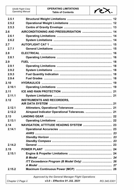
2 OPERATING LIMITATIONS ......................................................... 1
2.1 GENERAL ................................................................................................. 1
2.1.1 Introduction ....................................................................................... 1
2.1.2 Main Dimensions ............................................................................... 1
2.2 AIRCRAFT GENERAL ............................................................................. 2
2.2.1 Icing Conditions (M) .......................................................................... 2
2.2.2 Airspeeds ........................................................................................... 2
Maximum Flaps Extended Speeds, VFE ......................................... 2
Maximum Landing Gear Speeds ...................................................... 3
Minimum Control Speeds ................................................................. 3
Maximum Operating Speed, VMO .................................................... 3
Maximum Manoeuvring Speed, VA .................................................. 4
Maximum Rough Air Penetration Speed, VRA ............................... 4
2.2.3 Flight Envelope .................................................................................. 5
2.2.4 Manoeuvring Load Factors .............................................................. 6
2.2.5 Kinds Of Operation ........................................................................... 6
2.2.6 Minimum Flight Crew ........................................................................ 6
2.2.7 Maximum Number Of Occupants ..................................................... 6
2.2.8 Operational Limits ............................................................................. 7
2.2.9 Environmental Envelope .................................................................. 7
2.3 MISCELLANEOUS ................................................................................... 8
2.3.1 Airborne Collision Avoidance System (ACAS) ............................... 8
2.3.2 Flight Director .................................................................................... 8
2.3.3 Autopilot ............................................................................................. 8
2.3.4 Yaw Damper ....................................................................................... 8
2.3.5 Flap ..................................................................................................... 8
2.3.6 Configuration Deviation List (CDL) ................................................. 9
2.3.7 Placards and Instrument Markings .................................................. 9
2.3.8 Cargo Fire .......................................................................................... 9
2.3.9 Attitude/Heading Reference System ............................................... 9
2.3.10 Terrain Awareness and Warning System (TAWS) .......................... 9
2.3.11 Flight Deck Access and Egress ....................................................... 9
2.4 WEIGHTS (SF340B & 340B (WT)) ......................................................... 10
2.4.1 Structural Weight Limitations ........................................................ 10
2.4.2 Operational Weight Limitations ..................................................... 10
2.4.3 Centre of Gravity ............................................................................. 11
2.5 WEIGHTS (SF340A) ............................................................................... 12
v3.0 – Effective 01 JUL 2021
UNCONTROLLED IF
REPRODUCED
SAAB Flight CrewOperating Manual
OPERATING LIMITATIONS
Table of Contents
Chapter 2 Page ii
Approved by the General Manager Flight Operations
RO.340.0301 v3.0 – Effective 01 JUL 2021
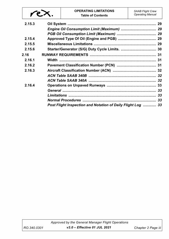
2.5.1 Structural Weight Limitations ........................................................ 12
2.5.2 Operational Weight Limitations ..................................................... 12
2.5.3 Centre of Gravity Envelope ............................................................ 13
2.6 AIRCONDITIONING AND PRESSURISATION ..................................... 14
2.6.1 Operating Limitations ..................................................................... 14
2.6.2 System Limitations ......................................................................... 14
2.7 AUTOFLIGHT CAT 1 ............................................................................. 15
2.7.1 General Limitations ......................................................................... 15
2.8 ELECTRICAL ......................................................................................... 16
2.8.1 Operating Limitations ..................................................................... 16
2.9 FUEL ...................................................................................................... 18
2.9.1 Operating Limitations ..................................................................... 18
2.9.2 System Limitations ......................................................................... 18
2.9.3 Fuel Quantity Indication ................................................................. 18
2.9.4 Fuel Grades ..................................................................................... 18
2.10 HYDRAULICS ........................................................................................ 19
2.10.1 Operating Limitations ..................................................................... 19
2.11 ICE AND RAIN PROTECTION ............................................................... 21
2.11.1 System Limitations ......................................................................... 21
2.12 INSTRUMENTS AND RECORDERS,
AIR DATA SYSTEM ............................................................................... 21
2.12.1 Altimeters, Operational Tolerances ............................................... 21
2.12.2 Airspeed Indicator Operational Tolerances. ................................. 21
2.13 LANDING GEAR .................................................................................... 22
2.13.1 Operating Limitations ..................................................................... 22
2.14 NAVIGATION, ATTITUDE HEADING SYSTEM .................................... 23
2.14.1 Operational Accuracies .................................................................. 23
AHRS ................................................................................................ 23
Standby Horizon .............................................................................. 23
Standby Compass ........................................................................... 23
2.14.2 General ............................................................................................. 23
2.15 POWER PLANT .................................................................................... 24
2.15.1 Engine & Propeller Limitations ...................................................... 24
B Model ............................................................................................ 24
ITT Exceedance Program (B Model Only) ..................................... 26
A Model ............................................................................................ 27
2.15.2 Maximum Continuous Power (MCP) ............................................. 28
UNCONTROLLED IF
REPRODUCED
OPERATING LIMITATIONS
Table of Contents
SAAB Flight CrewOperating Manual
RO.340.0301
Approved by the General Manager Flight Operations
Chapter 2 Page iii
2.15.3 Oil System ........................................................................................ 29
Engine Oil Consumption Limit (Maximum) ................................... 29
PGB Oil Consumption Limit (Maximum) ....................................... 29
2.15.4 Approved Type Of Oil (Engine and PGB) ...................................... 29
2.15.5 Miscellaneous Limitations .............................................................. 29
2.15.6 Starter/Generator (S/G) Duty Cycle Limits. ................................... 30
2.16 RUNWAY REQUIREMENTS .................................................................. 31
2.16.1 Width ................................................................................................ 31
2.16.2 Pavement Classification Number (PCN) ....................................... 31
2.16.3 Aircraft Classification Number (ACN) ........................................... 32
ACN Table SAAB 340B ................................................................... 32
ACN Table SAAB 340A ................................................................... 32
2.16.4 Operations on Unpaved Runways ................................................. 33
General ............................................................................................. 33
Limitations ....................................................................................... 33
Normal Procedures ......................................................................... 33
Post Flight Inspection and Notation of Daily Flight Log ............. 33
v3.0 – Effective 01 JUL 2021

UNCONTROLLED IF
REPRODUCED
This page intentionally left blank.
UNCONTROLLED IF
REPRODUCED
OPERATING LIMITATIONS
General
SAAB Flight CrewOperating Manual
RO.340.0301
Approved by the General Manager Flight Operations
Chapter 2 Page 1
2 OPERATING LIMITATIONS
2.1 GENERAL
2.1.1 Introduction
The SAAB 340 operating limitations contained in this chapter are reproduced from the Aircraft
Flight Manual. Only the limitations that are applicable to the Regional Express fleet have been
included. Unless specified limitations refer to both the A and B models. In order to operate the
aircraft safely, observance of these limitations is mandatory.
In the event of a disagreement between the Flight Crew Operating Manual and the Aircraft Flight
Manual, the Aircraft Flight Manual takes precedence.
If a limitation is exceeded both crew member must not operate further sectors until approval has
been given from Flight Operations management.
NOTE
Items in this chapter marked with an (M) are required to be
committed to memory with other limitations for reference when
required.
2.1.2 Main Dimensions
Length ..................................................................................................................... 19.73 m
Height ........................................................................................................................ 7.00 m
Span (without extended wingtips) ........................................................................... 21.44 m (M)
Span (with extended wingtips) ................................................................................. 22.75 m (M)
Propeller clearance ................................................................................................... 0.51 m
Passenger door .............................................................................................. 0.69 x 1.60 m
Cargo door ..................................................................................................... 1.35 x 1.30 m
Baggage compartment ........................................................................................... 6.8 cu m
v3.0 – Effective 01 JUL 2021
UNCONTROLLED IF
REPRODUCED
SAAB Flight CrewOperating Manual
OPERATING LIMITATIONS
Aircraft General
Chapter 2 Page 2
Approved by the General Manager Flight Operations
RO.340.0301
2.2 AIRCRAFT GENERAL
2.2.1 Icing Conditions (M)
Icing conditions exist when visible moisture in any form is present (such as clouds, fog with visibility
of one mile (1,850 m) or less, rain, snow, sleet, ice crystals) or standing water, slush, or snow (hard
packed snow excluded) is present on the ramps, taxiways or runways and the OAT or SAT is +5°C
and below during ground and flight operation. In these conditions, or whenever the blue ICE SPD
status light or EAI is on, the minimum speed for flight in icing conditions must be observed. IAS
mode must be selected on the FD if climbing when these conditions exist.
CAUTION
The defined or minimum speed for flight in icing conditions
must be observed whenever the blue ICE SPD status light or
EAI is ON regardless of the actual conditions the aircraft is
operating in.
2.2.2 Airspeeds
The limits are in terms of indicated values. Instrument error is assumed to be zero.
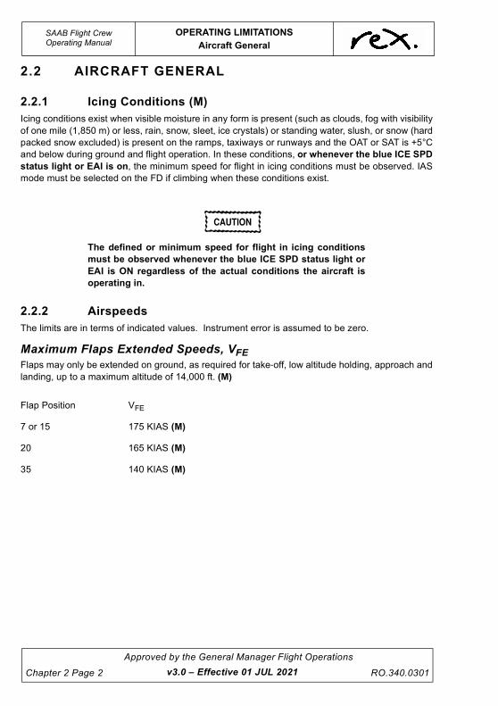
Maximum Flaps Extended Speeds, VFEFlaps may only be extended on ground, as required for take-off, low altitude holding, approach and
landing, up to a maximum altitude of 14,000 ft. (M)
Flap Position VFE
7 or 15 175 KIAS (M)
20 165 KIAS (M)
35 140 KIAS (M)
v3.0 – Effective 01 JUL 2021
UNCONTROLLED IF
REPRODUCED
OPERATING LIMITATIONS
Aircraft General
SAAB Flight CrewOperating Manual
RO.340.0301
Approved by the General Manager Flight Operations
Chapter 2 Page 3
Maximum Landing Gear Speeds
Minimum Control Speeds
Maximum Operating Speed, VMO
CAUTION
The maximum operating speed VMO may not be deliberately
exceeded in any regime of flight (climb, cruise or descent)
unless a higher speed is authorised for flight test or pilot
training.
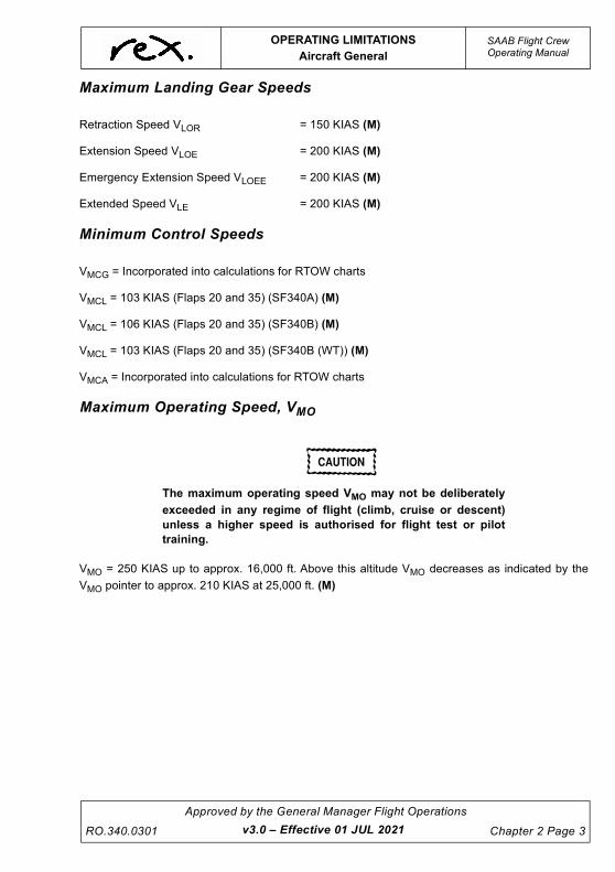
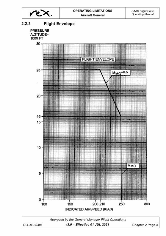
VMO = 250 KIAS up to approx. 16,000 ft. Above this altitude VMO decreases as indicated by the
VMO pointer to approx. 210 KIAS at 25,000 ft. (M)
Retraction Speed VLOR = 150 KIAS (M)
Extension Speed VLOE = 200 KIAS (M)
Emergency Extension Speed VLOEE = 200 KIAS (M)
Extended Speed VLE = 200 KIAS (M)
VMCG = Incorporated into calculations for RTOW charts
VMCL = 103 KIAS (Flaps 20 and 35) (SF340A) (M)
VMCL = 106 KIAS (Flaps 20 and 35) (SF340B) (M)
VMCL = 103 KIAS (Flaps 20 and 35) (SF340B (WT)) (M)
VMCA = Incorporated into calculations for RTOW charts
v3.0 – Effective 01 JUL 2021
UNCONTROLLED IF
REPRODUCED
SAAB Flight CrewOperating Manual
OPERATING LIMITATIONS
Aircraft General
Chapter 2 Page 4
Approved by the General Manager Flight Operations
RO.340.0301
Maximum Manoeuvring Speed, VA
CAUTION
Full application of rudder and aileron controls, as well as
manoeuvres that involve angles of attack near stall, must be
confined to speeds below VA.
VA = 180 KIAS (M)
Maximum Rough Air Penetration Speed, VRAVRA = 190 KIAS up to 21,000 ft ISA. Above this altitude, reduce the speed as indicated by the VMO
pointer minus 30 kts. (M)
v3.0 – Effective 01 JUL 2021
UNCONTROLLED IF
REPRODUCED
OPERATING LIMITATIONS
Aircraft General
SAAB Flight CrewOperating Manual
RO.340.0301
Approved by the General Manager Flight Operations
Chapter 2 Page 5
2.2.3 Flight Envelope
v3.0 – Effective 01 JUL 2021
UNCONTROLLED IF
REPRODUCED
SAAB Flight CrewOperating Manual
OPERATING LIMITATIONS
Aircraft General
Chapter 2 Page 6
Approved by the General Manager Flight Operations
RO.340.0301
2.2.4 Manoeuvring Load Factors
2.2.5 Kinds Of Operation
The aircraft is eligible for the following kinds of operation when the appropriate instruments and
equipment required by airworthiness and/or operating regulations are installed, approved, and are
in operable condition:
• Atmospheric icing conditions,
• Day and night VFR, and
• IFR.
WARNING
No acrobatic manoeuvres, including spins are approved.
2.2.6 Minimum Flight Crew
Required flight crew: 2 (Pilot and Co-pilot).
2.2.7 Maximum Number Of Occupants
The Maximum number of occupants to be carried shall be in accordance with ‘8.8.5 Carriage of
Passengers in Excess of the Maximum Number of Seat Installed’ of the Policy and Procedures
Manual.
Flaps retracted: + 2.75 to – 1.0
Flaps extended: + 2.0 to + 0
v3.0 – Effective 01 JUL 2021
UNCONTROLLED IF
REPRODUCED
OPERATING LIMITATIONS
Aircraft General
SAAB Flight CrewOperating Manual
RO.340.0301
Approved by the General Manager Flight Operations
Chapter 2 Page 7
2.2.8 Operational Limits
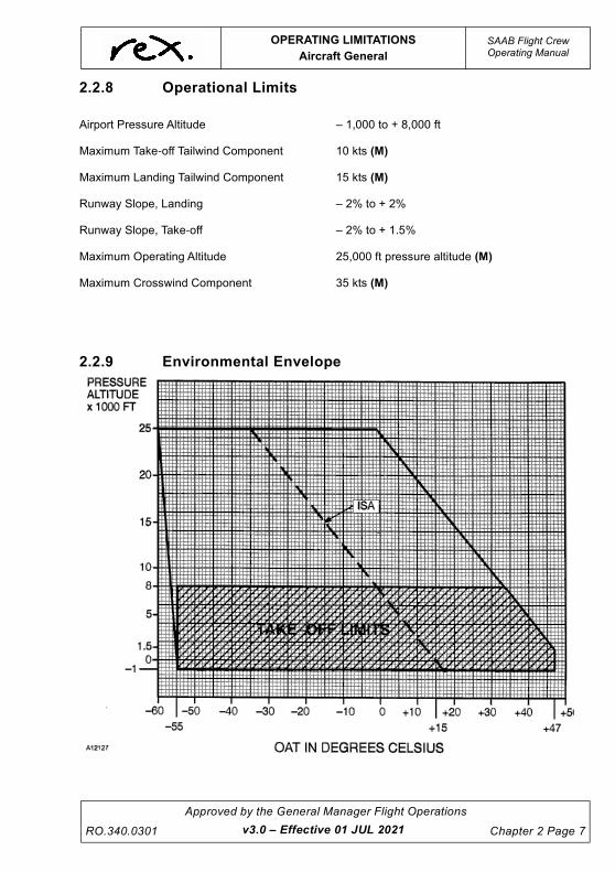
2.2.9 Environmental Envelope
Airport Pressure Altitude – 1,000 to + 8,000 ft
Maximum Take-off Tailwind Component 10 kts (M)
Maximum Landing Tailwind Component 15 kts (M)
Runway Slope, Landing – 2% to + 2%
Runway Slope, Take-off – 2% to + 1.5%
Maximum Operating Altitude 25,000 ft pressure altitude (M)
Maximum Crosswind Component 35 kts (M)
v3.0 – Effective 01 JUL 2021
UNCONTROLLED IF
REPRODUCED
SAAB Flight CrewOperating Manual
OPERATING LIMITATIONS
Miscellaneous
Chapter 2 Page 8
Approved by the General Manager Flight Operations
RO.340.0301
2.3 MISCELLANEOUS
2.3.1 Airborne Collision Avoidance System (ACAS)
Deviations from the ATC assigned altitude is authorised only to the extent necessary to comply
with an ACAS Resolution Advisory (RA). (M)
Manoeuvres must not be based solely on information presented on the Traffic Advisory (TA)
display. (M)
2.3.2 Flight Director
Use of flight director information in go-around mode during take-off is not authorised. (M)
2.3.3 Autopilot
Autopilot operations not authorised:
• Below 200 ft AGL - during take-off or go-around. (M)
• Below 500 ft AGL - during cruise. (M)
• Below 50 ft AGL - during approach. (M)
• Below 100 ft AGL - for a non-coupled approach. (M)
In icing conditions (as defined) FD/AP IAS MODE IS THE ONLY VERTICAL MODE TO BE USED
DURING CLIMB WHEN ICE ACCUMULATION IS OBSERVED OR IF IT IS NOT CERTAIN THERE
IS NO ICE ACCUMULATION ON THE AIRCRAFT. (M)
It is a requirement to disconnect the autopilot following an engine failure and re-trim the aircraft
before re-engagement of the autopilot. (M)
This is to avoid the autopilot holding roll trim forces in case of an unexpected disconnect (e.g. stall
warning)
Maximum Roll trim tolerance for dispatch + ½ Unit from neutral.
2.3.4 Yaw Damper
Yaw Damper Operation is not authorised for:
• Take-off (M),
• Go-around (M), or
• Landing (M).
2.3.5 Flap
• Landing Flap is to be set by 300 ft radio height during normal landing. (M)
Company requires that the final flap setting is called for at no less than 500 ft AGL.
• When holding in icing conditions (as defined) Flap 0 must be used. (M)
v3.0 – Effective 01 JUL 2021
UNCONTROLLED IF
REPRODUCED
OPERATING LIMITATIONS
Miscellaneous
SAAB Flight CrewOperating Manual
RO.340.0301
Approved by the General Manager Flight Operations
Chapter 2 Page 9
2.3.6 Configuration Deviation List (CDL)
When operation is scheduled with certain secondary airframe and engine parts missing, the aircraft
must be operated in accordance with the limitations specified in the CDL, located at the back of the
MEL.
2.3.7 Placards and Instrument Markings
Instrument Colour Codes:
Operating limits .............................................................................................................RED (M)
Caution, temporary or idle range ........................................................................... YELLOW (M)
Normal operating range .......................................................................................... GREEN (M)
2.3.8 Cargo Fire
The cargo compartment is classified as a Class C cargo compartment and has been demonstrated
to provide the following minimum fire protection duration, based on cargo compartment
configuration and fire protection system installation.
• 60 min for 340B (WT) (Mod No. 1149 incorporated (2 bottles)). (M)
• 35 min for all other REX aircraft. (M)
2.3.9 Attitude/Heading Reference System
During initialisation on ground the aircraft must not be moved. (M)
Take-off is not permitted until two minutes after initialisation is completed and the attitude difference
between the attitude displayed on both EADIs and the standby attitude indicator is 3 degrees or
less (bank and pitch) and the heading on the compass card is not slewing away from the aircraft
heading. (M)
2.3.10 Terrain Awareness and Warning System (TAWS)
Navigation is not to be predicated on the use of the Terrain (or Obstacle) Awareness Display.
NOTE
The Terrain Awareness Display is intended to serve as a
situational awareness tool only. It does not have the integrity,
accuracy or fidelity on which to solely base decisions for terrain or
obstacle avoidance.
2.3.11 Flight Deck Access and Egress
The flight deck door must be kept closed and locked at all times during flight except to permit
access and egress in accordance with applicable aviation authority approved procedures for
opening, closing, and locking the door contained in the PPM.
Another crew member must be present on the flight deck when one of the required flight crew
leaves the flight deck during flight and the Flight Deck Door is locked.
v3.0 – Effective 01 JUL 2021
UNCONTROLLED IF
REPRODUCED
SAAB Flight CrewOperating Manual
OPERATING LIMITATIONS
Weights (SF340B & 340B (WT))
Chapter 2 Page 10
Approved by the General Manager Flight Operations
RO.340.0301
2.4 WEIGHTS (SF340B & 340B (WT))
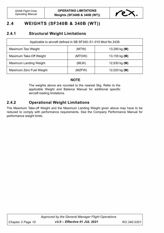
2.4.1 Structural Weight Limitations
NOTE
The weights above are rounded to the nearest 5kg. Refer to the
applicable Weight and Balance Manual for additional specific
aircraft loading limitations.
2.4.2 Operational Weight Limitations
The Maximum Take-off Weight and the Maximum Landing Weight given above may have to be
reduced to comply with performance requirements. See the Company Performance Manual for
performance weight limits.
Applicable to aircraft defined in SB SF340–51–010 Mod No 2438
Maximum Taxi Weight (MTW) 13,290 kg (M)
Maximum Take-Off Weight (MTOW) 13,155 kg (M)
Maximum Landing Weight (MLW) 12,930 kg (M)
Maximum Zero Fuel Weight (MZFW) 12,020 kg (M)
v3.0 – Effective 01 JUL 2021
UNCONTROLLED IF
REPRODUCED
OPERATING LIMITATIONS
Weights (SF340B & 340B (WT))
SAAB Flight CrewOperating Manual
RO.340.0301
Approved by the General Manager Flight Operations
Chapter 2 Page 11
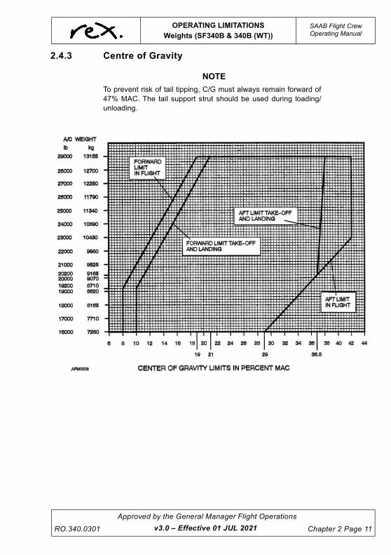
2.4.3 Centre of Gravity
NOTE
To prevent risk of tail tipping, C/G must always remain forward of
47% MAC. The tail support strut should be used during loading/
unloading.
v3.0 – Effective 01 JUL 2021
UNCONTROLLED IF
REPRODUCED
SAAB Flight CrewOperating Manual
OPERATING LIMITATIONS
Weights (SF340A)
Chapter 2 Page 12
Approved by the General Manager Flight Operations
RO.340.0301
2.5 WEIGHTS (SF340A)
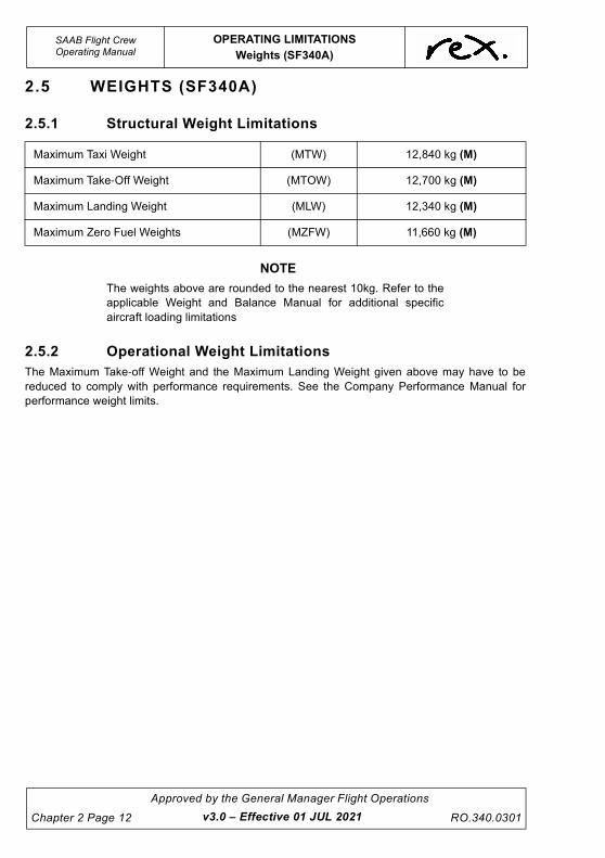
2.5.1 Structural Weight Limitations
NOTE
The weights above are rounded to the nearest 10kg. Refer to the
applicable Weight and Balance Manual for additional specific
aircraft loading limitations
2.5.2 Operational Weight Limitations
The Maximum Take-off Weight and the Maximum Landing Weight given above may have to be
reduced to comply with performance requirements. See the Company Performance Manual for
performance weight limits.
Maximum Taxi Weight (MTW) 12,840 kg (M)
Maximum Take-Off Weight (MTOW) 12,700 kg (M)
Maximum Landing Weight (MLW) 12,340 kg (M)
Maximum Zero Fuel Weights (MZFW) 11,660 kg (M)
v3.0 – Effective 01 JUL 2021
UNCONTROLLED IF
REPRODUCED
OPERATING LIMITATIONS
Weights (SF340A)
SAAB Flight CrewOperating Manual
RO.340.0301
Approved by the General Manager Flight Operations
Chapter 2 Page 13
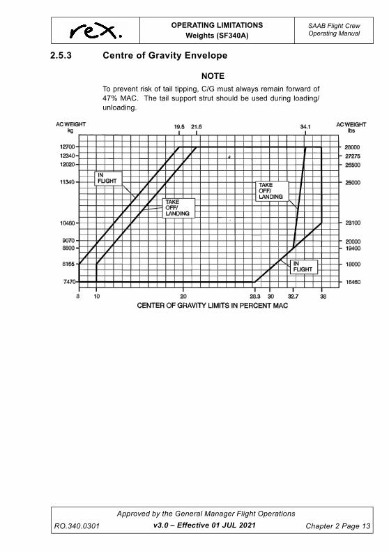
2.5.3 Centre of Gravity Envelope
NOTE
To prevent risk of tail tipping, C/G must always remain forward of
47% MAC. The tail support strut should be used during loading/
unloading.
v3.0 – Effective 01 JUL 2021
UNCONTROLLED IF
REPRODUCED
SAAB Flight CrewOperating Manual
OPERATING LIMITATIONS
Airconditioning and Pressurisation
Chapter 2 Page 14
Approved by the General Manager Flight Operations
RO.340.0301
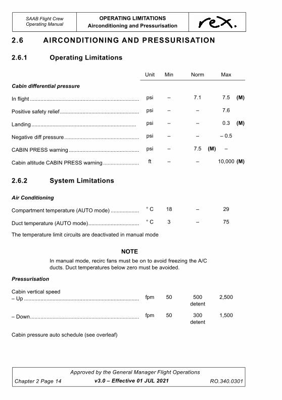
2.6 AIRCONDITIONING AND PRESSURISATION
2.6.1 Operating Limitations
2.6.2 System Limitations
Unit Min Norm Max
Cabin differential pressure
In flight ......................................................................... psi – 7.1 7.5 (M)
Positive safety relief ..................................................... psi – – 7.6
Landing ...................................................................... psi – – 0.3 (M)
Negative diff pressure.................................................. psi – – – 0.5
CABIN PRESS warning ............................................... psi – 7.5 (M) –
Cabin altitude CABIN PRESS warning ........................ ft – – 10,000 (M)
Air Conditioning
Compartment temperature (AUTO mode) ................... ° C 18 – 29
Duct temperature (AUTO mode).................................. ° C 3 – 75
The temperature limit circuits are deactivated in manual mode
NOTE
In manual mode, recirc fans must be on to avoid freezing the A/C
ducts. Duct temperatures below zero must be avoided.
Pressurisation
Cabin vertical speed
– Up ............................................................................. fpm 50 500
detent
2,500
– Down......................................................................... fpm 50 300
detent
1,500
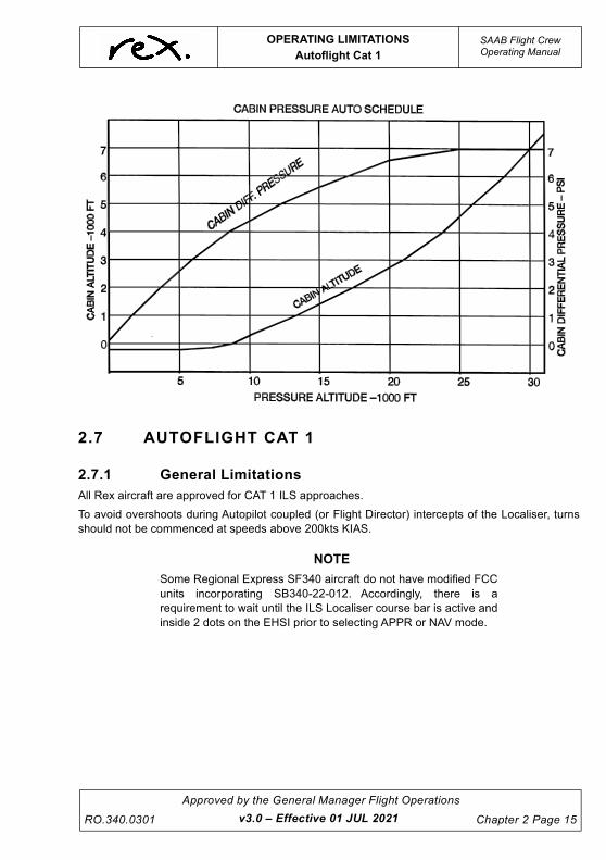
Cabin pressure auto schedule (see overleaf)
v3.0 – Effective 01 JUL 2021
UNCONTROLLED IF
REPRODUCED
OPERATING LIMITATIONS
Autoflight Cat 1
SAAB Flight CrewOperating Manual
RO.340.0301
Approved by the General Manager Flight Operations
Chapter 2 Page 15
2.7 AUTOFLIGHT CAT 1
2.7.1 General Limitations
All Rex aircraft are approved for CAT 1 ILS approaches.
To avoid overshoots during Autopilot coupled (or Flight Director) intercepts of the Localiser, turns
should not be commenced at speeds above 200kts KIAS.
NOTE
Some Regional Express SF340 aircraft do not have modified FCC
units incorporating SB340-22-012. Accordingly, there is a
requirement to wait until the ILS Localiser course bar is active and
inside 2 dots on the EHSI prior to selecting APPR or NAV mode.
v3.0 – Effective 01 JUL 2021
UNCONTROLLED IF
REPRODUCED
SAAB Flight CrewOperating Manual
OPERATING LIMITATIONS
Electrical
Chapter 2 Page 16
Approved by the General Manager Flight Operations
RO.340.0301
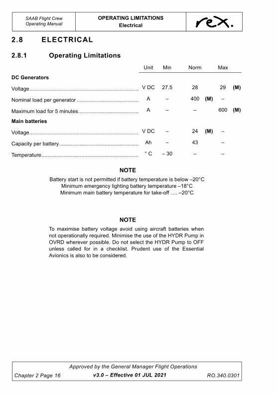
2.8 ELECTRICAL
2.8.1 Operating Limitations
Unit Min Norm Max
DC Generators
Voltage.......................................................................... V DC 27.5 28 29 (M)
Nominal load per generator .......................................... A – 400 (M) –
Maximum load for 5 minutes......................................... A – – 600 (M)
Main batteries
Voltage.......................................................................... V DC – 24 (M) –
Capacity per battery...................................................... Ah – 43 –
Temperature.................................................................. ° C – 30 – –
NOTE
Battery start is not permitted if battery temperature is below –20°C
Minimum emergency lighting battery temperature –18°C
Minimum main battery temperature for take-off …. –20°C
NOTE
To maximise battery voltage avoid using aircraft batteries when
not operationally required. Minimise the use of the HYDR Pump in
OVRD wherever possible. Do not select the HYDR Pump to OFF
unless called for in a checklist. Prudent use of the Essential
Avionics is also to be considered.
v3.0 – Effective 01 JUL 2021
UNCONTROLLED IF
REPRODUCED
OPERATING LIMITATIONS
Electrical
SAAB Flight CrewOperating Manual
RO.340.0301
Approved by the General Manager Flight Operations
Chapter 2 Page 17
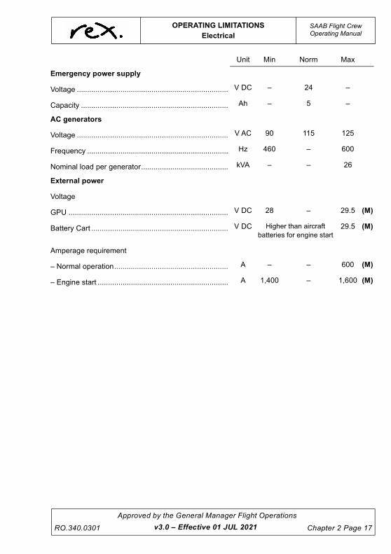
Unit Min Norm Max
Emergency power supply
Voltage ......................................................................... V DC – 24 –
Capacity ....................................................................... Ah – 5 –
AC generators
Voltage ......................................................................... V AC 90 115 125
Frequency .................................................................... Hz 460 – 600
Nominal load per generator.......................................... kVA – – 26
External power
Voltage
GPU ............................................................................. V DC 28 – 29.5 (M)
Battery Cart .................................................................. V DC Higher than aircraft
batteries for engine start29.5 (M)
Amperage requirement
– Normal operation....................................................... A – – 600 (M)
– Engine start ............................................................... A 1,400 – 1,600 (M)
v3.0 – Effective 01 JUL 2021
UNCONTROLLED IF
REPRODUCED
SAAB Flight CrewOperating Manual
OPERATING LIMITATIONS
Fuel
Chapter 2 Page 18
Approved by the General Manager Flight Operations
RO.340.0301
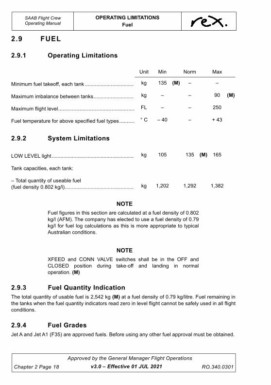
2.9 FUEL
2.9.1 Operating Limitations
2.9.2 System Limitations
NOTE
Fuel figures in this section are calculated at a fuel density of 0.802
kg/l (AFM). The company has elected to use a fuel density of 0.79
kg/l for fuel log calculations as this is more appropriate to typical
Australian conditions.
NOTE
XFEED and CONN VALVE switches shall be in the OFF and
CLOSED position during take-off and landing in normal
operation. (M)
2.9.3 Fuel Quantity Indication
The total quantity of usable fuel is 2,542 kg (M) at a fuel density of 0.79 kg/litre. Fuel remaining in
the tanks when the fuel quantity indicators read zero in level flight cannot be safely used in all flight
conditions.
2.9.4 Fuel Grades
Jet A and Jet A1 (F35) are approved fuels. Before using any other fuel approval must be obtained.
Unit Min Norm Max
Minimum fuel takeoff, each tank .................................. kg 135 (M) – –
Maximum imbalance between tanks............................ kg – – 90 (M)
Maximum flight level.................................................. FL – – 250
Fuel temperature for above specified fuel types.......... ° C – 40 – + 43
LOW LEVEL light ......................................................... kg 105 135 (M) 165
Tank capacities, each tank:
– Total quantity of useable fuel
(fuel density 0.802 kg/l)................................................ kg 1,202 1,292 1,382
v3.0 – Effective 01 JUL 2021
UNCONTROLLED IF
REPRODUCED
OPERATING LIMITATIONS
Hydraulics
SAAB Flight CrewOperating Manual
RO.340.0301
Approved by the General Manager Flight Operations
Chapter 2 Page 19
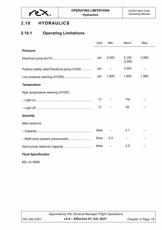
2.10 HYDRAULICS
2.10.1 Operating Limitations
Unit Min Norm Max
Pressure
Electrical pump AUTO.............................................. psi 2,050 2,100
-2,900
2,950
Positive safety relief Electrical pump OVRD............ psi – 3,000 –
Low pressure warning (HYDR) ................................ psi 1,800 1,850 1,900
Temperature
High temperature warning (HYDR)
– Light on ................................................................. ° C – 116 –
– Light off ................................................................. ° C – 93 –
Quantity
Main reservoir
– Capacity ................................................................ litres – 5.1 –
– Refill level (system pressurised) ........................... litres 2.3 – –
Hand pump reservoir capacity ................................. litres – 2.5 –
Fluid Specification
MIL–H–5606
v3.0 – Effective 01 JUL 2021

UNCONTROLLED IF
REPRODUCED
This page intentionally left blank.
UNCONTROLLED IF
REPRODUCED
OPERATING LIMITATIONS
Ice and Rain Protection
SAAB Flight CrewOperating Manual
RO.340.0301
Approved by the General Manager Flight Operations
Chapter 2 Page 21
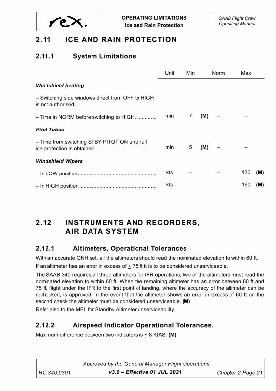
2.11 ICE AND RAIN PROTECTION
2.11.1 System Limitations
2.12 INSTRUMENTS AND RECORDERS,
AIR DATA SYSTEM
2.12.1 Altimeters, Operational Tolerances
With an accurate QNH set, all the altimeters should read the nominated elevation to within 60 ft.
If an altimeter has an error in excess of + 75 ft it is to be considered unserviceable.
The SAAB 340 requires all three altimeters for IFR operations; two of the altimeters must read the
nominated elevation to within 60 ft. When the remaining altimeter has an error between 60 ft and
75 ft, flight under the IFR to the first point of landing, where the accuracy of the altimeter can be
rechecked, is approved. In the event that the altimeter shows an error in excess of 60 ft on the
second check the altimeter must be considered unserviceable. (M)
Refer also to the MEL for Standby Altimeter unserviceability.
2.12.2 Airspeed Indicator Operational Tolerances.
Maximum difference between two indicators is + 8 KIAS. (M)
Unit Min Norm Max
Windshield heating
– Switching side windows direct from OFF to HIGH
is not authorised
– Time in NORM before switching to HIGH............... min 7 (M) – –
Pitot Tubes
– Time from switching STBY PITOT ON until full
ice-protection is obtained .......................................... min 5 (M) – –
Windshield Wipers
– In LOW position...................................................... kts – – 130 (M)
– In HIGH position..................................................... kts – – 160 (M)
v3.0 – Effective 01 JUL 2021
UNCONTROLLED IF
REPRODUCED
SAAB Flight CrewOperating Manual
OPERATING LIMITATIONS
Landing Gear
Chapter 2 Page 22
Approved by the General Manager Flight Operations
RO.340.0301
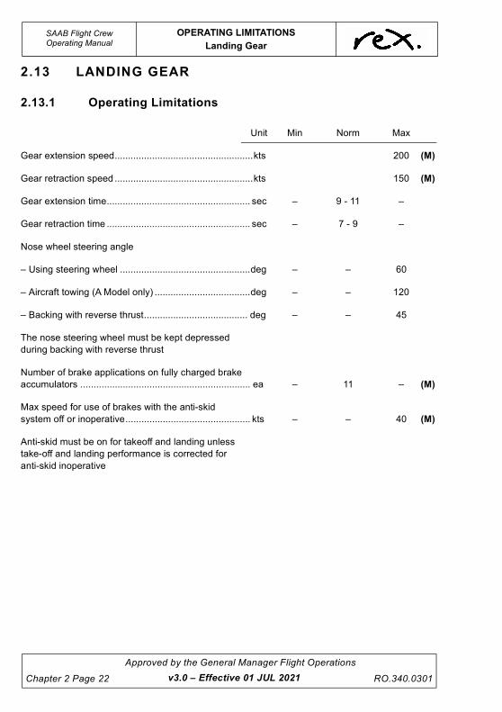
2.13 LANDING GEAR
2.13.1 Operating Limitations
Unit Min Norm Max
Gear extension speed....................................................kts 200 (M)
Gear retraction speed ....................................................kts 150 (M)
Gear extension time...................................................... sec – 9 - 11 –
Gear retraction time ...................................................... sec – 7 - 9 –
Nose wheel steering angle
– Using steering wheel .................................................deg – – 60
– Aircraft towing (A Model only) ....................................deg – – 120
– Backing with reverse thrust....................................... deg – – 45
The nose steering wheel must be kept depressed
during backing with reverse thrust
Number of brake applications on fully charged brake
accumulators ................................................................ ea – 11 – (M)
Max speed for use of brakes with the anti-skid
system off or inoperative............................................... kts – – 40 (M)
Anti-skid must be on for takeoff and landing unless
take-off and landing performance is corrected for
anti-skid inoperative
v3.0 – Effective 01 JUL 2021
UNCONTROLLED IF
REPRODUCED
OPERATING LIMITATIONS
Navigation, Attitude Heading System
SAAB Flight CrewOperating Manual
RO.340.0301
Approved by the General Manager Flight Operations
Chapter 2 Page 23
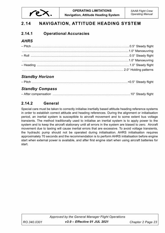
2.14 NAVIGATION, ATTITUDE HEADING SYSTEM
2.14.1 Operational Accuracies
AHRS
– Pitch ................................................................................................................0.5° Steady flight
..........................................................................................................................1.0° Manoeuvring
– Roll .................................................................................................................0.5° Steady flight
..........................................................................................................................1.0° Manoeuvring
– Heading ..........................................................................................................1.0° Steady flight
.................................................................................................................... 2.0° Holding patterns
Standby Horizon
– Pitch ..............................................................................................................<0.5° Steady flight
Standby Compass
– After compensation .........................................................................................10° Steady flight
2.14.2 General
Special care must be taken to correctly initialise inertially based attitude heading reference systems
in order to establish correct attitude and heading references. During the alignment or initialisation
period, an inertial system is susceptible to aircraft movement and to some extent bus voltage
transients. The method traditionally used to initialise an inertial system is to apply power to the
system and to keep the aircraft stationary until all errors in the system are biased to zero. Aircraft
movement due to taxiing will cause inertial errors that are excessive. To avoid voltage transients,
the hydraulic pump should not be operated during initialisation. AHRS initialisation requires
approximately 70 seconds and the recommendation is to perform AHRS initialisation before engine
start when external power is available, and after first engine start when using aircraft batteries for
start.
v3.0 – Effective 01 JUL 2021
UNCONTROLLED IF
REPRODUCED
SAAB Flight CrewOperating Manual
OPERATING LIMITATIONS
Power Plant
Chapter 2 Page 24
Approved by the General Manager Flight Operations
RO.340.0301
2.15 POWER PLANT
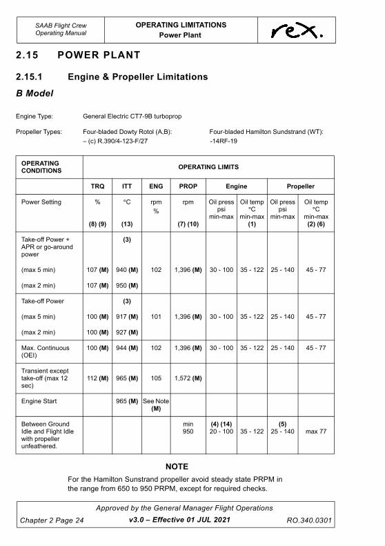
2.15.1 Engine & Propeller Limitations
B Model
NOTE
For the Hamilton Sunstrand propeller avoid steady state PRPM in
the range from 650 to 950 PRPM, except for required checks.
Engine Type: General Electric CT7-9B turboprop
Propeller Types: Four-bladed Dowty Rotol (A,B): Four-bladed Hamilton Sundstrand (WT):
– (c) R.390/4-123-F/27 -14RF-19
OPERATING CONDITIONS
OPERATING LIMITS
TRQ ITT ENG PROP Engine Propeller
Power Setting %
(8) (9)
°C
(13)
rpm
%
rpm
(7) (10)
Oil presspsi
min-max
Oil temp°C
min-max(1)
Oil presspsi
min-max
Oil temp°C
min-max(2) (6)
Take-off Power + APR or go-around power
(3)
(max 5 min) 107 (M) 940 (M) 102 1,396 (M) 30 - 100 35 - 122 25 - 140 45 - 77
(max 2 min) 107 (M) 950 (M)
Take-off Power (3)
(max 5 min) 100 (M) 917 (M) 101 1,396 (M) 30 - 100 35 - 122 25 - 140 45 - 77
(max 2 min) 100 (M) 927 (M)
Max. Continuous (OEI)
100 (M) 944 (M) 102 1,396 (M) 30 - 100 35 - 122 25 - 140 45 - 77
Transient except take-off (max 12 sec)
112 (M) 965 (M) 105 1,572 (M)
Engine Start 965 (M) See Note (M)
Between Ground Idle and Flight Idle with propeller unfeathered.
min950
(4) (14)20 - 100 35 - 122
(5)25 - 140 max 77
v3.0 – Effective 01 JUL 2021
UNCONTROLLED IF
REPRODUCED
OPERATING LIMITATIONS
Power Plant
SAAB Flight CrewOperating Manual
RO.340.0301
Approved by the General Manager Flight Operations
Chapter 2 Page 25
NOTE
The chart on the previous page shows the certification limits. It must
not be used for setting power.
(1) Max 132°C allowed for 15 minutes.
(2) Minimum oil temp + 25°C for ground operations, and after
take-off for max 5 minutes.
(3) Normal take-off ITT may be exceeded in accordance with
the “ITT Exceedance Program” (overleaf).
(4) Maximum 200 psi at starting and initial ground operation
with extremely cold oil.
(5) No operations above ground idle at 5 - 25 psi and 140 -
225 psi.
(6) Max 93°C allowed for 15 minutes.
(7) Prop RPM above 1396 indicates a propeller control
system anomally, although prop RPM up to 1456 is
allowed for up to one hour at up to Max Continuous
Power.
(8) Tq tolerance to selected CTOT value + 2%.
(9) Max Tq diff. between indications with CTOT selected ON 3%.
(10) It is normal that prop speed drops approx. 50 PRPM during
landing flare, due to aerodynamic load and decreased KIAS
i.e. in a normal case from 1384 to approx. 1350; however, in
an underspeed condition there is a possibility that the prop
speed will drop to below the bottoming governor speed (1040).
NOTE
(11) Allowable Oil Pressure Fluctuations 25 - 45 psi ....+ 5 psi
46 - 140 psi .... + 10 psi
(12) NG limitations for motoring start. (M)
* Max Ng for motoring - 26%
* Minimum stabilised Ng prior to Condition Lever to START- 17%
* Minimum Ng prior to Tailwind start - 20%.
(13) Max Allowable Fluctuation + 5oC
(14) ENG OIL PRESS warning (7psi) when the propeller is in the
feathered position can be disregarded without further action if the
warning can be cleared by moving the condition lever to the
unfeather position.
WARNING
It is prohibited to move the Power Lever(s) below FLIGHT
IDLE when airborne.
v3.0 – Effective 01 JUL 2021
UNCONTROLLED IF
REPRODUCED
SAAB Flight CrewOperating Manual
OPERATING LIMITATIONS
Power Plant
Chapter 2 Page 26
Approved by the General Manager Flight Operations
RO.340.0301 v3.0 – Effective 01 JUL 2021
CAUTION
During cold weather if the Power Levers are not advanced to
approximately 75% Tq the 64° PLA may not be met. For
temperatures below 0°C approximately 80% Tq is required. Tq
blooming over the Reduced Power Tq setting (up to rated) is
acceptable. When performing a Rated Power takeoff Tq
should be set 15 - 20% below the rated TRQ to ensure the
Rated Power is not exceeded.
Power Levers must be advanced to at least to 64° PLA as
indicated by the AFT base of the Power Levers passing the
yellow lines marked on the Power Lever Quadrant.
ITT Exceedance Program (B Model Only)
To minimise rejected take-offs and considering the safety ramifications of a high speed abort prior
to V1, a procedure has been established to deal with ITT exceedances during a take-off or go-
around with Normal Take-off Power.
If during take-off an incursion into the ITT range between 927°C/917°C and 944°C (Normal Take-
off ITT limit and MCP) occurs the take-off shall continue. The crew shall note the maximum ITT
observed. Additionally, the crew shall take an engine trend during the event flight’s cruise segment
and provide it to engineering for assessment on return to an engineering port.
If during a take-off 944°C is exceeded prior to V1, the take-off must be aborted.
If an exceedance between 944°C and 965°C for < 12 seconds occurs after V1, provided the engine
continues to operate normally the flight shall continue. The crew shall record the maximum ITT and
time at temperature observed. Additionally, the crew shall take an engine trend during the event
flight’s cruise segment and provide to engineering for assessment on return to an engineering port.
ITT exceedance above 965°C after V1 record maximum ITT and time at temperature. Return to
departure port and contact engineering.
NOTE
Any ITT exceedance above 965°C requires an engineering
inspection upon landing prior to further operation of the engine.
During OEI operations any ITT exceedance above Max Take-off Power + APR ITT (950°C/940°C)
record maximum ITT and time at temperature and notify engineering on landing.
UNCONTROLLED IF
REPRODUCED
OPERATING LIMITATIONS
Power Plant
SAAB Flight CrewOperating Manual
RO.340.0301
Approved by the General Manager Flight Operations
Chapter 2 Page 27
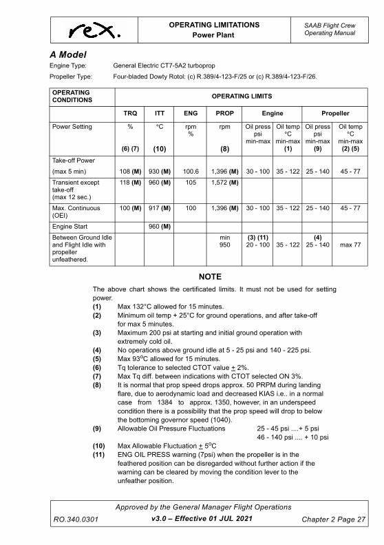
A Model
NOTE
The above chart shows the certificated limits. It must not be used for setting
power.
(1) Max 132°C allowed for 15 minutes.
(2) Minimum oil temp + 25°C for ground operations, and after take-off
for max 5 minutes.
(3) Maximum 200 psi at starting and initial ground operation with
extremely cold oil.
(4) No operations above ground idle at 5 - 25 psi and 140 - 225 psi.
(5) Max 93oC allowed for 15 minutes.
(6) Tq tolerance to selected CTOT value + 2%.
(7) Max Tq diff. between indications with CTOT selected ON 3%.
(8) It is normal that prop speed drops approx. 50 PRPM during landing
flare, due to aerodynamic load and decreased KIAS i.e.. in a normal
case from 1384 to approx. 1350, however, in an underspeed
condition there is a possibility that the prop speed will drop to below
the bottoming governor speed (1040).
(9) Allowable Oil Pressure Fluctuations 25 - 45 psi ....+ 5 psi
46 - 140 psi .... + 10 psi
(10) Max Allowable Fluctuation + 5oC
(11) ENG OIL PRESS warning (7psi) when the propeller is in the
feathered position can be disregarded without further action if the
warning can be cleared by moving the condition lever to the
unfeather position.
Engine Type: General Electric CT7-5A2 turboprop
Propeller Type: Four-bladed Dowty Rotol: (c) R.389/4-123-F/25 or (c) R.389/4-123-F/26.
OPERATING CONDITIONS
OPERATING LIMITS
TRQ ITT ENG PROP Engine Propeller
Power Setting %
(6) (7)
°C
(10)
rpm%
rpm
(8)
Oil presspsi
min-max
Oil temp°C
min-max(1)
Oil presspsi
min-max (9)
Oil temp°C
min-max(2) (5)
Take-off Power
(max 5 min) 108 (M) 930 (M) 100.6 1,396 (M) 30 - 100 35 - 122 25 - 140 45 - 77
Transient except take-off (max 12 sec.)
118 (M) 960 (M) 105 1,572 (M)
Max. Continuous (OEI)
100 (M) 917 (M) 100 1,396 (M) 30 - 100 35 - 122 25 - 140 45 - 77
Engine Start 960 (M)
Between Ground Idle and Flight Idle with propeller unfeathered.
min950
(3) (11)20 - 100 35 - 122
(4)25 - 140 max 77
v3.0 – Effective 01 JUL 2021
UNCONTROLLED IF
REPRODUCED
SAAB Flight CrewOperating Manual
OPERATING LIMITATIONS
Power Plant
Chapter 2 Page 28
Approved by the General Manager Flight Operations
RO.340.0301 v3.0 – Effective 01 JUL 2021
WARNING
It is prohibited to move the Power Lever(s) below FLIGHT
IDLE when airborne.
CAUTION
During cold weather if the Power Levers are not advanced to
approximately 75% TRQ the 64°C PLA may not be met. For
temperatures below 0° approximately 80% TRQ is required.
TRQ blooming over the Reduced Power TRQ setting (up to
rated) is acceptable. When performing a Rated Power takeoff
TRQ should be set 15 - 20% below the rated TRQ to ensure
the Rated Power is not exceeded.
Power Levers must be advanced to at least to 64° PLA as
indicated by the AFT base of the Power Levers passing the
yellow lines marked on the Power Lever Quadrant.
2.15.2 Maximum Continuous Power (MCP)
NOTE
Maximum Contiuous Power is provided for one engine operation
and if required, for two engine operation in extreme icing
conditions. It is NOT intended for use during normal icing
conditions, climb expedites from ATC, etc.
However, the statement above should not prevent the pilot from
using the power deemed required in an emergency or abnormal
situation or from using the power required to prevent such a
situation from developing.
NOTE
Prop RPM up to 1396 is allowed with condition levers in MAX.
However the Prop RPM shall be reduced to Max 1384 by CL
adjustment.
UNCONTROLLED IF
REPRODUCED
OPERATING LIMITATIONS
Power Plant
SAAB Flight CrewOperating Manual
RO.340.0301
Approved by the General Manager Flight Operations
Chapter 2 Page 29
2.15.3 Oil System
Engine Oil Consumption Limit (Maximum)
1 litre/7.5 hrs.
Two (2) quarts may be added to bring the oil quantity level on the sight gauge from ADD to FULL.
Wait a minimum of 10 minutes after engine shutdown to allow oil to drain back into the tank before
checking the oil tank level indicator.
PGB Oil Consumption Limit (Maximum)
1 litre/29 hrs.
One (1) quart may be added to bring the oil quantity level on the sight gauge from ADD to FULL.
Wait a minimum of 3 minutes after engine shutdown to allow oil to drain from the lines before
checking the oil tank level indicator.
CAUTION
Do not operate the engine if any of the oil consumption limits
are exceeded.
2.15.4 Approved Type Of Oil (Engine and PGB)
CAUTION
Minimum oil temperature for engine start is – 40°C.
Exxon Turbo oil 2380 (this is the only oil used by Rex).
2.15.5 Miscellaneous Limitations
WARNING
It is prohibited to move the power lever(s) below FLIGHT IDLE
when airborne. If the PL is moved below flight idle when
airborne, the propeller will go into low pitch angle, the
propeller speed will increase uncontrolled with extremely
high drag, possible uncontrolled flight, engine shutdown and
loss of engine power. (M)
When airborne, grip the PL knobs only, thereby eliminating PL movement to below FLT IDLE
v3.0 – Effective 01 JUL 2021
UNCONTROLLED IF
REPRODUCED
SAAB Flight CrewOperating Manual
OPERATING LIMITATIONS
Power Plant
Chapter 2 Page 30
Approved by the General Manager Flight Operations
RO.340.0301 v3.0 – Effective 01 JUL 2021
2.15.6 Starter/Generator (S/G) Duty Cycle Limits.
• Starter Duty Cycle:
– Two start attempts with 3 minutes cooling between, then 25 minutes cooling before
subsequent starts. (M)
• Motoring:
– Three 30-second ventilations with 3 minutes cooling between each, then a
one-hour cooling period before subsequent starts or motoring. (M)
• Time to light-off (from initial Ng rotation to ITT rise), 20 seconds maximum (direct start
only). (M)
• Maximum time with starter engaged is 70 seconds of which max 30 seconds plain
motoring. (M)
UNCONTROLLED IF
REPRODUCED
OPERATING LIMITATIONS
Runway Requirements
SAAB Flight CrewOperating Manual
RO.340.0301
Approved by the General Manager Flight Operations
Chapter 2 Page 31
2.16 RUNWAY REQUIREMENTS
2.16.1 Width
Minimum runway width is 30 metres of rated surface (see information on ACN and PCN numbers
below).
2.16.2 Pavement Classification Number (PCN)
To assess the suitability of a particular runway for use by the SAAB 340 aircraft, obtain the PCN
(Pavement Classification Number) from the Jeppesen Airport Directory. The PCN number is
always followed by an “R” for rigid pavement or an “F” for flexible pavement. In addition, the
pavement is graded according to strength from “A” to “D” as shown below.
After the “R” or “F” there will be an A, B, C or D, which means:
The last letter is either "T" or "U"
Having established into which category a particular runway falls, obtain from the table below, the
ACN (Aircraft Classification Number). The aircraft must not use a runway unless the ACN is equal
to or less than the PCN and the aircraft tyre pressure is equal to or less than the figure quoted in
the Jeppesen Airport Directory.
NOTE
Some airports in the Rex RPT network do not meet the
specifications for SAAB operations as per the above. In these
instances the appropriate authorities have granted dispensation.
A = High Strength
B = Medium Strength
C = Low Strength
D = Ultra Low Strength
followed by the maximum allowable tyre pressure in kilopascals (and psi).
T = Technical evaluation, representing a specific study of the pavement characteristics and
application of pavement behaviour technology.
U = Using aircraft experience, representing knowledge of the specific type and mass of aircraft
satisfactorily being supported under regular use.
v3.0 – Effective 01 JUL 2021
UNCONTROLLED IF
REPRODUCED
SAAB Flight CrewOperating Manual
OPERATING LIMITATIONS
Runway Requirements
Chapter 2 Page 32
Approved by the General Manager Flight Operations
RO.340.0301 v3.0 – Effective 01 JUL 2021
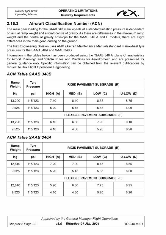
2.16.3 Aircraft Classification Number (ACN)
The main gear loading for the SAAB 340 main wheels at a standard inflation pressure is dependant
on actual ramp weight and aircraft centre of gravity. As there are differences in the maximum ramp
weight and the centre of gravity envelope for the SAAB 340 A and B models, there are slight
differences in the main gear loading on the ground.
The Rex Engineering Division uses AMM (Aircraft Maintenance Manual) standard main-wheel tyre
pressures for the SAAB 340A and SAAB 340B.
Information in the tables below has been produced using the “SAAB 340 Airplane Characteristics
for Airport Planning” and “CASA Rules and Practices for Aerodromes”, and are presented for
general guidance only. Specific information can be obtained from the relevant publications by
request to Rex Flight Operations Engineering.
ACN Table SAAB 340B
ACN Table SAAB 340A
Ramp
Weight
Tyre
PressureRIGID PAVEMENT SUBGRADE (R)
Kg psi HIGH (A) MED (B) LOW (C) U-LOW (D)
13,290 115/123 7.40 8.10 8.35 8.75
9,525 115/123 5.20 5.45 5.85 6.00
FLEXIBLE PAVEMENT SUBGRADE (F)
13,290 115/123 6.10 6.80 7.90 9.10
9,525 115/123 4.10 4.60 5.20 6.20
Ramp
Weight
Tyre
PressureRIGID PAVEMENT SUBGRADE (R)
Kg psi HIGH (A) MED (B) LOW (C) U-LOW (D)
12,840 115/123 7.20 7.90 8.15 8.55
9,525 115/123 5.20 5.45 5.85 6.00
FLEXIBLE PAVEMENT SUBGRADE (F)
12,840 115/123 5.90 6.80 7.75 8.95
9,525 115/123 4.10 4.60 5.20 6.20
UNCONTROLLED IF
REPRODUCED
OPERATING LIMITATIONS
Runway Requirements
SAAB Flight CrewOperating Manual
RO.340.0301
Approved by the General Manager Flight Operations
Chapter 2 Page 33v3.0 – Effective 01 JUL 2021
2.16.4 Operations on Unpaved Runways
General
Take-off and landing of this aircraft on unpaved runways is approved if Company Performance
Data is available.
Limitations
1. Unpaved runway operations are not approved for ZPA, ZPB, ZPC, ZXF, ZXG, ZXK.
2. The runway surface shall be gravel, short grass or compacted clay.
3. Operations on wet grass covered surfaces, wet clay surfaces, or gravel surfaces with
standing water are not approved.
4. The runway surface shall be hard, graded smooth and free from ruts, pot holes and
troughs.
NOTE
Operations on WET gravel runways are approved provided there
is no standing water. As there is no difference in braking
effectiveness on WET and DRY gravel runways DRY data may be
used to calculate performance figures on WET gravel runways.
Normal Procedures
• On take-off, power should be applied sufficiently slowly to avoid the risk of damage to
propellers, engines and airframe. This precaution is not required if the take-off run is
commenced on a paved surface.
• Only Flap 15 shall be used for take-off. Only Flap 20 shall be used for landing.
• Reverse thrust may be used on landing but should be avoided in accordance with normal
Company procedures remembering that additional damage may be caused by loose
material.
• Reverse thrust may be used during a rejected take-off.
Post Flight Inspection and Notation of Daily Flight Log
Crew are required to carry out the normal Post Flight Inspection paying particular attention to the
areas highlighted below after landing on an unpaved runway and after landing post departure from
an unpaved runway.
• Lower Flap Surface for punctures.
• Lower Antennas for excessive stone damage.
• Lower Beacon for damage.
• Propellers for excessive blade damage.
• Tyres / sidewalls for cuts.
• Brakes for any damage or broken brake lines or leakage.
A notation must then be made in the "Remarks" column of the Daily Flight Log stating "Inspected
OK"

UNCONTROLLED IF
REPRODUCED
This page intentionally left blank.