Embed Size (px)
Citation preview

All information is subject to change without notice. Rev: 20.0
http://www.spartanchassis.com
1-800-543-4277 option 1 Page 1 of 65

All information is subject to change without notice. Rev: 20.0
http://www.spartanchassis.com
1-800-543-4277 option 1 Page 2 of 65
SPARTAN MOTORS USA, INC. (SPARTAN) OPERATION AND MAINTENANCE MANUAL
for MOTORHOMES
Every effort has been made to ensure accuracy and quality in publication of this document.
At the time of printing, content is the most current available.
Due to technological advancements, continuous
improvement of our products and the products of our component suppliers, Spartan Motors USA, Inc. reserves the right to change specifications without notification.
Spartan Motors USA, Inc. 1541 Reynolds Rd.
Charlotte, MI 48813 USA
1-517-543-6400
http://www.spartanchassis.com

All information is subject to change without notice. Rev: 20.0
http://www.spartanchassis.com
1-800-543-4277 option 1 Page 3 of 65
Dear Valued Spartan Owner: Everyone at Spartan Motors USA, Inc. would like to express a sincere thank you for your recent purchase of a premium motorhome featuring our custom engineered and manufactured chassis. This manual describes proper use and maintenance of your chassis, which will help assure your safety and years of trouble free operation. Please take time to read all of the sections of the manual in detail. This is information that every owner/operator should know. Component information from certain suppliers is located after Section 9 of this manual. This information may be useful in understanding special features, maintenance requirements, and operating instructions for many of the major components and systems that are part of your chassis. Once again, “Thank You” for selecting a premium motorhome featuring a world class custom chassis from Spartan. If at any time you have questions pertaining to your chassis, please contact the Spartan Customer & Product Support at 1-800-543-4277 Option #1 or visit our web site at www.spartanchassis.com. Sincerely, Spartan Motors USA, Inc.

All information is subject to change without notice. Rev: 20.0
http://www.spartanchassis.com
1-800-543-4277 option 1 Page 4 of 65
TABLE OF CONTENTS

All information is subject to change without notice. Rev: 20.0
http://www.spartanchassis.com
1-800-543-4277 option 1 Page 5 of 65
Not all information contained in this manual may pertain to your vehicle. If you have any questions about the operation of your chassis or the manual, please contact Spartan Customer & Product Support Center: 1-800-543-4277 Option #1.
TABLE OF CONTENTS
1.0 INTRODUCTION .................................................................................................................................... 9
INTRODUCTION ................................................................................................................................... 10
CUSTOMER & PRODUCT SUPPORT ..................................................................................................... 10
SPARTAN MOTORS USA, INC. CUSTOMER & PRODUCT SUPPORT GROUP……1-800-543-4277 ......... 10
FAX 1-517-543-9264 ..................................................................................................................... 10
SPARTAN MOTORS USA, INC. SERVICE PARTS 1-800-722-3025 ...................................................... 10
SAFETY ALERTS .................................................................................................................................... 10
CHASSIS / BODY INTERFACE ................................................................................................................ 10
MAINTENANCE RECORDS ................................................................................................................... 11
REPORTING SAFETY DEFECTS .............................................................................................................. 11
2.0 GENERAL INFORMATION ................................................................................................................... 12
CHASSIS WARRANTY AND REGISTRATION .......................................................................................... 13
LIMITED WARRANTY COVERS ............................................................................................................. 13
VEHICLE IDENTIFICATION NUMBER .................................................................................................... 14
CHASSIS / VEHICLE WEIGHT INFORMATION ....................................................................................... 14
GROSS VEHICLE WEIGHT RATING (GVWR) ......................................................................................... 14
GROSS VEHICLE WEIGHT (GVW) ......................................................................................................... 14
GROSS AXLE WEIGHT RATING (GAWR) ............................................................................................... 14
GROSS AXLE WEIGHT (GAW) .............................................................................................................. 15
GROSS COMBINATION WEIGHT RATING (GCWR) AND TOWING ....................................................... 15
WHEN YOUR VEHICLE NEEDS SERVICE ............................................................................................... 16
GENERAL SAFETY PRECAUTIONS ........................................................................................................ 16
3.0 CHASSIS GETTING STARTED ............................................................................................................... 17
GETTING STARTED .............................................................................................................................. 18
GENERAL START-UP AND PARKING PROCEDURES .............................................................................. 18
Starting the Vehicle ....................................................................................................................... 18
Parking the Vehicle ....................................................................................................................... 19
BEFORE YOU GET BEHIND THE WHEEL ............................................................................................... 19
CHASSIS STORAGE AND PERIODS OF NON-USE .................................................................................. 19
CHASSIS SAFETY INSPECTIONS AND MAINTENANCE .......................................................................... 20
RECOMMENDED DAILY DRIVER’S INSPECTION ................................................................................... 20
CHASSIS PRE-TRIP INSPECTION ........................................................................................................... 21
4.0 ELECTRICAL ......................................................................................................................................... 22
ELECTRICAL .......................................................................................................................................... 23
MEMORY OPTIONS ............................................................................................................................. 23
Set Driver “POS 1” and “POS 2” Memory: .................................................................................... 23
To Set EXIT/“POS 3” Memory: ...................................................................................................... 23

All information is subject to change without notice. Rev: 20.0
http://www.spartanchassis.com
1-800-543-4277 option 1 Page 6 of 65
To Recall Settings: ......................................................................................................................... 23
ENGINE CONTROLS ............................................................................................................................. 24
Ignition Switch .............................................................................................................................. 24
Accelerator Pedal .......................................................................................................................... 24
Cruise Control and Idle Control .................................................................................................... 24
STEERING WHEEL AND COLUMN CONTROLS ..................................................................................... 26
Hazard Warning System ................................................................................................................ 26
Turn Signal Lever, High/Low Headlamp Beam, (Non-Smart Wheel Only) Cruise/Idle Control .... 26
Tilt Wheel and Telescopic Column Controls ................................................................................. 26
STEERING WHEEL CONTROLS ............................................................................................................. 27
Headlamp Flash ............................................................................................................................. 27
Daytime Running Lamps ............................................................................................................... 27
Marker Lamp Flash ........................................................................................................................ 27
Cruise and Idle Control Functions ................................................................................................. 27
Wiper Control Functions ............................................................................................................... 27
Wiper High / Low .......................................................................................................................... 27
Wiper Wash................................................................................................................................... 27
Wiper Variable Display .................................................................................................................. 27
Tilt (Memory Power Column) ....................................................................................................... 28
Telescope Column (Memory Power Column) ............................................................................... 28
Pedals (Memory Power Column) .................................................................................................. 28
TELLTALES............................................................................................................................................ 29
CRITICAL SYSTEM TELLTALES .............................................................................................................. 29
Telltales ......................................................................................................................................... 29
ADDITIONAL TELLTALES ...................................................................................................................... 29
GAUGES ............................................................................................................................................... 30
AIRFLOW RESTRICTION GAUGE .......................................................................................................... 30
AIR PRESSURE GAUGE ......................................................................................................................... 30
ENGINE COOLANT TEMPERATURE GAUGE ......................................................................................... 31
ENGINE FUEL LEVEL GAUGE ................................................................................................................ 31
TRANSMISSION FLUID TEMPERATURE GAUGE ................................................................................... 31
ENGINE OIL PRESSURE GAUGE ........................................................................................................... 31
VOLTMETER......................................................................................................................................... 32
TACHOMETER...................................................................................................................................... 32
DIESEL EXHAUST FLUID ....................................................................................................................... 32
SPEEDOMETER .................................................................................................................................... 32
DIESEL EXHAUST FLUID ....................................................................................................................... 33
ELECTRICAL .......................................................................................................................................... 34
Chassis Batteries ........................................................................................................................... 34
Fuse Panels/Boxes ........................................................................................................................ 34
Powertrain/Chassis Fuse Locations .............................................................................................. 35
On Board Diagnostic (OBD) (If Equipped) ..................................................................................... 36
Owners/Operators: ....................................................................................................................... 36
Malfunction Indicator Lamp (MIL) (If Equipped) .......................................................................... 36
All information is subject to change without notice. Rev: 20.0
http://www.spartanchassis.com
1-800-543-4277 option 1 Page 7 of 65
On-Board Weighing System (OBWS) (If Equipped) ....................................................................... 36
Weighing ....................................................................................................................................... 37
Calibration ..................................................................................................................................... 37
5.0 ENGINE ................................................................................................................................................ 38
ENGINE ................................................................................................................................................ 39
Air Intake Tubing ........................................................................................................................... 39
Airflow Restriction Gauge ............................................................................................................. 39
Coolant Hoses, Pipes/Tubes, Clamps ............................................................................................ 39
Radiator/Charge Air Cooler ........................................................................................................... 39
Engine Cooling Fan ........................................................................................................................ 39
Engine Coolant Level ..................................................................................................................... 39
Coolant Maintenance ................................................................................................................... 40
Fuel/Water Separator ................................................................................................................... 40
Engine Drive and Accessory Belts ................................................................................................. 40
Lubricating Oil ............................................................................................................................... 40
MECHANICAL FAN DRIVE GEAR BOX .................................................................................................. 41
FAN BELT TENSIONING GUIDELINES FOR K3 CHASSIS (ONLY) ............................................................ 41
AFTERTREATMENT SYSTEM ................................................................................................................ 42
6.0 TRANSMISSION ................................................................................................................................... 44
TRANSMISSION ................................................................................................................................... 45
Fluid Level ..................................................................................................................................... 45
TRANSMISSION SHIFT SELECTOR ........................................................................................................ 45
7.0 AXLES/WHEELS & TIRES ..................................................................................................................... 46
TIRES AND WHEELS ............................................................................................................................. 47
Air Pressure ................................................................................................................................... 47
ROLLING RESISTANCE .......................................................................................................................... 47
TIRE PRESSURE MONITORING SYSTEM ............................................................................................... 47
Condition ....................................................................................................................................... 47
Wheel Nuts ................................................................................................................................... 48
TIRE SPEED RATING ............................................................................................................................. 48
AXLES ................................................................................................................................................... 48
Hub Covers .................................................................................................................................... 48
Front Axle ...................................................................................................................................... 49
Rear Axle ....................................................................................................................................... 49
VEHICLE WEIGHT ................................................................................................................................. 49
Vehicle Weight Worksheet ........................................................................................................... 49
8.0 STEERING, BRAKES, AND SUSPENSION.............................................................................................. 51
CHASSIS SYSTEMS ............................................................................................................................... 52
AIR SUSPENSION DUMP SYSTEMS ...................................................................................................... 52
Chassis Suspension Dump Systems (optional) .............................................................................. 52
Tag Axle Suspension Dump System .............................................................................................. 52
Manual Control ............................................................................................................................. 52
Automatic Control ......................................................................................................................... 53
Hadley® SAMS/Smart Air Management System ........................................................................... 53

All information is subject to change without notice. Rev: 20.0
http://www.spartanchassis.com
1-800-543-4277 option 1 Page 8 of 65
Hadley® SLS/ Self Leveling System ................................................................................................ 53
BRAKE SYSTEM AND CONTROLS ......................................................................................................... 53
Service Brakes ............................................................................................................................... 53
ABS ................................................................................................................................................ 53
Automatic Traction Control (ATC)................................................................................................. 53
Full Air Brake System .................................................................................................................... 53
Parking Brakes (Spring Brakes) ..................................................................................................... 54
BRAKES ................................................................................................................................................ 54
Parking Brake Operation ............................................................................................................... 54
Service Brake Operation ............................................................................................................... 54
COMPRESSED AIR SYSTEM .................................................................................................................. 55
Air System/Air Dryer Operation .................................................................................................... 55
Moisture Ejectors and Air Tank Petcocks ..................................................................................... 55
STEERING ............................................................................................................................................. 56
Hydraulic System........................................................................................................................... 56
Steering Gear / Linkage ................................................................................................................. 56
SUSPENSION ........................................................................................................................................ 56
Rear Air Front and Springs / Ride Height ...................................................................................... 56
Shocks ........................................................................................................................................... 56
CHASSIS MAINTENANCE ..................................................................................................................... 57
CHASSIS MAINTENANCE GUIDE / RECORDKEEPING ........................................................................... 57
APPENDIX A ......................................................................................................................................... 58
PRE-TRIP INSPECTION ITEMS .............................................................................................................. 60
CHASSIS RIDE HEIGHT SPECIFICATIONS .............................................................................................. 62
K3 SERIES CHASSIS .............................................................................................................................. 62
K2 SERIES CHASSIS .............................................................................................................................. 62
MM and NVS SERIES CHASSIS ............................................................................................................. 62
9.0 INDEX .................................................................................................................................................. 64

All information is subject to change without notice. Rev: 20.0
http://www.spartanchassis.com
1-800-543-4277 option 1 Page 9 of 65
1.0 INTRODUCTION

All information is subject to change without notice. Rev: 20.0
http://www.spartanchassis.com
1-800-543-4277 option 1 Page 10 of 65
THIS MANUAL SHOULD ALWAYS REMAIN WITH THE CHASSIS/VEHICLE AND BE EASILY ACCESSIBLE TO THE OPERATOR AND THE SERVICE CENTER.
INTRODUCTION
The Chassis Operation and Maintenance Manual is intended to enhance the overall vehicle ownership experience by providing the end-user with important information to safely operate the chassis, and realize optimum performance from the chassis systems. Before operating the chassis, read this manual and any other instructional material provided by the Final Stage Manufacturer and/or Dealer. If for any reason the information in this manual seems unclear, or if you have a question regarding your chassis, please contact the Spartan Customer & Product Support Group at one of the numbers listed below. We welcome your comments on how we can better serve you by improving our products and services.
CUSTOMER & PRODUCT SUPPORT
SPARTAN MOTORS USA, INC. CUSTOMER & PRODUCT SUPPORT GROUP…………….1-800-543-4277
FAX ........................................................................................................ 1-517-543-9264
SPARTAN MOTORS USA, INC. SERVICE PARTS .................................................. 1-800-722-3025
SAFETY ALERTS
Safety alerts are presented in this manual with the following symbol describing the safety risks and potential outcome for each type of alert.
This symbol is used to address practices not related to personal injury.
A hazardous condition exists that may result in minor to moderate injury, property damage or destruction if instructions are not strictly observed.
A potentially hazardous condition exists that may result in death or serious injury, property damage, or destruction if instructions are not strictly observed.
CHASSIS / BODY INTERFACE
As a custom manufacturer of cab and chassis products, Spartan is committed to providing a high quality product to our customers. Spartan works closely with Final Stage Manufacturers to ensure system integrity is preserved and the retail purchaser are presented with a quality product. It is important to understand that not all information in this manual will apply to every unit manufactured since some features are optional.
Refer to the appropriate Final Stage Manufacturer’s literature for additional information. Guidelines for Body interface requirements are provided to our Final Stage Manufacturer’s as published in the Motorhome Body Builders Manual.

All information is subject to change without notice. Rev: 20.0
http://www.spartanchassis.com
1-800-543-4277 option 1 Page 11 of 65
MAINTENANCE RECORDS
It is the owner’s responsibility to keep accurate maintenance and repair records, including receipts. Should the lack of required maintenance be the reason for repair, a warranty claim will not be accepted. Spartan reserves the right to request your maintenance and repair records for verification of compliance with required maintenance practices and intervals. Maintenance interval and record keeping information is available in the Appendix of this manual.
Spartan recommends that the maintenance and repair records/receipts be maintained in your permanent records and transferred to any subsequent vehicle owner. Acceptable records include itemized bills, dealer work orders, owner’s vehicle log, and service facility receipts, which must state the date service was performed, mileage (kilometers), Vehicle Identification Number, and service performed.
REPORTING SAFETY DEFECTS
If you believe that your vehicle has a defect, which could cause a crash, injury, or death, you should immediately advise Spartan Customer & Product Support Group, the National Highway Traffic Safety Administration (NHTSA), and/or Environmental Protection Agency.
NHTSA cannot become involved with individual issues between the customer and the dealer or any Spartan subsidiary. However, if NHTSA receives similar complaints, an investigation may be opened to study the possibility of a safety defect that may exist in a group of vehicles. Should a defect be confirmed, a recall or remedy campaign may be ordered.
To contact NHTSA, call the Auto Safety Hotline toll free at 1-888-327-4236, write to: U.S. Department of Transportation, National Highway Traffic Safety Administration, Office of Defects Investigation, NVS-216, 1200 New Jersey Avenue, SE Washington, DC 20590 or to file a complaint online: http://www-odi.nhtsa.dot.gov/ivoq/ To contact Environmental Protection Agency: Director Field Operations and Support Division Environmental Protection Agency 401 “M” Street SW., Washington, DC 204620 Attention: Warranty Claim

All information is subject to change without notice. Rev: 20.0
http://www.spartanchassis.com
1-800-543-4277 option 1 Page 12 of 65
2.0 GENERAL INFORMATION

All information is subject to change without notice. Rev: 20.0
http://www.spartanchassis.com
1-800-543-4277 option 1 Page 13 of 65
If you have a question regarding your chassis, or this manual, please contact the Spartan Customer & Product Support Group at 1-800-543-4277 Option #1.
CHASSIS WARRANTY AND REGISTRATION
The prompt return of the Limited Warranty Registration in this manual will allow servicing of the chassis under warranty, should a warrantable condition exist. The most effective way to submit our Chassis Registration Form is through our website, www.spartanchassis.com, under the customer & product support tab. If a computer is not available, complete the paper form and mail to the address below.
Spartan Motors USA, Inc.
Customer & Product Support 1541 Reynolds Rd.
Charlotte, MI. 48813
THE CHASSIS LIMITED WARRANTY IS NOT VALID, AND REMAINS NULL AND VOID, IF THE LIMITED WARRANTY REGISTRATION FORM IS NOT RETURNED WITHIN (30) DAYS AFTER THE DATE OF RETAIL PURCHASE. IF YOU ARE NOT SURE WHETHER YOUR WARRANTY IS STILL IN EFFECT, OR HAVE OTHER QUESTIONS ABOUT WARRANTY COVERAGE, PLEASE CONTACT THE SPARTAN CUSTOMER & PRODUCT SUPPORT GROUP AT 1-800-543-4277.
LIMITED WARRANTY COVERS The limited warranty covers repair or replacement, at the sole option of Spartan Motors USA, Inc. (hereinafter Spartan), of any part of your new Spartan chassis (hereinafter Covered Parts) in which a defect in materials or workmanship appears during normal use, maintenance or service within the limited warranty period, subject to certain limitations and exclusions described in the limited warranty. REPAIR OR REPLACEMENT OF COVERED PARTS BY A SPARTAN AUTHORIZED SERVICE CENTER IS THE EXCLUSIVE REMEDY UNDER THE LIMITED WARRANTY. SPARTAN WILL NOT REPLACE THE MOTORHOME OR REPURCHASE THE MOTORHOME FROM YOU. The repair or replacement of a Covered Part does not extend the life of the limited warranty except where state or provincial law otherwise provides for an extension during the time that the Covered Part is being repaired or replaced under the limited warranty. Covered Parts are limited to chassis systems and components such as the driveline, cooling system, hydraulic system, suspension, air system, and structural systems (frame and supporting hardware). The chassis limited warranty excludes the engine, certain emissions components, and transmission or any parts or components added to the chassis by another party. In addition to the Spartan limited warranty, original component manufacturers may provide their own warranties. Purchasers should check the original component manufacturer’s warranty regarding its coverage. The limited warranty is valid only in the United States and Canada. For more detailed information refer to the warranty section of this manual.
Certain components of the emissions control system have a 5 year/100,000 mile warranty, whichever comes first. Contact Spartan if you have questions regarding this warranty.
Tires will have a warranty of 2 years/24,000 miles whichever comes first. Contact Spartan if you have questions regarding tire related warranty.

All information is subject to change without notice. Rev: 20.0
http://www.spartanchassis.com
1-800-543-4277 option 1 Page 14 of 65
VEHICLE IDENTIFICATION NUMBER Every chassis manufactured by Spartan is assigned a unique VIN (Vehicle Identification Number) that is used as both the chassis and vehicle serial number. It is displayed, at minimum, on a certification label provided by the final manufacturer. Refer to the Final Stage Manufacturer’s literature for certification label location and additional VIN information.
When filing a warranty claim, submitting a complaint, or general inquiries, you will need to provide the last eight digits of the vehicle identification number (VIN) as stated on the label.
CHASSIS / VEHICLE WEIGHT INFORMATION
It is important for the vehicle operator to understand the weight rating terminology as described below. For safety and proper chassis function, it is critical that:
The actual, fully loaded vehicle weights are known for each tire position. Refer to the Gross Axle Weight section of this manual for additional information.
The axle and tire/wheel weight ratings are not exceeded.
Proper tire pressures are maintained. For the most current tire inflation information, refer to the respective tire manufacturer’s website for downloadable inflation tables. Goodyear Website: http://www.goodyear.com/rv/ Michelin Website: http://www.michelinrvtires.com/michelinrv/index.jsp
The major chassis components supporting the vehicle are not to be changed or replaced by components with lower ratings (e.g. tires).
In Section 7 of this manual, a weight record worksheet is provided to assist with properly weighing your vehicle and recording important data.
GROSS VEHICLE WEIGHT RATING (GVWR)
The GVWR is the rating established by Spartan as the maximum weight of the vehicle (including cargo, passengers, liquids, etc.) that the components of the vehicle are designed to support. This rating excludes any towed item.
GROSS VEHICLE WEIGHT (GVW)
The GVW is the total actual weight of a fully loaded vehicle. This includes the vehicle, cargo, passengers, and any liquids/fuels. This weight excludes any towed item. The GVW must not exceed the GVWR.
GROSS AXLE WEIGHT RATING (GAWR)
The GAWR is the maximum weight rating that an axle assembly is designed to support. Axle assembly components include the axle, suspension, tires, wheels, and brakes.

All information is subject to change without notice. Rev: 20.0
http://www.spartanchassis.com
1-800-543-4277 option 1 Page 15 of 65
GROSS AXLE WEIGHT (GAW)
The GAW is the total actual weight supported by a single axle, when the vehicle is fully loaded. The GAW of each axle must not exceed the corresponding GAWR for the axle. Weight distribution on an axle must be as equal side-to-side as possible to avoid overloading one side. Therefore, individual wheel position weights must be taken to avoid this condition. If the weight on one side of an axle exceeds the weight on the other side of that same axle by more than 5% of the total axle rating (GAWR), it is necessary to redistribute the load appropriately. For example, if the GAWR of one axle on your vehicle is 10,000 pounds, 5% of that is 500 pounds. This means that the actual weight difference between the left and right side of the axle must be within 500 pounds. In addition, the actual weight on one side of a single axle must never exceed 50% or one half of the GAWR for that axle, which would be 5,000 pounds for the preceding example. Refer to the axle manufacturer’s literature for additional information.
GROSS COMBINATION WEIGHT RATING (GCWR) AND TOWING
The GCWR is the maximum total weight rating allowed for a vehicle and any attachment, such as a trailer or towed vehicle. To determine the total allowable weight for a towed item, subtract the GVWR from the GCWR.
The minimum rating of both drop ball mount and receiver ball must be equal to or greater than towed vehicle rated capacity. Allowable extension and drop combinations are shown in Table 2-1. Exceeding these dimensions will cause the hitch to be overloaded beyond rated limits at maximum hitch capacity refer to FIG. 2-2. For use of unpublished combinations, contact Spartan engineering for approval.
When towing, two safety chains must be used with both chains and hooks capable of rated towing limit. To clarify, total safety chain capacity must be double the rated towing limit.
The maximum recommended tongue load (vertical load) on the ball drop is 10% of rated towing capacity. Load redistribution will be required if tongue load is exceeded even if rated pulling capacity (horizontal) is not exceeded.
The use of weight distribution bars is not recommended unless specifically noted on the WEIGHT DISTRIBUTING RATING label on the hitch.
The chassis braking system is rated for operation at the GVWR – NOT the GCWR. Separate functional brake systems should be used for safe control of towed vehicles or trailers. It is important for you to understand if there are any government (federal, state, local, or other) regulations that apply to weight restrictions for the areas you plan to travel. Government restrictions could affect the size and weight of the towed item and whether an auxiliary braking system is required.
Table 2-1 Allowable ball mount extension and drop.
Gross Trailer Weight Rating Extension Drop
15,000 pounds or below Up to 10.00” 0.00”- 4.00”
Above 15,000 pounds Up to 8.50” 0.00”- 4.00”

All information is subject to change without notice. Rev: 20.0
http://www.spartanchassis.com
1-800-543-4277 option 1 Page 16 of 65
WHEN YOUR VEHICLE NEEDS SERVICE
You should advise the service facility that this manual includes important inspection and maintenance information. It should be made accessible to the technician when inspection, maintenance, and/or service are needed.
Inherent dangers exist when performing work on a chassis. To reduce risk of personal injury, engage the services of a professional technician at an authorized service facility.
When performing vehicle inspections or maintenance, always wear protective clothing, safety glasses, and follow all component manufacturer safety guidelines.
GENERAL SAFETY PRECAUTIONS
Always wear protective clothing and safety glasses.
Do not wear jewelry, loose, or torn clothing.
Always engage the park brake unless noted otherwise.
Never work on the vehicle when the engine is running.
Disconnect both of the main CHASSIS battery cables: (1) negative and (1) positive. Prior to disconnecting the battery cables, ensure the unit has been off at least 70 seconds and disconnect the positive cable first.
Do not work on a vehicle supported ONLY by jack stands, floor jacks, lifting stands, or a hoist. Use blocks or chocks to secure all wheel positions.
Follow the component manufacturer’s safety instructions.
Trailer Hitch Extension FIG. 2-2

All information is subject to change without notice. Rev: 20.0
http://www.spartanchassis.com
1-800-543-4277 option 1 Page 17 of 65
3.0 CHASSIS GETTING STARTED

All information is subject to change without notice. Rev: 20.0
http://www.spartanchassis.com
1-800-543-4277 option 1 Page 18 of 65
GETTING STARTED
Do not engage starter for more than 30 seconds or damage to the starting motor can result. Wait 2 minutes between each attempt to start.
DO NOT overfill fuel or DEF tank.
GENERAL START-UP AND PARKING PROCEDURES
It is critical that the driver has in-depth knowledge of all chassis controls before operating the vehicle. The following information is a general description of the procedures for starting and parking the vehicle. The remainder of the information in this manual should be read and understood prior to actually operating the vehicle.
Refer to the engine operation manual for additional engine starting/operating instructions. Specific information may apply for particular engine models and/or if conditions other than normal exist.
Starting the Vehicle
Perform all pre-trip inspections as listed in the Appendix section of this manual.
Perform any additional or pre-trip inspections as described by the Final Stage Manufacturer.
Check around vehicle for any obstructions and for a clear driving area.
Ensure park brake is applied and the transmission is in ‘neutral’ position.
Adjust seat, mirrors, steering column, and steering wheel so you can safely operate all controls.
Turn the key to the 'ON' position and check to see that all warning lights and audible alarms are functioning. Do not depress the accelerator pedal.
Wait for the ‘WAIT TO START’ lamp to go out.
Turn the key to the ‘START' position and release when engine starts. Do not engage starter for more than 30 seconds. Do not depress accelerator pedal until after the engine starts.
Check that engine and transmission gauges are within the proper operating range by ensuring all warning indicator lamps/buzzers are off.
Check air gauges to ensure air pressure has built up to at least 100 psi.
Check that service brake is applied when pedal is depressed.
Select the “D” position for the transmission.
Check that the parking brake operates by ensuring the vehicle is prevented from moving under light throttle while the parking brakes are applied.
With the brake pedal depressed, release the parking brake.
Use Ultra - Low Sulfur Diesel Fuel Only.
Usage of biodiesel or any other alternative fuel is subject to the standards and guidelines of the engine manufacturer. Before using, please contact your engine manufacturer for current information to determine if warranty is affected.

All information is subject to change without notice. Rev: 20.0
http://www.spartanchassis.com
1-800-543-4277 option 1 Page 19 of 65
Check the service brake operation by moving forward at a slow speed in a clear, unobstructed area, and depress the brake pedal until the vehicle comes to a stop. Check for a ‘pull’ to one side, delay in ability to stop, or any unusual feel or noises.
Move forward slowly to check that the steering feels normal and the vehicle is under full control.
Parking the Vehicle
Bring vehicle to a safe stop and apply parking brake.
Place transmission in neutral and turn the engine ‘off’.
BEFORE YOU GET BEHIND THE WHEEL
We have assembled this manual with your safety and that of others in mind. You are operating a vehicle of significant size and weight that requires both pre-trip and daily inspections. Please review this section thoroughly, which will help you understand your role in keeping yourself and others safe on the road.
Chassis components and systems require regular maintenance and inspections to ensure safe operation, maintain optimal chassis performance, and minimize operating costs. Many pre-trip inspections and the associated corrective actions are not difficult, but require knowledge of safety precautions to prevent injury. We caution you that even simple procedures, such as checking and adjusting air pressure in your tires, present hazardous conditions if correct preparations have not been made.
THROUGHOUT THIS MANUAL, WE REGULARLY REFER THE READER TO THE MANUFACTURER’S LITERATURE FOR FURTHER INFORMATION. IT IS IMPORTANT THAT YOU READ THE MAINTENANCE INFORMATION LOCATED AFTER SECTION 9 OF THIS MANUAL. FOR YOUR
CONVENIENCE, WE HAVE ARRANGED SOME OF THIS INFORMATION INTO A CHASSIS MAINTENANCE GUIDE (PAGE 59-64). THE
INFORMATION IS NOT MEANT TO OVERRIDE COMPONENT MANUFACTURER RECOMMENDATIONS AND DOES NOT INCLUDE ALL THE
MANUFACTURERS RECOMMENDED MAINTENANCE INTERVALS / INSPECTIONS, WHICH IS WHY YOU SHOULD READ THE MATERIAL
LOCATED AFTER SECTION 9 OF THIS MANUAL. PLEASE CONTACT THE SPARTAN CUSTOMER & PRODUCT SUPPORT GROUP AT 1-800-543-4277 IF YOU CANNOT LOCATE SPECIFIC CHASSIS COMPONENT INFORMATION OR IF INFORMATION SEEMS UNCLEAR.
CHASSIS STORAGE AND PERIODS OF NON-USE
If your vehicle is not driven for more than 30 days, maintenance requirements may change. Some types of fluid degrade under certain conditions and some components require special attention during and after long intervals of non-use. Note: Periods of inactivity which exceed 3 months in conjunction with ambient temperatures greater than, or equal to, 86° F (30° C) may cause degradation of the diesel exhaust fluid (DEF). DEF must be drained, properly discarded, and replaced. Simply topping off the DEF may impact emissions performance. Please review the Final Stage Manufacturer’s Manual and the following chassis component manufacturer’s literature for storage guidelines specific to your circumstances:
Battery
Engine
Transmission
Wheels
Tires
Exhaust Brake (may be included in the engine manual)
In addition, the vehicle should be safely secured on the leveling jacks in accordance with the Final Stage Manufacturer instructions.

All information is subject to change without notice. Rev: 20.0
http://www.spartanchassis.com
1-800-543-4277 option 1 Page 20 of 65
CHASSIS SAFETY INSPECTIONS AND MAINTENANCE
Always, at a minimum, have the checklist items inspected before operating your vehicle. Failure to perform a pre-trip safety inspection and correcting any identified problems prior to travel may result in personal injury, and/or damaged property and equipment.
The information in this section is intended to provide you with a basic understanding of how the chassis systems of your vehicle should be properly inspected before traveling. It is intended to compliment the manufacturer recommendations.
RECOMMENDED DAILY DRIVER’S INSPECTION
In addition to the pre-trip inspections, several important items should be checked on a daily basis during chassis operation. The following information is the recommended procedure for inspecting your vehicle on a daily basis.
Start the engine and run at normal idle speed for approximately 3 minutes until the air system pressure builds up to a minimum of 100 psi. Shut the engine off and perform the following checks:
1) Check tires when they are cold (3 hours without use) for proper air pressure and any road damage.
For your safety, and to optimize the ride quality, handling, and tire wear of your vehicle, we strongly recommend weighing each wheel position of your vehicle in a fully loaded condition, and setting tire pressures based on those weights. The best source for the correct pressures is the tire manufacturer’s website listed above.
If you do not know the actual weights of your vehicle, tires should be inflated to the pressures shown on your chassis data tag, which is typically located in the driver’s compartment. It is also located on the vehicle certification label provided by the Final Stage Manufacturer. Refer to the Final Stage Manufacturer’s literature for certification label location.
Tire pressures must be monitored closely to assure safe operation of the vehicle. Spartan recommends checking tire pressure daily when the vehicle is being driven. It is important to understand that a change in weight distribution or the amount of weight added or removed from the vehicle may require a change to tire pressures. Refer to the Gross Axle Weight section of this manual.
Note- An improperly inflated tire will NOT be evident from a visual inspection.
2) Complete a walk-around of the entire vehicle and check for:
Fluid Leaks- both on the chassis components (e.g. wheels) and on the ground.
Note- Water dripping during and following A/C use is normal.
Unusual noises such as air leaks.
Proper height of the vehicle to ensure air springs are inflated and vehicle is not leaning.
Any damaged or loose components.
3) Open the engine compartment and visually check for:
Loose, missing, or damaged drive belts.
Fluid Leaks- both on the engine components and on the ground.
Fluid Levels for engine oil, coolant, and hydraulic fluid.

All information is subject to change without notice. Rev: 20.0
http://www.spartanchassis.com
1-800-543-4277 option 1 Page 21 of 65
Any damaged or loose components.
4) If your chassis is equipped with manual drain valves on the air tanks, they should be purged daily.
5) Check service brake operation at a slow speed.
6) Check park brake operation in a low gear.
CHASSIS PRE-TRIP INSPECTION
Before the vehicle is driven, verify that the chassis is in good working condition by having a pre-trip inspection completed. For your convenience, this information has been condensed into a checklist on page 61 of this manual, which can be duplicated and utilized each time a pre-trip inspection is done. It is important to understand that pre-trip inspections should also be performed as part of regularly scheduled maintenance.
If any system or component does not pass inspection, it should be corrected before operating the vehicle. Corrective action may require referral to an authorized service facility and/or the appropriate manufacturer’s publication. If for any reason, a referenced publication is not available, please contact Spartan Customer & Product Support Group at 1-800-543-4277 Option #1.

All information is subject to change without notice. Rev: 20.0
http://www.spartanchassis.com
1-800-543-4277 option 1 Page 22 of 65
4.0 ELECTRICAL
All information is subject to change without notice. Rev: 18.0
http://www.spartanchassis.com
1-800-543-4277 option 1 Page 23 of 65
SET
POS
1
POS
2
EXIT /
POS 3
ELECTRICAL
MEMORY OPTIONS
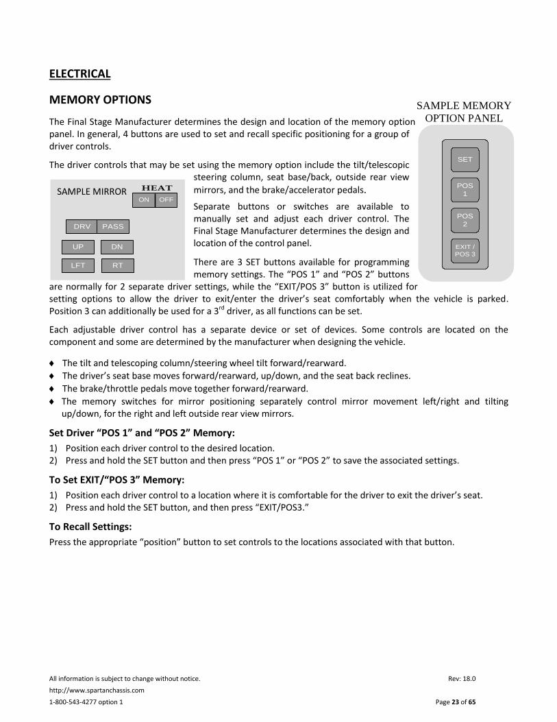
The Final Stage Manufacturer determines the design and location of the memory option panel. In general, 4 buttons are used to set and recall specific positioning for a group of driver controls.
The driver controls that may be set using the memory option include the tilt/telescopic steering column, seat base/back, outside rear view
mirrors, and the brake/accelerator pedals.
Separate buttons or switches are available to manually set and adjust each driver control. The Final Stage Manufacturer determines the design and location of the control panel.
There are 3 SET buttons available for programming memory settings. The “POS 1” and “POS 2” buttons
are normally for 2 separate driver settings, while the “EXIT/POS 3” button is utilized for setting options to allow the driver to exit/enter the driver’s seat comfortably when the vehicle is parked. Position 3 can additionally be used for a 3rd driver, as all functions can be set.
Each adjustable driver control has a separate device or set of devices. Some controls are located on the component and some are determined by the manufacturer when designing the vehicle.
The tilt and telescoping column/steering wheel tilt forward/rearward.
The driver’s seat base moves forward/rearward, up/down, and the seat back reclines.
The brake/throttle pedals move together forward/rearward.
The memory switches for mirror positioning separately control mirror movement left/right and tilting up/down, for the right and left outside rear view mirrors.
Set Driver “POS 1” and “POS 2” Memory:
1) Position each driver control to the desired location. 2) Press and hold the SET button and then press “POS 1” or “POS 2” to save the associated settings.
To Set EXIT/“POS 3” Memory:
1) Position each driver control to a location where it is comfortable for the driver to exit the driver’s seat. 2) Press and hold the SET button, and then press “EXIT/POS3.”
To Recall Settings:
Press the appropriate “position” button to set controls to the locations associated with that button.
DRV PASS
LFT
UP
RT
DN
ON OFF
HEATSAMPLE MIRROR
CONTROLS
SAMPLE MEMORY
OPTION PANEL

All information is subject to change without notice. Rev: 18.0
http://www.spartanchassis.com
1-800-543-4277 option 1 Page 24 of 65
ENGINE CONTROLS
Ignition Switch
The ignition switch turns on accessory power and starts the engine. Refer to GETTING STARTED section for additional start-up information.
To start the engine under normal starting conditions:
Turn the key to the 'ON' position and check to see that all warning lights and audible alarms are functioning. Do not depress the accelerator pedal.
Wait for the ‘WAIT TO START’ lamp to go out.
Turn the key to the ‘START' position and release when engine starts. Do not depress accelerator pedal until after the engine starts.
Refer to the engine operation manual for additional engine starting/operating instructions. Specific information may apply for particular engine models and/or if conditions other than normal exist.
Accelerator Pedal
When depressed, the accelerator pedal increases the engine speed and thus the speed of the vehicle. The pedal is located on the driver's side floor or suspended on a vertical support under the dash to the right of the brake pedal.
Certain chassis models are equipped with an adjustable pedal system. With this system, the driver may easily adjust the accelerator and brake pedal for the most comfortable position. Refer to the Final Stage Manufacturer’s literature for location and operation of the controls to operate the system.
Cruise Control and Idle Control
The Final Stage Manufacturer typically installs the operating controls for the cruise and idle functions. They may be located in the dash as switches, in the center of the steering wheel pad, or integrated into the turn signal lever on the steering column. Refer to the Steering Wheel and Column Controls section in this manual and the Final Stage Manufacturer’s literature to identify their location.
DO NOT use the cruise control function during inclement weather, adverse road conditions, or in heavy traffic.
Use Ultra - Low Sulfur Diesel Fuel Only
Usage of biodiesel or any other alternative fuel is subject to the standards and guidelines of the engine manufacturer. Before using, please contact your engine manufacturer for current information to determine if warranty is affected.

All information is subject to change without notice. Rev: 18.0
http://www.spartanchassis.com
1-800-543-4277 option 1 Page 25 of 65
The cruise functions are cancelled when the brake pedal is applied.
Cruise control functions operate as follows:
Press and Release: To:
‘ON’ Activate the cruise system.
‘OFF’ Deactivate the cruise system.
‘SET/COAST’ Set: Sets cruise speed at the speed the vehicle is traveling when applied.
Coast: Decreases the set cruise speed when control is pressed and held.
‘RES/ACCEL’ Res: Resets to the previously set cruise speed if cruise has been cancelled and still ‘on.’
Accel: Increases set cruise speed when control is pressed and held.
‘CANCEL’ Cancels cruise functions.
(steering wheel only)
Idle Control Your chassis is equipped with control systems for the high idle function. To set a high idle speed, first put the engine at idle, the transmission in neutral, and engage the park brake. Then activate the cruise system by turning it ‘ON’. DO NOT depress the accelerator or brake pedal. Version A
1. Obtain the initial high idle setting by pressing 3. Lower the engine speed by pressing and holding and releasing either the ‘SET’ or ‘RESUME’ the ‘RESUME’ control. A minimum RPM is pre-set. control.
2. Increase engine speed by pressing and holding 4. To return to the initial high idle speed, press and The ‘SET’ control. A maximum RPM is pre-set. And release the ‘RESUME’ button.
These functions may be canceled by turning the cruise system ‘OFF’, depressing the brake pedal, or pressing the ‘CANCEL’ control (steering wheel only).
For additional information about setting the idle speed, refer to the engine operation manual.

All information is subject to change without notice. Rev: 18.0
http://www.spartanchassis.com
1-800-543-4277 option 1 Page 26 of 65
STEERING WHEEL AND COLUMN CONTROLS
Hazard Warning System
The hazard warning system is a combination of four-way flashers, which are activated by pulling ‘out’ the slide switch located on the bottom side of the column. Push the slide switch ‘in’ to deactivate. Refer to FIG. 4-1.
The flashers will not flash during braking. In addition, when the hazard warning flashers are on, the turn signals will not operate.
Turn Signal Lever, High/Low Headlamp Beam, (Non-Smart Wheel Only) Cruise/Idle Control
Moving the lever clockwise activates the right turn signal. Moving the lever counterclockwise activates the left turn signal. Pulling the lever toward the driver switches the headlamps between low beam and high beam. Refer to FIG. 4-1. Refer to the Engine Controls section of this manual for operating information about the cruise and idle control functions.
Tilt Wheel and Telescopic Column Controls
The tilt wheel and telescopic functions allow positioning of the steering wheel for driver preference. Refer to FIG. 4-1.
Pull the lever while tilting the steering wheel to the preferred position. The same control operates the telescopic column by pushing on the lever while positioning the column. On units equipped with column drive, tilting the steering wheel and extending and collapsing the steering wheel is accomplished by depressing a foot pedal located near the floor on the left side of the steering column and positioning the wheel and column as desired. Be sure wheel is secured before driving.
Steering Column Controls
FIG. 4-1

All information is subject to change without notice. Rev: 18.0
http://www.spartanchassis.com
1-800-543-4277 option 1 Page 27 of 65
STEERING WHEEL CONTROLS Refer to FIG. 4-2 & 4-3.
Do not push buttons on the steering wheel while turning the ignition switch from the off to the on position. If button is pushed recycle ignition without pressing buttons.
Headlamp Flash
When the headlamps are ‘OFF’ and this button is pressed, the headlamps will turn on for as long as the button is held. The opposite occurs if the headlamps are ‘ON.’
Daytime Running Lamps
The daytime running lamps can be turned off by applying the parking brake or by turning the ignition ‘OFF.’
Marker Lamp Flash
When the marker lamps are ‘ON’ and this button is pressed, the marker lamps will turn ‘OFF’ for as long as the button is held. The opposite occurs if the marker lamps are ‘OFF.’
Cruise and Idle Control Functions
The four buttons on the lower left side are the cruise control and idle control buttons. Refer to the Engine Controls section of this manual for additional information.
Wiper Control Functions
The four buttons on the lower right side are the wiper control buttons.
Wiper High / Low
Press to activate wipers. When initially turned on, the wipers will be at low speed. Pressing the button a second time shifts the wipers to high speed. Every time the button is pressed, the wipers alternate between low and high speed.
Wiper Wash
Press to pump and squirt fluid onto the windshield. If pressed when the wipers are off, the wipers will complete approximately 3 cycles and then turn off again.
Wiper Variable Display
If the button is pressed one time, and not pressed again within 30 seconds, the wipers will ‘pulse’ – completing only one cycle. If the button is pressed a second time within 30 seconds, an ongoing delay wipe function will occur. The delayed time interval between wipe cycles will equal the time interval between when the button was pressed the first and second time. Initiation of any other wiper function will override the variable setting.

All information is subject to change without notice. Rev: 18.0
http://www.spartanchassis.com
1-800-543-4277 option 1 Page 28 of 65
Tilt (Memory Power Column)
Press down/or pull up to adjust tilt of column up or down.
Telescope Column (Memory Power Column)
Press down/or pull up to adjust column height up or down.
Pedals (Memory Power Column)
Press down/or pull up to move adjustable pedals forward or backward.
Note: For more information about radio, controls refer to the applicable supplier information in the manual.
Steering Wheel with Center Controls FIG. 4-2
Memory Power Only Memory Power Only
Steering Wheel with Radio Controls FIG. 4-3

All information is subject to change without notice. Rev: 18.0
http://www.spartanchassis.com
1-800-543-4277 option 1 Page 29 of 65
TELLTALES
A panel in the dash, with display symbols similar to those shown in FIG. 4-4, is typically supplied by Spartan and installed by the Final Stage Manufacturer as part of the completed vehicle. Each symbol position is electronically configured to illuminate and activate a buzzer when a specific condition is detected. It is important to understand the details of each warning symbol by reading the appropriate chassis system section and component manufacturer’s literature. For instance, by reviewing the section in the ‘engine’ operation manual describing electronic fault codes, the operator will have a better understanding of the specific reasons for the activation of symbol numbers 11 through 18 shown in FIG. 4-4. Not all telltale indicators shown in this section are included with every Spartan chassis. Some telltales may represent optional use equipment or supplied by the Final Stage Manufacturer.
CRITICAL SYSTEM TELLTALES
While all telltale symbols are important, some are more significant in that they are meant to alert the driver to take immediate action due to the potential failure of an important system.
1. Left Turn 10. Malfunction Indicator 2. HEST (High Exhaust System Temperature) 11. ABS Fault Indicator 3. DPF (Diesel Particulate Filter) 12. Check Engine 4. Cruise Active 13. Stop Engine 5. High Beam 14. DEF Indicator 6. Park Brake 15. Wait to Start 7. Seat Belt Warning 16. Check Transmission 8. Low Fuel 17. Transmission Over Temp 9. Right Turn 18. Range Inhibit
ADDITIONAL TELLTALES
Additional telltales such as the brake warning light or audible alarms (buzzers) are explained in each of the system specific sections where applicable. Refer to the Final Stage Manufacturer’s literature for further information or contact the Spartan Customer & Product Support Group at 1-800-543-4277.
Telltales
FIG. 4-4
1 2 3 4 5 6 7 8 9
10 11 12 13 14
1414
15 16 17 18

All information is subject to change without notice. Rev: 18.0
http://www.spartanchassis.com
1-800-543-4277 option 1 Page 30 of 65
GAUGES
The following information provides a basic description of the different types of gauges associated with chassis systems that may be supplied by Spartan. The illustrations and descriptions shown here are for general reference only. Not all gauges shown in this section are included with every Spartan chassis. Some gauges may be optional use equipment or supplied by the Final Stage Manufacturer. The gauge illustrations are standard gauges, metric gauges may be available.
AIRFLOW RESTRICTION GAUGE
The airflow restriction gauge indicates that the air filter needs servicing and can be reset after it has been serviced. The gauge measures the vacuum at the air cleaner, and is located on the engine side of the air cleaner system, as the air filter gathers dirt, the vacuum increases. Refer to the manufacturer’s literature for further details. A typical airflow restriction gauge is shown below with an example of a reset button.
AIR PRESSURE GAUGE
A vehicle with full air brakes has two air pressure gauges. Each gauge is attached to an independent air system and has a warning indicator light, which is also referred to as the brake warning light.
The primary air system, also referred to as system #1 (Rear Air), operates the service brakes on the rear axle. The secondary air system, or system #2 (Front Air), operates the brakes on the front axle.
FIG. 4-6
Bottom View Side View
FIG. 4-5

All information is subject to change without notice. Rev: 18.0
http://www.spartanchassis.com
1-800-543-4277 option 1 Page 31 of 65
The normal air operating pressure is 100 to 140 psi, which is pre-set at the factory. Before moving the vehicle, be sure both gauges are within the normal operating range. If the air system pressure cannot be maintained, and/or a malfunction occurs, the driver is alerted by the warning indicator lamps and audible alarms if present. If any warning indicator lamps and audible are active refer to applicable manufacturer’s manual, and contact an authorized service facility or Spartan Customer & Support Group at 1-800-543-4277.
The engine coolant temperature is shown with this gauge. The operating temperature is determined by engine model. Refer to engine operations manual.
FIG. 4-6a
ENGINE OIL PRESSURE GAUGE
The engine oil pressure is shown with this gauge. For normal operating range refer to engine operations manual.
FIG. 4-7
TRANSMISSION FLUID TEMPERATURE GAUGE
The transmission oil temperature is shown with this gauge. For normal operating range refer to transmission operations manual.
FIG. 4-7a
ENGINE COOLANT
TEMPERATURE GAUGE ENGINE FUEL LEVEL GAUGE
FIG. 4-6b
The level of fuel in the fuel tank is shown with this gauge. Reserve fuel capacity below empty varies by chassis model.

All information is subject to change without notice. Rev: 18.0
http://www.spartanchassis.com
1-800-543-4277 option 1 Page 32 of 65
VOLTMETER
The current voltage of the chassis electrical system is shown with this gauge. The normal operating range is 12 - 14.5 volts.
FIG. 4-7b
The engine speed is shown with this gauge and expressed in RPM (revolutions per minute).
TACHOMETER
FIG. 4-7c
DIESEL EXHAUST FLUID
The vehicle’s level of DEF in tank is shown here. Located in the bottom
of Engine Fuel Gauge.
FIG. 4-8a
SPEEDOMETER
The vehicle’s speed is shown with this gauge
FIG. 4-8

All information is subject to change without notice. Rev: 18.0
http://www.spartanchassis.com
1-800-543-4277 option 1 Page 33 of 65
DIESEL EXHAUST FLUID
The chart below explains each of the indicator levels you might see on the DEF indicator.

All information is subject to change without notice. Rev: 18.0
http://www.spartanchassis.com
1-800-543-4277 option 1 Page 34 of 65
ELECTRICAL
Do not handle electrical components after having handled diesel exhaust fluid.
Chassis Batteries
Inspect batteries for any sign of loose connections or corrosion at the terminals. Assure the battery is securely mounted. The battery manufacturer’s manual, included in this manual, contains information about the proper care of the batteries equipped on your chassis. Batteries must be maintained in accordance with the recommendations on the battery manufacturer’s manual to ensure full battery life. Your vehicle may be equipped with an onboard battery charger for the purpose of maintaining the battery’s charge level during periods of inactivity. If your chassis is not equipped with such a battery charger, you must provide a means of keeping the batteries properly charged during periods of inactivity.
Fuse Panels/Boxes
Refer to FIG. 4-9. A fuse box contains fuses for the electrical circuits of your vehicle. As manufactured, fuse boxes are attached to Power Distribution Center (PDC) panels. Generally, there are front and rear PDCs that are permanently installed by the Final Stage Manufacturer. Refer to the Final Stage Manufacturer’s literature for specific location(s) of the PDC panels.
Visually inspect the front and rear fuse boxes for blown fuses or corrosion. Never replace a ‘blown’ fuse with a higher rated amperage fuse; use a fuse with the same rating. Should replacement fuses repeatedly malfunction, take your vehicle to the nearest authorized service facility, contact Spartan Customer & Product Support Group at 1-800-543-4277, or the appropriate Final Stage Manufacturer customer service department.
TOP VIEW TYPICAL REAR FUSE BOX
FIG. 4-9
TOP VIEW TYPICAL FRONT FUSE BOX

All information is subject to change without notice. Rev: 18.0
http://www.spartanchassis.com
1-800-543-4277 option 1 Page 35 of 65
Powertrain/Chassis Fuse Locations
A typical chassis will have a Chassis Service Center located at the right rear of the vehicle which will contain the
rear Power Distribution Center (PDC), a chassis electrical disconnect switch, and a single Mega® fuse. Your chassis may also contain an optional second disconnect switch as shown in FIG. 4-10.
The single Mega® fuse (typically 125A) provides direct battery power to the rear PDC (J1 stud). The upper disconnect switch has built-in circuit protection rated at 150A and provides battery power to the rear PDC (J3 stud), Front PDC, and the SCM. Activating this disconnect switch removes battery power from the listed items. Note: this switch will inhibit the coach from starting and/or running if the internal circuit breaker has tripped or the switch has been manually switched off.
The rear PDC provides fuses and relays for items such as, but not limited to, the Engine Control Module (ECM), TCM, and Anti-lock Brake System (ABS).
The optional lower disconnect switch is installed for the final stage manufacturer use. Consult the final stage manufacturer for detailed information.
MAXI FUSE REAR PDC
FIG. 4-10
CIRCUIT BREAKERS

All information is subject to change without notice. Rev: 18.0
http://www.spartanchassis.com
1-800-543-4277 option 1 Page 36 of 65
On Board Diagnostic (OBD) (If Equipped)
The following components or systems due to OBD/emissions system certification shall not be modified.
Vehicle speed sensor
Coolant level sensor
Ambient air temperature sensor
Vehicle accelerator pedal
Malfunction Indicator Lamp (MIL)
9-pin diagnostic Interface connector
OBD designated connector by black cap marked, “OBD,” or an uncapped 9-pin diagnostic connector.
OR
Any component/system of the aftertreatment.
Owners/Operators:
SHALL NOT install object(s) that will result in abnormal temperature to occur on the emissions control system.
SHALL NOT restrict access to fill tube or label for the DEF tank.
SHALL NOT install anything that will cause the designated OBD, 9-pin Diagnostic Interface, connector to be covered or obstructed.
SHALL maintain proper clearance of their add-on devices to the high temperature components of the emissions control systems. Refer to applicable section in engine manufacturer’s manual.
SHALL take unit to an authorized service center once incorrect Diesel Exhaust Fluid has been detected.
Malfunction Indicator Lamp (MIL) (If Equipped)
The MIL may illuminate when the ECM detects any failure that could affect tail pipe emissions. Certain failures, which may occur, could result in the illumination of the MIL, contact an authorized service facility or Spartan Customer Product and Support at 1-800-543-4277.
For additional information, please refer to applicable manufacturer’s manual.
On-Board Weighing System (OBWS) (If Equipped)
Not all components described in this section are included with every chassis. Some components may be optional equipment. For supplemental operating information relevant to the completed vehicle, refer to the Final Stage Manufacturer’s literature and the respective component manufacturer’s literature.
The On-Board Weighting System (OBWS) shall be used for reference only. For actual vehicle weights, the vehicle must be weighed on certified scales.

All information is subject to change without notice. Rev: 18.0
http://www.spartanchassis.com
1-800-543-4277 option 1 Page 37 of 65
Weighing
Note: The vehicle must be in neutral in order for the OBWS display to be visible. If equipped with a leveling jack system, the leveling jack system must be in the stowed position for normal operation.
The following steps shall be used to weigh the vehicle using the OBWS:
Park on a level surface
Ensure the transmission is in neutral
Chock the wheels
Release the park brake
Dump air in vehicle suspension for 5-10 seconds
Re-inflate air suspension to ride height*
Weight is displayed when numbers stop blinking
Set the park brake
Remove the chocks
Resume normal operations
*See Chassis Ride Height Specifications.
Calibration
Spartan recommends recalibrating the OBWS once per every year or after any time the suspension components have changed.
For additional information please, refer to the applicable OBWS manufacturer’s calibration and operations manual.

All information is subject to change without notice. Rev: 18.0
http://www.spartanchassis.com
1-800-543-4277 option 1 Page 38 of 65
5.0 ENGINE

All information is subject to change without notice. Rev: 18.0
http://www.spartanchassis.com
1-800-543-4277 option 1 Page 39 of 65
ENGINE
The power train of this vehicle is equipped with certain components that may be warrantable against defects or mis-builds for a period of five years, 100,000 miles, or 3,000 engine hours, whichever occurs first. If a defect or mis-build is identified in components in the power train, contact Spartan Customer & Product Support Group at 800-543-4277.
Problems with any of the following can result in engine damage, overheating, and/or reduced engine performance.
Air Intake Tubing Inspect for wear points, loose connections, tubing damage, or punctures that could cause leaks.
Airflow Restriction Gauge Check the airflow restriction by the reading on the gauge. Change the air filter element as necessary and reset gauge. A sample gauge is shown in Section 4.
Coolant Hoses, Pipes/Tubes, Clamps Inspect for wear points, loose connections, leaks, damage, or punctures.
Radiator/Charge Air Cooler Inspect for wear points, loose connections, tubing damage, or punctures that could cause leaks.
Engine Cooling Fan Check for nicks, cracks, loose or bent blades, loose rivets, or any other type of damage.
Do not attempt to repair or continue use of a damaged fan blade. This could cause component failure, personal injury and/or property damage.
Engine Coolant Level Coolant level in the reservoir should be at or above the sight glass when the engine is cold. Refer to FIG. 5-1. Use the fluid specified on the component label. Never mix different types of coolant.
Never remove radiator cap or surge tank cap while coolant is hot. Remove cap slowly when coolant is at ambient temperature. A sudden release of pressure from a heated cooling system can result in serious personal injury from burst of hot coolant. Do not add cold coolant to a hot engine as serious damage to the engine could occur.
TYPICAL COOLANT RESERVOIR FIG. 5-1

All information is subject to change without notice. Rev: 18.0
http://www.spartanchassis.com
1-800-543-4277 option 1 Page 40 of 65
Coolant Maintenance Regularly maintained coolant and filters are critical to the performance and durability of the engine. Refer to the engine manufacturer’s documentation for intervals required to check/maintain the coolant level, intervals to flush coolant, change filters, and procedures to service the coolant systems. If the coolant sensor is to be removed for maintenance purposes, the sensor shall be reinstalled as follows: Hand tighten, and use a hex area of sensor and torque to 26 in. lbs. (+/- 1 in-lbs.), then torque clock the sensor 1/2 to 3/4 of a turn so that the 3-pin connector is in the vertical position. After refilling the reservoir verify there are no leak paths.
Failure to maintain appropriate engine coolant mixture could result in emissions critical component failure.
Fuel/Water Separator If water is present, open drain valve until fluid drains from the drain tube; drain filter sump until clear fuel is visible. Drain fluid into a container and not on the ground. For additional information, refer to the engine operation manual.
Drained fluid may contain toxic material; dispose of in compliance with local environmental regulations.
Engine Drive and Accessory Belts Check for adequate belt tension and unusual belt wear or shiny spots. In the absence of a gauge to check belt tension, apply a firm force to the belt (approximately 30 lbs. of pressure) halfway between the 2 pulleys. The belt should press in no more than 1/2”.
Lubricating Oil Check and correct oil level if necessary. The vehicle should be level with the engine off. Pull dipstick from the dipstick tube, wipe oil off dipstick, and reinsert into dipstick tube. Ensure dipstick is fully seated before removing to check oil level on dipstick. Fill if necessary.
Refer to the engine operation manual for oil fill instructions. If the primary engine oil fill location cannot be accessed as described in the manual, an auxiliary fill tube is installed for ease of serviceability and is identified as such. Refer to FIG. 5-2.
AUXILIARY OIL FILL TUBE SHOWN MOUNTED TO THE FUEL PUMP SIDE OF THE ENGINE
FIG. 5-2

All information is subject to change without notice. Rev: 18.0
http://www.spartanchassis.com
1-800-543-4277 option 1 Page 41 of 65
MECHANICAL FAN DRIVE GEAR BOX
The gearbox is located behind the fan assembly. Refer to Maintenance Schedule at the end of this manual for information about the maintenance intervals. For V-Belt tensioning information and the recommended tool to help maintain the correct V-Belt tension.
FAN BELT TENSIONING GUIDELINES FOR K3 CHASSIS (ONLY) Maska P/N 006347
To order, contact Spartan Aftermarket Parts Department
Toll Free 1-800-722-3025
Email: [email protected]
Decal for V-Belt Tensioning Instructions FIG. 5-3
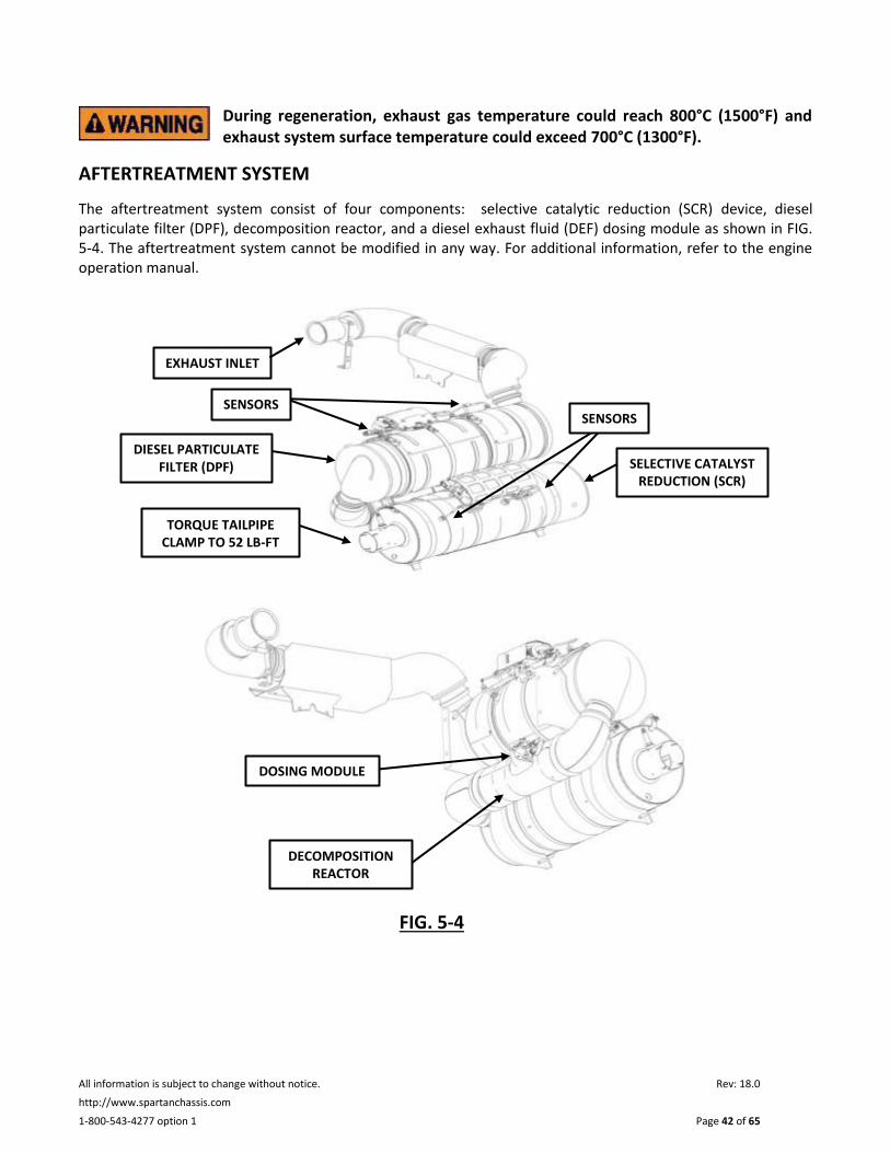
All information is subject to change without notice. Rev: 18.0
http://www.spartanchassis.com
1-800-543-4277 option 1 Page 42 of 65
During regeneration, exhaust gas temperature could reach 800°C (1500°F) and exhaust system surface temperature could exceed 700°C (1300°F).
AFTERTREATMENT SYSTEM
The aftertreatment system consist of four components: selective catalytic reduction (SCR) device, diesel particulate filter (DPF), decomposition reactor, and a diesel exhaust fluid (DEF) dosing module as shown in FIG. 5-4. The aftertreatment system cannot be modified in any way. For additional information, refer to the engine operation manual.
FIG. 5-4
FIG.
DECOMPOSITION REACTOR
DOSING MODULE
SELECTIVE CATALYST REDUCTION (SCR)
EXHAUST INLET
DIESEL PARTICULATE FILTER (DPF)
TORQUE TAILPIPE CLAMP TO 52 LB-FT
SENSORS SENSORS

All information is subject to change without notice. Rev: 18.0
http://www.spartanchassis.com
1-800-543-4277 option 1 Page 43 of 65
Diesel Exhaust Fluid (DEF), a key element in the SCR process, is a solution of purified water and 32.5% automotive-grade urea. When combined with the heat of the exhaust stream and the SCR device, DEF helps convert NOx into harmless nitrogen and water vapor. DEF is non-toxic and non-flammable and it will not harm people, animals, equipment, or the environment when handled properly. Shown in FIG. 5-5 is the DEF tank.
Do not remove primary DEF fill cap while filling DEF tank from remote fill side. This could result in overfilling of DEF tank and spilling DEF.
Do not overfill DEF tank.
FIG. 5-5

All information is subject to change without notice. Rev: 18.0
http://www.spartanchassis.com
1-800-543-4277 option 1 Page 44 of 65
6.0 TRANSMISSION

All information is subject to change without notice. Rev: 18.0
http://www.spartanchassis.com
1-800-543-4277 option 1 Page 45 of 65
TRANSMISSION
Fluid Level Inspect and correct transmission fluid level at cold fill line. Refer to the transmission operation manual for more detailed information and fluid specifications.
TRANSMISSION SHIFT SELECTOR
The transmission shift selector is permanently installed by the Final Stage Manufacturer. It is either a ‘pushbutton’ or a ‘lever’ style. The drive “D” and reverse “R” positions should be used for normal driving. The neutral “N” position should be used when the vehicle is stationary or parked (with the park brake engaged).
Refer to the transmission operation manual for detailed explanations of each function and operating procedures. The transmission manual describes the selector positions, operating ranges, temperatures, and offers driving tips.

All information is subject to change without notice. Rev: 18.0
http://www.spartanchassis.com
1-800-543-4277 option 1 Page 46 of 65
7.0 AXLES/WHEELS & TIRES

All information is subject to change without notice. Rev: 18.0
http://www.spartanchassis.com
1-800-543-4277 option 1 Page 47 of 65
TIRES AND WHEELS
Exceeding the tire speed rating, an overloaded wheel position, and/or an improperly inflated tire could cause component failure or loss of vehicle control, resulting in serious injury, death, and property damage.
Air Pressure Check and correct, if necessary, the air pressure in each tire according to the actual vehicle weight and the guidelines provided by the tire manufacturer.
For the most current tire inflation information refer to the respective manufacturer’s website for downloadable inflation tables.
Goodyear Website: http://www.goodyear.com/rv/ Michelin Website: http://www.michelinrvtires.com/michelinrv/index.jsp
For your safety, and to optimize the ride quality, handling, and tire wear of your motorhome, we strongly recommend weighing individual wheel positions of your motorhome in your fully loaded condition, and setting tire pressures based on those weights. The best source for the correct pressures is the tire manufacturer’s website listed above.
If you do not know the axle weights of your motorhome, tires should be inflated to the pressures shown on your chassis data tag, which is typically located in the driver’s compartment. It is also located on the vehicle certification label provided by the Final Stage Manufacturer. Refer to the Final Stage Manufacturer’s literature for certification label location.
Tire pressures must be monitored closely to assure safe operation of the vehicle. Spartan recommends checking tire pressure daily when the vehicle is being driven.
It is important to understand that a change in weight distribution or the amount of weight added or removed from the vehicle may require a change to tire pressures. Refer to the Gross Axle Weight section of this manual and the appropriate website address stated above.
ROLLING RESISTANCE
Rolling resistance of the tires is critical to greenhouse gas emissions and fuel economy of the vehicle. This vehicle was originally built with tires that are appropriately rated for the weight capacity they may be expected to carry. When replacing tires, it is critical to consider tires with similar tread patterns and the same load capacity as those of which the vehicle was originally equipped. Should you have questions regarding replacement tires, please contact Spartan or your nearest tire distributor.
TIRE PRESSURE MONITORING SYSTEM
Your Spartan may be equipped with an active tire pressure and temperature monitoring system. At the push of a button, the system provides the driver with real-time tire pressure and temperature data – even when the vehicle is in motion. This system is for monitoring purposes only and should never replace your tire manufactures inflation ratings. For additional information on features and operation of the control, please refer to the Final Stage Manufacturer’s Operations and Maintenance Manual.
Condition Check the condition of the tires daily. Look for any bumps, blisters, cuts, punctures, cracks, uneven wear, check for proper inflation, and tread depth. Replace tire on front axle when tread is worn to 4/32 in. (3.175 mm).

All information is subject to change without notice. Rev: 18.0
http://www.spartanchassis.com
1-800-543-4277 option 1 Page 48 of 65
Replace tire on rear axle when tread is worn to 2/32 in. (1.5888 mm). Always check inflation pressure when tires are cold. If there are signs of abnormal tire wear, take vehicle to an authorized service center to have the axles and steering system inspected for worn or damaged components and proper alignment.
Wheel Nuts Remove lug covers and check that all wheel nuts are in place and secured. Refer to the wheel manufacturer’s information is located after Section 9 of this manual or visit a certified service facility to ensure wheel nut torque
is checked/maintained within the recommended guidelines based on mileage and time factors.
Re-tightening should occur only after the 50-150 miles are covered in normal driving conditions. This practice ensures that the opportunity for over-tightening is minimized. There is little benefit from re-tightening wheel nuts prior to reaching this service threshold, since joint relaxation may only be partial. If audits of initial installation torque are desired, they should be performed as shortly after the initial tightening as possible and should determine the breakaway torque values (the amount of torque required to just begin movement of the nut in the tightening direction.)
The use of manual torque wrenches must be carefully monitored. Dial type torque wrenches are preferred. Click-style wrenches may not be as accurate as dial-type and could be affected by hand position. Regardless of type of wrench used care must be exercised so that 450-500 ft.-lbs. torque is actually applied.
Re-tightening of wheel nuts should be accomplished “cold” and not with excessively hot brakes. A good rule of thumb for checking this is to re-tighten only after the wheel disc and nuts are cool enough for continuous skin contact only.
TIRE SPEED RATING
Vehicle should not be operated at speeds above the lowest tire speed rating on the vehicle. Refer to the tire manufacturer’s information to determine the specific speed rating for your tires.
AXLES
Hub Covers Removal of hub covers is necessary to verify wheel bearing oil levels in the front (steer) axle and tag axle. To remove the hub cover, remove the hub cover knob in the center of the hub cover by rotating it counter clockwise using the installation/removal tool (RW2GNT) Refer to FIG. 7-1 located with the owner’s manual. Once knob is removed slide cover off of mounting bracket.
To reinstall hub cover slip it over the mounting bracket making sure that tangs on the bracket engage holes in cover. Install hub cover knob stud through center hole in hub cover and rotate clockwise until first indent is felt. Using installation/removal tool, turn knob an additional 5-6 indents. Refer to FIG. 7-1a.

All information is subject to change without notice. Rev: 18.0
http://www.spartanchassis.com
1-800-543-4277 option 1 Page 49 of 65
Front Axle Check for leaks. Check and correct, if necessary, the fluid level to the manufacturer’s specification using the proper fluid recommended by the axle manufacturer. The axle manufacturer’s maintenance information is located in the back of this manual. Check that U-bolts are secure and there are no visible signs of looseness or
movement.
Rear Axle Check for leaks. Check and correct, if necessary, lube level to the manufacturer’s specifications using the proper lube recommended by the axle manufacturer. The axle manufacturer’s maintenance information is located in the back of this manual. Check that U-bolts are secure and there are no visible signs of looseness or movement.
VEHICLE WEIGHT
Vehicle Weight Worksheet A Vehicle Weight Worksheet on page 50 should be completed at full traveling weight. Heavy items should be distributed evenly side-to-side and as low as possible in the vehicle. It is important that the loaded weight of each wheel position be known to ensure that the GAWR and GVWR are not exceeded. Refer to Section 2 of this manual.
FIG. 7-1
FIG. 7-1a

WORKSHEET - VEHICLE WEIGHT
All information is subject to change without notice. Rev: 18.0
http://www.spartanchassis.com
1-800-543-4277 option 1 Page 50 of 65
All information is subject to change without notice. Rev: 18.0
http://www.spartanchassis.com
1-800-543-4277 option 1 Page 51 of 65
8.0 STEERING, BRAKES, AND SUSPENSION

All information is subject to change without notice. Rev: 18.0
http://www.spartanchassis.com
1-800-543-4277 option 1 Page 52 of 65
CHASSIS SYSTEMS
Not all controls described in this section are included with every chassis. Some controls may be optional equipment. For supplemental operating information relevant to the completed vehicle, refer to the Final Stage Manufacturer’s literature and the respective component manufacturer’s literature.
Understanding the function of the operator controls is critical to safe driving. Systems and components must be inspected and maintained as recommended by the manufacturers. Refer to the pre-trip and maintenance sections for further information.
AIR SUSPENSION DUMP SYSTEMS
Chassis Suspension Dump Systems (optional)
There are two types of chassis suspension dump systems:
1. If a leveling jack system is present, a suspension dump system specific to the jack system is operated by a set of leveling jack controls. The leveling jack system and controls are installed by the Final Stage Manufacturer and located in the dash area.
As designed, the leveling jack system cannot be operated unless the park brake is set. If you find that the leveling jack system is operational without the park brake being set, contact Spartan Customer & Product Support immediately and take your vehicle to the nearest authorized service center.
Refer to the Final Stage Manufacturer’s operational manual and the leveling jack manual to understand the procedures and controls for the leveling jack system.
2. A full chassis dump system is available that may also include a leveling jack dump system. The chassis dump system is manually activated by pressing and holding the momentary switch in the dash area which is installed by the Final Stage Manufacturer. Re-inflation to adjusted ride height begins when switch is released. Refer to the Final Stage Manufacturer’s operation manual for specific location and description of controls.
There is a lockout feature to prevent activation at or above 8 mph for the air suspension. Once the lock-out feature is enabled, the full chassis dump system cannot be activated until vehicle speed reaches 5 mph or less.
Tag Axle Suspension Dump System A Spartan chassis designed with a tag axle suspension dump system is capable of providing better traction than a chassis without a tag axle suspension dump system. When air is depleted from the tag axle suspension, more weight is distributed to the drive axle, thus increasing the traction capability. The dump system is controlled manually (optional).
Manual Control Manual operation of the tag axle dump system is optional. When present, the control is a momentary switch that is installed by the Final Stage Manufacturer in the dash area. Refer to the Final Stage Manufacturer’s operation manual for specific location and description.
The tag axle suspension dump system is activated by pressing and holding the switch. There is a lockout feature to prevent activation at or above 8 mph. Once the lock-out feature is enabled, the dump system cannot be activated until vehicle speed is 5 mph or less. Re-inflation to adjusted ride height begins when switch is released.

All information is subject to change without notice. Rev: 18.0
http://www.spartanchassis.com
1-800-543-4277 option 1 Page 53 of 65
Automatic Control The tag axle suspension dump system is activated automatically when the vehicle’s transmission is placed in reverse and begins re-inflation to adjusted ride height when the transmission is taken out of reverse. Not all final stage manufactures offer this option.
Hadley® SAMS/Smart Air Management System Certain Spartan chassis are equipped with Hadley® Smart Air Management System. This electronically based system is designed to maintain normal vehicle ride height control automatically and provide a means for manually lower or raise the ride height through a customized interface. Refer to the Manufacturer’s literature for operation of the controls to operate the system.
Hadley® SLS/ Self Leveling System Certain Spartan chassis are equipped with Hadley® Smart Air Management System and include the self-leveling feature. This electronically based system is designed for this application to maintain a predetermined vehicle ride height automatically and provide a means to manually lower or raise the ride height through a customized interface. Many of the user settings are available only when operating below certain speeds or when the parking brake is applied. Refer to the Manufacturer’s literature for operation of the controls to operate the system.
BRAKE SYSTEM AND CONTROLS
The brake system of the vehicle is designed to function safely and predictably over a wide range of road and driving conditions.
Service Brakes Service brakes are applied when the brake pedal (also referred to as the treadle) is depressed. The brake pedal is located on the driver’s side floor, to the left of the accelerator pedal or suspended on a vertical support under the dash.
ABS Every chassis is equipped with ABS (Anti-lock Braking System), which is a system designed to improve driver control and vehicle stability during braking by helping to prevent wheel lock-up. DO NOT rapidly 'pump' the brakes (press and release the brake pedal) during brake application or the ABS will not respond as designed.
The ABS functions are monitored separately from the service brake functions. If the ABS warning light stays illuminated, this is an indication that there is a malfunction with the ABS. The vehicle may have lost all or part of the anti-lock functions. This does not mean that the vehicle is without braking capability. The service brakes will function independent of the ABS, but operating the vehicle without ABS may affect the operator’s ability to control the vehicle during braking on slippery surfaces or during emergency stops. If this occurs, the vehicle should be taken to a service center as soon as possible.
Automatic Traction Control (ATC) Some vehicles may be equipped with ATC, which helps with acceleration on slippery surfaces and reduces drive wheel over-spin. For further instructions refer to the ABS driver tips pamphlet located in the component manufacture’s literature.
Full Air Brake System The full air brake system consists of two independent air systems. The primary system (system #1) operates the service brakes on the rear axle while the secondary system (system #2) operates the service brakes on the front axle. An air pressure gauge and a warning light monitor each air system independently.

All information is subject to change without notice. Rev: 18.0
http://www.spartanchassis.com
1-800-543-4277 option 1 Page 54 of 65
If there is a malfunction in either system, the other system is not affected. If the primary air pressure falls below approximately 35 psi. the parking (or emergency) brakes are activated automatically. If the air brake warning indicators are activated, the vehicle must be brought to a safe stop and the brake system serviced before resuming operation.
Parking Brakes (Spring Brakes) The parking brake control is used to activate/deactivate the application of the parking brakes. When applied, an indicator light on the dash illuminates. For air brake systems, the control is a yellow, diamond-shaped, push/pull knob typically located on the dash. Refer to FIG. 8-1.
The knob automatically pops out when the air system pressure descends to approximately 35 psi. In addition, the system will not allow the parking brakes to be released unless air system pressure is approximately 60 psi.
DO NOT use auxiliary brakes in inclement weather, when driving surface is slippery, or in heavy traffic.
Some chassis models are equipped with an auxiliary brake device such as an exhaust brake or engine brake that is designed to supplement the service brakes during downhill travel when braking is required to slow the vehicle. An auxiliary brake may decrease the demand on the service brakes, but should never be used as the primary means of stopping the vehicle. Under certain conditions with slippery road surfaces, auxiliary brakes should be turned off to assure there is no loss of vehicle control. If the auxiliary brake is used it automatically activates your trailer brake lights. Refer to the manufacturer’s literature for detailed information relative to operator controls, functions, and applications.
BRAKES
Parking Brake Operation Refer to section above a description of the park brake control mechanism. Park vehicle, engage parking brake, and slowly accelerate in a low gear to check that the parking brake holds.
Service Brake Operation Depress the service brake pedal, and then release the parking brake mechanism. Be sure all warning indicators and lamps are off. Accelerate forward at a slow speed in a clear, unobstructed area, and then depress the brake pedal until the vehicle comes to a stop. Check for any ‘pull’ to one side, delay in ability to stop, or any unusual feel or noises.
PUSH/PULL KNOB Pull knob out to apply parking brake; push in to release parking brake.
FIG. 8-1

All information is subject to change without notice. Rev: 18.0
http://www.spartanchassis.com
1-800-543-4277 option 1 Page 55 of 65
COMPRESSED AIR SYSTEM
Always ensure the air pressure is removed from the air system before disconnecting any component. Pressurized air can cause severe personal injury.
Air System/Air Dryer Operation Start the vehicle and allow engine to idle. The air dryer purges when the air system is fully charged and air is exhausted from the air dryer. Generally, this can be heard as a brief release of air, at the rear of the vehicle. The air dryer manufacturer’s maintenance information is located in the back of this manual.
For your convenience, the air system may be inflated through a Schrader valve available on most chassis models either at the air dryer or the air governor.
Moisture Ejectors and Air Tank Petcocks Manual moisture ejectors and air tank petcocks should be drained daily. Automatic moisture ejectors should be checked for proper operation during routine maintenance using the manual drain mechanism as shown in FIG. 8-2.
Lanyards are color coded to identify each one with a specific system/tank:
Silver/Clear - Wet Tank
Red - Front (secondary) brake system
Green – Rear (primary) brake system
FIG. 8-2
Manual Drain Mechanism
MANUAL DRAIN VALVES WITH LANYARD EXTENSION
AUTOMATIC MOISTURE EJECTORS WITH MANUAL

All information is subject to change without notice. Rev: 18.0
http://www.spartanchassis.com
1-800-543-4277 option 1 Page 56 of 65
STEERING
Hydraulic System Refer to FIG. 8-3. Check, and correct if necessary, the level of hydraulic fluid in the hydraulic reservoir indicated with the dipstick. Always use the appropriate fluid as indicated on the reservoir label. Check for leaks or wearing of hoses.
Steering Gear / Linkage Check for any loose, cracked, or damaged steering components (e.g. linkage). Be sure to inspect for loose steering gear mounting bolts, draglink nuts, or pitman arm pinch bolt. Refer to FIG. 8-3a.
Note: The steering gear may be positioned differently than shown.
SUSPENSION
Rear Air Front and Springs / Ride Height Inspect for unusual wear or damage. Check air springs for proper inflation and that the vehicle is not leaning to either side. Check ride heights. Refer to the maintenance guide found at the end of this section. Contact Spartan for “SP” model chassis.
Shocks Inspect for unusual wear, damage, or leaks.
HYDRAULIC FLUID RESERVOIR FIG. 8-3
FIG. 8-3a STEERING GEAR INSTALLED STEERING GEAR SIDE VIEW
DRAG LINK
STEERING GEAR MOUNTING BOLT
STEERING GEAR
PITMAN ARM

All information is subject to change without notice. Rev: 18.0
http://www.spartanchassis.com
1-800-543-4277 option 1 Page 57 of 65
CHASSIS MAINTENANCE
Regular maintenance will avoid problems and prolong the life of the chassis. The information presented in the Chassis Maintenance Guide at the end of this section is not meant to override component manufacturer recommendations. Applying the information in these manuals and literature for each chassis system will ensure your chassis is maintained properly.
Maintenance interval requirements vary between applications and by system. The intervals depend heavily upon usage, driving techniques, operating environment, and frequency of operation. To fully understand the maintenance requirements for your chassis, you should be familiar with the component manufacturer’s maintenance information.
CHASSIS MAINTENANCE GUIDE / RECORDKEEPING
Extra copies of blank worksheets have been included for your convenience. We encourage you to make additional copies as needed.
Page 50 is a Vehicle Weight Worksheet provided to record important weight data.
Page 60 is a Chassis Service and Maintenance Record provided to document the history of all maintenance information for the vehicle.
Page 61-63 is a Chassis Maintenance Guide.
Professional technicians at an authorized service facility should perform scheduled chassis maintenance, inspections/corrections, and service repairs. To locate an authorized service facility, contact Spartan Customer & Product Support Group at 1-800-543-4277 Option #1.

All information is subject to change without notice. Rev: 18.0
http://www.spartanchassis.com
1-800-543-4277 option 1 Page 58 of 65
APPENDIX A MAINTENANCE, CHECKLIST, AND
SCHEDULE

All information is subject to change without notice. Rev: 18.0
http://www.spartanchassis.com
1-800-543-4277 option 1 Page 59 of 65

All information is subject to change without notice. Rev: 18.0
http://www.spartanchassis.com
1-800-543-4277 option 1 Page 60 of 65
PRE-TRIP INSPECTION ITEMS
AREA COMPONENT INSPECTION
FRONT AXLE WHEEL BEARINGS check oil level
TAG AXLE WHEEL BEARINGS check oil level
REAR AXLE check for leaks
PARK BRAKE check operation
SERVICE BRAKES check operation
AIR TANKS WITH MANUAL EJECTORS remove moisture
AIR TANKS WITH AUTOMATIC EJECTORS check operation
AIR DRYER OPERATION check operation
BATTERIES/BATTERY CABLES check for corrosion, loose connections
VISUAL INSPECTION OF FUSE PANELS check for corrosion, blown fuses
AIR INTAKE PIPING/TUBING check for loose, punctured or worn pieces
AIR CLEANER AIRFLOW RESTRICTION GAUGE restriction indicator reading
ENGINE COOLING FAN check for nicks, cracks, loose pieces
MECHANICAL FAN DRIVE GEAR BOX check for leaks
ENGINE OIL check fluid level
ENGINE COOLANT LEVEL check coolant level
ENGINE DRIVE AND ACCESSORY BELTS check for wear
DIESEL EXHAUST FLUID (DEF) LEVEL check fluid level (if stored refer to chassis storage and periods of non-use section for further information).
FUEL/WATER SEPARATOR drain checking for presence of water
RADIATOR AND CHARGE AIR COOLER presence of debris/damage
COOLANT HOSES, PIPES, AND CLAMPS check for leaks, loose clamps, chafing
CHECK EXHAUST PIPING & MUFFLER check that all components are secure
CRANKCASE BREATHER TUBE check for blockage
HYDRAULIC STEERING SYSTEM check for leaks
HYDRAULIC RESERVOIR check fluid level
STEERING WHEEL check for excessive play
FRONT AIR SPRINGS check wear and/or leaks
REAR AIR SPRINGS check wear and/or leaks
FRONT SHOCKS inspect for leaks and that all components are secure
REAR SHOCKS inspect for leaks and that all components are secure
RIDE HEIGHT check level
TRANSMISSION FLUID check fluid level
TIRES check for wear and damage, check and adjust air pressure (refer to tire manufacturer’s manual for recommended air pressure settings)
WHEELS* wheel nuts/torque to 450-500 lbs. ft.
*Lug nuts – tighten after first 50 miles & 50 miles after each time a wheel is serviced.

All information is subject to change without notice. Rev: 18.0
http://www.spartanchassis.com
1-800-543-4277 option 1 Page 61 of 65
Coolant Intervals 12 months 24 months 36 months 48 months 60 months 72 months٭
Extended Life Coolant check check add extender check check replace
Extended Life Coolant (ELC): check coolant quality by taking a sample from the surge tank and visually inspecting for any deposits. If color is close to the original color and no deposits are found, coolant is suitable to be run to the next maintenance interval. If coolant quality checks OK, check freeze point and adjust as necessary. Refer to chart above*.
Recommended Scheduled Maintenance Regular maintenance will avoid problems and prolong the life of the chassis. The information presented here is not meant to override component manufacturer recommendations; rather it is supplied to enhance the ownership experience by grouping certain maintenance items as a convenience to the owner. Please be sure to read all maintenance information available for the chassis components. If any information is unclear or you have questions or concerns, please contact the Spartan Customer & Product Support Group at 1-800-543-4277.
Service to Perform
Intervals Every 3 Months or
5,000 Miles Every 12 Months or 15,000 Miles
Every 24 Months or 30,000 Miles
Check all Belts and Tensioners - Retention Belts if Necessary initially at 3 months or 5,000 miles whichever comes first. •After initial check repeat every 12 months or 15,000 miles whichever comes first.
Check all Hoses and Clamps Including CAC System - initially at 3 months or 5,000 miles whichever comes first. •After initial check repeat every 12 months or 15,000 miles whichever comes first.
Drain Gear Box for Engine Cooling Fan removing as much of the old fluid as possible. Clean magnetic pipe plug in the bottom of the reducer at each oil change. Refill with 24 oz. of SHC 75W90 Synthetic Oil.
X
Lubricate Drive Shaft - grease - NLGI #2 or Equiv. when motorhome is in use. Note: If motorhome is stored, lube driveshaft annually. X
Lubricate Engine Cooling Fan Drive Shaft (K2 & K3 units with mechanically driven engine cooling fan) - Grease - NLGI #2 or Equiv. when motorhome is in use. Note: If motorhome is stored, lube driveshaft annually. X
Replace Spin-On (external) Hydraulic Filter Element and Refill Reservoir (units with hydrostatically drive engine cooling fan) - Reference Reservoir Label and Filter Numbers
X
Check Engine Coolant٭ - Test/adjust as Necessary. Refer to Chart Below X
Clean Radiator and CAC from Debris X
Clean Chassis Batteries and Connections X
Check and Adjust Front and Rear Suspension Ride Height; Perform Overall Inspection Reference Suspension Manufacturer's Manual.
X
Lubricate Steering Linkages and Shaft - Grease - NLGI #2 or Equiv. X
Lubricate Brake Camshafts and Slack Adjusters (if equipped) - Grease - NLGI #2 or Equiv.
X
Replace Fuel Filter (Secondary-pressure side) Cummins® Reference Engine Manufacturer's Manual
X
Replace Air Dryer Filter X
Drain Hydraulic Reservoir, Replace the Internal Filter Element, and Refill Reservoir Reference Reservoir Label and Filter Numbers (Units With Hydrostatically Drive Engine Cooling Fan)
X
Drain Power Steering Reservoir, Replace the Internal Filter Element, and Refill Reservoir - Reference Reservoir Label and Filter Numbers (Units Without Hydrostatically Drive Engine Cooling Fan)
X
Calibrate On-Board Weighing System (OBWS) (If Equipped). Refer to manufacturer’s calibration and operations manual.
X
Air filter element MUST be replaced when the restrictor indicator shows restriction, or annually, whichever occurs first.
For More Comprehensive Engine Maintenance and Intervals, Go to the Engine Section of Manual and Reference the Maintenance & Operations Sheet and Engine Manual. NOTE: The Maintenance & Operations Sheet takes Precedence over the Manufacturer's Manual
For More Comprehensive Transmission Maintenance and Intervals, Refer to the Applicable Manual in the Manual Binder
For More Comprehensive Axle Maintenance and Intervals, Refer to the Applicable Manual in the Manual Binder
For More Comprehensive Suspension Maintenance and Intervals, Refer to the Applicable Manual in the Manual Binder

All information is subject to change without notice. Rev: 18.0
http://www.spartanchassis.com
1-800-543-4277 option 1 Page 62 of 65
CHASSIS RIDE HEIGHT SPECIFICATIONS
The unit must be parked on a level surface.
K3 SERIES CHASSIS
INDEPENDENT FRONT SUSPENSION (IFS):
Model 1700: 9.25” Measuring the height of the air spring. Model IFS: 9.25” Measuring the height of the air spring. 2000 REAR SUSPENSION:
246 8.25” Measuring from bottom of chassis frame rail to center of axle housing. RD2300 20.00” Measuring the distance between the shock centers of the shock mount.
K2 SERIES CHASSIS INDEPENDENT FRONT SUSPENSION (IFS):
Model 1700: 9.25” Measuring the height of the air spring. REAR SUSPENSION:
240AR 8.25” Measuring from bottom of chassis frame rail to center of axle housing. HTB 8.50” Measuring from bottom of chassis frame rail to center of axle housing.
MM and NVS SERIES CHASSIS FRONT SUSPENSION (I-BEAM AXLE):
MODEL 1600: 24.66” Measuring the distance between the shock centers of the shock mount. INDEPENDENT FRONT SUSPENSION (IFS):
Model 1700: 9.25” Measuring the height of the air spring. REAR SUSPENSION:

All information is subject to change without notice. Rev: 18.0
http://www.spartanchassis.com
1-800-543-4277 option 1 Page 63 of 65
240AR 8.25” Measuring from bottom of chassis frame rail to center of axle housing. HTB 8.50” Measuring from bottom of chassis frame rail to center of axle housing. RD2400 20.00” Measuring the distance between the shock centers of the shock mount.

All information is subject to change without notice. Rev: 18.0
http://www.spartanchassis.com
1-800-543-4277 option 1 Page 64 of 65
9.0 INDEX

All information is subject to change without notice. Rev: 18.0
http://www.spartanchassis.com
1-800-543-4277 option 1 Page 65 of 65
A
ACCELERATOR PEDAL ...................................................... 26 ADJUSTABLE PEDAL SYSTEM ........................................... 26 AIR INTAKE ...................................................................... 40 AIR INTAKE TUBING ........................................................ 40 AIRFLOW RESTRICTION GAUGE ...................................... 40 AUXILIARY OIL FILL .......................................................... 41
B
BELTS, ACCESSORY .......................................................... 41 BODY MANUFACTURER .................................................. 13 BRAKE SYSTEM ................................................................ 54
ABS .............................................................................. 54 Brake Pedal ................................................................. 54 Engine Brake ............................................................... 55 Exhaust Brake ............................................................. 55 Full Air ......................................................................... 55 Rated for operation .................................................... 17
C
CERTIFICATION LABEL ..................................................... 16 CHASSIS
Body interface ............................................................. 12 Sales Order .................................................................. 16 STORAGE ..................................................................... 21 Systems ....................................................................... 53 Vehicle Weight Information ........................................ 16 VIN .............................................................................. 16 Warranty and Registration ......................................... 15
CHASSIS MAINTENANCE GUIDE ...................................... 59 CHASSIS MAINTENANCE RECORD ................................... 59 CRITICAL SYSTEM INDICATORS ....................................... 30 CRUISE CONTROL ...................................................... 26, 27
D
DIESEL EXHAUST FLUID ................................................... 34
F
FLUID LEVEL Front Wheel Bearing ................................................... 50 Transmission ............................................................... 46
FUEL/WATER SEPERATOR ............................................... 41 FUSE PANELS/BOXES ....................................................... 35
G
GAUGE ............................................................................ 31 AIR PRESSURE ............................................................. 31 AIRFLOW RESTRICTION ............................................... 31
H
HAZARD WARNING SYSTEM ........................................... 27 HEADLAMP FLASH .......................................................... 28 HIGH/LOW HEADLAMP ................................................... 27
I
IDLE CONTROL .......................................................... 26, 27 IGNITION SWITCH ........................................................... 26
M
MALFUNCTION INDICATOR LAMP .................................. 37 MARKER LAMP FLASH ..................................................... 28
N
NHTSA National Highway Traffic Safety Administration ......... 13
O
ON BOARD DIAGNOSTIC ................................................. 37 ON-BOARD WEIGHING SYSTEM ...................................... 37
Calibration .................................................................. 38 Weighing ..................................................................... 38
R
RATING GAWR.......................................................................... 17 GCWR .......................................................................... 17 GVW ............................................................................ 17 GVWR .......................................................................... 16
RIDE HEIGHT ................................................................... 58
S
STEERING WHEEL CONTROLS ......................................... 28
T
TELESCOPIC COLUMN ..................................................... 27 TILT WHEEL ..................................................................... 27 TIRE
Air Pressure ................................................................. 48 Condition .................................................................... 49 Speed Rating ............................................................... 49
TURN SIGNAL LEVER ....................................................... 27
V
VEHICLE WEIGHT WORKSHEET ....................................... 59
W
WINDSHIELD WIPER CONTROL ....................................... 28