Embed Size (px)
Citation preview
NetSure™ Monitor Unit
User Manual (UM1M832DNA), Revision C Specification Number: 1M832DNA Model Number: M832DNA
Software Version 1.0
Vertiv | NetSure Monitor Unit User Manual (UM1M832DNA) | Rev. C 2
The information contained in this document is subject to change without notice and may not be suitable for all applications. While every precaution has been taken to ensure accuracy and completeness herein, Vertiv Group Corp. assumes no responsibility, and disclaims all liability, for damages resulting from use of this information or for any errors or omissions. Refer to other local practices or building codes as applicable for the correct methods, tools, and materials to be used in performing procedures not specifically described in this document.
This document may contain confidential and/or proprietary information of Vertiv Group Corp., and its receipt or possession does not convey any right to reproduce, disclose its contents, or to manufacture or sell anything that it may describe. Reproduction, disclosure, or use without specific authorization from Vertiv Group Corp. is strictly prohibited.
Vertiv and the Vertiv logo are trademarks or registered trademarks of Vertiv Group Corp. All other names and logos referred to are trade names, trademarks or registered trademarks of their respective owners.
© 2019 Vertiv Group Corp. All rights reserved.
Vertiv | NetSure Monitor Unit User Manual (UM1M832DNA) | Rev. C 3
TABLE OF CONTENTS Admonishments Used in this Document ............................................................ 6 Introduction ............................................................................................................... 7
Overview .......................................................................................................................................................................... 7 Monitor Unit Functionality............................................................................................................................. 7 Alarm Severity Levels........................................................................................................................................ 8 Data Logs ...................................................................................................................................................................... 9 External Interface Functions .................................................................................................................... 10
Operation ................................................................................................................... 11 Local Indicators ...................................................................................................................................................... 11 Passwords and Privilege Levels ............................................................................................................ 12 Multiple Languages Supported ............................................................................................................. 12 Using the Local Keypad and Display ............................................................................................... 12
Local Menu Navigation Keys and Local Display .......................................................................... 12 Local Display Menus ................................................................................................................................................ 13
Using the Web Interface ............................................................................................................................... 14 Overview ............................................................................................................................................................................. 14 Multiple Browsers Supported ......................................................................................................................... 14 Web Interface Screens ......................................................................................................................................... 14 Procedures ....................................................................................................................................................................... 14
Common Tasks Performed via the Local Keypad and/or Web Interface ....................................................................................................................................................................... 23
Procedures ....................................................................................................................................................................... 23 TL1 Interface ........................................................................................................................................................... 32
General ................................................................................................................................................................................. 32 Monitor Unit TL1 Feature ................................................................................................................................... 33
Machine-to-Machine HTTP Interface ........................................................................................... 33 Description ....................................................................................................................................................................... 33 Using the Machine-to-Machine HTTP Interface Option..................................................... 33 EXAMPLE ..........................................................................................................................................................................36
Resolving Alarms .................................................................................................................................................37 Local Display Menus ............................................................................................. 39
Overview ...................................................................................................................................................................... 39 Menus ............................................................................................................................................................................. 39 Factory Default Setpoints .......................................................................................................................... 39 Main Menu ................................................................................................................................................................. 39 Information Screens (accessed from the Main Menu) ................................................ 40 Alarm Menu ............................................................................................................................................................... 41 Settings Menu ........................................................................................................................................................ 42 Bay Current Menu .............................................................................................................................................. 46 Input Feeds Current and Voltage Menu ...................................................................................... 47 Distribution Panels Menu ........................................................................................................................... 48
Vertiv | NetSure Monitor Unit User Manual (UM1M832DNA) | Rev. C 4
Description of Local Display Menus Programmable Parameters ............. 49 Settings Menu ........................................................................................................................................................ 49
Bay Settings Sub-Menu ...................................................................................................................................... 49 Distribution Panel Settings Sub-Menu ................................................................................................ 49 Feeds Settings Sub-Menu ................................................................................................................................ 50 Sys Settings Sub-Menu ...................................................................................................................................... 50 Comm Settings Sub-Menu .............................................................................................................................. 50
Web Interface Screens ......................................................................................... 52 Overview of Web Function ........................................................................................................................ 52 Homepage ................................................................................................................................................................. 52 System Status Information Area ......................................................................................................... 53 System Specifications Information Area ..................................................................................... 53 Monitor Unit Specifications Information Area ....................................................................... 53 Alarms Area .............................................................................................................................................................. 54 System Status Area .......................................................................................................................................... 55
Distribution Bay Tab ............................................................................................................................................... 55 Consumption Map Tab ....................................................................................................................................... 65 Bay Data Tab ................................................................................................................................................................ 66
Menu Navigation Area ................................................................................................................................... 67 Settings Menu ............................................................................................................................................................... 67 History Log Menu...................................................................................................................................................... 75 System Inventory Menu ...................................................................................................................................... 87 Advanced Settings Menu ................................................................................................................................. 88
Accessing the Monitor Unit via a Network Management System (NMS) ....................................................................................................................... 122
General ........................................................................................................................................................................ 122 NMS Supported by SNMP Agent ..................................................................................................... 122
NMS Supported by SNMP v2 ....................................................................................................................... 122 NMS Supported by SNMP v3 ....................................................................................................................... 122 Parameter Setting in SNMP Manager..................................................................................................123
MIB Installation.................................................................................................................................................... 124 Installation ...................................................................................................................................................................... 124 Contents of the Monitor Unit’s MIB ...................................................................................................... 124
Accessing the Monitor Unit through an NMS ..................................................................... 124 Apply Administrative Privilege ................................................................................................................... 124
EEM Configure .................................................................................................................................................... 124 Accessing the Monitor Unit via TL1................................................................. 152
Accessing the TL1 Port .............................................................................................................................. 152 Port Connection ........................................................................................................................................................152 TL1 Port Connection Keep-Alive Feature ........................................................................................152
TL1 User Session .............................................................................................................................................. 152 Establishing a Session .........................................................................................................................................152 TL1 Autonomous Messages ..........................................................................................................................152
Vertiv | NetSure Monitor Unit User Manual (UM1M832DNA) | Rev. C 5
TL1 Port Configuration ................................................................................................................................ 153 TL1 Commands, Autonomous Messages, and Error Codes Supported by the Monitor Unit ........................................................................................................................................ 153
Format Overview of Required TL1 Messages.............................................................................. 153 Samples ............................................................................................................................................................................ 155 Table of TL1 Commands Supported ..................................................................................................... 157 Expanded Description of TL1 Commands Supported (in alphabetical order) .................................................................................................................................................................................. 158 TL1 Autonomous Messages Supported (in alphabetical order) ............................... 167 List of Error Codes for TL1 Commands Supported (in alphabetical order) ....................................................................................................................................................................................171
Replacement Procedures ................................................................................... 172 Monitor Unit Replacement ...................................................................................................................... 172
Specifications ........................................................................................................ 174
Vertiv | NetSure Monitor Unit User Manual (UM1M832DNA) | Rev. C 6
ADMONISHMENTS USED IN THIS DOCUMENT
DANGER! Warns of a hazard the reader will be exposed to that will likely result in death or serious injury if not avoided. (ANSI, OSHA)
WARNING! Warns of a potential hazard the reader may be exposed to that could result in death or serious injury if not avoided. This admonition is not used for situations that pose a risk only to equipment, software, data, or service. (ANSI)
CAUTION! Warns of a potential hazard the reader may be exposed to that could result in minor or moderate injury if not avoided. (ANSI, OSHA) This admonition is not used for situations that pose a risk only to equipment, data, or service, even if such use appears to be permitted in some of the applicable standards. (OSHA)
ALERT! Alerts the reader to an action that must be avoided in order to protect equipment, software, data, or service. (ISO)
ALERT! Alerts the reader to an action that must be performed in order to prevent equipment damage, software corruption, data loss, or service interruption. (ISO)
FIRE SAFETY! Informs the reader of fire safety information, reminders, precautions, or policies, or of the locations of fire-fighting and fire-safety equipment. (ISO)
SAFETY! Informs the reader of general safety information, reminders, precautions, or policies not related to a particular source of hazard or to fire safety. (ISO, ANSI, OSHA)
Vertiv | NetSure Monitor Unit User Manual (UM1M832DNA) | Rev. C 7
INTRODUCTION Refer also to the configuration drawing (C-drawing) furnished with your system for a list of factory default settings.
Overview • The monitor unit provides local and remote access to data and alarms for the voltage, current, power,
and energy delivered through a distribution bay.
• The monitor unit contains a color TFT display and keypad for local access.
• The monitor unit provides an Ethernet port and comes with comprehensive webpages for local and remote access.
• The monitor unit can also be accessed via SNMP (v2 and v3), TL1 (over Ethernet), or MODBUS (over Ethernet) for remote system management. A machine-to-machine HTTP interface is also available.
• The monitor unit supports software upgrade via its USB port.
• Optional monitor unit interface boards may be available in your system. These monitor unit interface boards provide connections for binary inputs, programmable relay outputs, and temperature probes.
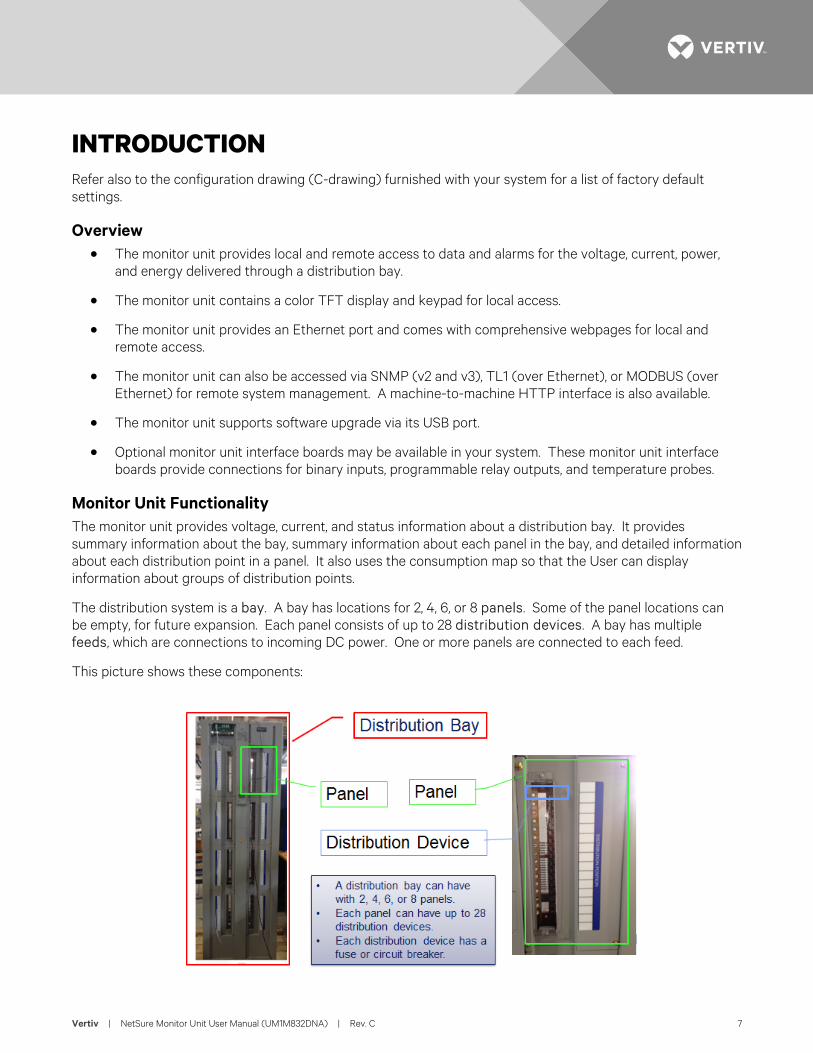
Monitor Unit Functionality The monitor unit provides voltage, current, and status information about a distribution bay. It provides summary information about the bay, summary information about each panel in the bay, and detailed information about each distribution point in a panel. It also uses the consumption map so that the User can display information about groups of distribution points.
The distribution system is a bay. A bay has locations for 2, 4, 6, or 8 panels. Some of the panel locations can be empty, for future expansion. Each panel consists of up to 28 distribution devices. A bay has multiple feeds, which are connections to incoming DC power. One or more panels are connected to each feed.
This picture shows these components:
Vertiv | NetSure Monitor Unit User Manual (UM1M832DNA) | Rev. C 8
There is monitor unit for each bay. It is a stand-alone unit that will not manage multiple bays and will not communicate back to the DC Power Plant which provides power to the bay. Distribution bays do not communicate with each other; instead, information from multiple distribution bays can be collected by a Network Management System.
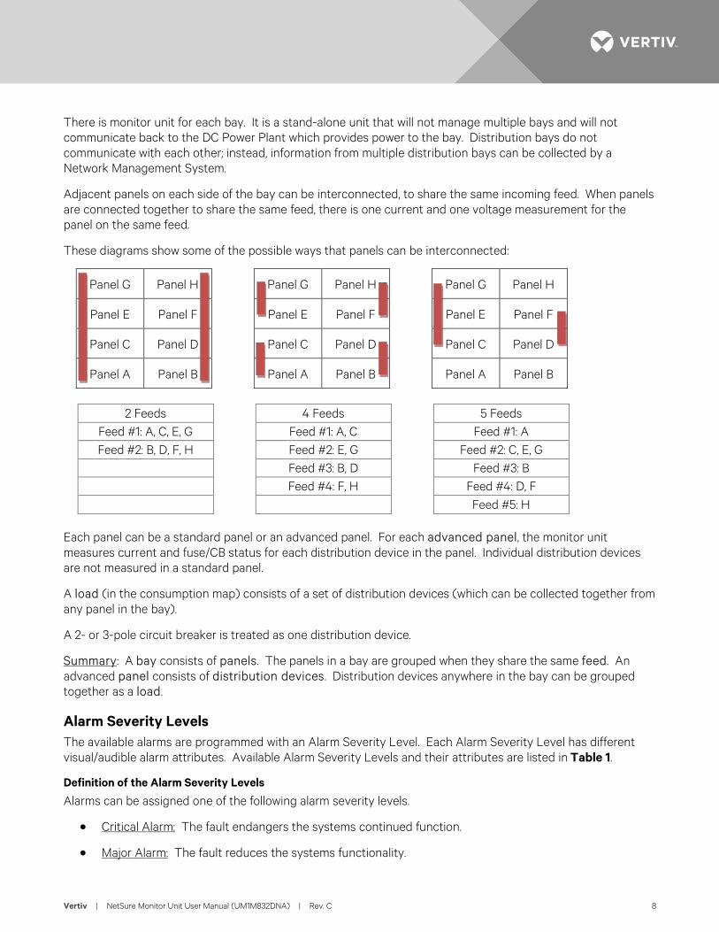
Adjacent panels on each side of the bay can be interconnected, to share the same incoming feed. When panels are connected together to share the same feed, there is one current and one voltage measurement for the panel on the same feed.
These diagrams show some of the possible ways that panels can be interconnected:
Panel G Panel H Panel G Panel H Panel G Panel H
Panel E Panel F Panel E Panel F Panel E Panel F
Panel C Panel D Panel C Panel D Panel C Panel D
Panel A Panel B Panel A Panel B Panel A Panel B
2 Feeds 4 Feeds 5 Feeds
Feed #1: A, C, E, G Feed #1: A, C Feed #1: A Feed #2: B, D, F, H Feed #2: E, G Feed #2: C, E, G
Feed #3: B, D Feed #3: B Feed #4: F, H Feed #4: D, F Feed #5: H
Each panel can be a standard panel or an advanced panel. For each advanced panel, the monitor unit measures current and fuse/CB status for each distribution device in the panel. Individual distribution devices are not measured in a standard panel.
A load (in the consumption map) consists of a set of distribution devices (which can be collected together from any panel in the bay).
A 2- or 3-pole circuit breaker is treated as one distribution device.
Summary: A bay consists of panels. The panels in a bay are grouped when they share the same feed. An advanced panel consists of distribution devices. Distribution devices anywhere in the bay can be grouped together as a load.
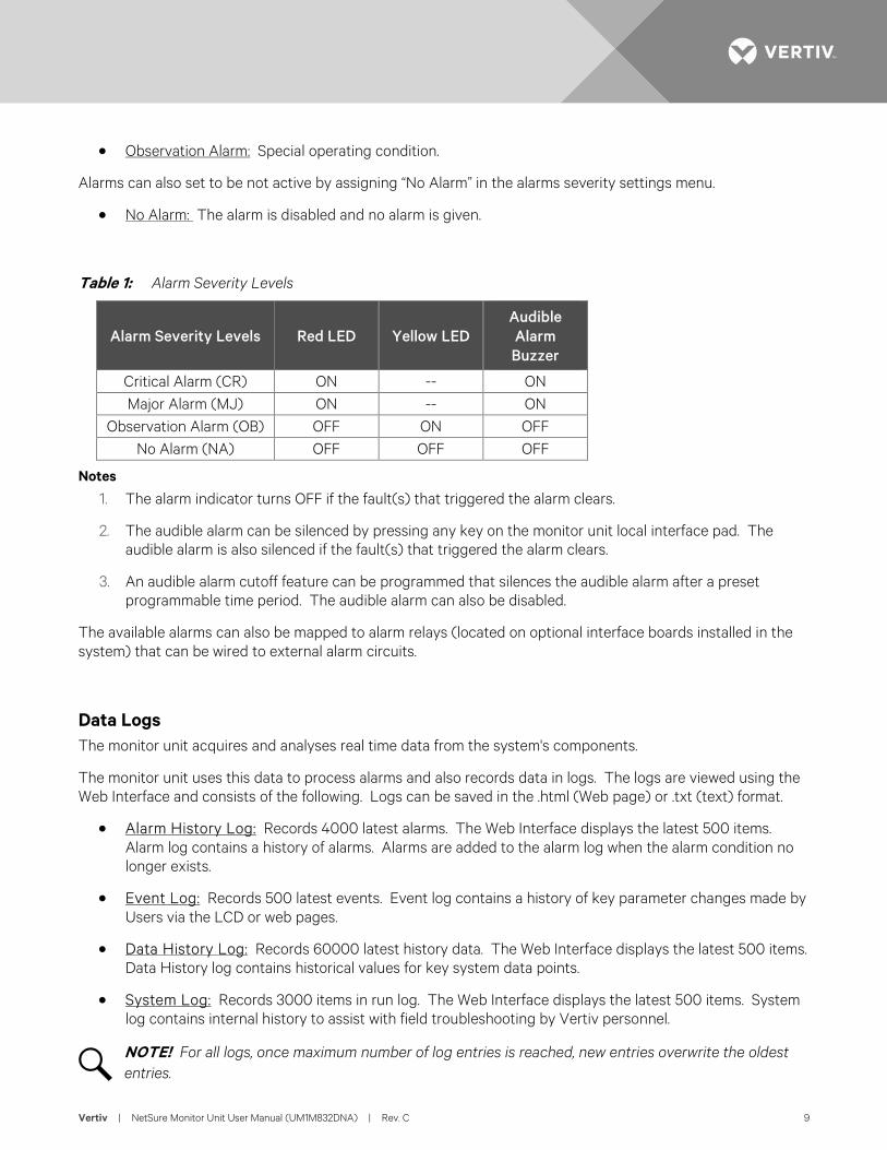
Alarm Severity Levels The available alarms are programmed with an Alarm Severity Level. Each Alarm Severity Level has different visual/audible alarm attributes. Available Alarm Severity Levels and their attributes are listed in Table 1.
Definition of the Alarm Severity Levels
Alarms can be assigned one of the following alarm severity levels.
• Critical Alarm: The fault endangers the systems continued function.
• Major Alarm: The fault reduces the systems functionality.
Vertiv | NetSure Monitor Unit User Manual (UM1M832DNA) | Rev. C 9
• Observation Alarm: Special operating condition.
Alarms can also set to be not active by assigning “No Alarm” in the alarms severity settings menu.
• No Alarm: The alarm is disabled and no alarm is given.
Table 1: Alarm Severity Levels
Alarm Severity Levels Red LED Yellow LED Audible Alarm Buzzer
Critical Alarm (CR) ON -- ON Major Alarm (MJ) ON -- ON
Observation Alarm (OB) OFF ON OFF No Alarm (NA) OFF OFF OFF
Notes
1. The alarm indicator turns OFF if the fault(s) that triggered the alarm clears.
2. The audible alarm can be silenced by pressing any key on the monitor unit local interface pad. The audible alarm is also silenced if the fault(s) that triggered the alarm clears.
3. An audible alarm cutoff feature can be programmed that silences the audible alarm after a preset programmable time period. The audible alarm can also be disabled.
The available alarms can also be mapped to alarm relays (located on optional interface boards installed in the system) that can be wired to external alarm circuits.
Data Logs The monitor unit acquires and analyses real time data from the system's components.
The monitor unit uses this data to process alarms and also records data in logs. The logs are viewed using the Web Interface and consists of the following. Logs can be saved in the .html (Web page) or .txt (text) format.
• Alarm History Log: Records 4000 latest alarms. The Web Interface displays the latest 500 items. Alarm log contains a history of alarms. Alarms are added to the alarm log when the alarm condition no longer exists.
• Event Log: Records 500 latest events. Event log contains a history of key parameter changes made by Users via the LCD or web pages.
• Data History Log: Records 60000 latest history data. The Web Interface displays the latest 500 items. Data History log contains historical values for key system data points.
• System Log: Records 3000 items in run log. The Web Interface displays the latest 500 items. System log contains internal history to assist with field troubleshooting by Vertiv personnel.
NOTE! For all logs, once maximum number of log entries is reached, new entries overwrite the oldest entries.
Vertiv | NetSure Monitor Unit User Manual (UM1M832DNA) | Rev. C 10
External Interface Functions 10M/100M Ethernet Port Located on Monitor Unit’s Top Panel
An RJ-45 10BaseT jack is provided on the top panel of the monitor unit for connection to a computer for local access to the monitor unit’s web pages or to a Local Area Network (LAN) for remote access to the monitor unit’s web pages. This port supports Dynamic Host Configuration Protocol (DHCP) function. For remote access, the communications cable should be a shielded cable.
NOTE! Some systems may have an IB4 board with a second Ethernet port. If your system has an IB4 board, DO NOT connect your Local Area Network (LAN) to the monitor unit’s top panel Ethernet port.
10M Ethernet Port Located on Optional IB4 Board (if furnished)
An RJ-45 10BaseT jack is provided on the IB4 board (if furnished in your system) for connection to a Local Area Network (LAN) for remote access to the monitor unit’s web pages. The communications cable should be a shielded cable.
IB (Interface Board) (if furnished)
Some systems may be furnished with an IB (Interface Board) connected to the monitor unit.
The IB2 (Interface Board) provides four (4) programmable form C-relay outputs.
The relay outputs can be connected to customer external alarm circuits. Each relay output can be configured to change state when one or more alarm events occur.
The relay outputs can also be connected to customer external equipment, so that the relay output can control or interface with the customer external equipment.
TL1
See “TL1 Interface” starting on page 32.
Machine-to-Machine HTTP Interface
See “Machine-to-Machine HTTP Interface” starting on page 33.
Consumption Map (when used with advanced distribution panels)
The monitor unit has a consumption map function accessible via the Web pages. A User can designate a system’s distribution device (connected to a customer load) to be monitored for consumption. Customer load consumption parameters for this distribution device are displayed on the consumption map Web page.
Refer to “Consumption Map Tab” on page 65. Refer also to “Consumption Map Settings Tab Programmable Parameter Descriptions” on page 69.
Vertiv | NetSure Monitor Unit User Manual (UM1M832DNA) | Rev. C 11
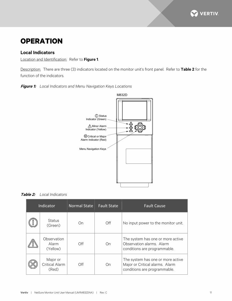
OPERATION Local Indicators Location and Identification: Refer to Figure 1.
Description: There are three (3) indicators located on the monitor unit’s front panel. Refer to Table 2 for the
function of the indicators.
Figure 1: Local Indicators and Menu Navigation Keys Locations
Table 2: Local Indicators
Indicator Normal State Fault State Fault Cause
Status
(Green) On Off No input power to the monitor unit.
Observation Alarm
(Yellow) Off On
The system has one or more active Observation alarms. Alarm conditions are programmable.
Major or Critical Alarm
(Red) Off On
The system has one or more active Major or Critical alarms. Alarm conditions are programmable.
Menu Navigation Keys
M832D
StatusIndicator (Green)
Minor AlarmIndicator (Yellow)
Critical or MajorAlarm Indicator (Red)
ESC ENT
Vertiv | NetSure Monitor Unit User Manual (UM1M832DNA) | Rev. C 12
Passwords and Privilege Levels Users (for local and Web access to the monitor unit) are configured via the Web Interface.
NOTE! Anyone can browse the monitor unit via the local keypad and display. A password is required to change settings. Web access always requires a User name and password to be entered to gain access.
Users are configured with a User Name, password, and privilege level.
User Name: Maximum 8 Characters (0-9, a-z, A-Z, _).
Password: Maximum 13 Characters (0-9, a-z, A-Z, _). Passwords must be at least six (6) characters long.
NOTE! Once there has been no activity (entering data, navigating between pages, etc.), the session is terminated and the User needs to enter the User name and password again.
Privilege Level: Refer to Table 3. A User has access to his/her privilege level menus, plus all menus of the lesser privilege levels.
Table 3: User Privilege Levels
Privilege Level Default User Name and Password
Authority
Level A (Browser) none set The User can only read (browse) information in the menus.
Level B (Operator) none set The User has access to the system "Control" menus.
Level C (Engineer) none set
The User has access to the system "Settings" menus and can download the configuration package. The User does not have access to update the OS application and modify, add, or delete Users.
Level D (Administrator) admin, 640275 The User has full access to all menus; including update the OS application and modify, add, and delete Users.
Multiple Languages Supported Multiple languages are supported in the Local Interface and Web Interface. Refer to “Language Tab” on page 94.
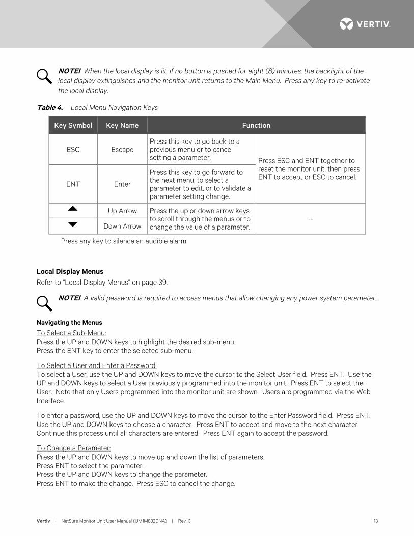
Using the Local Keypad and Display Local Menu Navigation Keys and Local Display Location and Identification: Refer to Figure 1.
Description: There are four (4) menu navigation keys and a local display located on the monitor unit’s front panel. Refer to Table 4 for the function of the menu navigation keys.
Vertiv | NetSure Monitor Unit User Manual (UM1M832DNA) | Rev. C 13
NOTE! When the local display is lit, if no button is pushed for eight (8) minutes, the backlight of the local display extinguishes and the monitor unit returns to the Main Menu. Press any key to re-activate the local display.
Table 4. Local Menu Navigation Keys
Key Symbol Key Name Function
ESC Escape Press this key to go back to a previous menu or to cancel setting a parameter. Press ESC and ENT together to
reset the monitor unit, then press ENT to accept or ESC to cancel.
ENT Enter
Press this key to go forward to the next menu, to select a parameter to edit, or to validate a parameter setting change.
Up Arrow Press the up or down arrow keys to scroll through the menus or to change the value of a parameter.
-- Down Arrow
Press any key to silence an audible alarm.
Local Display Menus Refer to “Local Display Menus” on page 39.
NOTE! A valid password is required to access menus that allow changing any power system parameter.
Navigating the Menus
To Select a Sub-Menu: Press the UP and DOWN keys to highlight the desired sub-menu. Press the ENT key to enter the selected sub-menu.
To Select a User and Enter a Password: To select a User, use the UP and DOWN keys to move the cursor to the Select User field. Press ENT. Use the UP and DOWN keys to select a User previously programmed into the monitor unit. Press ENT to select the User. Note that only Users programmed into the monitor unit are shown. Users are programmed via the Web Interface.
To enter a password, use the UP and DOWN keys to move the cursor to the Enter Password field. Press ENT. Use the UP and DOWN keys to choose a character. Press ENT to accept and move to the next character. Continue this process until all characters are entered. Press ENT again to accept the password.
To Change a Parameter: Press the UP and DOWN keys to move up and down the list of parameters. Press ENT to select the parameter. Press the UP and DOWN keys to change the parameter. Press ENT to make the change. Press ESC to cancel the change.
Vertiv | NetSure Monitor Unit User Manual (UM1M832DNA) | Rev. C 14
Using the Web Interface
Overview Via the Web Interface, a User (with proper access level) can:
• View real-time operating information.
• View and download information recorded in logs.
• Send control commands.
• Set programmable parameters.
• Download and upload configuration package.
• Download firmware to the monitor unit.
Multiple Browsers Supported Multiple browsers are supported in the Web Interface. The User can use Internet Explorer, Chrome, Safari, or Firefox.
Web Interface Screens Refer to “Web Interface Screens” on page 52.
Procedures Setting IPv4 Communications Parameters (if monitor unit not set as DHCP)
The monitor unit’s IPv4 parameters (IP, subnet mask, and gateway addresses) must be set to match your company’s network settings. The default settings for these parameters are shown below.
• IP Address: 192.168.1.2
• Subnet Mask Address: 255.255.255.0
• Gateway Address: 192.168.1.1
Local Menu Navigation: Main Menu / Settings Icon / Comm Settings / enter parameters.
Web Menu Navigation: Advance Settings Menu / Ethernet Tab / enter parameters.
Setting IPv6 Communications Parameters (if monitor unit not set as DHCPv6)
The monitor unit’s IPv6 parameters (IPv6 address, IPv6 prefix, and IPv6 gateway address) must be set to match your company’s network settings. The default settings for these parameters are shown below.
• Link-Local Address: fe80:209:f5ff:fe09:1002/64
• IPv6 Address: 20fa:fffd:fffc:fffb:fffa:fff9:fff8:fff7
• IPv6 Prefix: 0
• IPv6 Gateway: 20fa:1:fffe:ffff:fffe:fffd:ffff:fffe
Vertiv | NetSure Monitor Unit User Manual (UM1M832DNA) | Rev. C 15
Local Menu Navigation: Main Menu / Settings Icon / Comm Settings / enter parameters.
Web Menu Navigation: Advance Settings Menu / Ethernet Tab / enter parameters.
Setting for DHCP and DHCPv6
The DHCP and DHCPv6 functions allow the monitor unit to acquire an IP address automatically. This function can only be enabled or disabled via the local display and keypad. If this function is enabled and the acquisition of an IP address fails, an alarm is generated. If the acquisition of an IP address is successful, you need to record the IP address automatically acquired by the monitor unit to access the monitor unit via the Web Interface. This IP address is displayed on the main system info screen (Main Menu / ESC) in the IP Address field or in the local display menu (Main Menu / Settings Icon / Comm Settings) in the IP Address field below the DHCP setting.
Local Menu Navigation: Main Menu / Settings Icon / Comm Settings / DHCP (set to enabled) (can also view acquired IP address).
Main Menu / ESC (to view acquired IP address).
Web Menu Navigation: None.
Connecting the Monitor Unit to your Local Area Network (LAN) when the System is NOT Equipped with an IB4 Board
An Ethernet port is located on the top panel of the monitor unit. This port supports Dynamic Host Configuration Protocol (DHCP) function.
If your system does not have an IB4 board, connect the Local Area Network (LAN) to the monitor unit’s top panel port. This port can be assigned an IP address or can be set for DHCP. If set for DHCP, it will get its IP address from a DHCP server on the network. Refer to “Setting IPv4 Communications Parameters (if monitor unit not set as DHCP)” on page 14 or “Setting IPv6 Communications Parameters (if monitor unit not set as DHCPv6)” on page 14 to set the port parameters; or, “Setting for DHCP and DHCPv6” on page 15 to set the port as DHCP or DHCPv6.
Connecting the Monitor Unit to your Local Area Network (LAN) when the System IS Equipped with an IB4 Board
NOTE! Your system may be furnished with an IB4 board. The IB4 board provides a second Ethernet port. The Ethernet port located on the monitor unit’s top panel can ONLY be used to connect a computer directly to the monitor unit. The Ethernet port located on the IB4 board can be used to connect the monitor unit to your Local Area Network (LAN). Refer to your system’s documentation for location of the IB4 board (if furnished).
NOTE! If your system has an IB4 board, DO NOT connect your Local Area Network (LAN) to the monitor unit top Ethernet port.
Some systems may have an IB4 board with a second Ethernet port. This port supports Dynamic Host Configuration Protocol (DHCP) function. Refer to your system’s documentation for location of the IB4 board (if furnished).
Vertiv | NetSure Monitor Unit User Manual (UM1M832DNA) | Rev. C 16
If your system has an IB4 board, connect the Local Area Network (LAN) to the IB4 board port. The IB4 board port can be assigned an IP address or can be set for DHCP. If it is set for DHCP, it will get its IP address from a DHCP server on the network. Refer to “Setting IPv4 Communications Parameters (if monitor unit not set as DHCP)” on page 14 or “Setting IPv6 Communications Parameters (if monitor unit not set as DHCPv6)” on page 14 to set the port parameters; or, “Setting for DHCP and DHCPv6” on page 15 to set the port as DHCP or DHCPv6.
Connecting a Local Computer Directly to the Monitor Unit when the System is NOT Equipped with an IB4 Board
An Ethernet port is located on the top panel of the monitor unit. This port supports Dynamic Host Configuration Protocol (DHCP) function.
If your system does not have an IB4 board, perform the following procedure.
Procedure
1. Before connecting your computer directly to the monitor unit’s Ethernet port, use the following procedure to record your computer’s network settings (so they can be returned to these values when done) and then change these settings in your computer to match the communications settings programmed in the monitor unit.
NOTE! Windows 7 operating system is used in this procedure, other operating systems are similar.
a) Record your computer’s network settings by launching Control Panel in your computer. Navigate through Network and Sharing Center Local Area Connection Properties Internet Protocol Version 4 (TCP/IPV4) Properties.
b) Record whether the "Obtain an IP address automatically" or "Use the following IP address" button is selected. If "Use the following IP address" button is selected, also record the following:
IP Address: Subnet Mask: Default Gateway:
c) Record your monitor unit’s network settings by navigating the monitor unit’s local display panel to Main Menu / Settings Icon / Comm Settings. Record the following monitor unit’s IP parameters. If these parameters were not changed, they should be at the default values as shown in the example section below.
IPv4
IP Address: Subnet Mask: Default Gateway: Example: IP Address: 192.168.1.2 Subnet Mask: 255.255.255.0 Default Gateway: 192.168.1.1
IPv6
IPv6 Address: IPv6 Prefix:
Vertiv | NetSure Monitor Unit User Manual (UM1M832DNA) | Rev. C 17
IPv6 Gateway: Example: IPv6 Address: 20fa:fffd:fffc:fffb:fffa:fff9:fff8:fff7 IPv6 Prefix: 0 IPv6 Gateway: 20fa:1:fffe:ffff:fffe:fffd:ffff:fffe
d) Change your local computer’s network settings using the information you acquired in the above step, except that the last part of the IP address needs to be replaced with any different number.
IPv4
IP Address: Subnet Mask: Default Gateway: Example: IP Address: 192.168.1.3 Subnet Mask: 255.255.255.0 Default Gateway: 192.168.1.1
IPv6
IPv6 Address: IPv6 Prefix: IPv6 Gateway: Example: IPv6 Address: 20fa:fffd:fffc:fffb:fffa:fff9:fff8:fff7 IPv6 Prefix: 0 IPv6 Gateway: 20fa:1:fffe:ffff:fffe:fffd:ffff:fffe
e) Select OK. Note that you may have to reboot your local computer for the settings to take effect. Follow any instruction you see on the screen.
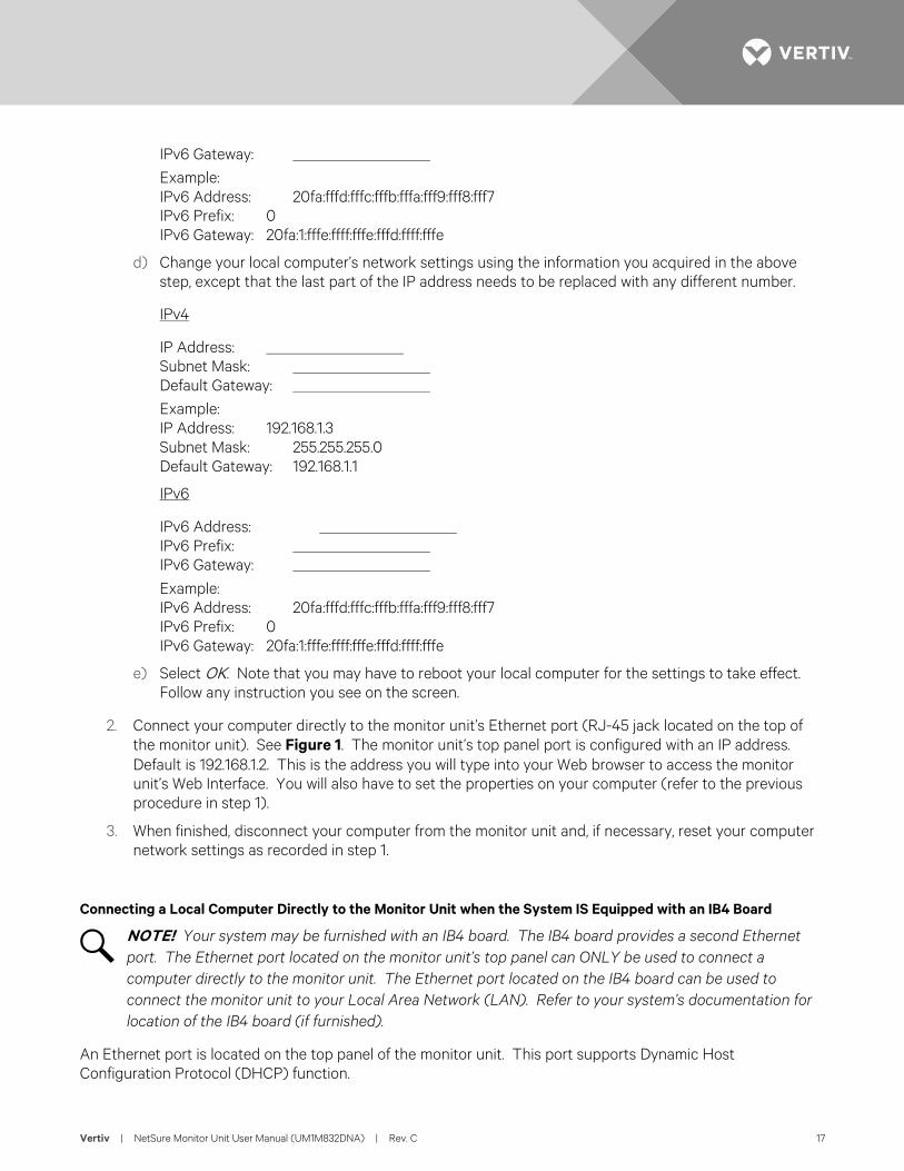
2. Connect your computer directly to the monitor unit’s Ethernet port (RJ-45 jack located on the top of the monitor unit). See Figure 1. The monitor unit’s top panel port is configured with an IP address. Default is 192.168.1.2. This is the address you will type into your Web browser to access the monitor unit’s Web Interface. You will also have to set the properties on your computer (refer to the previous procedure in step 1).
3. When finished, disconnect your computer from the monitor unit and, if necessary, reset your computer network settings as recorded in step 1.
Connecting a Local Computer Directly to the Monitor Unit when the System IS Equipped with an IB4 Board
NOTE! Your system may be furnished with an IB4 board. The IB4 board provides a second Ethernet port. The Ethernet port located on the monitor unit’s top panel can ONLY be used to connect a computer directly to the monitor unit. The Ethernet port located on the IB4 board can be used to connect the monitor unit to your Local Area Network (LAN). Refer to your system’s documentation for location of the IB4 board (if furnished).
An Ethernet port is located on the top panel of the monitor unit. This port supports Dynamic Host Configuration Protocol (DHCP) function.
Vertiv | NetSure Monitor Unit User Manual (UM1M832DNA) | Rev. C 18
Some systems may have an IB4 board with a second Ethernet port. Refer to your system’s documentation for location of the IB4 board (if furnished).
If your system has an IB4 board, perform the following procedure.
Procedure
1. Connect your computer directly to the monitor unit’s Ethernet port (RJ-45 jack located on the top of the monitor unit). See Figure 1. The monitor unit’s top panel port will have the following IPv4 Address: 192.168.100.100. Enter the address 192.168.100.100 in your Web browser to access the monitor unit’s Web Interface via IPv4. The monitor unit’s top panel port will have the following IPv6 Address. IPv6 Link-Local Address: fe80::209:f5ff:fe09:1002/64 or IPv6 Address: 20fa:fffd:fffc:fffb:fffa:fff9:fff8:fff7. Enter the IPv6 Link-Local Address: [fe80::209:f5ff:fe09:1002/64] or IPv6 Address: [20fa:fffd:fffc:fffb:fffa:fff9:fff8:fff7] to access the monitor unit’s Web Interface via IPv6.
2. When finished, disconnect your computer from the monitor unit.
Disabling Proxy Server Settings to Enable a Connection to the Monitor Unit over an Intranet Network (if required)
NOTE! This procedure needs to be performed only when the monitor unit is connected to an Intranet and the User’s computer is set to access the Intranet through a proxy server. Note that if the monitor unit is connected to the Internet and the User’s computer is connected to an Intranet, the User may not be able to disable the proxy server and access the monitor unit.
If the monitor unit’s Ethernet port is connected to your company’s Intranet Network and your computer is also connected to the Intranet Network but requires access via a proxy server, you must disable the proxy server settings to access the monitor unit. Follow the procedure below to disable the proxy server settings.
Procedure
NOTE! Internet Explorer is used in this procedure, other browsers are similar.
1. Launch “Internet Explorer”.
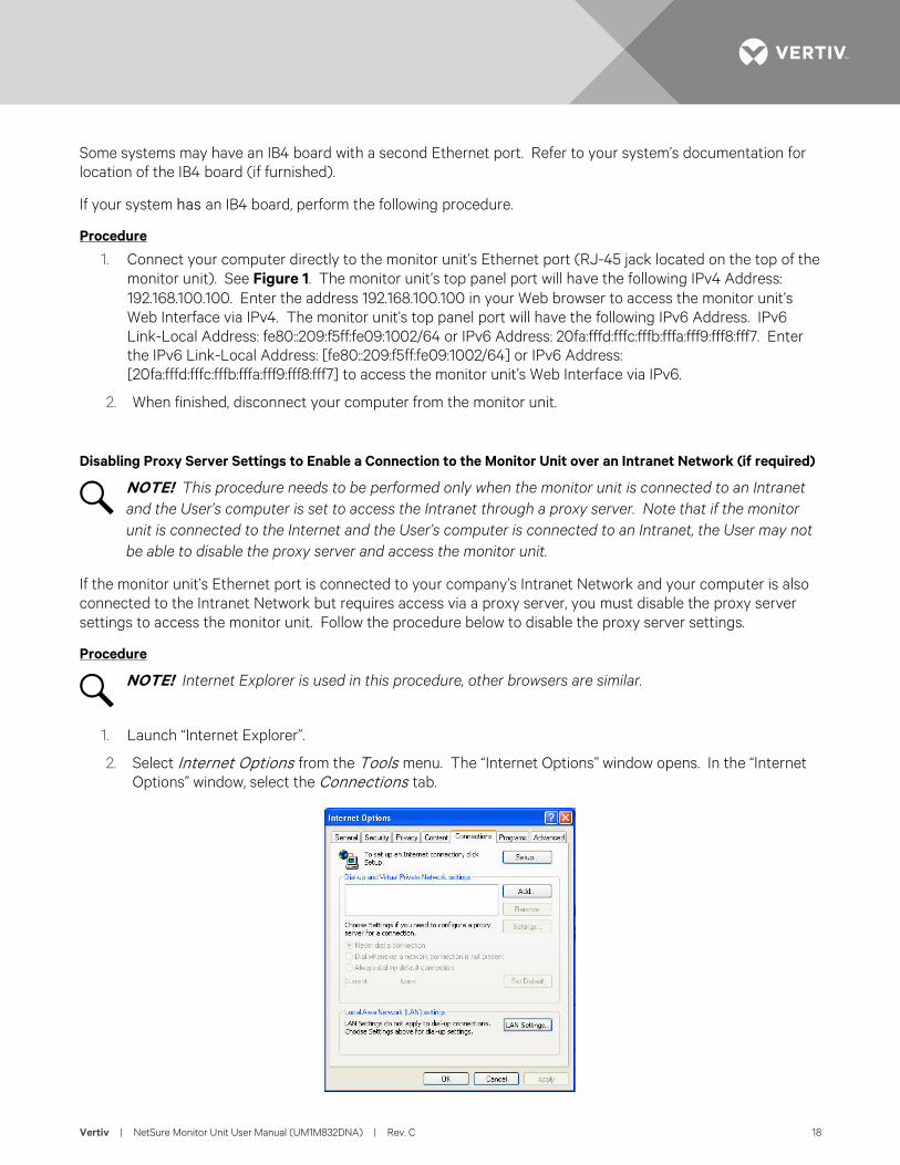
2. Select Internet Options from the Tools menu. The “Internet Options” window opens. In the “Internet Options” window, select the Connections tab.
Vertiv | NetSure Monitor Unit User Manual (UM1M832DNA) | Rev. C 19
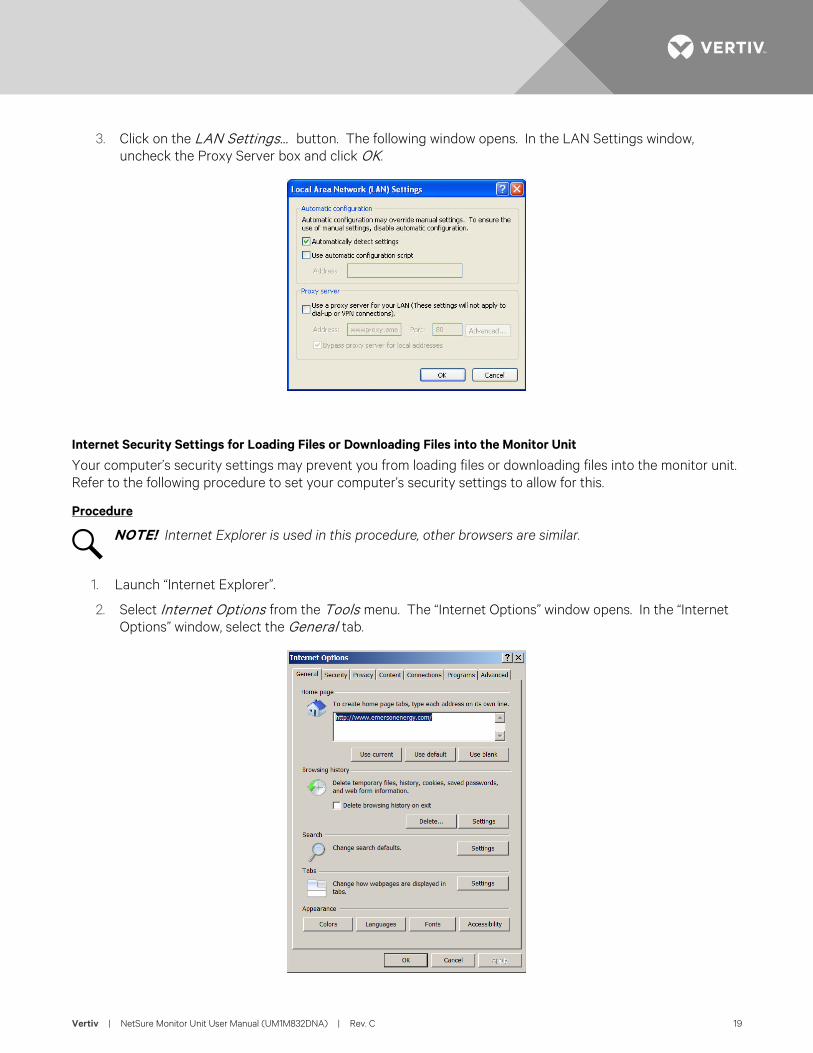
3. Click on the LAN Settings... button. The following window opens. In the LAN Settings window, uncheck the Proxy Server box and click OK.
Internet Security Settings for Loading Files or Downloading Files into the Monitor Unit
Your computer’s security settings may prevent you from loading files or downloading files into the monitor unit. Refer to the following procedure to set your computer’s security settings to allow for this.
Procedure
NOTE! Internet Explorer is used in this procedure, other browsers are similar.
1. Launch “Internet Explorer”.
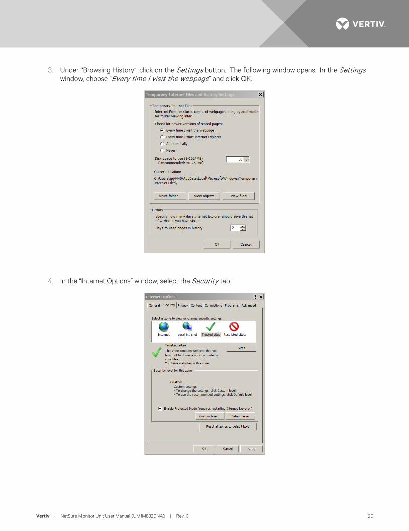
2. Select Internet Options from the Tools menu. The “Internet Options” window opens. In the “Internet Options” window, select the General tab.
Vertiv | NetSure Monitor Unit User Manual (UM1M832DNA) | Rev. C 20
3. Under “Browsing History”, click on the Settings button. The following window opens. In the Settings window, choose “Every time I visit the webpage” and click OK.
4. In the “Internet Options” window, select the Security tab.
Vertiv | NetSure Monitor Unit User Manual (UM1M832DNA) | Rev. C 21
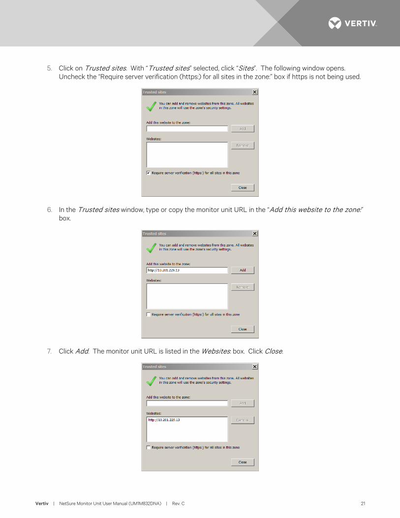
5. Click on Trusted sites. With “Trusted sites” selected, click “Sites”. The following window opens. Uncheck the “Require server verification (https:) for all sites in the zone:” box if https is not being used.
6. In the Trusted sites window, type or copy the monitor unit URL in the “Add this website to the zone:” box.
7. Click Add. The monitor unit URL is listed in the Websites: box. Click Close.
Vertiv | NetSure Monitor Unit User Manual (UM1M832DNA) | Rev. C 22
Logging into the Monitor Unit
Procedure
Internet Explorer, version 6 or newer, is supported (IE 8.0 is recommended). Chrome, Safari, and Firefox are also supported.
1. In your browser, enter http:// and the monitor unit’s IP address (see “Connecting a Local Computer Directly to the Monitor Unit when the System is NOT Equipped with an IB4 Board” on page 16 or “Connecting a Local Computer Directly to the Monitor Unit when the System IS Equipped with an IB4 Board” on page 17) and press ENTER. If your site requires secure HTTP and you were furnished with an monitor unit configuration with secure HTTP, enter https:// and the monitor unit’s IP address and press ENTER.
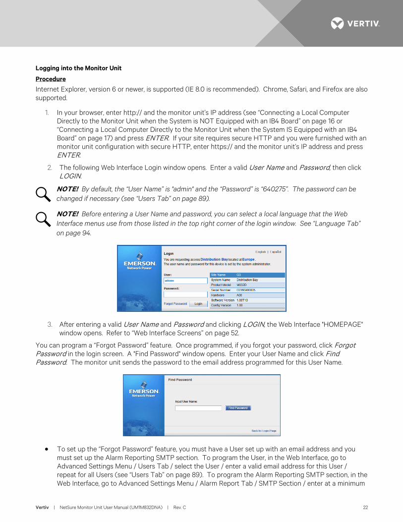
2. The following Web Interface Login window opens. Enter a valid User Name and Password, then click LOGIN.
NOTE! By default, the “User Name” is "admin" and the “Password” is “640275”. The password can be changed if necessary (see “Users Tab” on page 89).
NOTE! Before entering a User Name and password, you can select a local language that the Web Interface menus use from those listed in the top right corner of the login window. See “Language Tab” on page 94.
3. After entering a valid User Name and Password and clicking LOGIN, the Web Interface "HOMEPAGE" window opens. Refer to “Web Interface Screens” on page 52.
You can program a “Forgot Password” feature. Once programmed, if you forgot your password, click Forgot Password in the login screen. A "Find Password" window opens. Enter your User Name and click Find Password. The monitor unit sends the password to the email address programmed for this User Name.
• To set up the “Forgot Password” feature, you must have a User set up with an email address and you must set up the Alarm Reporting SMTP section. To program the User, in the Web Interface, go to Advanced Settings Menu / Users Tab / select the User / enter a valid email address for this User / repeat for all Users (see “Users Tab” on page 89). To program the Alarm Reporting SMTP section, in the Web Interface, go to Advanced Settings Menu / Alarm Report Tab / SMTP Section / enter at a minimum
Vertiv | NetSure Monitor Unit User Manual (UM1M832DNA) | Rev. C 23
the following parameters: “Email To” address, Server IP (IPV4 Server address), Server Port, “Email From” address. If email authentication is required, then the SMTP Account and SMTP Password needs to be configured as well. (See “Alarm Report Tab” on page 104.)
Common Tasks Performed via the Local Keypad and/or Web Interface Procedures Refer also to “Local Display Menus” on page 39 and “Web Interface Screens” on page 52 for menu item descriptions.
NOTE! Ensure current configuration is backed up prior to changing settings (see “Backing Up the Monitor Unit Configuration” on page 28). Create new backup files after every successful update for your records and in case of monitor unit failure.
Setting Bay Parameters
Local Menu Navigation: Main Menu / Settings Icon / Bay Settings.
Web Menu Navigation: Home Page / Distribution Bay Tab / see “Distribution Bay Settings Web Page” on page 56.
Setting Input Feeds Parameters
Local Menu Navigation: Main Menu / Settings Icon / Feeds Settings.
Web Menu Navigation: Home Page / Distribution Bay Tab / see “Feed Settings Web Page” on page 58.
Setting Distribution Panels Parameters
Local Menu Navigation: Main Menu / Settings Icon / Panel Settings.
Web Menu Navigation: Home Page / Distribution Bay Tab / see “Standard Distribution Panel Settings Web Page” on page 61 and “Advanced Distribution Panel Settings Web Page” on page 63.
Changing the Date and Time
Local Menu Navigation: Main Menu / Settings Icon / Sys Settings / Date. Main Menu / Settings Icon / Sys Settings / Time.
Vertiv | NetSure Monitor Unit User Manual (UM1M832DNA) | Rev. C 24
Date: Use the Up Arrow and Down Arrow to select the date field. Press ENT. Use Up Arrow and Down Arrow to select the year then press ENT, next use Up Arrow and Down Arrow to select the month then press ENT, and finally use Up Arrow and Down Arrow to select the day then press ENT.
Time: Use the Up Arrow and Down Arrow to select the time field. Press ENT. Use Up Arrow and Down Arrow to select the hour then press ENT, next use Up Arrow and Down Arrow to select the minute then press ENT, and finally use Up Arrow and Down Arrow to select the second then press ENT.
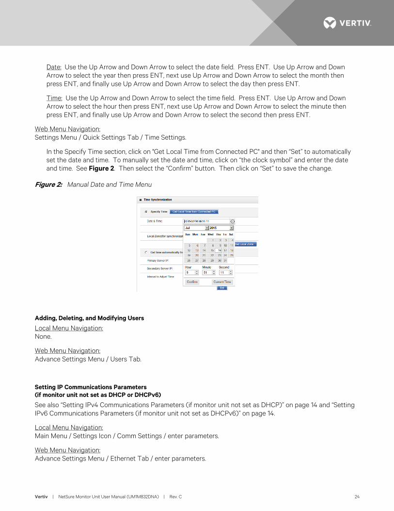
Web Menu Navigation: Settings Menu / Quick Settings Tab / Time Settings.
In the Specify Time section, click on "Get Local Time from Connected PC" and then “Set” to automatically set the date and time. To manually set the date and time, click on “the clock symbol” and enter the date and time. See Figure 2. Then select the “Confirm” button. Then click on “Set” to save the change.
Figure 2: Manual Date and Time Menu
Adding, Deleting, and Modifying Users
Local Menu Navigation: None.
Web Menu Navigation: Advance Settings Menu / Users Tab.
Setting IP Communications Parameters (if monitor unit not set as DHCP or DHCPv6)
See also “Setting IPv4 Communications Parameters (if monitor unit not set as DHCP)” on page 14 and “Setting IPv6 Communications Parameters (if monitor unit not set as DHCPv6)” on page 14.
Local Menu Navigation: Main Menu / Settings Icon / Comm Settings / enter parameters.
Web Menu Navigation: Advance Settings Menu / Ethernet Tab / enter parameters.
Vertiv | NetSure Monitor Unit User Manual (UM1M832DNA) | Rev. C 25
Setting for DHCP and DHCPv6
The DHCP and DHCPv6 functions allow the monitor unit to acquire an IP address automatically. This function can only be enabled or disabled via the local display and keypad. If this function is enabled and the acquisition of an IP address fails, an alarm is generated. If the acquisition of an IP address is successful, you need to record the IP address automatically acquired by the monitor unit to access the monitor unit via the Web Interface. This IP address is displayed on the main system info screen (Main Menu / ESC) in the IP Address field or in the local display menu (Main Menu / Settings Icon / Comm Settings) in the IP Address field below the DHCP setting.
Local Menu Navigation: Main Menu / Settings Icon / Comm Settings / DHCP (set to enabled) (can also view acquired IP address).
Main Menu / ESC (to view acquired IP address).
Web Menu Navigation: None.
Setting SNMP Parameters
Local Menu Navigation: None.
Web Menu Navigation: Advance Settings Menu / SNMP Tab.
Setting TL1 Parameters
Refer to the following procedures.
Setting TL1 Protocol Parameters
Local Menu Navigation: None.
Web Menu Navigation: Advance Settings Menu / Monitor Protocol Tab (set to TL1), then click the “Valid after Restart" button. Set the TL1 protocol parameters as described under “TL1 Protocol” on page 116.
Setting TL1 Access Identifiers and Sub-Access Identifiers
Local Menu Navigation: None.
Web Menu Navigation: Advance Settings Menu / TL1 AID Group Tab. Set the TL1 access identifiers and sub-access identifiers as described under “TL1 AID Group Tab” on page 118.
Enabling/Disabling and Configuring Pre-Defined TL1 Signals
Local Menu Navigation: None.
Vertiv | NetSure Monitor Unit User Manual (UM1M832DNA) | Rev. C 26
Web Menu Navigation: Advance Settings Menu / TL1 AID Signal Tab. Assign signals to the TL1 access identifiers as described under “TL1 AID Signal Tab” on page 120.
Assigning Severity Level to Alarms
Local Menu Navigation: None.
Web Menu Navigation: Advance Settings Menu / Alarms Tab and DI Alarms Tab.
Assigning Relays to Alarms
Local Menu Navigation: None.
Web Menu Navigation: Advance Settings Menu / Alarms Tab and DI Alarms Tab.
Setting Digital Inputs
Local Menu Navigation: None.
Web Menu Navigation: Advance Settings Menu / DI Alarms Tab
Disabling the Local Keypad Sound
Local Menu Navigation: Main Menu / Settings Icon / Sys Settings / Keypad Voice.
Web Menu Navigation: None.
Programming the Audible Alarm Feature
Local Menu Navigation: Main Menu / Settings Icon / Sys Settings / Audible Alarm.
Web Menu Navigation: None.
Blocking Alarms
Local Menu Navigation: None.
Vertiv | NetSure Monitor Unit User Manual (UM1M832DNA) | Rev. C 27
Web Menu Navigation: Settings Menu / Quick Settings Tab / Outgoing Alarms Blocked.
Viewing Alarms
Local Menu Navigation: Main Menu / Alarm Icon / ENT.
Web Menu Navigation: Active alarms are listed in the lower right window pane. If the window pane is collapsed, click the "arrow" icon to expand the alarm list.
Viewing System Status
Local Menu Navigation: Main Menu / Bay Current Icon / ENT. Main Menu / Input Feeds Current and Voltage Icon / ENT. Main Menu / Distribution Panel Icons / ENT.
Web Menu Navigation: System status is displayed in the right window pane of the Home page. Select the Distribution Bay tab and use the interactive links to view the various system elements status pages. Select the Bay Data tab to view basic bay data. See “Distribution Bay Tab” on page 55 and “Consumption Map Tab” on page 65.
Viewing the Monitor Unit’s Device Inventory
Local Menu Navigation: Main Menu / ESC to view Info Screens / ENT to view Inventory.
Web Menu Navigation: System Inventory Menu.
Clearing Data
Local Menu Navigation: Main Menu / Settings Icon / select “Clear Datas” in the various settings menus.
Web Menu Navigation: Home Page / Distribution Bay Tab / navigate the various interactive elements screens and select Clear Data in the settings screens.
Clearing Logs
Local Menu Navigation: None.
Web Menu Navigation: Advance Settings Menu / Clear Data Tab / select log to clear.
Vertiv | NetSure Monitor Unit User Manual (UM1M832DNA) | Rev. C 28
Using the Relay Test Feature
NOTE! The relay test can only be performed when no alarms are present.
Refer to the following procedures.
Automatic Test
When placed in Relay Automatic Test Mode; all relays on an IB2 board de-energize (since Fail Safe is enabled, relay 1on the 1st IB2 will be in alarm state, if wired for fail safe), then one-by-one each relay energizes for the time period selected and then de-energizes. Relay 1 will stay in the alarm state during the rest of the relay tests.
Local Menu Navigation: None.
Web Menu Navigation: Advance Settings Menu / DO (Relay) Tab / set the Relay Test Time. then Advance Settings Menu / DO (Relay) Tab / Relay Test (set to Automatic).
NOTE! The relay test can be exited at any time by setting the Relay Test to Disabled.
Manual Test
When placed in Relay Manual Test Mode, all relays on an interface board de-energize (since Fail Safe is enabled relay 1 on the IB2 will be in alarm state, if wired for fail safe). Then you can individually change each relay’s state. The relay changes state for the time period selected. At the end of the test, all relays are returned to their normal state (if no alarms are present).
Local Menu Navigation: None.
Web Menu Navigation: Advance Settings Menu / DO (Relay) Tab / Relay Test (set to Manual). then Advance Settings Menu / DO (relay) / Relay (select the other state) then press the SET button. then Advance Settings Menu / DO (Relay) Tab / Relay Test (set to Disabled).
Backing Up the Monitor Unit Configuration
There are two steps in backing up the system’s monitor unit configuration:
• Save the monitor unit configuration package. This package includes the base configuration and any changes made to alarm severity levels, relay assignments, and signal names.
ALERT! This file is NOT forward compatible.
• Save a file named "SettingParam.tar". This file contains changes made to system parameter settings and alarm setpoints. A file named "SettingParam.tar" is automatically created/appended by the monitor unit whenever a User (or the factory at the time of shipment) makes changes to parameter settings via the
Vertiv | NetSure Monitor Unit User Manual (UM1M832DNA) | Rev. C 29
local display or Web Interface. This file can be saved to your computer so you can restore any custom settings you may have made.
NOTE! It is strongly recommended that you save a copy of the SettingParam.tar file whenever you customize any parameter settings. Then, if you ever replace the monitor unit or perform a "Restore Defaults" procedure, you can restore your customized settings by downloading the previously saved SettingParam.tar file back into the monitor unit.
Prior to changing settings, ensure the current configuration package and "SettingParam.tar" files are backed up. After making changes, create new backup files.
To aid in file management, you may change the name of the configuration package "app_cfg.tar" to differentiate it from other "app_cfg.tar" files saved. The new name can use alpha and numeric characters preceding the original "app_cfg.tar" name (the end of the new file name must always be "app_cfg.tar"; for example, an acceptable filename would be "seville4app_cfg.tar").
To aid in file management, you may change the name of the "SettingParam.tar" file to differentiate it from other "SettingParam.tar" files saved. The new name can use alpha and numeric characters preceding the original "SettingParam.tar" name (the end of the new file name must always be "SettingParam.tar"; for example, an acceptable filename would be "seville4SettingParam.tar").
Refer to the following procedures.
Saving the Configuration Package
Local Menu Navigation: None.
Web Menu Navigation: Advance Settings Menu / SW Maintenance Tab. See “Upload/Download Procedure” on page 99 to save the "Configuration Package" to your computer.
Saving the SettingParam.tar File
Local Menu Navigation: None.
Web Menu Navigation: Advance Settings Menu / SW Maintenance Tab. See “Retrieve SettingParam.tar Procedure” on page 98 to retrieve the SettingParam.tar file.
Reloading a Backed-Up Monitor Unit Configuration
There are two steps in reloading a backed-up monitor unit configuration.
• One step to reload the saved monitor unit configuration package.
• One step to reload the saved "SettingParam.tar" file.
Refer to the following procedures.
Reloading the Configuration Package
Local Menu Navigation: None.
Vertiv | NetSure Monitor Unit User Manual (UM1M832DNA) | Rev. C 30
Web Menu Navigation: Advance Settings Menu / SW Maintenance Tab. See “Upload/Download” on page 99 to download a configuration package into the monitor unit.
Reloading the SettingParam.tar File
Local Menu Navigation: None.
Web Menu Navigation: Advance Settings Menu / SW Maintenance Tab. See “Upload/Download Procedure” on page 99 to download a "SettingParam.tar" file into the monitor unit.
Upgrading the Monitor Unit Using an Application ("All") Package
This procedure is typically used to upgrade your monitor unit when a new release of firmware is available for you application. The name of the Application "All" Package file must end in .tar or .tar.gz. An Application “All” package file has both the application (software) and configuration package and is usually supplied for an application upgrade.
A User can copy an Application ("All") Package from your computer to a USB memory device. You can then place the USB memory device into the monitor unit USB port and then download the file into the monitor unit. If upgrading the monitor unit with a USB drive other than the supplied USB, the following USB drive specifications must be adhered to:
• USB 2.0 or below, 32G or less, formatted fat32 file system.
Refer to the following procedures.
Local Menu Navigation (To Download an Application ("All") Package):
1. Copy the file to a USB memory device. The file must be in the root directory of the USB memory device. The file must be named app_V#.#.##.tar.gz.
NOTE! #.#.## is the revision number (i.e. 1.1.40, 4.1.40, etc.).
2. Connect the USB memory device to the USB port on the top of the monitor unit.
3. Navigate to “Main Menu / Settings Icon / Sys Settings / Update App / select yes”. Once Yes is selected and confirmed, the configuration file located on the memory device located in the monitor unit's USB port is loaded into the monitor unit.
4. Return to the Main Screen, and then reboot the monitor unit (press ENT and ESC at the same time).
5. The screen displays "OK to reboot? ESC to cancel! ENT to OK." Press ENT to reboot.
6. The monitor unit enters an initialization routine, which takes a few minutes. The routine is complete and the monitor unit is operational when normal system voltage is displayed on the screen.
7. Remove the memory device.
Web Menu Navigation (To Download an Application ("All") Package):
Advance Settings Menu / SW Maintenance Tab. See “Upload/Download Procedure” on page 99 to download an Application (“All”) Package into the monitor unit.
Vertiv | NetSure Monitor Unit User Manual (UM1M832DNA) | Rev. C 31
Restoring Factory Default Configuration
This procedure is typically used to restore any changes made to any settings, relay assignments, alarm severities, or signal names. This file is not shipped with the system. There are one or two steps required to restore your monitor unit as shipped.
• One step to restore the factory default configuration (required only if you made any changes to relay assignments, alarm severities, or signal names).
• One step to reload the "SettingParam.tar" file (required only if you made any system parameter settings and alarm setpoints change).
Your system may have been configured for specific options at the factory which creates a “SettingParam.tar” file. Restoring the factory default configuration returns the system to the settings of the default configuration. These are the settings before specific options may have been configured by the factory. To restore the system to the settings as shipped, after restoring the factory default configuration, you must reload the factory “SettingParam.tar” file.
NOTE! If a system was shipped with factory modified settings, the system may be supplied with a USB memory device that contains a “SettingParam.tar” file as shipped. If provided, the “SettingParam.tar” file has a seven-digit UIN (Unique Identification Number) preceding the “SettingParam.tar” filename. The UIN identifies a “SettingParam.tar” file for use with a specific system. This file can be used to restore your system to the configuration as shipped. Refer to “Reloading a Backed-Up Monitor Unit Configuration” on page 29 to reload the supplied “SettingParam.tar” file.
Procedure
ALERT! When this procedure is performed, the monitor unit’s existing configuration and parameter settings will be lost. The “SettingParam.tar” file is deleted. Before restoring the factory default configuration, if you have made changes to any setting save the “SettingParam.tar” file or if you have made any name changes, relay assignments, or alarm severities save the configuration package (see Backing Up the Monitor Unit Configuration on page 28).
AFTER PERFORMING THIS PROCEDURE, RELOAD THE “SETTINGPARAM.TAR” FILE AND CONFIGURATION PACKAGE, IF REQUIRED.
Local Menu Navigation: Main Menu / Settings Icon / Sys Settings / Restore Default.
Web Menu Navigation: Advance Settings Menu / SW Maintenance Tab. See “Restore Factory Default Configuration Procedure” on page 96.
Rebooting the Monitor Unit
Local Menu Navigation: At the Main Screen, press ENT and ESC at the same time to reset the monitor unit.
Web Menu Navigation: Advance Settings Menu / SW Maintenance Tab / Reboot Controller button.
Vertiv | NetSure Monitor Unit User Manual (UM1M832DNA) | Rev. C 32
Changing the Names of Items Displayed in the LCD and Web-Interface Menus
Local Menu Navigation: None.
Web Menu Navigation: In the following settings menus, enter a name and press “set”.
Distribution Bay
Home Page / Distribution Bay Tab / see “Distribution Bay Settings Web Page” on page 56.
Input Feeds
Home Page / Distribution Bay Tab / see “Feed Settings Web Page” on page 58.
Distribution Panels
Home Page / Distribution Bay Tab / see “Standard Distribution Panel Settings Web Page” on page 61 and “Advanced Distribution Panel Settings Web Page” on page 63.
Web Menu Navigation: For digital inputs and relays, navigate to the “DO (Relay)” tab in the Advance Settings menu. Press “Modify” and enter the signal name parameter(s). When done, press “Set”.
Relay Outputs
Advance Settings Menu / DO (relay) Tab.
TL1 Interface TL1 is available as an orderable option.
General The monitor unit can operate as a Network Element (NE) in a Network Maintenance and Administration (NMA) system. NMA is software developed by Bell Communications Research (Bellcore) to run on an Operations System (OS). This system utilizes the Transaction Language 1 (TL1) command language.
It is beyond the scope of this manual to provide operational instructions for an NMA system and TL1 commands. Refer to the NMA system documentation and the appropriate Bellcore publications for operational instructions.
Specifically, refer to the current issue of the following Bellcore publications for further information on the NMA system and TL1 command language.
TR-NWT-000831 TR-NWT-000833 TR-NWT-000835 TR-NWT-000199 TA-NWT-000199 TA-NWT-000200 TA-NWT-001360
Vertiv | NetSure Monitor Unit User Manual (UM1M832DNA) | Rev. C 33
Monitor Unit TL1 Feature The monitor unit can send and receive TL1 messages and responses between itself and a customer client application. This includes autonomous messages sent by the monitor unit to notify the customer client application of alarms.
TL1 messages contain parameter values that indicate attributes and the state associated to signals. The monitor unit provides configuration parameters for all signals as needed to specify values of the TL1 attributes and states that are required in the TL1 messages. Configuration of TL1 attribute parameters is accessed through the WEB interface.
Monitor Unit TL1 Port
The monitor unit TL1 port transports TL1 messages between the monitor unit and a customer network operations center or client. Access through this interface is restricted to a User who logs on with the TL1 ‘ACTIVATE-USER’ request message.
The monitor unit TL1 port uses the telnet protocol (not SSH) over the monitor unit’s Ethernet connection and has requirements for specific operational settings. The monitor unit supports TL1 telnet operation over IPV4 and IPV6 networks. The monitor unit TL1 port is enabled and configured through the WEB interface.
Only one telnet connection through the monitor unit TL1 port is allowed at any time. The telnet connection is disabled when the TL1 interface is not selected by the customer. The telnet connection is considered disabled when all telnet ports indicate closed during a network scan of the Ethernet connection.
Monitor Unit TL1 Configuration
Webpages are provided in the monitor unit Web interface to configure signal parameters and settings that specify the signal’s TL1 attributes. See “Setting TL1 Parameters” on page 25.
Machine-to-Machine HTTP Interface Description This interface option must be specified when the system is ordered. It is enabled or disabled at the factory.
The Machine-to-Machine HTTP Interface option provides the ability for a machine to poll the monitor unit using a special URL for a pre-configured packet of information using HTTP-GET.
The URL requests are sent to the monitor unit using the same port as HTTP. Note this function is not available over HTTPS. This interface assumes that the customer is on a secured network.
The interface can be used to retrieve data using third-party programs such as WGET and CURL.
The interface works with IPv4 and IPv6.
The interface is available from the monitor unit when the monitor unit uses a fixed IP address or a DHCP address.
The interface only supports one request/query at a time.
Using the Machine-to-Machine HTTP Interface Option Refer to the following.
Vertiv | NetSure Monitor Unit User Manual (UM1M832DNA) | Rev. C 34
Request
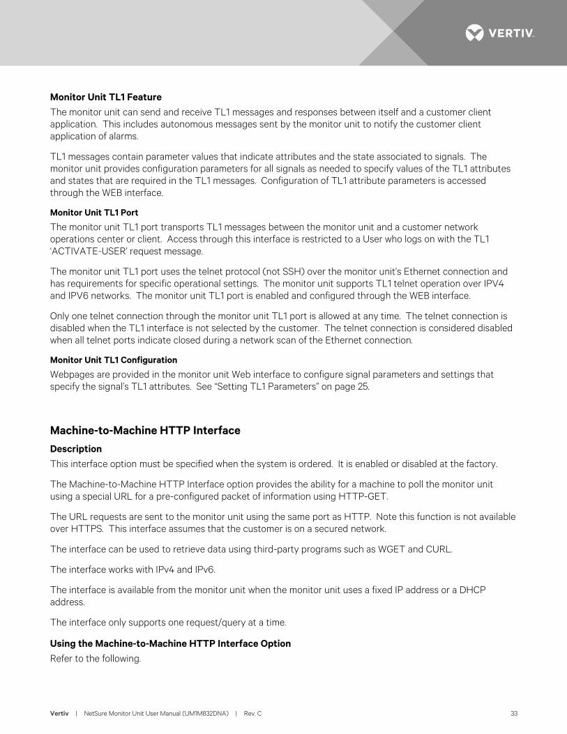
The request consists of the scheme (http), authority (the IP address of the monitor unit), the path (/data), and the query. The end of the query can be specified by # or by the end of the URL. Fragments are not supported.
The URL address should include /data; otherwise, it is not processed by this feature. The URL address can contain /data? or /data/?.
The query (input parameters) in the request starts after the question mark (?).
There is an ampersand (&) between each field in the query.
The fields in the query can appear in any order.
The fields in the query are the starting time, the ending time, and 0 to 3 user keys. The starting time is assumed to be 4 hours before the current time if it is not specified. It can be up to 4 hours in the past. The ending time is assumed to be the current time if it is not specified. It can be up to 4 hours in the past.
The starting and ending time are specified in one of two ways. First, the time can be specified using “Unix timestamps”. The format is the number of seconds since Jan 01, 1970 UTC. For example, March 19, 2015 at 7:44UTC is 1426794290. The starting and ending time using the Unix timestamp format is specified using the field names stime and etime. The time is the local time on the monitor unit.
The starting and ending time can also be specified using YYYY-MM-DD HH:MM:SS. Note that dashes (-) are used instead of slashes ‘/’. The starting and ending time using this format is specified using field names starttime and endtime. The time is the local time on the monitor unit.
The URL can include 0, 1, 2, or 3 user keys. These keys are ASCII text (A-Z, a-z, 0-9, '-','.' '_', ‘~’), up to 16 characters in length. The keys are specified as ukey1, ukey2, and ukey3. The query can specify ukey3 without specifying ukey1 and ukey2.
The monitor unit will respond to any abnormal request (two starting times, two ending times, ending time before starting time, unrecognized keywords, fields that are too long, etc.) with an error response.
Response
The response to the HTTP request is provided as a CSV table. The CSV table starts with a header line. There is one line (row) for each of the data records.
Error responses are also returned in CSV format.
Response Title
The header line contains the title for each field, enclosed in double quotes (“) and separated by commas. This is the format of the title line:
“DateTime”, “Epoch Time”, “Status”, “<title1>”, “<title2>”, “<titleN>”, “UserKey1”, ”UserKey2”, “UserKey3”
The <title> fields are the Full English Name of the samples in the table. There is one title for each signal which is sampled. The titles are enclosed in double quotes.
Response Data
Each row is one line. Each line is separated by a CR/LF.
Vertiv | NetSure Monitor Unit User Manual (UM1M832DNA) | Rev. C 35
There is always at least one row in the response.
The fields in the response are DateTime, EpochTime, Status, Signal1…SignalN, Userkey1, Userkey2, Userkey3.
Fields are separated with commas. There is no space after each comma.
The DateTime field is the sample time specified using YYYY-MM-DD HH:MM:SS. The time is the local time on the monitor unit. It is not enclosed in quotes.
The Epoch Time field is the sample time as the number of seconds since Jan 01, 1970 UTC. It is not enclosed in quotes.
The Status field is the return status of the request. The possible values for this field are listed below. These strings are enclosed in quotes.
“OK”
“No data in this time range.”
“The starting time and/or ending time is invalid.”
“The request is not understood.”
“Some requested signals are not available.”
The UserKey fields are the user keys, which were specified in the input request. The user keys are returned in every row in the response. They are always the last three columns in the response.
If a key is not present, then the data field in the output is empty. For example, if only ukey3 is specified, the output for the keys would be ,,<ukey3>. If no keys are specified, the output for the keys would be ,,.
The rows in the response always include the same number of columns (that is, the same number of comma’s). The number of columns (comma’s) is the same whether the status is OK and data is provided or the status is not OK and no data is provided. If the status is not OK, the response will be like:
7/1/2014 19:07,1404241623,”No data in this time range”,,,,,123,abc,foobar
Data Values
The data values in the response are selected using the Data History in the monitor unit. The signals that are returned in the response are selected in the configuration files and are cannot be changed directly by the user.
The display format specified in the signal’s configuration is used to format the value in the response.
The following data types are supported: LONG, FLOAT, UNSIGNED LOG. ENUMs are not supported. Signals which are not in one of these formats are not included in the header line or the data. These signals are skipped.
The data in the response contains one row for each minute between the starting and ending time specified in the request.
The Storing Interval can be different than 60 seconds.
The data value in a row is the data at or before the one minute interval for that row.
Example: System Voltage is sampled every 5 minutes. The samples are:
54.2V at 12:10.10
Vertiv | NetSure Monitor Unit User Manual (UM1M832DNA) | Rev. C 36
54.4V at 12:15.10
The data is request from 12:14 to 12:17. The data in the response would be:
12:14.00… 54.2…
12:15.00… 54.2…
12:16.00… 54.4…
12:17.00… 54.4…
EXAMPLE The monitor unit can be accessed at 192.168.1.2.
Request
http://192.168.1.2?stime=1404061200&etime=140464799 ukey1=123, ukey2=abc, ukey3=foobar
Response
”DateTime”, “Epoch Time”, “Temperature”, “Supply Temp”, “OAT Temp”, “Temp Code” , ”UserKey1”, ”UserKey2”, ”UserKey3”
7/1/2014 19:07,1404241623,74.6,73.3,70.9,71.3,97,123,abc,foobar
7/1/2014 19:08,1404241723,75.6,74.3,71.9,72.3,97,123,abc,foobar
7/1/2014 19:10,1404241823,76.6,75.3,72.9,73.3,97,123,abc,foobar
Vertiv | NetSure Monitor Unit User Manual (UM1M832DNA) | Rev. C 37
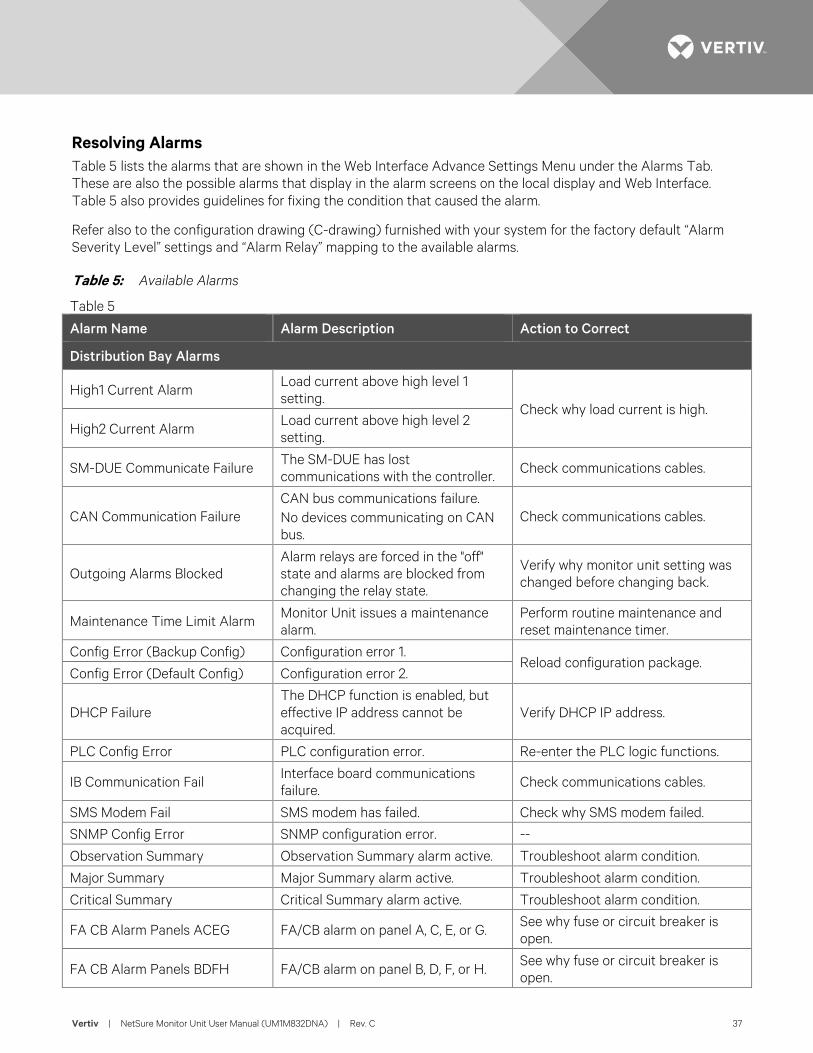
Resolving Alarms Table 5 lists the alarms that are shown in the Web Interface Advance Settings Menu under the Alarms Tab. These are also the possible alarms that display in the alarm screens on the local display and Web Interface. Table 5 also provides guidelines for fixing the condition that caused the alarm.
Refer also to the configuration drawing (C-drawing) furnished with your system for the factory default “Alarm Severity Level” settings and “Alarm Relay” mapping to the available alarms.
Table 5: Available Alarms
Table 5 Alarm Name Alarm Description Action to Correct
Distribution Bay Alarms
High1 Current Alarm Load current above high level 1 setting.
Check why load current is high. High2 Current Alarm
Load current above high level 2 setting.
SM-DUE Communicate Failure The SM-DUE has lost communications with the controller. Check communications cables.
CAN Communication Failure CAN bus communications failure. No devices communicating on CAN bus.
Check communications cables.
Outgoing Alarms Blocked Alarm relays are forced in the "off" state and alarms are blocked from changing the relay state.
Verify why monitor unit setting was changed before changing back.
Maintenance Time Limit Alarm Monitor Unit issues a maintenance alarm.
Perform routine maintenance and reset maintenance timer.
Config Error (Backup Config) Configuration error 1. Reload configuration package.
Config Error (Default Config) Configuration error 2.
DHCP Failure The DHCP function is enabled, but effective IP address cannot be acquired.
Verify DHCP IP address.
PLC Config Error PLC configuration error. Re-enter the PLC logic functions.
IB Communication Fail Interface board communications failure. Check communications cables.
SMS Modem Fail SMS modem has failed. Check why SMS modem failed.
SNMP Config Error SNMP configuration error. --
Observation Summary Observation Summary alarm active. Troubleshoot alarm condition.
Major Summary Major Summary alarm active. Troubleshoot alarm condition.
Critical Summary Critical Summary alarm active. Troubleshoot alarm condition.
FA CB Alarm Panels ACEG FA/CB alarm on panel A, C, E, or G. See why fuse or circuit breaker is open.
FA CB Alarm Panels BDFH FA/CB alarm on panel B, D, F, or H. See why fuse or circuit breaker is open.
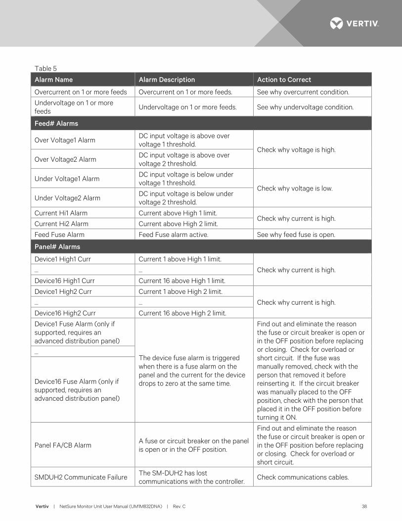
Vertiv | NetSure Monitor Unit User Manual (UM1M832DNA) | Rev. C 38
Table 5 Alarm Name Alarm Description Action to Correct
Overcurrent on 1 or more feeds Overcurrent on 1 or more feeds. See why overcurrent condition.
Undervoltage on 1 or more feeds Undervoltage on 1 or more feeds. See why undervoltage condition.
Feed# Alarms
Over Voltage1 Alarm DC input voltage is above over voltage 1 threshold.
Check why voltage is high. Over Voltage2 Alarm
DC input voltage is above over voltage 2 threshold.
Under Voltage1 Alarm DC input voltage is below under voltage 1 threshold.
Check why voltage is low. Under Voltage2 Alarm
DC input voltage is below under voltage 2 threshold.
Current Hi1 Alarm Current above High 1 limit. Check why current is high.
Current Hi2 Alarm Current above High 2 limit.
Feed Fuse Alarm Feed Fuse alarm active. See why feed fuse is open.
Panel# Alarms
Device1 High1 Curr Current 1 above High 1 limit.
Check why current is high. … …
Device16 High1 Curr Current 16 above High 1 limit.
Device1 High2 Curr Current 1 above High 2 limit.
Check why current is high. … …
Device16 High2 Curr Current 16 above High 2 limit.
Device1 Fuse Alarm (only if supported, requires an advanced distribution panel)
The device fuse alarm is triggered when there is a fuse alarm on the panel and the current for the device drops to zero at the same time.
Find out and eliminate the reason the fuse or circuit breaker is open or in the OFF position before replacing or closing. Check for overload or short circuit. If the fuse was manually removed, check with the person that removed it before reinserting it. If the circuit breaker was manually placed to the OFF position, check with the person that placed it in the OFF position before turning it ON.
…
Device16 Fuse Alarm (only if supported, requires an advanced distribution panel)
Panel FA/CB Alarm A fuse or circuit breaker on the panel is open or in the OFF position.
Find out and eliminate the reason the fuse or circuit breaker is open or in the OFF position before replacing or closing. Check for overload or short circuit.
SMDUH2 Communicate Failure The SM-DUH2 has lost communications with the controller.
Check communications cables.
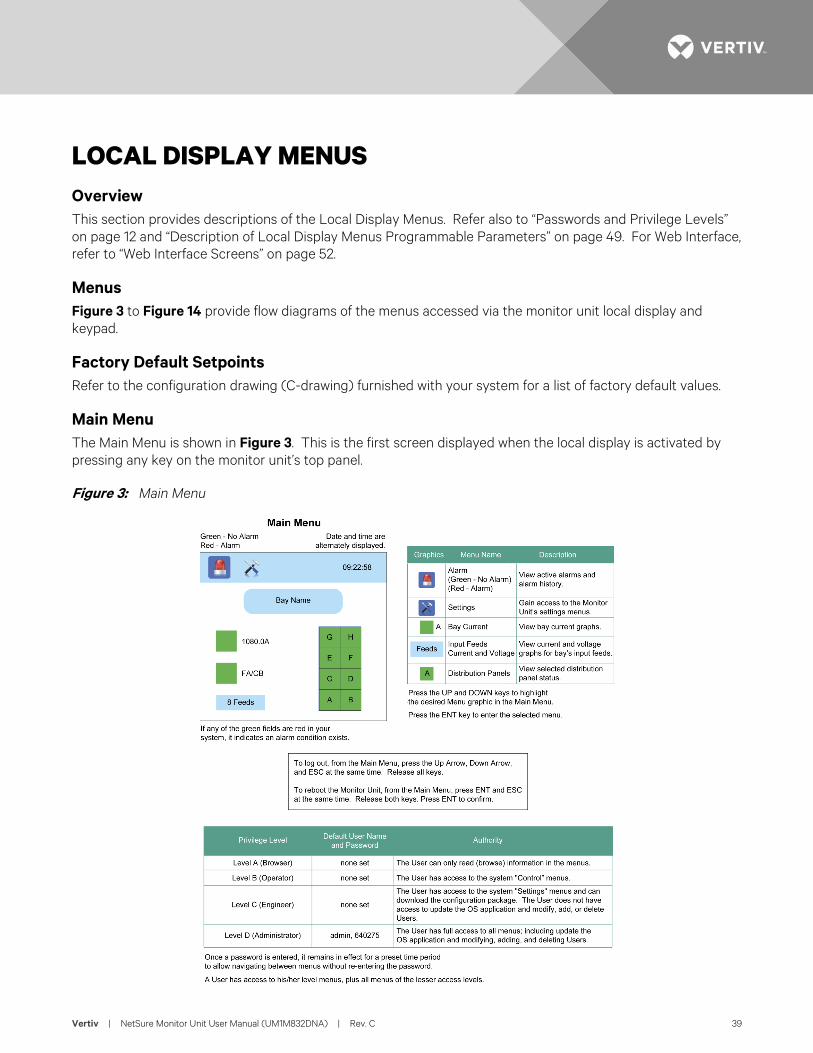
Vertiv | NetSure Monitor Unit User Manual (UM1M832DNA) | Rev. C 39
LOCAL DISPLAY MENUS Overview This section provides descriptions of the Local Display Menus. Refer also to “Passwords and Privilege Levels” on page 12 and “Description of Local Display Menus Programmable Parameters” on page 49. For Web Interface, refer to “Web Interface Screens” on page 52.
Menus Figure 3 to Figure 14 provide flow diagrams of the menus accessed via the monitor unit local display and keypad.
Factory Default Setpoints Refer to the configuration drawing (C-drawing) furnished with your system for a list of factory default values.
Main Menu The Main Menu is shown in Figure 3. This is the first screen displayed when the local display is activated by pressing any key on the monitor unit’s top panel.
Figure 3: Main Menu
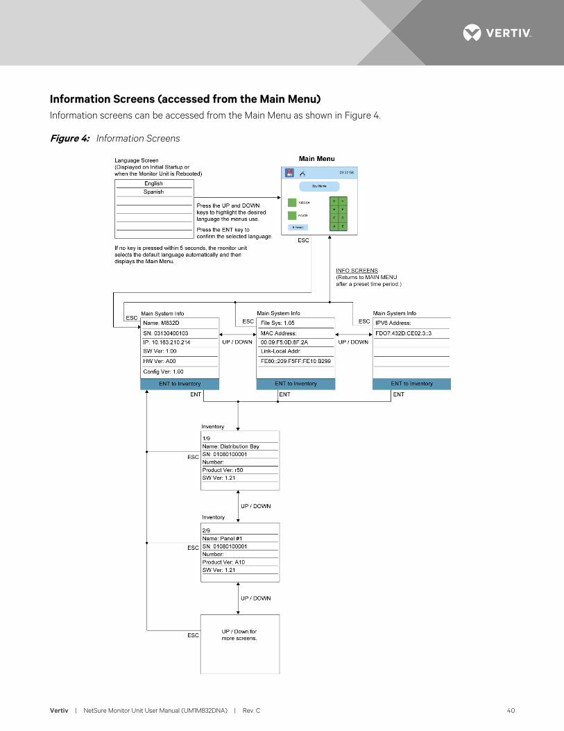
Vertiv | NetSure Monitor Unit User Manual (UM1M832DNA) | Rev. C 40
Information Screens (accessed from the Main Menu) Information screens can be accessed from the Main Menu as shown in Figure 4.
Figure 4: Information Screens
Vertiv | NetSure Monitor Unit User Manual (UM1M832DNA) | Rev. C 41
Alarm Menu The Alarm Menu can be accessed from the Main Menu as shown in Figure 5.
Figure 5: Alarm Menu
Vertiv | NetSure Monitor Unit User Manual (UM1M832DNA) | Rev. C 42
Settings Menu The Settings Menu can be accessed from the Main Menu as shown in Figure 6.
Figure 6: Settings Menu - Menu Selection
Vertiv | NetSure Monitor Unit User Manual (UM1M832DNA) | Rev. C 43
Figure 7: Settings Menu - Bay Menu
Figure 8: Settings Menu - Panel Menu
BayCapacity:2000A (10A to 6000A)High Curr Lmt1:80% (1% to 100%)High Curr Lmt2:90% (1% to 100%)Num of Panels:8 (2 / 4 / 6 / 8)Clear Datas:Clear (Clear)
ENT
ESCA To Change a Parameter:
Press the UP and DOWN keys tomove up and down list of parameters.
Press ENT to select the parameter.
Press the UP and DOWN keys tochange the parameter.
Press ENT to make the change.Press ESC to cancel the change.
The parameter values shown in ( ) are theadjustment range or acceptable values.
Bay >
To Change a Parameter:
Press the UP and DOWN keys tomove up and down list of parameters.
Press ENT to select the parameter.
Press the UP and DOWN keys tochange the parameter.
Press ENT to make the change.Press ESC to cancel the change.
The parameter values shown in ( ) are theadjustment range or acceptable values.
To Select a Sub-Menu:
Press the UP and DOWN keys tohighlight the desired sub-menu.
Press the ENT key to enter theselected sub-menu.
Note: Items marked with an “>” indicates there is a submenu.Press ENT to view the submenu.
PanelPanel A >Panel B >Panel C >Panel D >Panel E >Panel F >Panel G >Panel H >
ENT
ESC
ESC
B
Panel >
Panel APanel Exists:Used (Used / Not Used)Panel Type:Standard (Standard / Advanced)Num of Elements:16 (1 to 40)Feed ID:1 (1 to 8)Clear Datas:Clear (Clear)
Panel BPanel Exists:Used (Used / Not Used)Panel Type:Advanced (Standard / Advanced)Num of Elements:28 (1 to 40)Feed ID:1 (1 to 8)Clear Datas:Clear (Clear)Distribution Device >
A 01Device Exists:Used (Used / Not Used)Capacity:300A (10A to 2000A)High Curr Lmt1:85% (1% to 100%)High Curr Lmt2:95% (1% to 100%)Breaker Poles:3 (1 to 4)Clear Datas:Clear (Clear)
Distribution DeviceA 01 >A 02 >...A 39 >A 40 >
ENT
ENT
ENT
ENTESC
ESC
(when used with advanceddistribution panels)
Vertiv | NetSure Monitor Unit User Manual (UM1M832DNA) | Rev. C 44
Figure 9: Settings Menu - Feeds Menu
FeedsFeed 1 >Feed 2 >Feed 3 >Feed 4 >Feed 5 >Feed 6 >Feed 7 >Feed 8 >
ENT
ESCC
Feeds >
ENT
Feed 1Over Volt1:55.0V (40V to 60V)Over Volt2:58.0V (40V to 60V)Under Volt1:44.0V (40V to 60V)Under Volt2:43.0V (40V to 60V)Capacity:1000A (10A to 2000A)High Curr Lmt1:80% (1% to 100%)High Curr Lmt2:90% (1% to 100%)Shunt Voltage:25mV (10mV to 50mV)Shunt Current:800A (500A to 2000A)Clear Datas:Clear (Clear)
ESC
To Change a Parameter:
Press the UP and DOWN keys tomove up and down list of parameters.
Press ENT to select the parameter.
Press the UP and DOWN keys tochange the parameter.
Press ENT to make the change.Press ESC to cancel the change.
The parameter values shown in ( ) are theadjustment range or acceptable values.
To Select a Sub-Menu:
Press the UP and DOWN keys tohighlight the desired sub-menu.
Press the ENT key to enter theselected sub-menu.
Note: Items marked with an “>” indicates there is a submenu.Press ENT to view the submenu.
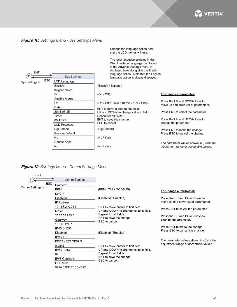
Vertiv | NetSure Monitor Unit User Manual (UM1M832DNA) | Rev. C 45
Figure 10: Settings Menu - Sys Settings Menu
Figure 11: Settings Menu - Comm Settings Menu
LCD Language:English (English / Espanol)Keypad Voice:On (On / Off)Audible Alarm:On (On / Off / 3 min / 10 min / 1 hr / 4 hrs)Date:2014-03-25Time:09:41:22LCD Rotation:Big Screen (Big Screen)Restore Default:No (No / Yes)Update App:No (No / Yes)
Sys SettingsDENT
ESC
ENT to move cursor to first field.UP and DOWN to change value in field.Repeat for all fields.ENT to save the change.ESC to cancel.
Sys Settings >
Change the language option herethat the LCD menus will use.
The local language selected in theWeb Interface Language Tab foundin the Advance Settings Menu isdisplayed here along side the Englishlanguage option. Note that the Englishlanguage option is always displayed.
To Change a Parameter:
Press the UP and DOWN keys tomove up and down list of parameters.
Press ENT to select the parameter.
Press the UP and DOWN keys tochange the parameter.
Press ENT to make the change.Press ESC to cancel the change.
The parameter values shown in ( ) are theadjustment range or acceptable values.
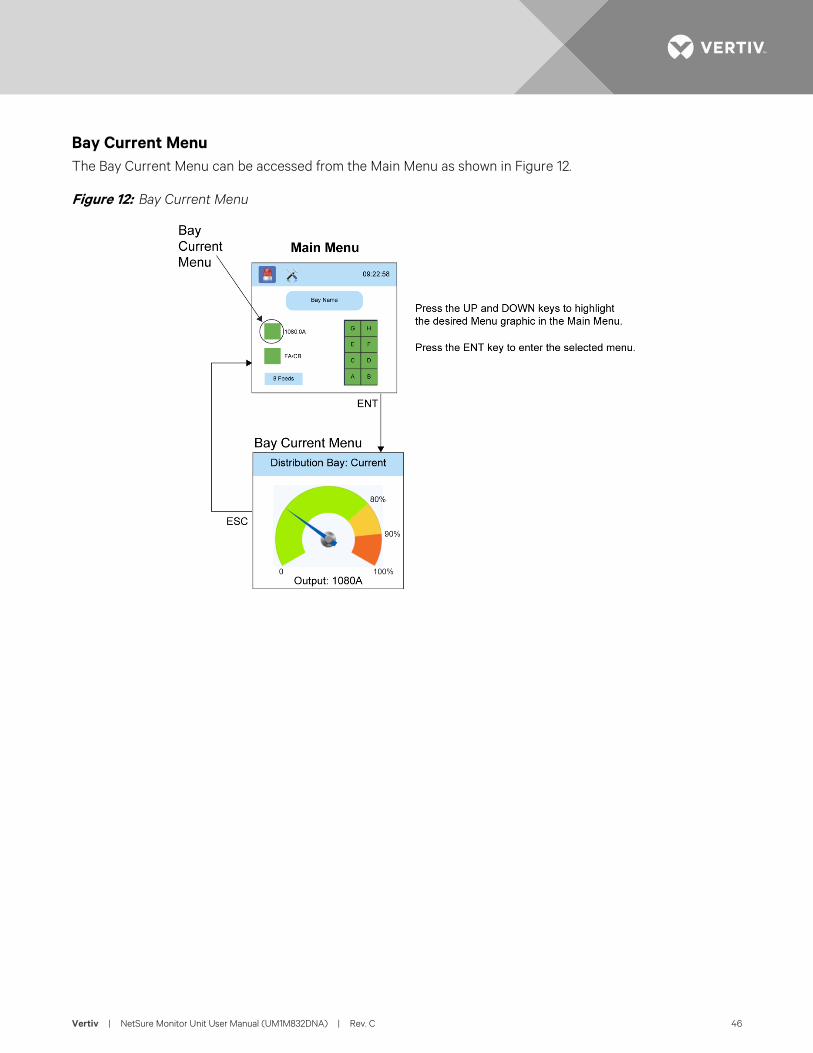
Vertiv | NetSure Monitor Unit User Manual (UM1M832DNA) | Rev. C 46
Bay Current Menu The Bay Current Menu can be accessed from the Main Menu as shown in Figure 12.
Figure 12: Bay Current Menu
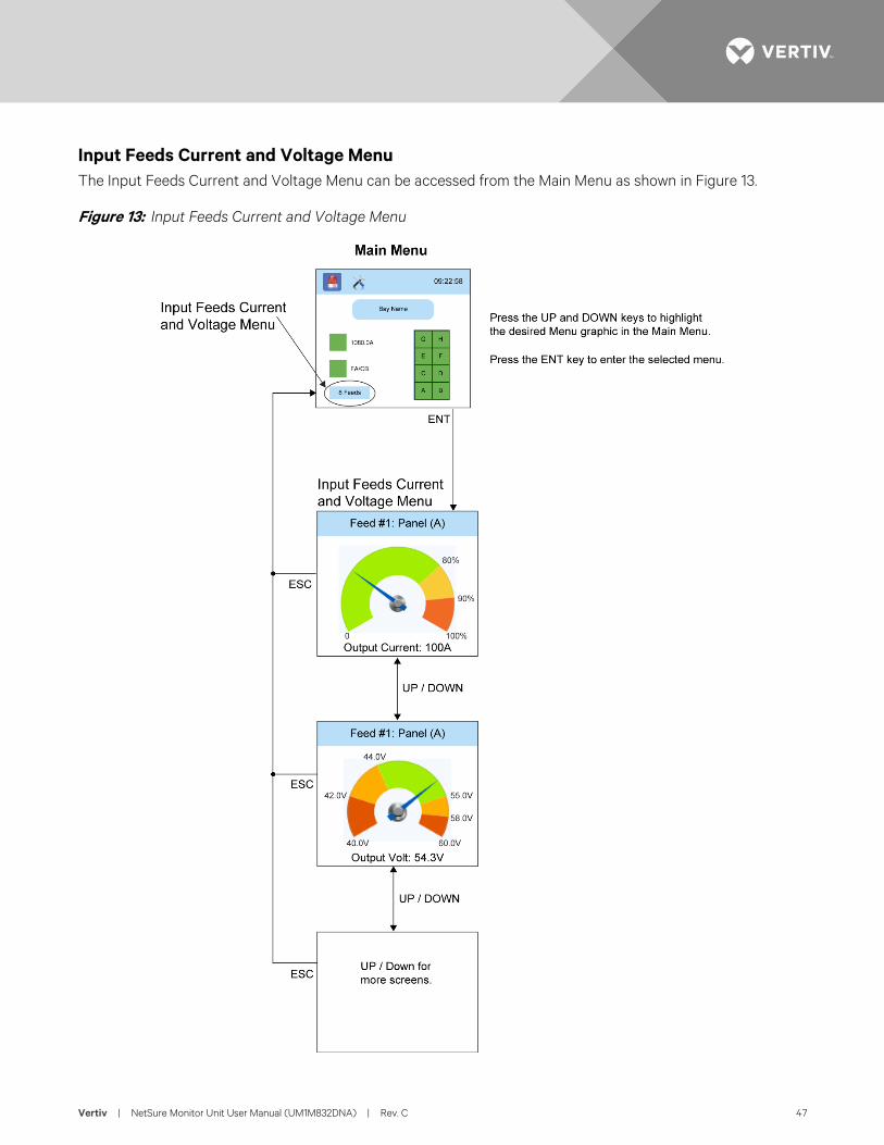
Vertiv | NetSure Monitor Unit User Manual (UM1M832DNA) | Rev. C 47
Input Feeds Current and Voltage Menu The Input Feeds Current and Voltage Menu can be accessed from the Main Menu as shown in Figure 13.
Figure 13: Input Feeds Current and Voltage Menu
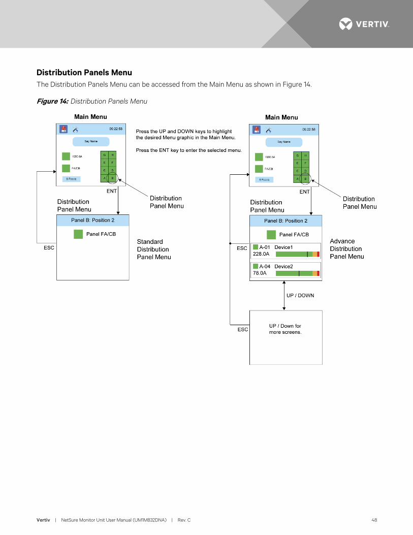
Vertiv | NetSure Monitor Unit User Manual (UM1M832DNA) | Rev. C 48
Distribution Panels Menu The Distribution Panels Menu can be accessed from the Main Menu as shown in Figure 14.
Figure 14: Distribution Panels Menu
Vertiv | NetSure Monitor Unit User Manual (UM1M832DNA) | Rev. C 49
DESCRIPTION OF LOCAL DISPLAY MENUS PROGRAMMABLE PARAMETERS The following are descriptions of the programmable parameters presented in the local display menus.
Settings Menu See Figure 6.
Bay Settings Sub-Menu • Capacity: Enter the bay’s capacity.
• High Curr Lmt1: Enter the bay’s high current 1 alarm setpoint. Enter the percentage value of the "capacity" for alarm.
• High Curr Lmt2: Enter the bay’s high current 2 alarm setpoint. Enter the percentage value of the "capacity" for alarm.
• Num of Panels: Enter the number of panels installed in the bay.
• Clear Datas: Clears the data stored for the bay.
Distribution Panel Settings Sub-Menu Select a distribution panel from the panels listed in the menu.
• Panel Exists: Select “Used” or “Not Used”.
• Panel Type: Select “Standard” or “Advanced”.
• Num of Elements: Enter the number of distribution devices that are installed in the distribution panel.
• Feed ID: Assigned which input feed is connected to the distribution panel. Note: Program the "Feed ID" for panels starting from panels at the top, to the panels at the bottom.
• Clear Datas: Clears the data stored for the panel.
• Distribution Device (Advanced Panels Only): Select a distribution device from the distribution devices listed in the menu.
- Device Exists: Select “Used” or “Not Used”. - Capacity: Enter the distribution device’s capacity. - High Curr Lmt1: Enter the distribution device’s high current 1 alarm setpoint. Enter the percentage
value of the "capacity" for alarm. - High Curr Lmt2: Enter the distribution device’s high current 2 alarm setpoint. Enter the
percentage value of the "capacity" for alarm. - Breaker Poles: Enter the number of poles the distribution device has. - Clear Datas: Clears the data stored for the distribution device.
Vertiv | NetSure Monitor Unit User Manual (UM1M832DNA) | Rev. C 50
Feeds Settings Sub-Menu Select an input feed from the feeds listed in the menu.
• Over Volt1: Enter the feed’s over voltage 1 alarm setpoint.
• Over Volt2: Enter the feed’s over voltage 2 alarm setpoint.
• Under Volt1: Enter the feed’s under voltage 1 alarm setpoint.
• Under Volt2: Enter the feed’s under voltage 2 alarm setpoint.
• Capacity: Enter the feed’s capacity.
• High Curr Lmt1: Enter the feed’s high current 1 alarm setpoint. Enter the percentage value of the "capacity" for alarm.
• High Curr Lmt2: Enter the feed’s high current 2 alarm setpoint. Enter the percentage value of the "capacity" for alarm.
• Shunt Voltage: Enter the feed’s shunt voltage rating.
• Shunt Current: Enter the feed’s shunt current rating.
• Clear Datas: Clears the data stored for this feed.
Sys Settings Sub-Menu • LCD Language: Select the language the menus are displayed in.
• Keypad Voice: Sets the keypad sound on or off.
• Audible Alarm
- Off: Disables the audible alarm. - On: When a new alarm occurs, the audible alarm sounds. Press any key to silence the audible alarm. - 3 min / 10 min / 1 hr / 4 hrs: When a new alarm occurs, the audible alarm sounds. The audible
alarm automatically silences after the selected time period.
• Date: Sets the date. Refer to “Changing the Date and Time” on page 23 for a procedure to change the date.
• Time: Sets the time. Refer to “Changing the Date and Time” on page 23 for a procedure to change the time.
• LCD Rotation: not applicable.
- Big Screen: Only setting available.
• Restore Default: Restores the monitor unit’s default settings.
• Update App: Updates the monitor unit’s application.
Comm Settings Sub-Menu • Protocol: Select "EEM", "TL1",or "Modbus" as the protocol.
Vertiv | NetSure Monitor Unit User Manual (UM1M832DNA) | Rev. C 51
• DHCP: The DHCP function allows the monitor unit to acquire an IP address automatically. This function can only be enabled or disabled via the local display and keypad. If this function is enabled and the acquisition of an IP address fails, an alarm is generated. If the acquisition of an IP address is successful, you need to record the IP address automatically acquired by the monitor unit to access the monitor unit via the Web Interface. This IP address is displayed in the IP Address field below the DHCP setting in the local display menu (Main Menu / Settings Icon / Comm Settings).
• IP Address: Sets the monitor unit's IPv4 address. Enter the address in the format nnn.nnn.nnn.nnn, where 0 ≤ nnn ≤ 255. The address must be a valid address and must not be 255.255.255.255.
• Mask: Sets the monitor unit's IPv4 network netmask. Enter the address in the format nnn.nnn.nnn.nnn, where 0 ≤ nnn ≤ 255.
• Gateway: Sets the monitor unit's IPv4 gateway address. Enter the address in the format nnn.nnn.nnn.nnn, where 0 ≤ nnn ≤ 255. This is the address of the gateway of the network on which the monitor unit resides. The address must be a valid address and must not be 255.255.255.255.
• IPV6 DHCP: The IPV6 DHCP function allows the monitor unit to acquire an IP address automatically. This function can only be enabled or disabled via the local display and keypad. If this function is enabled and the acquisition of an IP address fails, an alarm is generated. If the acquisition of an IP address is successful, you need to record the IP address automatically acquired by the monitor unit to access the monitor unit via the Web Interface. This IP address is displayed in the IP Address field below the DHCP setting in the local display menu (Main Menu / Settings Icon / Comm Settings).
• IPV6 IP: Sets the monitor unit's IPv6 address. Enter the address in the format nnnn:nnnn:nnnn:nnnn:nnnn:nnnn:nnnn:nnnn, nnnn must follow IPv6 address rules.
• IPV6 Prefix: Sets the monitor unit's IPv6 prefix.
• IPV6 Gateway: Sets the monitor unit's IPv6 gateway address. Enter the address in the format nnnn:nnnn:nnnn:nnnn:nnnn:nnnn:nnnn:nnnn, nnnn must follow IPv6 address rules.
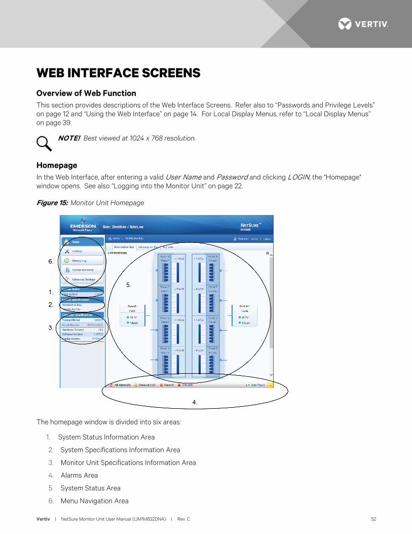
Vertiv | NetSure Monitor Unit User Manual (UM1M832DNA) | Rev. C 52
WEB INTERFACE SCREENS Overview of Web Function This section provides descriptions of the Web Interface Screens. Refer also to “Passwords and Privilege Levels” on page 12 and “Using the Web Interface” on page 14. For Local Display Menus, refer to “Local Display Menus” on page 39.
NOTE! Best viewed at 1024 x 768 resolution.
Homepage In the Web Interface, after entering a valid User Name and Password and clicking LOGIN, the "Homepage" window opens. See also “Logging into the Monitor Unit” on page 22.
Figure 15: Monitor Unit Homepage
The homepage window is divided into six areas:
1. System Status Information Area
2. System Specifications Information Area
3. Monitor Unit Specifications Information Area
4. Alarms Area
5. System Status Area
6. Menu Navigation Area
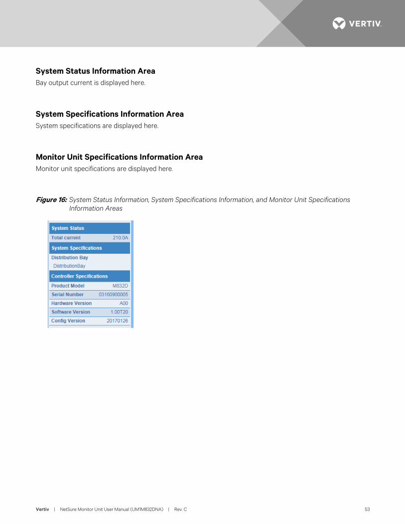
Vertiv | NetSure Monitor Unit User Manual (UM1M832DNA) | Rev. C 53
System Status Information Area Bay output current is displayed here.
System Specifications Information Area System specifications are displayed here.
Monitor Unit Specifications Information Area Monitor unit specifications are displayed here.
Figure 16: System Status Information, System Specifications Information, and Monitor Unit Specifications Information Areas
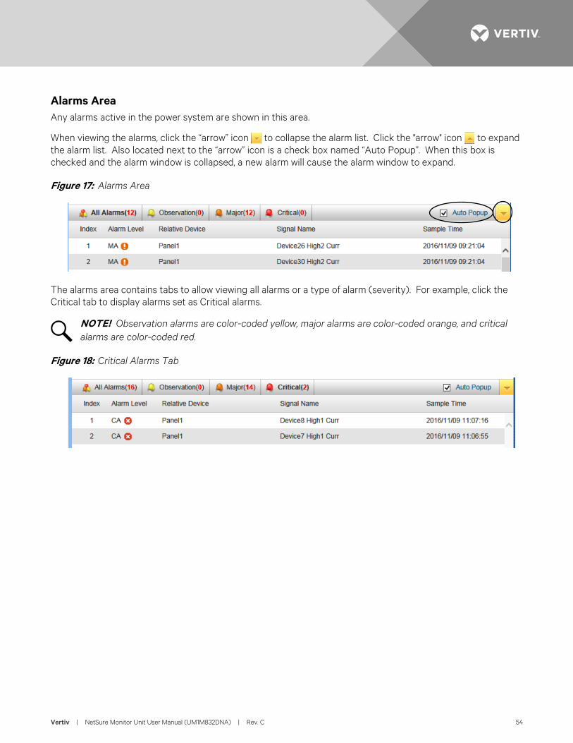
Vertiv | NetSure Monitor Unit User Manual (UM1M832DNA) | Rev. C 54
Alarms Area Any alarms active in the power system are shown in this area.
When viewing the alarms, click the “arrow” icon to collapse the alarm list. Click the "arrow" icon to expand the alarm list. Also located next to the “arrow” icon is a check box named “Auto Popup”. When this box is checked and the alarm window is collapsed, a new alarm will cause the alarm window to expand.
Figure 17: Alarms Area
The alarms area contains tabs to allow viewing all alarms or a type of alarm (severity). For example, click the Critical tab to display alarms set as Critical alarms.
NOTE! Observation alarms are color-coded yellow, major alarms are color-coded orange, and critical alarms are color-coded red.
Figure 18: Critical Alarms Tab
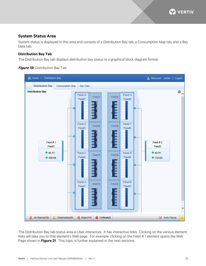
Vertiv | NetSure Monitor Unit User Manual (UM1M832DNA) | Rev. C 55
System Status Area System status is displayed in this area and consists of a Distribution Bay tab, a Consumption Map tab, and a Bay Data tab.
Distribution Bay Tab The Distribution Bay tab displays distribution bay status in a graphical block diagram format.
Figure 19: Distribution Bay Tab
The Distribution Bay tab status area is User interactive. It has interactive links. Clicking on the various element links will take you to that element’s Web page. For example, clicking on the Feed # 1 element opens the Web Page shown in Figure 21. This topic is further explained in the next sections.
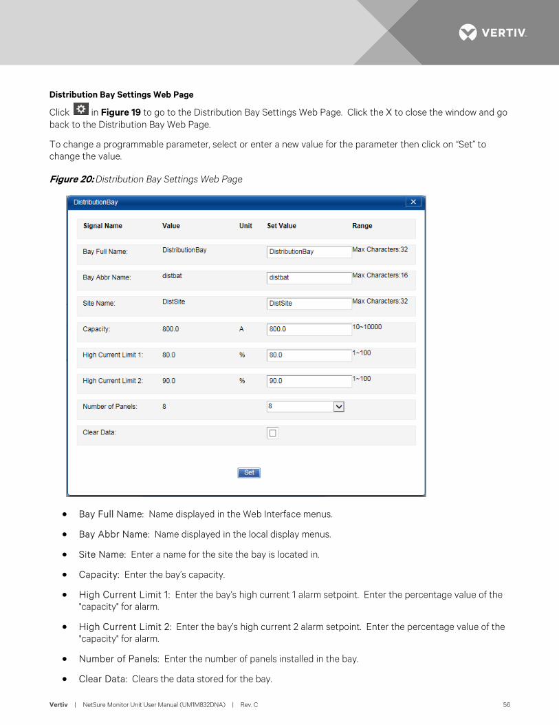
Vertiv | NetSure Monitor Unit User Manual (UM1M832DNA) | Rev. C 56
Distribution Bay Settings Web Page
Click in Figure 19 to go to the Distribution Bay Settings Web Page. Click the X to close the window and go back to the Distribution Bay Web Page.
To change a programmable parameter, select or enter a new value for the parameter then click on “Set” to change the value.
Figure 20: Distribution Bay Settings Web Page
• Bay Full Name: Name displayed in the Web Interface menus.
• Bay Abbr Name: Name displayed in the local display menus.
• Site Name: Enter a name for the site the bay is located in.
• Capacity: Enter the bay’s capacity.
• High Current Limit 1: Enter the bay’s high current 1 alarm setpoint. Enter the percentage value of the "capacity" for alarm.
• High Current Limit 2: Enter the bay’s high current 2 alarm setpoint. Enter the percentage value of the "capacity" for alarm.
• Number of Panels: Enter the number of panels installed in the bay.
• Clear Data: Clears the data stored for the bay.
Vertiv | NetSure Monitor Unit User Manual (UM1M832DNA) | Rev. C 57
Feed Web Page
Click on the Feed 1 element in Figure 19 opens the Web Page shown in Figure 21.
The Feed Web Page allows you to view feed data and set feed parameters.
The peak values (peak for 24 hours, etc.) are captured as soon as they happen. The total power for 24/week/month are not recorded until the period has passed (meaning the total for 24 hours isn't recorded until 24 hours have passed, etc.).
Figure 21: Feed Web Page
Clicking here opens the following Web page.
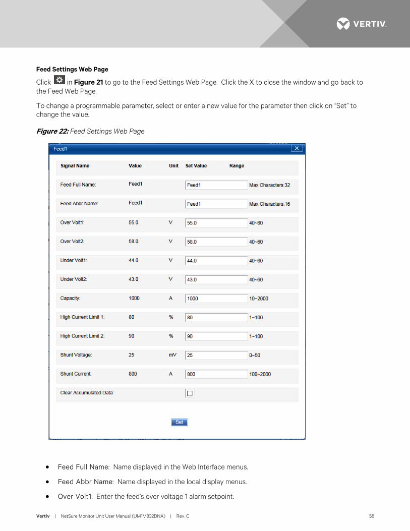
Vertiv | NetSure Monitor Unit User Manual (UM1M832DNA) | Rev. C 58
Feed Settings Web Page
Click in Figure 21 to go to the Feed Settings Web Page. Click the X to close the window and go back to the Feed Web Page.
To change a programmable parameter, select or enter a new value for the parameter then click on “Set” to change the value.
Figure 22: Feed Settings Web Page
• Feed Full Name: Name displayed in the Web Interface menus.
• Feed Abbr Name: Name displayed in the local display menus.
• Over Volt1: Enter the feed’s over voltage 1 alarm setpoint.
Vertiv | NetSure Monitor Unit User Manual (UM1M832DNA) | Rev. C 59
• Over Volt2: Enter the feed’s over voltage 2 alarm setpoint.
• Under Volt1: Enter the feed’s under voltage 1 alarm setpoint.
• Under Volt2: Enter the feed’s under voltage 2 alarm setpoint.
• Capacity: Enter the feed’s capacity.
• High Current Limit 1: Enter the feed’s high current 1 alarm setpoint. Enter the percentage value of the "capacity" for alarm.
• High Current Limit 2: Enter the feed’s high current 2 alarm setpoint. Enter the percentage value of the "capacity" for alarm.
• Shunt Voltage: Enter the feed’s shunt voltage rating.
• Shunt Current: Enter the feed’s shunt current rating.
• Clear Accumulated Data: Clears the data stored for this feed.
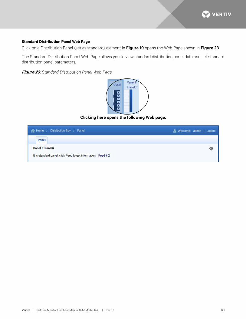
Vertiv | NetSure Monitor Unit User Manual (UM1M832DNA) | Rev. C 60
Standard Distribution Panel Web Page
Click on a Distribution Panel (set as standard) element in Figure 19 opens the Web Page shown in Figure 23.
The Standard Distribution Panel Web Page allows you to view standard distribution panel data and set standard distribution panel parameters.
Figure 23: Standard Distribution Panel Web Page
Clicking here opens the following Web page.
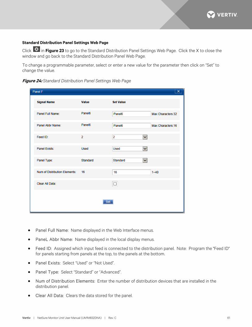
Vertiv | NetSure Monitor Unit User Manual (UM1M832DNA) | Rev. C 61
Standard Distribution Panel Settings Web Page
Click in Figure 23 to go to the Standard Distribution Panel Settings Web Page. Click the X to close the window and go back to the Standard Distribution Panel Web Page.
To change a programmable parameter, select or enter a new value for the parameter then click on “Set” to change the value.
Figure 24: Standard Distribution Panel Settings Web Page
• Panel Full Name: Name displayed in the Web Interface menus.
• PaneL Abbr Name: Name displayed in the local display menus.
• Feed ID: Assigned which input feed is connected to the distribution panel. Note: Program the "Feed ID" for panels starting from panels at the top, to the panels at the bottom.
• Panel Exists: Select “Used” or “Not Used”.
• Panel Type: Select “Standard” or “Advanced”.
• Num of Distribution Elements: Enter the number of distribution devices that are installed in the distribution panel.
• Clear All Data: Clears the data stored for the panel.
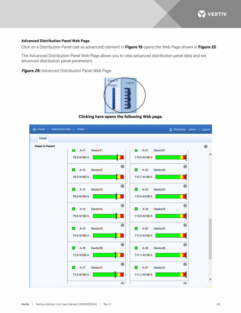
Vertiv | NetSure Monitor Unit User Manual (UM1M832DNA) | Rev. C 62
Advanced Distribution Panel Web Page
Click on a Distribution Panel (set as advanced) element in Figure 19 opens the Web Page shown in Figure 25.
The Advanced Distribution Panel Web Page allows you to view advanced distribution panel data and set advanced distribution panel parameters.
Figure 25: Advanced Distribution Panel Web Page
Clicking here opens the following Web page.
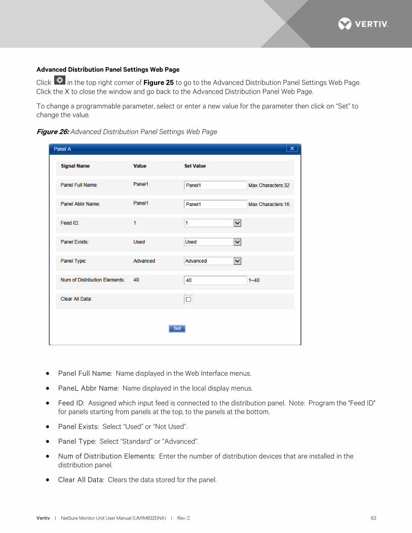
Vertiv | NetSure Monitor Unit User Manual (UM1M832DNA) | Rev. C 63
Advanced Distribution Panel Settings Web Page
Click in the top right corner of Figure 25 to go to the Advanced Distribution Panel Settings Web Page. Click the X to close the window and go back to the Advanced Distribution Panel Web Page.
To change a programmable parameter, select or enter a new value for the parameter then click on “Set” to change the value.
Figure 26: Advanced Distribution Panel Settings Web Page
• Panel Full Name: Name displayed in the Web Interface menus.
• PaneL Abbr Name: Name displayed in the local display menus.
• Feed ID: Assigned which input feed is connected to the distribution panel. Note: Program the "Feed ID" for panels starting from panels at the top, to the panels at the bottom.
• Panel Exists: Select “Used” or “Not Used”.
• Panel Type: Select “Standard” or “Advanced”.
• Num of Distribution Elements: Enter the number of distribution devices that are installed in the distribution panel.
• Clear All Data: Clears the data stored for the panel.
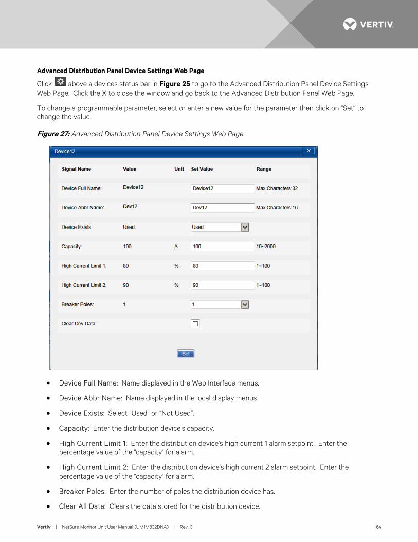
Vertiv | NetSure Monitor Unit User Manual (UM1M832DNA) | Rev. C 64
Advanced Distribution Panel Device Settings Web Page
Click above a devices status bar in Figure 25 to go to the Advanced Distribution Panel Device Settings Web Page. Click the X to close the window and go back to the Advanced Distribution Panel Web Page.
To change a programmable parameter, select or enter a new value for the parameter then click on “Set” to change the value.
Figure 27: Advanced Distribution Panel Device Settings Web Page
• Device Full Name: Name displayed in the Web Interface menus.
• Device Abbr Name: Name displayed in the local display menus.
• Device Exists: Select “Used” or “Not Used”.
• Capacity: Enter the distribution device’s capacity.
• High Current Limit 1: Enter the distribution device’s high current 1 alarm setpoint. Enter the percentage value of the "capacity" for alarm.
• High Current Limit 2: Enter the distribution device’s high current 2 alarm setpoint. Enter the percentage value of the "capacity" for alarm.
• Breaker Poles: Enter the number of poles the distribution device has.
• Clear All Data: Clears the data stored for the distribution device.
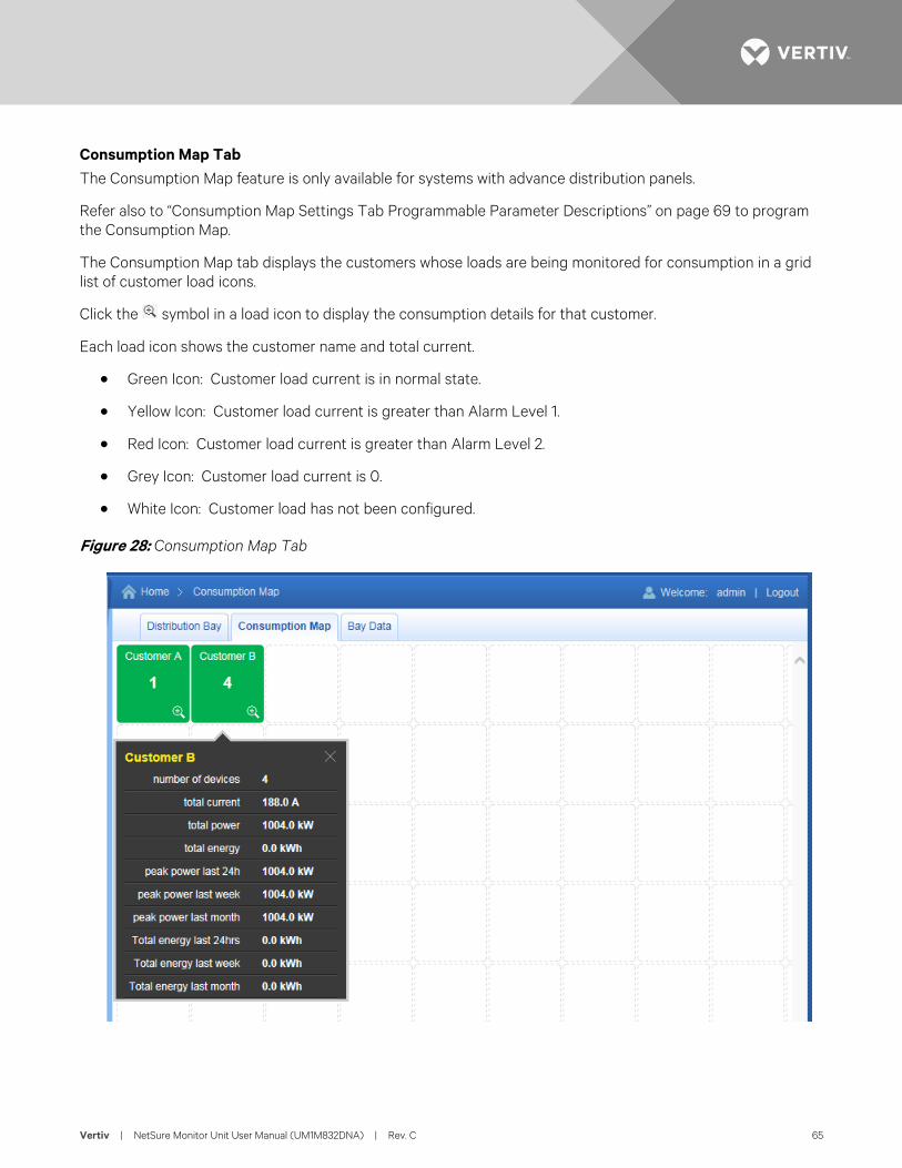
Vertiv | NetSure Monitor Unit User Manual (UM1M832DNA) | Rev. C 65
Consumption Map Tab The Consumption Map feature is only available for systems with advance distribution panels.
Refer also to “Consumption Map Settings Tab Programmable Parameter Descriptions” on page 69 to program the Consumption Map.
The Consumption Map tab displays the customers whose loads are being monitored for consumption in a grid list of customer load icons.
Click the symbol in a load icon to display the consumption details for that customer.
Each load icon shows the customer name and total current.
• Green Icon: Customer load current is in normal state.
• Yellow Icon: Customer load current is greater than Alarm Level 1.
• Red Icon: Customer load current is greater than Alarm Level 2.
• Grey Icon: Customer load current is 0.
• White Icon: Customer load has not been configured.
Figure 28: Consumption Map Tab
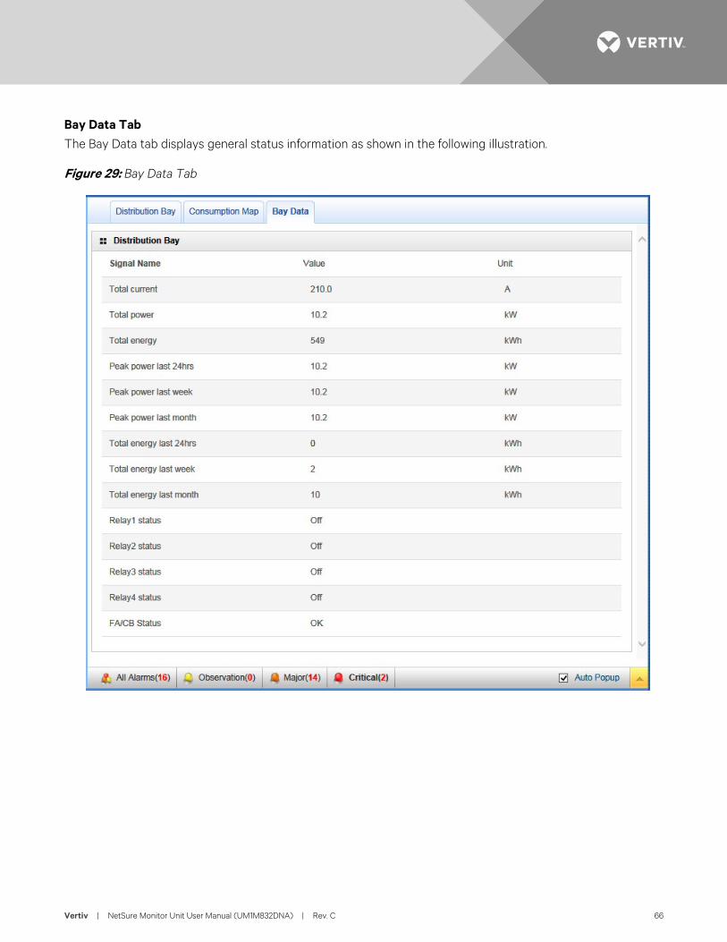
Vertiv | NetSure Monitor Unit User Manual (UM1M832DNA) | Rev. C 66
Bay Data Tab The Bay Data tab displays general status information as shown in the following illustration.
Figure 29: Bay Data Tab
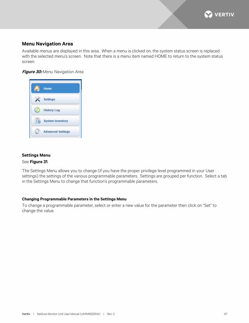
Vertiv | NetSure Monitor Unit User Manual (UM1M832DNA) | Rev. C 67
Menu Navigation Area Available menus are displayed in this area. When a menu is clicked on, the system status screen is replaced with the selected menu’s screen. Note that there is a menu item named HOME to return to the system status screen.
Figure 30: Menu Navigation Area
Settings Menu See Figure 31.
The Settings Menu allows you to change (if you have the proper privilege level programmed in your User settings) the settings of the various programmable parameters. Settings are grouped per function. Select a tab in the Settings Menu to change that function’s programmable parameters.
Changing Programmable Parameters in the Settings Menu
To change a programmable parameter, select or enter a new value for the parameter then click on “Set” to change the value.
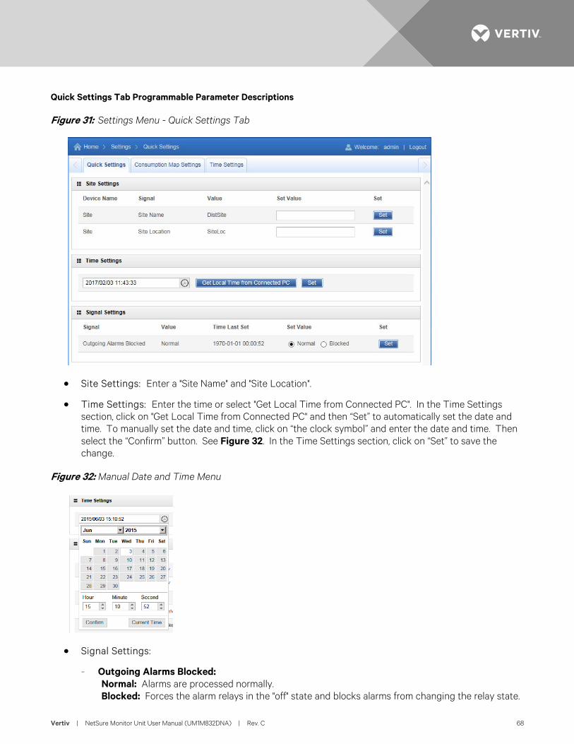
Vertiv | NetSure Monitor Unit User Manual (UM1M832DNA) | Rev. C 68
Quick Settings Tab Programmable Parameter Descriptions
Figure 31: Settings Menu - Quick Settings Tab
• Site Settings: Enter a "Site Name" and "Site Location".
• Time Settings: Enter the time or select "Get Local Time from Connected PC". In the Time Settings section, click on "Get Local Time from Connected PC" and then “Set” to automatically set the date and time. To manually set the date and time, click on “the clock symbol” and enter the date and time. Then select the “Confirm” button. See Figure 32. In the Time Settings section, click on “Set” to save the change.
Figure 32: Manual Date and Time Menu
• Signal Settings:
- Outgoing Alarms Blocked: Normal: Alarms are processed normally. Blocked: Forces the alarm relays in the "off" state and blocks alarms from changing the relay state.
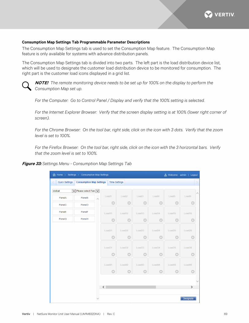
Vertiv | NetSure Monitor Unit User Manual (UM1M832DNA) | Rev. C 69
Consumption Map Settings Tab Programmable Parameter Descriptions
The Consumption Map Settings tab is used to set the Consumption Map feature. The Consumption Map feature is only available for systems with advance distribution panels.
The Consumption Map Settings tab is divided into two parts. The left part is the load distribution device list, which will be used to designate the customer load distribution device to be monitored for consumption. The right part is the customer load icons displayed in a grid list.
NOTE! The remote monitoring device needs to be set up for 100% on the display to perform the Consumption Map set up. For the Computer: Go to Control Panel / Display and verify that the 100% setting is selected. For the Internet Explorer Browser: Verify that the screen display setting is at 100% (lower right corner of screen). For the Chrome Browser: On the tool bar, right side, click on the icon with 3 dots. Verify that the zoom level is set to 100%. For the Firefox Browser: On the tool bar, right side, click on the icon with the 3 horizontal bars. Verify that the zoom level is set to 100%.
Figure 33: Settings Menu - Consumption Map Settings Tab
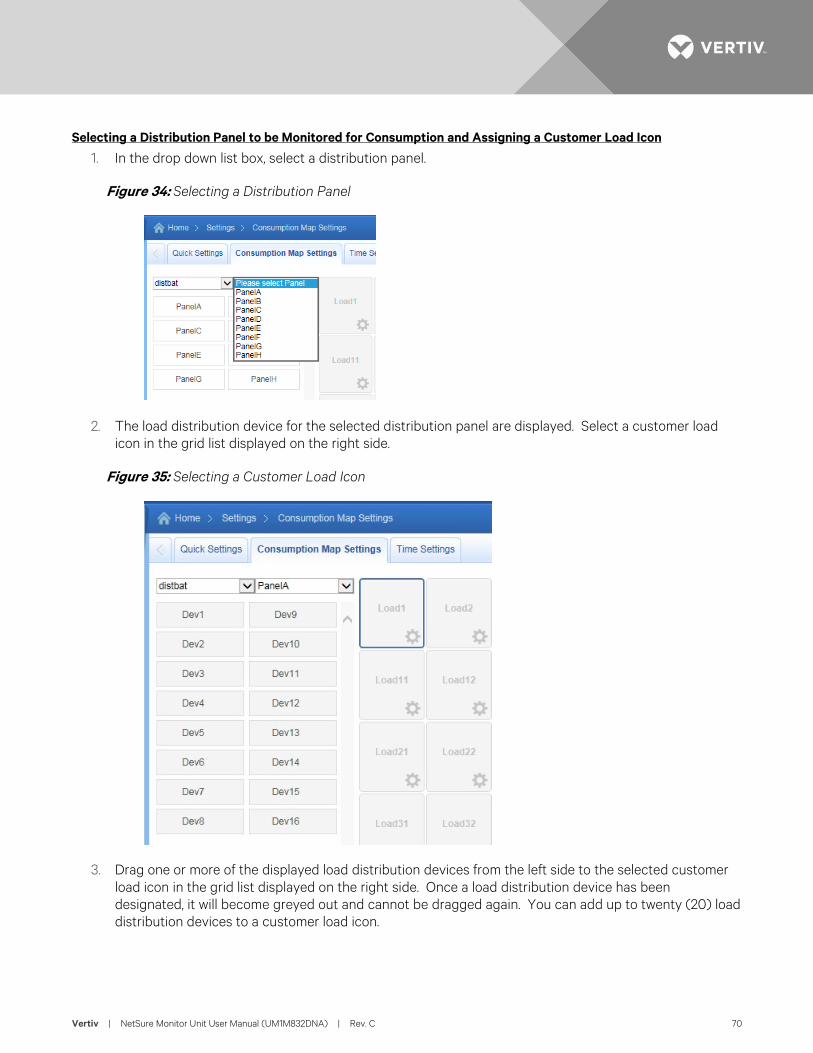
Vertiv | NetSure Monitor Unit User Manual (UM1M832DNA) | Rev. C 70
Selecting a Distribution Panel to be Monitored for Consumption and Assigning a Customer Load Icon
1. In the drop down list box, select a distribution panel.
Figure 34: Selecting a Distribution Panel
2. The load distribution device for the selected distribution panel are displayed. Select a customer load icon in the grid list displayed on the right side.
Figure 35: Selecting a Customer Load Icon
3. Drag one or more of the displayed load distribution devices from the left side to the selected customer load icon in the grid list displayed on the right side. Once a load distribution device has been designated, it will become greyed out and cannot be dragged again. You can add up to twenty (20) load distribution devices to a customer load icon.
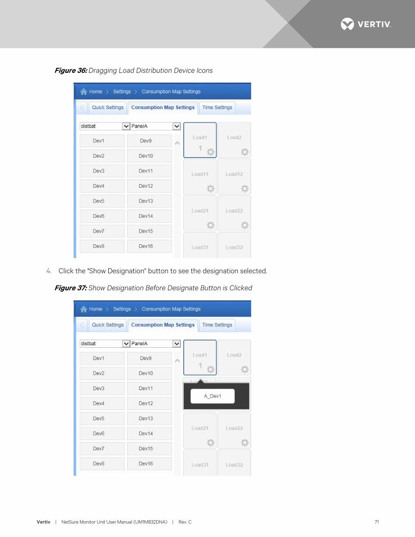
Vertiv | NetSure Monitor Unit User Manual (UM1M832DNA) | Rev. C 71
Figure 36: Dragging Load Distribution Device Icons
4. Click the "Show Designation" button to see the designation selected.
Figure 37: Show Designation Before Designate Button is Clicked
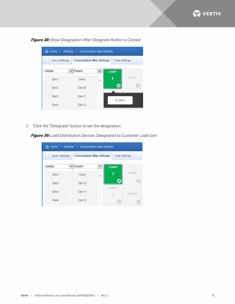
Vertiv | NetSure Monitor Unit User Manual (UM1M832DNA) | Rev. C 72
Figure 38: Show Designation After Designate Button is Clicked
5. Click the "Designate" button to set the designation.
Figure 39: Load Distribution Devices Designated to Customer Load Icon
Vertiv | NetSure Monitor Unit User Manual (UM1M832DNA) | Rev. C 73
Setting the Customer Load Icons Parameters
1. Click the symbol next to the customer load icon to be set. The following window opens. Enter the customer load icon parameters and click Set.
Figure 40: Setting the Customer Icons Parameters
• Name: The name of the customer.
• Capacity: Enter a value for the customer load device current rating.
• Alarm Level 1: If the customer load(s) exceeds the percent of the total device current rating entered for Alarm Level 1, the icon representing the customer load turns yellow, which indicates an observation alarm.
• Alarm Level 2: If the customer load(s) exceeds the percent of the total device current rating entered for Alarm Level 2, the icon representing the customer load turns red, which indicates an major alarm.
Vertiv | NetSure Monitor Unit User Manual (UM1M832DNA) | Rev. C 74
Time Settings Tab Programmable Parameter Descriptions
See also “Changing the Date and Time” on page 23.
Figure 41: Settings Menu - Time Settings Tab
• Specify Time
- Get Local Time from Connected PC: Allows you to automatically set the time. When selected, the monitor unit will get the same time as the connected PC.
- Date & Time: Allows you to manually set the date and time. To manually set the date and time, click on “the clock symbol” and enter the date and time. Then select the “Confirm” button. See Figure 32.
• Local Zone (for synchronization with time servers): When selected, the monitor unit will get the local zone automatically or you can enter the zone.
• Get time automatically from the following servers.
- When selected, the monitor unit will get the time from the selected time server. The monitor unit will also adjust the time per the "Local Zone" setting.
Vertiv | NetSure Monitor Unit User Manual (UM1M832DNA) | Rev. C 75
History Log Menu The History Log Menu allows you to view and save the various logs available in the monitor unit.
Alarm History Log Tab
Alarm log contains a history of alarms. Alarms are added to the alarm log when the alarm condition no longer exists.
Select Device and Time
Select the "Device" to query from the drop-down list box. Select the "from" and "to" time.
Figure 42: Alarm History Log Device and Time Selection
Vertiv | NetSure Monitor Unit User Manual (UM1M832DNA) | Rev. C 76
Query Alarm History Log
Click “Query” to query for alarms within selected time slot. The Web page displays the last 500 entries.
Figure 43:Alarm History Log Query
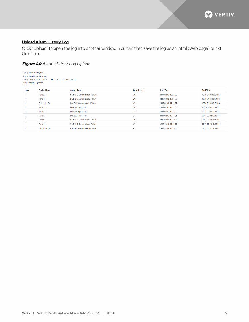
Vertiv | NetSure Monitor Unit User Manual (UM1M832DNA) | Rev. C 77
Upload Alarm History Log
Click “Upload” to open the log into another window. You can then save the log as an .html (Web page) or .txt (text) file.
Figure 44: Alarm History Log Upload
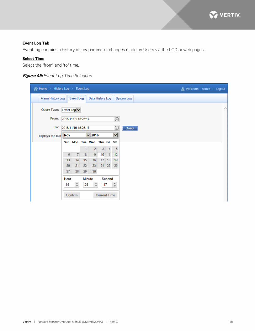
Vertiv | NetSure Monitor Unit User Manual (UM1M832DNA) | Rev. C 78
Event Log Tab
Event log contains a history of key parameter changes made by Users via the LCD or web pages.
Select Time
Select the "from" and "to" time.
Figure 45: Event Log Time Selection
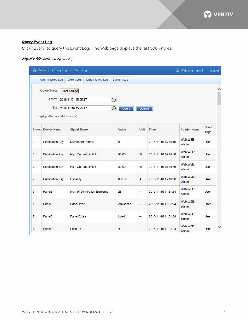
Vertiv | NetSure Monitor Unit User Manual (UM1M832DNA) | Rev. C 79
Query Event Log
Click “Query” to query the Event Log. The Web page displays the last 500 entries.
Figure 46: Event Log Query
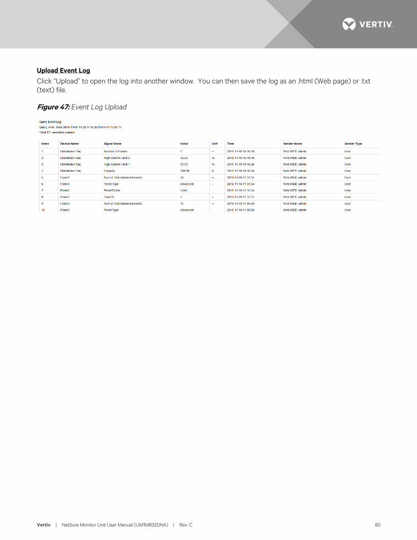
Vertiv | NetSure Monitor Unit User Manual (UM1M832DNA) | Rev. C 80
Upload Event Log
Click “Upload” to open the log into another window. You can then save the log as an .html (Web page) or .txt (text) file.
Figure 47: Event Log Upload
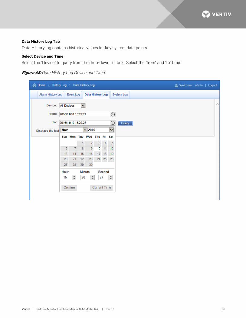
Vertiv | NetSure Monitor Unit User Manual (UM1M832DNA) | Rev. C 81
Data History Log Tab
Data History log contains historical values for key system data points.
Select Device and Time
Select the "Device" to query from the drop-down list box. Select the "from" and "to" time.
Figure 48: Data History Log Device and Time
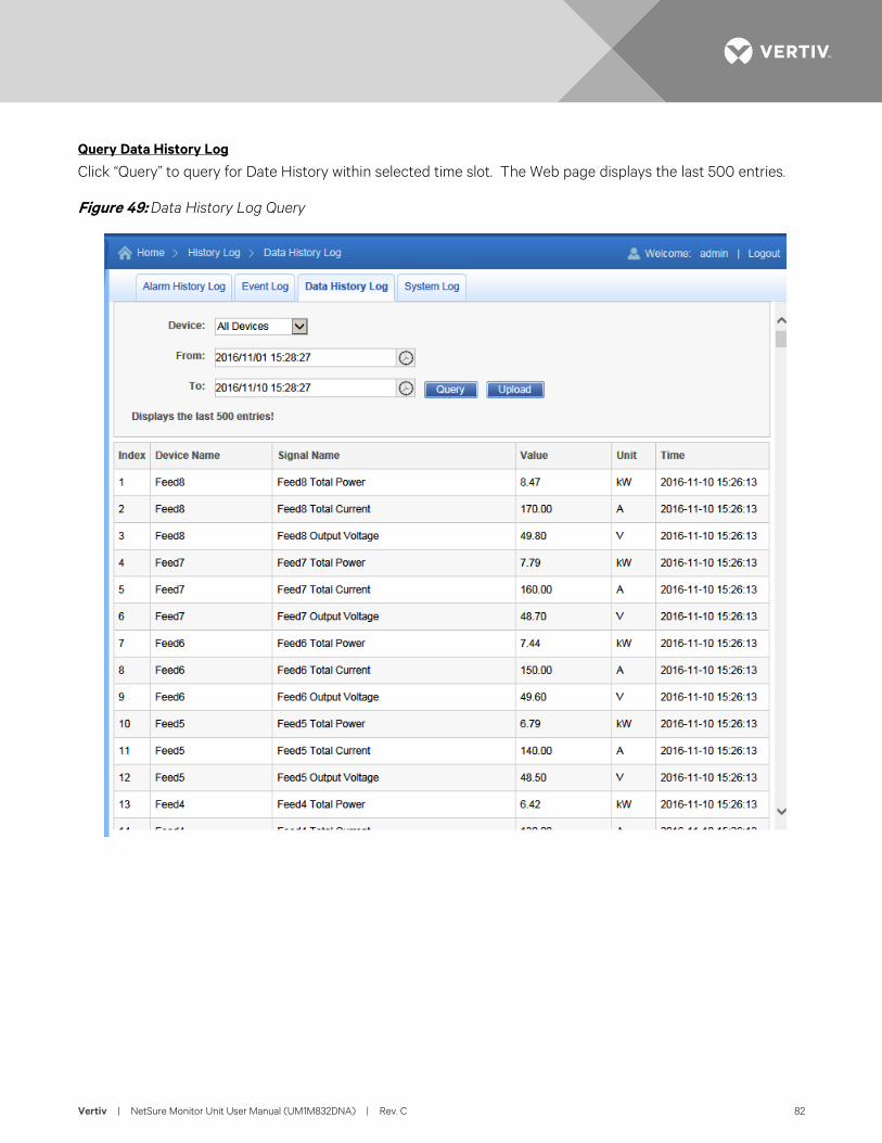
Vertiv | NetSure Monitor Unit User Manual (UM1M832DNA) | Rev. C 82
Query Data History Log
Click “Query” to query for Date History within selected time slot. The Web page displays the last 500 entries.
Figure 49: Data History Log Query
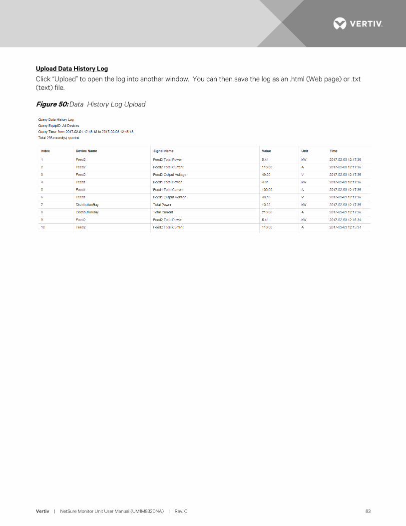
Vertiv | NetSure Monitor Unit User Manual (UM1M832DNA) | Rev. C 83
Upload Data History Log
Click “Upload” to open the log into another window. You can then save the log as an .html (Web page) or .txt (text) file.
Figure 50: Data History Log Upload
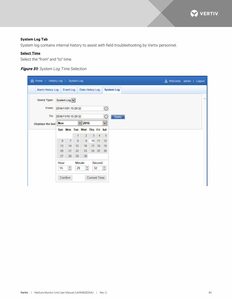
Vertiv | NetSure Monitor Unit User Manual (UM1M832DNA) | Rev. C 84
System Log Tab
System log contains internal history to assist with field troubleshooting by Vertiv personnel.
Select Time
Select the "from" and "to" time.
Figure 51: System Log Time Selection
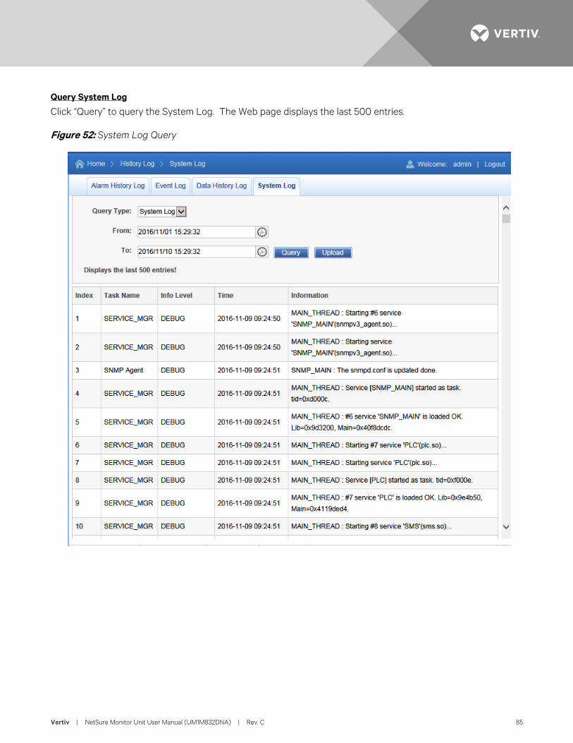
Vertiv | NetSure Monitor Unit User Manual (UM1M832DNA) | Rev. C 85
Query System Log
Click “Query” to query the System Log. The Web page displays the last 500 entries.
Figure 52: System Log Query
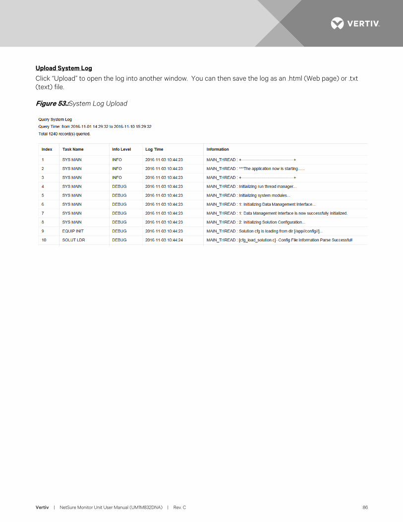
Vertiv | NetSure Monitor Unit User Manual (UM1M832DNA) | Rev. C 86
Upload System Log
Click “Upload” to open the log into another window. You can then save the log as an .html (Web page) or .txt (text) file.
Figure 53.: System Log Upload
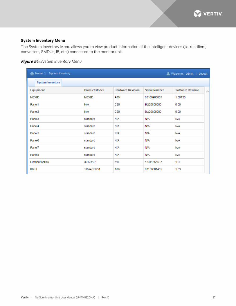
Vertiv | NetSure Monitor Unit User Manual (UM1M832DNA) | Rev. C 87
System Inventory Menu The System Inventory Menu allows you to view product information of the intelligent devices (i.e. rectifiers, converters, SMDUs, IB, etc.) connected to the monitor unit.
Figure 54: System Inventory Menu
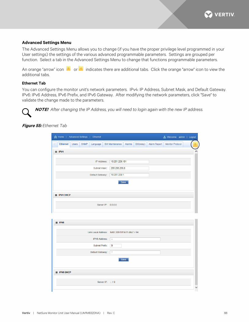
Vertiv | NetSure Monitor Unit User Manual (UM1M832DNA) | Rev. C 88
Advanced Settings Menu The Advanced Settings Menu allows you to change (if you have the proper privilege level programmed in your User settings) the settings of the various advanced programmable parameters. Settings are grouped per function. Select a tab in the Advanced Settings Menu to change that functions programmable parameters.
An orange “arrow” icon or indicates there are additional tabs. Click the orange "arrow" icon to view the additional tabs.
Ethernet Tab
You can configure the monitor unit's network parameters. IPv4: IP Address, Subnet Mask, and Default Gateway. IPv6: IPv6 Address, IPv6 Prefix, and IPv6 Gateway. After modifying the network parameters, click "Save" to validate the change made to the parameters.
NOTE! After changing the IP Address, you will need to login again with the new IP address.
Figure 55: Ethernet Tab
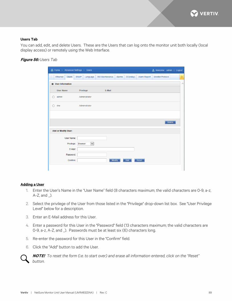
Vertiv | NetSure Monitor Unit User Manual (UM1M832DNA) | Rev. C 89
Users Tab
You can add, edit, and delete Users. These are the Users that can log onto the monitor unit both locally (local display access) or remotely using the Web Interface.
Figure 56: Users Tab
Adding a User
1. Enter the User’s Name in the “User Name” field (8 characters maximum; the valid characters are 0-9, a-z, A-Z, and _).
2. Select the privilege of the User from those listed in the "Privilege" drop-down list box. See "User Privilege Level" below for a description.
3. Enter an E-Mail address for this User.
4. Enter a password for this User in the "Password" field (13 characters maximum; the valid characters are 0-9, a-z, A-Z, and _). Passwords must be at least six (6) characters long.
5. Re-enter the password for this User in the "Confirm" field.
6. Click the "Add" button to add the User.
NOTE! To reset the form (i.e. to start over) and erase all information entered, click on the “Reset” button.
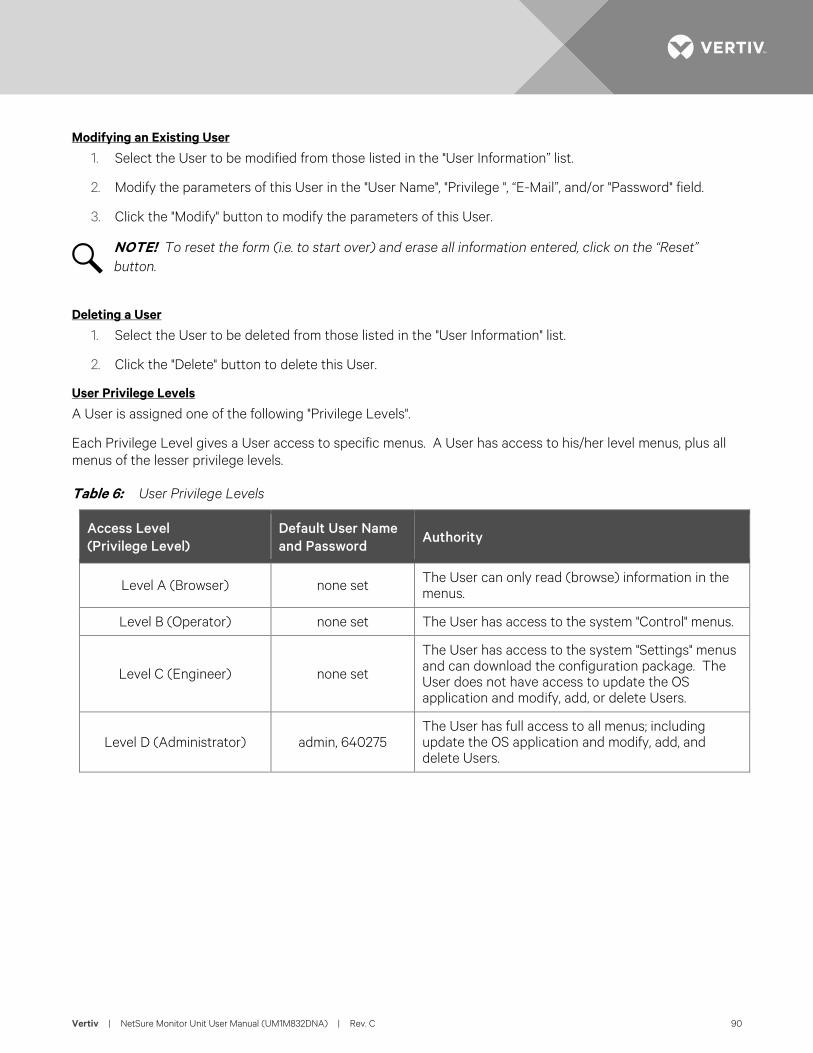
Vertiv | NetSure Monitor Unit User Manual (UM1M832DNA) | Rev. C 90
Modifying an Existing User
1. Select the User to be modified from those listed in the "User Information” list.
2. Modify the parameters of this User in the "User Name", "Privilege ", “E-Mail”, and/or "Password" field.
3. Click the "Modify" button to modify the parameters of this User.
NOTE! To reset the form (i.e. to start over) and erase all information entered, click on the “Reset” button.
Deleting a User
1. Select the User to be deleted from those listed in the "User Information" list.
2. Click the "Delete" button to delete this User.
User Privilege Levels
A User is assigned one of the following "Privilege Levels".
Each Privilege Level gives a User access to specific menus. A User has access to his/her level menus, plus all menus of the lesser privilege levels.
Table 6: User Privilege Levels
Access Level (Privilege Level)
Default User Name and Password
Authority
Level A (Browser) none set The User can only read (browse) information in the menus.
Level B (Operator) none set The User has access to the system "Control" menus.
Level C (Engineer) none set
The User has access to the system "Settings" menus and can download the configuration package. The User does not have access to update the OS application and modify, add, or delete Users.
Level D (Administrator) admin, 640275 The User has full access to all menus; including update the OS application and modify, add, and delete Users.
Vertiv | NetSure Monitor Unit User Manual (UM1M832DNA) | Rev. C 91
SNMP Tab
Configures SNMP V2 and V3 parameters.
Accepted Trap Level Parameter Description
• Accepted Trap Level: Sets SNMP V2 and V3 trap level.
Adding an Entry
1. Enter the parameters in the parameter fields.
2. Click the "Add" button to add the entry.
NOTE! To reset the form (i.e. to start over) and erase all information entered, click on the “Reset” button.
Modifying an Existing Entry
1. Select the Entry to be modified from those listed at the top of the screen.
2. Modify the parameters.
3. Click the "Modify" button to modify the parameters for this Entry.
NOTE! To reset the form (i.e. to start over) and erase all information entered, click on the “Reset” button.
Deleting an Entry
1. Select the Entry to be deleted from those listed at the top of the screen.
2. Click the "Delete" button to delete this Entry.
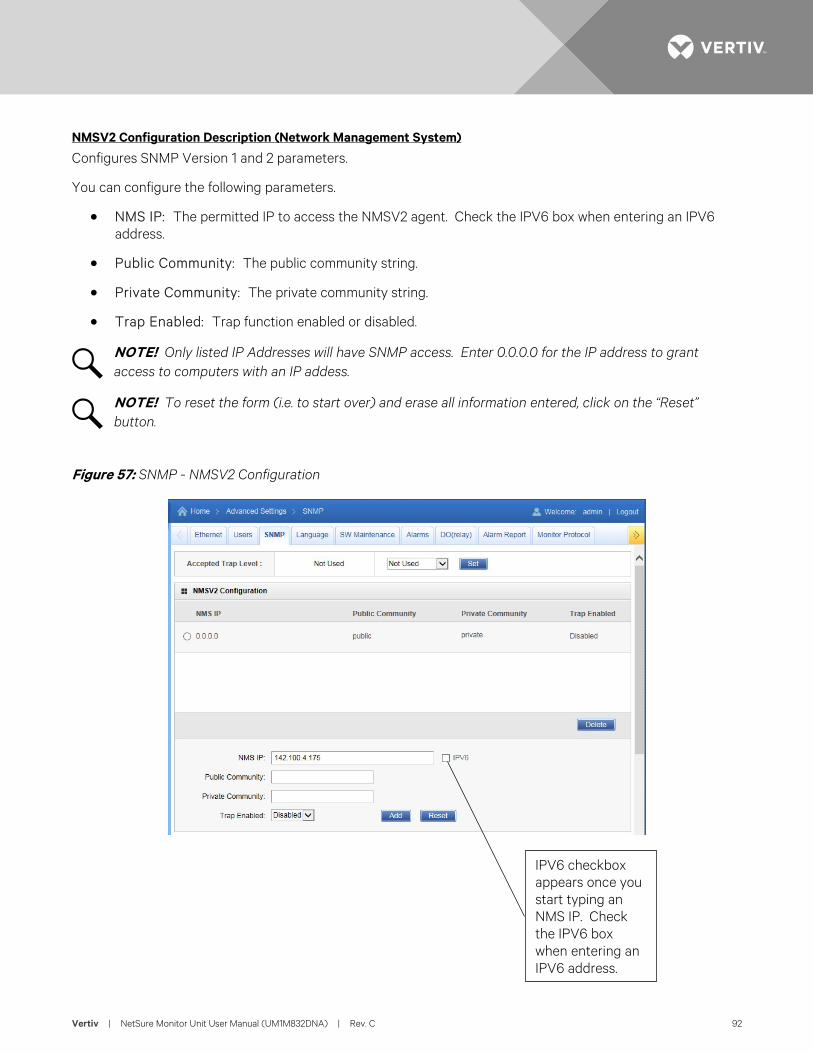
Vertiv | NetSure Monitor Unit User Manual (UM1M832DNA) | Rev. C 92
NMSV2 Configuration Description (Network Management System)
Configures SNMP Version 1 and 2 parameters.
You can configure the following parameters.
• NMS IP: The permitted IP to access the NMSV2 agent. Check the IPV6 box when entering an IPV6 address.
• Public Community: The public community string.
• Private Community: The private community string.
• Trap Enabled: Trap function enabled or disabled.
NOTE! Only listed IP Addresses will have SNMP access. Enter 0.0.0.0 for the IP address to grant access to computers with an IP addess.
NOTE! To reset the form (i.e. to start over) and erase all information entered, click on the “Reset” button.
Figure 57: SNMP - NMSV2 Configuration
IPV6 checkbox appears once you start typing an NMS IP. Check the IPV6 box when entering an IPV6 address.
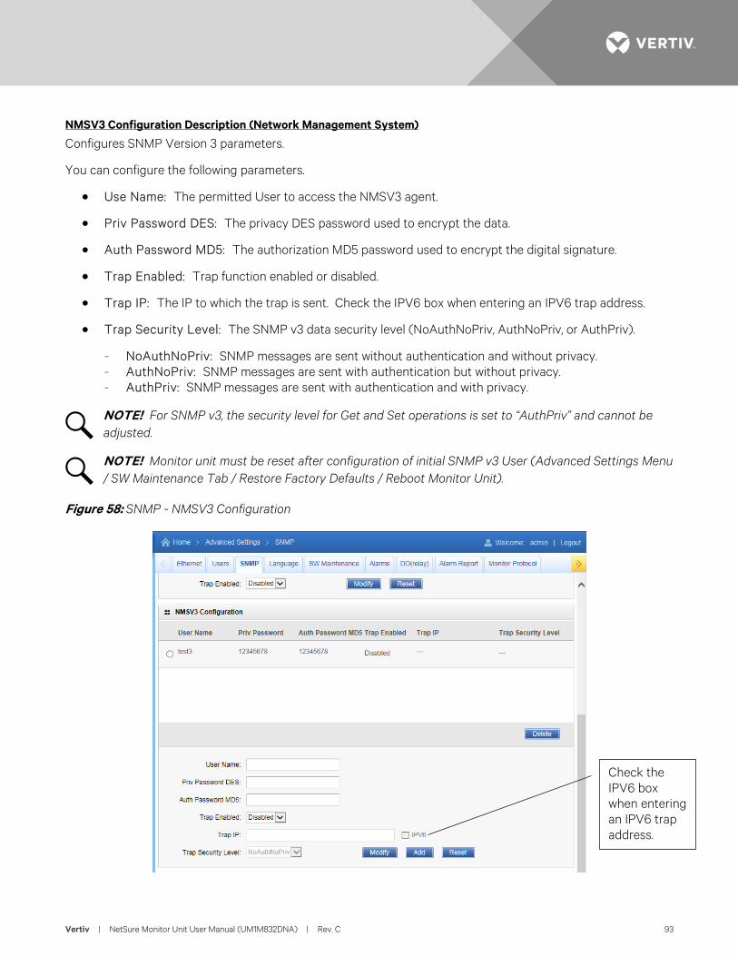
Vertiv | NetSure Monitor Unit User Manual (UM1M832DNA) | Rev. C 93
NMSV3 Configuration Description (Network Management System)
Configures SNMP Version 3 parameters.
You can configure the following parameters.
• Use Name: The permitted User to access the NMSV3 agent.
• Priv Password DES: The privacy DES password used to encrypt the data.
• Auth Password MD5: The authorization MD5 password used to encrypt the digital signature.
• Trap Enabled: Trap function enabled or disabled.
• Trap IP: The IP to which the trap is sent. Check the IPV6 box when entering an IPV6 trap address.
• Trap Security Level: The SNMP v3 data security level (NoAuthNoPriv, AuthNoPriv, or AuthPriv).
- NoAuthNoPriv: SNMP messages are sent without authentication and without privacy. - AuthNoPriv: SNMP messages are sent with authentication but without privacy. - AuthPriv: SNMP messages are sent with authentication and with privacy.
NOTE! For SNMP v3, the security level for Get and Set operations is set to “AuthPriv” and cannot be adjusted.
NOTE! Monitor unit must be reset after configuration of initial SNMP v3 User (Advanced Settings Menu / SW Maintenance Tab / Restore Factory Defaults / Reboot Monitor Unit).
Figure 58: SNMP - NMSV3 Configuration
Check the IPV6 box when entering an IPV6 trap address.
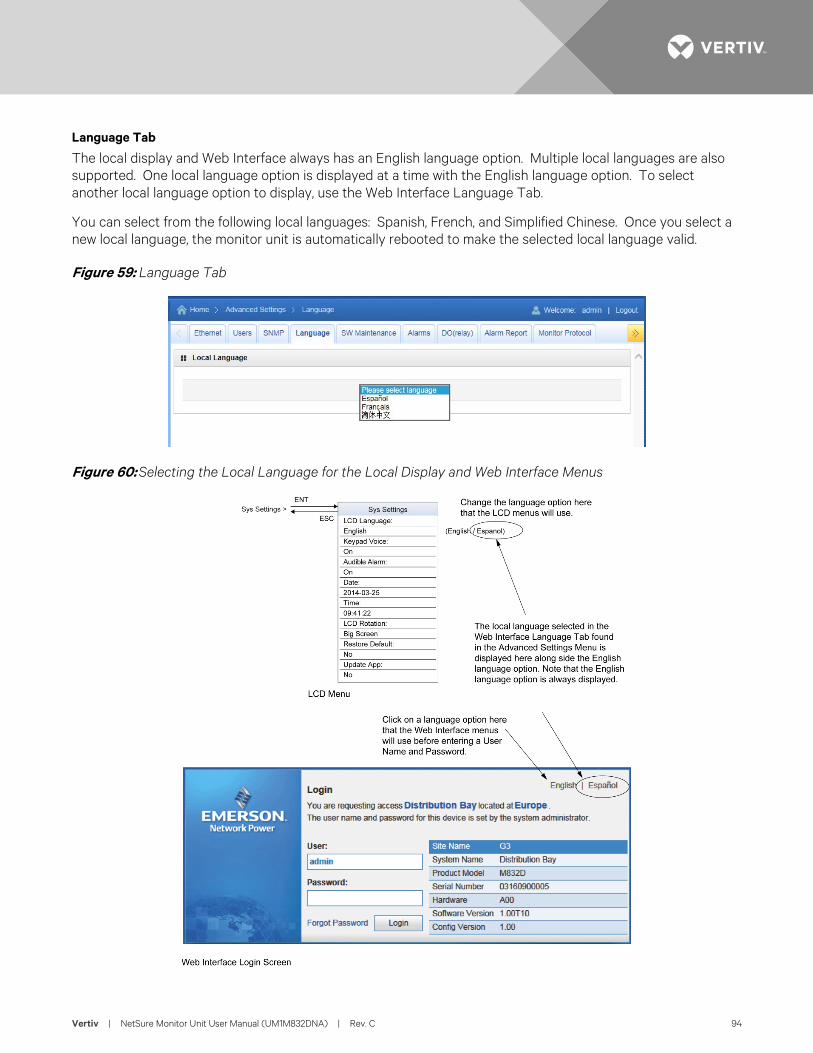
Vertiv | NetSure Monitor Unit User Manual (UM1M832DNA) | Rev. C 94
Language Tab
The local display and Web Interface always has an English language option. Multiple local languages are also supported. One local language option is displayed at a time with the English language option. To select another local language option to display, use the Web Interface Language Tab.
You can select from the following local languages: Spanish, French, and Simplified Chinese. Once you select a new local language, the monitor unit is automatically rebooted to make the selected local language valid.
Figure 59: Language Tab
Figure 60: Selecting the Local Language for the Local Display and Web Interface Menus
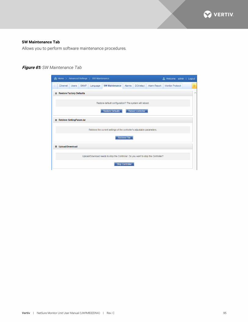
Vertiv | NetSure Monitor Unit User Manual (UM1M832DNA) | Rev. C 95
SW Maintenance Tab
Allows you to perform software maintenance procedures.
Figure 61: SW Maintenance Tab
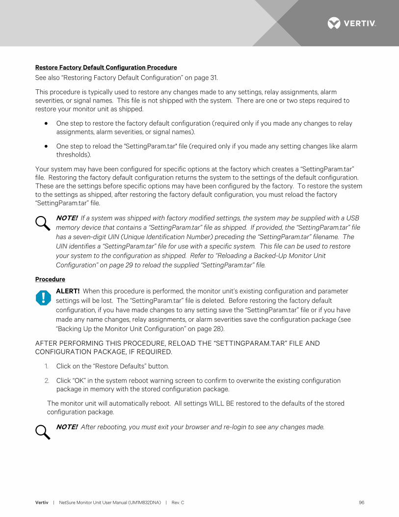
Vertiv | NetSure Monitor Unit User Manual (UM1M832DNA) | Rev. C 96
Restore Factory Default Configuration Procedure
See also “Restoring Factory Default Configuration” on page 31.
This procedure is typically used to restore any changes made to any settings, relay assignments, alarm severities, or signal names. This file is not shipped with the system. There are one or two steps required to restore your monitor unit as shipped.
• One step to restore the factory default configuration (required only if you made any changes to relay assignments, alarm severities, or signal names).
• One step to reload the "SettingParam.tar" file (required only if you made any setting changes like alarm thresholds).
Your system may have been configured for specific options at the factory which creates a “SettingParam.tar” file. Restoring the factory default configuration returns the system to the settings of the default configuration. These are the settings before specific options may have been configured by the factory. To restore the system to the settings as shipped, after restoring the factory default configuration, you must reload the factory “SettingParam.tar” file.
NOTE! If a system was shipped with factory modified settings, the system may be supplied with a USB memory device that contains a “SettingParam.tar” file as shipped. If provided, the “SettingParam.tar” file has a seven-digit UIN (Unique Identification Number) preceding the “SettingParam.tar” filename. The UIN identifies a “SettingParam.tar” file for use with a specific system. This file can be used to restore your system to the configuration as shipped. Refer to “Reloading a Backed-Up Monitor Unit Configuration” on page 29 to reload the supplied “SettingParam.tar” file.
Procedure
ALERT! When this procedure is performed, the monitor unit’s existing configuration and parameter settings will be lost. The “SettingParam.tar” file is deleted. Before restoring the factory default configuration, if you have made changes to any setting save the “SettingParam.tar” file or if you have made any name changes, relay assignments, or alarm severities save the configuration package (see “Backing Up the Monitor Unit Configuration” on page 28).
AFTER PERFORMING THIS PROCEDURE, RELOAD THE “SETTINGPARAM.TAR” FILE AND CONFIGURATION PACKAGE, IF REQUIRED.
1. Click on the “Restore Defaults” button.
2. Click “OK” in the system reboot warning screen to confirm to overwrite the existing configuration package in memory with the stored configuration package.
The monitor unit will automatically reboot. All settings WILL BE restored to the defaults of the stored configuration package.
NOTE! After rebooting, you must exit your browser and re-login to see any changes made.
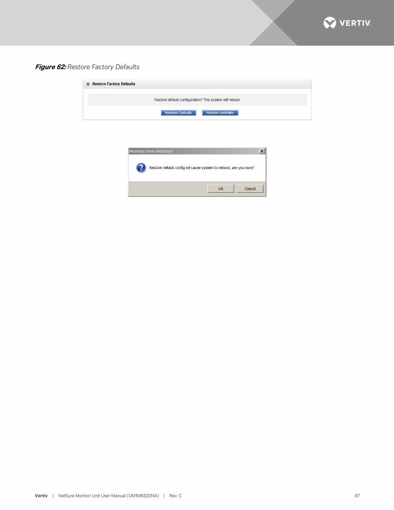
Vertiv | NetSure Monitor Unit User Manual (UM1M832DNA) | Rev. C 97
Figure 62: Restore Factory Defaults
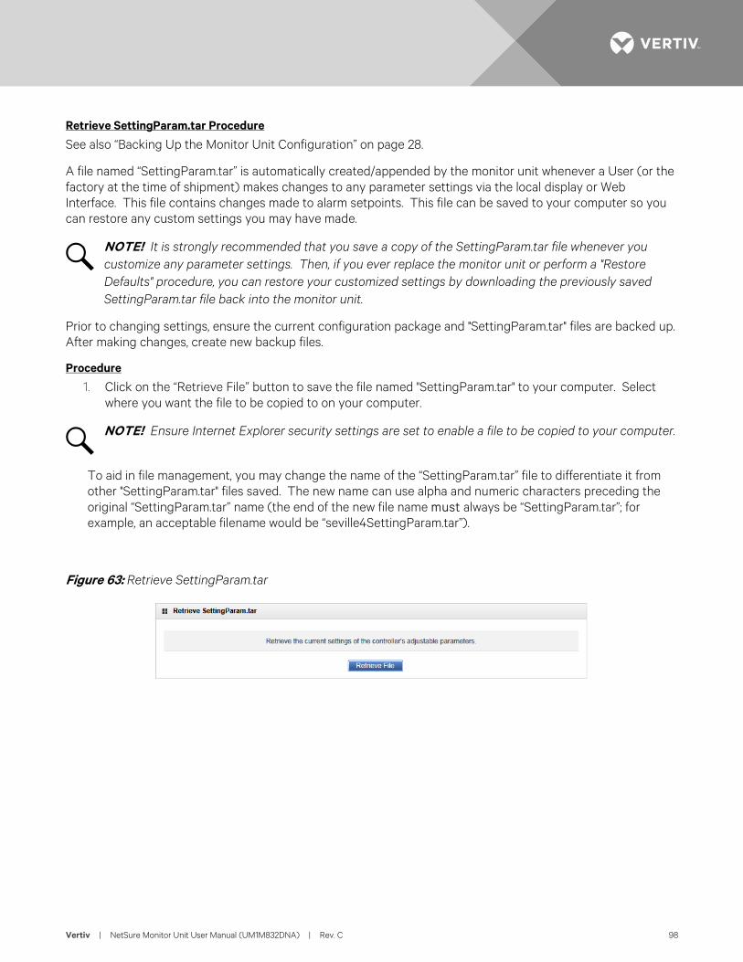
Vertiv | NetSure Monitor Unit User Manual (UM1M832DNA) | Rev. C 98
Retrieve SettingParam.tar Procedure
See also “Backing Up the Monitor Unit Configuration” on page 28.
A file named “SettingParam.tar” is automatically created/appended by the monitor unit whenever a User (or the factory at the time of shipment) makes changes to any parameter settings via the local display or Web Interface. This file contains changes made to alarm setpoints. This file can be saved to your computer so you can restore any custom settings you may have made.
NOTE! It is strongly recommended that you save a copy of the SettingParam.tar file whenever you customize any parameter settings. Then, if you ever replace the monitor unit or perform a "Restore Defaults" procedure, you can restore your customized settings by downloading the previously saved SettingParam.tar file back into the monitor unit.
Prior to changing settings, ensure the current configuration package and "SettingParam.tar" files are backed up. After making changes, create new backup files.
Procedure
1. Click on the “Retrieve File” button to save the file named "SettingParam.tar" to your computer. Select where you want the file to be copied to on your computer.
NOTE! Ensure Internet Explorer security settings are set to enable a file to be copied to your computer.
To aid in file management, you may change the name of the “SettingParam.tar” file to differentiate it from other "SettingParam.tar" files saved. The new name can use alpha and numeric characters preceding the original “SettingParam.tar” name (the end of the new file name must always be “SettingParam.tar”; for example, an acceptable filename would be “seville4SettingParam.tar”).
Figure 63: Retrieve SettingParam.tar
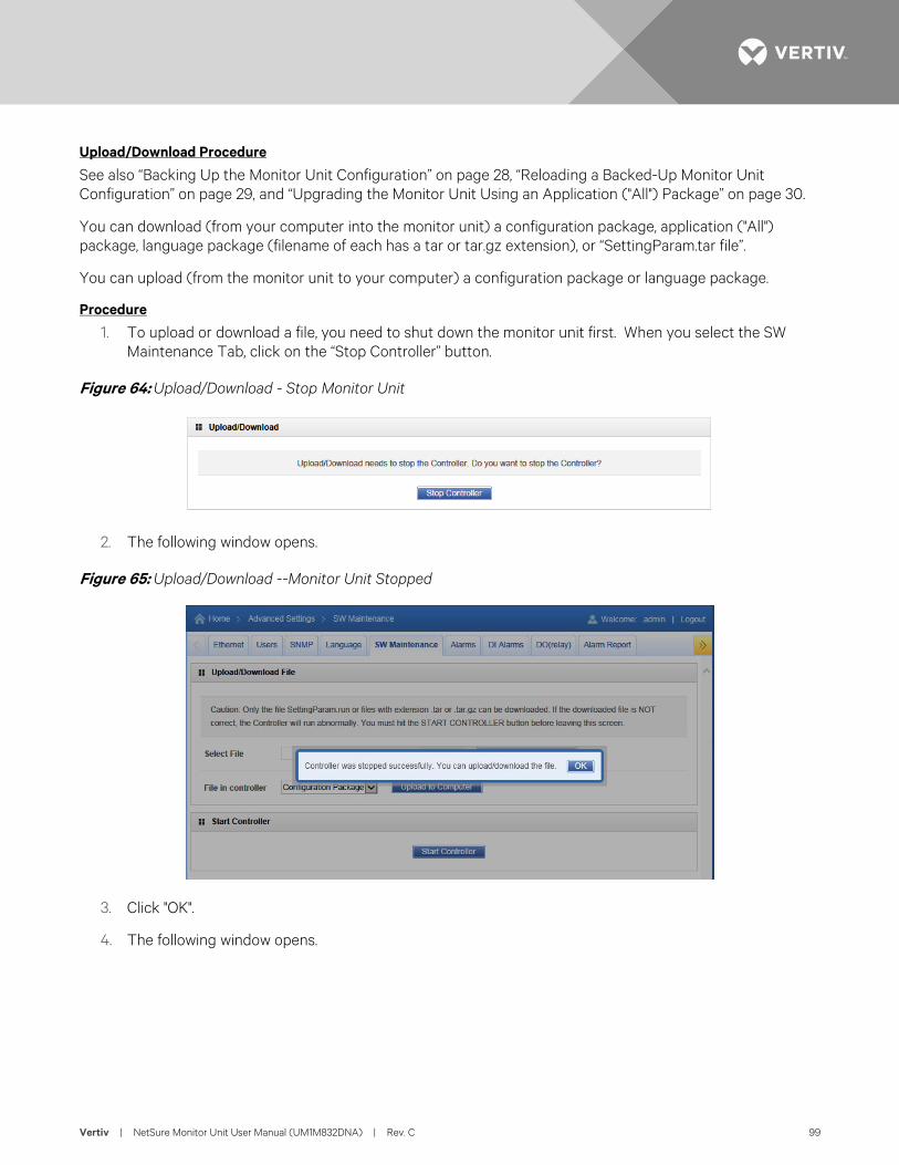
Vertiv | NetSure Monitor Unit User Manual (UM1M832DNA) | Rev. C 99
Upload/Download Procedure
See also “Backing Up the Monitor Unit Configuration” on page 28, “Reloading a Backed-Up Monitor Unit Configuration” on page 29, and “Upgrading the Monitor Unit Using an Application ("All") Package” on page 30.
You can download (from your computer into the monitor unit) a configuration package, application ("All") package, language package (filename of each has a tar or tar.gz extension), or “SettingParam.tar file”.
You can upload (from the monitor unit to your computer) a configuration package or language package.
Procedure
1. To upload or download a file, you need to shut down the monitor unit first. When you select the SW Maintenance Tab, click on the “Stop Controller” button.
Figure 64: Upload/Download - Stop Monitor Unit
2. The following window opens.
Figure 65: Upload/Download --Monitor Unit Stopped
3. Click "OK".
4. The following window opens.
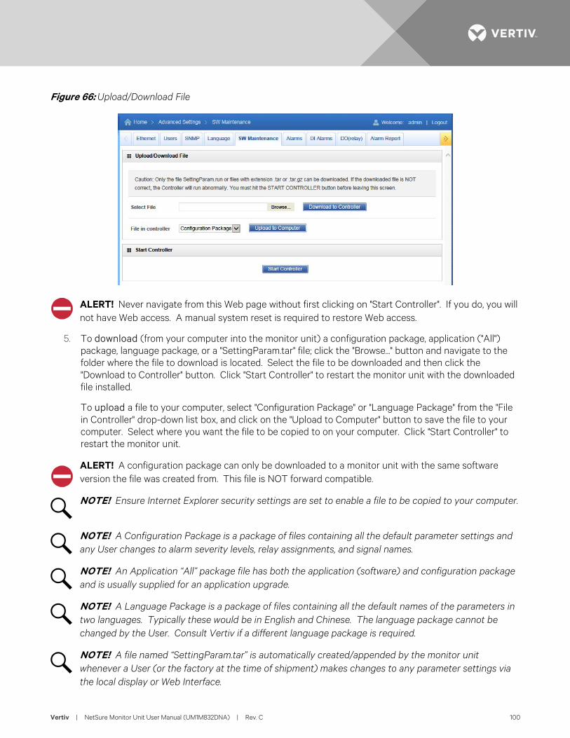
Vertiv | NetSure Monitor Unit User Manual (UM1M832DNA) | Rev. C 100
Figure 66: Upload/Download File
ALERT! Never navigate from this Web page without first clicking on "Start Controller". If you do, you will not have Web access. A manual system reset is required to restore Web access.
5. To download (from your computer into the monitor unit) a configuration package, application ("All") package, language package, or a "SettingParam.tar" file; click the "Browse..." button and navigate to the folder where the file to download is located. Select the file to be downloaded and then click the "Download to Controller" button. Click "Start Controller" to restart the monitor unit with the downloaded file installed.
To upload a file to your computer, select "Configuration Package" or "Language Package" from the "File in Controller" drop-down list box, and click on the "Upload to Computer" button to save the file to your computer. Select where you want the file to be copied to on your computer. Click "Start Controller" to restart the monitor unit.
ALERT! A configuration package can only be downloaded to a monitor unit with the same software version the file was created from. This file is NOT forward compatible.
NOTE! Ensure Internet Explorer security settings are set to enable a file to be copied to your computer.
NOTE! A Configuration Package is a package of files containing all the default parameter settings and any User changes to alarm severity levels, relay assignments, and signal names.
NOTE! An Application “All” package file has both the application (software) and configuration package and is usually supplied for an application upgrade.
NOTE! A Language Package is a package of files containing all the default names of the parameters in two languages. Typically these would be in English and Chinese. The language package cannot be changed by the User. Consult Vertiv if a different language package is required.
NOTE! A file named “SettingParam.tar” is automatically created/appended by the monitor unit whenever a User (or the factory at the time of shipment) makes changes to any parameter settings via the local display or Web Interface.
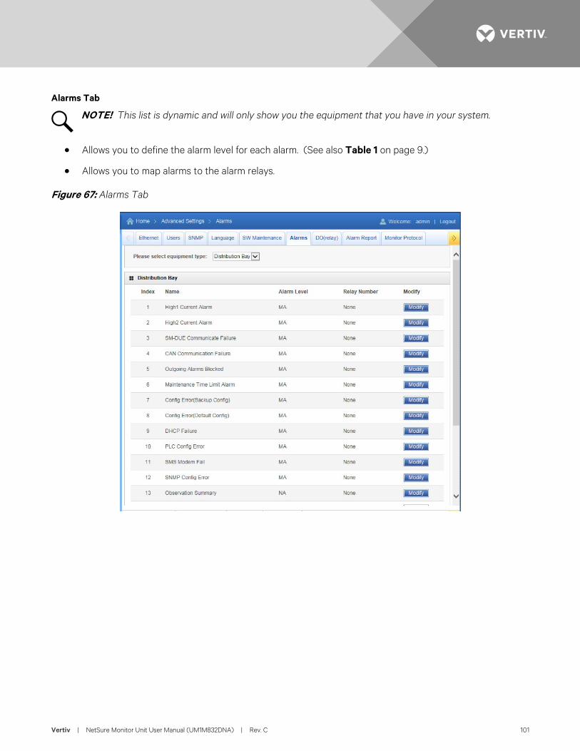
Vertiv | NetSure Monitor Unit User Manual (UM1M832DNA) | Rev. C 101
Alarms Tab
NOTE! This list is dynamic and will only show you the equipment that you have in your system.
• Allows you to define the alarm level for each alarm. (See also Table 1 on page 9.)
• Allows you to map alarms to the alarm relays.
Figure 67: Alarms Tab
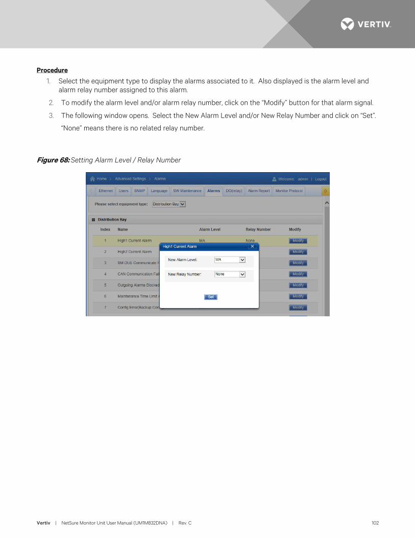
Vertiv | NetSure Monitor Unit User Manual (UM1M832DNA) | Rev. C 102
Procedure
1. Select the equipment type to display the alarms associated to it. Also displayed is the alarm level and alarm relay number assigned to this alarm.
2. To modify the alarm level and/or alarm relay number, click on the “Modify” button for that alarm signal.
3. The following window opens. Select the New Alarm Level and/or New Relay Number and click on “Set”.
“None” means there is no related relay number.
Figure 68: Setting Alarm Level / Relay Number
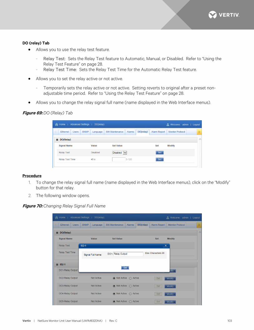
Vertiv | NetSure Monitor Unit User Manual (UM1M832DNA) | Rev. C 103
DO (relay) Tab
• Allows you to use the relay test feature.
- Relay Test: Sets the Relay Test feature to Automatic, Manual, or Disabled. Refer to “Using the Relay Test Feature” on page 28.
- Relay Test Time: Sets the Relay Test Time for the Automatic Relay Test feature.
• Allows you to set the relay active or not active.
- Temporarily sets the relay active or not active. Setting reverts to original after a preset non-adjustable time period. Refer to “Using the Relay Test Feature” on page 28.
• Allows you to change the relay signal full name (name displayed in the Web Interface menus).
Figure 69: DO (Relay) Tab
Procedure
1. To change the relay signal full name (name displayed in the Web Interface menus), click on the “Modify” button for that relay.
2. The following window opens.
Figure 70: Changing Relay Signal Full Name
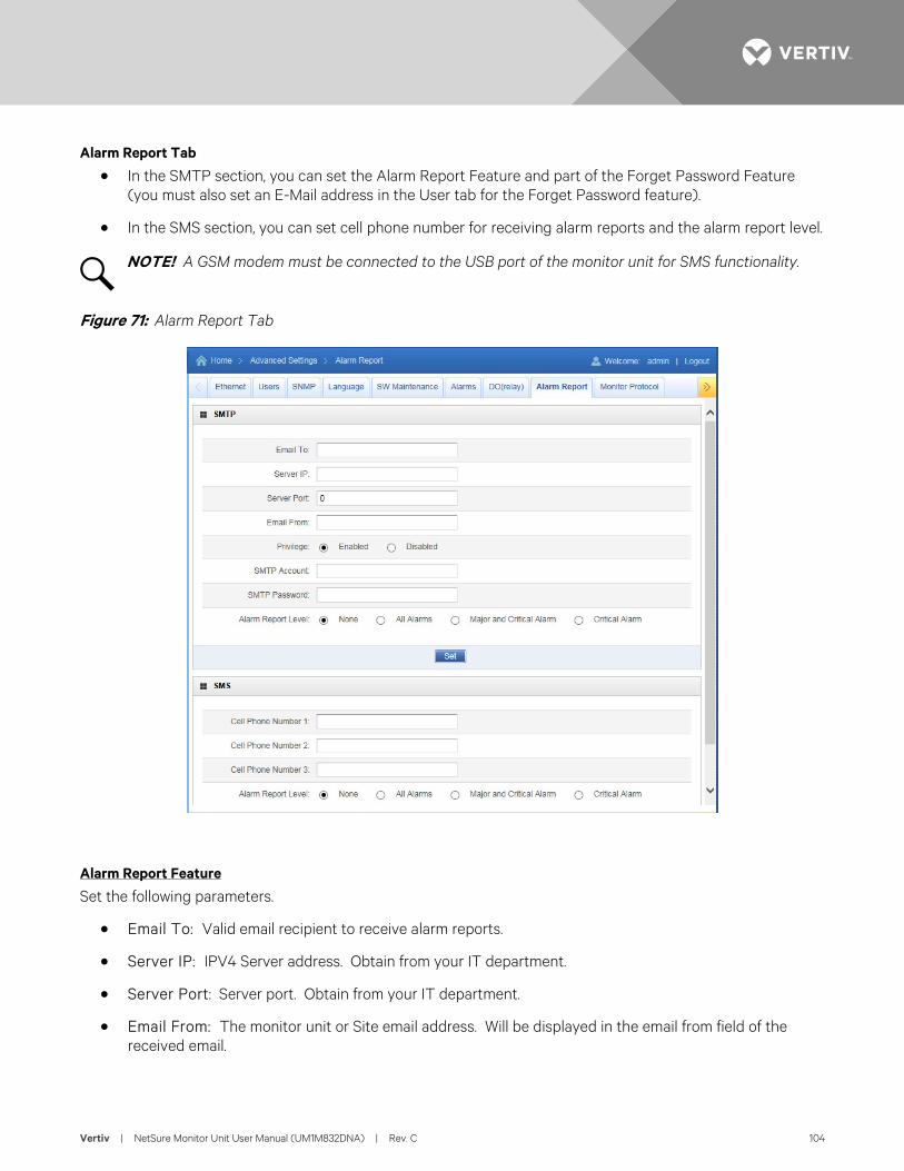
Vertiv | NetSure Monitor Unit User Manual (UM1M832DNA) | Rev. C 104
Alarm Report Tab
• In the SMTP section, you can set the Alarm Report Feature and part of the Forget Password Feature (you must also set an E-Mail address in the User tab for the Forget Password feature).
• In the SMS section, you can set cell phone number for receiving alarm reports and the alarm report level.
NOTE! A GSM modem must be connected to the USB port of the monitor unit for SMS functionality.
Figure 71: Alarm Report Tab
Alarm Report Feature
Set the following parameters.
• Email To: Valid email recipient to receive alarm reports.
• Server IP: IPV4 Server address. Obtain from your IT department.
• Server Port: Server port. Obtain from your IT department.
• Email From: The monitor unit or Site email address. Will be displayed in the email from field of the received email.
Vertiv | NetSure Monitor Unit User Manual (UM1M832DNA) | Rev. C 105
• Privilege: Select Enabled (if email authentication is required) or Disabled as required (see your IT department). When enabled, set the following parameters.
- SMTP Account: SMTP account number. Obtain from your IT department. - SMTP Password: SMTP password. Obtain from your IT department.
• Alarm Report Level: Select the level of alarm reports you want to receive.
Forget Password Feature
Set the following parameters. Also set an E-Mail address in the User tab. This is the email the password will be sent to.
• Email To: Any valid email recipient. This can be the same email address set in the User tab if not also using the alarm report feature.
• Server IP: IPV4 Server address. Obtain from your IT department.
• Server Port: Server port. Obtain from your IT department.
• Email From: The monitor unit or Site email address. Will be displayed in the email from field of the received email.
• Privilege: Select Enabled (if email authentication is required) or Disabled as required (see your IT department). When enabled, set the following parameters.
- SMTP Account: SMTP account number. Obtain from your IT department. - SMTP Password: SMTP password. Obtain from your IT department.
• Alarm Report Level: If you only want to use the Forgot Password Feature, set the Alarm Report Level to None.
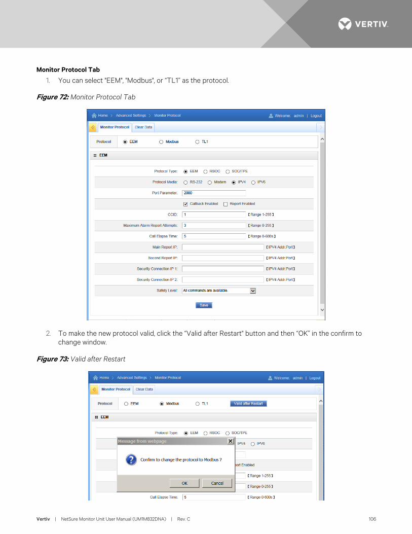
Vertiv | NetSure Monitor Unit User Manual (UM1M832DNA) | Rev. C 106
Monitor Protocol Tab
1. You can select "EEM", "Modbus", or “TL1” as the protocol.
Figure 72: Monitor Protocol Tab
2. To make the new protocol valid, click the “Valid after Restart" button and then “OK” in the confirm to change window.
Figure 73: Valid after Restart
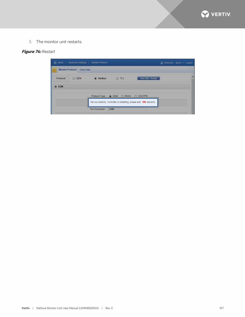
Vertiv | NetSure Monitor Unit User Manual (UM1M832DNA) | Rev. C 107
3. The monitor unit restarts.
Figure 74: Restart
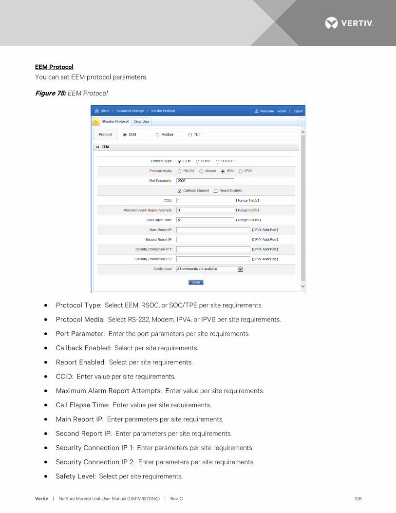
Vertiv | NetSure Monitor Unit User Manual (UM1M832DNA) | Rev. C 108
EEM Protocol
You can set EEM protocol parameters.
Figure 75: EEM Protocol
• Protocol Type: Select EEM, RSOC, or SOC/TPE per site requirements.
• Protocol Media: Select RS-232, Modem, IPV4, or IPV6 per site requirements.
• Port Parameter: Enter the port parameters per site requirements.
• Callback Enabled: Select per site requirements.
• Report Enabled: Select per site requirements.
• CCID: Enter value per site requirements.
• Maximum Alarm Report Attempts: Enter value per site requirements.
• Call Elapse Time: Enter value per site requirements.
• Main Report IP: Enter parameters per site requirements.
• Second Report IP: Enter parameters per site requirements.
• Security Connection IP 1: Enter parameters per site requirements.
• Security Connection IP 2: Enter parameters per site requirements.
• Safety Level: Select per site requirements.
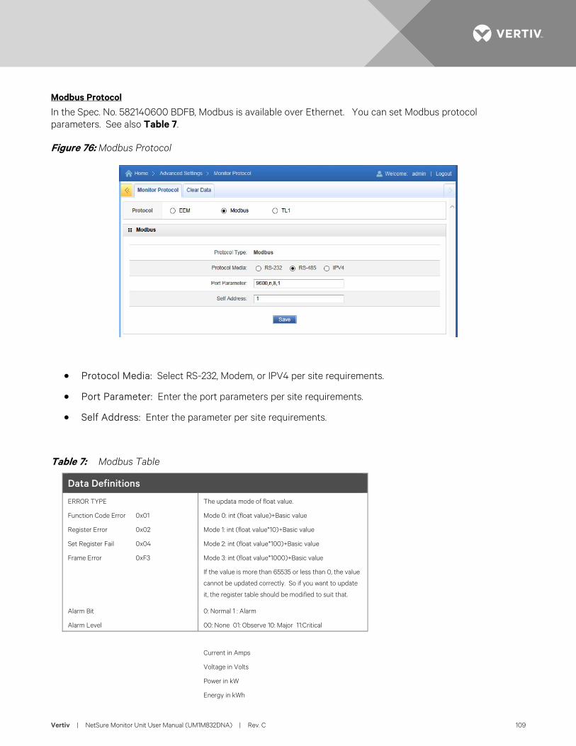
Vertiv | NetSure Monitor Unit User Manual (UM1M832DNA) | Rev. C 109
Modbus Protocol
In the Spec. No. 582140600 BDFB, Modbus is available over Ethernet. You can set Modbus protocol parameters. See also Table 7.
Figure 76: Modbus Protocol
• Protocol Media: Select RS-232, Modem, or IPV4 per site requirements.
• Port Parameter: Enter the port parameters per site requirements.
• Self Address: Enter the parameter per site requirements.
Table 7: Modbus Table
Data Definitions
ERROR TYPE The updata mode of float value.
Function Code Error 0x01 Mode 0: int (float value)+Basic value
Register Error 0x02 Mode 1: int (float value*10)+Basic value
Set Register Fail 0x04 Mode 2: int (float value*100)+Basic value
Frame Error 0xF3 Mode 3: int (float value*1000)+Basic value
If the value is more than 65535 or less than 0, the value
cannot be updated correctly. So if you want to update
it, the register table should be modified to suit that.
Alarm Bit 0: Normal 1 : Alarm
Alarm Level 00: None 01: Observe 10: Major 11:Critical
Current in Amps
Voltage in Volts
Power in kW
Energy in kWh
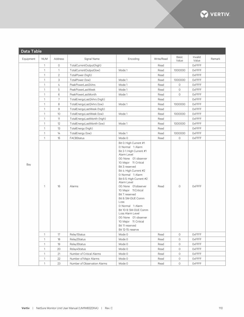
Vertiv | NetSure Monitor Unit User Manual (UM1M832DNA) | Rev. C 110
Data Table
Equipment NUM Address Signal Name Encoding Write/Read Basic Value
Invalid Value Remark
Bay
1 0 TotalCurrentOutput(high) Read 0xFFFF
1 1 TotalCurrentOutput(low) Mode 1 Read 1000000 0xFFFF
1 2 TotalPower (high) Read 0xFFFF
1 3 TotalPower (low) Mode 1 Read 1000000 0xFFFF
1 4 PeakPowerLast24hrs Mode 1 Read 0 0xFFFF
1 5 PeakPowerLastWeek Mode 1 Read 0 0xFFFF
1 6 PeakPowerLastMonth Mode 1 Read 0 0xFFFF
1 7 TotalEnergyLast24hrs (high) Read 0xFFFF
1 8 TotalEnergyLast24hrs (low) Mode 1 Read 1000000 0xFFFF
1 9 TotalEnergyLastWeek (high) Read 0xFFFF
1 10 TotalEnergyLastWeek (low) Mode 1 Read 1000000 0xFFFF
1 11 TotalEnergyLastMonth (high) Read 0xFFFF
1 12 TotalEnergyLastMonth (low) Mode 1 Read 1000000 0xFFFF
1 13 TotalEnergy (high) Read 0xFFFF
1 14 TotalEnergy (low) Mode 1 Read 1000000 0xFFFF
1 15 FACBStatus Mode 0 Read 0 0xFFFF
1 16 Alarms
Bit 0: High Current #1 0: Normal 1: Alarm Bit 2-1: High Current #1 Alarm Level 00: None 01: observer 10: Major 11: Critical Bit 3: reserved Bit 4: High Current #2 0: Normal 1: Alarm Bit 6-5: High Current #2 Alarm Level 00: None 01:observer 10: Major 11:Critical Bit 7: reserved Bit 8: SM-DUE Comm Loss 0: Normal 1: Alarm Bit 10-9: SM-DUE Comm Loss Alarm Level 00: None 01: observer 10: Major 11: Critical Bit 11 reserved Bit 12-15: reserve
Read 0 0xFFFF
1 17 Relay1Status Mode 0 Read 0 0xFFFF
1 18 Relay2Status Mode 0 Read 0 0xFFFF
1 19 Relay3Status Mode 0 Read 0 0xFFFF
1 20 Relay4Status Mode 0 Read 0 0xFFFF
1 21 Number of Critical Alarms Mode 0 Read 0 0xFFFF
1 22 Number of Major Alarms Mode 0 Read 0 0xFFFF
1 23 Number of Observation Alarms Mode 0 Read 0 0xFFFF
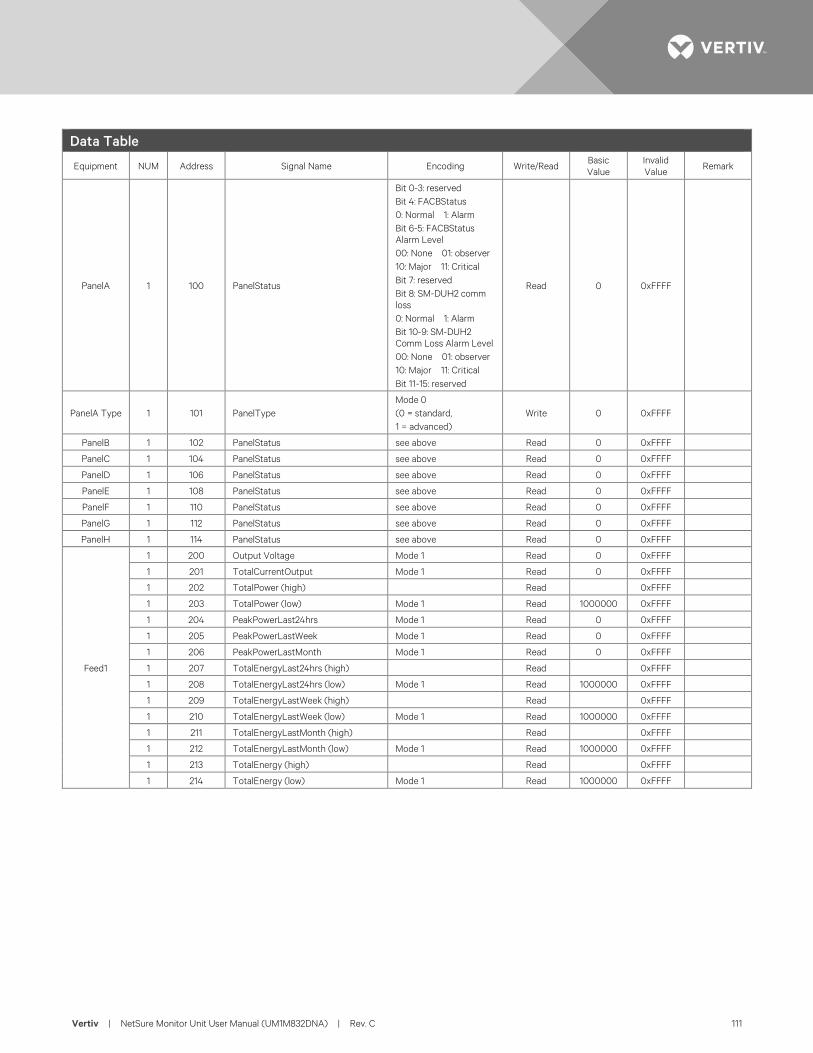
Vertiv | NetSure Monitor Unit User Manual (UM1M832DNA) | Rev. C 111
Data Table
Equipment NUM Address Signal Name Encoding Write/Read Basic Value
Invalid Value Remark
PanelA 1 100 PanelStatus
Bit 0-3: reserved Bit 4: FACBStatus 0: Normal 1: Alarm Bit 6-5: FACBStatus Alarm Level 00: None 01: observer 10: Major 11: Critical Bit 7: reserved Bit 8: SM-DUH2 comm loss 0: Normal 1: Alarm Bit 10-9: SM-DUH2 Comm Loss Alarm Level 00: None 01: observer 10: Major 11: Critical Bit 11-15: reserved
Read 0 0xFFFF
PanelA Type 1 101 PanelType Mode 0 (0 = standard, 1 = advanced)
Write 0 0xFFFF
PanelB 1 102 PanelStatus see above Read 0 0xFFFF
PanelC 1 104 PanelStatus see above Read 0 0xFFFF
PanelD 1 106 PanelStatus see above Read 0 0xFFFF
PanelE 1 108 PanelStatus see above Read 0 0xFFFF
PanelF 1 110 PanelStatus see above Read 0 0xFFFF
PanelG 1 112 PanelStatus see above Read 0 0xFFFF
PanelH 1 114 PanelStatus see above Read 0 0xFFFF
Feed1
1 200 Output Voltage Mode 1 Read 0 0xFFFF
1 201 TotalCurrentOutput Mode 1 Read 0 0xFFFF
1 202 TotalPower (high) Read 0xFFFF
1 203 TotalPower (low) Mode 1 Read 1000000 0xFFFF
1 204 PeakPowerLast24hrs Mode 1 Read 0 0xFFFF
1 205 PeakPowerLastWeek Mode 1 Read 0 0xFFFF
1 206 PeakPowerLastMonth Mode 1 Read 0 0xFFFF
1 207 TotalEnergyLast24hrs (high) Read 0xFFFF
1 208 TotalEnergyLast24hrs (low) Mode 1 Read 1000000 0xFFFF
1 209 TotalEnergyLastWeek (high) Read 0xFFFF
1 210 TotalEnergyLastWeek (low) Mode 1 Read 1000000 0xFFFF
1 211 TotalEnergyLastMonth (high) Read 0xFFFF
1 212 TotalEnergyLastMonth (low) Mode 1 Read 1000000 0xFFFF
1 213 TotalEnergy (high) Read 0xFFFF
1 214 TotalEnergy (low) Mode 1 Read 1000000 0xFFFF
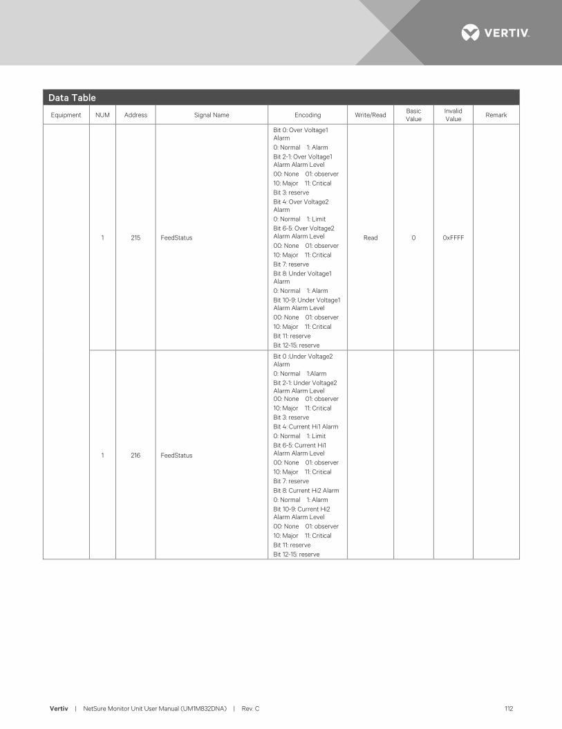
Vertiv | NetSure Monitor Unit User Manual (UM1M832DNA) | Rev. C 112
Data Table
Equipment NUM Address Signal Name Encoding Write/Read Basic Value
Invalid Value Remark
1 215 FeedStatus
Bit 0: Over Voltage1 Alarm 0: Normal 1: Alarm Bit 2-1: Over Voltage1 Alarm Alarm Level 00: None 01: observer 10: Major 11: Critical Bit 3: reserve Bit 4: Over Voltage2 Alarm 0: Normal 1: Limit Bit 6-5: Over Voltage2 Alarm Alarm Level 00: None 01: observer 10: Major 11: Critical Bit 7: reserve Bit 8: Under Voltage1 Alarm 0: Normal 1: Alarm Bit 10-9: Under Voltage1 Alarm Alarm Level 00: None 01: observer 10: Major 11: Critical Bit 11: reserve Bit 12-15: reserve
Read 0 0xFFFF
1 216 FeedStatus
Bit 0 :Under Voltage2 Alarm 0: Normal 1:Alarm Bit 2-1: Under Voltage2 Alarm Alarm Level 00: None 01: observer 10: Major 11: Critical Bit 3: reserve Bit 4: Current Hi1 Alarm 0: Normal 1: Limit Bit 6-5: Current Hi1 Alarm Alarm Level 00: None 01: observer 10: Major 11: Critical Bit 7: reserve Bit 8: Current Hi2 Alarm 0: Normal 1: Alarm Bit 10-9: Current Hi2 Alarm Alarm Level 00: None 01: observer 10: Major 11: Critical Bit 11: reserve Bit 12-15: reserve
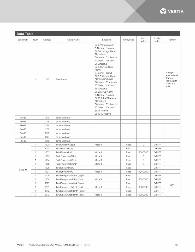
Vertiv | NetSure Monitor Unit User Manual (UM1M832DNA) | Rev. C 113
Data Table
Equipment NUM Address Signal Name Encoding Write/Read Basic Value
Invalid Value Remark
1 217 FeedStatus
Bit 0: Voltage Alarm 0: Normal 1: Alarm Bit 2-1: Voltage Alarm Alarm Level 00: None 01: observer 10: Major 11: Critical Bit 3: reserve Bit 4: Current High Alarm 0:Normal 1:Limit Bit 6-5: Current High Alarm Alarm Level 00: None 01:observer 10: Major 11: Critical Bit 7: reserve Bit 8: FA/CB Alarm 0: Normal 1: Alarm Bit 10-9: FA/CB Alarm Alarm Level 00: None 01: observer 10: Major 11: Critical Bit 11: reserve Bit 12-15: reserve
Voltage Alarm 0 and Current High Alarm 0 are not exist
Feed2 218 same as above
Feed3 236 same as above
Feed4 254 same as above
Feed5 272 same as above
Feed6 290 same as above
Feed7 308 same as above
Feed8 326 same as above
Load #1
1 1000 TotalCurrentOutput Mode 1 Read 0 0xFFFF
1 1001 TotalPower (high) Read 0xFFFF
1 1002 TotalPower (low) Mode 1 Read 1000000 0xFFFF
1 1003 PeakPowerLast24hrs Mode 1 Read 0 0xFFFF
1 1004 PeakPowerLastWeek Mode 1 Read 0 0xFFFF
1 1005 PeakPowerLastMonth Mode 1 Read 0 0xFFFF
1 1006 TotalEnergy (high) Read 0xFFFF
1 1007 TotalEnergy (low) Mode 1 Read 1000000 0xFFFF
1 1008 TotalEnergyLast24hrs (high) Read 0xFFFF
N/P
1 1009 TotalEnergyLast24hrs (low) Mode 1 Read 1000000 0xFFFF
1 1010 TotalEnergyLastWeek (high) Read 0xFFFF
1 1011 TotalEnergyLastWeek (low) Mode 1 Read 1000000 0xFFFF
1 1012 TotalEnergyLastMonth (high) Read 0xFFFF
1 1013 TotalEnergyLastMonth (low) Mode 1 Read 1000000 0xFFFF
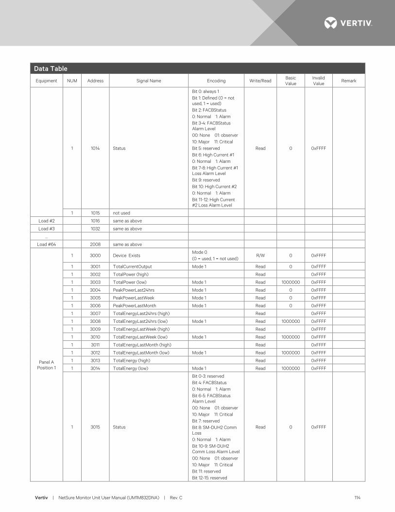
Vertiv | NetSure Monitor Unit User Manual (UM1M832DNA) | Rev. C 114
Data Table
Equipment NUM Address Signal Name Encoding Write/Read Basic Value
Invalid Value Remark
1 1014 Status
Bit 0: always 1 Bit 1: Defined (0 = not used, 1 = used) Bit 2: FACBStatus 0: Normal 1: Alarm Bit 3-4: FACBStatus Alarm Level 00: None 01: observer 10: Major 11: Critical Bit 5: reserved Bit 6: High Current #1 0: Normal 1: Alarm Bit 7-8: High Current #1 Loss Alarm Level Bit 9: reserved Bit 10: High Current #2 0: Normal 1: Alarm Bit 11-12: High Current #2 Loss Alarm Level
Read 0 0xFFFF
1 1015 not used
Load #2 1016 same as above
Load #3 1032 same as above
…
Load #64 2008 same as above
Panel A Position 1
1 3000 Device Exists Mode 0 (0 = used, 1 = not used)
R/W 0 0xFFFF
1 3001 TotalCurrentOutput Mode 1 Read 0 0xFFFF
1 3002 TotalPower (high) Read 0xFFFF
1 3003 TotalPower (low) Mode 1 Read 1000000 0xFFFF
1 3004 PeakPowerLast24hrs Mode 1 Read 0 0xFFFF
1 3005 PeakPowerLastWeek Mode 1 Read 0 0xFFFF
1 3006 PeakPowerLastMonth Mode 1 Read 0 0xFFFF
1 3007 TotalEnergyLast24hrs (high) Read 0xFFFF
1 3008 TotalEnergyLast24hrs (low) Mode 1 Read 1000000 0xFFFF
1 3009 TotalEnergyLastWeek (high) Read 0xFFFF
1 3010 TotalEnergyLastWeek (low) Mode 1 Read 1000000 0xFFFF
1 3011 TotalEnergyLastMonth (high) Read 0xFFFF
1 3012 TotalEnergyLastMonth (low) Mode 1 Read 1000000 0xFFFF
1 3013 TotalEnergy (high) Read 0xFFFF
1 3014 TotalEnergy (low) Mode 1 Read 1000000 0xFFFF
1 3015 Status
Bit 0-3: reserved Bit 4: FACBStatus 0: Normal 1: Alarm Bit 6-5: FACBStatus Alarm Level 00: None 01: observer 10: Major 11: Critical Bit 7: reserved Bit 8: SM-DUH2 Comm Loss 0: Normal 1: Alarm Bit 10-9: SM-DUH2 Comm Loss Alarm Level 00: None 01: observer 10: Major 11: Critical Bit 11: reserved Bit 12-15: reserved
Read 0 0xFFFF
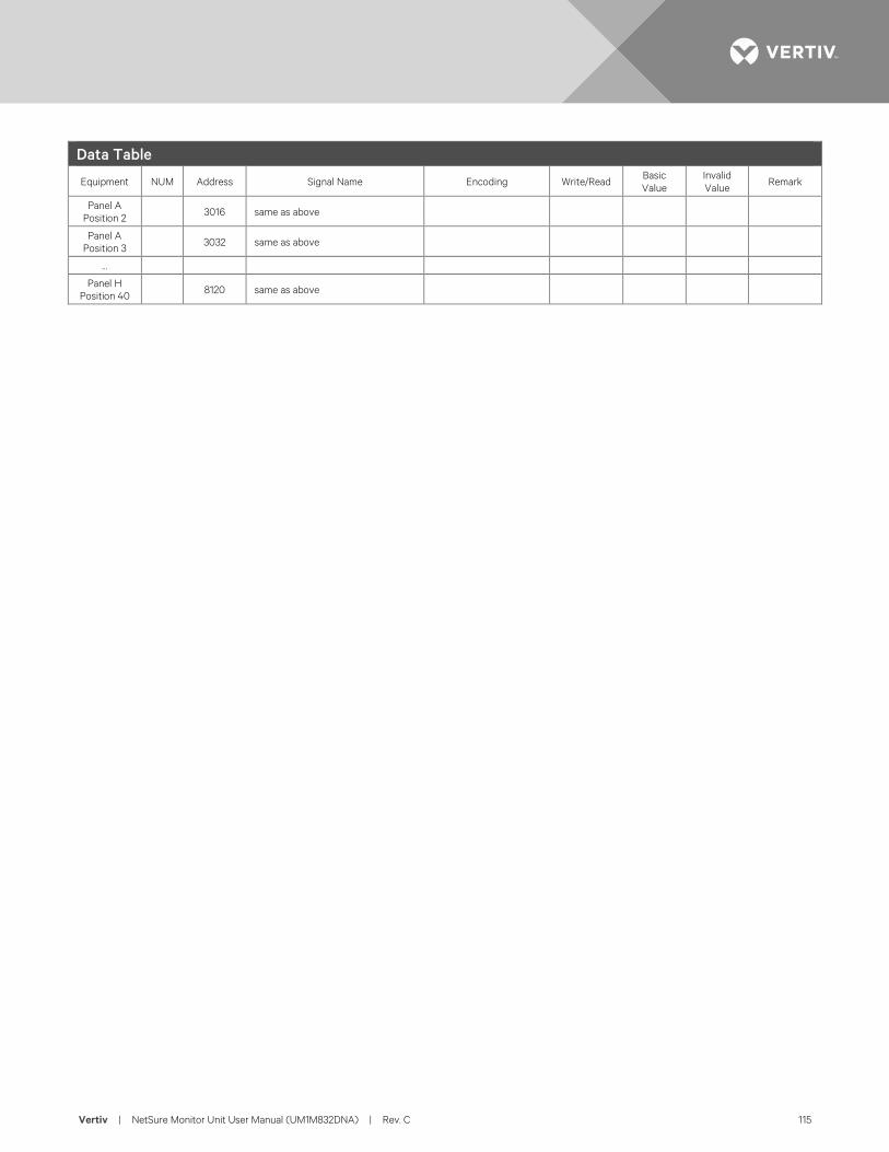
Vertiv | NetSure Monitor Unit User Manual (UM1M832DNA) | Rev. C 115
Data Table
Equipment NUM Address Signal Name Encoding Write/Read Basic Value
Invalid Value Remark
Panel A Position 2
3016 same as above
Panel A Position 3
3032 same as above
…
Panel H Position 40
8120 same as above
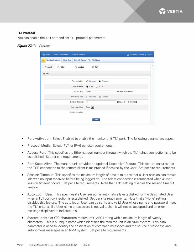
Vertiv | NetSure Monitor Unit User Manual (UM1M832DNA) | Rev. C 116
TL1 Protocol
You can enable the TL1 port and set TL1 protocol parameters.
Figure 77: TL1 Protocol
• Port Activation: Select Enabled to enable the monitor unit TL1 port. The following parameters appear.
• Protocol Media: Select IPV4 or IPV6 per site requirements.
• Access Port: This specifies the Ethernet port number through which the TL1 telnet connection is to be established. Set per site requirements.
• Port Keep-Alive: The monitor unit provides an optional ‘Keep-alive’ feature. This feature ensures that the TCP connection to the remote client is maintained if desired by the User. Set per site requirements.
• Session Timeout: This specifies the maximum length of time in minutes that a User session can remain idle with no input received before being logged off. The telnet connection is terminated when a User session timeout occurs. Set per site requirements. Note that a “0” setting disables the session timeout feature.
• Auto Login User: This specifies if a User session is automatically established for the designated User when a TL1 port connection is established. Set per site requirements. Note that a “None” setting disables this feature. The auto logon User can be set to any valid User whose name and password meet the TL1 criteria. If a User name or password is not valid, then it will not be accepted and an error message displayed to indicate this.
• System Identifier (20 characters maximum): ASCII string with a maximum length of twenty characters. This is a unique name which identifies the monitor unit in an NMA system. This data parameter is used to identify the destination of command messages and the source of response and autonomous messages in an NMA system. Set per site requirements.
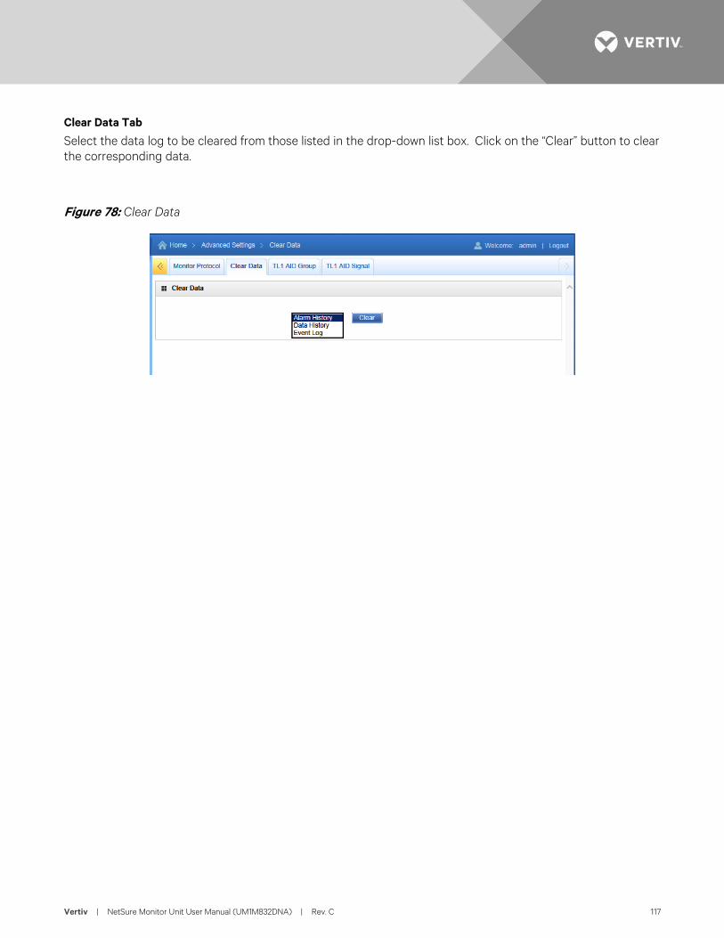
Vertiv | NetSure Monitor Unit User Manual (UM1M832DNA) | Rev. C 117
Clear Data Tab
Select the data log to be cleared from those listed in the drop-down list box. Click on the “Clear” button to clear the corresponding data.
Figure 78: Clear Data
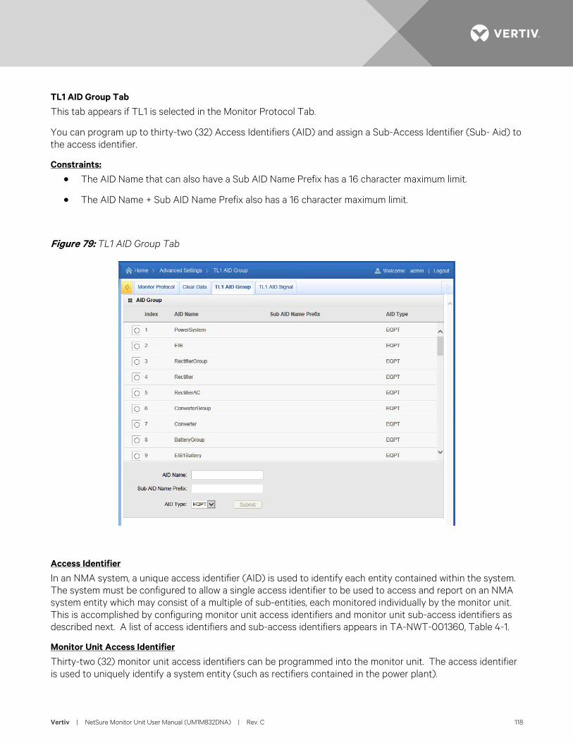
Vertiv | NetSure Monitor Unit User Manual (UM1M832DNA) | Rev. C 118
TL1 AID Group Tab
This tab appears if TL1 is selected in the Monitor Protocol Tab.
You can program up to thirty-two (32) Access Identifiers (AID) and assign a Sub-Access Identifier (Sub- Aid) to the access identifier.
Constraints:
• The AID Name that can also have a Sub AID Name Prefix has a 16 character maximum limit.
• The AID Name + Sub AID Name Prefix also has a 16 character maximum limit.
Figure 79: TL1 AID Group Tab
Access Identifier
In an NMA system, a unique access identifier (AID) is used to identify each entity contained within the system. The system must be configured to allow a single access identifier to be used to access and report on an NMA system entity which may consist of a multiple of sub-entities, each monitored individually by the monitor unit. This is accomplished by configuring monitor unit access identifiers and monitor unit sub-access identifiers as described next. A list of access identifiers and sub-access identifiers appears in TA-NWT-001360, Table 4-1.
Monitor Unit Access Identifier
Thirty-two (32) monitor unit access identifiers can be programmed into the monitor unit. The access identifier is used to uniquely identify a system entity (such as rectifiers contained in the power plant).
Vertiv | NetSure Monitor Unit User Manual (UM1M832DNA) | Rev. C 119
Monitor Unit Sub-Access Identifier
The system sub-access identifiers are used to uniquely identify each sub-entity of an entity (such as each rectifier, each battery string, etc. contained in the power plant). This parameter applies only to TL1 commands/messages. The sub-access identifier identifies a specific sub-entity within an NMA system, such as a specific rectifier. Only alpha-numeric characters can be entered for this parameter. TL1 uses specific values for this parameter. Refer to TA-NWT-001360, Table 4-1.
Procedure
1. Select the Access Identifier (AID) to be programmed by selecting the circle next to its number in the list.
2. Enter an “AID Name” (16 characters maximum). This name represents the AID data parameter used in TL1 commands. Valid characters are limited to alphanumeric characters.
3. Enter a “Sub AID Name Prefix” (if required). This name represents the sub-AID used in TL1 commands. Valid characters are limited to alphanumeric characters. (AID Name + Sub AID Name Prefix 16 characters maximum.)
4. Select an “AID Type”. This entry represents the type modifier used with the AID data parameter in TL1 commands. Identifies the entity represented by this access identifier either as an Equipment type or an Environment type.
• EQPT, refers to equipment entities or entities that are part of the NMA system (ex. battery plants, rectifiers, etc.)
• ENV, refers to environment entities or entities that are external to the NMA system (ex. air conditioners, fans, etc.)
5. Click the submit button.
6. Repeat these steps for the remaining Access Identifiers (AID).
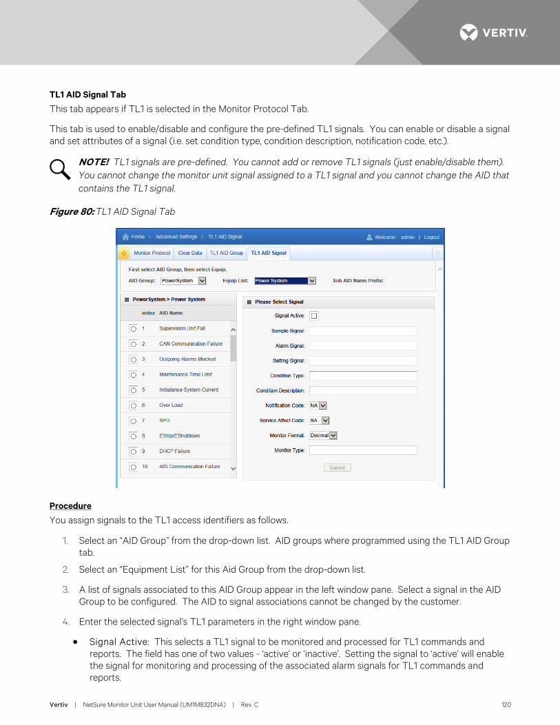
Vertiv | NetSure Monitor Unit User Manual (UM1M832DNA) | Rev. C 120
TL1 AID Signal Tab
This tab appears if TL1 is selected in the Monitor Protocol Tab.
This tab is used to enable/disable and configure the pre-defined TL1 signals. You can enable or disable a signal and set attributes of a signal (i.e. set condition type, condition description, notification code, etc.).
NOTE! TL1 signals are pre-defined. You cannot add or remove TL1 signals (just enable/disable them). You cannot change the monitor unit signal assigned to a TL1 signal and you cannot change the AID that contains the TL1 signal.
Figure 80: TL1 AID Signal Tab
Procedure
You assign signals to the TL1 access identifiers as follows.
1. Select an “AID Group” from the drop-down list. AID groups where programmed using the TL1 AID Group tab.
2. Select an “Equipment List” for this Aid Group from the drop-down list.
3. A list of signals associated to this AID Group appear in the left window pane. Select a signal in the AID Group to be configured. The AID to signal associations cannot be changed by the customer.
4. Enter the selected signal’s TL1 parameters in the right window pane.
• Signal Active: This selects a TL1 signal to be monitored and processed for TL1 commands and reports. The field has one of two values - ‘active’ or ‘inactive’. Setting the signal to ‘active’ will enable the signal for monitoring and processing of the associated alarm signals for TL1 commands and reports.
Vertiv | NetSure Monitor Unit User Manual (UM1M832DNA) | Rev. C 121
• Sample Signal: This is the monitor unit sample signal which is associated to the alarm signal. This signal is used to provide a present value (<monval>) for the TL1 signal (e.g., voltage or temperature reading). This value is used for TL1 commands and reports.
• Alarm Signal: This is the alarm signal whose status is being monitored and reported.
• Setting Signal: This is the monitor unit setting signal which is associated to the alarm signal. This signal is used to provide the threshold (<thlev>) that has been exceeded to generate the alarm causing the change in state of the TL1 signal. This value is used for TL1 reports. This field is only used for alarms associated sample signals which are decimal or integer values (e.g., float, unsigned). It does not apply to signals with enumerated or digital (binary) values.
• Condition Type (20 characters maximum): This is the TL1 text designating the condition corresponding to the alarm. Valid values for this parameter can contain only alphanumeric characters. TL1 uses specific values for this parameter. Refer to TA-NWT-001360 Tables 5-1 through 5-4.
• Condition Description (32 characters maximum): This is a detailed text description or instructions relating to the alarm. Valid values for this parameter can contain only alphanumeric characters. May also be used to describe any action to be taken as a result of the condition.
• Notification Code: This is the TL1 notification code for the associated alarm. It should mirror the alarm severity. Values are CR (critical), MJ, (Major), OB (Observation), NA (Non-alarmed), and NR (Non-reporting).
- CR - Critical Alarm - MJ - Major Alarm - OB - Observation Alarm - NA - Not Alarmed - NR - Not Reported When Event Occurs
• Service Effect Code: This is the TL1 service effect code for this alarm. Values are SA (service affecting) and NSA (Non-Service Affecting).
- SA = service-affecting condition, immediate action required - NSA = nonservice-affecting condition, action required
• Monitor Value Format (I or D): This specifies the format of the monitored value (monval). Values are integer (I) and decimal (D).
• Monitor Type (10 characters maximum): This is the type of parameter being monitored. It should indicate the units of measurement of the sample signal. This field is only used for sample signals that are decimal or integer values (e.g., float, unsigned) and does not apply to signals with enumerated or digital (binary) values. Only alpha characters can be entered for this parameter. TL1 uses specific values for this parameter. Refer to TA-NWT-001360 Table 6-1.
5. Click the Submit button.
6. Repeat these steps for other signals to be added to the AID group and to assign signals to other AID groups.
Vertiv | NetSure Monitor Unit User Manual (UM1M832DNA) | Rev. C 122
ACCESSING THE MONITOR UNIT VIA A NETWORK MANAGEMENT SYSTEM (NMS) General The monitor unit has an SNMP agent function.
Users can use a Network Management System (NMS) to perform the following operations:
• Query the operation status and input/output signals of the devices connected to the monitor unit.
• Browse the active alarms.
When the monitor unit generates alarms, the SNMP agent can be configured to notify the NMS through TRAPS automatically.
NMS Supported by SNMP Agent SNMP is a technology used for network management. The technology is based on implementing an information base called MIB (Managed Information Base). This MIB contains parameters that are of interest from a management perspective. All LAN connected equipment that supports SNMP also supports a default MIB called MIB-II.
The SNMP Agent responds to requests received via the SNMP protocol and also actively sends TRAPS to a specified manager when certain MIB values change state. This is used to actively inform a manager when an alarm situation is recognized.
NMS Supported by SNMP v2 The SNMP agent of the monitor unit supports SNMPv2.
All the NMS that supports SNMPv2c can be used to access the monitor unit. The NMS includes HP OpenView, IBM NetView, Novell ManageWise, SunNet Manager, and so on.
NMS Supported by SNMP v3 The monitor unit has SSL and SNMP V3 function, which makes the monitor unit more powerful and more secure.
With SSL, you can browse/set the Webpage with https. Data is encrypted in the transmission. You can also browse/set the MIB library with SNMP v3. Data is also encrypted in the transmission.
SNMP V3
IE Browser MIB Browser
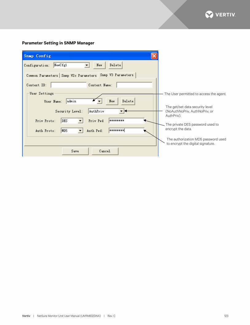
Vertiv | NetSure Monitor Unit User Manual (UM1M832DNA) | Rev. C 123
Parameter Setting in SNMP Manager
The User permitted to access the agent.
The get/set data security level (NoAuthNoPriv, AuthNoPriv, or AuthPriv).
The private DES password used to encrypt the data.
The authorization MD5 password used to encrypt the digital signature.
Vertiv | NetSure Monitor Unit User Manual (UM1M832DNA) | Rev. C 124
MIB Installation Installation The Monitor unit’s MIB is named "Netsure-Distribution.mib". Contact your Vertiv representative for the location on the Web to download the MIB file.
Use the MIB loading function of the NMS to load the MIB database. Refer to the User Manual provided with the NMS for the detailed loading method.
Contents of the Monitor Unit’s MIB The contents of the MIB supported by the monitor unit's SNMP agent and the OID are listed in Table 8. For the details, refer to the MIB file named "Netsure-Monitor Unit.mib".
Accessing the Monitor Unit through an NMS Apply Administrative Privilege In order to use the NMS to manage the devices connected to the monitor unit, the administrative authority needs to be applied for the NMS, that is, add the NMS information to the access list of SNMP agent.
Add NMS through Web Browser
Refer to “NMSV2 Configuration Description (Network Management System)” on page 92 and “NMSV3 Configuration Description (Network Management System)” on page 93 for the method of adding NMS.
EEM Configure The EEM Protocol is used for communication between the Main Computer and the monitor unit. The Main Computer is the computer superior to the monitor unit (the client of the monitor unit). On this page, all parameters needed for communication with a main EEM computer are to be set.
User Information Configuration: On this page, Users, their privilege and password are configured.
Time Synchronization: On this page, the system time and date are to be set.
Automatic time synchronization from time servers can also be configured.
Vertiv | NetSure Monitor Unit User Manual (UM1M832DNA) | Rev. C 125
Table 8: Contents of the Monitor Unit’s MIB
------------------------------------------------------------ -- Distribution MIB ------------------------------------------------------------ POWER-MIB DEFINITIONS ::= BEGIN IMPORTS MODULE-IDENTITY, OBJECT-TYPE, NOTIFICATION-TYPE, Integer32, Counter32, mgmt, enterprises, IpAddress, TimeTicks FROM SNMPv2-SMI TEXTUAL-CONVENTION, DisplayString, DateAndTime FROM SNMPv2-TC; distribMIB MODULE-IDENTITY LAST-UPDATED "201701031042Z" ORGANIZATION " Energy Systems (EES)" CONTACT-INFO " Energy Systems 141 82 Stockholm Sweden" DESCRIPTION " Energy Systems (EES) Distribution MIB, revision A." REVISION "201612201042Z" DESCRIPTION "Initial version" ::= { enterprises 6302 4 1 } stdmib-2 OBJECT IDENTIFIER ::= { mgmt 1 } system OBJECT IDENTIFIER ::= { stdmib-2 1 } sysDescr OBJECT-TYPE SYNTAX DisplayString MAX-ACCESS read-only STATUS current DESCRIPTION " A textual description of the Power System entity. It is formatted as: Network Power - 12VDC Shelf Control Card - product name - SW Vxx.xx.xx - HW Axx - MAC address, where: product name - a string like 1M522B xx.xx.xx - version number like 01.00.00 " ::= { system 1 } sysObjectID OBJECT-TYPE SYNTAX OBJECT IDENTIFIER MAX-ACCESS read-only STATUS current DESCRIPTION " 1.3.6.1.4.1.6302.3.1 which is the base OID for the information in this MIB ." ::= { system 2 } sysUpTime OBJECT-TYPE
Vertiv | NetSure Monitor Unit User Manual (UM1M832DNA) | Rev. C 126
SYNTAX TimeTicks MAX-ACCESS read-only STATUS current DESCRIPTION "The time (in hundredths of a second) since the network management portion of the system was last re-initialized." ::= { system 3 } sysContact OBJECT-TYPE SYNTAX DisplayString (SIZE (0..255)) MAX-ACCESS read-write STATUS current DESCRIPTION "The textual identification of the contact person for this managed node, together with information on how to contact this person." ::= { system 4 } sysName OBJECT-TYPE SYNTAX DisplayString (SIZE (0..255)) MAX-ACCESS read-write STATUS current DESCRIPTION "An administratively-assigned name for this managed node. By convention, this is the node's fully-qualified domain name." ::= { system 5 } sysLocation OBJECT-TYPE SYNTAX DisplayString (SIZE (0..255)) MAX-ACCESS read-write STATUS current DESCRIPTION "The physical location of this node (e.g., `telephone closet, 3rd floor')." ::= { system 6 } sysServices OBJECT-TYPE SYNTAX INTEGER (0..127) MAX-ACCESS read-only STATUS current DESCRIPTION "A value which indicates the set of services that this entity primarily offers. The value is a sum. This sum initially takes the value zero, Then, for each layer, L, in the range 1 through 7, that this node performs transactions for, 2 raised to (L - 1) is added to the sum. For example, a node which performs primarily routing functions would have a value of 4 (2^(3-1)). In contrast, a node which is a host offering application services would have a value of 72 (2^(4-1) + 2^(7-1)). Note that in the context of the Internet suite of protocols, values should be calculated accordingly: layer functionality 1 physical (e.g., repeaters) 2 datalink/subnetwork (e.g., bridges) 3 internet (e.g., IP gateways)
Vertiv | NetSure Monitor Unit User Manual (UM1M832DNA) | Rev. C 127
4 end-to-end (e.g., IP hosts) 7 applications (e.g., mail relays) For systems including OSI protocols, layers 5 and 6 may also be counted." ::= { system 7 } ------------------------------------------------------------ -- Node definitions ------------------------------------------------------------ ees OBJECT IDENTIFIER ::= { enterprises 6302 } global OBJECT IDENTIFIER ::= { ees 4 } ------------------------------------------------------------ -- Textual conventions ------------------------------------------------------------ Status ::= TEXTUAL-CONVENTION STATUS current DESCRIPTION " This integer value represents the operational or administrative status of the system. Also used as alarm severity. Depending on situation there may be limits on allowed values. Operational values: (1) unknown - status has not yet been defined (2) normal - there are no activated alarms (3) warning - OA, lowest level of 'abnormal' status (4) minor - A3 (5) major - MA (6) critical - CA, highest level of 'abnormal' status Administrative values: (7) unmanaged (8) restricted (9) testing (10) disabled" SYNTAX INTEGER { unknown(1), normal(2), warning(3), minor(4), major(5), critical(6), unmanaged(7), restricted(8), testing(9), disabled(10) } StatusChange ::= TEXTUAL-CONVENTION STATUS current DESCRIPTION " Indicates 'activated' (1) or 'deactivated' (2) alarm events." SYNTAX INTEGER { activated(1), deactivated(2) } EnableState ::= TEXTUAL-CONVENTION STATUS current DESCRIPTION " Indicates 'enabled' (0) or 'disabled' (1)" SYNTAX INTEGER {
Vertiv | NetSure Monitor Unit User Manual (UM1M832DNA) | Rev. C 128
enabled(0), disabled(1) } RelayState ::= TEXTUAL-CONVENTION STATUS current DESCRIPTION " Indicates 'off' (0) or 'on' (1)" SYNTAX INTEGER { off(0), on(1) } FACBState ::= TEXTUAL-CONVENTION STATUS current DESCRIPTION " Indicates 'ok' (0) or 'alarm' (1)" SYNTAX INTEGER { ok(0), alarm(1) } PanelTypeOptions ::= TEXTUAL-CONVENTION STATUS current DESCRIPTION " Indicates 'Standard' (0) or 'Advanced' (1)" SYNTAX INTEGER { standard(0), advanced(1) } MeasurementType ::= TEXTUAL-CONVENTION STATUS current DESCRIPTION " Indicates'Hall' (0) or 'Shunt' (1)" SYNTAX INTEGER { hall(0), shunt(1) } PanelPositionNum ::= TEXTUAL-CONVENTION STATUS current DESCRIPTION " Indicates 'two' (0) or 'four' (1) or 'six' (2) or 'eight' (3)" SYNTAX INTEGER { two(0), four(1), six(2), eight(3) } PanelFeedOptions ::= TEXTUAL-CONVENTION STATUS current DESCRIPTION " Indicates 'one' (0) or 'two' (1) or 'three' (2) or 'four' (3) or 'five' (4) or 'six' (5) or 'seven' (6) or 'eigth' (7)" SYNTAX INTEGER { one(0), two(1), three(2), four(3), five(4), six(5), seven(6), eight(7) } panelPositionString ::= TEXTUAL-CONVENTION STATUS current
Vertiv | NetSure Monitor Unit User Manual (UM1M832DNA) | Rev. C 129
DESCRIPTION " Indicates 'a' (0) or 'b' (1) or 'c' (2) or 'd' (3) or 'e' (4) or 'f' (5) or 'g' (6) or 'h' (7)" SYNTAX INTEGER { a(0), b(1), c(2), d(3), e(4), f(5), g(6), h(7) } ClearDataOptions ::= TEXTUAL-CONVENTION STATUS current DESCRIPTION " Indicates 'Clear' (1)" SYNTAX INTEGER { clear(1) } DeviceNumberofBreaker ::= TEXTUAL-CONVENTION STATUS current DESCRIPTION " Indicates 'one' (0) or 'two' (1) or 'three' (2) or 'four' (3) " SYNTAX INTEGER { one(0), two(1), three(2), four(3) } ------------------------------------------------------------ -- 6302.4.1.1 Identification of the plant { distribMIB 1 } ------------------------------------------------------------ ident OBJECT IDENTIFIER ::= { distribMIB 1 } identManufacturer OBJECT-TYPE SYNTAX DisplayString MAX-ACCESS read-only STATUS current DESCRIPTION " The name of the equipment manufacturer." ::= { ident 1 } identModel OBJECT-TYPE SYNTAX DisplayString MAX-ACCESS read-only STATUS current DESCRIPTION " The manufacturers model designation of the controller." ::= { ident 2 } identControllerFirmwareVersion OBJECT-TYPE SYNTAX DisplayString MAX-ACCESS read-only STATUS current DESCRIPTION " The firmware (software) version of the controller." ::= { ident 3 } identName OBJECT-TYPE SYNTAX DisplayString
Vertiv | NetSure Monitor Unit User Manual (UM1M832DNA) | Rev. C 130
MAX-ACCESS read-write STATUS current DESCRIPTION " The name of the distribution bay. This object should be set by the administrator." ::= { ident 4 } identControllerSerialNumber OBJECT-TYPE SYNTAX DisplayString MAX-ACCESS read-only STATUS current DESCRIPTION " The serial number of this controller" ::= { ident 5 } ------------------------------------------------------------ -- 6302.4.1.2 System values { distribMIB 2 } ------------------------------------------------------------ sys OBJECT IDENTIFIER ::= { distribMIB 2 } ------------------------------------------------------------ -- 6302.4.1.2.1 Bay values { system 1 } ------------------------------------------------------------ bay OBJECT IDENTIFIER ::= { sys 1 } baySiteName OBJECT-TYPE SYNTAX DisplayString MAX-ACCESS read-write STATUS current DESCRIPTION " User-provided, 32 characters" ::= { bay 1 } bayTotalCurrentOutput OBJECT-TYPE SYNTAX Integer32 MAX-ACCESS read-only STATUS current DESCRIPTION " Total current (sum of all feeds) in mA " ::= { bay 2 } bayTotalPower OBJECT-TYPE SYNTAX Integer32 MAX-ACCESS read-only STATUS current DESCRIPTION " Output power (sum of all feeds) in Watts " ::= { bay 3 } bayPeakPowerLast24hrs OBJECT-TYPE SYNTAX Integer32 MAX-ACCESS read-only STATUS current DESCRIPTION " Maximum output power over the past 24 hours in Watts " ::= { bay 4 } bayPeakPowerLastWeek OBJECT-TYPE SYNTAX Integer32 MAX-ACCESS read-only STATUS current
Vertiv | NetSure Monitor Unit User Manual (UM1M832DNA) | Rev. C 131
DESCRIPTION " Maximum output power over the past 7 days in Watts " ::= { bay 5 } bayPeakPowerLastMonth OBJECT-TYPE SYNTAX Integer32 MAX-ACCESS read-only STATUS current DESCRIPTION " Maximum output power over the past 30 days in Watts " ::= { bay 6 } bayTotalEnergyLast24hrs OBJECT-TYPE SYNTAX Integer32 MAX-ACCESS read-only STATUS current DESCRIPTION " Total output energy over the past 24 hours in 0.001 kWh " ::= { bay 7 } bayTotalEnergyLastWeek OBJECT-TYPE SYNTAX Integer32 MAX-ACCESS read-only STATUS current DESCRIPTION " Total output energy over the past 7 days in 0.001 kWh " ::= { bay 8 } bayTotalEnergyLastMonth OBJECT-TYPE SYNTAX Integer32 MAX-ACCESS read-only STATUS current DESCRIPTION " Total output energy over the past 30 days in 0.001 kWh" ::= { bay 9 } bayTotalEnergy OBJECT-TYPE SYNTAX Integer32 MAX-ACCESS read-only STATUS current DESCRIPTION " Total/cumulative output energy since last reset, stored as 0.001kWh " ::= { bay 10 } bayRelay1Status OBJECT-TYPE SYNTAX RelayState MAX-ACCESS read-only STATUS current DESCRIPTION " On/Off status of relay 1. 0=off 1=on" ::= { bay 11 } bayRelay2Status OBJECT-TYPE SYNTAX RelayState MAX-ACCESS read-only STATUS current DESCRIPTION " On/Off status of relay 2. 0=off 1=on" ::= { bay 12 } bayRelay3Status OBJECT-TYPE
Vertiv | NetSure Monitor Unit User Manual (UM1M832DNA) | Rev. C 132
SYNTAX RelayState MAX-ACCESS read-only STATUS current DESCRIPTION " On/Off status of relay 3. 0=off 1=on" ::= { bay 13 } bayRelay4Status OBJECT-TYPE SYNTAX RelayState MAX-ACCESS read-only STATUS current DESCRIPTION " On/Off status of relay 4. 0=off 1=on" ::= { bay 14 } bayFACBStatus OBJECT-TYPE SYNTAX FACBState MAX-ACCESS read-only STATUS current DESCRIPTION " FA-CB for all panels in the bay. 0=ok 1=alarm" ::= { bay 15 } bayClearAccumulatedValues OBJECT-TYPE SYNTAX ClearDataOptions MAX-ACCESS read-write STATUS current DESCRIPTION " Used to clear values peak power and total energy, for all accumulated values in this the bay Write 1 to clear values " ::= { bay 16 } bayCurrentBreakerSize OBJECT-TYPE SYNTAX Integer32 MAX-ACCESS read-write STATUS current DESCRIPTION " Rated current for the bay in mA " ::= { bay 17 } bayHighCurrentLimit1 OBJECT-TYPE SYNTAX Integer32 MAX-ACCESS read-write STATUS current DESCRIPTION " Threshold for high current alarm in 0.001 % " ::= { bay 18 } bayHighCurrentLimit2 OBJECT-TYPE SYNTAX Integer32 MAX-ACCESS read-write STATUS current DESCRIPTION " Threshold for high-high current alarm in 0.001 % " ::= { bay 19 } bayNumberOfPanelPositions OBJECT-TYPE SYNTAX PanelPositionNum MAX-ACCESS read-write STATUS current
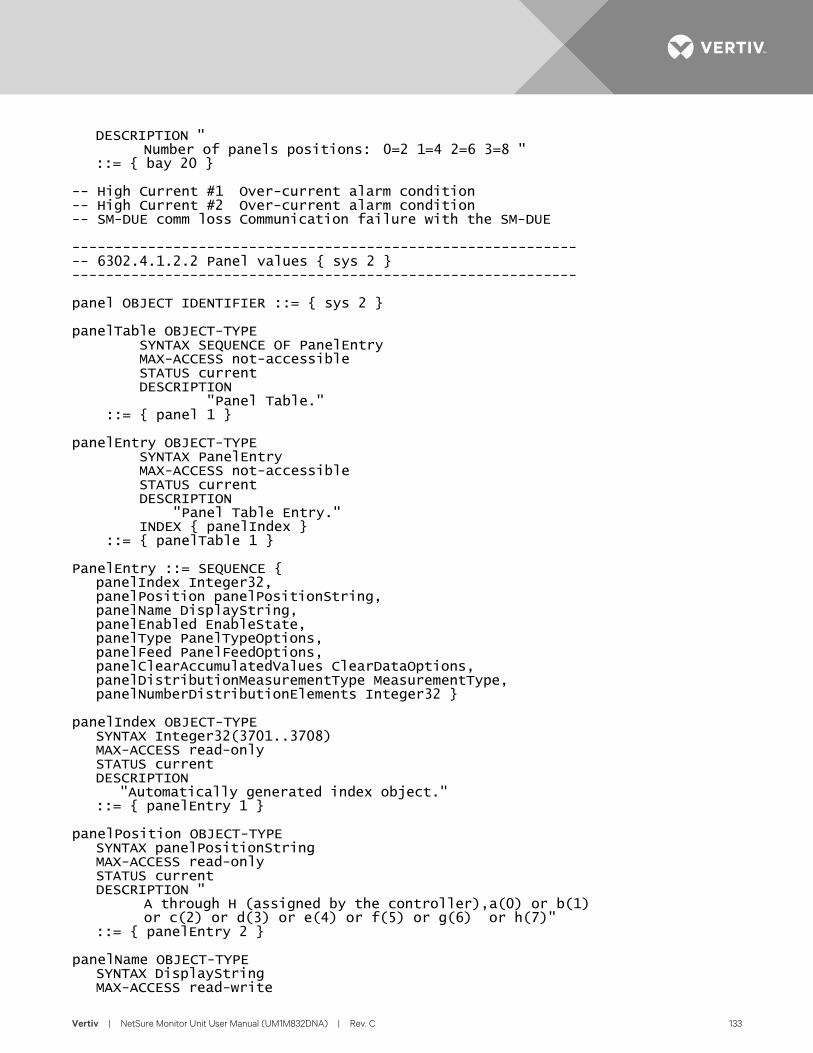
Vertiv | NetSure Monitor Unit User Manual (UM1M832DNA) | Rev. C 133
DESCRIPTION " Number of panels positions: 0=2 1=4 2=6 3=8 " ::= { bay 20 } -- High Current #1 Over-current alarm condition -- High Current #2 Over-current alarm condition -- SM-DUE comm loss Communication failure with the SM-DUE ------------------------------------------------------------ -- 6302.4.1.2.2 Panel values { sys 2 } ------------------------------------------------------------ panel OBJECT IDENTIFIER ::= { sys 2 } panelTable OBJECT-TYPE SYNTAX SEQUENCE OF PanelEntry MAX-ACCESS not-accessible STATUS current DESCRIPTION "Panel Table." ::= { panel 1 } panelEntry OBJECT-TYPE SYNTAX PanelEntry MAX-ACCESS not-accessible STATUS current DESCRIPTION "Panel Table Entry." INDEX { panelIndex } ::= { panelTable 1 } PanelEntry ::= SEQUENCE { panelIndex Integer32, panelPosition panelPositionString, panelName DisplayString, panelEnabled EnableState, panelType PanelTypeOptions, panelFeed PanelFeedOptions, panelClearAccumulatedValues ClearDataOptions, panelDistributionMeasurementType MeasurementType, panelNumberDistributionElements Integer32 } panelIndex OBJECT-TYPE SYNTAX Integer32(3701..3708) MAX-ACCESS read-only STATUS current DESCRIPTION "Automatically generated index object." ::= { panelEntry 1 } panelPosition OBJECT-TYPE SYNTAX panelPositionString MAX-ACCESS read-only STATUS current DESCRIPTION " A through H (assigned by the controller),a(0) or b(1) or c(2) or d(3) or e(4) or f(5) or g(6) or h(7)" ::= { panelEntry 2 } panelName OBJECT-TYPE SYNTAX DisplayString MAX-ACCESS read-write

Vertiv | NetSure Monitor Unit User Manual (UM1M832DNA) | Rev. C 134
STATUS current DESCRIPTION " User-provided, 32 characters" ::= { panelEntry 3 } panelEnabled OBJECT-TYPE SYNTAX EnableState MAX-ACCESS read-write STATUS current DESCRIPTION " Enabled (0) or Disabled (1)" ::= { panelEntry 4 } panelType OBJECT-TYPE SYNTAX PanelTypeOptions MAX-ACCESS read-write STATUS current DESCRIPTION " Standard (0) or Advanced (1)" ::= { panelEntry 5 } panelFeed OBJECT-TYPE SYNTAX PanelFeedOptions MAX-ACCESS read-write STATUS current DESCRIPTION " one(0) or two(1) or three(2) or four(3) or five(4) or six(5) or seven(6) or eigth(7)" ::= { panelEntry 6 } panelClearAccumulatedValues OBJECT-TYPE SYNTAX ClearDataOptions MAX-ACCESS read-write STATUS current DESCRIPTION " Used to clear accumulated values for all distribution devices in this this panel Write 1 to clear values" ::= { panelEntry 7 } panelDistributionMeasurementType OBJECT-TYPE SYNTAX MeasurementType MAX-ACCESS read-write STATUS current DESCRIPTION " Hall (0) or Shunt (1) (advanced panels only)" ::= { panelEntry 8 } panelNumberDistributionElements OBJECT-TYPE SYNTAX Integer32(1..40) MAX-ACCESS read-write STATUS current DESCRIPTION " Number of distributions points in this panel" ::= { panelEntry 9 } -- FA/CB alarm Fuse/circuit-breaker alarm condition -- SM-DUH2 comm loss Communication lost with the SM-DUH2 for this panel ------------------------------------------------------------ -- 6302.4.1.2.3 Feed values { sys 3 } ------------------------------------------------------------
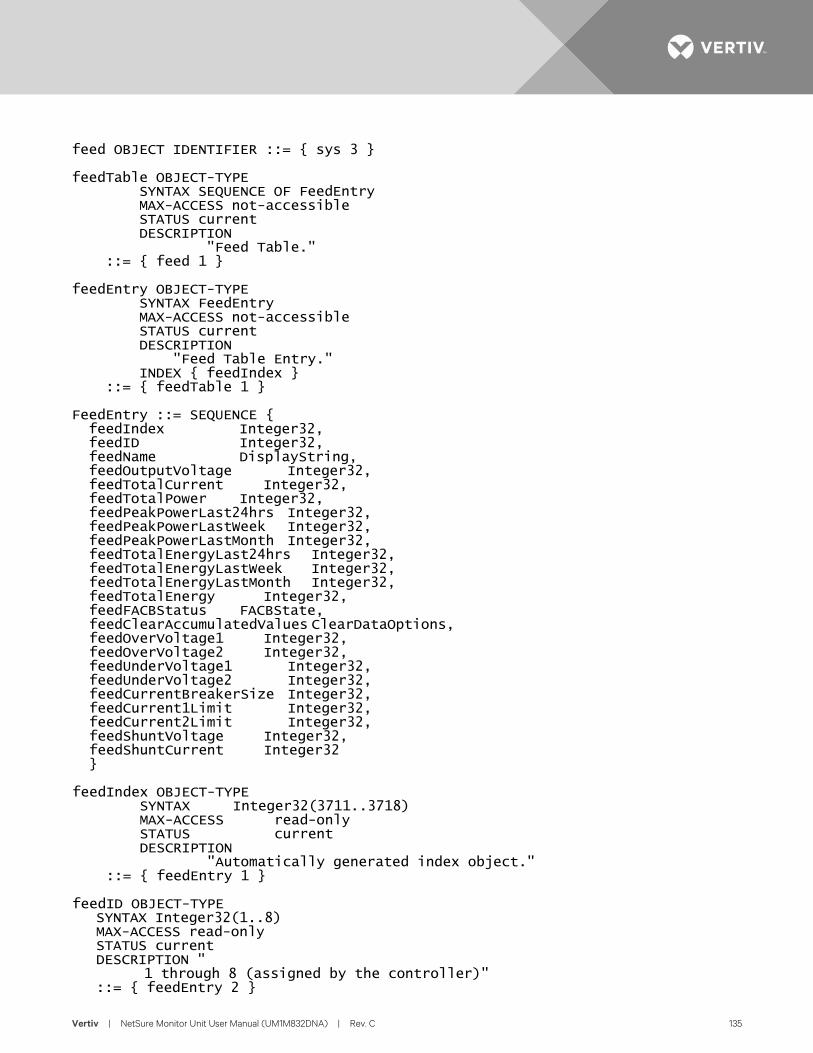
Vertiv | NetSure Monitor Unit User Manual (UM1M832DNA) | Rev. C 135
feed OBJECT IDENTIFIER ::= { sys 3 } feedTable OBJECT-TYPE SYNTAX SEQUENCE OF FeedEntry MAX-ACCESS not-accessible STATUS current DESCRIPTION "Feed Table." ::= { feed 1 } feedEntry OBJECT-TYPE SYNTAX FeedEntry MAX-ACCESS not-accessible STATUS current DESCRIPTION "Feed Table Entry." INDEX { feedIndex } ::= { feedTable 1 } FeedEntry ::= SEQUENCE { feedIndex Integer32, feedID Integer32, feedName DisplayString, feedOutputVoltage Integer32, feedTotalCurrent Integer32, feedTotalPower Integer32, feedPeakPowerLast24hrs Integer32, feedPeakPowerLastWeek Integer32, feedPeakPowerLastMonth Integer32, feedTotalEnergyLast24hrs Integer32, feedTotalEnergyLastWeek Integer32, feedTotalEnergyLastMonth Integer32, feedTotalEnergy Integer32, feedFACBStatus FACBState, feedClearAccumulatedValues ClearDataOptions, feedOverVoltage1 Integer32, feedOverVoltage2 Integer32, feedUnderVoltage1 Integer32, feedUnderVoltage2 Integer32, feedCurrentBreakerSize Integer32, feedCurrent1Limit Integer32, feedCurrent2Limit Integer32, feedShuntVoltage Integer32, feedShuntCurrent Integer32 } feedIndex OBJECT-TYPE SYNTAX Integer32(3711..3718) MAX-ACCESS read-only STATUS current DESCRIPTION "Automatically generated index object." ::= { feedEntry 1 } feedID OBJECT-TYPE SYNTAX Integer32(1..8) MAX-ACCESS read-only STATUS current DESCRIPTION " 1 through 8 (assigned by the controller)" ::= { feedEntry 2 }
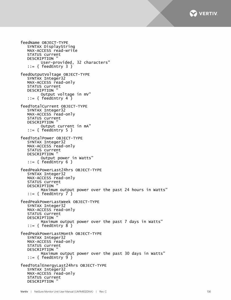
Vertiv | NetSure Monitor Unit User Manual (UM1M832DNA) | Rev. C 136
feedName OBJECT-TYPE SYNTAX DisplayString MAX-ACCESS read-write STATUS current DESCRIPTION " User-provided, 32 characters" ::= { feedEntry 3 } feedOutputVoltage OBJECT-TYPE SYNTAX Integer32 MAX-ACCESS read-only STATUS current DESCRIPTION " Output voltage in mV" ::= { feedEntry 4 } feedTotalCurrent OBJECT-TYPE SYNTAX Integer32 MAX-ACCESS read-only STATUS current DESCRIPTION " Output current in mA" ::= { feedEntry 5 } feedTotalPower OBJECT-TYPE SYNTAX Integer32 MAX-ACCESS read-only STATUS current DESCRIPTION " Output power in Watts" ::= { feedEntry 6 } feedPeakPowerLast24hrs OBJECT-TYPE SYNTAX Integer32 MAX-ACCESS read-only STATUS current DESCRIPTION " Maximum output power over the past 24 hours in Watts" ::= { feedEntry 7 } feedPeakPowerLastWeek OBJECT-TYPE SYNTAX Integer32 MAX-ACCESS read-only STATUS current DESCRIPTION " Maximum output power over the past 7 days in Watts" ::= { feedEntry 8 } feedPeakPowerLastMonth OBJECT-TYPE SYNTAX Integer32 MAX-ACCESS read-only STATUS current DESCRIPTION " Maximum output power over the past 30 days in Watts" ::= { feedEntry 9 } feedTotalEnergyLast24hrs OBJECT-TYPE SYNTAX Integer32 MAX-ACCESS read-only STATUS current DESCRIPTION "
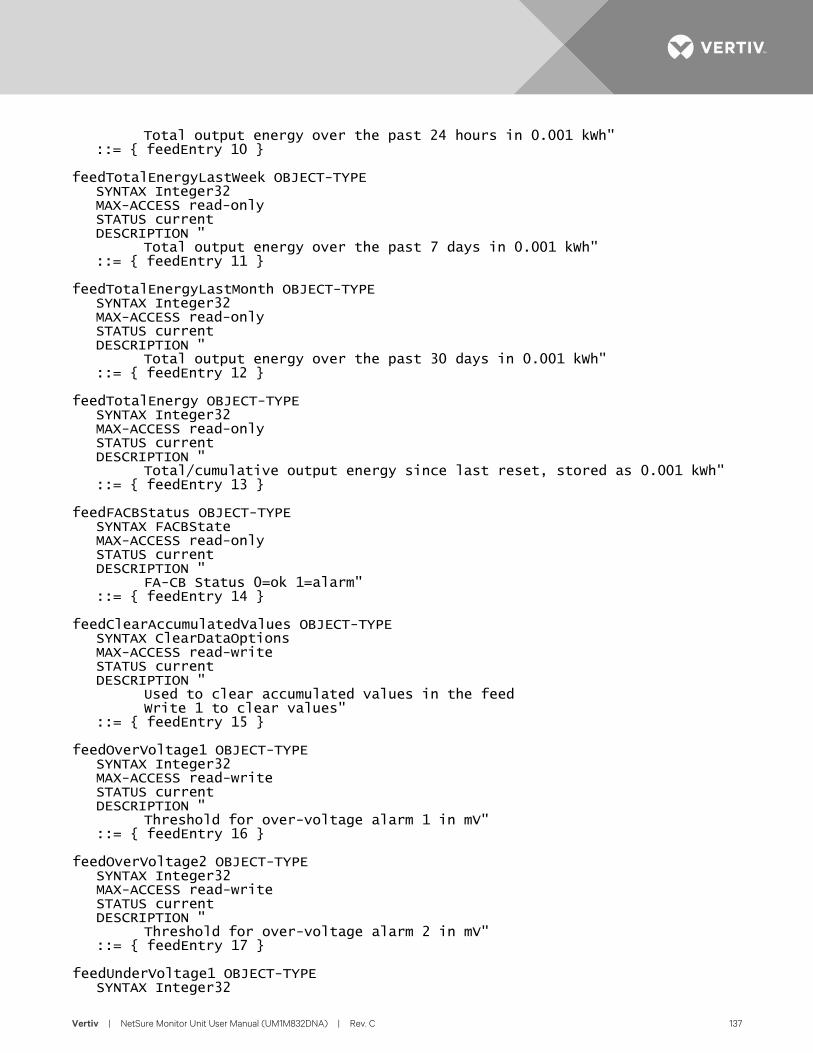
Vertiv | NetSure Monitor Unit User Manual (UM1M832DNA) | Rev. C 137
Total output energy over the past 24 hours in 0.001 kWh" ::= { feedEntry 10 } feedTotalEnergyLastWeek OBJECT-TYPE SYNTAX Integer32 MAX-ACCESS read-only STATUS current DESCRIPTION " Total output energy over the past 7 days in 0.001 kWh" ::= { feedEntry 11 } feedTotalEnergyLastMonth OBJECT-TYPE SYNTAX Integer32 MAX-ACCESS read-only STATUS current DESCRIPTION " Total output energy over the past 30 days in 0.001 kWh" ::= { feedEntry 12 } feedTotalEnergy OBJECT-TYPE SYNTAX Integer32 MAX-ACCESS read-only STATUS current DESCRIPTION " Total/cumulative output energy since last reset, stored as 0.001 kWh" ::= { feedEntry 13 } feedFACBStatus OBJECT-TYPE SYNTAX FACBState MAX-ACCESS read-only STATUS current DESCRIPTION " FA-CB Status 0=ok 1=alarm" ::= { feedEntry 14 } feedClearAccumulatedValues OBJECT-TYPE SYNTAX ClearDataOptions MAX-ACCESS read-write STATUS current DESCRIPTION " Used to clear accumulated values in the feed Write 1 to clear values" ::= { feedEntry 15 } feedOverVoltage1 OBJECT-TYPE SYNTAX Integer32 MAX-ACCESS read-write STATUS current DESCRIPTION " Threshold for over-voltage alarm 1 in mV" ::= { feedEntry 16 } feedOverVoltage2 OBJECT-TYPE SYNTAX Integer32 MAX-ACCESS read-write STATUS current DESCRIPTION " Threshold for over-voltage alarm 2 in mV" ::= { feedEntry 17 } feedUnderVoltage1 OBJECT-TYPE SYNTAX Integer32
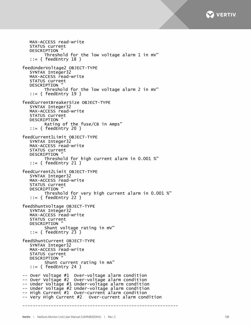
Vertiv | NetSure Monitor Unit User Manual (UM1M832DNA) | Rev. C 138
MAX-ACCESS read-write STATUS current DESCRIPTION " Threshold for the low voltage alarm 1 in mV" ::= { feedEntry 18 } feedUnderVoltage2 OBJECT-TYPE SYNTAX Integer32 MAX-ACCESS read-write STATUS current DESCRIPTION " Threshold for the low voltage alarm 2 in mV" ::= { feedEntry 19 } feedCurrentBreakerSize OBJECT-TYPE SYNTAX Integer32 MAX-ACCESS read-write STATUS current DESCRIPTION " Rating of the fuse/CB in Amps" ::= { feedEntry 20 } feedCurrent1Limit OBJECT-TYPE SYNTAX Integer32 MAX-ACCESS read-write STATUS current DESCRIPTION " Threshold for high current alarm in 0.001 %" ::= { feedEntry 21 } feedCurrent2Limit OBJECT-TYPE SYNTAX Integer32 MAX-ACCESS read-write STATUS current DESCRIPTION " Threshold for very high current alarm in 0.001 %" ::= { feedEntry 22 } feedShuntVoltage OBJECT-TYPE SYNTAX Integer32 MAX-ACCESS read-write STATUS current DESCRIPTION " Shunt voltage rating in mV" ::= { feedEntry 23 } feedShuntCurrent OBJECT-TYPE SYNTAX Integer32 MAX-ACCESS read-write STATUS current DESCRIPTION " Shunt current rating in mA" ::= { feedEntry 24 } -- Over Voltage #1 Over-voltage alarm condition -- Over Voltage #2 Over-voltage alarm condition -- Under Voltage #1 Under-voltage alarm condition -- Under Voltage #2 Under-voltage alarm condition -- High Current #1 Over-current alarm condition -- Very High Current #2 Over-current alarm condition ------------------------------------------------------------
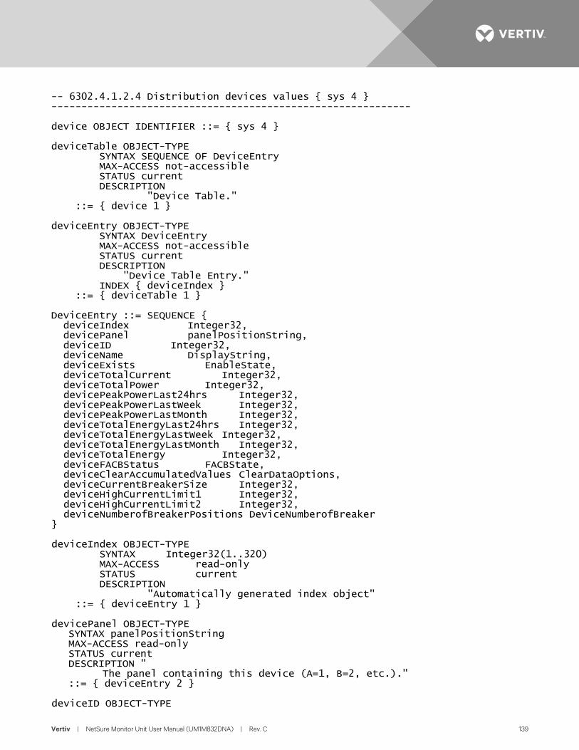
Vertiv | NetSure Monitor Unit User Manual (UM1M832DNA) | Rev. C 139
-- 6302.4.1.2.4 Distribution devices values { sys 4 } ------------------------------------------------------------ device OBJECT IDENTIFIER ::= { sys 4 } deviceTable OBJECT-TYPE SYNTAX SEQUENCE OF DeviceEntry MAX-ACCESS not-accessible STATUS current DESCRIPTION "Device Table." ::= { device 1 } deviceEntry OBJECT-TYPE SYNTAX DeviceEntry MAX-ACCESS not-accessible STATUS current DESCRIPTION "Device Table Entry." INDEX { deviceIndex } ::= { deviceTable 1 } DeviceEntry ::= SEQUENCE { deviceIndex Integer32, devicePanel panelPositionString, deviceID Integer32, deviceName DisplayString, deviceExists EnableState, deviceTotalCurrent Integer32, deviceTotalPower Integer32, devicePeakPowerLast24hrs Integer32, devicePeakPowerLastWeek Integer32, devicePeakPowerLastMonth Integer32, deviceTotalEnergyLast24hrs Integer32, deviceTotalEnergyLastWeek Integer32, deviceTotalEnergyLastMonth Integer32, deviceTotalEnergy Integer32, deviceFACBStatus FACBState, deviceClearAccumulatedValues ClearDataOptions, deviceCurrentBreakerSize Integer32, deviceHighCurrentLimit1 Integer32, deviceHighCurrentLimit2 Integer32, deviceNumberofBreakerPositions DeviceNumberofBreaker } deviceIndex OBJECT-TYPE SYNTAX Integer32(1..320) MAX-ACCESS read-only STATUS current DESCRIPTION "Automatically generated index object" ::= { deviceEntry 1 } devicePanel OBJECT-TYPE SYNTAX panelPositionString MAX-ACCESS read-only STATUS current DESCRIPTION " The panel containing this device (A=1, B=2, etc.)." ::= { deviceEntry 2 } deviceID OBJECT-TYPE

Vertiv | NetSure Monitor Unit User Manual (UM1M832DNA) | Rev. C 140
SYNTAX Integer32(1..40) MAX-ACCESS read-only STATUS current DESCRIPTION " The distribution device's ID/position" ::= { deviceEntry 3 } deviceName OBJECT-TYPE SYNTAX DisplayString MAX-ACCESS read-write STATUS current DESCRIPTION " User-provided, 32 characters" ::= { deviceEntry 4 } deviceExists OBJECT-TYPE SYNTAX EnableState MAX-ACCESS read-write STATUS current DESCRIPTION " Used (0) or not Used (1)" ::= { deviceEntry 5 } deviceTotalCurrent OBJECT-TYPE SYNTAX Integer32 MAX-ACCESS read-only STATUS current DESCRIPTION " Total output current in mA" ::= { deviceEntry 6 } deviceTotalPower OBJECT-TYPE SYNTAX Integer32 MAX-ACCESS read-only STATUS current DESCRIPTION " Total output power in Watts" ::= { deviceEntry 7 } devicePeakPowerLast24hrs OBJECT-TYPE SYNTAX Integer32 MAX-ACCESS read-only STATUS current DESCRIPTION " Maximum output power over the past 24 hours in Watts" ::= { deviceEntry 8 } devicePeakPowerLastWeek OBJECT-TYPE SYNTAX Integer32 MAX-ACCESS read-only STATUS current DESCRIPTION " Maximum output power over the past 7 days in Watts" ::= { deviceEntry 9 } devicePeakPowerLastMonth OBJECT-TYPE SYNTAX Integer32 MAX-ACCESS read-only STATUS current DESCRIPTION " Maximum output power over the past 30 days in Watts" ::= { deviceEntry 10 }
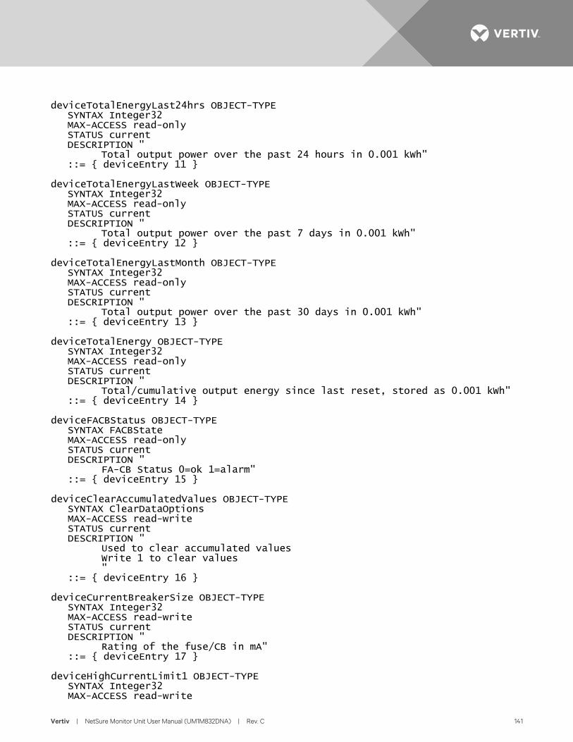
Vertiv | NetSure Monitor Unit User Manual (UM1M832DNA) | Rev. C 141
deviceTotalEnergyLast24hrs OBJECT-TYPE SYNTAX Integer32 MAX-ACCESS read-only STATUS current DESCRIPTION " Total output power over the past 24 hours in 0.001 kWh" ::= { deviceEntry 11 } deviceTotalEnergyLastWeek OBJECT-TYPE SYNTAX Integer32 MAX-ACCESS read-only STATUS current DESCRIPTION " Total output power over the past 7 days in 0.001 kWh" ::= { deviceEntry 12 } deviceTotalEnergyLastMonth OBJECT-TYPE SYNTAX Integer32 MAX-ACCESS read-only STATUS current DESCRIPTION " Total output power over the past 30 days in 0.001 kWh" ::= { deviceEntry 13 } deviceTotalEnergy OBJECT-TYPE SYNTAX Integer32 MAX-ACCESS read-only STATUS current DESCRIPTION " Total/cumulative output energy since last reset, stored as 0.001 kWh" ::= { deviceEntry 14 } deviceFACBStatus OBJECT-TYPE SYNTAX FACBState MAX-ACCESS read-only STATUS current DESCRIPTION " FA-CB Status 0=ok 1=alarm" ::= { deviceEntry 15 } deviceClearAccumulatedValues OBJECT-TYPE SYNTAX ClearDataOptions MAX-ACCESS read-write STATUS current DESCRIPTION " Used to clear accumulated values Write 1 to clear values " ::= { deviceEntry 16 } deviceCurrentBreakerSize OBJECT-TYPE SYNTAX Integer32 MAX-ACCESS read-write STATUS current DESCRIPTION " Rating of the fuse/CB in mA" ::= { deviceEntry 17 } deviceHighCurrentLimit1 OBJECT-TYPE SYNTAX Integer32 MAX-ACCESS read-write
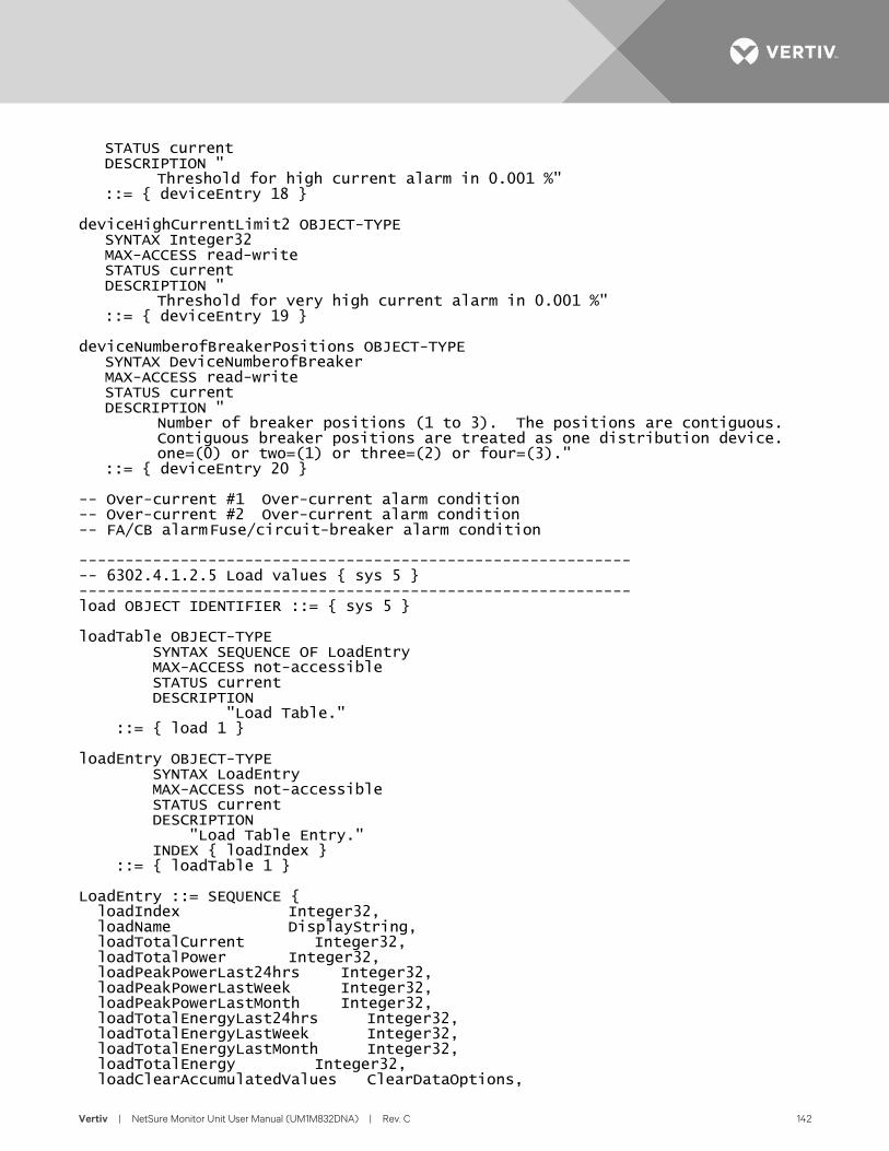
Vertiv | NetSure Monitor Unit User Manual (UM1M832DNA) | Rev. C 142
STATUS current DESCRIPTION " Threshold for high current alarm in 0.001 %" ::= { deviceEntry 18 } deviceHighCurrentLimit2 OBJECT-TYPE SYNTAX Integer32 MAX-ACCESS read-write STATUS current DESCRIPTION " Threshold for very high current alarm in 0.001 %" ::= { deviceEntry 19 } deviceNumberofBreakerPositions OBJECT-TYPE SYNTAX DeviceNumberofBreaker MAX-ACCESS read-write STATUS current DESCRIPTION " Number of breaker positions (1 to 3). The positions are contiguous. Contiguous breaker positions are treated as one distribution device. one=(0) or two=(1) or three=(2) or four=(3)." ::= { deviceEntry 20 } -- Over-current #1 Over-current alarm condition -- Over-current #2 Over-current alarm condition -- FA/CB alarm Fuse/circuit-breaker alarm condition ------------------------------------------------------------ -- 6302.4.1.2.5 Load values { sys 5 } ------------------------------------------------------------ load OBJECT IDENTIFIER ::= { sys 5 } loadTable OBJECT-TYPE SYNTAX SEQUENCE OF LoadEntry MAX-ACCESS not-accessible STATUS current DESCRIPTION "Load Table." ::= { load 1 } loadEntry OBJECT-TYPE SYNTAX LoadEntry MAX-ACCESS not-accessible STATUS current DESCRIPTION "Load Table Entry." INDEX { loadIndex } ::= { loadTable 1 } LoadEntry ::= SEQUENCE { loadIndex Integer32, loadName DisplayString, loadTotalCurrent Integer32, loadTotalPower Integer32, loadPeakPowerLast24hrs Integer32, loadPeakPowerLastWeek Integer32, loadPeakPowerLastMonth Integer32, loadTotalEnergyLast24hrs Integer32, loadTotalEnergyLastWeek Integer32, loadTotalEnergyLastMonth Integer32, loadTotalEnergy Integer32, loadClearAccumulatedValues ClearDataOptions,
Vertiv | NetSure Monitor Unit User Manual (UM1M832DNA) | Rev. C 143
loadMaximumCurrent Integer32, loadHighCurrentLimit1 Integer32, loadHighCurrentLimit2 Integer32 } loadIndex OBJECT-TYPE SYNTAX Integer32 MAX-ACCESS read-only STATUS current DESCRIPTION "Automatically generated index object." ::= { loadEntry 1 } loadName OBJECT-TYPE SYNTAX DisplayString MAX-ACCESS read-write STATUS current DESCRIPTION " User-provided, 32 characters" ::= { loadEntry 2 } loadTotalCurrent OBJECT-TYPE SYNTAX Integer32 MAX-ACCESS read-only STATUS current DESCRIPTION " Total output current in mA" ::= { loadEntry 3 } loadTotalPower OBJECT-TYPE SYNTAX Integer32 MAX-ACCESS read-only STATUS current DESCRIPTION " Total output power in Watts" ::= { loadEntry 4 } loadPeakPowerLast24hrs OBJECT-TYPE SYNTAX Integer32 MAX-ACCESS read-only STATUS current DESCRIPTION " Maximum output power over the past 24 hours in Watts" ::= { loadEntry 5 } loadPeakPowerLastWeek OBJECT-TYPE SYNTAX Integer32 MAX-ACCESS read-only STATUS current DESCRIPTION " Maximum output power over the past 7 days in Watts" ::= { loadEntry 6 } loadPeakPowerLastMonth OBJECT-TYPE SYNTAX Integer32 MAX-ACCESS read-only STATUS current DESCRIPTION " Maximum output power over the past 30 days in Watts" ::= { loadEntry 7 } loadTotalEnergyLast24hrs OBJECT-TYPE
Vertiv | NetSure Monitor Unit User Manual (UM1M832DNA) | Rev. C 144
SYNTAX Integer32 MAX-ACCESS read-only STATUS current DESCRIPTION " Total output power over the past 24 hours in 0.001 kWh" ::= { loadEntry 8 } loadTotalEnergyLastWeek OBJECT-TYPE SYNTAX Integer32 MAX-ACCESS read-only STATUS current DESCRIPTION " Total output power over the past 7 days in 0.001 kWh" ::= { loadEntry 9 } loadTotalEnergyLastMonth OBJECT-TYPE SYNTAX Integer32 MAX-ACCESS read-only STATUS current DESCRIPTION " Total output power over the past 30 days in 0.001 kWh" ::= { loadEntry 10 } loadTotalEnergy OBJECT-TYPE SYNTAX Integer32 MAX-ACCESS read-only STATUS current DESCRIPTION " Total/cumulative output energy since last reset in 0.001 kWh" ::= { loadEntry 11 } loadClearAccumulatedValues OBJECT-TYPE SYNTAX ClearDataOptions MAX-ACCESS read-write STATUS current DESCRIPTION " Used to clear accumulated values Write 1 value to clear values " ::= { loadEntry 12 } loadMaximumCurrent OBJECT-TYPE SYNTAX Integer32 MAX-ACCESS read-write STATUS current DESCRIPTION " Maximum current in amps for the load; the total current is never expected to exceed this value" ::= { loadEntry 13 } loadHighCurrentLimit1 OBJECT-TYPE SYNTAX Integer32 MAX-ACCESS read-write STATUS current DESCRIPTION " Threshold for high current alarm in 0.001 %" ::= { loadEntry 14 } loadHighCurrentLimit2 OBJECT-TYPE SYNTAX Integer32 MAX-ACCESS read-write STATUS current
Vertiv | NetSure Monitor Unit User Manual (UM1M832DNA) | Rev. C 145
DESCRIPTION " Threshold for very high current alarm in 0.001 %" ::= { loadEntry 15 } -- Over-current #1 Over-current alarm condition -- Over-current #2 Over-current alarm condition ------------------------------------------------------------ -- Alarm trap counter { distribMIB 3 } ------------------------------------------------------------ alarmLastTrapNo OBJECT-TYPE SYNTAX Counter32 MAX-ACCESS read-only STATUS current DESCRIPTION " The sequence number of last submitted alarm trap, also last row in alarmTrapTable." ::= { distribMIB 3 } ------------------------------------------------------------ -- Active Alarm table { distribMIB 4 } ------------------------------------------------------------ alarmActiveAlarmTable OBJECT-TYPE SYNTAX SEQUENCE OF ActiveAlarmEntry MAX-ACCESS not-accessible STATUS current DESCRIPTION " Table holding information about the currently active alarms." ::= { distribMIB 4 } activeAlarmEntry OBJECT-TYPE SYNTAX ActiveAlarmEntry MAX-ACCESS not-accessible STATUS current DESCRIPTION " An entry (conceptual row) in the alarmTrapTable." INDEX { alarmIndex } ::= { alarmActiveAlarmTable 1 } ActiveAlarmEntry ::= SEQUENCE { alarmIndex Counter32, alarmTime DateAndTime, alarmStatusChange StatusChange, alarmSeverity Status, alarmDescription DisplayString, alarmType Integer32 } alarmIndex OBJECT-TYPE SYNTAX Counter32 MAX-ACCESS read-only STATUS current DESCRIPTION " The unique sequence number of this alarm trap." ::= { activeAlarmEntry 1 } alarmTime OBJECT-TYPE SYNTAX DateAndTime MAX-ACCESS read-only STATUS current DESCRIPTION "
Vertiv | NetSure Monitor Unit User Manual (UM1M832DNA) | Rev. C 146
Date and time when event occured (local time), including timezone if supported by controller." ::= { activeAlarmEntry 2 } alarmStatusChange OBJECT-TYPE SYNTAX StatusChange MAX-ACCESS read-only STATUS current DESCRIPTION " The type of alarm change. One of (1) activated (2) deactivated" ::= { activeAlarmEntry 3 } alarmSeverity OBJECT-TYPE SYNTAX Status MAX-ACCESS read-only STATUS current DESCRIPTION " The severity of the alarm. One of (3) warning - OA, lowest level of alarm severity (4) minor - A3 (5) major - MA (6) critical - CA, highest level of alarm severity" ::= { activeAlarmEntry 4 } alarmDescription OBJECT-TYPE SYNTAX DisplayString MAX-ACCESS read-only STATUS current DESCRIPTION " Free-text description of alarm." ::= { activeAlarmEntry 5 } alarmType OBJECT-TYPE SYNTAX Integer32 MAX-ACCESS read-only STATUS current DESCRIPTION " Alarm type, i.e. an integer specifying the type of alarm." ::= { activeAlarmEntry 6 } ------------------------------------------------------------ -- Events/traps { distribMIB 5 } ------------------------------------------------------------ powerEvents OBJECT IDENTIFIER ::= { distribMIB 5 } alarmTrap NOTIFICATION-TYPE OBJECTS { alarmIndex, alarmTime, alarmStatusChange, alarmSeverity, alarmDescription, alarmType } STATUS current DESCRIPTION " An alarm trap is sent when an alarm occurs (activated) or returns to normal state (deactivated). Alarm traps are logged in alarmTrapTable. Variables in this trap: * alarmIndex - The unique sequence number of this alarm trap.
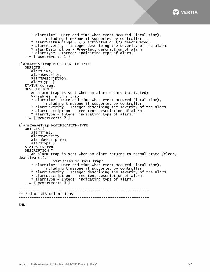
Vertiv | NetSure Monitor Unit User Manual (UM1M832DNA) | Rev. C 147
* alarmTime - Date and time when event occured (local time), including timezone if supported by controller. * alarmStatusChange - (1) activated or (2) deactivated. * alarmSeverity - Integer describing the severity of the alarm. * alarmDescription - Free-text description of alarm. * alarmType - Integer indicating type of alarm." ::= { powerEvents 1 } alarmActiveTrap NOTIFICATION-TYPE OBJECTS { alarmTime, alarmSeverity, alarmDescription, alarmType } STATUS current DESCRIPTION " An alarm trap is sent when an alarm occurs (activated) Variables in this trap * alarmTime - Date and time when event occured (local time), including timezone if supported by controller. * alarmSeverity - Integer describing the severity of the alarm. * alarmDescription - Free-text description of alarm. * alarmType - Integer indicating type of alarm." ::= { powerEvents 2 } alarmCeaseTrap NOTIFICATION-TYPE OBJECTS { alarmTime, alarmSeverity, alarmDescription, alarmType } STATUS current DESCRIPTION " An alarm trap is sent when an alarm returns to normal state (clear, deactivated). Variables in this trap: * alarmTime - Date and time when event occured (local time), including timezone if supported by controller. * alarmSeverity - Integer describing the severity of the alarm. * alarmDescription - Free-text description of alarm. * alarmType - Integer indicating type of alarm." ::= { powerEvents 3 } ------------------------------------------------------------ -- End of MIB definitions ------------------------------------------------------------ END
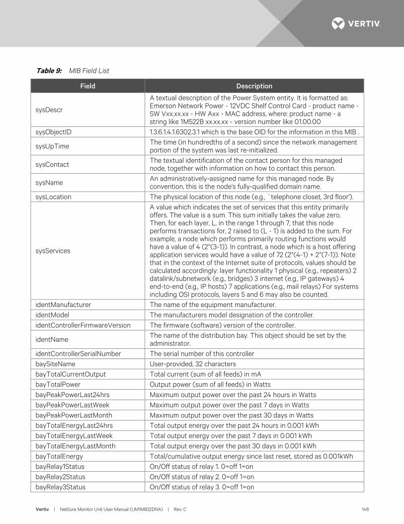
Vertiv | NetSure Monitor Unit User Manual (UM1M832DNA) | Rev. C 148
Table 9: MIB Field List
Field Description
sysDescr
A textual description of the Power System entity. It is formatted as: Emerson Network Power - 12VDC Shelf Control Card - product name - SW Vxx.xx.xx - HW Axx - MAC address, where: product name - a string like 1M522B xx.xx.xx - version number like 01.00.00
sysObjectID 1.3.6.1.4.1.6302.3.1 which is the base OID for the information in this MIB .
sysUpTime The time (in hundredths of a second) since the network management portion of the system was last re-initialized.
sysContact The textual identification of the contact person for this managed node, together with information on how to contact this person.
sysName An administratively-assigned name for this managed node. By convention, this is the node's fully-qualified domain name.
sysLocation The physical location of this node (e.g., `telephone closet, 3rd floor').
sysServices
A value which indicates the set of services that this entity primarily offers. The value is a sum. This sum initially takes the value zero, Then, for each layer, L, in the range 1 through 7, that this node performs transactions for, 2 raised to (L - 1) is added to the sum. For example, a node which performs primarily routing functions would have a value of 4 (2^(3-1)). In contrast, a node which is a host offering application services would have a value of 72 (2^(4-1) + 2^(7-1)). Note that in the context of the Internet suite of protocols, values should be calculated accordingly: layer functionality 1 physical (e.g., repeaters) 2 datalink/subnetwork (e.g., bridges) 3 internet (e.g., IP gateways) 4 end-to-end (e.g., IP hosts) 7 applications (e.g., mail relays) For systems including OSI protocols, layers 5 and 6 may also be counted.
identManufacturer The name of the equipment manufacturer. identModel The manufacturers model designation of the controller. identControllerFirmwareVersion The firmware (software) version of the controller.
identName The name of the distribution bay. This object should be set by the administrator.
identControllerSerialNumber The serial number of this controller baySiteName User-provided, 32 characters bayTotalCurrentOutput Total current (sum of all feeds) in mA bayTotalPower Output power (sum of all feeds) in Watts bayPeakPowerLast24hrs Maximum output power over the past 24 hours in Watts bayPeakPowerLastWeek Maximum output power over the past 7 days in Watts bayPeakPowerLastMonth Maximum output power over the past 30 days in Watts bayTotalEnergyLast24hrs Total output energy over the past 24 hours in 0.001 kWh bayTotalEnergyLastWeek Total output energy over the past 7 days in 0.001 kWh bayTotalEnergyLastMonth Total output energy over the past 30 days in 0.001 kWh bayTotalEnergy Total/cumulative output energy since last reset, stored as 0.001kWh bayRelay1Status On/Off status of relay 1. 0=off 1=on bayRelay2Status On/Off status of relay 2. 0=off 1=on bayRelay3Status On/Off status of relay 3. 0=off 1=on
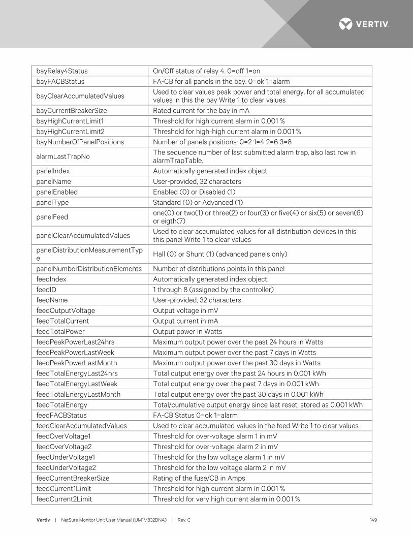
Vertiv | NetSure Monitor Unit User Manual (UM1M832DNA) | Rev. C 149
bayRelay4Status On/Off status of relay 4. 0=off 1=on bayFACBStatus FA-CB for all panels in the bay. 0=ok 1=alarm
bayClearAccumulatedValues Used to clear values peak power and total energy, for all accumulated values in this the bay Write 1 to clear values
bayCurrentBreakerSize Rated current for the bay in mA bayHighCurrentLimit1 Threshold for high current alarm in 0.001 % bayHighCurrentLimit2 Threshold for high-high current alarm in 0.001 % bayNumberOfPanelPositions Number of panels positions: 0=2 1=4 2=6 3=8
alarmLastTrapNo The sequence number of last submitted alarm trap, also last row in alarmTrapTable.
panelIndex Automatically generated index object. panelName User-provided, 32 characters panelEnabled Enabled (0) or Disabled (1) panelType Standard (0) or Advanced (1)
panelFeed one(0) or two(1) or three(2) or four(3) or five(4) or six(5) or seven(6) or eigth(7)
panelClearAccumulatedValues Used to clear accumulated values for all distribution devices in this this panel Write 1 to clear values
panelDistributionMeasurementType Hall (0) or Shunt (1) (advanced panels only)
panelNumberDistributionElements Number of distributions points in this panel feedIndex Automatically generated index object. feedID 1 through 8 (assigned by the controller) feedName User-provided, 32 characters feedOutputVoltage Output voltage in mV feedTotalCurrent Output current in mA feedTotalPower Output power in Watts feedPeakPowerLast24hrs Maximum output power over the past 24 hours in Watts feedPeakPowerLastWeek Maximum output power over the past 7 days in Watts feedPeakPowerLastMonth Maximum output power over the past 30 days in Watts feedTotalEnergyLast24hrs Total output energy over the past 24 hours in 0.001 kWh feedTotalEnergyLastWeek Total output energy over the past 7 days in 0.001 kWh feedTotalEnergyLastMonth Total output energy over the past 30 days in 0.001 kWh feedTotalEnergy Total/cumulative output energy since last reset, stored as 0.001 kWh feedFACBStatus FA-CB Status 0=ok 1=alarm feedClearAccumulatedValues Used to clear accumulated values in the feed Write 1 to clear values feedOverVoltage1 Threshold for over-voltage alarm 1 in mV feedOverVoltage2 Threshold for over-voltage alarm 2 in mV feedUnderVoltage1 Threshold for the low voltage alarm 1 in mV feedUnderVoltage2 Threshold for the low voltage alarm 2 in mV feedCurrentBreakerSize Rating of the fuse/CB in Amps feedCurrent1Limit Threshold for high current alarm in 0.001 % feedCurrent2Limit Threshold for very high current alarm in 0.001 %
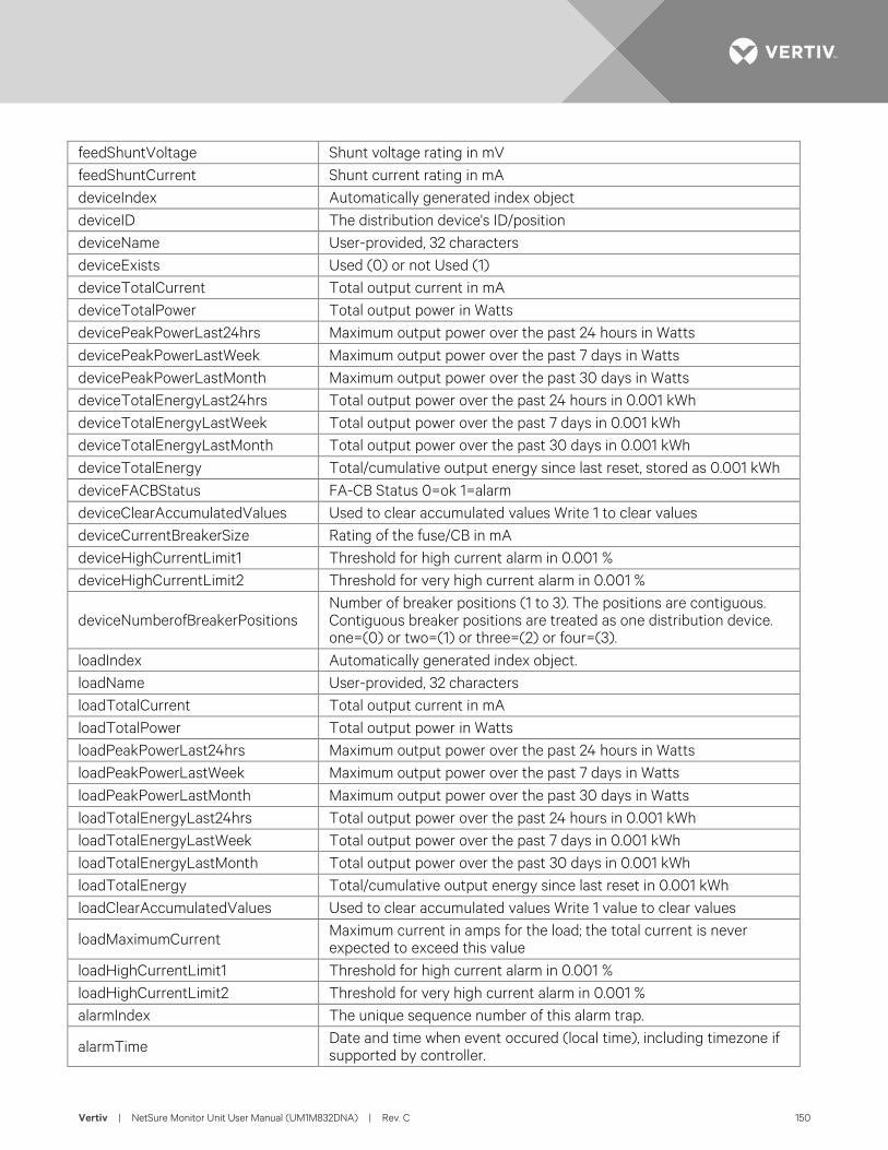
Vertiv | NetSure Monitor Unit User Manual (UM1M832DNA) | Rev. C 150
feedShuntVoltage Shunt voltage rating in mV feedShuntCurrent Shunt current rating in mA deviceIndex Automatically generated index object deviceID The distribution device's ID/position deviceName User-provided, 32 characters deviceExists Used (0) or not Used (1) deviceTotalCurrent Total output current in mA deviceTotalPower Total output power in Watts devicePeakPowerLast24hrs Maximum output power over the past 24 hours in Watts devicePeakPowerLastWeek Maximum output power over the past 7 days in Watts devicePeakPowerLastMonth Maximum output power over the past 30 days in Watts deviceTotalEnergyLast24hrs Total output power over the past 24 hours in 0.001 kWh deviceTotalEnergyLastWeek Total output power over the past 7 days in 0.001 kWh deviceTotalEnergyLastMonth Total output power over the past 30 days in 0.001 kWh deviceTotalEnergy Total/cumulative output energy since last reset, stored as 0.001 kWh deviceFACBStatus FA-CB Status 0=ok 1=alarm deviceClearAccumulatedValues Used to clear accumulated values Write 1 to clear values deviceCurrentBreakerSize Rating of the fuse/CB in mA deviceHighCurrentLimit1 Threshold for high current alarm in 0.001 % deviceHighCurrentLimit2 Threshold for very high current alarm in 0.001 %
deviceNumberofBreakerPositions Number of breaker positions (1 to 3). The positions are contiguous. Contiguous breaker positions are treated as one distribution device. one=(0) or two=(1) or three=(2) or four=(3).
loadIndex Automatically generated index object. loadName User-provided, 32 characters loadTotalCurrent Total output current in mA loadTotalPower Total output power in Watts loadPeakPowerLast24hrs Maximum output power over the past 24 hours in Watts loadPeakPowerLastWeek Maximum output power over the past 7 days in Watts loadPeakPowerLastMonth Maximum output power over the past 30 days in Watts loadTotalEnergyLast24hrs Total output power over the past 24 hours in 0.001 kWh loadTotalEnergyLastWeek Total output power over the past 7 days in 0.001 kWh loadTotalEnergyLastMonth Total output power over the past 30 days in 0.001 kWh loadTotalEnergy Total/cumulative output energy since last reset in 0.001 kWh loadClearAccumulatedValues Used to clear accumulated values Write 1 value to clear values
loadMaximumCurrent Maximum current in amps for the load; the total current is never expected to exceed this value
loadHighCurrentLimit1 Threshold for high current alarm in 0.001 % loadHighCurrentLimit2 Threshold for very high current alarm in 0.001 % alarmIndex The unique sequence number of this alarm trap.
alarmTime Date and time when event occured (local time), including timezone if supported by controller.
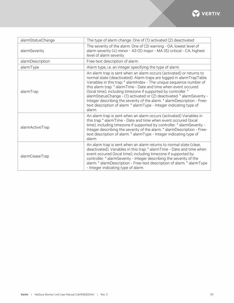
Vertiv | NetSure Monitor Unit User Manual (UM1M832DNA) | Rev. C 151
alarmStatusChange The type of alarm change. One of (1) activated (2) deactivated
alarmSeverity The severity of the alarm. One of (3) warning - OA, lowest level of alarm severity (4) minor - A3 (5) major - MA (6) critical - CA, highest level of alarm severity
alarmDescription Free-text description of alarm. alarmType Alarm type, i.e. an integer specifying the type of alarm.
alarmTrap
An alarm trap is sent when an alarm occurs (activated) or returns to normal state (deactivated). Alarm traps are logged in alarmTrapTable. Variables in this trap: * alarmIndex - The unique sequence number of this alarm trap. * alarmTime - Date and time when event occured (local time), including timezone if supported by controller. * alarmStatusChange - (1) activated or (2) deactivated. * alarmSeverity - Integer describing the severity of the alarm. * alarmDescription - Free-text description of alarm. * alarmType - Integer indicating type of alarm.
alarmActiveTrap
An alarm trap is sent when an alarm occurs (activated) Variables in this trap * alarmTime - Date and time when event occured (local time), including timezone if supported by controller. * alarmSeverity - Integer describing the severity of the alarm. * alarmDescription - Free-text description of alarm. * alarmType - Integer indicating type of alarm.
alarmCeaseTrap
An alarm trap is sent when an alarm returns to normal state (clear, deactivated). Variables in this trap: * alarmTime - Date and time when event occured (local time), including timezone if supported by controller. * alarmSeverity - Integer describing the severity of the alarm. * alarmDescription - Free-text description of alarm. * alarmType - Integer indicating type of alarm.
Vertiv | NetSure Monitor Unit User Manual (UM1M832DNA) | Rev. C 152
ACCESSING THE MONITOR UNIT VIA TL1 Accessing the TL1 Port Port Connection
• Connection to the TL1 interface is made through the monitor unit’s Ethernet port by establishing a telnet session (not SSH) to the Ethernet port number specified by the monitor unit’s “TL1 Ethernet Access Port”setting. The TL1 port is the Ethernet port located on the top of the monitor unit, unless the system contains an IB4 board; then the TL1 port is the Ethernet port located on the IB4 board.
• The telnet connection through the Ethernet port must always be established by the remote User. The monitor unit does not initiate a telnet session under any circumstances.
• To access the TL1 interface the User must log on using the ‘ACT-USER’ command detailed under “ACTIVATE-USER (ACT-USER)” starting on page 158 or an auto-login User must be configured (see “TL1 Protocol” on 116). No response other than the prompt will be given for any input received prior to a valid User session being established.
• Only one telnet connection through the port assigned for the TL1 interface is allowed at any time.
• The telnet connection is disabled when the TL1 interface is not selected by the customer. The telnet connection is considered disabled when all telnet ports indicate closed during a network scan of the Ethernet connection.
TL1 Port Connection Keep-Alive Feature The monitor unit provides an optional ‘Keep-alive’ feature. This feature ensures that the TCP connection to the remote client is maintained if desired by the User. Below are the requirements for this feature.
• Signal is a TCP ‘keep-alive’ signal and can be enabled or disabled.
• A keep-alive probe packets are sent at five second intervals. A maximum of four probe packets are sent.
TL1 User Session Establishing a Session
• The User must log on using the ‘ACT-USER’ command.
• Only one User session is supported at a time.
• If a second User attempts a valid logon when a User has already established a valid session, the second User becomes the User that is logged on.
• If a second User attempts a logon that fails, the User session is closed for the User that was previously logged on. A new User session must then be established if necessary. The telnet connection remains open and autonomous messages will still be sent.
• Once a valid TL1 port User session is established, valid request messages will be accepted.
TL1 Autonomous Messages • Autonomous TL1 messages are outputted through the TL1 port whenever one is pending and there is a
valid port connection.
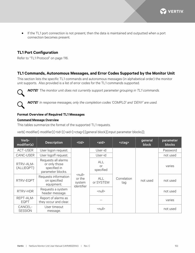
Vertiv | NetSure Monitor Unit User Manual (UM1M832DNA) | Rev. C 153
• If the TL1 port connection is not present, then the data is maintained and outputted when a port connection becomes present.
TL1 Port Configuration Refer to “TL1 Protocol” on page 116.
TL1 Commands, Autonomous Messages, and Error Codes Supported by the Monitor Unit This section lists the specific TL1 commands and autonomous messages (in alphabetical order) the monitor unit supports. Also provided is a list of error codes for the TL1 commands supported.
NOTE! The monitor unit does not currently support parameter grouping in TL1 commands.
NOTE! In response messages, only the completion codes ‘COMPLD’ and ‘DENY’ are used.
Format Overview of Required TL1 Messages Command Message Overview
This tables summarize the format of the supported TL1 requests.
verb[-modifier[-modifier]:[<tid>]:[<aid>]:<ctag>[:[general block][:input parameter blocks]];
Verb-modifier(s)
Description <tid> <aid> <ctag> general block
parameter blocks
ACT-USER User logon request.
<null> or the
system identifier
User-id
Correlation tag not used
Password
CANC-USER User logoff request. User-id not used
RTRV-ALM-{ALL|EQPT}
Requests all alarms or only those specified in
parameter blocks.
ALL or
specified varies
RTRV-EQPT Requests information
on specified equipment.
ALL or SYSTEM not used
RTRV-HDR Requests a system header message. <null> not used
REPT-ALM-EQPT
Report of alarms as they occur and clear. -- varies
CANCEL-SESSION
User timeout message. <null> not used
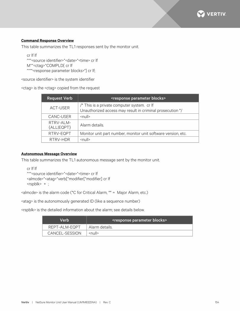
Vertiv | NetSure Monitor Unit User Manual (UM1M832DNA) | Rev. C 154
Command Response Overview
This table summarizes the TL1 responses sent by the monitor unit.
cr lf lf ^^^<source identifier>^<date>^<time> cr lf M^^<ctag>^COMPLD[ cr lf ^^^"<response parameter blocks>"] cr lf;
<source identifier> is the system identifier
<ctag> is the <ctag> copied from the request
Request Verb <response parameter blocks>
ACT-USER /* This is a private computer system. cr lf Unauthorized access may result in criminal prosecution */
CANC-USER <null>
RTRV-ALM-{ALL|EQPT} Alarm details.
RTRV-EQPT Monitor unit part number, monitor unit software version, etc. RTRV-HDR <null>
Autonomous Message Overview
This table summarizes the TL1 autonomous message sent by the monitor unit.
cr lf lf ^^^<source identifier>^<date>^<time> cr lf <almcde>^<atag>^verb[^modifier[^modifier] cr lf <rspblk> + ;
<almcde> is the alarm code (*C for Critical Alarm, ** = Major Alarm, etc.)
<atag> is the autonomously generated ID (like a sequence number)
<rspblk> is the detailed information about the alarm; see details below.
Verb <response parameter blocks>
REPT-ALM-EQPT Alarm details. CANCEL-SESSION <null>
Vertiv | NetSure Monitor Unit User Manual (UM1M832DNA) | Rev. C 155
Samples TL1 Message Samples
These samples use the system identifier (<tid>): Lorain.
Autonomous Message on Connect
When the Telnet connection is established, the monitor unit will provide the active alarms in an autonomous message. In this example, there are two alarms.
Lorain 15-09-24 13:47:00 *C 1 REPT ALM EQPT "PowerSystem:CR,Alarm,SA,09-24,13-45-31,,,1,,1-MIN:\"CAN Communication Failure\"," "PowerSystem:CR,Alarm,SA,09-23,13-39-43,,,1,,1-DAY:\"SPD\"," ; <
Activate User
The ACT-USER request (example: ACT-USER::drw:51::1_2345; for username drw with password 1_2345) can be used to log in. The monitor unit will not respond to requests unless a user is logged in (or the monitor unit is configured with auto-login). The monitor unit responds with this message:
Lorain 15-09-24 15:29:14 M 51 COMPLD /* This is a private computer system. Unauthorized access may result in criminal prosecution */ ; <
Cancel User
The CANC-USER request (example: CANC-USER:Lorain:drw:16; for username drw) can be used to log-out the current user. The monitor unit responds with this message:
Lorain 15-09-25 08:18:04 M 16 COMPLD ; <
Retrieve Header
The RTRV-HDR request (example: RTRV-HDR:::20;) can be used to ‘ping’ the monitor unit to confirm that there is a connection established. The monitor unit responds with this message:
Lorain 15-09-25 08:17:57 M 20 COMPLD ; <
Retrieve Equipment
The RTRV-EQPT request (example: RTRV-EQPT:Lorain:SYSTEM:40;) can be used to get information about the monitor unit. The monitor unit responds with this message:
Lorain 15-09-25 08:17:55 M 40 COMPLD "SYSTEM:M830B::SWVER=1.00,CURSWVER=1.1.41T04,:IS-NR," ; <
The monitor unit type is M830B. The configuration is version 1.00. The software version is 1.1.41T04.
Vertiv | NetSure Monitor Unit User Manual (UM1M832DNA) | Rev. C 156
Retrieve Alarms
The RTRV-ALM-ALL request (example: RTRV-ALM-ALL::ALL:53::;) can be used to retrieve all alarms. The monitor unit responds with this message:
Lorain 15-09-24 15:29:35 M 53 COMPLD "PowerSystem,EQPT:CR,ConditionType,SA,09-24,15-22-54,,,6-MIN:\"ConditionDescription\"," "PowerSystem,EQPT:CR,Alarm,SA,09-23,13-39-43,,,1-DAY:\"SPD\"," "PowerSystem,EQPT:CR,Alarm,SA,09-24,15-24-53,,,4-MIN:\"Under Voltage 2\"," "RectifierGroup,EQPT:CR,Alarm,SA,09-24,15-25-12,,,4-MIN:\"Rectifier Lost\"," ; <
In this case there are 4 critical, service-affecting alarms. The description of the first alarm was changed to show how the Condition Type and Condition Description are used. See Section 4.1.
The RTRV-ALM-ALL request can be used to filter the alarms and retrieve a subset of the alarms (example: RTRV-ALM-EQPT::ALL:57::CR; to get the CR critical alarms). The monitor unit responds with this message:
Lorain 15-09-25 08:17:59 M 57 COMPLD "PowerSystem,EQPT:CR,ConditionType,SA,09-25,07-52-54,,,25-MIN:\"ConditionDescription\"," "PowerSystem,EQPT:CR,Alarm,SA,09-23,13-39-43,,,1-DAY:\"SPD\"," "PowerSystem,EQPT:CR,Alarm,SA,09-25,07-54-58,,,23-MIN:\"Under Voltage 2\"," "RectifierGroup,EQPT:CR,Alarm,SA,09-25,07-55-12,,,22-MIN:\"Rectifier Lost\"," ; <
Error Response
The monitor unit will respond with an error message if there are any issues with the request. (Note that the monitor unit will not respond if the system identifier does not match or if the user is not logged in.)
Here is an example of the monitor unit response when an invalid command (RTRV-ALM-EQPTX::ALL:57::CR;) is sent:
Lorain 15-09-25 08:18:15 M 57 DENY ICNV /* Command not valid */ ; <
Vertiv | NetSure Monitor Unit User Manual (UM1M832DNA) | Rev. C 157
TL1 Autonomous Message Sample
The DI1 alarm occurs.
When the alarm occurs, the monitor unit sends this autonomous message:
LorainLab 15-09-24 13:49:42 *C 8 REPT ALM EQPT "PowerSystem:CR,Alarm,SA,09-24,13-49-41,,,0,0,0-MIN:\"DI1 Alarm\"," ; <
When the alarm clears, the monitor unit sends this autonomous message:
LorainLab 15-09-24 13:50:06 A 9 REPT ALM EQPT "PowerSystem:CL,Alarm,SA,09-24,13-50-06,,,0,1,0-MIN:\"DI1 Alarm\"," ; <
Table of TL1 Commands Supported Refer to Table 10 for a list of all TL1 commands supported, with a short description of each command.
Table 10: TL1 Commands Supported
TL1 Commands Supported Description
ACTIVATE-USER ACT-USER
Sets up a session with the system (i.e., logging into the system).
CANCEL-USER CANC-USER
Terminates a session with the system (i.e., logging off of the system).
RETRIEVE-ALARM RTRV-ALM-{EQPT|ALL}
Instructs the system to send the current state of its alarm conditions associated with one or more equipment units, facilities, etc. within the system.
RETRIEVE-EQUIPMENT RTRV-EQPT
Instructs the system to send the current monitor unit software version and the monitor unit software configuration part number and revision.
RETRIEVE-HEADER RTRV-HDR
Requests that the system reply with a "normal" response indicating COMPLD.
Vertiv | NetSure Monitor Unit User Manual (UM1M832DNA) | Rev. C 158
Expanded Description of TL1 Commands Supported (in alphabetical order) This section lists the specific TL1 commands (in alphabetical order) the monitor unit supports and provides a broader description of the command.
ACTIVATE-USER (ACT-USER)
Referenced In: TR-NWT-000835, Issue 3; pg. 3-23
General Description: This command is for setting up a session with the NE (monitor unit) [i.e., logging into the NE (monitor unit)]. An entry is made in the monitor unit’s event log indicating this command was executed by the User who initiated the command. The event description indicates that a User session was established and also identifies the User who executed the command.
When a valid User session has been previously established and this command is entered with a valid User name (<uid>) and password (<pid>), the User specified in the command becomes the User that is logged on. An entry is made in the monitor unit’s event log as stated above.
The User name and password parameters entered with this command are checked against the monitor unit’s list of Users.
It is the responsibility of the person adding a User to the monitor unit’s User list to insert values for the User name and password fields that are compatible with the operation of the TL1 interface. It is the responsibility of the monitor unit software to ensure that User name and password values entered with this command meet the requirements of the TL1 interface.
Monitor Unit Access Level: any access level
Input Format:
ACT-USER:[<tid>]:<aid>:<ctag>::<pid>;
<aid>
For this command, the access identifier is the User name (<uid>). Invalid values received for this parameter return an error response with the error code IIAC.
<pid>
This is the private identifier (i.e., password) of the User who is attempting to gain access.
Normal Response Format:
cr lf lf ^^^<source identifier>^<date>^<time> cr lf M^^<ctag>^COMPLD cr lf ^^^/* This is a private computer system. cr lf Unauthorized access may result in criminal prosecution */ cr lf;
Vertiv | NetSure Monitor Unit User Manual (UM1M832DNA) | Rev. C 159
CANCEL-USER (CANC-USER)
Referenced In: TR-NWT-000835, Issue 3; pg. 3-33
General Description: This command is for terminating a User session [i.e., logging off of the NE (monitor unit)].
Monitor Unit Access Level: any access level
Input Format:
CANC-USER:[<tid>]:<aid>:<ctag>;
<aid>
For this command, the access identifier is the User identifier(<uid>). Invalid values received for this parameter return an error response with the error code IIAC.
Normal Response Format:
No response is returned if a valid User session has not been established. Otherwise the response is in the following format.
cr lf lf ^^^<source identifier>^<date>^<time> cr lf M^^<ctag>^COMPLD cr lf
Vertiv | NetSure Monitor Unit User Manual (UM1M832DNA) | Rev. C 160
RETRIEVE-ALARM (RTRV-ALM-{EQPT|ALL})
Referenced In: TR-NWT-000833, Issue 5; pg. 4-205
General Description: Instructs the NE (monitor unit) to send the current state of its alarm conditions associated with one or more equipment units, facilities, etc. within the NE (monitor unit).
Monitor Unit Access Level: any access level
Input Format:
RTRV-ALM-{EQPT|ALL}:
[<tid>]:<aid>:<ctag>::[<ntfcncde>],[<condtype>], [<srveff>],[<locn>],[<dirn>][,<tmper>];
NOTE! The command code modifier of COM is not supported. If specified, an error response with the error code ICNV is returned.
<aid>
A value of ALL requests retrieval of alarm conditions for all AIDs of the type defined by the command code modifier. Use of the command code modifier ALL results in retrieval of all alarm conditions in the NE (monitor unit).
If the command code modifier is ALL, the <aid> must be ALL. A <null> value is not permitted for this parameter.
<ntfcncde>
This is the notification code associated with the alarm conditions being retrieved. Valid values for this parameter are as follows:
CR critical alarm
MJ major alarm
MN minor alarm
<null> request retrieval of alarm conditions for all of the above codes
<condtype>
This is the condition type of alarm conditions to be retrieved. A <null> value causes all conditions classified as alarm conditions to be retrieved.
<srveff>
This is the effect on service caused by the alarm condition. Valid values for this parameter are as follows:
SA service-affecting condition
NSA nonservice-affecting condition
<null> request retrieval of alarm conditions for both of the above codes
Vertiv | NetSure Monitor Unit User Manual (UM1M832DNA) | Rev. C 161
<locn>
This is the location of the alarm condition. This parameter does not apply to this application. A <null> value is the only value which is accepted for this parameter. If any other value is received for this parameter, an error response is returned with the error code INUP.
<dirn>
This is the direction of the alarm condition. This parameter does not apply to this application. A <null> value is the only value which is accepted for this parameter. If any other value is received for this parameter, an error response is returned with the error code INUP.
<tmper>
This is the accumulation time period for PM parameters. This parameter does not apply to this application. A <null> value is the only value which is accepted for this parameter. Other values for this parameter generate an error response using the error code “INUP”.
Normal Response Format:
No response is returned if a valid User session has not been established. Otherwise the response is in the following format.
cr lf lf ^^^<source identifier>^<date>^<time> cr lf M^^<ctag>^COMPLD [ <rspblk>] cr lf ;
<rspblk>
This is the response block which may be repeated multiple times.
cr lf
^^^”[<aid>][,<aidtype>]:<ntfcncde>,<condtype>,<srveff>, [<ocrdat>],[<ocrtm>],[<locn>],[<dirn>][,<tmper>] [:[<conddescr>],[<aiddet>][,<obsdbhvr>[,<exptdbhvr>]] [:[<dgntype>][,<tblistl>]]]”
<aidtype>
This is the type of access identifier. Valid values for this application are:
EQPT equipment
If the command code modifier is ALL, <aidtype> is required to specify the type of access identifier, else <aidtype> may be <null>.
<ntfcncde>
This is the notification code associated with a single alarm condition given in this block.
<condtype>
This is the condition type of the alarm condition being given in this block.
Vertiv | NetSure Monitor Unit User Manual (UM1M832DNA) | Rev. C 162
<srveff>
This is the effect on service caused by the single alarm condition given in this block.
<ocrdat>
This is the date when the triggering event occurred. The format for this parameter is MOY-DOM(Month-Of-Year - Day-Of-Month). MOY ranges from 1 to 12 and DOM ranges from 1 to 31.
A <null> value for this parameter defaults to the current date unless <ocrtm> is <null>, then this parameter does not apply.
<ocrtm>
This is the time when the triggering event occurred. The format for this parameter is HOD-MOH-SOM (Hour-Of-Day - Minute-Of-Hour - Second-Of-Minute). HOD ranges from 0 to 23. MOH and SOM range from 0 to 59.
A <null> value means this parameter and <ocrdat> are not applicable.
Unimplemented Parameters
The following two parameters do not apply to this application. A <null> value is inserted for them.
<locn> - location of alarm condition
<dirn> - direction of alarm condition
<tmper>
This is the accumulation time period for PM parameters. In this application, it represents the length of time the alarm condition has been active. The format for this parameter is “VAL-UN”, where valid values for VAL (value) and UN (units) are given below.
VAL UNIT
1 DAY (days) - used if alarm is active longer than 24 hours.
1 to 24 HR (hours)
1 to 1440 MIN (minutes) - used if alarm is active less than 24 hours.
<conddescr>
This parameter is a text message which provides a detailed description of the alarm, event, or condition. It is an ASCII string enclosed within a pair of escaped quotes(\”). It may also be used to describe any action to be taken as a result of the condition.
Unimplemented Parameters
NOTE! The following parameters will either not be implemented or do not apply to this application. A <null> value is returned for these parameters.
<aiddet> - supplementary equipment identification
<obsdbhvr> - observed behavior that resulted in reported trouble

Vertiv | NetSure Monitor Unit User Manual (UM1M832DNA) | Rev. C 163
<exptdbhvr> - expected behavior that was deviated from
<dgntype> - diagnostic routine used to isolate trouble
<tblistl> - provides isolation information
Vertiv | NetSure Monitor Unit User Manual (UM1M832DNA) | Rev. C 164
RETRIEVE EQUIPMENT (RTRV-EQPT)
General Description: This command message retrieves the software version of the specified equipment. For this application it retrieves the monitor unit software version and the monitor unit software configuration part number and revision.
Monitor Unit Access Level: any access level
Input Format:
RTRV-EQPT:[<tid>]:<aid>:<ctag>;
<aid>
The AID parameter specifies the equipment whose information is to be retrieved. Valid values for the AID in this application are “SYSTEM” and “ALL”. Both values will retrieve only the software version information for the power system monitor unit.
Normal Response Format:
cr lf lf ^^^<source identifier>^<date>^<time> cr lf M^^<ctag>^COMPLD cr lf ^^^”<aid>:[<eqpt_type>]:[<cur_eqpt>]:[SWVER=<swver>], [CURSWVER=<curswver>],[DSPSWVER=<dspswver>]:<state>,[<sst>]” crlf ;
<aid>
This is the type of access identifier of the equipment whose information is being provided. This value is always “SYSTEM” indicating that it is the system processor (i.e., monitor unit).
<eqpt_type>
This is the type of equipment installed. Valid values for this application is the monitor unit part number.
<cur_eqpt>
This is the type of equipment actually installed. Valid values for this application is <null>.
<swver>
Version of software that is configured. This is an ASCII string from one to thirty-two characters. The value of this parameter is the monitor unit’s software configuration part number and revision (e.g., “552365AB”). If no configuration part number is available, the value is <null>.
<curswver>
Version of software that is actually installed. This is an ASCII string from one to thirty-two characters. The value of this parameter is the monitor unit’s software version (e.g., “1.30”). If no software version is available, the value is <null>.
Vertiv | NetSure Monitor Unit User Manual (UM1M832DNA) | Rev. C 165
<dspswver>
Version of DSP code on the device. This parameter does not apply to this application. A value of <null> is always outputted for this parameter.
<state>
This is the operational state of the equipment. Valid values are: IS-NR (In Service – Normal), OOS-AUMA (Out Of Service – Autonomous and Management). A value of IS-NR” should always be returned because a response to the command indicates that the monitor unit is operational.
<sst>
This is the secondary state of the equipment. This parameter is not available in this application. A value of <null> is always outputted for this parameter.
Vertiv | NetSure Monitor Unit User Manual (UM1M832DNA) | Rev. C 166
RETRIEVE-HEADER (RTRV-HDR)
Referenced In: TR-NWT-000833, Issue 5; pg. 4-283
General Description: Requests that the NE (monitor unit) reply with a "normal" response indicating COMPLD. The information of interest in the reply is the reply itself along with information that the NE (monitor unit) has about itself, namely the <source identifier>, the <date>, and the <time>.
This command can be used to verify the access to a specific NE (monitor unit).
Monitor Unit Access Level: any access level
Input Format:
RTRV-HDR:[<tid>]:<aid>:<ctag>;
<aid>
The <aid> in this command must be <null> since it does not apply.
Normal Response Format:
cr lf lf ^^^<source identifier>^<date>^<time> cr lf M^^<ctag>^COMPLD cr lf
Vertiv | NetSure Monitor Unit User Manual (UM1M832DNA) | Rev. C 167
TL1 Autonomous Messages Supported (in alphabetical order) This section lists the specific autonomous messages (in alphabetical order) the monitor unit supports. A brief description of each is provided.
NOTE! In autonomous messages, the fractional portion of the ATAG is not supported.
CANCEL SESSION (TIMEOUT)
Referenced In: TR-TSY-000835, Issue 2; pg. 12.5-13
General Description: This is an automatic message transmitted by the NE (monitor unit) when an established session is terminated because of a "timeout", i.e., no messages were exchanged for an interval equal the monitor unit session timeout setting.
Message Format:
cr lf lf ^^^<sid>^<YY-MM-DD>^<HH:MM:SS> cr lf A^^<atag>^CANC cr lf <uid> cr lf ;
<uid>
This is the User whose session is terminated as a result of the timeout.
Vertiv | NetSure Monitor Unit User Manual (UM1M832DNA) | Rev. C 168
REPORT ALARM (REPT ALM {EQPT/COM})
Referenced In: TR-NWT-000833, Issue 5; pg. 5-5
General Description: Generated by an NE (monitor unit) to report the occurrence of alarmed events. Trouble events occurring in the NE (monitor unit) are classified as alarmed or non-alarmed events.
Message Format:
cr lf lf ^^^<source identifier>^<date>^<time> cr lf <almcde>^<atag>^REPT^ALM^EQPT cr lf <rspblk> cr lf;
NOTE! The only second message modifier supported for this monitor unit application is ‘EQPT’. Other message modifiers allowed by the TL1 protocol standards are not supported.
<rspblk>
This is the response block which may be repeated multiple times.
^^^”<aid>:<ntfcncde>,<condtype>,<srveff>, [<ocrdat>],[<ocrtm>],[<locn>],[<dirn>], [<monval>],[<thlev>][,<tmper>] [:[<conddescr>],[<aiddet>][,<obsdbhvr>[,<exptdbhvr>]] [:[<dgntype>][,<tblistl>]]]”
In this application each individual response block specifies only one alarm. Use of multiple values for parameters (referred to as parameter grouping) in the response block is not supported.
<aid>
Identifies the single entity in the NE (monitor unit) to which the alarm pertains.
<ntfcncde>
This is the notification code associated with a single alarm condition given in this block. Valid values are as follows:
CR Critical alarm
MJ Major alarm
MN Minor alarm
CL Cleared alarm
For this application, values are derived from the notification code configuration parameter of the monitor unit configuration with which the alarm condition is associated. The exception to this is the CL code which is used when reporting an alarm has cleared.
<condtype>
This is the condition type of the alarm. It indicates the type of failure that has occurred/cleared.
Vertiv | NetSure Monitor Unit User Manual (UM1M832DNA) | Rev. C 169
<srveff>
This is the effect on service caused by the single alarm condition given in this block. Valid values are as follows:
SA Service-affecting condition immediate action required.
NSA Nonservice-affecting condition, action required.
<ocrdat>
This is the date when the triggering event occurred (i.e., the threshold was crossed). The format for <ocrdat> is MOY-DOM. MOY ranges from 1 to 12 and DOM ranges from 1 to 31. A <null> value for this parameter defaults to the date in the message header.
<ocrtm>
This is the time when the event occurred. The format for <ocrtm> is HOD-MOH-SOM. HOD ranges from 0 to 23. MOH and SOM range from 0 to 59. A <null> value for this parameter defaults to the time in the message header.
NOTE! The following two parameters do not apply to this application. A <null> value is inserted for them.
<locn> - location of alarm condition
<dirn> - direction of alarm condition
<monval>
This is the measured value of the monitored value associated with the alarm condition. A <null> value is inserted if there is no measured value associated with this trouble.
<thlev>
This is the value of the threshold level if the <condtype> is a threshold violation. A <null> value means there is no threshold level associated with the alarm condition.
<tmper>
This is the accumulation time period for PM parameters. In this application it represents the length of time the alarm condition has been active. The format for this parameter is “VAL-UN”, where valid values for VAL (value) and UN (units) are given below.
VAL UNIT
1 DAY (days) - used if alarm is active longer than 24 hours.
1 to 24 HR (hours)
1 to 1440 MIN (minutes) - used if alarm is active less than 24 hours.
<conddescr>
This parameter is a text message which provides a detailed description of the alarm, event, or condition. It is an ASCII string enclosed within a pair of escaped quotes (\”). It may also be used to
Vertiv | NetSure Monitor Unit User Manual (UM1M832DNA) | Rev. C 170
describe any action to be taken as a result of the condition. For this application, values are derived from the condition description configuration parameter of the monitor unit configuration with which the alarm condition is associated. If the parameter has not been configured, a <null> is inserted for this parameter.
Unimplemented Parameters
NOTE! The following parameters are either not implemented or do not apply to this application. A <null> value is inserted for them.
<aiddet> - supplementary equipment identification
<obsdbhvr> - observed behavior that resulted in reported trouble
<exptdbhvr> - expected behavior that was deviated from
<dgntype> - diagnostic routine used to isolate trouble
<tblistl> - provides isolation information
Vertiv | NetSure Monitor Unit User Manual (UM1M832DNA) | Rev. C 171
List of Error Codes for TL1 Commands Supported (in alphabetical order) This section provides a list of error codes for the TL1 commands supported.
ENEQ - Equipage, Not EQuipped ENRI - Equipage, Not equipped for Retrieving specified Information ENSI - Equipage, Not equipped for Setting specified Information ICNV - Input, Command Not Valid IDNV - Input, Data Not Valid IIAC - Input, Invalid Access Identifier IICT - Input, Invalid Correlation Tag IIFM - Input, Invalid Data Format IIPG - Input, Invalid Parameter Grouping IISP - Input, Invalid Syntax or Punctuation IITA - Input, Invalid TArget identifier INUP - Input, Non-null Unimplemented Parameter IORD - Input, Out of Range Data PICC - Privilege, Illegal Command Code PIFC - Privilege, Illegal Field Code PIUC - Privilege, Illegal User Code PIUI - Privilege, Illegal User Identity SARB - Status, All Resources Busy SCNF - Status, Command Not Found SDNR - Status, Data Not Ready SROF - Status, Requested Operation Failed
Vertiv | NetSure Monitor Unit User Manual (UM1M832DNA) | Rev. C 172
REPLACEMENT PROCEDURES Monitor Unit Replacement DANGER! Follow all “Important Safety Instructions” found in the documentation provided with the
system the monitor unit is installed in.
ALERT! MONITOR UNIT HANDLING. Installation or removal of the monitor unit requires careful handling. To avoid possibility of monitor unit damage from static discharge, a static wrist strap grounded through a one megohm resistor should always be worn when handling the monitor unit. ESD-protective packaging material must also be used when carrying/shipping the monitor unit.
NOTE! Depending on your network security settings, when you remove a device that is connected to your network and assign the same IP address to the replacement device, you may not be allowed to communicate with the replacement device over the network. Contact your network administrator for assistance.
The monitor unit is hot swappable. It can be removed and installed with the system operating and without affecting the output bus.
Procedure
1. Before performing this procedure, ensure the replacement monitor unit contains the same configuration file as the existing monitor unit. Refer to the Configuration File Part Number Label on the side of the replacement monitor unit for the Configuration Part Number (see Figure 81). If the existing monitor unit is operational, navigate the menus to view its configuration file (MAIN SCREEN / ESC).
2. Performing this procedure may activate external alarms. Do one of the following. If possible, disable these alarms. If these alarms cannot be easily disabled, notify the appropriate personnel to disregard any future alarms associated with this system while this procedure is being performed.
3. Connect an approved grounding strap to your wrist. Attach the other end to a suitable ground.
4. Remove any cover or device securing the monitor unit in the system.
5. Slide the monitor unit completely from the system.
6. Slide the replacement monitor unit completely into its mounting position.
7. Replace any cover or device securing the monitor unit in the system.
8. Wait for the monitor unit to finish booting and verify that the complete system operates normally.
9. Enable the external alarms, or notify appropriate personnel that this procedure is finished.
10. Ensure that there are no local or remote alarms active on the system.
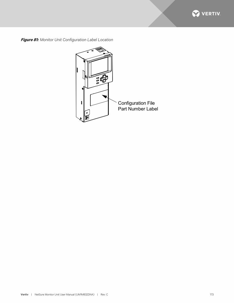
Vertiv | NetSure Monitor Unit User Manual (UM1M832DNA) | Rev. C 173
Figure 81: Monitor Unit Configuration Label Location
Configuration FilePart Number Label
Vertiv | NetSure Monitor Unit User Manual (UM1M832DNA) | Rev. C 174
SPECIFICATIONS Input Voltage Range: 19 VDC to 60 VDC.
Power Consumption, Maximum: 18 W.
Operating Temperature Range: -40 °C to +70 °C (-40 °F to +158 °F).
Relative Humidity: Capable of operating in an ambient relative humidity range of 0% to 90%, non-condensing.
Environment: The monitor unit is recommended to be used in Pollution of Degree 2. Pollution Degree 2 applies where there is only non-conductive pollution that might temporarily become conductive due to occasional condensation (such as the office -environment).
Weight: < 1 kg (2.2 lbs).
Front Panel Display:
• 320 x 240 Pixels TFT LCD
Indicators:
• Status (Green)
• Observation Alarm (Yellow)
• Critical / Major Alarm (Red)
Local and Remote Access Passwords: Refer to “Passwords and Privilege Levels” on page 12.
Inputs and Outputs: Connection points provided on monitor unit interface board(s) mounted in the system. Refer to your system documentation.
Factory Default Setpoints: Refer to the configuration drawing (C-drawing) furnished with your system for a list of factory default values.
Safety and Standards Compliance:
• Electrical: IEC 60950-1, EN 60950-1, UL 60950-1
• EMC: EN 300 386, 2001 Class B; FCC Part 15, Class B
• Environmental: CE; NEBS Level 3
• GR-3108 Class 2 Compliant

Vertiv | NetSure Monitor Unit User Manual (UM1M832DNA) | Rev. C 175
This page is intentionally blank.

Vertiv.com | Vertiv Headquarters, 1050 Dearborn Drive, Columbus, OH, 43085, USA UM1M832DNA (RC 11/19)