Embed Size (px)
Citation preview

ALIGNMENT STRATEGY OF SESAMET. Abu‐Hanieh, SESAME, Jordan
IWAA2014, IHEP, Beijing, China 13‐17 October 2014

Foster excellent science and technology in the Middle East and prevent or reverse the brain drain
Build bridges between diverse societies
SESAME‐Members:Bahrain, Cyprus, Egypt, Israel, Iran, Jordan, Pakistan, Palestine, Turkey.
Observers: Brazil, China, France, Germany, Greece, Italy, Japan, Kuwait, Portugal, Russia, Sweden, Switzerland, UK and USA.
IWAA2014, IHEP, Beijing, China 13‐17 October 2014
SESAME Mission

Layout of SESAME Showing Phase1 Beamlines
EUV BL
SAXS‐WAXS
IR
XRF‐XAFS
VUV
PX
PD
IWAA2014, IHEP, Beijing, China 13‐17 October 2014
Energy; 2.5 GeV
Circumference; 133m
12 Insertion Devices
13 Bending Magnet beamlines
Maximum beamline length; 37m
Space for future full energy injector in main ring tunnel
IWAA2014, IHEP, Beijing, China 13‐17 October 2014
Status of SESAME Machine
Successfully having brought SESAME’s Booster to full operation is of particularsignificance since this is the first high-energy accelerator in the Middle East.
This success will open the path for the final goal, which is to make SESAME thefirst operational Synchrotron Light Source in the Middle East.
After the completion of the shielding walls; SESAME’s Microtron becameoperational in 2012.
Installation of its Booster was completed in 2013. And on 3rd September, 2014 the SESAME team succeeded in accelerating the
electrons in the Booster to their final energy of 800 MeV.

www.sesame.org.jo
IWAA2014, IHEP, Beijing, China 13‐17 October 2014

Booster Main Components & Diagnostics
Screen 1(Original)
Screen 2(Original)
Injection septum
Full‐turn screen (Original)
BPM 2
BPM 3
BPM 4
BPM 6
BPM 5with CT
BPM 1
Extraction kicker
RF cavity
Injection kicker
Extraction septum
FCT + DCCT
VL Diagnosticbeam line
Hor. Corrector
TL1 FCTTL1 screen
IWAA2014, IHEP, Beijing, China 13‐17 October 2014

IWAA2014, IHEP, Beijing, China 13‐17 October 2014
Alignment Team, Collaboration, Instrumentation
The Survey and Alignment work is one of the Mechanical EngineeringGroup tasks, the group consists of three Mechanical Engineers; One is 50%dedicated for the Survey and Alignment.
Developing Alignment Strategy, designing the Alignment Network andOptimising the Network needs dedicated efforts and knowledge. To performthese in a right and accurate way; the group has strong collaboration withSoleil Synchrotron (Alignment Group).
Industrial Total Station (TDA5005).
Automatic Level (NA2)

IWAA2014, IHEP, Beijing, China 13‐17 October 2014
Alignment Network
The Alignment Network at SESAME is made of set of wallbrackets and floornails (brass) spread all around the accelerators and beamlines.
Wall brackets are cast aluminum Wall Brackets, very stiff, light, and extremelystable; used as references with accurate positions; they are used to hold theTDA5005 and its Reflector; they act as absolute and accurate mechanicalreferences.

IWAA2014, IHEP, Beijing, China 13‐17 October 2014
Primary Alignment Network Measurement
The primary geodesic network is made of 16 wall brackets installed on the concretecolumns surrounding the experimental hall.

IWAA2014, IHEP, Beijing, China 13‐17 October 2014
Primary Alignment Network Measurement
The calculations of the final wallbracket planimetric co‐ordinates wereobtained by a least square bundleadjustment performed by SOLEIL’ssoftware called reseau.m anddeveloped with MatLab.
The error for the angle measurementswas 0.00045 deg, and for the distancemeasurements was 0.15 mm.
Two wall brackets out of the 16 havebeen fixed later for the line of sighton the exact diameter of the SR.

IWAA2014, IHEP, Beijing, China 13‐17 October 2014
Line of Sight through Shielding Walls

IWAA2014, IHEP, Beijing, China 13‐17 October 2014
Floor Nails on Beam Path
Brass Nails have been sealed at the floorsurface level, on which we carved smallhole on its surface that is accuratelymeasured on the beam projected axes.
163 points have been traced as follows:two points defining TL1, 18 points forthe Booster, 10 points defining TL2, 33points defining SR, 100 points definingBeamlines.

IWAA2014, IHEP, Beijing, China 13‐17 October 2014
Leveling Benchmarks
Steel nails are installed as leveling Benchmarks,3 in the Booster area and 8 in the Storage Ring.
All leveling measurements were done using NA2Automatic Level.
The measurements were done in three steps: Stationat the Booster centre, Station at the Storage Ringcentre, and 8 Stations between each LevelingBenchmark as a closed traverse.
The Z of the SR & BL beams are defined by Z = 0. The Z of the BOO beam is then defined by Z = -200
mm.

IWAA2014, IHEP, Beijing, China 13‐17 October 2014
Booster Alignment
Four wall brackets have beeninstalled in the BOO tunnel;where after the wall bracketsinstallation a survey of the setWB‐brass nails were done to do thecalculation of the WB coordinateswith respect to brass nails.
Girder Dipole Quadrupole
S (mm) ±2 ±0.5 ±0.5
X (mm) ±2 ±0.2 ±0.2
Z (mm) ±2 ±0.2 ±0.2
S (mrad) ±0.2 ±0.2
X (mrad) ±0.2 ±0.2
Z (mrad) ±1 ±1
Booster Tolerances

IWAA2014, IHEP, Beijing, China 13‐17 October 2014
Booster Girders Installation

IWAA2014, IHEP, Beijing, China 13‐17 October 2014
Booster Magnets Installation

IWAA2014, IHEP, Beijing, China 13‐17 October 2014
Booster Magnets Fiducials
Two survey monuments are onthe top surface of the dipoles. No information from BESSY1about their exact location withrespect to the magnetic centre. The monuments location withrespect to the magnetic definitionof the dipole has been measuredby mechanical measurementswhere finding the magnetic axesof the dipole is not necessary.
A gauge have been designed and used for the alignmentof the Qpoles. The gauge is equipped with threecontact points and a pair of small fiducials (ø24mm)and used in two reversed positions to define the Qpoleaxes. The gauge also is in contact with the laminas bymeans of three shoulders, one on a side and two on theother side.

IWAA2014, IHEP, Beijing, China 13‐17 October 2014
Booster Magnets Pre‐Alignment
A pre‐alignment in collaboration with Soleil’s alignment group has been performed on all theQpoles and dipoles in order to make an accurate survey, this operation allows to set the magnetsclose to their theoretical position (within ±1mm in S, X, Z and less than ± 0.5mrad)
The result of the survey shows that a fine tuning is requested for several magnets

IWAA2014, IHEP, Beijing, China 13‐17 October 2014
Booster Magnets Final Alignment
A second Survey has been done to check the position of all the magnets after the corrections thathave been done, there were still some magnets out of range. This process has been repeated untilall the magnets are in a correct position
Measurement uncertainty: ±0.05mm, 1 sigma for X and Z axis, ±0.15mm, 1 sigma for S axis and±0.05mrad 1 sigma for Tilt
IWAA2014, IHEP, Beijing, China 13‐17 October 2014
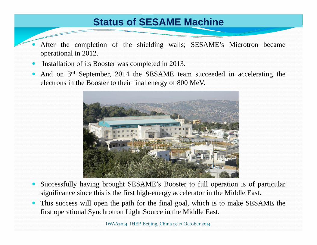
Pulsed Magnets
The pulsed magnets have been opened inside the vacuum lab, for measuring and aligning theactive parts inside, and taking the offsets to be installed inside Booster Tunnel.Because of a lack of documentation, the accelerator physicist had to calculate the position of thebeam inside these pulsed magnets

IWAA2014, IHEP, Beijing, China 13‐17 October 2014
Transfer Line 1 (TL1)
TL1 is composed from two sets of two magnets embedded in metal flanges. The TDA5005 hasbeen placed exactly on the theoretical position of the beam and using Plexiglas targets, themagnets and girders have been set in place. As the vacuum chamber is cantered on the poles ofthe magnets and as it wasn’t possible to measure the poles directly, the vacuum chamber hasbeen used as the reference for centring these magnets.

IWAA2014, IHEP, Beijing, China 13‐17 October 2014
Microtron
The Microtron has been set up to its theoretical position, using the free station technique byplacing the TDA exactly on the theoretical axis of TL1.Rs rotation is done by measuring two points of the Microtron flanges, the horizontality isrealised when the two points have the same x coordinate (it means the two points are perfectlyvertical with respect to each other within the Microtron flange’s tolerance)

IWAA2014, IHEP, Beijing, China 13‐17 October 2014
Next Steps …
Quadrupoles monumentsDesigning, installing, and measuring new permanent fiducials booster quadrupoles tobe used for the survey in the future instead of the long and hard process of using theheavy quadrupole gauge.
Storage Ring Alignment NetworkInstalling the wallbrackets inside the SR tunnel, surveying the set WB‐brass nails to dothe calculation of the WB co‐ordinates. Then, tracing the locations of SR girders andinstalling them, followed by the installation of storage ring magnets.
TL2 Installation and AlignmentInstalling all the girders, magnets, and components of transfer line2 on their rightpositions, and doing the fine alignment required to deliver the beam from the boosterring to the storage ring.
Laser TrackerSESAME is in the process of purchasing a new Laser Tracker; this will enhance thecapabilities of the alignment work at SESAME. Training on the Laser Tracker isrequired and will be planned to.
Spatial Analyzer SoftwareGetting Trained on SA software, and making a full survey of booster magnets tocompare the SA results with the MatLab results calculated by Soleil’s software.

IWAA2014, IHEP, Beijing, China 13‐17 October 2014
SESAME, someday
SESAME is now at a keytransitional stage moving fromconstruction activities throughinto machine installation andcommissioning.
The booster network is installedand qualified, and the storagering network in the process.
Future work activities include theinstallation and pre‐alignment ofstorage ring components and theinstallation of phase 1 beamlines.
The development of survey andmetrology techniques during thisnext phase of the project providesexciting challenges for SESAMESurvey Team

IWAA2014, IHEP, Beijing, China 13‐17 October 2014