Embed Size (px)
Citation preview

ALFOplus Series – High Capacity IP Full Outdoor
Brochure
Document Number
B. ALFOplus.1.03-11
SIAE MICROELETTRONICA S.p.A. Proprietary and Confidential. All rights reserved. The copyright of this document is the property of SIAE MICROELETTRONICA
S.p.A. No part of this document may be copied, reprinted or reproduced in any material form, whether wholly or in part, without the written consent of SIAE
MICROELETTRONICA S.p.A. Further, the contents of this document or the methods or techniques contained therein must not be disclosed to any person.
Data subject to change without notice.
Page
1 of 41
ALFOplus80 Millimetric wave Radio
for Point-to-Point applications
Ultra High Capacity IP Full Outdoor

ALFOplus80 Series – Ultra High Capacity IP Full Outdoor
Document Number
B.ALFOplus80.1.01-11
SIAE MICROELETTRONICA S.p.A. Proprietary and Confidential. All rights reserved. The copyright of this document is the property of SIAE MICROELETTRONICA
S.p.A. No part of this document may be copied, reprinted or reproduced in any material form, whether wholly or in part, without the written consent of SIAE
MICROELETTRONICA S.p.A. Further, the contents of this document or the methods or techniques contained therein must not be disclosed to any person.
Data subject to change without notice.
Page
2 of 41

ALFOplus80 Series – Ultra High Capacity IP Full Outdoor
Document Number
B.ALFOplus80.1.01-11
SIAE MICROELETTRONICA S.p.A. Proprietary and Confidential. All rights reserved. The copyright of this document is the property of SIAE MICROELETTRONICA
S.p.A. No part of this document may be copied, reprinted or reproduced in any material form, whether wholly or in part, without the written consent of SIAE
MICROELETTRONICA S.p.A. Further, the contents of this document or the methods or techniques contained therein must not be disclosed to any person.
Data subject to change without notice.
Page
3 of 41
GENERAL INDEX
ABBREVIATIONS ........................................................................................................................................................... 5
PREAMBLE: “E-band”, a new frontier of capacity ....................................................................................................... 7
ULTRA HIGH CAPACITY IP FULL OUTODOOR SOLUTION – ALFOplus80 ...................................................................... 9
Main characteristics ................................................................................................................................................ 9
Available Configurations ........................................................................................................................................ 11
Adaptive Code Modulation (ACM) & Adaptive Symbol Rate (ASR)........................................................................... 12
Traffic classification ............................................................................................................................................... 13
Link Quality measurement .................................................................................................................................... 14
ATPC and ACM/ASR interaction ............................................................................................................................ 14
Throughput () ......................................................................................................................................................... 15
Ethernet features ...................................................................................................................................................... 17
Ethernet Interface characteristics ......................................................................................................................... 17
Enhanced Ethernet Characteristics ....................................................................................................................... 18
Ethernet Resiliency ................................................................................................................................................ 18
QoS management .................................................................................................................................................. 19
Layer2 priorities ..................................................................................................................................................... 20
IEEE 802.1Q VLANs ................................................................................................................................................ 21
Header compression ................................................................................................................................................. 22
Synchronization ......................................................................................................................................................... 24
Management System ................................................................................................................................................ 24
Supervision Interfaces ........................................................................................................................................... 24
Network Management System .............................................................................................................................. 24
Secured Connections to Network Element ........................................................................................................... 24
Mechanical Layout .................................................................................................................................................... 25
Integrated antenna solutions ................................................................................................................................ 25
Weight 1 ................................................................................................................................................................. 25
Physical Dimensions of system components ........................................................................................................ 25
Technical Characteristics ........................................................................................................................................... 27
Power supply ......................................................................................................................................................... 27
Power Consumption (W) ....................................................................................................................................... 27
Environmental conditions ..................................................................................................................................... 27
ALFOplus80 Series – Ultra High Capacity IP Full Outdoor
Document Number
B.ALFOplus80.1.01-11
SIAE MICROELETTRONICA S.p.A. Proprietary and Confidential. All rights reserved. The copyright of this document is the property of SIAE MICROELETTRONICA
S.p.A. No part of this document may be copied, reprinted or reproduced in any material form, whether wholly or in part, without the written consent of SIAE
MICROELETTRONICA S.p.A. Further, the contents of this document or the methods or techniques contained therein must not be disclosed to any person.
Data subject to change without notice.
Page
4 of 41
Annex 1 – E-Band Maximum Link Length Estimation ................................................................................................ 28
Introduction ........................................................................................................................................................... 29
Preliminary – Technical Data used for the calculation: ......................................................................................... 31
ALFOplus80 – 1.000 MHz: Different Rain Intensities ........................................................................................... 32
ALFOplus80 HD – 500 MHz: Rain Intensity 22mm/h ............................................................................................. 33
ALFOplus80 HD – 250MHz: Rain Intensity 22mm/h .............................................................................................. 34
ALFOplus80 HD – 500 MHz: Rain Intensity 60mm/h ............................................................................................. 35
ALFOplus80 HD – 250 MHz: Rain Intensity 60mm/h ............................................................................................. 36
ALFOplus80 HD – 500 MHz: Rain Intensity 145mm/h ........................................................................................... 37
ALFOplus80 HD – 250 MHz: Rain Intensity 145mm/h ........................................................................................... 38
Conclusion ............................................................................................................................................................ 39
Annex 2 – Frequently requested standards compliances ......................................................................................... 40

ALFOplus80 Series – Ultra High Capacity IP Full Outdoor
Document Number
B.ALFOplus80.1.01-11
SIAE MICROELETTRONICA S.p.A. Proprietary and Confidential. All rights reserved. The copyright of this document is the property of SIAE MICROELETTRONICA
S.p.A. No part of this document may be copied, reprinted or reproduced in any material form, whether wholly or in part, without the written consent of SIAE
MICROELETTRONICA S.p.A. Further, the contents of this document or the methods or techniques contained therein must not be disclosed to any person.
Data subject to change without notice.
Page
5 of 41
ABBREVIATIONS
ACM Adaptive Code Modulation
ASR Adaptive Symbol Rate
CRC Cyclic Redundancy Check
DCN Data Communication Network
DSCP Different Service Code Point
ETH` Ethernet
EM Electro Magnetic
FEC Forward Error Corrector
IDU Indoor Unit
IP Internet Protocol
IPV4 – IPV6 Internet Protocol Version 4 and Version 6
LAG Link Aggregation
LAN Local Area network
LCT Local Craft Terminal
MAC Media Access Control
MDI Medium Dependent Interface
MDIX Medium Dependent Interface Crossover
MSE Mean Squared Error
NE Network Element
NMS Network Management System
NMS5UX/LX SIAE MICROELETTRONICA Network Management System
ODU Outdoor Unit

ALFOplus80 Series – Ultra High Capacity IP Full Outdoor
Document Number
B.ALFOplus80.1.01-11
SIAE MICROELETTRONICA S.p.A. Proprietary and Confidential. All rights reserved. The copyright of this document is the property of SIAE MICROELETTRONICA
S.p.A. No part of this document may be copied, reprinted or reproduced in any material form, whether wholly or in part, without the written consent of SIAE
MICROELETTRONICA S.p.A. Further, the contents of this document or the methods or techniques contained therein must not be disclosed to any person.
Data subject to change without notice.
Page
6 of 41
QAM Quadrature Amplitude Modulation
QoS Quality of Service
SCT Subnetwork Craft Terminal
SLA Service Level Agreement
SNMP Simple Network Protocol Management
SW Software
TMN Telecommunication Management Network
ToS Type of Service
VLAN Virtual Local Area Network
Naming note
In this document we will describe the ALFOplus80 equipment with its features and characteristics.
When we will refer to ALFOplus80 in its High Density configuration, “ALFOplus80HD” will be written, even if the
product name is still “ALFOplus80”.

ALFOplus80 Series – Ultra High Capacity IP Full Outdoor
Document Number
B.ALFOplus80.1.01-11
SIAE MICROELETTRONICA S.p.A. Proprietary and Confidential. All rights reserved. The copyright of this document is the property of SIAE MICROELETTRONICA
S.p.A. No part of this document may be copied, reprinted or reproduced in any material form, whether wholly or in part, without the written consent of SIAE
MICROELETTRONICA S.p.A. Further, the contents of this document or the methods or techniques contained therein must not be disclosed to any person.
Data subject to change without notice.
Page
7 of 41
PREAMBLE: “E-band”, a new frontier of capacity
In the radio frequency spectrum, traditionally an
upper frontier is represented by the 60GHz
frequency (V-band); this frequency band
corresponds to the resonance frequency of the
atmospheric oxygen, which causes a huge peak in
the free space attenuation (more than 10dB/km!),
as shown in following graphics(source: University
of Firenze1).
Such propagation conditions, permitting some
singular applications based on really short range
communications (range up to 500mt.), practically
avoid any useful application in medium-long range
telecommunications based on EM microwave
propagation.
Most advanced radio and microelectronics
technology today permits going beyond this
frontier and using a new and really interesting
frequency band -from 70GHz up to 90GHz-
achieving ultra high capacities based on radio
links: this new frequency band is called “E-band”.
This “E-band” provides some big advantages in
terms of radio propagation and
telecommunications application:
First of all, the free space attenuation is in
the range between 3x10⁻¹ dB/km up to
5x10⁻¹ dB/km, which is really comparable
with highest “traditional” frequency bands
attenuation (42GHz: up to 2x10⁻¹ dB/km)
1 http://radar.det.unifi.it/people/Fossi/sistlc9_2009-2010.pdf

ALFOplus80 Series – Ultra High Capacity IP Full Outdoor
Document Number
B.ALFOplus80.1.01-11
SIAE MICROELETTRONICA S.p.A. Proprietary and Confidential. All rights reserved. The copyright of this document is the property of SIAE MICROELETTRONICA
S.p.A. No part of this document may be copied, reprinted or reproduced in any material form, whether wholly or in part, without the written consent of SIAE
MICROELETTRONICA S.p.A. Further, the contents of this document or the methods or techniques contained therein must not be disclosed to any person.
Data subject to change without notice.
Page
8 of 41
Second big advantage is that a frequency bandwidth of 10GHz is available for transmission, channelized in
steps of 250MHz channel bandwidth (250MHz, 500MHz, 750MHz, 1.000MHz), permitting huge capacities
even transmitting with low level modulation schemes (e.g. BPSK, 4QAM)
Last, but definely not least, the “E-band” is right now almost free; it represents a true solution for the
radio bandwidth outage which could represent an hard point to be solved in the Network evolution
toward the high capacity 3G/4G and LTE networks.

ALFOplus80 Series – Ultra High Capacity IP Full Outdoor
Document Number
B.ALFOplus80.1.01-11
SIAE MICROELETTRONICA S.p.A. Proprietary and Confidential. All rights reserved. The copyright of this document is the property of SIAE MICROELETTRONICA
S.p.A. No part of this document may be copied, reprinted or reproduced in any material form, whether wholly or in part, without the written consent of SIAE
MICROELETTRONICA S.p.A. Further, the contents of this document or the methods or techniques contained therein must not be disclosed to any person.
Data subject to change without notice.
Page
9 of 41
ULTRA HIGH CAPACITY IP FULL OUTODOOR SOLUTION – ALFOplus80
ALFOplus80 is the 100% SIAE MICROELETTRONICA
solution for full outdoor ultra high capacity applications in
the “E-band” frequency spectrum.
The ALFOplus80 equipment provides scalable data rates
up to 2.5Gbps and even more if in-house designed Packet
Header Compressor is enabled, achieving up to 5.0Gbps in
a single platform.
Modulation range, from 4QAM up to 64QAM, with hitless
Adaptive Code and Modulation and hitless Adaptive
Symbol Rate, not only makes ALFOplus80 the most
advanced E-band equipment in the market, but combine
highest throughput with “in field reliability”.
ALFOplus80 provides a full set of Ethernet features and advanced switching capabilities to meet all the Next
Generation Networks (4G/LTE) requirements in terms of high-capacity, synchronism transport, compactness and
zero footprint, and cost saving. It includes a full featured IP only radio engine.
Main characteristics
Following two ALFOplus80 versions are available:
Electrical Gigabit version
• 1x 10/100/1000baseT traffic port (In Band management available) with clock and synchronism recovery
• 1x 10/100/1000baseT supervision port with clock and synchronism recovery
Optical gigabit version
• 1x 100/1000baseX / 2.5Gbps (STM-16) traffic port (In-band management available) with clock and
synchronism recovery
• 1x 10/100/1000baseT supervision port with clock and synchronism recovery

ALFOplus80 Series – Ultra High Capacity IP Full Outdoor
Document Number
B.ALFOplus80.1.01-11
SIAE MICROELETTRONICA S.p.A. Proprietary and Confidential. All rights reserved. The copyright of this document is the property of SIAE MICROELETTRONICA
S.p.A. No part of this document may be copied, reprinted or reproduced in any material form, whether wholly or in part, without the written consent of SIAE
MICROELETTRONICA S.p.A. Further, the contents of this document or the methods or techniques contained therein must not be disclosed to any person.
Data subject to change without notice.
Page
10 of 41
Ethernet ports utilization
One of the Ethernet ports is dedicated to supervision and management, or to the synchronism transport. All
above mentioned ports support clock and synchronism recovery.
Available Channel Bandwidth and Modulation
ALFOplus80 can provide following channel bandwidth:
250MHz
500MHz
1000MHz
The availability of these channel bandwidths depends on the adopted configuration of the equipment1, thus as
follows:
Channel bandwidth and Configuration
250MHz 500MHz 1000MHz
ALFOplus80 - -
ALFOplus80HD 2
Table 1 – channel bandwidth availability
In terms of modulation, following are available on the ALFOplus80, also in this case depending on adopted
configuration of ALFOplus80:
Modulation and Configuration
ALFOplus80 4QAM
ALFOplus80HD 4QAM, 16QAM, 64QAM3
Table 2 – modulation schemes availability
1 As per initial “Naming note”, to be noted that equipment we’re referring to is ALFOplus80, which can be also configured in its High Density configuration. In this case it will be called “ALFOplus80HD”, even being the same ALFOplus80 equipment.
2 1GHz channel bandwidth is available on ALFOplus80 since first version and in roadmap in second release of ALFOplus80HD
3 Modulations are available with two different FEC (Forward Error Correction Codes); for this reason, following steps of modulation are available: 4QAMst, 4QAM, 16QAMst, 16QAM, 64QAM, where “st” stands for “strong”. For more details, please refer to following “Adaptive Code Modulation (ACM) & Adaptive Symbol Rate (ASR)” paragraph.

ALFOplus80 Series – Ultra High Capacity IP Full Outdoor
Document Number
B.ALFOplus80.1.01-11
SIAE MICROELETTRONICA S.p.A. Proprietary and Confidential. All rights reserved. The copyright of this document is the property of SIAE MICROELETTRONICA
S.p.A. No part of this document may be copied, reprinted or reproduced in any material form, whether wholly or in part, without the written consent of SIAE
MICROELETTRONICA S.p.A. Further, the contents of this document or the methods or techniques contained therein must not be disclosed to any person.
Data subject to change without notice.
Page
11 of 41
Power Supply
ALFOplus80 power consumption is really performing (<33W) and compatible with POE+ standard. By
consequence, the power supply can be provided directly on the same CAT5 cable through which traffic is
incoming in the 10/100/1000baseT port of the equipment.
But it could happen that POE+ is not provided by the connected equipment (e.g. third party router/switch,
eNodeB, etc…); in this case an external power supply is needed, and so the additional dedicated Power Supply
Port can be used , with standard power supply of -48V +15%.
Available Configurations
Following configurations are available for ALFOplus80:
1+0
1+1 protected
2x(1+0), by using LAG
Nx(1+0), by using LAG

ALFOplus80 Series – Ultra High Capacity IP Full Outdoor
Document Number
B.ALFOplus80.1.01-11
SIAE MICROELETTRONICA S.p.A. Proprietary and Confidential. All rights reserved. The copyright of this document is the property of SIAE MICROELETTRONICA
S.p.A. No part of this document may be copied, reprinted or reproduced in any material form, whether wholly or in part, without the written consent of SIAE
MICROELETTRONICA S.p.A. Further, the contents of this document or the methods or techniques contained therein must not be disclosed to any person.
Data subject to change without notice.
Page
12 of 41
Adaptive Code Modulation (ACM) & Adaptive Symbol Rate (ASR)
SIAE MICROELETTRONICA implements its top class MSE based Adaptive Code and Modulation also on
ALFOplus80HD, with the innovative Adaptive Symbol Rate functionality, always MSE based.
In particular 6 ACM profiles are provided with ALFOplus80HD, each one can be selected by SW in order to build a
user configured Adaptive Modulation Profile.
ALFOplus80HD provides modulation schemes up to 64QAM in order to maximize throughput and also provides
three different 4QAM profiles: 4QAM and 4QAM-strong with two different FEC codes implemented, and a third
one, the 4QAM HB by using Adaptive Symbol Rate, which not only uses a stronger FEC to fight fading and
interferences, but also reduce the symbol rate before losing availability: this additional profile achieve an even
strong maximization of link availability, with a 3dB higher system gain.
This unique set of profiles allows combining –at the same time– higher capacity in good propagation conditions
and really higher strength with tough conditions, for real “in field” applications.
Figure 1 – ALFOplus80 ACM profiles

ALFOplus80 Series – Ultra High Capacity IP Full Outdoor
Document Number
B.ALFOplus80.1.01-11
SIAE MICROELETTRONICA S.p.A. Proprietary and Confidential. All rights reserved. The copyright of this document is the property of SIAE MICROELETTRONICA
S.p.A. No part of this document may be copied, reprinted or reproduced in any material form, whether wholly or in part, without the written consent of SIAE
MICROELETTRONICA S.p.A. Further, the contents of this document or the methods or techniques contained therein must not be disclosed to any person.
Data subject to change without notice.
Page
13 of 41
Traffic classification
The Adaptive Modulation entails a change in the available bandwidth in accord with the current modulation
scheme and, as a consequence, moving from higher modulation down to lower schemes, also the traffic capacity
is reduced. A fundamental feature is represented by the classification of the traffic, allowing deciding which class
of traffic is transported according to the available bandwidth. For example, if the modulation is reduced from
64QAM down to 16QAM -and down to 4QAM HB– all traffic exceeding the 16QAM capacity cannot be carried
anymore. With traffic classification it’s possible to select which Layer2 or Layer3 traffic has to be transmitted and
which can be “paused”, according to priority and type of traffic, in order to match different SLAs on the same
radio system.
Figure 2 – ALFOplus80 ACM profiles, Link Availability and Different classes of traffic
SIAE MICROELETTRONICA’s ALFOplus80HD solution has 8x switch queues –through which all possible priority
classes can be managed– with user configurable quality management.
SIAE MICROELETTRONICA’s implementation manages Ethernet traffic classification as follows:
Ethernet packets are processed according to 802.1p Layer2 tag included in the traffic itself;
Ethernet packets are processed according to the IPv4 TOS or IPv6 TC (Layer3)
Ethernet packets are processed according to the MPLS “Exp bits”.
Of course, a complete priority management and VLAN Management is available on the equipment (VLAN
Rewriting, VLAN Stacking/QinQ, Selective VLAN, Selective QinQ, etc...), in order to have the possibility to flexibly
change and/or manage priorities and classes of traffic according to the requirements of the specific and particular
application in which the equipment can be used.

ALFOplus80 Series – Ultra High Capacity IP Full Outdoor
Document Number
B.ALFOplus80.1.01-11
SIAE MICROELETTRONICA S.p.A. Proprietary and Confidential. All rights reserved. The copyright of this document is the property of SIAE MICROELETTRONICA
S.p.A. No part of this document may be copied, reprinted or reproduced in any material form, whether wholly or in part, without the written consent of SIAE
MICROELETTRONICA S.p.A. Further, the contents of this document or the methods or techniques contained therein must not be disclosed to any person.
Data subject to change without notice.
Page
14 of 41
Link Quality measurement
In order to trigger an hitless modulation/bandwidth change, some switching criteria must be implemented.
Such criteria are not based only on the received power level, but on the quality of the received signal: SIAE
MICROELETTRONICA’s solutions are based on MSE (Mean Squared Error) measurements allowing the system to
react to any source of degradation –including in-band interference and selective fading!- well before errors are
detected by the FEC.
This switching process is realized in an independent way for the two directions (uplink and downlink) in order to
maximize the traffic transportation, always keeping the highest quality. And it is completely hitless, jitter free and
error free for surviving traffic; it means that, when a modulation/bandwidth change occurs, it is totally invisible
for the higher classes of traffic carried through the link.
ATPC and ACM/ASR interaction
The Automatic Transmission Power Control (ATPC) regulates the RF output power of the local transmitter
depending on the value of the RF level at the remote terminal. This value has to be preset from the local terminal
as threshold high and low. The difference between the two thresholds must be equal or higher than 3 dB.
As soon as the received level crosses the preset threshold level low due to the increase of the hop attenuation, a
microprocessor (µP), embedded in the ALFOplus80HD, at the receiver side of the remote terminal sends back to
the local terminal a control to increase the transmitted power.
A good set of the thresholds is to put the ATPC Low Level threshold higher (or even slightly higher) than the
threshold of the highest modulation scheme of the ACM; this way, the ATPC start to work before than the
received signal is reduced and by consequence will force the system to downgrade the modulation. The behavior
of the system is to always try to increase the PTX and so the System Gain, before than being forced to reduce
capacity a modulation.
Resuming, the correct setting of the thresholds is when the two windows, the ATPC one and the ACM one, are
not overlapped, as per following figure.
ALFOplus80 Series – Ultra High Capacity IP Full Outdoor
Document Number
B.ALFOplus80.1.01-11
SIAE MICROELETTRONICA S.p.A. Proprietary and Confidential. All rights reserved. The copyright of this document is the property of SIAE MICROELETTRONICA
S.p.A. No part of this document may be copied, reprinted or reproduced in any material form, whether wholly or in part, without the written consent of SIAE
MICROELETTRONICA S.p.A. Further, the contents of this document or the methods or techniques contained therein must not be disclosed to any person.
Data subject to change without notice.
Page
15 of 41
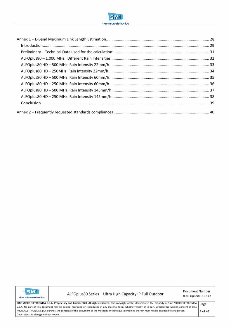
Figure 3 – ALFOplus80HD: ATPC and ACM interaction, according to hop attenuation
Throughput (1)
An Adaptive Modulation radio link throughput always depends on current modulation and on configuration and
capacity; in the following table different throughput values will be specified for each configuration.
Below the maximum net radio throughput with the different configurations and channel-bandwidth
combinations:
ALFOplus80
1 GHz
4 QAM 1 Gbps
Table 3 – Radio throughput in ALFOplus80 configuration
1 Throughput is defined according to paragraph 26.1 of RFC2544.

ALFOplus80 Series – Ultra High Capacity IP Full Outdoor
Document Number
B.ALFOplus80.1.01-11
SIAE MICROELETTRONICA S.p.A. Proprietary and Confidential. All rights reserved. The copyright of this document is the property of SIAE MICROELETTRONICA
S.p.A. No part of this document may be copied, reprinted or reproduced in any material form, whether wholly or in part, without the written consent of SIAE
MICROELETTRONICA S.p.A. Further, the contents of this document or the methods or techniques contained therein must not be disclosed to any person.
Data subject to change without notice.
Page
16 of 41
ALFOplus80HD
250MHz 500MHz
4 QAM-HB 125 Mbps 237 Mbps
4 QAM-ST 251 Mbps 474 Mbps
4 QAM 336 Mbps 637 Mbps
16 QAM-ST 502 Mbps 950 Mbps
16 QAM 673 Mbps 1.274 Mbps
64QAM 1.012 Mbps 1.915Mbps
Table 4 – Radio throughput in ALFOplus80HD configuration
To be noted that the carried throughput can achieve really higher capacities, thanks to the Packet Header
Compression technology, compressing in an efficient way all following protocol structure:
C-Tag, Multiple s-Tags , MACinMAC , multiple MPLS Labels, IPv6, UDP, RTP.
For a complete description of the Packet Header Compressor, please refer to Header Compression chapter.

ALFOplus80 Series – Ultra High Capacity IP Full Outdoor
Document Number
B.ALFOplus80.1.01-11
SIAE MICROELETTRONICA S.p.A. Proprietary and Confidential. All rights reserved. The copyright of this document is the property of SIAE MICROELETTRONICA
S.p.A. No part of this document may be copied, reprinted or reproduced in any material form, whether wholly or in part, without the written consent of SIAE
MICROELETTRONICA S.p.A. Further, the contents of this document or the methods or techniques contained therein must not be disclosed to any person.
Data subject to change without notice.
Page
17 of 41
Ethernet features
SIAE MICROELETTRONICA ALFOplus80 maps Ethernet straight into the radio frames (Native IP), this approach
provides a point-to-point unacknowledged connectionless service over the radio channel. A CRC is added to
prevent wrong packets being forwarded.
In case of 2.5Gbps usage, to be noted that the Ethernet can also be natively transported in a proprietary frame
flow, directly built at base-band stage (e.g. in the AGS-H) and directly modulated in RF frequency.
Ethernet Interface characteristics
The ALFOplus80 implements a multi-port store-and-forward Layer2 Switch. The embedded Switch supports the
following Layer2 functionalities:
MAC switching
MAC Address learning and ageing
Auto negotiation
MDI/MDIX crossover
Automatic MDI/MDIX crossover is supported; it allows NIC-to-SWITCH and SWITCH-to-SWITCH
connection regardless of cable type (straight-through or crossover).
Layer 2 Flow Control / Back Pressure
SIAE MICROELETTRONICA implements flow control based on IEEE 802.3x (full-duplex operation) and Back
Pressure (half-duplex operation) to prevent packet loss during traffic peak.
IEEE 802.1q VLANs and VLAN stacking (Q in Q)
Quality of Service
ITU-T Y.1731 ETH OAM / IEEE 802.1ag

ALFOplus80 Series – Ultra High Capacity IP Full Outdoor
Document Number
B.ALFOplus80.1.01-11
SIAE MICROELETTRONICA S.p.A. Proprietary and Confidential. All rights reserved. The copyright of this document is the property of SIAE MICROELETTRONICA
S.p.A. No part of this document may be copied, reprinted or reproduced in any material form, whether wholly or in part, without the written consent of SIAE
MICROELETTRONICA S.p.A. Further, the contents of this document or the methods or techniques contained therein must not be disclosed to any person.
Data subject to change without notice.
Page
18 of 41
Enhanced Ethernet Characteristics
EVPN profiling
o Bandwidth limiting per VLAN
o Bandwidth limiting per priority.
o Frame fragmentation
o VLAN rewriting
Hard limiting or WRED algorithms (software selectable)
Enhanced Ethernet prioritization based on MPLS “Exp bits”
Selective QinQ based on VLAN and 802.1p priority
VLAN rewriting (Radio side)
8 queues Ethernet scheduler towards radio interface
Layer2 and Layer1 link aggregation
M-STP (Multiple Spanning Tree Protocol) support up to 4 instances
Ciphering (AES)
Selective RMON on VLAN basis
G.8264 (“Distribution of timing information through packet networks ”) support
Ethernet Resiliency
LLF - Link Loss Forwarding – In order to propagate the information that a local traffic connection is discarded or
faulted to the remote equipment in order to let it be aware of this (similar to AIS alarm available for E1
TDM interface)
PIRL - Peak Input Rate Limiting - In order to control the traffic flows incoming the equipment and thus the
network, this access limitation /control policies is introduced with a “leaky bucket architecture”
G.8032 ERP – Ethernet Ring Protection – In order to provide fast protection switching (<50ms) by integrating
mature Ethernet operations, administration, and maintenance (OAM) functions and a simple automatic
protection switching (APS) protocol for Ethernet ring networks. In addition, since Ethernet, and thus ERP, is

ALFOplus80 Series – Ultra High Capacity IP Full Outdoor
Document Number
B.ALFOplus80.1.01-11
SIAE MICROELETTRONICA S.p.A. Proprietary and Confidential. All rights reserved. The copyright of this document is the property of SIAE MICROELETTRONICA
S.p.A. No part of this document may be copied, reprinted or reproduced in any material form, whether wholly or in part, without the written consent of SIAE
MICROELETTRONICA S.p.A. Further, the contents of this document or the methods or techniques contained therein must not be disclosed to any person.
Data subject to change without notice.
Page
19 of 41
virtually agnostic to all physical/server layer technologies, it can be supported any carrier’s network
infrastructure. Optimized for ring topologies, it can be applied in any Network topology, and in it also
providing multiple E-Services (e.g., E-LINE, E-TREE, E-LAN)
ELP - Ethernet Link Protection - ELP is used to protect the network from Ethernet link failures in various network
topologies and application
LAG - Link Aggregation – is a recommendation (802.1ax-2008 or 802.3ad) designed for using multiple media in
parallel to increase the link speed beyond the limits of any one single medium and increase the redundancy
for higher availability
QoS management
QoS refers to the ability of a network device to provide improved services to selected network traffic over various
underlying technologies, including Ethernet and wireless LANs. In particular, QoS feature provides an improved
and more predictable network services, as follows:
Improving loss characteristics
Avoiding and managing network congestion
Prioritizing services to different kinds of network traffic
Optimization for packet delay variation (PDV)
Setting traffic priorities and end-to-end quality management
QoS is implemented in SIAE MICROELETTRONICA products in a multilevel approach:
VLAN per port
Layer2 VLAN identifiers (802.1Q)
Layer2 priority bits (802.1P QoS)
Layer3 priorities IPv4 (ToS or DSCP) or IPv6 (TC)
Frame prioritization based on MPLS “EXP bits”

ALFOplus80 Series – Ultra High Capacity IP Full Outdoor
Document Number
B.ALFOplus80.1.01-11
SIAE MICROELETTRONICA S.p.A. Proprietary and Confidential. All rights reserved. The copyright of this document is the property of SIAE MICROELETTRONICA
S.p.A. No part of this document may be copied, reprinted or reproduced in any material form, whether wholly or in part, without the written consent of SIAE
MICROELETTRONICA S.p.A. Further, the contents of this document or the methods or techniques contained therein must not be disclosed to any person.
Data subject to change without notice.
Page
20 of 41
Layer2 priorities
Priority queues are introduced on switches output ports. 802.1p describes 8 priority levels, mapped onto 8
output queues.
A typical mapping scheme is shown below.
802.1p priority levels Traffic type Used queue
0 Best Effort 0
1 Background 1
2 NOT DEFINED 2
3 Excellent Effort 3
4 Controlled Load 4
5 Video ( latency 100 msec ) 5
6 Voice ( latency 10 msec ) 6
7 Network Control 7
Table 5 – 802.1p priorities and queues distribution
Two scheduling algorithms are available in SIAE MICROELETTRONICA equipment: strict priority or weighted
scheduling WFQ (SW selectable).
Strict Priority means that Higher priority queues are emptied first
Weighted scheduling (WFQ) means that queues are served proportionally to their configurable weights
(from 1 to 100)
Mixed Strict Priority and WFQ

ALFOplus80 Series – Ultra High Capacity IP Full Outdoor
Document Number
B.ALFOplus80.1.01-11
SIAE MICROELETTRONICA S.p.A. Proprietary and Confidential. All rights reserved. The copyright of this document is the property of SIAE MICROELETTRONICA
S.p.A. No part of this document may be copied, reprinted or reproduced in any material form, whether wholly or in part, without the written consent of SIAE
MICROELETTRONICA S.p.A. Further, the contents of this document or the methods or techniques contained therein must not be disclosed to any person.
Data subject to change without notice.
Page
21 of 41
IEEE 802.1Q VLANs
Virtual LAN (VLAN) support is the ability to logically break a LAN into a few smaller LANs and prevent data from
flowing between the sub-LANs.
VLANs can be activated in three different ways:
Based on Port. A packet belongs to a particular VLAN, depending on the local port ID. This means that
each packet received on a specific port will be forwarded only to the ports belonging to the same VLAN.
Based on IEEE 802.1Q TAG. A packet belongs to a particular VLAN, depending on its VLAN ID, defined by
the VID (VLAN Identifier) TAG content.
Hybrid. It is a mix of previous ones. Locally configured tagged frames are managed according IEEE 802.1Q
TAG, all others follow port rules.
SIAE MICROELETTRONICA equipment can also be configured to add a VLAN tag (VD and user priority) to untagged
traffic.
SIAE MICROELETTRONICA products support VLAN stacking (QinQ). This means that if input traffic is 802.1Q
compliant – i.e. VLANs are implemented – it is possible to create other VLAN inserting 4 additional bytes in
Ethernet header for traffic switching and QoS purposes.
VLAN stacking (also named QinQ) is a feature that allows an Ethernet frame to include more than one IEEE
802.1Q TAG. The scope of VLAN staking is to differentiate the traffic at different levels when the packets must
cross networks managed by different entities.
SIAE MICROELETTRONICA radio systems supports the VLAN stacking. Once a packet comes into the radio, it is
possible to add a new IEEE 802.1Q TAG with an ID depending from the port, from VLAN or type of service. Of
course, at egress side it is possible to remove such additional VLAN tag, making transport totally transparent.

ALFOplus80 Series – Ultra High Capacity IP Full Outdoor
Document Number
B.ALFOplus80.1.01-11
SIAE MICROELETTRONICA S.p.A. Proprietary and Confidential. All rights reserved. The copyright of this document is the property of SIAE MICROELETTRONICA
S.p.A. No part of this document may be copied, reprinted or reproduced in any material form, whether wholly or in part, without the written consent of SIAE
MICROELETTRONICA S.p.A. Further, the contents of this document or the methods or techniques contained therein must not be disclosed to any person.
Data subject to change without notice.
Page
22 of 41
Header compression
SIAE MICROELETTRONICA has developed a two level header compressor that is able to hash L2, L2.5, L3 and L4
header’s protocols and thus massively increase the available radio throughput.
The packet compression gain provided is from 3% up to 200% , depending on payload, protocols stacks and
packet size.
In the following figure, supported Header Compression protocol and various compression rates are reported, in
relation with packet sizes compressed protocol stacks.
Figure 4 - Layers involved in the Header compression process
The embedded compression technology can be configured in two working modes, as follows:
Basic configuration:
Packet compression supporting header combinations up to 68 bytes (Eth + MPLS + IP/UDP + RTP/GTP)
Deep/IP tunneling configuration:
Packet compression supporting header combinations up to 128 bytes (Ethernet + MPLS + IP/UDP +
RTP/GTP with additional IPv4/IPv6 tunneling)
Of course, the compression gain depends on following two fundamental factors:
Frame size
Protocol structure
As shown in following graphics, the compression gain can be higher especially with small size frames and with the
most complete protocol stack (“the more protocols, the more compression”)

ALFOplus80 Series – Ultra High Capacity IP Full Outdoor
Document Number
B.ALFOplus80.1.01-11
SIAE MICROELETTRONICA S.p.A. Proprietary and Confidential. All rights reserved. The copyright of this document is the property of SIAE MICROELETTRONICA
S.p.A. No part of this document may be copied, reprinted or reproduced in any material form, whether wholly or in part, without the written consent of SIAE
MICROELETTRONICA S.p.A. Further, the contents of this document or the methods or techniques contained therein must not be disclosed to any person.
Data subject to change without notice.
Page
23 of 41
Compression Gain
Figure 5 - Relation between packets size and compression ratio
ALFOplus80 Series – Ultra High Capacity IP Full Outdoor
Document Number
B.ALFOplus80.1.01-11
SIAE MICROELETTRONICA S.p.A. Proprietary and Confidential. All rights reserved. The copyright of this document is the property of SIAE MICROELETTRONICA
S.p.A. No part of this document may be copied, reprinted or reproduced in any material form, whether wholly or in part, without the written consent of SIAE
MICROELETTRONICA S.p.A. Further, the contents of this document or the methods or techniques contained therein must not be disclosed to any person.
Data subject to change without notice.
Page
24 of 41
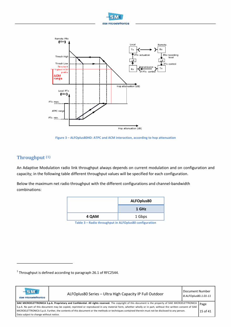
Synchronization
Synchronization unit supports following functionalities:
Synchronism source selection
Quality estimation based on frequency
Quality estimation based on information as per G.8264 standard.
Synchronism can be sourced from the incoming Ethernet flows (Synchronous Ethernet) and transported toward
remote terminal by using the symbol rate.
Remote terminal can be therefore synchronized with the received symbol rate and synchronism is distributed to
all egress Ethernet ports.
Management System
Supervision Interfaces ALFOplus80 can be reached from network management system perspective either by establishing a DCN data
channel over the Ethernet traffic interface (InBand management) or by provisioning a dedicated Ethernet port for
management purpose (Out of band management)
InBand management uses a logical separation between payload traffic and DCN traffic using specific VLAN tag
dedicated to supervision traffic.
Network Management System As for any SIAE MICROELETTRONICA network element, ALFOplus80 is provided with an embedded SNMP agent
fully compatible with existing SIAE’s Network Management Systems (NMS5-LX/UX) and relevant management
tools.
Secured Connections to Network Element Secure protocols are supported to connect the NE:
Security management (SSH, SFTP) on equipment
Secure HTTP access (HTTPS) on equipment
SNMP V3

ALFOplus80 Series – Ultra High Capacity IP Full Outdoor
Document Number
B.ALFOplus80.1.01-11
SIAE MICROELETTRONICA S.p.A. Proprietary and Confidential. All rights reserved. The copyright of this document is the property of SIAE MICROELETTRONICA
S.p.A. No part of this document may be copied, reprinted or reproduced in any material form, whether wholly or in part, without the written consent of SIAE
MICROELETTRONICA S.p.A. Further, the contents of this document or the methods or techniques contained therein must not be disclosed to any person.
Data subject to change without notice.
Page
25 of 41
Mechanical Layout
Integrated antenna solutions The ALFOplus80 is provided as integrated antenna solution, as well as in 80GHz frequency band is not even
possible a separated antenna installation.
Applicable antenna diameters are 0.2mt, 0.3mt and 0.6mt. Bigger antennas are not in field applicable for pointing
and alignment in field constraints.
Figure 6 – ALFOplus80 with integrated 0.3mt antenna.
Weight 1
System Version Weight(kg)
ALFOplus80 4.5
Physical Dimensions of system components 1
System Version Width (mm) Height (mm) Depth (mm)
ALFOplus80 270 270 67,6
For a more complete dimensions description, please refer to here below figure.
1 Data subject to change.

ALFOplus80 Series – Ultra High Capacity IP Full Outdoor
Document Number
B.ALFOplus80.1.01-11
SIAE MICROELETTRONICA S.p.A. Proprietary and Confidential. All rights reserved. The copyright of this document is the property of SIAE MICROELETTRONICA
S.p.A. No part of this document may be copied, reprinted or reproduced in any material form, whether wholly or in part, without the written consent of SIAE
MICROELETTRONICA S.p.A. Further, the contents of this document or the methods or techniques contained therein must not be disclosed to any person.
Data subject to change without notice.
Page
26 of 41
Figure 7 – ALFOplus80 physical dimensions

ALFOplus80 Series – Ultra High Capacity IP Full Outdoor
Document Number
B.ALFOplus80.1.01-11
SIAE MICROELETTRONICA S.p.A. Proprietary and Confidential. All rights reserved. The copyright of this document is the property of SIAE MICROELETTRONICA
S.p.A. No part of this document may be copied, reprinted or reproduced in any material form, whether wholly or in part, without the written consent of SIAE
MICROELETTRONICA S.p.A. Further, the contents of this document or the methods or techniques contained therein must not be disclosed to any person.
Data subject to change without notice.
Page
27 of 41
Technical Characteristics
Power supply
Range
-40.8 -57.6 VDC According to ETSI EN300132-2
Power Consumption (W)
Configuration ALFOplus80
ALFOplus80 radio terminal ≤ 33
Environmental conditions
Environmental Conditions Range
Protection Class for ODU IP65
Wind load 200 km/h
Surge and lightning protection according to ETSI EN 301 489
Temperature range -33°C ÷ +55°C
ALFOplus80 Series – Ultra High Capacity IP Full Outdoor
Document Number
B.ALFOplus80.1.01-11
SIAE MICROELETTRONICA S.p.A. Proprietary and Confidential. All rights reserved. The copyright of this document is the property of SIAE MICROELETTRONICA
S.p.A. No part of this document may be copied, reprinted or reproduced in any material form, whether wholly or in part, without the written consent of SIAE
MICROELETTRONICA S.p.A. Further, the contents of this document or the methods or techniques contained therein must not be disclosed to any person.
Data subject to change without notice.
Page
28 of 41
Annex 1 – E-Band
Maximum Link
Length Estimation

ALFOplus80 Series – Ultra High Capacity IP Full Outdoor
Document Number
B.ALFOplus80.1.01-11
SIAE MICROELETTRONICA S.p.A. Proprietary and Confidential. All rights reserved. The copyright of this document is the property of SIAE MICROELETTRONICA
S.p.A. No part of this document may be copied, reprinted or reproduced in any material form, whether wholly or in part, without the written consent of SIAE
MICROELETTRONICA S.p.A. Further, the contents of this document or the methods or techniques contained therein must not be disclosed to any person.
Data subject to change without notice.
Page
29 of 41
Introduction
An important aspect regarding “E-band” equipments, and so ALFOplus80, is the link length which can be achieved
in the 80GHz frequencies, considering applicable link availabilities and “reasonable” antenna dimensions –
meaning usable in field, in real application cases.
In fact, to be taken into account is that no antennas bigger than 0.6mt diameter are used, just because of the too
much thin RPE main beam. With this kind of beam, a fixed pointing of the antennas is possible only up 0.6mt;
beyond the pointing is really hard to be achieved and –much more important- cannot be maintained during the
time of the “in field application”.
The purpose of this annex is to provide an estimation of the maximum distances that can be achieved with radio
equipments transmitting in the “E-band” with ALFOplus80.
These calculations have been performed considering:
Vertical Polarization;
A tolerance of 1 dB has been taken into account;
Maximum Transmit Power Attenuation (ATPC range): 20dB
The performances for each link have been performed considering each link lacking of interference.
The performances for each link have been performed considering clear LOS between the terminal sites.
The links performances degradations due to ducting and other anomalous propagation phenomenon has
not been taken into account.
The following calculations must be considered as a preliminary analysis. Real maximum link distance
calculation could differ from the data present below
The calculations have been performed with the following variables combinations:
Rain Intensity of: 22mm/h – 35mm/h – 42mm/h – 60mm/h – 95mm/h – 145mm/h
Channel BW: 250 MHz – 500 MHz and 1 GHz
Modulation: 4 QAM Half-Band – 4 QAM Strong – 4 QAM – 16 QAM Strong - 16 QAM – 64 QAM
Antennas: It has been supposed the availability of 0.2m – 0.3m – 0.6m models
Availability Objectives: 99.999% - 99.995% - 99.99%

ALFOplus80 Series – Ultra High Capacity IP Full Outdoor
Document Number
B.ALFOplus80.1.01-11
SIAE MICROELETTRONICA S.p.A. Proprietary and Confidential. All rights reserved. The copyright of this document is the property of SIAE MICROELETTRONICA
S.p.A. No part of this document may be copied, reprinted or reproduced in any material form, whether wholly or in part, without the written consent of SIAE
MICROELETTRONICA S.p.A. Further, the contents of this document or the methods or techniques contained therein must not be disclosed to any person.
Data subject to change without notice.
Page
30 of 41
The calculations have been performed considering the two different configurations of the ALFOplus80:
SIAE ALFOplus80 HD: for channel bandwidth of 250 MHz and 500MHz (Modulations: All above)
SIAE ALFOplus80: for channel bandwidth of 1 GHz (Modulation: 4QAM, Tx power: 18 dBm)
Note: Considering the official ETSI mask, the ALFOplus80’s TX power has been tested and verified up to
22dBm, complying with all relevant ETSI recommendations.
The 18dBm value only refers to a more conservative draft ETSI mask, which today is in a discussion
stage.
Finally, the calculations have been performed considering following two different ATPC modes
ATPC Disabled: when required, the link is working with fixed transmit power attenuation in order to not
exceed the maximum input RX level. The output power remains fixed, independently from the
propagation conditions.
ATPC Enabled: In nominal conditions (without rain fading) the link can work with a reduced output power,
in order to not exceed the maximum input RX level. In case of rain fading, the output power can be
dynamically increased up to the maximum value in order to increase the link performances.
A complete case set of all the possible combination can be provide in a separate document; in this annex only the
most significant cases are reported, in order to present the applicability range of such technology and frequency.

ALFOplus80 Series – Ultra High Capacity IP Full Outdoor
Document Number
B.ALFOplus80.1.01-11
SIAE MICROELETTRONICA S.p.A. Proprietary and Confidential. All rights reserved. The copyright of this document is the property of SIAE MICROELETTRONICA
S.p.A. No part of this document may be copied, reprinted or reproduced in any material form, whether wholly or in part, without the written consent of SIAE
MICROELETTRONICA S.p.A. Further, the contents of this document or the methods or techniques contained therein must not be disclosed to any person.
Data subject to change without notice.
Page
31 of 41
Preliminary – Technical Data used for the calculation:
Antennas [m] Gain [dBi]
0.2 40.0
0.3 43.0
0.6 50.0
Equipment Channel BW
[MHz] Modulation
TX Power
[dBm]
Thresold Power
[dBm]
Net Radio
Throughput
ALFOplus80 1000 4QAM 18 -63 1000Mbit/s
ALFOplus80
HD
250
4QAM-HB 18 -73 125 Mbit/s
4sQAM 18 -70 251 Mbit/s
4QAM 18 -67 336 Mbit/s
16sQAM 15 -62 502 Mbit/s
16QAM 15 -59 673 Mbit/s
64QAM 13 -54 1012 Mbit/s
500
4QAM-HB 18 -70 237 Mbit/s
4sQAM 18 -67 474 Mbit/s
4QAM 18 -64 637 Mbit/s
16sQAM 15 -59 950 Mbit/s
16QAM 15 -56 1274 Mbit/s
64QAM 13 -51 1915 Mbit/s
NOTE: Equipment parameters could be subject to future refinement. Antenna diameter availability and gain
figures to be confirmed by antenna suppliers.

ALFOplus80 Series – Ultra High Capacity IP Full Outdoor
Document Number
B.ALFOplus80.1.01-11
SIAE MICROELETTRONICA S.p.A. Proprietary and Confidential. All rights reserved. The copyright of this document is the property of SIAE MICROELETTRONICA
S.p.A. No part of this document may be copied, reprinted or reproduced in any material form, whether wholly or in part, without the written consent of SIAE
MICROELETTRONICA S.p.A. Further, the contents of this document or the methods or techniques contained therein must not be disclosed to any person.
Data subject to change without notice.
Page
32 of 41
ALFOplus80 – 1.000 MHz: Different Rain Intensities
Table 6: ALFOplus80 - BW = 1000MHz – Rain= 22 to 42 mm/h – ATPC Enabled
Table 7: ALFOplus80 - BW = 1000MHz – Rain= 22 to 42 mm/h – ATPC Disabled

ALFOplus80 Series – Ultra High Capacity IP Full Outdoor
Document Number
B.ALFOplus80.1.01-11
SIAE MICROELETTRONICA S.p.A. Proprietary and Confidential. All rights reserved. The copyright of this document is the property of SIAE MICROELETTRONICA
S.p.A. No part of this document may be copied, reprinted or reproduced in any material form, whether wholly or in part, without the written consent of SIAE
MICROELETTRONICA S.p.A. Further, the contents of this document or the methods or techniques contained therein must not be disclosed to any person.
Data subject to change without notice.
Page
33 of 41
ALFOplus80 HD – 500 MHz: Rain Intensity 22mm/h
Table 8: ALFOplus80Plus - BW = 500MHz – MOD = 4QAM-hb to 4QAM - ATPC Enabled
Table 9: ALFOplus80Plus - BW = 500MHz – MOD = 16QAM-st to 64QAM - ATPC Enabled
Table 10: ALFOplus80Plus - BW = 500MHz – MOD = 4QAM-HB to 4QAM - ATPC Disabled
Table 11: ALFOplus80Plus - BW = 500MHz – MOD = 16QAM-st to 64QAM - ATPC Disabled

ALFOplus80 Series – Ultra High Capacity IP Full Outdoor
Document Number
B.ALFOplus80.1.01-11
SIAE MICROELETTRONICA S.p.A. Proprietary and Confidential. All rights reserved. The copyright of this document is the property of SIAE MICROELETTRONICA
S.p.A. No part of this document may be copied, reprinted or reproduced in any material form, whether wholly or in part, without the written consent of SIAE
MICROELETTRONICA S.p.A. Further, the contents of this document or the methods or techniques contained therein must not be disclosed to any person.
Data subject to change without notice.
Page
34 of 41
ALFOplus80 HD – 250MHz: Rain Intensity 22mm/h
Table 12: ALFOplus80Plus - BW = 250MHz – MOD = 4QAM-hb to 4QAM – ATPC Enabled
Table 13: ALFOplus80Plus - BW = 250MHz – MOD = 16QAM-st to 64QAM - ATPC Enabled
Table 14: ALFOplus80Plus - BW = 250MHz – MOD = 4QAM-hb to 4QAM - ATPC Disabled
Table 15: ALFOplus80Plus - BW = 250MHz – MOD = 16QAM-st to 64QAM - ATPC Disabled

ALFOplus80 Series – Ultra High Capacity IP Full Outdoor
Document Number
B.ALFOplus80.1.01-11
SIAE MICROELETTRONICA S.p.A. Proprietary and Confidential. All rights reserved. The copyright of this document is the property of SIAE MICROELETTRONICA
S.p.A. No part of this document may be copied, reprinted or reproduced in any material form, whether wholly or in part, without the written consent of SIAE
MICROELETTRONICA S.p.A. Further, the contents of this document or the methods or techniques contained therein must not be disclosed to any person.
Data subject to change without notice.
Page
35 of 41
ALFOplus80 HD – 500 MHz: Rain Intensity 60mm/h
Table 16: ALFOplus80Plus - BW = 250MHz – MOD = 4QAM-hb to 4QAM – ATPC Enabled
Table 17: ALFOplus80Plus - BW = 250MHz – MOD = 16QAM-st to 64QAM – ATPC Enabled
Table 18: ALFOplus80Plus - BW = 500MHz – MOD = 4QAM-hb to 4QAM - ATPC Disabled
Table 19: ALFOplus80Plus - BW = 500MHz – MOD = 16QAM-st to 64QAM - ATPC Disabled
ALFOplus80 Series – Ultra High Capacity IP Full Outdoor
Document Number
B.ALFOplus80.1.01-11
SIAE MICROELETTRONICA S.p.A. Proprietary and Confidential. All rights reserved. The copyright of this document is the property of SIAE MICROELETTRONICA
S.p.A. No part of this document may be copied, reprinted or reproduced in any material form, whether wholly or in part, without the written consent of SIAE
MICROELETTRONICA S.p.A. Further, the contents of this document or the methods or techniques contained therein must not be disclosed to any person.
Data subject to change without notice.
Page
36 of 41
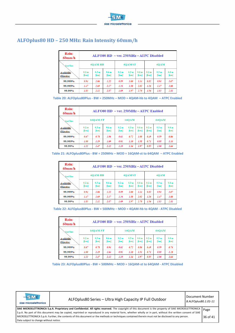
ALFOplus80 HD – 250 MHz: Rain Intensity 60mm/h
Table 20: ALFOplus80Plus - BW = 250MHz – MOD = 4QAM-hb to 4QAM – ATPC Enabled
Table 21: ALFOplus80Plus - BW = 250MHz – MOD = 16QAM-st to 64QAM – ATPC Enabled
Table 22: ALFOplus80Plus - BW = 500MHz – MOD = 4QAM-hb to 4QAM - ATPC Disabled
Table 23: ALFOplus80Plus - BW = 500MHz – MOD = 16QAM-st to 64QAM - ATPC Disabled

ALFOplus80 Series – Ultra High Capacity IP Full Outdoor
Document Number
B.ALFOplus80.1.01-11
SIAE MICROELETTRONICA S.p.A. Proprietary and Confidential. All rights reserved. The copyright of this document is the property of SIAE MICROELETTRONICA
S.p.A. No part of this document may be copied, reprinted or reproduced in any material form, whether wholly or in part, without the written consent of SIAE
MICROELETTRONICA S.p.A. Further, the contents of this document or the methods or techniques contained therein must not be disclosed to any person.
Data subject to change without notice.
Page
37 of 41
ALFOplus80 HD – 500 MHz: Rain Intensity 145mm/h
Table 24: ALFOplus80Plus - BW = 250MHz – MOD = 4QAM-hb to 4QAM – ATPC Enabled
Table 25: ALFOplus80Plus - BW = 250MHz – MOD = 16QAM-st to 64QAM – ATPC Enabled
Table 26: ALFOplus80Plus - BW = 500MHz – MOD = 4QAM-hb to 4QAM - ATPC Disabled
Table 27: ALFOplus80Plus - BW = 500MHz – MOD = 16QAM-st to 64QAM - ATPC Disabled

ALFOplus80 Series – Ultra High Capacity IP Full Outdoor
Document Number
B.ALFOplus80.1.01-11
SIAE MICROELETTRONICA S.p.A. Proprietary and Confidential. All rights reserved. The copyright of this document is the property of SIAE MICROELETTRONICA
S.p.A. No part of this document may be copied, reprinted or reproduced in any material form, whether wholly or in part, without the written consent of SIAE
MICROELETTRONICA S.p.A. Further, the contents of this document or the methods or techniques contained therein must not be disclosed to any person.
Data subject to change without notice.
Page
38 of 41
ALFOplus80 HD – 250 MHz: Rain Intensity 145mm/h
Table 28: ALFOplus80Plus - BW = 250MHz – MOD = 4QAM-hb to 4QAM - ATPC Enabled
Table 29: ALFOplus80Plus - BW = 250MHz – MOD = 16QAM-st to 64QAM – ATPC Enabled
Table 30: ALFOplus80Plus - BW = 500MHz – MOD = 4QAM-hb to 4QAM - ATPC Disabled
Table 31: ALFOplus80Plus - BW = 500MHz – MOD = 16QAM-st to 64QAM - ATPC Disabled

ALFOplus80 Series – Ultra High Capacity IP Full Outdoor
Document Number
B.ALFOplus80.1.01-11
SIAE MICROELETTRONICA S.p.A. Proprietary and Confidential. All rights reserved. The copyright of this document is the property of SIAE MICROELETTRONICA
S.p.A. No part of this document may be copied, reprinted or reproduced in any material form, whether wholly or in part, without the written consent of SIAE
MICROELETTRONICA S.p.A. Further, the contents of this document or the methods or techniques contained therein must not be disclosed to any person.
Data subject to change without notice.
Page
39 of 41
Conclusion
The maximum distance varies from about 5.5 km in the best scenario (22mm/h – 4QAM-HB – 0.6m diameter -
99.99 % of availability) to about 0.3 km for worst cases (145 mm/h -64QAM – 0.2 m diameter – 99.999% of
availability).
The use of ATPC can help, for the most critical cases (i.e. high rain intensity and/or performances), to increase the
links’ lengths, since it allow the link to suffer from deeper field attenuations.
In most cases, however, the same maximum link length can be achieved with both fixed attenuation and ATPC.

ALFOplus Series – High Capacity IP Full Outdoor
Brochure
Document Number
B. ALFOplus.1.03-11
SIAE MICROELETTRONICA S.p.A. Proprietary and Confidential. All rights reserved. The copyright of this document is the property of SIAE MICROELETTRONICA
S.p.A. No part of this document may be copied, reprinted or reproduced in any material form, whether wholly or in part, without the written consent of SIAE
MICROELETTRONICA S.p.A. Further, the contents of this document or the methods or techniques contained therein must not be disclosed to any person.
Data subject to change without notice.
Page
40 of 41
Annex 2 – Frequently requested standards compliances
EN 300 132-2 Power supply interface at the input to telecommunications equipment
EN 300 019 Environmental conditions and environmental tests for telecommunications equipment
(Operation: class 3.2 for IDU and class 4.1 for ODU; storage: class 1.2; transport: class
2.3)
EN 301 390 Fixed Radio Systems; Point-to-point and Point-to-Multipoint Systems; Spurious
emissions and receiver immunity at equipment/antenna port of Digital Fixed Radio
System
EN 302 217 Characteristics and requirements for point-to-point equipment and antenna
EN 301 489 Electromagnetic Compatibility (EMC) standard for radio equipment and services
EN 60950 Information Technology Equipment – Safety
ITU-R ITU Recommendations for all frequency bands
ITU-R F.1191 Bandwidths and unwanted emissions of digital fixed service systems
CEPT CEPT Recommendations for all frequency bands
IEE 802 802.1ag (Connectivity Fault Management), 802.1p (QoS), 802.1Q (VLAN), 802.1W
(RSTP), 802.3ad-2008 (link aggregation), 802.3i (10BASE-T), 802.3u (100BASE-TX/FX),
802.3x (Flow control), 802.3ab (1000 BASE-T), 802.3z (1000BASE LX/SX)
IEEE 1588-2008 Standard for a Precision Clock Synchronization Protocol for Networked Measurement
and Control Systems
ITU-T 1731 Ethernet OAM fault management
ITU-T G.8261 Timing and Synchronization Aspects in Packet Networks
ITU-T G.8262 Characteristics of synchronous Ethernet Equipment slave Clock
ITU-T G.8264 Distribution of timing through packet networks