Embed Size (px)
Citation preview

Alejandro Cardesín MoineloESA Science Operations(slides courtesy of Christian Erd & Peter Falkner, ESA-ESTEC)
IAC Winter School, Nov 2016

Slide 2
Mission Flow Diagram

Slide 3
Space Mission Timeline: Phases
Slide 4
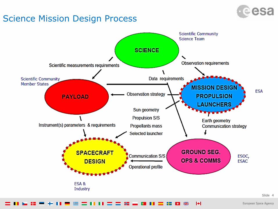
Science Mission Design Process

Slide 5
Science Objectives – Requirements - Solutions
Science Objective is the high level motivation• Which scientific question/application purpose shall the
project address and what answer is sought
Requirement is the translation of this objective into verifiable statements of what is needed to achieve the objective
• With detailed quantities (unambiguous)• Several levels of detail• Traceable, all the way back to the top level• Careful with conflicting requirements
Solution is the response to the all requirements• There can be several solutions meeting requirements• Non-compliance needs to be negotiated
WHY?
WHAT?
HOW?

Slide 6
Conflicting Requirements
Farm “Optimal” Animal :
Eierlegende Wollmilchsau(famous Austrian animal)

Slide 7
Trade-off
Trade-off allows exploring alternative solutions to a baseline
Most common criteria: mass, cost budget; several system properties can be translated into them
Power consumption generation of more power solar array size mass
Higher telemetry volume larger HGA, more power for TM&C mass
High performance complex solutions more effort for verification longer integration time cost
Mass Cost
SystemPerformance

Slide 8
Mission Segments, Systems & Subsystems
Slide 9
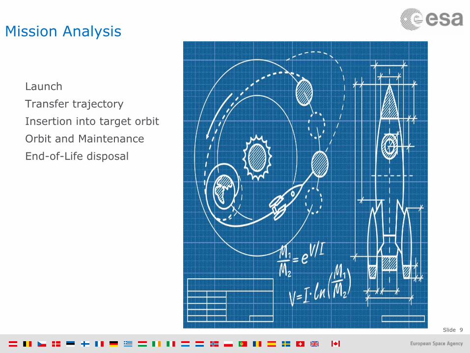
Mission Analysis
Launch Transfer trajectoryInsertion into target orbit Orbit and Maintenance End-of-Life disposal

Slide 10
Launchers
Rocket launcher gives initial impulse in order to:Compensate gravity and atmospheric dragInsertion in terrestrial orbit (Low/Medium/Geostationary)Earth Escape Velocity (11km/s, 40000km/h)Insertion into interplanetary transfer orbit
3 types of ESA launchers:Vega (35M€) : 1500kg Low Earth OrbitSoyuz-Fregat (70M€) : 3000kg GEO transferAriane 5 (150M€) : 6000-10000kg GEO transfer
Mars Express on Soyuz-FregatBaikonur 2003

Slide 11
SC size needs to fit the Launcher!Ariane 5
~4.5x10m

Slide 12
Interplanetary Transfer Orbit:Simple Hohmann transfer trajectory
Cheapest transfer ellipse between twocircular co-planar orbits:
minimum acceleration: least fuelOther trajectories may
be faster,but more expensive!

Slide 13
Lambert Problem - Cost function
Lambert Problem:In the real world the orbits of the planets are neither coplanar nor circularWe are looking for the ellipse or hyperbola which connects r1 to r2If we specify the time-of-flight(t -t = Dt), only one solution exists
Cost function:Minimize fuel consumption for departure and arrival maneuvers (dv1+dv2)
Earth-Mars Transfer : 309 daysLaunch : 31 Oct 2026Arrival Date: 6 Sep 2027

Slide 14
Lambert Problem Cost function
Earth-Mercury Transfer : 100 daysLaunch Date: Date 11 May 2025Arrival Date: Date 20 Aug 2025
Earth-Venus Transfer : 127 daysLaunch : Date 1 Jan 2025Arrival Date: Date 8 May 2025

Slide 15
Hohhman Transfer time durations from Earth
JS
U
P
N

Slide 16
Interplanetary Transfer Orbit: Other trajectories can be much more complex…
L+22.3years
L+129days
August2026
L+1.2years
L+5.9years
L+3.5years
D.S
.M.
D.S
.M.
D.S
.M.
D.S
.M.
...
Slide 17
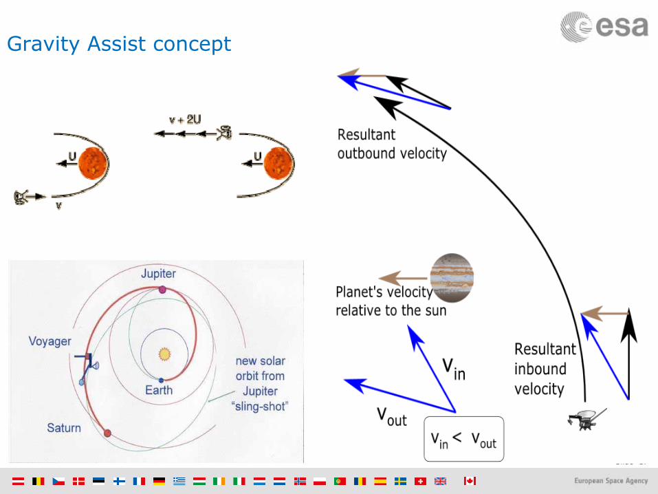
Gravity Assist concept
Slide 18
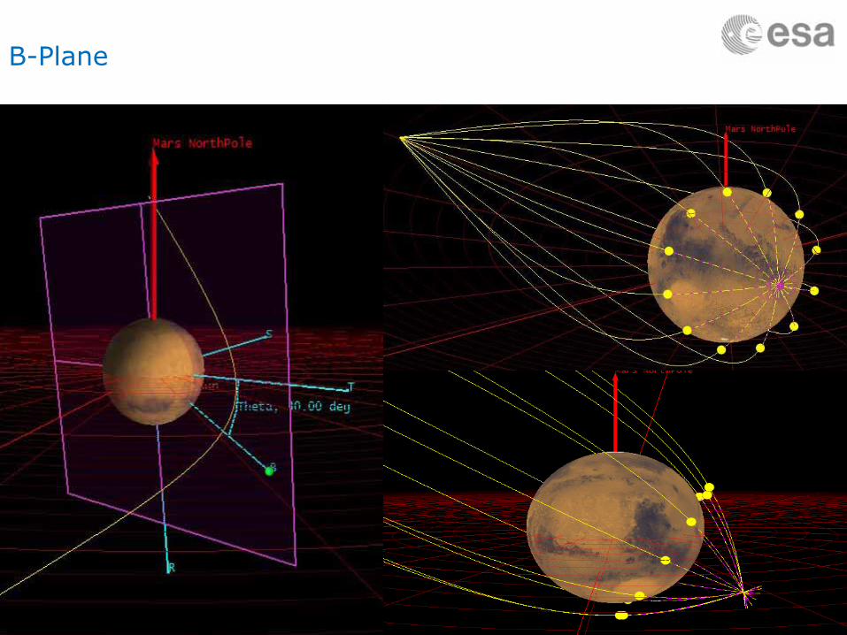
B-Plane

Slide 19
Off-plane swing-bysUlysses Polar orbit

Slide 20
Orbit Insertion
1300kg fuel (TGO)Collissiontrajectory
Lander release
Insertiontrajectory
MARS ORBIT INSERTION

Slide 21
Target orbit selection
Driven by (contradicting) requirements: Resolution, revisit time, link budgets,
ground station visibility, eclipse duration Cost of orbit acquisition and maintenance
(e.g. drag, J-term perturbations, 3rd body perturbations etc…)
Illumination conditions

Slide 22
Space EnvironmentRadiation effects electronics, materials and increase noise in detectorsSolar wind & flares: protons: 1 MeV to > 1 GeV Cosmic Rays (protons, heavy nuclei)Spacecraft charging (electric currents)Magnetic Field Solar Radiation Pressure Thermal environment Vacuum: Atomic Oxygen
Radiation belts of Earth, Jupiter,… electrons, protons
Jupiter

Slide 23
Spacecraft Sub-systems
StructurePropulsionOrientationPowerOn-board ComputerCommunicationsThermal ControlPayload

Slide 24
Structures
Primary structure(platform harness)
Secondary Structure(equipment + mechanisms)
Structure can be a large fraction of the total satellite mass: ~30 %

Slide 25
Structures

Slide 26
Mechanisms
Slide 27
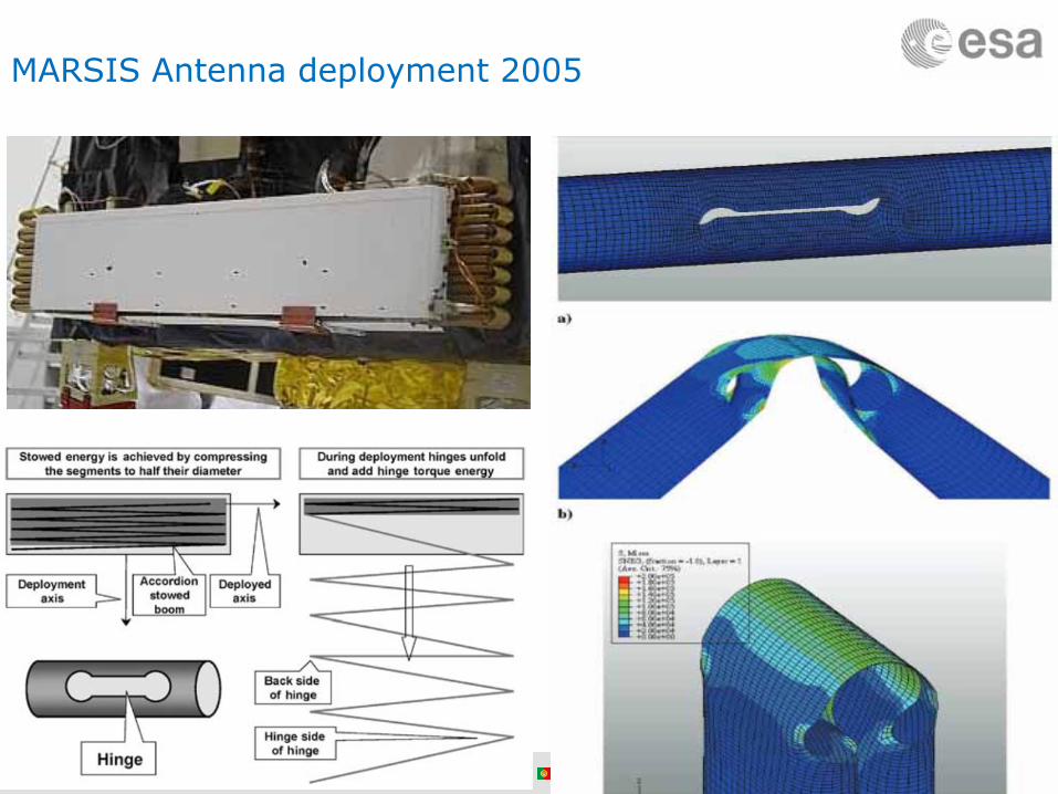
MARSIS Antenna deployment 2005

Slide 28
MARSIS Antenna deployment 2005

Slide 29
Propulsion
Subsystem in charge of satellite manoeuvring
Includes thrusters, tanks, piping and valvesMany technologies available
Solid thruster: single one off, high thrustMonopropellantBi-propellant: Solar Electric
For orbital manoeuvres with high ∆V: “high” Isp (> 300 s), e.g. bipropellant or electric propulsion
For orbital manoeuvres with low ∆V: “medium” Isp and thrust (~1 N) – e.g. monopropellant - hydrazine
For fine control: “low” thrust: (≤10 mN) – cold gas or FEEP based
Specifics for deep space missions:Pressurized tanks will be necessary (engine re-start)Valve isolation and redundancy
500 N engine
22N thruster

Slide 30
PropulsionExample (Mars Express)
Main Engine for Orbit Insertion– 1 x 400 Newtons (for ∆v=800m/s)
Thrusters for Attitude Control– 8 x 10 Newtons
Bi-propellant system– 2 tanks 270L: Oxidizer + Propellant– 1 tank 35L : Helium for pressure– 500 kg in total
30
Slide 31
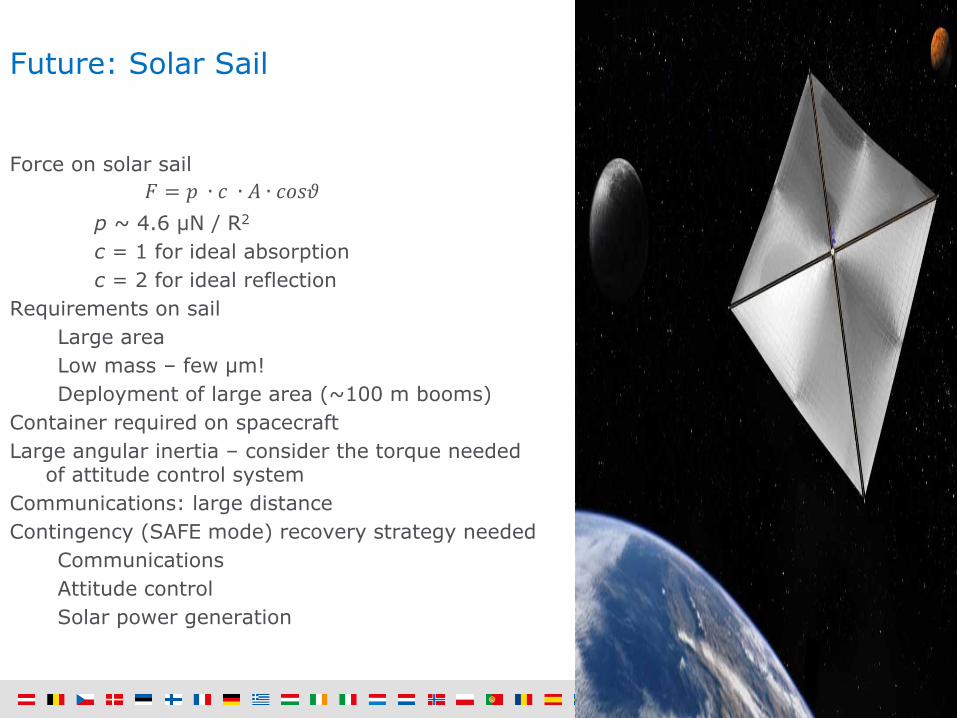
Future: Solar Sail
Force on solar sail ∙ ∙ ∙
p ~ 4.6 µN / R2
c = 1 for ideal absorptionc = 2 for ideal reflection
Requirements on sailLarge areaLow mass – few µm!Deployment of large area (~100 m booms)
Container required on spacecraftLarge angular inertia – consider the torque needed
of attitude control systemCommunications: large distanceContingency (SAFE mode) recovery strategy needed
CommunicationsAttitude controlSolar power generation

Slide 32
Propulsion Design
Propellant mass∆∙ 1
Needs to include:All deterministic manoeuvres (∆V)Navigations manoeuvres (stochastic)All AOCS needs (momentum wheel off-loading, SAFE mode, etc)
Propulsion system dry mass rule of thumb: 0.2 × Mprop

Slide 33
PropulsionReaction Control System Thrusters
Definition and location of thrusters
Thrusting in any direction in any attitude
Redundancy required
RCS Thrusters could act as backup for main engine
Messenger RCS layout

Slide 34
GNC Guidance and Navigation Control(AOCS Attitude and Orbit Control System)
Allows maintaining the desired spacecraft orientationTrade-off: spinner versus 3-axis stabilized
Composed ofSensors (to measure actual attitude)
Star trackers measure attitude wrt to inertial directions and have accuracy between 1 arcsec and 1 arcmin
Sun sensors have accuracy between 20 arcsec and 1 degGyros measure angular rates and can be used together with
Star trackers for high accuracy pointingActuators (to achieve desired attitude)
Reaction wheelsThrusters
Choice of sensors and actuators widely depends on requirements

Slide 35
GNC Guidance and Navigation Control(AOCS Attitude and Orbit Control System)
Fully redundant system , 3-axis stabilized, ∆φ <0.05deg, ω < 0.15 deg/s

Slide 36
Terminology – Pointing Error Indices
APE=absolute performance error: instantaneous pointing at the right sceneMPE=mean performance error: average pointing at the right sceneRPE=relative performance error: stability during payload integration timePRE=performance reproducibility error: overlapping of two observation seriesPDE=performance drift error: drift between repeated observationsAKE, MKE, RKE: absolute/ mean/ relative knowledge error
t: instantaneous time∆T: window time∆Ts: window stability time

Slide 37
Electrical Power Subsystem (EPS)
How Much Power Does a Spacecraft Need?
Small (Light-Bulb Sized)Mars Climate Orbiter; Mars Odyssey: 300WMars Polar Lander; Mars Exploration Rover: 150WStardust; Genesis: 200W
Medium (Hair Dryer Sized)Mars Reconnaissance Orbiter (1kW)Metereological Satellites (2kW - 5kW)Commercial & Military Communication Satellites (1kW -
15kW)
Large (House-Sized)Hubble Space Telescope (25kW)NASA / International Space Station (50kW)
Monster (City-Sized)Lunar & Martian Stations (100kW - 1MW)

Slide 38
Electrical Power Subsystem (EPS)
Provides electrical power to S/C and payload
Solar PanelsPanels need to point to the sunNeed special design or rotation mechanismSolar Flux at Earth ~1400 W/m2, at Mars ~600W/m2MEX: 11.4m2 sillicon cells ~10% eff. => ~500 Watts
(new technologies increase efficiency ~30%)
BatteryNeeded for eclipses, emergency, …MEX: Lithium-Ion battery 67 Amp hour
(60 times a normal phone battery)
Alternative Power sourcesNuclear Power (RTG, RHU’s, ASGR’s), constant power
(necessary for missions beyond Jupiter)

Slide 39
Electrical Power Subsystem (EPS)Nuclear Sources
Basically using heat generated by radioactive decay and a thermo-electric converter
DegradationHalf life: Pu (88 yrs), 241Am (433 yrs)Themo-electric element: ~0.8% /yr
Radioisotope Heating Unit (RHU)US: 1 W 40 gRus: 8 W 200 g
Name Electrical Thermal Mass
MMRTG (238Pu) 110 W 2000 W 45 kg
ASRG (238Pu) 160 W 500 W 34 kg
ESA (Am2O3) <1 W/kg

Slide 40
Communications
Earth-Spacecraft-Lander transmissionScience Data, Commands, housekeeping, Tracking (location, velocity), Radio science
Radio LinkData rate increases with antenna size and frequency, Data rate decreases with distance (MEX maximum 228kbps X-band)
At short distance low frequency is enough:S band (2 GHz), UHF (<1GHz) for lander
At longer distance higher frequency needed:X (or Ka)-band (7/32 GHz)
Spacecraft AntennaMEX High Gain Antenna 1.6m diameter X/S-bandMEX Low Gain Antenna (emergency) 20cm S-band + UHF for lander
Ground StationsESA 35m diameter: Madrid, Australia, ArgentinaNASA 35/70m diameter: Madrid, Australia, USA

Slide 41
Link Budget
Telemetry budget, receiver margin:Eb/N0 ratio of received-energy-per-bit to noise-density
TransmitterP transmitter powerLl transmitter line lossGt transmitter antenna gain (area, shape, λ–2)
TransmissionLs space loss (slant range)La transmission path loss (atmosphere,
etc)Receiver
Gr receiver antenna gainkTs system noise energy
Data rate: R
∙ ∙ ∙ ∙ ∙∙ ∙
see also in SMAD

Slide 42
HGA Performance
High Gain Antenna (HGA) versus pointing performanceOptimum antenna diameter for known AOCS off-pointingFurther iteration to be done once AOCS performance is known
Diam1
Diam2 > Diam1Pointin
P
1
2
3
4
(the
Diam1
Diam2 > Diam1Pointin
P
11
22
33
44
(the
Parabolic reflector antenna @ 32,05GHz
0,00
0,05
0,10
0,15
0,20
0,25
0,30
0,35
2 2,2 2,4 2,6 2,8 3 4 5 6
Antenna diameter [m]
Dou
ble
side
d be
amw
idth
[deg
]
51,50
52,00
52,50
53,00
53,50
54,00
54,50
55,00
55,50
56,00
Gai
n w
ith o
ff-po
intin
g [d
Bi]
3dB double sided beamwidth [deg] Gain with off-pointing of 0,1deg [dBi]see also in SMAD

Slide 43
Thermal Control Subsystem
The subsystem that allows keeping the spacecraft and payload temperatures within allowable limits
Generally, separated thermal control for spacecraft and payload due to different temperature requirements
Basic principles:Insulate the spacecraft from the environment
to keep stable temperatures inside and provide an aperture for dissipation of excess heat (radiator).
During eclipse provide heating power to keep the spacecraft warm
• thermal blankets (MLI)• external paints to modify
optical properties• radiator(s), associated
heat transport devices (heat pipes, high conductivity paths)

Slide 44
Heat sources
Thermal Control
External Temperatures -100 ~ +150oCMulti-Layer Insulator to avoid
illumination and dissipationMost electrical power is
converted into heatRadiators + Heaters + pipes…
~10º
SunPlanets
Electronics Heaters
Rosetta radiatorlouvers
Dissipation Sources
Antenna,Radar
Heat Leaks(openings)
Radiators(& louvers)

Slide 45
Thermal Control
Controls spacecraft thermal environment in various mission phases: Launch, transfer, science mode, safe mode, eclipse, etc… Driven by equipment and payload requirements Need careful analysis of all modes (internal dissipation and external input) under various aspect angles and for all mission phases.
Sensors: temperature sensors Control Components: – Coatings, MLI, paint, radiators, sun shields, foam, heat pipes, optical reflectors, louvers, fillers, thermal insulators, cooler, cold plates, phase change devices, electrical heaters & thermostats, RHU’s,…. – Using of emission (ε), absorption (α) values – Requires: Geometrical Mathematical Model (GMM) and Thermal Mathematical Model (TMM) –e.g. ESATAN – Need to understand the characteristics and dissipation of all s/c equipment
Attention to: thermo-elastics (co-alignment), outgasing

Slide 46
Thermal Design
Spacecraft Thermal verification:Assume single node and make thermal balance
ε
3. Solve first for Arad (radiator area) fixing max allowed T and optical properties – hot case
4. Solve then to find Pdissipated needed to keep T within limits in eclipse for Arad –cold case

Slide 47
On Board Data Handling (OBDH)
Data Management SystemTelecommand distributionTelemetry dataEvents, housekeeping, …
Control and Data Managament Units4 Processor Modules (2 DMS + 2 AOCS)
Bus Architecture + High speed Link
Solid State Mass MemoryPayload Data Handling Unit(MEX: 8 Gbit EXM: 1024Gbit)

Slide 48
Payload Subsystems

Slide 49
Subsystem Trade-off Tree

Slide 50
System Summary
Mission profile & lifetime
Launcher: launch mass, fairing
Budgets: Mass, Power
Total system marginEquipment 5~20% (based on TRL) Total System Level 20%
Operations, Cost, risks, schedule

Slide 51
Margins – Contingencies
Equipment level margins according to maturity+5% for off-the-shelf items (no changes)+10% for off-the-shelf items with minor modifications+20% for new designs, new developments, major modifications
System margin (at least +20%)On top of and in addition to equipment margins; applied after summing
best estimates + marginTwo options for the propellant calculation +10% margin + 2% residuals
Margin on total dry mass and margin on launcher: typically used during early study phases +10% margin
Margin on maximum separated mass: typically used later, when mission analysis and launcher analysis become available
Always keep lots of margins!
“Margin philosophy for Science Assessment Studies” (reference)

Slide 52
Operations

Slide 53
Cost
Cost estimate is very difficult ! 3 basic methods: Bottom up approach, parametric analysis or by analogy with other missions Need cost model and data base with cost info Most difficult is the estimate on engineering, validation & verification cost, manpower etc.
extra cost of technology TRL upgrade!Cost is driven by complexity of mission
Mission CaC: Cost at Completion comprises: Development cost Procurement cost of the space segment (industrial cost) Test facilities cost Launch cost Mission operation cost Science operations cost (science planning, data processing and archiving) Agency cost and margins Management costs Payload cost Contingency …

Slide 54
Technology Readiness Levels (TRL)

Slide 55
TRL context
The TRL of a given technology is always evaluated in the contextof a specific application, not by itself.
Readiness Level Definition Explanation
TRL 1 Basic principles observed and reported
Lowest level of technology readiness. Scientific research begins to be translated into applied research and development. (See Paragraph 4.2)
TRL 2 Technology concept and/or application formulated
Once basic principles are observed, practical applications can be invented and R&D started. Applications are speculative and may be unproven. For SW, individual algorithms or functions are prototyped. (See Paragraph 4.3).
TRL 3
Analytical and experimental critical function and/or characteristic proof-of-concept
Active research and development is initiated, including analytical / laboratory studies to validate predictions regarding the technology. For SW, a prototype of the integrated critical system is developed. (See Paragraph 4.4)
TRL 4 Component and/or breadboard validation in laboratory environment
Basic technological components are integrated to establish that they will work together. For SW, most functionality is implemented. (See Paragraph 4.5)
TRL 5 Component and/or breadboard validation in relevant environment
The basic technological components are integrated with reasonably realistic supporting elements so it can be tested in a simulated environment. For SW, Implementation of the complete software functionality. (See Paragraph 4.6)
TRL 6
System/subsystem model or prototype demonstration in a relevant environment (ground or space)
A representative model or prototype system is tested in a relevant environment. For SW, ready for use in an operational/production context, including user support. (See Paragraph 4.7)
TRL 7 System prototype demonstration in a space environment
A prototype system that is near, or at, the planned operational system. For SW, used in IOD or applied to pilot project. (See Paragraph 4.8)
TRL 8
Actual system completed and “flight qualified” through test and demonstration (ground or space)
In an actual system, the technology has been proven to work in its final form and under expected conditions. For SW, ready to be applied in the execution of a real space mission. (See Paragraph 4.9)
TRL 9 Actual system “flight proven” through successful mission operations
The system incorporating the new technology, or software, in its final form has been used under actual mission conditions. (See Paragraph 4.2.10)

Slide 56
Risks

questions?
THANK YOU!