Embed Size (px)
Citation preview
1
AIRCRAFT ACCIDENT INVESTIGATION BUREAU
FINAL INVESTIGATION REPORT ON ACCIDENT
TO BEECH-CRAFT KING AIR B200 AIRCRAFT VT-HRA
AT CHANDIGARH AIRPORT
ON 27th MARCH 2014
MINISTRY OF CIVIL AVIATION
GOVERNMENT OF INDIA
NEW DELHI (INDIA)

2
AAIB (India) Report No. : 2014-ACC-0
File No. AV.15013/0 /2014-AAIB
Published on:
In accordance with Annex 13 to the International Civil Aviation
Organisation Convention and the Aircraft (Investigation of
Accidents & incidents) Rules 2012, the sole purpose of this
investigation is to prevent aviation accidents. It is not the purpose
of the investigation and the associated investigation report to
apportion blame or liability.
Safety recommendation shall in no case create a presumption of
blame or liability for an occurrence.
3
FINAL REPORT ON
ACCIDENT TO BEECH-CRAFT KING AIR B200 AIRCRAFT VT-HRA
AT CHANDIGARH AIRPORT ON 27th MARCH 2014
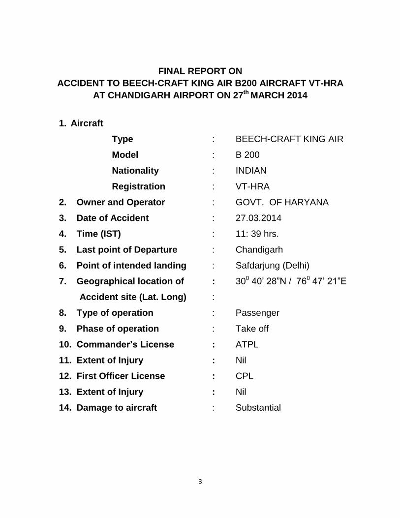
1. Aircraft
Type : BEECH-CRAFT KING AIR
Model : B 200
Nationality : INDIAN
Registration : VT-HRA
2. Owner and Operator : GOVT. OF HARYANA
3. Date of Accident : 27.03.2014
4. Time (IST) : 11: 39 hrs.
5. Last point of Departure : Chandigarh
6. Point of intended landing : Safdarjung (Delhi)
7. Geographical location of : 300 40‟ 28”N / 760 47‟ 21”E
Accident site (Lat. Long) :
8. Type of operation : Passenger
9. Phase of operation : Take off
10. Commander’s License : ATPL
11. Extent of Injury : Nil
12. First Officer License : CPL
13. Extent of Injury : Nil
14. Damage to aircraft : Substantial

4
I N D E X
SYNOPSIS 6
1.0 FACTUAL INFORMATION 7
1.1 History of the flight 7
1.2 Injuries to persons 8
1.3 Damage to aircraft 9
1.4 Other damage 10
1.5 Personnel information 10
1.5.1 Pilot – in – Command 10
1.5.2 Co-Pilot 10
1.6 Aircraft information 11
1.7 Meteorological information 16
1.8 Aids to navigation 16
1.9 Communications 17
1.10 Aerodrome information 17
1.11 Flight recorders 17
1.12 Wreckage and impact information 17
1.13 Medical and pathological Information 20
1.14 Fire 20
1.15 Survival aspects 20
1.16 Tests and research 20
1.17 Organizational and management information 20

5
1.18 Additional information: 21
1.19 Useful or effective investigation techniques 23
2.0 ANALYSIS 24
2.1 Serviceability of the aircraft 24
2.2 Crew Qualification 26
2.3 Weather 27
2.4 Circumstances leading to the accident 27
3.0 CONCLUSIONS 29
3.1 Findings 29
3.2 Probable cause of the Incident 30
4.0 SAFETY RECOMMENDATIONS 31

6
SYNOPSIS :
Beech Craft King Air B200 aircraft VT-HRA was involved in an accident at Chandigarh
airport on 27th March 2014. Within 3-4 seconds of getting airborne the aircraft impacted
the ground in left bank attitude. The initial impact was on pucca (tar road) and the left
wing took the impact loads with lower metallic surface rubbing and screeching on
ground.
The aircraft was substantially damaged. There was no fire barring burning of small
patch of grass due coming in contact with the hot surfaces and oil. There was no injury
to any of the occupants. The accident occurred in day light conditions.
Government of India vide notification no. AV.15018/12/2014-VE ordered the
investigation of the accident by a Committee of Inquiry. The intimation of the accident
was provided to ICAO, TSB Canada and NTSB USA as per the requirements of ICAO
Annexure 13.
The investigation of the accident was carried out by taking into account all the
evidences on record. The accident occurred due to stalling of left wing of the
aircraft at a very low height. The contributory factors were:
Crew was not able to effectively put off the yaw damp so as to release
the rudder stiffness as per the emergency checklist.
Checklist not being carried out by the crew members.
Not putting off the Rudder Boost.
Speeds call outs not made by co-pilot.
Not abandoning the take-off at lower speed (before V1).
Failure of CRM in the cockpit in case of emergency.
Early rotation and haste to take-off.
7
1. Factual Information 1.1 History of flight
On 25.03.2014, the operator received the travel programme for 27.3.2014, of
Hon‟ble Governor of Haryana from Chandigarh to Delhi. On 26.3.2014, the
operations department took the flight clearances and filed the passenger
manifest with the ATC and other concerned agencies.
The flight plan was filed by a CPL holder, who is working as flight dispatcher
with the Government of Haryana. The departure on 27.3.2014 was fixed at
1130 hrs. The cockpit crew reported at 1045 hrs for the flight. Pre flight
medical examination including the breath analyzer test was carried out at
1100 hrs. The breath analyzer test for both the cockpit crew members was
negative. Pre flight briefing among the crew members was carried out by
using the documents prepared by the flight dispatcher. The aircraft was taxied
under its own power from Haryana Government Hangar to bay no. D-2 in
front of ATC building. No abnormality was observed or reported on the aircraft
during this taxiing. The engines were shut down for passenger embarkation.
As per the passenger manifest, in addition to the pilot and co-pilot there were
8 passengers. The baggage on board was approx. 50 lbs. There was 2100
lbs. of fuel on board. After boarding of the passengers, the aircraft engines
were started at 1130 hrs. The aircraft was cleared for departure abeam „D‟
link. The aircraft was taxied out via taxiway „D‟. After ATC departure
clearance the aircraft was lined up for take-off. On clearance from ATC the
take off roll was initiated and all the parameters were found normal. As per
the pilot just before getting airborne some stiffness was found in rudder
control as is felt in yaw damper engagement. The aircraft then pulled slightly
to the left which as per the Commander was controllable. As per the pilot, the
rotation was initiated at 98 knots.
As per the DATCO the aircraft had lifted upto 10-15 feet AGL. The
Commander has stated that after lift-off, immediately the left rudder got
locked in forward position resulting in the aircraft yawing and rolling to left.
The pilots tried to control it with right bank but the aircraft could not be
controlled. Within 3-4 seconds of getting airborne the aircraft impacted the
ground in left bank attitude. The initial impact was on pucca (tar road) and the
wing has taken the first impact loads with lower surface metallic surface
rubbing and screeching on ground.

8
After the aircraft came to final halt, the co-pilot opened the door and
evacuation was carried out. There was no injury to any of the occupants. The
engine conditions lever could not be brought back as these were stuck. The
throttle and pitch levers were retarded. The fuel shut off valves were closed.
Battery and avionics were put off. Friction lock nuts were found loose.
As per the Commander, after ensuring safety of passengers he had gone to
cockpit to confirm that all switches were „off‟. At that time he has loosened the
friction lock nuts to bring back the condition lever and throttle lever. However
even after loosening the nut it was not possible to bring back these levers.
Fire fighting vehicles were activated by pressing crash bell and primary alarm.
Hand held RT set was used to announce the crash. RCFF vehicles
proceeded to the site via runway and reported all the 10 personnel are safe
and out of the disabled aircraft. Water and complementary agents (foam and
dry chemical powder) were used. After fire was extinguished, the Fire
Fighting vehicles reported back at crash bay except one CFT which was held
at crash site under instruction of COO.
The aircraft was substantially damaged. There was no fire barring burning of
small patch of grass due coming in contact with the hot surfaces and oil.
There was no injury to any of the occupants. The accident occurred in day
light conditions.
1.2 Injuries to persons
INJURIES CREW PASSENGERS OTHERS
FATAL Nil Nil Nil
SERIOUS Nil Nil Nil
NONE 2 8

9
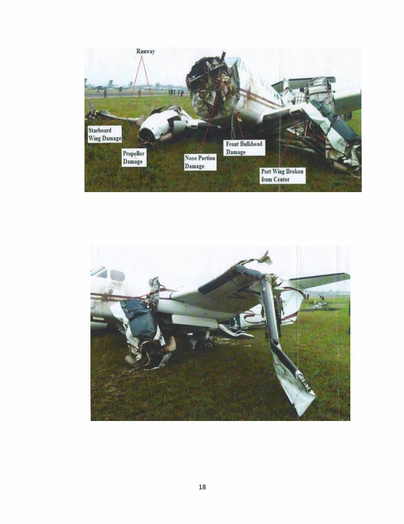
1.3 Damage to aircraft
The aircraft was substantially damaged particularly the wings, landing gear,
both the engines bottom surfaces. The major damages to the aircraft are as
follows:
On left hand side the out board wing section was damaged and ripped off at
6‟ outboard from the wing attachment point and again bent at around 13‟ from
the wing attachment point). Wing tip suffered substantial damage. Aileron was
found damaged and broken due to impact. LH Engine ripped off from the four
engine mounts with all pipelines broken from firewall. Friction lock nut was
found loose. Condition lever position was found toward low idle with control
cable intact. Power lever cable found broken from the eye end. LH Landing
gear found extended (11”) and locked. No visible damage on Landing gear.
Dorsal fin ripped off from the mounting and found with the Vertical stabilizer.
On right hand side dents were observed around the aft pressure bulkhead.
Outboard tip of Inboard flap and inboard tip of outboard flap were found
damaged. Wing leading edge section ripped off from the forward piano hinge.
Wing tip suffered extensive damage. RH MLG broke from structural mounting.
Lower drag brace found broken. RH Landing gear doors were found
completely damaged. RH Engine found ripped off from all the four mounting
points. Condition lever found at high idle and cable found bent and intact.
Power lever found at low power and cable found intact.
In the nose section, Nose landing gear broke from mounting. Nose section
completely dislodged from the fuselage. Radome found dislodged and
completely damaged. Inner cylinder of nose landing gear shock absorber
found dislodged of the landing gear along with nose wheel assembly. Shimmy
damper found broken from the piston. Nose landing gear Steering linkage
found completely damaged. Nose landing gear torque link separated from the
scissor linkage point.
LH engine Propeller assembly was found near the wingtip of RH Wing. One
blade of LH Propeller ripped off at around 17” from the root. Extensive
rubbing marks of all LH Propeller blade tips. All blades of LH Propeller found
bent and completely damaged. LH and RH Propeller Spinner assembly found
completely damaged. All blades of RH Propeller found rubbed at the tip and
completely damaged.

10
1.4 Other damage
Nil
1.5 Personnel information
1.5.1 Pilot – in – Command
Age : 58 years
License : ATPL
Date of Issue : 24.09.1992
Validity : Valid
Category : Multi Engine land
Endorsements as PIC Endorsement as PIC : B 737, B-200, Open rating
Date of Medical Examination : 11/03/2014
Med. Exam valid upto : 10/09/2014
FRTO License : Valid
Total flying experience : 9888:50 hrs.
Experience on type : 2165:40 hrs.
Experience as PIC on type : 1736:10 hrs.
Total flying experience during 90 days : 61:40 hrs.
Total flying experience during 30 days : 02:50 hrs.
Total flying experience during 07 Days : nil
Total flying experience during 24 Hours : nil
1.5.2 Co-Pilot
Age : 42 years
License : CPL
Validity : Valid
Date of Medical Examination : 05/03/2014

11
Med. Exam valid upto : 04/03/2015
FRTO License : Valid
Total flying experience : 2147:25 hrs.
Experience on type : 1383:05 hrs.
Experience as PIC on type : 398:15 hrs.
Total flying experience during 90 days : 55:30 hrs.
Total flying experience during 30 days : 2:50 hrs.
Total flying experience during 07 Days : 00 hrs
Total flying experience during 24 Hours : 00 hrs
1.6 Aircraft information
The aircraft was manufactured by M/s Raytheon Aircraft Company in 2005.
The aircraft is powered by 02 (two) PW PT6A-42 turboprop engines. These
engines have a Horsepower rating of 850 SHP with engine speed of 101.5%
N1 (38,100 RPM). The engines are fitted with Hartzell Inc Propellers model
No.HC-D4N-3A having 04 blades. The aircraft has a seating capacity of 10
persons including cockpit crew. The aircraft is certified for a single pilot
operation. There is only one door for normal entry/exit of the crew,
passengers and cargo. The aircraft has a total fuelling capacity of around
3636 lbs.
The aircraft was issued with Indian Certificate of Registration (C of R) no.
3295/2 in the name of the operator. Scrutiny of the Airframe and Engine log
books of the aircraft revealed that till the day of accident, the aircraft had done
2010.26 airframe hrs since new and 102.40 since the renewal of last C of A.
The engine had also logged 2010.26 hrs. since new. The last C of A was
done on 24.09.2013 and was valid till 28.07.2015. The aircraft was registered
under Normal category with subdivision as Passenger. The highest inspection
schedule on this aircraft is Phase IV (800 hrs) which was carried out on the
aircraft on 23.09.2013 at 1907.46 airframe hrs. The last inspection schedule
carried out was Phase I (200 hrs) and was carried out on the aircraft on
04.03.2014 at 2007.51 airframe hrs. The last flight operated by the aircraft
was on 14.03.2014 and the periodic ground run was carried out on
21.03.2014.

12
The aircraft was issued with Certificate of Release to Service on 27.03.2014
after daily inspection. There was no snag on the aircraft after renewal of C of
A and the last snag reported was related to LH engine bleed air annunciator
on 22.08.2013. There was no snag reported on primary flight controls or
engine system.
All the mandatory modifications/SBs were found to be complied with. On the
day of the accident the Daily Inspection was carried on the aircraft by an
approved AME. As per the defect register maintained by the operator no snag
or defect was reported on the aircraft after 22.08.2013. Prior to that also
there was no snag relating to the aircraft controls.
FLIGHT CONTROLS - CONTROL SURFACES
The airplane is equipped with conventional ailerons and rudder. It utilizes a T-
tail horizontal stabilizer and elevators, mounted at the extreme top of the
vertical stabilizer.
OPERATING MECHANISMS
The airplane is equipped with conventional dual controls for the pilot and
copilot. The ailerons and elevators are operated by conventional control
wheels interconnected by a bar. The rudder pedals are interconnected by
linkage below the floor. These systems are connected to the control surfaces
through push-rod and cable-and-bellcrank systems. Rudder, elevator, and
aileron trim are adjustable with controls mounted on the center pedestal. A
position indicator for each of the trim tabs is integrated with its respective
control.
MANUAL ELEVATOR TRIM
Manual control of the elevator trim is accomplished with a trim control wheel
located on the left side of the pedestal. It is a conventional trim wheel which is
rolled forward for nose-down trim, and aft for nose-up trim.
ELECTRIC ELEVATOR TRIM
The electric elevator-trim system (installed in conjunction with the autopilot
system) is controlled by a dual-element thumb switch on each control wheel,
a trim-disconnect switch on each control wheel, and a PITCH TRIM circuit
breaker in the FLIGHT group on the right side circuit breaker panel. Both
elements of either dual- element thumb switch must be simultaneously moved
forward to achieve nose-down trim, aft for nose-up trim; when released, they
return to the center (OFF) position. Any activation of the trim system by the

13
copilot's thumb switch can be overridden by the pilot's thumb switch. No one
switch element activates the system; only the simultaneous movement of a
pair of switch elements in the same direction activates the system.
A bi-level, push-button, momentary-on, trim-disconnect switch is located
inboard of the dual-element thumb switch on the outboard grip of each control
wheel. The electric elevator-trim system can be disconnected by depressing
either of these switches. Depressing either trim-disconnect switch to the first
of the two levels disconnects the autopilot and yaw damp systems;
depressing the switch to the second level disconnects the electric elevator-
trim system. The manual-trim control wheel can be used to change the trim
anytime the autopilot is off, whether or not the electric trim system is in the
operative mode.
RUDDER BOOST
A rudder boost system is provided to aid the pilot in maintaining directional
control in the event of an engine failure or a large variation of power between
the engines. Incorporated into the rudder cable system are two pneumatic
rudder-boosting servos that actuate the cables to provide rudder pressure to
help compensate for asymmetrical thrust.
During operation, a differential pressure valve accepts bleed air pressure from
each engine. When the pressure varies between the bleed air systems, the
shuttle in the differential pressure valve moves toward the low pressure side.
As the pressure difference reaches a preset tolerance, a switch on the low
pressure side closes, activating the rudder boost system. The system is
designed only to help compensate for asymmetrical thrust. Appropriate
trimming is to be accomplished by the pilot. Moving either or both of the bleed
air valve switches on the copilot's subpanel to the “INSTR & ENVIR OFF”
position will disengage the rudder boost system.
The system is controlled by a toggle switch, placarded RUDDER BOOST -
OFF, located on the pedestal below the rudder trim wheel. The switch is to be
turned ON before flight.
A preflight check of the system can be performed during the runup by
retarding the power on one engine to idle and advancing power on the op-
posite engine until the power difference between the engines is great enough
to close the switch that activates the rudder boost system. Movement of the
appropriate rudder pedal (left engine idling, right rudder pedal moves forward)
will be noted when the switch closes, indicating the system is functioning
14
properly for low engine power on that side. Repeat the check with opposite
power settings to check for movement of the opposite rudder pedal.
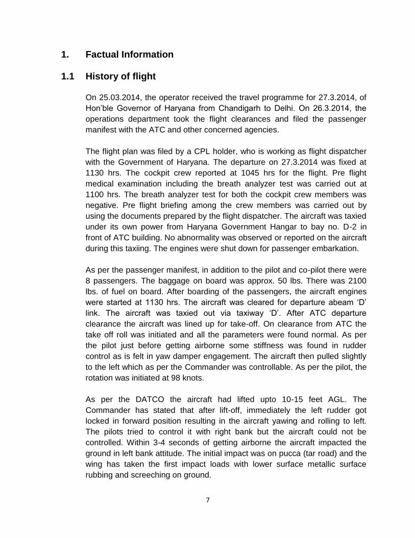
YAW DAMP
A yaw damp system is part of the autopilot and is provided to aid the pilot in
maintaining directional control, and to increase ride comfort. The system may
be used at any altitude, and is required for flight above 17,000 feet. It should
be deactivated for takeoff and landing.
The yaw damper is automatically engaged anytime the autopilot is engaged,
except when rudder boost is activated. To disengage the yaw damper, slide
the YD/ AP DISC switch down on the FGP panel, press the YD push-button,
or press the DISC TRIM/AP YD switch on the pilot's or copilot's control wheel
to the first detent.
ANNUNCIATOR SYSTEM
The annunciator system consists of a warning annunciator panel (red)
centrally located in the glare shield, and a caution/advisory annunciator panel
(caution - amber; advisory - green) located on the center subpanel. Two red
MASTER WARNING flashers located in the glare shield (one in front of the
pilot and one in front of the copilot) are a part of the system, as are two amber
MASTER CAUTION flashers (located just inboard of the MASTER WARNING
flashers), and a PRESS TO TEST button located immediately to the right of
the warning annunciator panel.
The annunciators are of the word-readout type. Whenever a condition
monitored by the annunciator system occurs, a signal is generated and the
appropriate annunciator is illuminated.
If the fault requires the immediate attention and reaction of the pilot, the
appropriate red warning annunciator in the warning annunciator panel
illuminates and both MASTER WARNING flashers begin flashing. Any
illuminated lens in the warning annunciator panel will remain illuminated until
the fault is corrected. However, the MASTER WARNING flashers can be
extinguished by depressing the face of either MASTER WARNING flasher,
even if the fault is not corrected. In such a case, the MASTER WARNING
flashers will again be activated if an additional warning annunciator
illuminates. When a warning fault is corrected, the affected warning
annunciator will extinguish, but the MASTER WARNING flashers will continue
flashing until one of them is pressed.

15
FLIGHT CONTROL ASSIST SYSTEMS - RUDDER BOOST SYSTEM
When the airplane is not equipped with an autopilot, the standard rudder
installation provides for rudder boosting and yaw damping functions.
Otherwise, these functions are provided by the autopilot. The systems
components are two pneumatic rudder servos, one pressure regulator and
two vented solenoid valves, all located aft of Fuselage Station (FS) 368.00,
an inline air filter mounted on the aft side of the aft pressure bulkhead and a
differential pressure switch located near the bleed air de-ice manifold. Each
servo is attached to the primary rudder cable by a cable and clamp. The
servo can be disconnected by removing one nut and on removing the servo
cable and clamp.
Each system is energized by a two position toggle switch on the pedestal
placarded “RUDDER BOOST ON OFF”. The systems are protected by a 5
amp circuit breaker on the right hand circuit breaker panel. The pressure
regulator is adjusted to 15 + 0.5 psi to boost the rudder against a failed
engine. When the air flow from either engine is reduced to the point that it
places a differential pressure across the pressure differential switch, it
actuates the appropriate solenoid valve allowing pressure from the de-ice
manifold to actuate the rudder servo.
FRICTION LOCK OF ENGINE CONTROLS
The Engine controls of SKA B200 are governed by two power and condition
levers of each engine, two prop lever for each propellers. All the controls are
equipped with friction pads controlled by a knob on the power quadrant of
pedestal below the knobs to control the friction on each control and its
movability. The friction locks are provided to prevent control creep back due
to cockpit vibration, springiness of control cables etc during all the phases of
flight.
Four friction locks are located, one for each power lever is equipped with a
friction brake, and one friction brake is available for both prop levers and
condition levers.
Clockwise movement of the knob increase the friction on the controls and
levers progressively become more resistant to movement.
As per the checklist for Before takeoff (run up) of POH Pg 4-20, engine
controls friction locks are required to be SET.
16
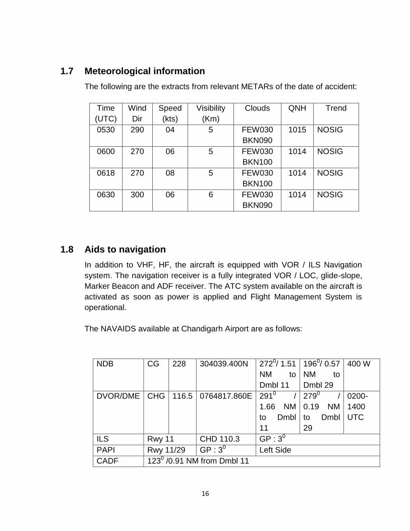
1.7 Meteorological information
The following are the extracts from relevant METARs of the date of accident:
Time
(UTC)
Wind
Dir
Speed
(kts)
Visibility
(Km)
Clouds QNH Trend
0530 290 04 5 FEW030
BKN090
1015 NOSIG
0600 270 06 5 FEW030
BKN100
1014 NOSIG
0618 270 08 5 FEW030
BKN100
1014 NOSIG
0630 300 06 6 FEW030
BKN090
1014 NOSIG
1.8 Aids to navigation
In addition to VHF, HF, the aircraft is equipped with VOR / ILS Navigation
system. The navigation receiver is a fully integrated VOR / LOC, glide-slope,
Marker Beacon and ADF receiver. The ATC system available on the aircraft is
activated as soon as power is applied and Flight Management System is
operational.
The NAVAIDS available at Chandigarh Airport are as follows:
NDB CG 228 304039.400N 2720/ 1.51
NM to
Dmbl 11
1960/ 0.57
NM to
Dmbl 29
400 W
DVOR/DME CHG 116.5 0764817.860E 2910 /
1.66 NM
to Dmbl
11
2790 /
0.19 NM
to Dmbl
29
0200-
1400
UTC
ILS Rwy 11 CHD 110.3 GP : 30
PAPI Rwy 11/29 GP : 30 Left Side
CADF 1230 /0.91 NM from Dmbl 11

17
1.9 Communications
There was two way communications between the aircraft and ATC.
1.10 Aerodrome information
Chandigarh Aerodrome is a Defence airfield with civil enclave owned by
Airports Authority of India. There is only one runway (11/29) of length 9000 ft
and width 150 ft. First 900 ft on either side of the runway is of concrete and
the rest of portion is bitumen. ILS/DME, VOR/DME is available for runway 11.
The communication frequency for tower and approach is 118.3 & 118.6
respectively.
1.11 Flight recorders
The aircraft was equipped with Fairchild CVR FA 2100 with Part No. 2100 –
1020-00 and Sl. No. 000333366. The CVR was replayed at the facilities of
Aircraft Engineering Directorate (AED) of DGCA. Neither there was any
requirement for fitment of FDR nor was any fitted on the aircraft.
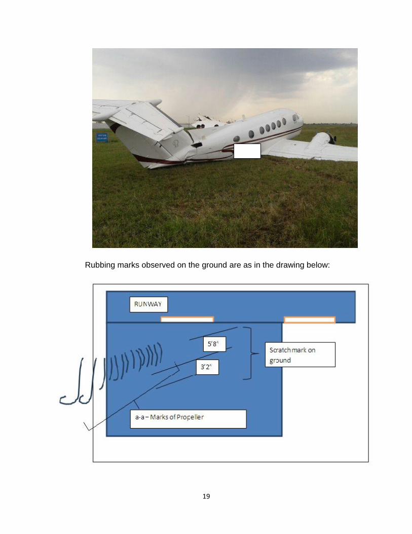
1.12 Wreckage and impact information
Within 3-4 seconds of getting airborne the aircraft impacted ground in left
bank attitude. The initial impact was on pucca (tar road) and the left wing has
taken the first impact loads with lower surface metallic surface rubbing on
ground.
On the ground, there were marks of the propeller. The propeller blades of the
left engine had made cut marks on the ground and then skidding of the
aircraft. On the way both the propeller hub assemblies have got detached
from the main structure. The nose section also got separated from the aircraft
and was lying at a distance of 30‟ from the final position of aircraft.
18
19
Rubbing marks observed on the ground are as in the drawing below:
20
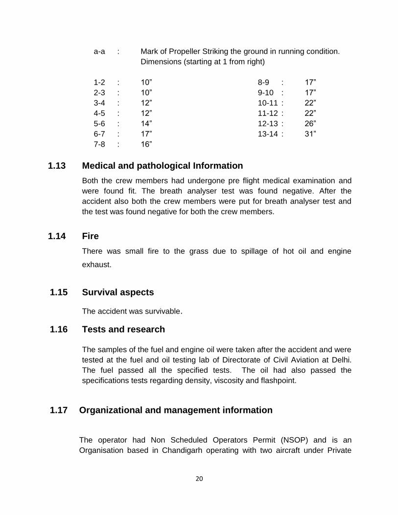
a-a : Mark of Propeller Striking the ground in running condition.
Dimensions (starting at 1 from right)
1-2 : 10” 8-9 : 17”
2-3 : 10” 9-10 : 17”
3-4 : 12” 10-11 : 22”
4-5 : 12” 11-12 : 22”
5-6 : 14” 12-13 : 26”
6-7 : 17” 13-14 : 31”
7-8 : 16”
1.13 Medical and pathological Information
Both the crew members had undergone pre flight medical examination and
were found fit. The breath analyser test was found negative. After the
accident also both the crew members were put for breath analyser test and
the test was found negative for both the crew members.
1.14 Fire
There was small fire to the grass due to spillage of hot oil and engine
exhaust.
1.15 Survival aspects
The accident was survivable.
1.16 Tests and research
The samples of the fuel and engine oil were taken after the accident and were
tested at the fuel and oil testing lab of Directorate of Civil Aviation at Delhi.
The fuel passed all the specified tests. The oil had also passed the
specifications tests regarding density, viscosity and flashpoint.
1.17 Organizational and management information
The operator had Non Scheduled Operators Permit (NSOP) and is an
Organisation based in Chandigarh operating with two aircraft under Private
21
Operations for the use of State Government VIPs. The organisation was
structured under the management of the Accountable Manager.
The operating permit no. 03/2011 was valid till 22.12.2015. The Organisation
had approved CAME. The continuing airworthiness of the aircraft was
managed by CAMO approved organisation at New Delhi and Chandigarh. The
continuing airworthiness management functions were subcontracted to third
party. The maintenance was being carried out by another third party within the
requirements of CAR on the subject. The operations manual available with the
operator defines the duties and responsibilities of the cockpit member. In
addition to other responsibilities the pilot in command is responsible for
Use of the check list for every phase of flight.
Ensuring that no hazardous flight maneuver is executed during any
phase of the flight.
Affording every opportunity to the Co- Pilot to prepare himself for the
position of Pilot – in- command and explaining methods and procedures
being adopted.
The duties of co-pilot include
Render all material assistance to the Pilot –in-command
Shall carry out all duties pertaining to the operation of the flights as
directed by the Pilot-in-command.
Read out of the check list at the appropriate times and ensure that
same is being complied with.
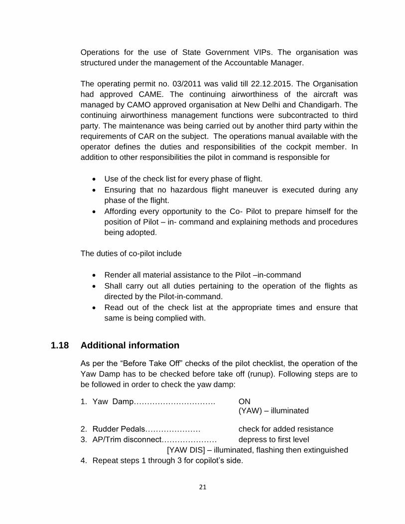
1.18 Additional information
As per the “Before Take Off” checks of the pilot checklist, the operation of the
Yaw Damp has to be checked before take off (runup). Following steps are to
be followed in order to check the yaw damp:
1. Yaw Damp…………………………. ON (YAW) – illuminated
2. Rudder Pedals………………… check for added resistance
3. AP/Trim disconnect………………… depress to first level
[YAW DIS] – illuminated, flashing then extinguished
4. Repeat steps 1 through 3 for copilot‟s side.

22
Similarly primary governor, over-speed governor and rudder boost is to be
checked as follows:
1. Rudder Boost ON
2. Prop Governor Test Switch Hold to test
3. Power levers (individually) Increase until prop is stabilized at 1800 to 1910 RPM
4. Prop Lever Retard to detent, then full forward
(to check primary governor)
5. Power Lever Continue to increase until rudder movement is noted (Observe ITT and Torque limits)
6. Power Lever Idle
7. Repeat steps 3 thru 6 on opposite engine
8. Prop Governor Test Switch Release
Further, as per the Section 3 of the “Emergency Procedures” of the Pilot
Operating Handbook of the aircraft, the rudder boost operation without a large
variation of power between the engines indicates a failure of the system. In
such a situation
1. Directional Control …………. ………..maintain using rudder pedals
2. Rudder Boost …………………………………………………OFF
As per para 6.15 of CAR - Section 3, Series C, Part X
“When operating VIP flights with fixed wing aircraft, the pilot-in-
command shall possess CPL or ATPL with at least 3000 hours including
2000 hours as PIC, 50 hours as PIC on type of aircraft to be flown and 50
hours of night flying experience. In addition, the pilot should have a
minimum of 30 hours as PIC experience in the last 6 months including five
hours on type in the last thirty days of the intended flight. In case 30 hrs.
recency during the last 6 months is not met with, then in last 30 days, a
satisfactory skill test (as required for licence renewal) shall be carried out
followed by 5 hrs. of PIC experience.”

23
Further as per the Note 2 to para 6.17 of the CAR, VIP flight means a flight
having among its passengers any dignitaries (as per the list given there)
which include Governors of State.
1.19 Useful or effective investigation techniques
Nil

24
2. ANALYSIS
2.1 Serviceability of the aircraft
The aircraft was having valid Certificate of Airworthiness, Certificate of
Registration and Flight Release. On the day of accident the AME carried out
the inspection. There was no snag and the aircraft was released for operation.
No item was released under MEL. The pilot had also accepted the aircraft and
the aircraft was moved under its own power from the Government Hangar for
embarkation of passengers from the bay indicating that all the controls
including rudder were operating in correct sense.
The engines were shut down. The crew has not reported any snag on the
aircraft systems or engines. No difficulty was reported by the crew regarding
operation of flight controls. The aircraft was again started and taken to runway
under its own power.
The crew members have reported that engines were generating full power.
The rudder boost was also serviceable before take-off. Till the beginning of
take off roll, the controls were functioning satisfactorily. The Commander had
reported that just before getting airborne some stiffness was found in rudder
control as is felt in yaw damper engagement. As per the co-pilot soon after
take-off roll the aircraft had started going to the left and continued to go to left
as the speed increased. He also mentioned that the aircraft had got airborne
from very close to the left edge of the runway.
As per the “Before Take Off” checks of the pilot checklist, the operation of the
Yaw Damp has to be checked before takeoff (runup) for both the Captain and
Co-pilot side. By putting yaw damp „ON‟, the rudder pedals are checked to see
for added resistance in operation.
As per Section 3 of the “Emergency Procedures” of the Pilot Operating
Handbook of the aircraft, the rudder boost operation without a large variation
of power between the engines indicates a failure of the system. In such a
situation the directional control is maintained by using rudder pedals after
putting the rudder Boost to „OFF‟.
The CVR was removed and tape transcript of the relevant portion was
prepared. It was observed that no check list was carried out by the flying crew.
This was agreed by the co-pilot also.
25
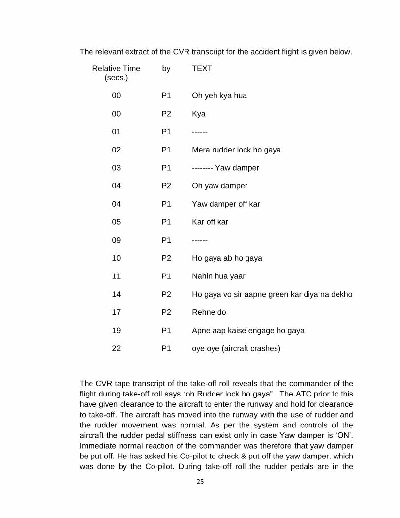
The relevant extract of the CVR transcript for the accident flight is given below.
Relative Time (secs.)
by TEXT
00 P1 Oh yeh kya hua
00 P2 Kya
01 P1 ------
02 P1 Mera rudder lock ho gaya
03 P1 -------- Yaw damper
04 P2 Oh yaw damper
04 P1 Yaw damper off kar
05 P1 Kar off kar
09 P1 ------
10 P2 Ho gaya ab ho gaya
11 P1 Nahin hua yaar
14 P2 Ho gaya vo sir aapne green kar diya na dekho
17 P2 Rehne do
19 P1 Apne aap kaise engage ho gaya
22 P1 oye oye (aircraft crashes)
The CVR tape transcript of the take-off roll reveals that the commander of the
flight during take-off roll says “oh Rudder lock ho gaya”. The ATC prior to this
have given clearance to the aircraft to enter the runway and hold for clearance
to take-off. The aircraft has moved into the runway with the use of rudder and
the rudder movement was normal. As per the system and controls of the
aircraft the rudder pedal stiffness can exist only in case Yaw damper is „ON‟.
Immediate normal reaction of the commander was therefore that yaw damper
be put off. He has asked his Co-pilot to check & put off the yaw damper, which
was done by the Co-pilot. During take-off roll the rudder pedals are in the

26
neutral position and the need of using rudder pedal arises only in case the
aircraft is not going straight. The emergency of Rudder pedal stiffness could
have been handled by taking corrective actions as mentioned in the report or
just by rejecting takeoff.
From the schematic of the control system, there was no reason that why the
yaw damp lever should go to „ON‟ during takeoff roll assuming that it has not
been put „ON‟ inadvertently by the crew. The matter was taken up with the
manufacture of the control system to find out if any information can be
retrieved from the Data Concentrator Unit or Flight Guidance Computer. These
units as such do not have any memory. The Manufacturer advised that
Maintenance Diagnostic Computer may be sent first to check if any data is
there. The matter was deliberated and it was opined that no useful information
can be retrieved from the units. It was advised to the Committee that as it is
not sure that we can get some relevant information and the other evidences on
record are capable to stand alone, the Committee may go ahead with the
investigation with the existing evidences.
Rudder Control Cable was checked in the cabin, under the floor board for any
defect, damage or unusual observations. Inspection was found satisfactory.
Rudder was commanded by Rudder Pedal and responding as desired
confirming the cable continuity. Rudder Boost Differential Pressure Switch was
checked for current status and found “on ground” with “engine not running”.
The same was also found working satisfactorily during operational check.
A118 (K4) Relay was checked for status on ground and found “on ground” and
responding to Bleed Air Switches.
Autopilot Disconnect Switch on Cockpit Control Column (both Pilot and
Copilot) was checked for serviceability and no abnormality was observed.
From the foregoing, it can be safely concluded that the aircraft was fully
serviceable prior to take-off and the aircraft serviceability has not contributed
to the cause of accident.
2.2 Crew qualification
Both the crew members were qualified to undertake the flight. They had valid
licences with appropriate endorsements. They had valid Medical certificates
for carrying out flying. Pre Flight Medical checks were also carried out prior to
flight and after the accident on both of them. The Breath analyser test was
negative for both of them.
27
Honorable Governor of State is VIP as per Note 2 to para 6.17 of the CAR -
Section 3, Series C, Part X. The CAR requires that when operating VIP flights
with fixed wing aircraft, the pilot-in-command shall possess in addition to
other qualifications and experience, five hours of PIC experience in the last
thirty days of the intended flight. The Commander was not having 5 hours of
PIC experience in the last 30 days.
2.3 Weather
The sky was clear with few broken clouds at higher altitudes. The visibility
was 5 kms. without any significant changes anticipated. The visibility trend
was of improvement. The visibility and other weather conditions were
satisfactory for the conduct of flight and have not contributed to the accident.
2.4 Circumstances leading to the Accident
1. The Commander of the flight has stated that the yaw damper was not
engaged before the start of take-off roll and the Check-list was carried out
prior to start, after-start and before take-off. He has also said that sterile
cockpit environment was maintained during the flight. Whereas the co-pilot
stated that for positioning the aircraft at Bay D2 from the hangar he has
carried out the check-list but for the flight, it was not carried out. The CVR
was replayed which indicated that contrary to the statement of both the crew
members, no checklist was carried out at all. The CVR contained the
recording of last phase of earlier flight from Chandigarh to Delhi and full flight
from Delhi to Chandigarh. It was observed that no checklist has been carried
out during these flights.
2. As per the commander only after the speed of 80-85 knots was attained, it
pulled slightly to the left which was corrected by the help of rudders. After
which, a slight stiffness in the rudder was observed as in case of yaw-damper
engagement which when asked to the co-pilot was confirmed and observed to
be „OFF‟. This stiffness was only for 2-3 seconds and before the aircraft took-
off.
Whereas the co-pilot stated that soon after the take-off roll, the aircraft started
going to the left. As the speed increased, the aircraft continued to move to the
left. During lift-off, the aircraft was on the runway but towards the left of the
centre line. The Co-pilot was shown the video of the flight from take-off roll
onwards and the aircraft was found going to left and took off from close to the

28
left edge of the runway. So during initiation of take-off roll itself, the aircraft
had started going to left.
3. The crew have stated that they have not heard any stall warning. CVR was
played and the Co-pilot identified the stall warning.
4. As per the crew, both the engines were generating full-power. The power-
lever(s) were guarded by the co-pilot and speed & power checked before
rotation. The take-off weight was 12315 Lbs and unstuck speed of 99 knots
with Flaps „UP‟. The stalling speed of aircraft in take-off configuration with the
weight of 12315 lbs. and flaps UP is within 78-80 knots. As per the co-pilot,
just after start of the take-off roll (after gaining speed of 40 knots) aircraft
started going to the left.
5. As per the commander there was no identifiable emergency to warrant and
abort take-off nor was the aircraft uncontrollable. ADF, VOR, ILS, DME, FMS
and GPS were functional. Whereas the co-pilot stated that Capt. repeatedly
kept saying that the aircraft is getting out of control and he is unable to
understand why aircraft is behaving like that. At that time, the co-pilot gave a
reject take off call (rehne do). As per the co-pilot, the commander unstuck
rapidly, probably, he might have thought that by taking-off, he will be in
position to control the problem.
6. As per the system and controls of the aircraft the rudder pedal stiffness can
exist only in case Yaw damper is „ON‟. Immediate normal reaction of the
commander was therefore that yaw damper be put off. The yaw damp can be
put off from the toggle switch available on the Front or by pressing the switch
available on the control stick to first level. In addition it can also be put off by
Yaw damper/auto pilot disconnect switch. From the CVR transcript
(conversation between the crew) it appears that the commander has probably
pressed the switch available on the control stick to put the yaw damper off
and simultaneously told the co-pilot to put the yaw damp off. The co-pilot has
pressed the toggle switch available on the front. During takeoff roll, the co-
pilot had meekly told the Commander to reject take off (rehne do). At this
crucial moment of take-off roll, there was confusion in the cockpit and there
was failure of CRM.
7. The aircraft had rotated and lifted off almost from the left edge of the runway
and in little left bank attitude. In view of the emergent situation in the cockpit,

29
the Commander probably carried out rotation at a lower speed than VR. The
aircraft thereby stalled at a very low height and crashed.
In the hind sight, it is felt that the accident could have been avoided had the
crew
Put off the rudder boost switch.
Avoided simultaneous action of putting off the yaw damp by the
commander and co-pilot. Or
Rejecting the take-off.
3. CONCLUSIONS:
3.1 Findings:
1. The aircraft was having valid certificate of Registration and Certificate of
Airworthiness.
2. The Aircraft was issued Certificate of Release after carrying out daily
inspection on the day of accident and there was no snag reported.
3. All the mandatory modifications were complied with and there was no
deferred maintenance item or released under MEL.
4. No snag or defect was reported on the aircraft after 22.08.2013. prior to
that also, there was no snag relating to aircraft controls.
5. Both PIC and the Co-pilot were having valid licenses with appropriate
endorsements of Beechcraft King Air B-200.
6. PIC was not having 5 hrs. of PIC experience in the preceding 30 days.
7. Both the crew members held valid medical certificates as per the
requirement.
8. The crew had undergone pre-flight medical examination and nothing
abnormal was observed. The Breath Analyzer (BA) Test was negative.
Post-flight BA Test was also carried out and was negative.
9. On the day of accident, pre-flight briefing among the crew members was
carried out by using the documents prepared by a CPL holder (working as
Flight Dispatcher).
30
10. The aircraft was parked in Haryana Government Hangar and was taxied
from there under its own power to Bay No. D-2 in front of ATC Building.
No abnormality was reported by the crew on the aircraft.
11. After boarding of the passengers, the aircraft was taxied out via Taxiway D
and lined up for take-off.
12. No check-list was carried out by the crew for the flight. The conversation
before take-off roll between the crew members was not relevant to the
flight.
13. The Pilot has not reported any abnormality of aircraft parameters.
14. During the take-off roll, the pilot observed stiffness in the rudder control
and the aircraft pulled slightly to the left.
15. On observing that the yaw damp was ON, both the crew members tried to
put off the yaw damp & in the process yaw damp first got off and then on.
16. There was failure of CRM and the emergency of stiff rudder was not
handled as per the checklist.
17. The crew failed to reject the takeoff.
3.2 Probable cause of the accident
The accident occurred due to stalling of left wing of the aircraft at a very low
height. The contributory factors were:
Failure on the part of the crew to effectively put off the yaw damp so as
to release the rudder stiffness as per the emergency checklist.
Checklist not being carried out by the crew members.
Not putting off the Rudder Boost.
Speeds call outs not made by co-pilot.
Not abandoning the take-off at lower speed (before V1).
Failure of CRM in the cockpit in case of emergency.
Early rotation and haste to take-off.

31