Embed Size (px)
Citation preview

4/30/2015
1
New Tools in Aircraft Accident Reconstruction to Assist the Insurer
Steven L. “Steve” MorrisSenior Managing Consultant andManager of Colorado OperationsEngineering Systems Inc (ESI)
Overview
• ESI has reconstructed aircraft accidents since the company was founded in 1987
• Since then, we have participated in numerous aviation accident investigations both in and outside the U.S.
• Tape measures and cameras were essential accident reconstruction tools in 1987 and they are still very important tools today
• However, new powerful tools are now available and more are arriving every day
Overview
• X‐ray Computed Tomography (CT) of Parts
• Laser Scanning
• LiDAR
• New Aircraft Simulation Capabilities
4/30/2015
2
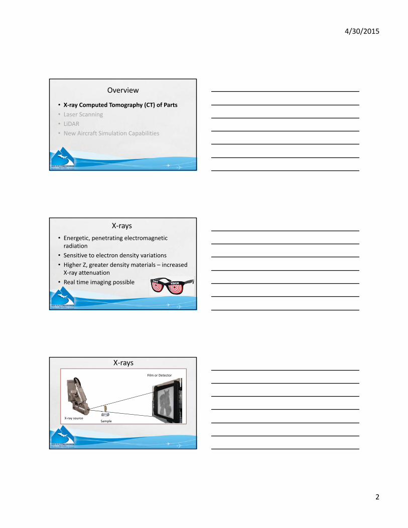
Overview
• X‐ray Computed Tomography (CT) of Parts
• Laser Scanning
• LiDAR
• New Aircraft Simulation Capabilities
X‐rays
• Energetic, penetrating electromagnetic radiation
• Sensitive to electron density variations
• Higher Z, greater density materials – increased X‐ray attenuation
• Real time imaging possible
X‐rays
X‐ray source
Film or Detector
Sample
4/30/2015
3
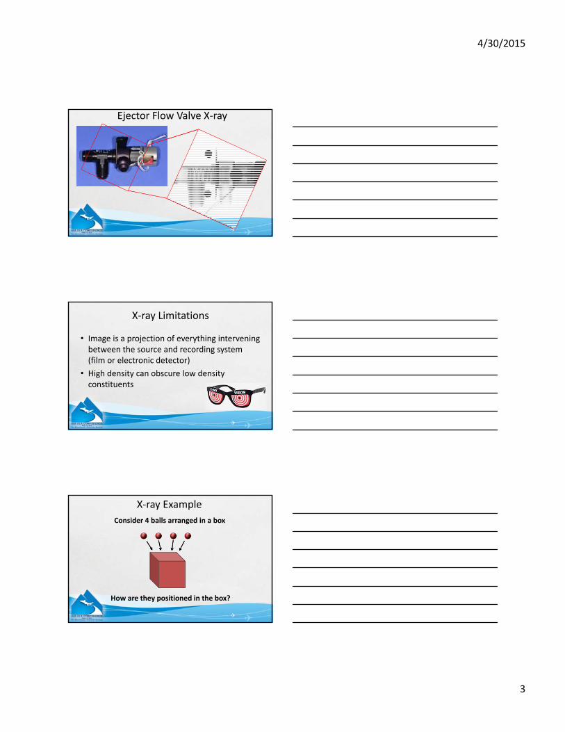
Ejector Flow Valve X‐ray
X‐ray Limitations
• Image is a projection of everything intervening between the source and recording system (film or electronic detector)
• High density can obscure low density constituents
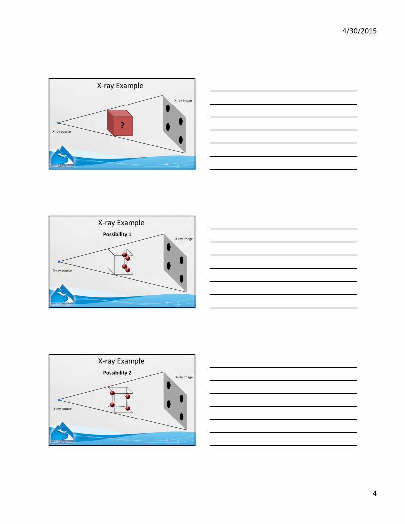
X‐ray Example
Consider 4 balls arranged in a box
How are they positioned in the box?
4/30/2015
4
X‐ray Example
?X‐ray source
X‐ray image
X‐ray Example
X‐ray source
X‐ray imagePossibility 1
X‐ray Example
X‐ray source
X‐ray imagePossibility 2
4/30/2015
5
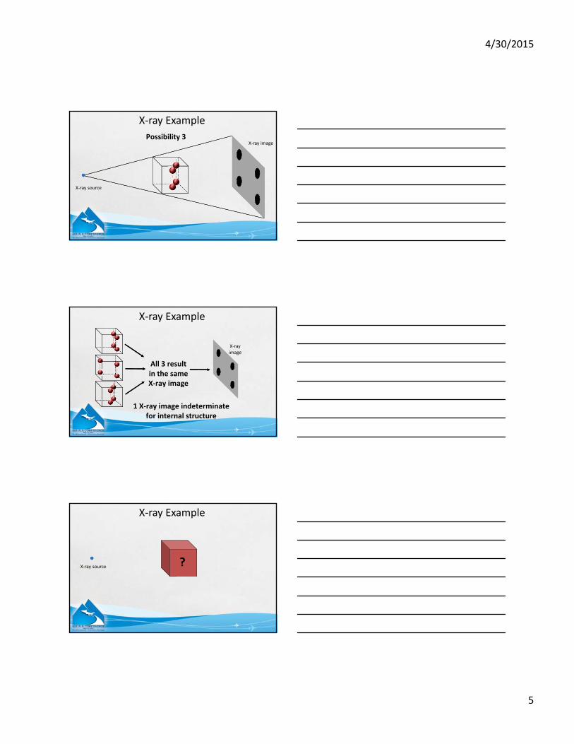
X‐ray Example
X‐ray source
X‐ray imagePossibility 3
X‐ray image
All 3 result in the same X‐ray image
1 X‐ray image indeterminate for internal structure
X‐ray Example
X‐ray Example
?X‐ray source
4/30/2015
6
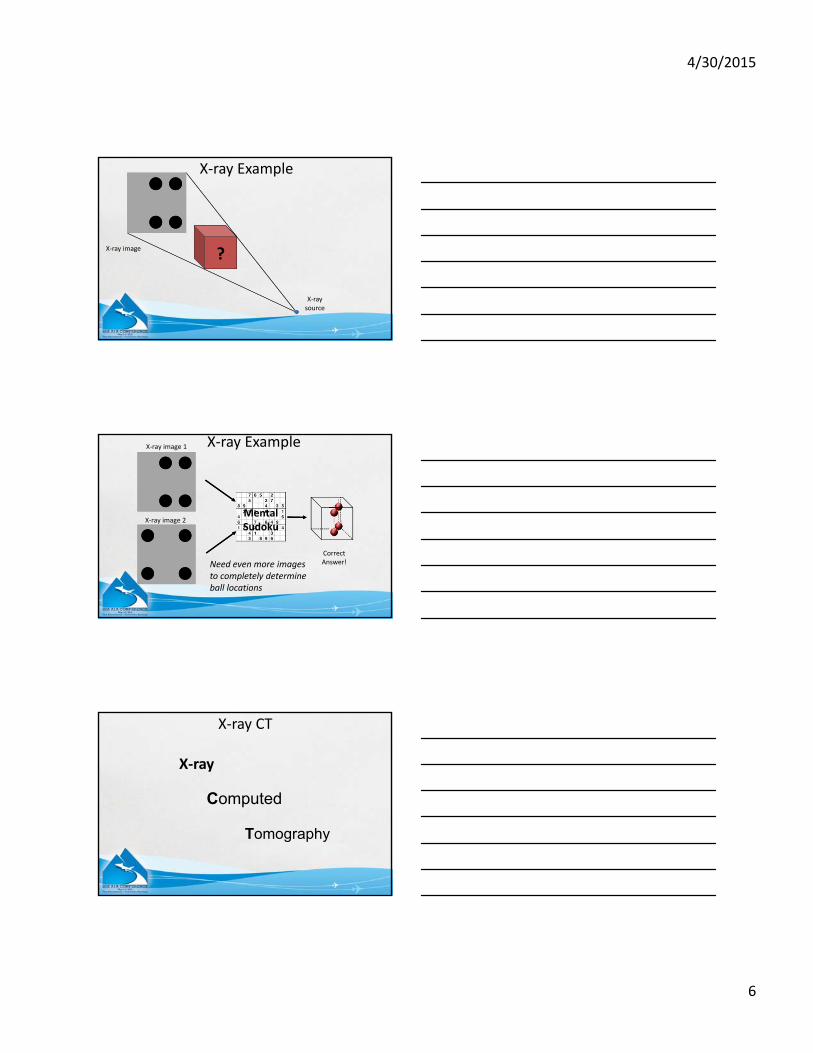
X‐ray Example
?
X‐ray source
X‐ray image
Correct Answer!
X‐ray image 1
X‐ray image 2MentalSudoku
X‐ray Example
Need even more imagesto completely determine ball locations
X‐ray CT
X‐ray
Computed
Tomography
4/30/2015
7
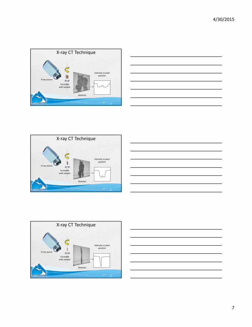
Intensity vs pixel position
Detector
Turntablewith sample
X‐ray source
X‐ray CT Technique
X‐ray CT Technique
Intensity vs pixel position
Detector
Turntablewith sample
X‐ray source
X‐ray CT Technique
Intensity vs pixel position
Detector
Turntablewith sample
X‐ray source
4/30/2015
8
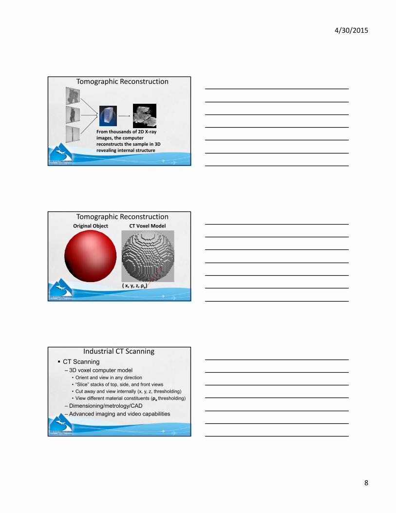
From thousands of 2D X‐ray images, the computer reconstructs the sample in 3D revealing internal structure
Tomographic Reconstruction
Original Object CT Voxel Model
( x, y, z, ρe)
Tomographic Reconstruction
CT Scanning– 3D voxel computer model
• Orient and view in any direction
• “Slice” stacks of top, side, and front views
• Cut away and view internally (x, y, z, thresholding)
• View different material constituents (ρe thresholding)
– Dimensioning/metrology/CAD
– Advanced imaging and video capabilities
Industrial CT Scanning
4/30/2015
9
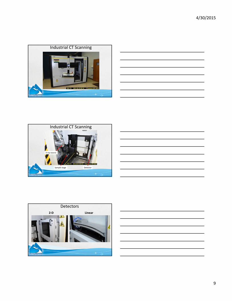
Industrial CT Scanning
X‐ray source
Sample stage Detector
Industrial CT Scanning
2‐D Linear
Detectors
4/30/2015
10
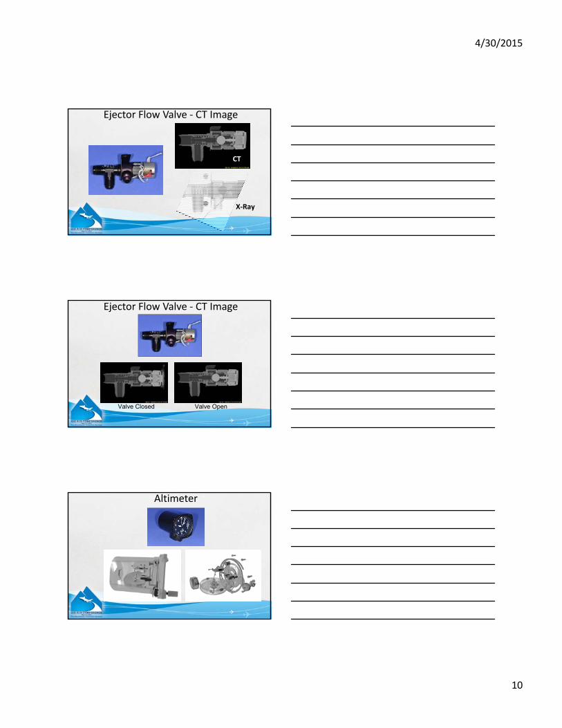
X‐Ray
CT
Ejector Flow Valve ‐ CT Image
Ejector Flow Valve ‐ CT Image
Valve Closed Valve Open
Altimeter
4/30/2015
11
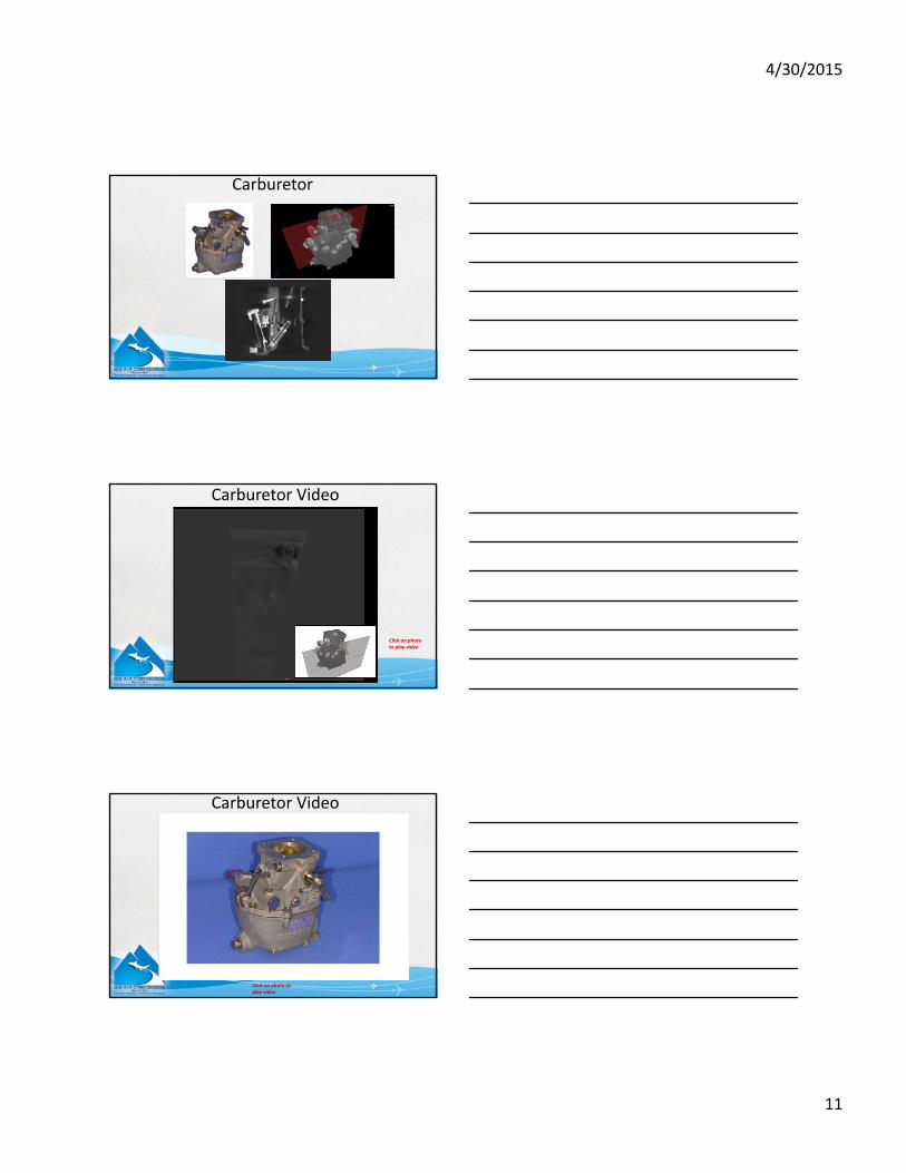
Carburetor
Click on photo to play video
Carburetor Video
Click on photo to play video
Carburetor Video
4/30/2015
12
Project Example
Pitch Servo
Pitch Servo
Pitch Servo
Pitch Servo
4/30/2015
13
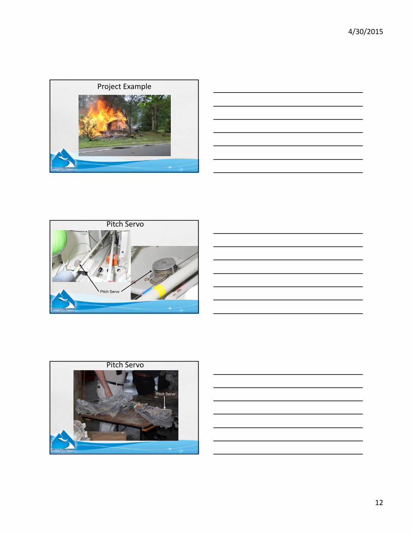
Pitch Servo
Capstan Gear
Pinion Gear
Capstan
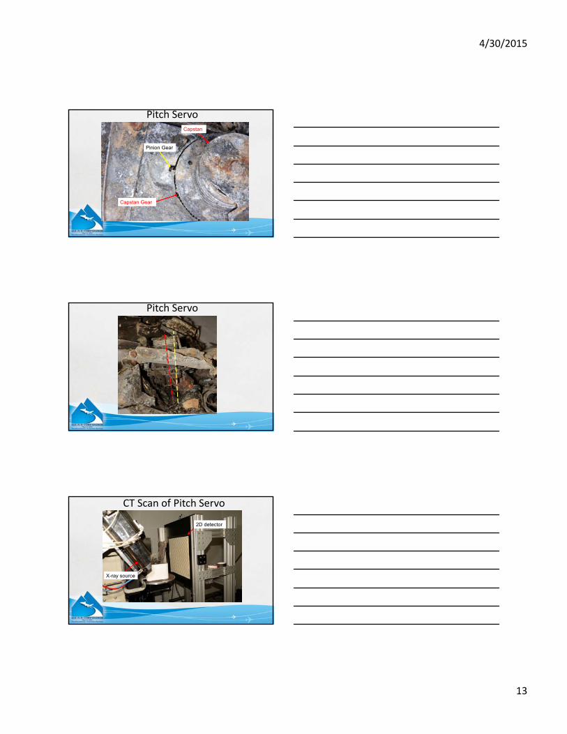
Pitch Servo
X-ray source
2D detector
CT Scan of Pitch Servo
4/30/2015
14
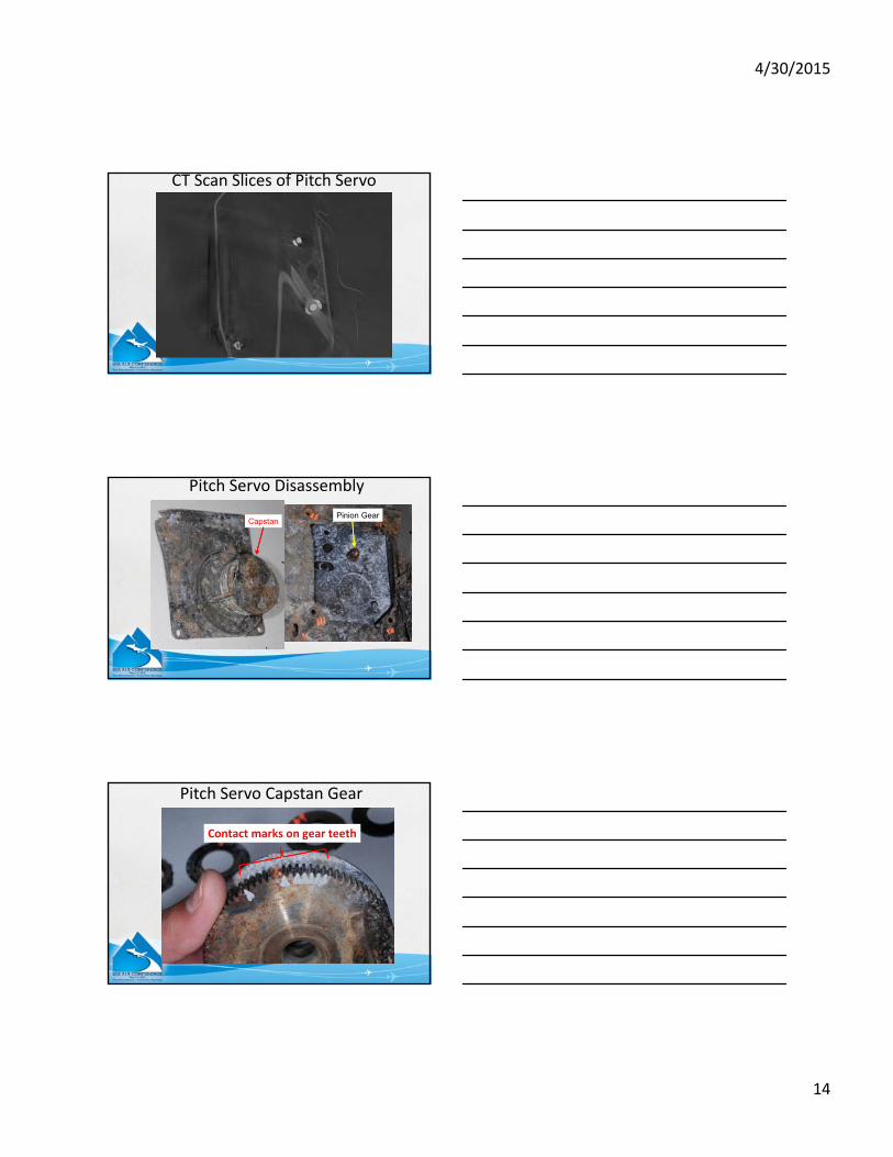
CT Scan Slices of Pitch Servo
CapstanPinion Gear
Pitch Servo Disassembly
Contact marks on gear teeth
Pitch Servo Capstan Gear
4/30/2015
15
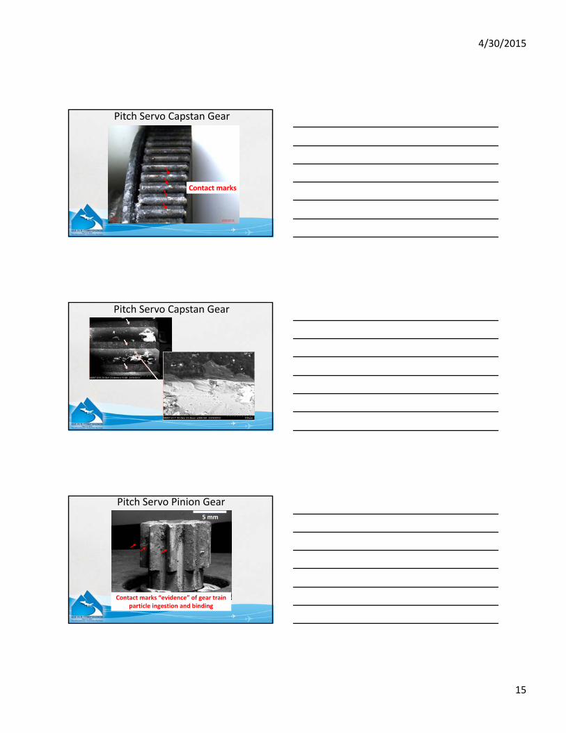
Contact marks on gear teeth
Contact marks
Pitch Servo Capstan Gear
Pitch Servo Capstan Gear
Contact marks “evidence” of gear train particle ingestion and binding
5 mm
Pitch Servo Pinion Gear
4/30/2015
16
Capstan Gear
Pinion Gear
CT Scan of Pitch Servo
Y_347
Capstan Gear
Pinion Gear
Y_682
122 μm = 0.0048 inch slices
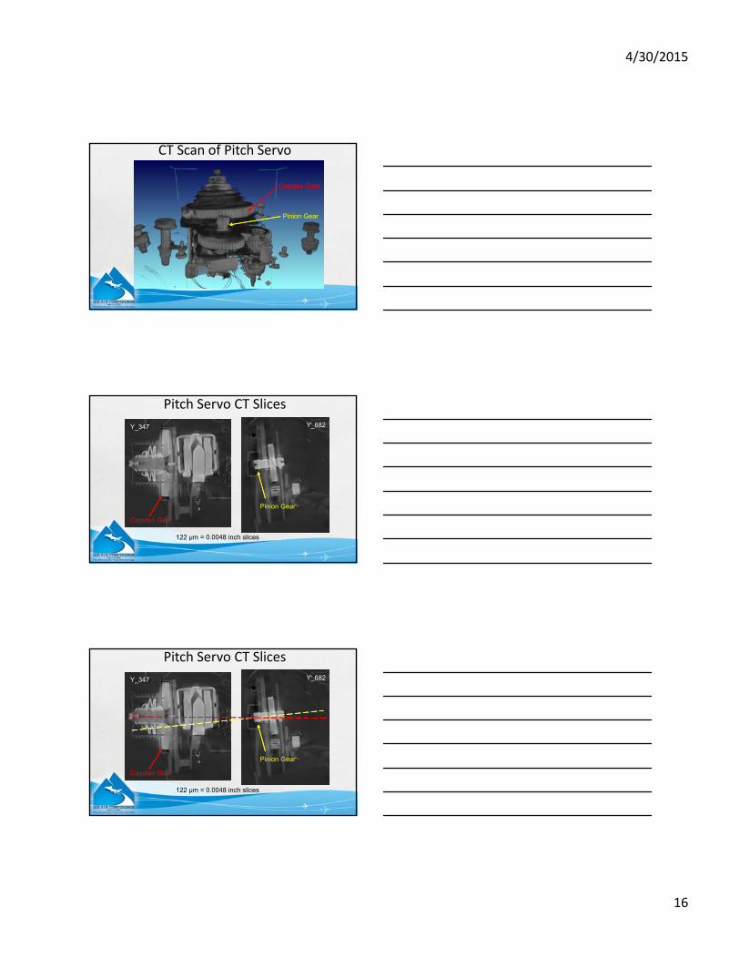
Pitch Servo CT Slices
Y_347
Capstan Gear
Pinion Gear
Y_682
122 μm = 0.0048 inch slices
Pitch Servo CT Slices
4/30/2015
17
Capstan Gear
Pinion Gear
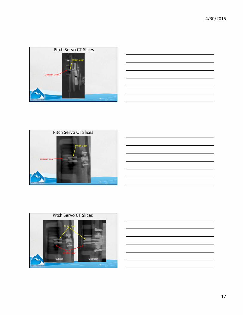
Pitch Servo CT Slices
Pitch Servo CT Slices
Capstan Gear
Pinion Gear
Y_682
Subject Exemplar
Capstan Gear
Pinion Gear
Pitch Servo CT Slices
4/30/2015
18
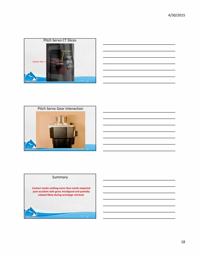
Pitch Servo CT Slices
Capstan Gear
Pinion Gear
Contact Points
Pitch Servo Gear Interaction
Contact marks nothing more than marks imparted post‐accident with gears misaligned and partially
rotated likely during wreckage retrieval.
Summary

4/30/2015
19
Y_347
Pinion Gear engaged here
Pitch Servo Capstan Mount Plate
Y_347
Pinion Gear engaged here
Position at disassembly
Shadow from hole –position during post-crash fire
Pitch Servo Capstan Gear
Overview
• X‐ray Computed Tomography (CT) of Parts
• Laser Scanning
• LiDAR
• New Aircraft Simulation Capabilities
4/30/2015
20
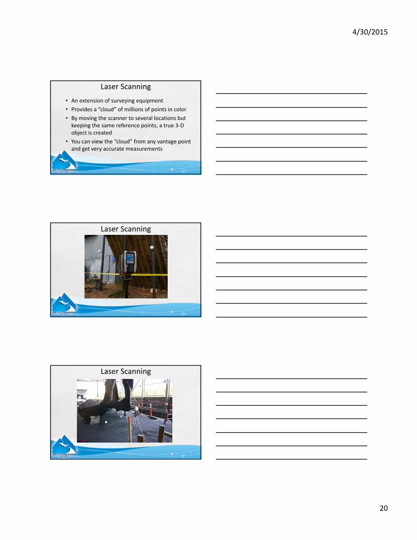
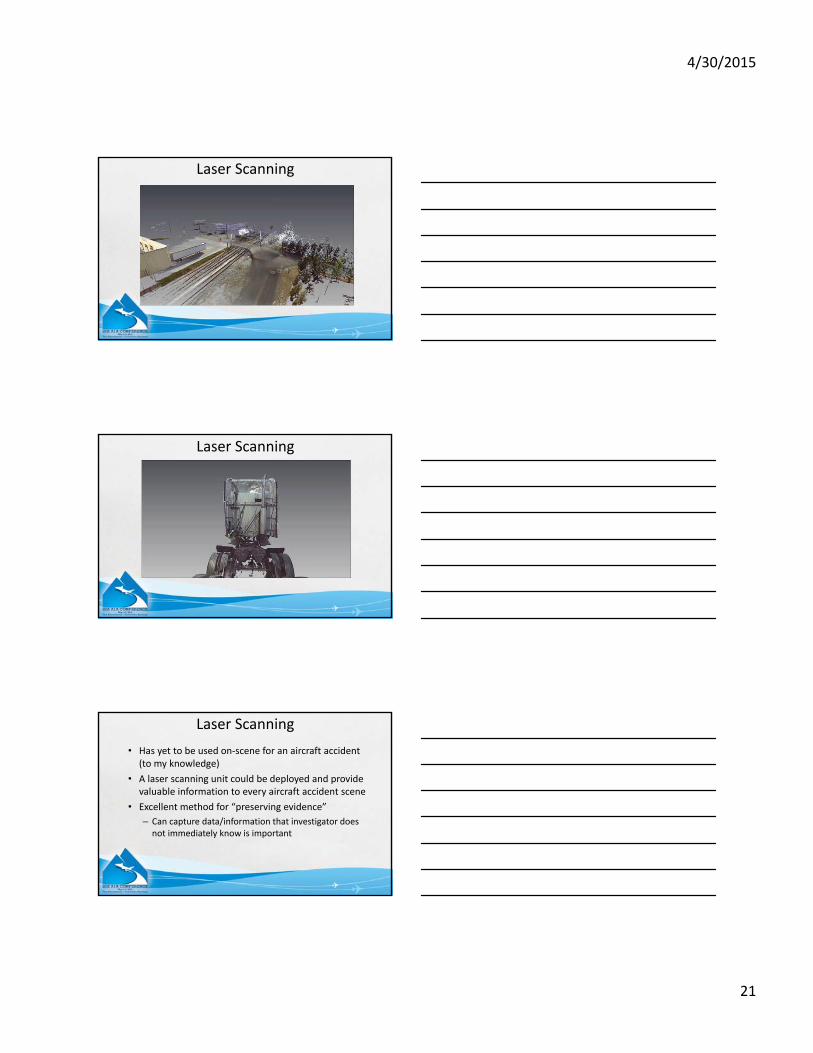
Laser Scanning
• An extension of surveying equipment
• Provides a “cloud” of millions of points in color
• By moving the scanner to several locations but keeping the same reference points, a true 3‐D object is created
• You can view the “cloud” from any vantage point and get very accurate measurements
Laser Scanning
Laser Scanning
4/30/2015
21
Laser Scanning
Laser Scanning
• Has yet to be used on‐scene for an aircraft accident (to my knowledge)
• A laser scanning unit could be deployed and provide valuable information to every aircraft accident scene
• Excellent method for “preserving evidence”
– Can capture data/information that investigator does not immediately know is important
Laser Scanning
4/30/2015
22
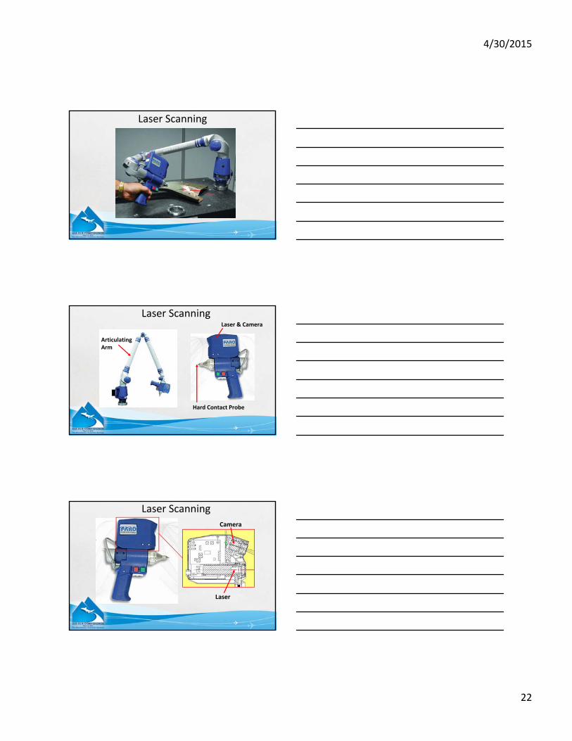
Laser Scanning
Laser Scanning
Articulating Arm
Hard Contact Probe
Laser & Camera
Laser Scanning
Laser
Camera
4/30/2015
23
Laser Scanning
Laser Scanning
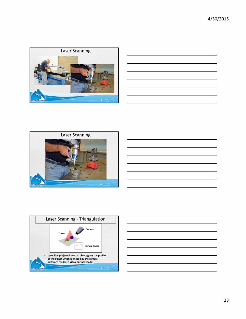
Laser
Camera
Camera Image
• Laser line projected over an object gives the profile of the object which is imaged by the camera
• Software renders a visual surface model
Laser Scanning ‐ Triangulation
4/30/2015
24
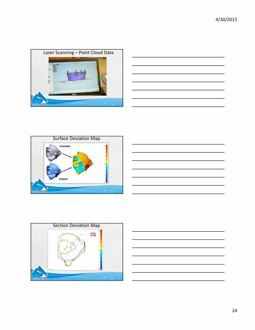
Laser Scanning – Point Cloud Data
Surface Deviation Map
Exemplar
Subject
Section Deviation Map

4/30/2015
25
Overview
• X‐ray Computed Tomography (CT) of Parts
• Laser Scanning
• LiDAR
• New Aircraft Simulation Capabilities
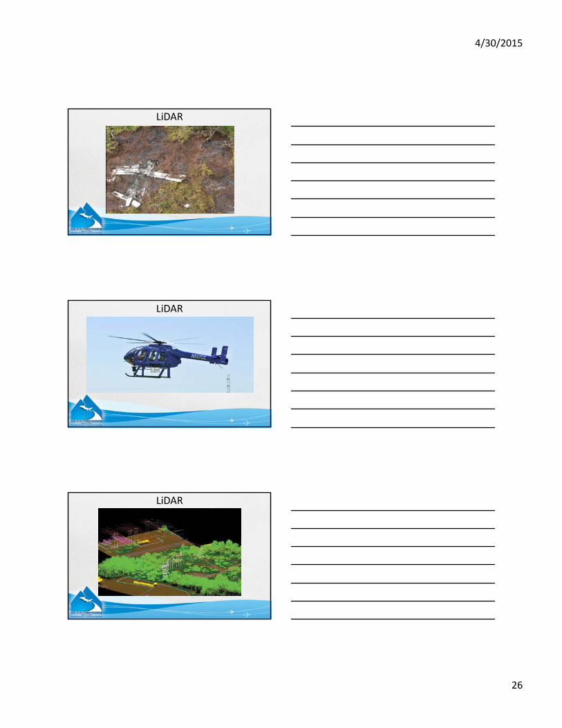
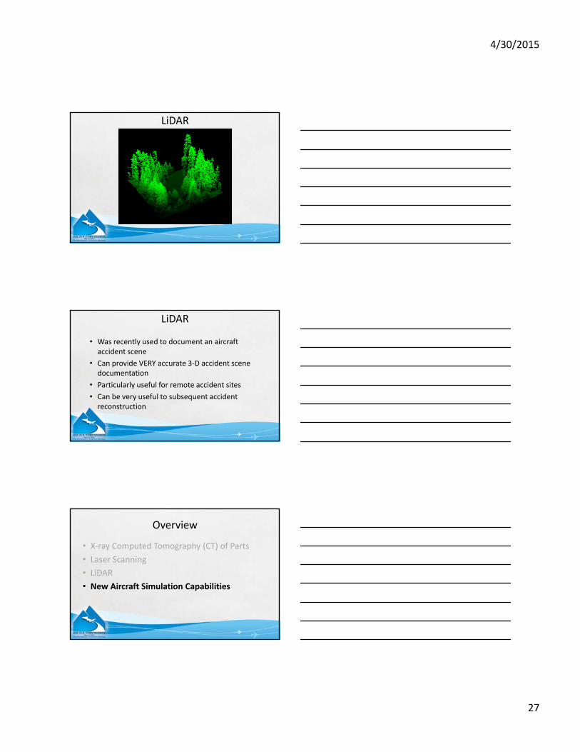
LiDAR
• Light Detection And Ranging
• Optical remote sensing technology that can measure the distance to targets by illuminating the target with laser light and analyzing the backscattered light
• Highly accurate vertical measurements
• Can get a 3‐D digital image of an accident scene, regardless of the site’s remoteness
LiDAR
4/30/2015
26
LiDAR
LiDAR
LiDAR
4/30/2015
27
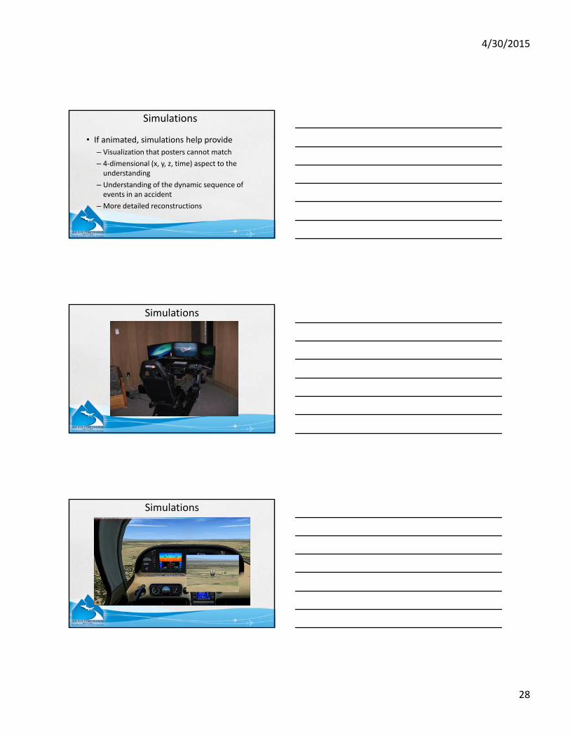
LiDAR
• Was recently used to document an aircraft accident scene
• Can provide VERY accurate 3‐D accident scene documentation
• Particularly useful for remote accident sites
• Can be very useful to subsequent accident reconstruction
LiDAR
Overview
• X‐ray Computed Tomography (CT) of Parts
• Laser Scanning
• LiDAR
• New Aircraft Simulation Capabilities
4/30/2015
28
Simulations
• If animated, simulations help provide
– Visualization that posters cannot match
– 4‐dimensional (x, y, z, time) aspect to the understanding
– Understanding of the dynamic sequence of events in an accident
– More detailed reconstructions
Simulations
Simulations
4/30/2015
29
Simulations – Radar Data
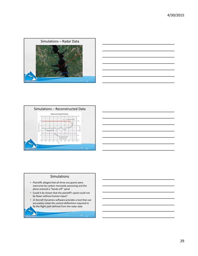
Simulations – Reconstructed Data
6000
7000
8000
9000
10000
11000
0
50
100
150
200
250
20:40 20:41 20:42 20:43 20:44 20:45 20:46 20:47 20:48 20:49
Alt
itu
de,
ft
MS
L
Cal
ibra
ted
Air
spee
d, k
t
UTC
Altitude and Airspeed Histories
Airspeed
Altitude
Approximate Airspeed for Stall Warning Horn and Autopilot Disconnect
• Plaintiffs alleged that all three occupants were overcome by carbon monoxide poisoning and the plane entered a “hands‐off” spiral
• Could it be shown that the plaintiff’s spiral could not be flown without human input?
• J2 Aircraft Dynamics software provides a tool that can accurately relate the control deflections required to fly the flight path defined from the radar data
Simulations
4/30/2015
30
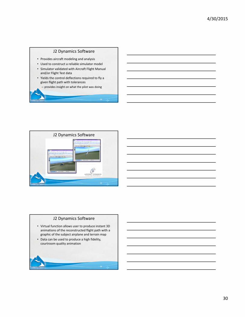
• Provides aircraft modeling and analysis
• Used to construct a reliable simulator model
• Simulator validated with Aircraft Flight Manual and/or Flight Test data
• Yields the control deflections required to fly a given flight path with tolerances
– provides insight on what the pilot was doing
J2 Dynamics Software
J2 Dynamics Software
• Virtual function allows user to produce instant 3D animations of the reconstructed flight path with a graphic of the subject airplane and terrain map
• Data can be used to produce a high fidelity, courtroom quality animation
J2 Dynamics Software

4/30/2015
31
Summary
• This has been a quick look at some of the tools that can be used in aircraft accident reconstruction
• Most of these tools came from other disciplines, so a broad view beyond the accident reconstruction community discipline is necessary
• Technology is changing rapidly – new tools continue to become available