Embed Size (px)
Citation preview
資料-00
Air Vent Valve Selection●
●
●
●
●
●
●
●
●
●
●
●
●
●
1.0
906090609012090
TA-3TA-3CTA-2TA-2CTA-5TA-5FTA-6
293299294299294294293
●
●
●
●
●
●
●
●
●
●
●
●
0.3
1.0
100
100
90
8035
TA-11TA-11LTA-18TA-18LTA-22TA-22LTA-16TA-16CVATA-16CVSTA-16LTAV-2TAV-3A
295295299299296296297298298297299299
ApplicationSte
am Water Oil
Max.WorkingPressure(MPa) Max.Temperature(˚C)
Model Page
288
P287-288_扉_空気抜弁 2011.3.15 11:26 AM ページ 2
A i r V e n t V a l v e
Air Ven
t Valve
Air Ven
t Valve
7-3, Futano-cho, Mizuho-ku, Nagoya, 467-0861, Japan Phone: 81-52-881-7199 Fax: 81-52-881-7201www.yoshitake.jp
289
空気-00
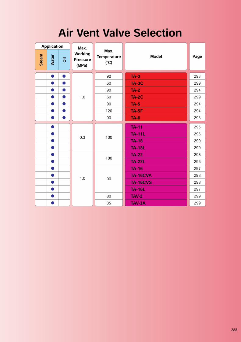
What is an Air Vent Valve ??Selection of Air Vent Valve
An air vent valve is a safety device that discharges air at the water supply piping in order to avoid airrelated problems in the water piping systems.
Major P
roducts
TA-3 Series TA-2・5 TAV-3A
Applica
tions
・Cold and hot water supply system・Hot water boiler・Solar hot water system・Other various devices
・Air conditioning system・Hot water heater appliance・Pressure tank
Purpos
es
・For protecting piping materials and systems from corrosion due to air (oxygen).・For preventing water splashing at faucet due to the existence of air.・For preventing noise resulted from the ingress of air into cold/hot water supply systems, air conditioning systems, and othersystems.・For the smooth startup and stable operation of water supply and other systems/devices through air discharge at the time of initialwater conveyance.
Types
Float type Float type W/ Quick ventilation Float type W/ Vacuum breaker
Discharges air in the piping continuously. Exhausts large quantity of air upon systemstart-up and release accumulated aircontinuously.Takes in air to reduce vacuum conditionand releases accumulated air if any.
P289-290_空気 2011.3.15 11:34 AM ページ 1

A i r V e n t V a l v e
Air Ven
t Valve
Air Ven
t Valve
7-3, Futano-cho, Mizuho-ku, Nagoya, 467-0861, Japan Phone: 81-52-881-7199 Fax: 81-52-881-7201www.yoshitake.jp
290
空気-12
Note for Selecting Air Vent ValveThe discharge amount depends on the model. Please refer to the following chart to select a modeladequate for the required discharge amount.
The difference between air vent valves with and without quick exhaust mechanism appears during theoperation at low pressure up to 0.015 MPa. By exhausting large amount of air from the piping at lowpressure, the valve ensures smooth initial water supply.
200
180
160
140
120
100
80
60
40
20
0
L/m
in
0 0.2 0.4 0.6 0.8 1
MPa
Air vent valve discharge amount
TA-3
TA-16
TA-22
220
200
180
160
140
120
100
80
60
40
20
00.1 0.01 0.02 0.03 0.04 0.050.2 0.3 0.4 0.5 0.6 0.7 0.8 0.9 1.0
120
110
100
90
80
70
60
50
40
30
20
10
0
Exh
au
st
cap
acit
y L
/min
(sta
nd
ard
co
nd
itio
n)
Exh
au
st
cap
acit
y L
/min
(sta
nd
ard
co
nd
itio
n)
Pressure MPa Pressure MPa
Discharge Amount
Feature of Quick Exhaust Mechanism
P289-290_空気 2011.3.10 11:18 PM ページ 2
A i r V e n t V a l v e
Air Ven
t Valve
Air Ven
t Valve
7-3, Futano-cho, Mizuho-ku, Nagoya, 467-0861, Japan Phone: 81-52-881-7199 Fax: 81-52-881-7201www.yoshitake.jp
291
空気-13
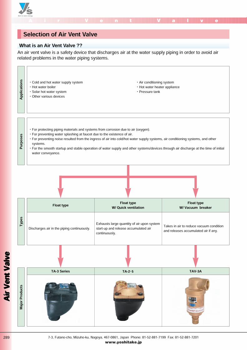
Note for Selecting Air Vent ValveAn air vent valve with vacuum breaker operates in the same manner as an air vent valve but has anupgraded air intake function that works when negative pressure is generated. It prevents a backflow froma system or unit to which water is supplied by promptly eliminating negative pressure.
One of the probable causes of the generation of maximum negative pressure inside water supply pipingis a large water leakage due to damage to piping. So, negative pressure no longer occurs if a largerquantity of air than this water leakage can be introduced into the piping.The air intake performance standards of Scandinavian countries (established by N. Lindblad, SwedishWater & Wastewater Association) take the same view about the intake air quantity. The Nagoya CityWaterworks & Sewerage Bureau and some other business units set an intake air quantity for eachnominal size of vertical piping based on Scandinavian countries' view.
An“air vent valve”has been installed at the top ofvertical water supply piping for the purpose ofdischarging air.In this case, however, if the pressure inside pipingdrops because of temporary suspension of watersupply or an accident, the pressure at the top of thevertical piping becomes negative, which may cause thephenomenon of a backflow (inverted siphon) within thebuilding.For this reason, the top of the vertical piping requiresan“air vent valve with vacuum breaker”that has botha function of introducing into the piping a sufficientquantity of air to eliminate negative pressure, and afunction capable of discharging air under pressure.・ Top of vertical piping in collective housing andbuildings・ Top of vertical piping connected to direct boostingwater supply lines
M
M
M
M
M
M
M
M
M
BP
Pressure
reducing valve
for individual
water supply
Air vent valve
with vacuum breaker
Booster pump
for water supply
Backflow prevention
equipment
of pressure reducing type
●Required intake air quantity (The Nagoya City Waterworks & Sewerage Bureau)∆P = –2.9 kPa
Intake air quantity [L/min (standard condition)]
Intake air quantity [L/sec (standard condition)]
Size at the top of water supply piping 20
90
1.5
25
150
2.5
30
240
4.0
40
420
7.0
50
840
14
Air Vent Valve with Vacuum Breaker
Necessity of Air Vent Valves with Vacuum Breaker
View about Intake Air Quantity
P291-292_空気 2011.3.10 11:19 PM ページ 1
A i r V e n t V a l v e
Air Ven
t Valve
Air Ven
t Valve
7-3, Futano-cho, Mizuho-ku, Nagoya, 467-0861, Japan Phone: 81-52-881-7199 Fax: 81-52-881-7201www.yoshitake.jp
292
空気-14
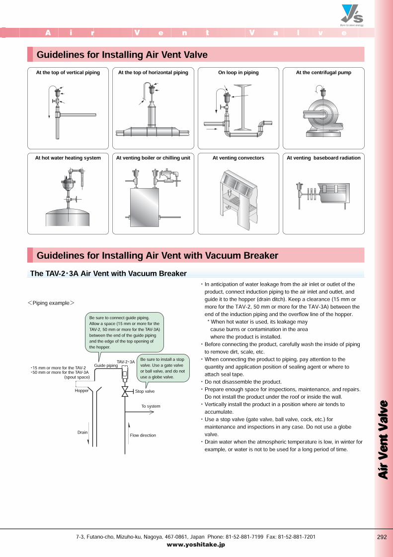
Guidelines for Installing Air Vent Valve
Guidelines for Installing Air Vent with Vacuum Breaker
At the top of vertical piping
At hot water heating system
At the top of horizontal piping On loop in piping At the centrifugal pump
At venting boiler or chilling unit At venting convectors At venting baseboard radiation
<Piping example>・ In anticipation of water leakage from the air inlet or outlet of theproduct, connect induction piping to the air inlet and outlet, andguide it to the hopper (drain ditch). Keep a clearance (15 mm ormore for the TAV-2, 50 mm or more for the TAV-3A) between theend of the induction piping and the overflow line of the hopper.* When hot water is used, its leakage maycause burns or contamination in the areawhere the product is installed.・ Before connecting the product, carefully wash the inside of pipingto remove dirt, scale, etc.・ When connecting the product to piping, pay attention to thequantity and application position of sealing agent or where toattach seal tape.・ Do not disassemble the product.・ Prepare enough space for inspections, maintenance, and repairs.Do not install the product under the roof or inside the wall.・ Vertically install the product in a position where air tends toaccumulate.・ Use a stop valve (gate valve, ball valve, cock, etc.) formaintenance and inspections in any case. Do not use a globevalve.・ Drain water when the atmospheric temperature is low, in winter forexample, or water is not to be used for a long period of time.
The TAV-2・3A Air Vent with Vacuum Breaker
Be sure to connect guide piping.Allow a space (15 mm or more for the TAV-2, 50 mm or more for the TAV-3A) between the end of the guide piping and the edge of the top opening of the hopper.TAV-2・3A
(spout space)・15 mm or more for the TAV-2・50 mm or more for the TAV-3A
Drain
Hopper
Flow direction
Guide piping
To systemStop valve
Be sure to install a stop valve. Use a gate valve or ball valve, and do not use a globe valve.
P291-292_空気 2011.3.10 11:19 PM ページ 2
A i r V e n t V a l v e
Air Ven
t Valve
Air Ven
t Valve
7-3, Futano-cho, Mizuho-ku, Nagoya, 467-0861, Japan Phone: 81-52-881-7199 Fax: 81-52-881-7201www.yoshitake.jp
293
空気-01
WaterWater BronzeDuctile iron
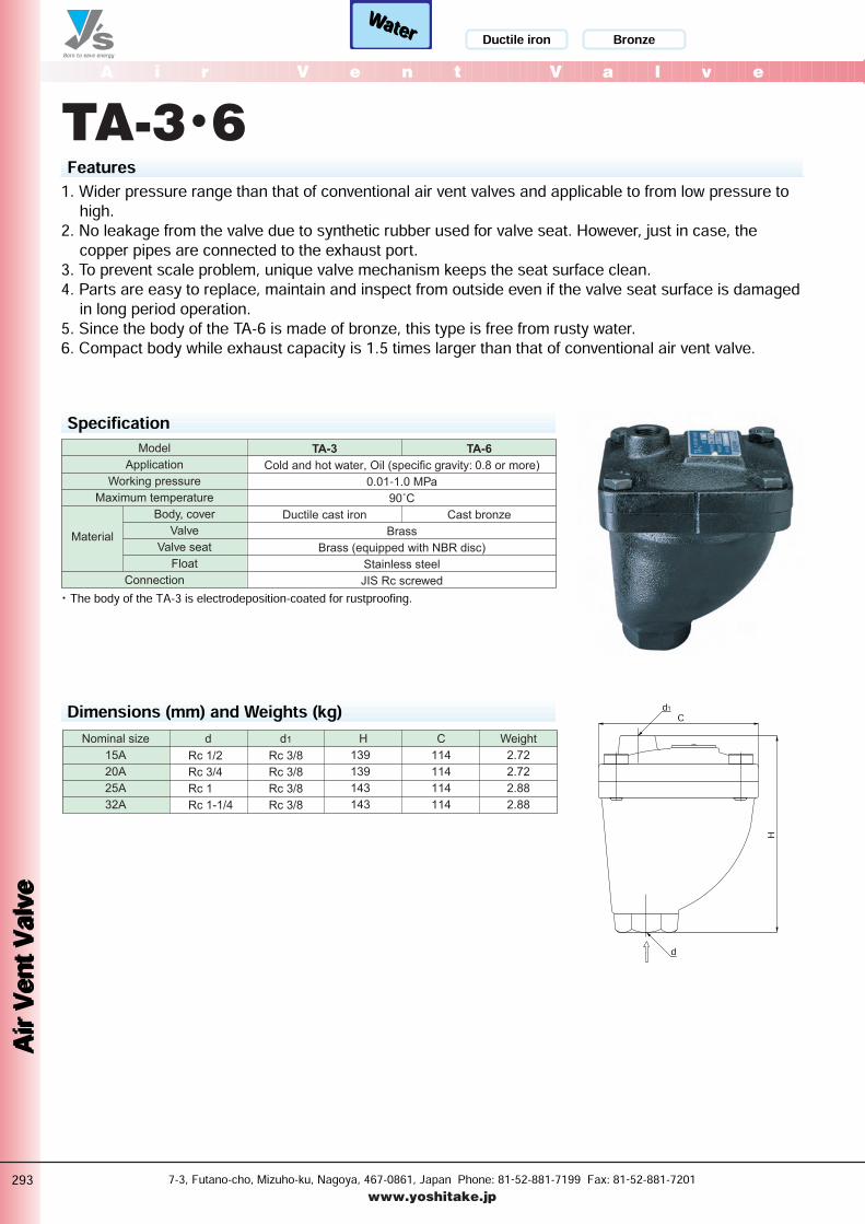
TA-3・6
SpecificationCold and hot water, Oil (specific gravity: 0.8 or more)
0.01-1.0 MPa
90˚C
Brass
Brass (equipped with NBR disc)
Stainless steel
JIS Rc screwed
Ductile cast iron Cast bronze
TA-6TA-3Model
Application
Working pressure
Maximum temperature
Body, cover
Valve
Valve seat
Float
Connection
Material
Features1. Wider pressure range than that of conventional air vent valves and applicable to from low pressure tohigh.2. No leakage from the valve due to synthetic rubber used for valve seat. However, just in case, thecopper pipes are connected to the exhaust port.3. To prevent scale problem, unique valve mechanism keeps the seat surface clean.4. Parts are easy to replace, maintain and inspect from outside even if the valve seat surface is damagedin long period operation.5. Since the body of the TA-6 is made of bronze, this type is free from rusty water.6. Compact body while exhaust capacity is 1.5 times larger than that of conventional air vent valve.
・ The body of the TA-3 is electrodeposition-coated for rustproofing.
Dimensions (mm) and Weights (kg)Nominal size
15A
20A
25A
32A
Weightd
Rc 1/2
Rc 3/4
Rc 1
Rc 1-1/4
d1
Rc 3/8
Rc 3/8
Rc 3/8
Rc 3/8
H C
114
114
114
114
139
139
143
143
2.72
2.72
2.88
2.88
d
C
H
d1
P293-294_空気 2011.3.10 11:19 PM ページ 1

WaterWaterA i r V e n t V a l v e
Air Ven
t Valve
Air Ven
t Valve
7-3, Futano-cho, Mizuho-ku, Nagoya, 467-0861, Japan Phone: 81-52-881-7199 Fax: 81-52-881-7201www.yoshitake.jp
294
空気-02
Bronze
TA-2・5・5F
SpecificationCold and hot water, Oil (specific gravity: 0.8 or more)
0.01-1.0 MPa
0.01 MPa or less
Bronze
Brass
Stainless steel
JIS Rc screwed
120˚C
Brass
(equipped with FKM disc)
90˚C
Brass
(equipped with NBR disc)
Cast bronzeDuctile cast iron
TA-5FTA-2 TA-5Model
Application
Working pressure
Maximum temperature
Operating pressure range of quick exhaust valve
Body
Cover
Valve
Sub valve
Float
Connection
Material
Features1. Equipped with a quick exhaust mechanism, air inside piping can be quickly discharged at the time ofinitial water supply, ensuring smooth water supply.2. Wider pressure range than that of conventional air vent valves and applicable to from low pressure tohigh.3. Parts are easy to replace, maintain and inspect from outside even if the valve seat surface is damagedin long period operation.4. Since the body of the TA-5 and TA-5F is made of bronze, these types are free from rusty water.5. Sucks in air promptly and automatically when pressure becomes negative in piping or tank, preventingdamage to piping components by negative pressure.
・ The body of the TA-2 is electrodeposition-coated for rustproofing.
Dimensions (mm) and Weights (kg)Nominal size
15A
20A
25A
32A
Weightd
Rc 1/2
Rc 3/4
Rc 1
Rc 1-1/4
d1
Rc 3/8
Rc 3/8
Rc 3/8
Rc 3/8
H C
114
114
114
114
153
153
157
157
3.18
3.18
3.22
3.22
C
H
d
d1
Ductile iron
P293-294_空気 2011.3.10 11:19 PM ページ 2
A i r V e n t
Air Ven
t Valve
Air Ven
t Valve
7-3, Futano-cho, Mizuho-ku, Nagoya, 467-0861, Japan Phone: 81-52-881-7199 Fax: 81-52-881-7201www.yoshitake.jp
000
空気-00
WaterWater Brass
d
Capable of turning 360°
φ 6
H151
18.5H
φ 37
H
d
1651
H1
A i r V e n t V a l v e
Air Ven
t Valve
Air Ven
t Valve
295
空気-05
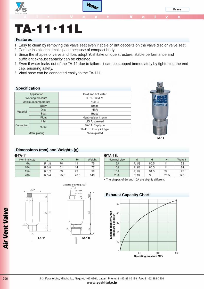
TA-11・11LFeatures1. Easy to clean by removing the valve seat even if scale or dirt deposits on the valve disc or valve seat.2. Can be installed in small space because of compact body.3. Since the shapes of valve and float adopt Yoshitake unique structure, stable performance andsufficient exhaust capacity can be obtained.4. Even if water leaks out of the TA-11 due to failure, it can be stopped immediately by tightening the endcap, ensuring safety.5. Vinyl hose can be connected easily to the TA-11L.
SpecificationCold and hot water
0.01-0.3 MPa
100˚C
Brass
NBR
Brass
Heat-resistant resin
JIS R screwed
TA-11: Cap type
TA-11L: Hose joint type
Nickel-plated
Application
Working pressure
Maximum temperature
Body
Disc
Seat
Float
Inlet
Outlet
Metal plating
Connection
Material
Dimensions (mm) and Weights (g)Nominal size
6A
10A
15A
20A
Weightd
R 1/8
R 3/8
R 1/2
R 3/4
H
78
81
89
95.5
H1
11
14
22
28.5
75
77
98
148
●TA-11Nominal size
6A
10A
15A
20A
Weightd
R 1/8
R 3/8
R 1/2
R 3/4
H
80.5
83.5
91.5
98
H1
11
14
22
28.5
72
74
95
145
●TA-11L
・ The shapes of 6A and 10A are slightly different.
Exhaust Capacity Chart
0.1 0.2 0.3
50
40
30
20
10
0
Exh
au
st
cap
acit
y L
/min
(sta
nd
ard
co
nd
itio
n)
Operating pressure MPa
TA-11
TA-11LTA-11
P295-296_空気 2011.3.10 11:20 PM ページ 1
WaterWaterA i r V e n t V a l v e
Air Ven
t Valve
Air Ven
t Valve
7-3, Futano-cho, Mizuho-ku, Nagoya, 467-0861, Japan Phone: 81-52-881-7199 Fax: 81-52-881-7201www.yoshitake.jp
296
空気-06
Bronze
d H1H2
18.5H
Capable of turning 360°
φ 6
φ D
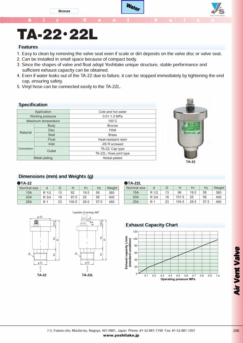
TA-22・22LFeatures1. Easy to clean by removing the valve seat even if scale or dirt deposits on the valve disc or valve seat.2. Can be installed in small space because of compact body.3. Since the shapes of valve and float adopt Yoshitake unique structure, stable performance andsufficient exhaust capacity can be obtained.4. Even if water leaks out of the TA-22 due to failure, it can be stopped immediately by tightening the endcap, ensuring safety.5. Vinyl hose can be connected easily to the TA-22L.
SpecificationCold and hot water
0.01-1.0 MPa
100˚C
Bronze
FKM
Brass
Heat-resistant resin
JIS R screwed
TA-22: Cap type
TA-22L: Hose joint type
Nickel-plated
Application
Working pressure
Maximum temperature
Body
Disc
Seat
Float
Inlet
Outlet
Metal plating
Connection
Material
Dimensions (mm) and Weights (g)Nominal size
15A
20A
25A
Weightd
R 1/2
R 3/4
R 1
D
13
18
23
H
92
97.5
100.5
H1
19.5
25
28.5
H2
58
58
57.5
360
400
460
●TA-22Nominal size
15A
20A
25A
Weightd
R 1/2
R 3/4
R 1
D
13
18
23
H
96
101.5
104.5
H1
19.5
25
28.5
H2
58
58
57.5
360
400
460
●TA-22L
d H1H2
14.5H
φ 52
φ D
Exhaust Capacity Chart
0.1 0.2 0.3 0.4 0.5 0.6 0.7 0.8 0.9 1.0
120
100
80
60
40
20
0
Exh
au
st
cap
acit
y L
/min
(sta
nd
ard
co
nd
itio
n)
Operating pressure MPa
TA-22
TA-22LTA-22
P295-296_空気 2011.3.10 11:20 PM ページ 2

H1
d
H
φ 6 (Hose bore)φ 80
d
H
φ 80
A i r V e n t V a l v e
Air Ven
t Valve
Air Ven
t Valve
7-3, Futano-cho, Mizuho-ku, Nagoya, 467-0861, Japan Phone: 81-52-881-7199 Fax: 81-52-881-7201www.yoshitake.jp
297
空気-07
WaterWater Stainless steel
TA-16・16LFeatures1. All parts, except for the valve disc, gasket, L-shaped hose joint (TA-16L), are made of stainless steel,offering high resistance to corrosion and durability.2. Wide working pressure range (0.01 to 1.0 MPa) ensures stable exhaust capacity.3. Can be installed in small space because of compact body.4. Outstanding sealability offered by fluororubber valve disc.5. The TA-16 can be connected to any exhaust piping easily by attaching optional piping connectionparts.Specification
Cold and hot water
0.01-1.0 MPa
90˚C
Stainless steel
FKM
FKM
Stainless steel
JIS R screwed
JIS Rc screwed Hose joint type
TA-16LTA-16Model
Application
Working pressure
Maximum temperature
Body, cover
Valve disc
Gasket
Float
Inlet
Outlet
Material
Connection
Dimensions (mm) and Weights (g)Nominal size
15A
20A
25A
Weightd
R 1/2
R 3/4
R 1
H
118
120
124.5
660
680
740
●TA-16Nominal size
15A
20A
25A
Weightd
R 1/2
R 3/4
R 1
H1 H
136
138
144
143
145
149.5
700
720
780
●TA-16L
Exhaust Capacity Chart
0.1 0.2 0.3 0.4 0.5 0.6 0.7 0.8 0.9 1.0
80
70
60
50
40
30
20
10
0
Exh
au
st
cap
acit
y L
/min
(sta
nd
ard
co
nd
itio
n)
Operating pressure MPa
OptionAvailable with manual valves, swivel joints (capable of turning 360 degrees), etc. (made of brass) as piping connection parts for the exhaustports of air vent valves.
・For other connection parts, please contact us.
TA-16
TA-16LTA-16
●L-shaped hose joint (R 1/4 x φ 6) ●Manual valve with
copper joint (R 1/4 x φ 8)
●Manual valve with hose joint (R 1/4 x φ 6)
●Swivel joint (R 1/4 x Rc 1/4) ●Swivel copper pipe
joint (R 1/4 x φ 8)
●Swivel hose joint (R 1/4 x φ 6)
P297-298_空気 2011.3.10 11:21 PM ページ 1
WaterWaterA i r V e n t V a l v e
Air Ven
t Valve
Air Ven
t Valve
7-3, Futano-cho, Mizuho-ku, Nagoya, 467-0861, Japan Phone: 81-52-881-7199 Fax: 81-52-881-7201www.yoshitake.jp
298
空気-08
Stainless steel
d
H
φ 80
H1
d
H
φ 80
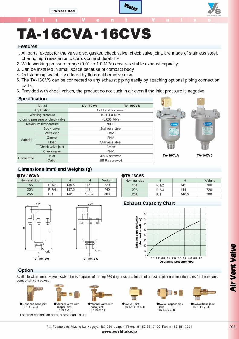
TA-16CVA・16CVSFeatures1. All parts, except for the valve disc, gasket, check valve, check valve joint, are made of stainless steel,offering high resistance to corrosion and durability.2. Wide working pressure range (0.01 to 1.0 MPa) ensures stable exhaust capacity.3. Can be installed in small space because of compact body.4. Outstanding sealability offered by fluororubber valve disc.5. The TA-16CVS can be connected to any exhaust piping easily by attaching optional piping connectionparts.6. Provided with check valves, the product do not suck in air even if the inlet pressure is negative. Specification
Cold and hot water
0.01-1.0 MPa
–0.005 MPa
90˚C
Stainless steel
FKM
FKM
Stainless steel
Brass
FKM
JIS R screwed
JIS Rc screwed
TA-16CVSTA-16CVAModel
Application
Working pressure
Closing pressure of check valve
Maximum temperature
Body, cover
Valve disc
Gasket
Float
Check valve joint
Check valve
Inlet
Outlet
Material
Connection
Dimensions (mm) and Weights (g)Nominal size
15A
20A
25A
Weightd
R 1/2
R 3/4
R 1
H1 H
135.5
137.5
142
146
148
152.5
720
740
800
●TA-16CVANominal size
15A
20A
25A
Weightd
R 1/2
R 3/4
R 1
H
142
144
148.5
700
720
780
●TA-16CVS
Exhaust Capacity Chart
0.1 0.2 0.3 0.4 0.5 0.6 0.7 0.8 0.9 1.0
80
70
60
50
40
30
20
10
0
Exh
au
st
cap
acit
y L
/min
(sta
nd
ard
co
nd
itio
n)
Operating pressure MPa
TA-16CVA TA-16CVS
TA-16CVA TA-16CVSOption
Available with manual valves, swivel joints (capable of turning 360 degrees), etc. (made of brass) as piping connection parts for the exhaustports of air vent valves.
・For other connection parts, please contact us.●L-shaped hose joint (R 1/4 x φ 6) ●Manual valve with
copper joint (R 1/4 x φ 8)
●Manual valve with hose joint (R 1/4 x φ 6)
●Swivel joint (R 1/4 x Rc 1/4) ●Swivel copper pipe
joint (R 1/4 x φ 8)
●Swivel hose joint (R 1/4 x φ 6)
P297-298_空気 2011.3.15 11:38 AM ページ 2


![Air Cond – Press - Vent - SmartCockpit · TAM MSN 0243-2393 2445 Airbus A319-320-321 [Air Cond - Press - Vent] Page 2](https://img.pdfslide.us/doc/110x75/5b47be0e7f8b9aa4148d0f34/air-cond-press-vent-tam-msn-0243-2393-2445-airbus-a319-320-321-air.jpg)