Embed Size (px)
Citation preview
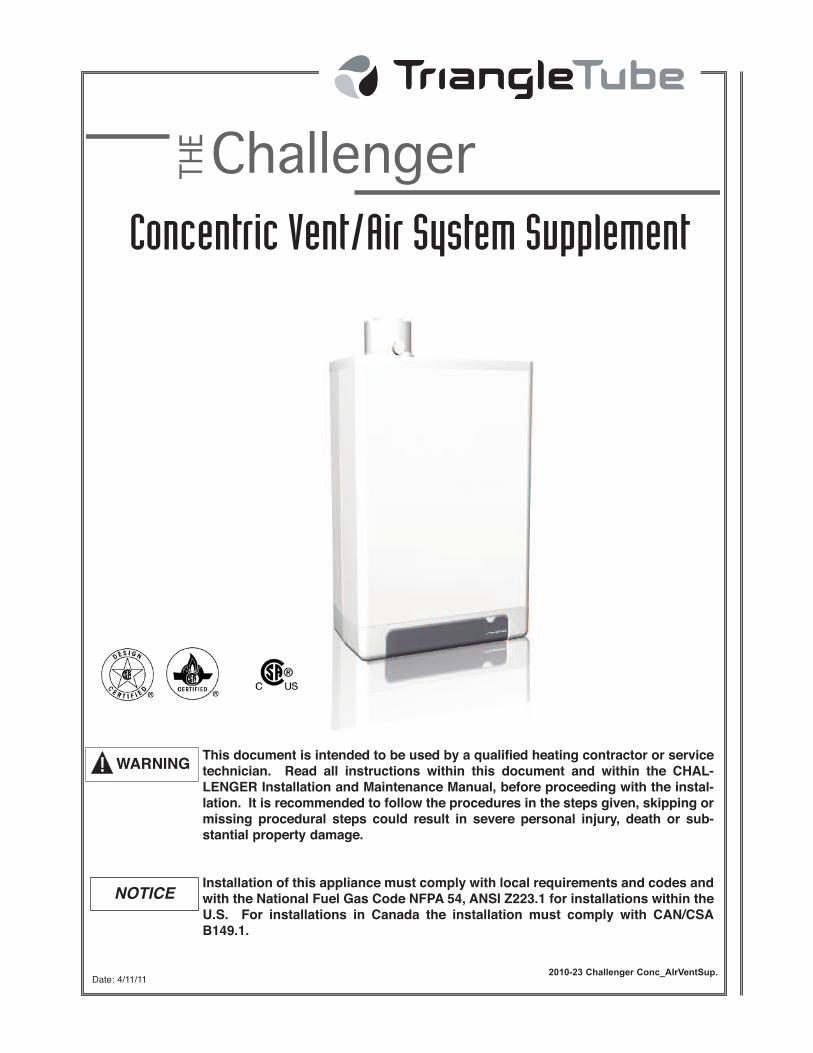
2010-23 Challenger Conc_AIrVentSup.
This document is intended to be used by a qualified heating contractor or service
technician. Read all instructions within this document and within the CHAL-
LENGER Installation and Maintenance Manual, before proceeding with the instal-
lation. It is recommended to follow the procedures in the steps given, skipping or
missing procedural steps could result in severe personal injury, death or sub-
stantial property damage.
Installation of this appliance must comply with local requirements and codes and
with the National Fuel Gas Code NFPA 54, ANSI Z223.1 for installations within the
U.S. For installations in Canada the installation must comply with CAN/CSA
B149.1.
Concentric Vent/Air System Supplement
Date: 4/11/11
NOTICE
WARNING
Table of Contents
i
PRODUCT AND SAFETY INFORMATION
Definitions. . . . . . . . . . . . . . . . . . . . . . . . . . . . . . . . . . . . . . . . . . . . . . . . . . . 1
SECTION I - PRE-INSTALLATION ITEMS
General Requirements. . . . . . . . . . . . . . . . . . . . . . . . . . . . . . . . . . . . . . . . . . 2
Vent/Air System Kit Components . . . . . . . . . . . . . . . . . . . . . . . . . . . . . . . . 2
Assembled Vent/Air System Kit Dimensions. . . . . . . . . . . . . . . . . . . . . . . . 3
Optional Vent/Air System Components . . . . . . . . . . . . . . . . . . . . . . . . . . . . 3
SECTION II - VENT/AIR SYSTEM INSTALLATION
Vent/Air System Clearance Requirements . . . . . . . . . . . . . . . . . . . . . . . . . . 4
Determine Termination Location . . . . . . . . . . . . . . . . . . . . . . . . . . . . . . . . . 4
Vent/Air System Joint Assembly . . . . . . . . . . . . . . . . . . . . . . . . . . . . . . . . . 5
Termination Installation - Horizontal . . . . . . . . . . . . . . . . . . . . . . . . . . . . . . 6
Termination Installation - Vertical . . . . . . . . . . . . . . . . . . . . . . . . . . . . . . . . 7
Cutting Termination Fitting or CCVPIP04 to Length . . . . . . . . . . . . . . . . . 7
Adjustable Length Vent/Air System Pipe. . . . . . . . . . . . . . . . . . . . . . . . . . . 8
Fire Stop Support Plate. . . . . . . . . . . . . . . . . . . . . . . . . . . . . . . . . . . . . . . . . 8
Multiple Vent/Air System Terminations . . . . . . . . . . . . . . . . . . . . . . . . . . . . 8
SECTION III - MAINTENANCE PROCEDURES
Inspect Vent/Air System . . . . . . . . . . . . . . . . . . . . . . . . . . . . . . . . . . . . . . . . 9

Product & Safety Information
1
Indicates a potentially hazardous situationwhich, if ignored, can result in death, seri-ous injury or substantial property damage.
Indicates special instructions on installa-tion, operation or maintenance, which areimportant to appliance but not related topersonal injury hazards.
NOTICEWARNING
The following terms are used throughout this manual to bring attention to the presence of potentialhazards or to important information concerning the appliance.
Triangle Tube reserves the right to modify the technical specifications and components of its prod-ucts without prior notice.
NOTICE
Definitions
This Vent/Air System is listed to ULCS636 as Type BH Class IIC Vent System with a 110ºC (230ºF)maximum flue temperature rating.
NOTICE
Pre-Installation Items
2
SECTION I - Pre-Installation Items
General Requirements
Installation of the vent/air system must comply withlocal codes and requirements and with the NationalFuel Gas Code NFPA 54, ANSI Z223.1 for installa-tions in the U.S. For Installations in Canada, theinstallation must comply with CAN/CSA B149.1.
The vent/air system must be fully constructed usingONLY the CHALLENGER Concentric Vent/AirSystem components from Triangle Tube. Do notmix other vent components or joining methods fromother manufacturers.
Do not mix vent components or joining meth-ods from any other vent manufacturer withTriangle Tube’s CHALLENGER ConcentricVent/Air System. Failure to comply with thisrequirement could cause vent failure result-ing in leakage of flue products into the livingspace of the building.
WARNING
Do not connect more than a single appliance intothe vent/air system.
All penetrations of the vent/air system through ceil-ings, floors, walls or roofs must be properly firestopped. The installer must comply with all localcodes and requirements regarding fire stops andvent/air penetrations.
The vent/air system must not penetrate or be routedthrough any active vent system or chimney.
Vent/Air System Kit Components
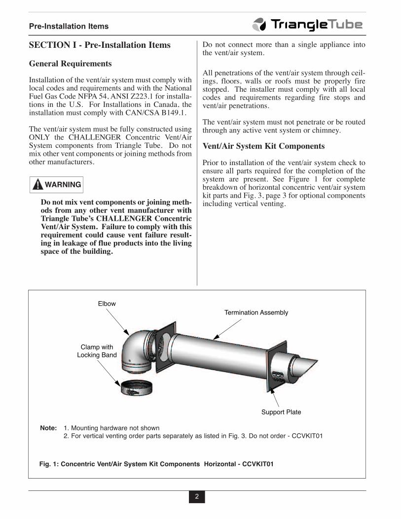
Prior to installation of the vent/air system check toensure all parts required for the completion of thesystem are present. See Figure 1 for completebreakdown of horizontal concentric vent/air systemkit parts and Fig. 3, page 3 for optional componentsincluding vertical venting.
Termination AssemblyElbow
Clamp withLocking Band
Support Plate
Fig. 1: Concentric Vent/Air System Kit Components Horizontal - CCVKIT01
Note: 1. Mounting hardware not shown2. For vertical venting order parts separately as listed in Fig. 3. Do not order - CCVKIT01
Pre-Installation Items
3
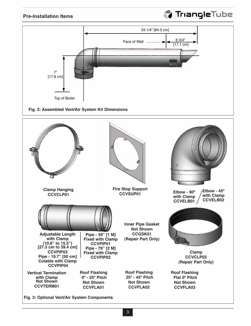
33 1/4” [84.5 cm]
Face of Wall
Top of Boiler
6 3/4” [17.1 cm]
7”[17.8 cm]
Fig. 2: Assembled Vent/Air System Kit Dimensions
Fig. 3: Optional Vent/Air System Components
Clamp Hanging
CCVCLP01
Clamp
CCVCLP02
(Repair Part Only)
Adjustable Lengthwith Clamp
(10.8” to 15.5”)[27.3 cm to 39.4 cm]
CCVPIP03Pipe - 19.7” [50 cm]Cutable with Clamp
CCVPIP04
Elbow - 90ºwith ClampCCVELB01
Elbow - 45ºwith ClampCCVELB02
Pipe - 39” [1 M]Fixed with Clamp
CCVPIP01Pipe - 79” [2 M]
Fixed with ClampCCVPIP02PSVPIP02
Fire Stop Support
CCVSUP01
Inner Pipe Gasket
Not Shown
CCGSK01
(Repair Part Only)
PSVGSK01
Vertical Terminationwith Clamp Not Shown
CCVTERM01
Roof Flashing
0º - 25º Pitch
Not Shown
CCVFLA01
Roof Flashing
25º - 45º Pitch
Not Shown
CCVFLA02
Roof Flashing
Flat 0º Pitch
Not Shown
CCVFLA03
4
h. Locate the vent and combustin air termina-tions in a manner to protect from damage byforeign objects, such as stones, balls, orbuildup of leaves or sediment.
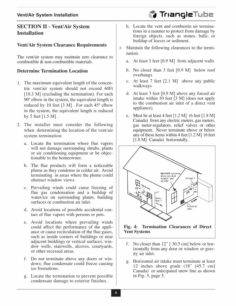
3. Maintain the following clearances to the termi-
nation:
a. At least 3 feet [0.9 M] from adjacent walls
b. No closer than 3 feet [0.9 M] below roofoverhangs
c. At least 7 feet [2.1 M] above any publicwalkways
d. At least 3 feet [0.9 M] above any forced airintake within 10 feet [3 M] (does not applyto the combustion air inlet of a direct ventappliance).
e. Must be at least 4 feet [1.2 M] (6 feet [1.8 M]Canada) from any electric meters, gas meters,gas meter-regulators, relief valves or otherequipment. Never terminate above or belowany of these items within 4 feet [1.2 M] (6 feet[1.8 M] Canada) horizontally.
f. No closer than 12” [ 30.5 cm] below or hor-izontally from any door or window or grav-ity air inlet.
g. Horizontal air intake must terminate at least12 inches above grade (18” [45.7 cm]Canada) or anticipated snow line as shownin Fig. 5, page 5.
Vent/Air System Installation
SECTION II - Vent/Air System
Installation
Vent/Air System Clearance Requirements
The vent/air system may maintain zero clearance tocombustible & non-combustible materials.
Determine Termination Location
1. The maximum equivalent length of the concen-
tric vent/air system should not exceed 60Ft
[18.3 M] (excluding the termination). For each
90º elbow in the system, the equivalent length is
reduced by 10 feet [3 M] . For each 45º elbow
in the system, the equivalent length is reduced
by 5 feet [1.5 M] .
2. The installer must consider the following
when determining the location of the vent/air
system termination:
a. Locate the termination where flue vaporswill not damage surrounding shrubs, plantsor air conditioning equipment or be objec-tionable to the homeowner.
b. The flue products will form a noticeableplume as they condense in colder air. Avoidterminating in areas where the plume couldobstruct window views.
c. Prevailing winds could cause freezing offlue gas condensation and a buildup ofwater/ice on surrounding plants, buildingsurfaces or combustion air inlet.
d. Avoid locations of possible accidental con-tact of flue vapors with persons or pets.
e. Avoid locations where prevailing windscould affect the performance of the appli-ance or cause recirculation of the flue gases,such as inside corners of buildings or nearadjacent buildings or vertical surfaces, win-dow wells, stairwells, alcoves, courtyards,or other recessed areas.
f. Do not terminate above any doors or win-dows; flue condensate could freeze causingice formations.
g. Locate the termination to prevent possiblecondensate damage to exterior finishes.
Fig. 4: Termination Clearances of DirectVent Systems
[30.5 cm]
[2.1 M]
[3 M]
[0.9 M]
[30.5 cm]
5
Vent/Air System Joint Assembly
1. When installing the vent system, the female endof the pipe or fitting should face up or awayfrom the appliance.
2. Prior to assembly of any piping or fittingsinspect and ensure the inner pipe gasket seal ispresent, undamaged and properly seated in thegroove of the pipe.
3. Insert and rotate the male end of the inner pipeinto the female end of the previous pipe section.It is recommend to moisten the gasket seal withclean water prior to assembly.
To aid in the assembly of the pipes and fit-tings use only clean water to moisten the gas-ket and the mating male end of the pipe. Usea twisting motion as the pipe ends are pressedtogether.
4. Push the sections together firmly until the outerjacket bead of the new section has made contactwith the edge of the female end of the previoussection. When fully assembled, the outer femaleend of the previous section will overlap themale end by approximately 1”[25mm].
5. Use 2 self-drilling screws provided to secure theouter sections together where they overlap.Install screws 90º apart from one another. Nopre-drilling is required.
Do not over tighten the self-drilling screwsinto the sections. Use a low torque screwdrive to prevent stripping out the holes. If ahole becomes stripped due to over tightening,a larger diameter screw (length of screwmust not exceed 1/2” [13mm]) or a short poprivet may be used.
NOTICE
WARNING
Vent/Air System Installation
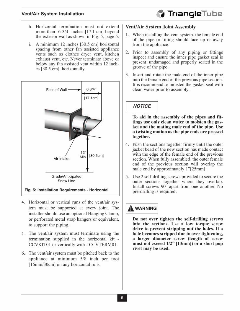
h. Horizontal termination must not extendmore than 6-3/4 inches [17.1 cm] beyondthe exterior wall as shown in Fig. 5, page 5.
i. A minimum 12 inches [30.5 cm] horizontalspacing from other fan assisted appliancevents such as clothes dryer vent, kitchenexhaust vent, etc. Never terminate above orbelow any fan assisted vent within 12 inch-es [30.5 cm], horizontally.
4. Horizontal or vertical runs of the vent/air sys-
tem must be supported at every joint. The
installer should use an optional Hanging Clamp,
or perforated metal strap hangers or equivalent,
to support the piping.
5. The vent/air system must terminate using the
termination supplied in the horizontal kit -
CCVKIT01 or vertically with - CCVTERM01.
6. The vent/air system must be pitched back to the
appliance at minimum 5/8 inch per foot
[16mm/30cm] on any horizontal runs.
6 3/4”
[17.1cm]
[30.5cm]
Face of Wall
12”Min.
Grade/AnticipatedSnow Line
Air Intake
Fig. 5: Installation Requirements - Horizontal
Vent/Air System Installation
6
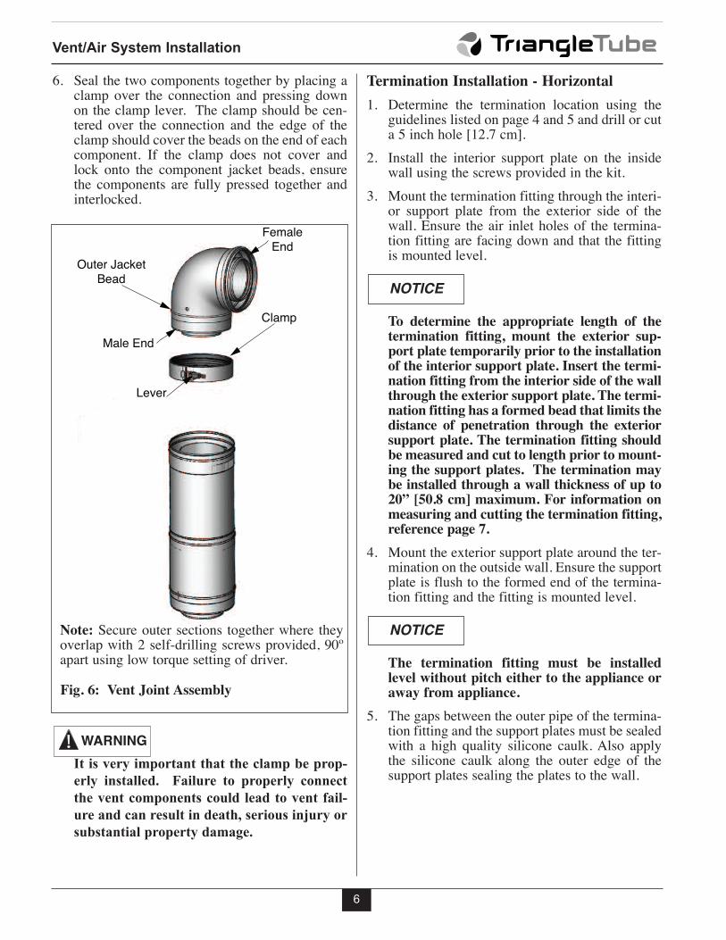
6. Seal the two components together by placing aclamp over the connection and pressing downon the clamp lever. The clamp should be cen-tered over the connection and the edge of theclamp should cover the beads on the end of eachcomponent. If the clamp does not cover andlock onto the component jacket beads, ensurethe components are fully pressed together andinterlocked.
It is very important that the clamp be prop-
erly installed. Failure to properly connect
the vent components could lead to vent fail-
ure and can result in death, serious injury or
substantial property damage.
WARNING
Termination Installation - Horizontal
1. Determine the termination location using theguidelines listed on page 4 and 5 and drill or cuta 5 inch hole [12.7 cm].
2. Install the interior support plate on the insidewall using the screws provided in the kit.
3. Mount the termination fitting through the interi-or support plate from the exterior side of thewall. Ensure the air inlet holes of the termina-tion fitting are facing down and that the fittingis mounted level.
To determine the appropriate length of thetermination fitting, mount the exterior sup-port plate temporarily prior to the installationof the interior support plate. Insert the termi-nation fitting from the interior side of the wallthrough the exterior support plate. The termi-nation fitting has a formed bead that limits thedistance of penetration through the exteriorsupport plate. The termination fitting shouldbe measured and cut to length prior to mount-ing the support plates. The termination maybe installed through a wall thickness of up to20” [50.8 cm] maximum. For information onmeasuring and cutting the termination fitting,reference page 7.
4. Mount the exterior support plate around the ter-mination on the outside wall. Ensure the supportplate is flush to the formed end of the termina-tion fitting and the fitting is mounted level.
The termination fitting must be installedlevel without pitch either to the appliance oraway from appliance.
5. The gaps between the outer pipe of the termina-tion fitting and the support plates must be sealedwith a high quality silicone caulk. Also applythe silicone caulk along the outer edge of thesupport plates sealing the plates to the wall.
NOTICE
NOTICE
Clamp
FemaleEnd
Male End
Outer JacketBead
Lever
Fig. 6: Vent Joint Assembly
Note: Secure outer sections together where theyoverlap with 2 self-drilling screws provided, 90ºapart using low torque setting of driver.
Vent/Air System Installation
7
Termination Installation - Vertical
When venting vertically do not order theConcentric Vent/Air Horizontal Kit - CCVK-IT01 as shown in Fig. 1, order required partsseparately only from listed parts in Fig. 3.
When using an inoperative chimney as ameans of a chase for the vent/air piping thesurrounding space within the chimney can-not be used to draw combustion air or ventanother appliance.
A gas vent extending through a roof shouldnot terminate near an adjacent wall or belowany building extensions such as roof eaves,balconies or decks. Failure to comply withthe required clerances in this manual couldresult in severe personal injury, death or sub-stantial property damage.
1. Determine the termination location using the
guidelines listed on page 4 and 5 and drill or cut
a 5 inch [12.7 cm] hole.
2. Secure appropriately pitched flashing as listed
in Fig. 3.
3. Seal flashing to roof with appropriate sealant
(field supplied).
To determine the appropriate length of thetermination fitting, temporarily mount thevertical termination - CCVTERM01 onto theroof flashing. The termination fitting shouldbe measured and cut to length prior to secur-ing termiantion to flashing. The terminationmaybe installed through a wall thickness ofup to 20” [50.8 cm] maximum.
NOTICE
NOTICE
WARNING
NOTICE
4. Secure and support vertical termination to flash-
ing with included hardware.
5. Seal all exterior joints including pivot points
with silicone sealant.
Cutting Termination Fitting or CCVPIP04 to
Length
1. Only the termination fitting and CCVPIP04 can
be cut to length if required.
Components that may be cut will have a labelon the male end of the part stating “CAN BECUT THIS END ONLY”
2. Add 3/4” [19 mm] to the required length and
mark the end of the outer pipe.
Make sure to add 3/4” [19 mm] to the overallrequired length when cutting both inner andouter pipes.
3. Cut the pipes using an abrasive cutoff saw or
hacksaw (minimum 32 teeth per inch). Make
sure that the inner pipe remains centered in the
outer pipe while cutting. It may be helpful to
temporarily connect the vent section to be cut
into another vent pipe to keep the center pipe
centered while cutting.
4. Mark the end of the outer pipe at the required
length. The length of the outer pipe should be
3/4” [19 mm] less than the inner pipe.
5. Cut through the outer pipe ONLY using a hack-
saw (minimum 32 teeth per inch), or snips.
6. File off any burrs or rough edges on both pipes.
Clean off any dust or dirt.
7. If the cutting process distorted the roundness of
the pipes, carefully use your thumbs to correct
the distortion.
NOTICE
NOTICE
Vent/Air System Installation
8
When cutting or correcting the shape of theouter pipe, WEAR GLOVES. The ends of thevent pipes can become very sharp when cut.
Adjustable Length Vent/Air System Pipe
The component piping and fittings (exclud-ing the termination fittings and CCVPIP04)are not design to be cut for custom lengths.Cutting the piping or fittings to length maycompromise the vent seal causing potentialvent failure or leakage of flue gas resulting indeath, serious injury or substantial injury.
1. An adjustable straight vent/air system pipelength is available for applications that requirecustom lengths.
2. The adjustable length vent/air system pipe isadjustable from a minimum of 12” [30.5 cm] upto a maximum of 16.5” [41.9 cm].
3. To adjust the length, firmly grab each end of thepipe and twist together to shorten or twist apartto lengthen.
WARNING
WARNINGFire Stop Support Plate
The Fire Stop Support Plate must be used when thevent/air system piping passes through any floors, ceil-ings, enclosed chase or exterior walls. This plate canbe used for vertical or horizontal penetrations.
1. Prepare a 5-inch [12.7 cm] round or square open-ing. Remove any insulation from the opening.
2. Secure the plate at the corners using thescrews provided. For exterior wall penetra-tions, 2 plates are required, one on each sideof exterior wall. For interior wall/floor pen-etrations, 1 plate is required.
3. Install the concentric pipe through the plate.Secure the pipe to the Fire Stop Support Plateusing only the self-drilling screws provided,through the plate tabs and into the concentricpipes outer jacket.
The Support Plate provided in the ConcentricVent/Air System Kit does not contain tabs forsecuring the pipe to the plate, where as theFire Stop Support Plate does.
4. Seal around the support plate whereattached to exterior of building and aroundpipe penetration, through the support plateswith silicone sealant.
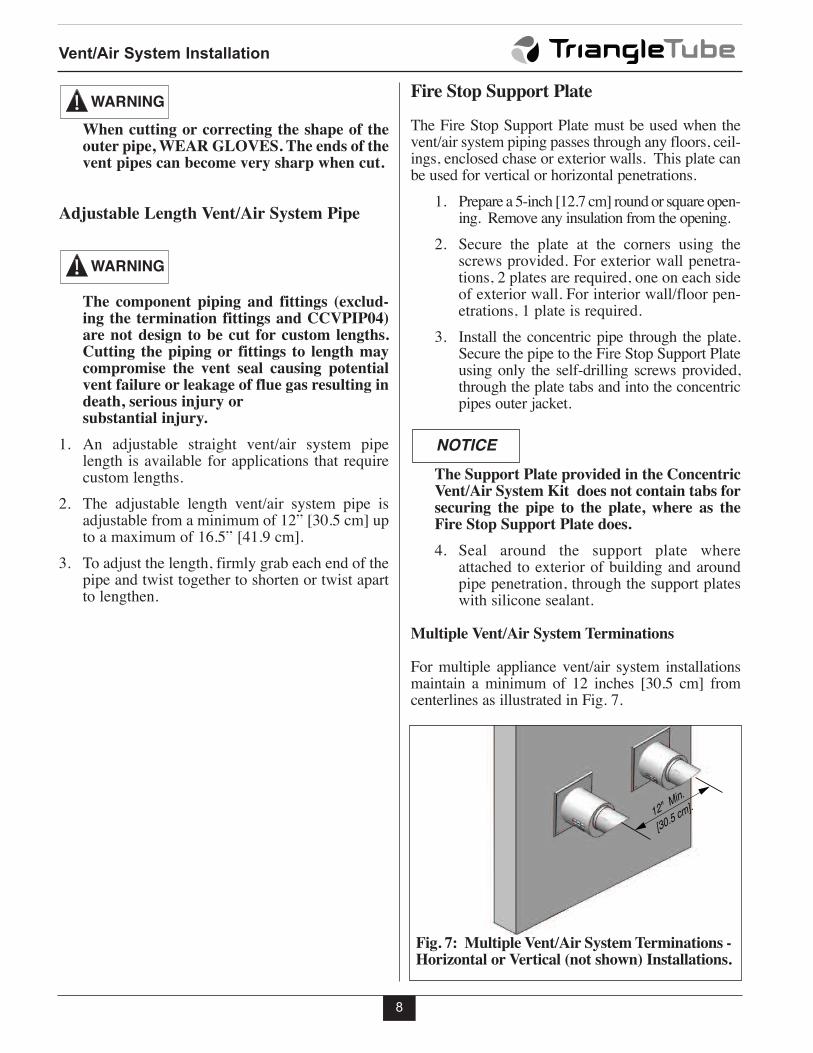
Multiple Vent/Air System Terminations
For multiple appliance vent/air system installationsmaintain a minimum of 12 inches [30.5 cm] fromcenterlines as illustrated in Fig. 7.
NOTICE
12" Min.
[30.5 cm].
Fig. 7: Multiple Vent/Air System Terminations -Horizontal or Vertical (not shown) Installations.
Maintenance Procedures
9
SECTION III - Maintenance Procedures
Inspect Vent/Air System
Visually inspect the vent/air system annually forblockage, deterioration or leakage. Immediatelyrepair any joints that show signs of deterioration orleakage with the appliance turned off.
Failure to inspect the vent/air system andhave any conditions repaired can result insevere personal injury or death.
WARNING
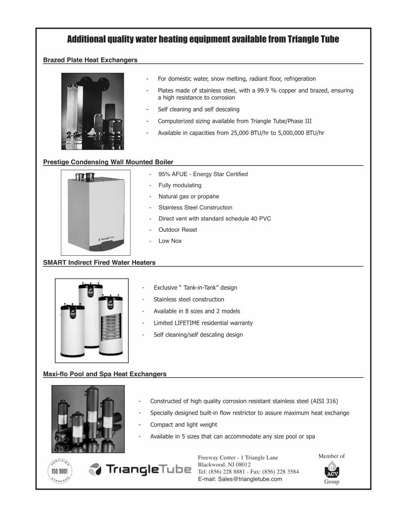
Additional quality water heating equipment available from Triangle Tube
Brazed Plate Heat Exchangers
Prestige Condensing Wall Mounted Boiler
SMART Indirect Fired Water Heaters
Maxi-flo Pool and Spa Heat Exchangers
Freeway Center - 1 Triangle Lane
Blackwood, NJ 08012
Tel: (856) 228 8881 - Fax: (856) 228 3584
E-mail: [email protected]
Member of
Group
- Constructed of high quality corrosion resistant stainless steel (AISI 316)
- Specially designed built-in flow restrictor to assure maximum heat exchange
- Compact and light weight
- Available in 5 sizes that can accommodate any size pool or spa
- For domestic water, snow melting, radiant floor, refrigeration
- Plates made of stainless steel, with a 99.9 % copper and brazed, ensuring
a high resistance to corrosion
- Self cleaning and self descaling
- Computerized sizing available from Triangle Tube/Phase III
- Available in capacities from 25,000 BTU/hr to 5,000,000 BTU/hr
- 95% AFUE - Energy Star Certified
- Fully modulating
- Natural gas or propane
- Stainless Steel Construction
- Direct vent with standard schedule 40 PVC
- Outdoor Reset
- Low Nox
- Exclusive “ Tank-in-Tank” design
- Stainless steel construction
- Available in 8 sizes and 2 models
- Limited LIFETIME residential warranty
- Self cleaning/self descaling design