Embed Size (px)
Citation preview
WARNING
2004-47 Prestige Concentric Vent/Air Term.
This document is intended to be used by a qualified heating contractor or servicetechnician. Read all instructions within this document and within the PRESTIGEBoiler Installation and Maintenance Manual, before proceeding with the installa-tion. It is recommended to follow the procedures in the steps given, skipping ormissing procedural steps could result in severe personal injury, death or sub-stantial property damage.
Installation of this boiler must comply with local requirements and codes andwith the National Fuel Gas Code NFPA 54, ANSI Z223.1 for installations within theU.S. For installations in Canada the installation must comply with CSA B149.1 orB149.2
NOTICE
prestigeConcentric Vent/Air Supplement
2Revised 12/2/05
Table of Contents
i
PRODUCT AND SAFETY INFORMATION
Definitions . . . . . . . . . . . . . . . . . . . . . . . . . . . . . . . . . . . . . . . . . . . . . . . . . . . . . . . . 1Installer Information . . . . . . . . . . . . . . . . . . . . . . . . . . . . . . . . . . . . . . . . . . . . . . . . 1Homeowner Information . . . . . . . . . . . . . . . . . . . . . . . . . . . . . . . . . . . . . . . . . . . . . 1
SECTION I - PRE-INSTALLATION ITEMS
Removal of an Existing Boiler from a Common Vent System . . . . . . . . . . . . . . . . 2Vent/Combustion Air Piping and Materials . . . . . . . . . . . . . . . . . . . . . . . . . . . . . . . 3Combustion Air Contamination . . . . . . . . . . . . . . . . . . . . . . . . . . . . . . . . . . . . . . . . 4
SECTION II - INSTALLING VENT TERMINATION KIT
Vertical - Thru the Roof. . . . . . . . . . . . . . . . . . . . . . . . . . . . . . . . . . . . . . . . . . . . . . 5Determine Termination Location . . . . . . . . . . . . . . . . . . . . . . . . . . . . . . . . . . . . . . . 5-6Vent Installation - Thru the Roof . . . . . . . . . . . . . . . . . . . . . . . . . . . . . . . . . . . . . . . 6Termination Assembly Support . . . . . . . . . . . . . . . . . . . . . . . . . . . . . . . . . . . . . . . . 6Multiple Installation - Thru the Roof . . . . . . . . . . . . . . . . . . . . . . . . . . . . . . . . . . . . 7Horizontal - Sidewall . . . . . . . . . . . . . . . . . . . . . . . . . . . . . . . . . . . . . . . . . . . . . . . . 8Determine Termination Location . . . . . . . . . . . . . . . . . . . . . . . . . . . . . . . . . . . . . . . 8-9Vent Installation - Sidewall . . . . . . . . . . . . . . . . . . . . . . . . . . . . . . . . . . . . . . . . . . . 9Termination Assembly Support . . . . . . . . . . . . . . . . . . . . . . . . . . . . . . . . . . . . . . . . 10Multiple Installation - Sidewall. . . . . . . . . . . . . . . . . . . . . . . . . . . . . . . . . . . . . . . . . 10Assembling Termination Components . . . . . . . . . . . . . . . . . . . . . . . . . . . . . . . . . . 113” To 4” Vent Transition. . . . . . . . . . . . . . . . . . . . . . . . . . . . . . . . . . . . . . . . . . . . . . 12Insert Piping to PRESTIGE Adapters . . . . . . . . . . . . . . . . . . . . . . . . . . . . . . . . . . . 12Vent and Combustion Air Piping Installation Guidelines. . . . . . . . . . . . . . . . . . . . . 12-13
Product and Safety Information
INSTALLER
Read all instructions as outlined in this manualand in the boiler installation manual. Failure tocomply with these instructions in the order pre-sented could result in personal injury or death.
This document is a supplement to the PRESTIGE boil-er installation and maintenance manual and ventingsupplement manual. The purpose of this supplementis for the proper installation of the concentric vent kit tothe boiler.
All vent and combustion air piping must beinstalled, terminated and joints sealed as outlinedin this manual and/or in the venting supplement.Failure to comply with installation procedures out-lined in this manual can result in severe personalinjury, death or substantial property damage.
HOMEOWNER
• This manual is intended for use by a qualified heat-ing contractor or service technician.
• Please reference the User Information manual foradditional information.
• Ensure this document and all pertaining docu-ments are maintained near the boiler to be used bythe qualified heating contractor or service techni-cian.
WARNING
WARNING
1
The following terms are used throughout this manual tobring attention to the presence of potential hazards or toimportant information concerning the product.
Indicates the presence of a hazardous situationwhich, if ignored, will result in death, serious injuryor substantial property damage.
Indicates a potentially hazardous situation which, ifignored, can result in death, serious injury or sub-stantial property damage.
Indicates a potentially hazardous situation which, ifignored, may result in minor injury or substantialproperty damage.
Indicates special instructions on installation, opera-tion or maintenance, which are important to theequipment but not related to personal injury hazards.
Indicates recommendations made by Triangle Tubefor the installers which will help to ensure optimumoperation and longevity of the equipment.
BEST PRACTICES
NOTICE
CAUTION
WARNING
DANGER
DEFINITIONS
Pre-Installation Items
2
SECTION I - PRE- INSTALLATION ITEMS
Removal of an Existing Boiler from a Common VentSystem
Do not install the PRESTIGE into a common ventwith any other gas or oil appliances. This will causeflue gas spillage or appliance malfunction, resultingin possible severe personal injury, death or sub-stantial property damage.
When an existing boiler is removed from a commonventing system, the common venting system is likely tobe too large for proper venting of the remaining appli-ances. At the time of removal of an existing boiler, thefollowing steps shall be followed with each appliancethat remains connected to the common venting system.Place each appliance in operation, while the other appli-ances remaining connected to the common venting sys-tem are not in operation.
1. Seal any unused openings in the common ventingsystem.
2. Visually inspect the venting system for proper sizeand horizontal pitch and determine there is noblockage or restriction, leakage, corrosion and otherdeficiencies which could cause an unsafe condition.
3. Insofar as is practical, close all building doors andwindows and all doors between the space in whichthe appliances remaining connected to the commonventing system are located and other spaces of thebuilding. Turn on clothes dryers and any appliancenot connected to the common venting system. Turnon any exhaust fans, such as range hoods andbathroom exhausts, so they will operate at maxi-mum speed. Do not operate a summer exhaust fan.Close fireplace dampers.
DANGER
4. Place in operation the appliance being inspected.Follow the lighting instructions. Adjust thermostat soappliance will operate continuously.
5. Test for spillage at the draft hood relief opening after5 minutes of main burner operation. Use the flame ofa match or candle, or smoke from a cigarette, cigaror pipe.
6. After it has been determined that each applianceremaining connected to the common venting systemproperly vents when tested as outlined above, returndoors, windows, exhaust fans, fireplace dampersand any other gas-burning appliance to their previ-ous condition of use.
7. Any improper operation of the common venting sys-tem should be corrected so the installation conformswith the National Fuel Gas Code, ANSIZ223.1/NFPA 54 and/or CAN/CGA B149, InstallationCodes. When resizing any portion of the commonventing system, the common venting system shouldbe resized to approach the minimum size as deter-mined using the appropriate tables in Part 11 of theNational Fuel Gas Code, ANSI Z223.1/NFPA 54and/or CAN/CGA B149, Installation Codes.
Do not install the PRESTIGE into a common ventwith any other gas or oil appliances. This will causeflue gas spillage or appliance malfunction, resultingin possible severe personal injury, death or sub-stantial property damage.
DANGER
3
Pre-Installation Items
Vent/Combustion Air Piping and Materials
Installation of the vent and combustion air pipingmust comply with local codes and requirements andwith the National Fuel Gas Code NFPA 54, ANSIZ223.1 for installations in the U.S. or with CSAB149.1 or B149.2 for installations in Canada.
The PRESTIGE requires a Category IV venting systemwhich is designed for pressurized venting and condensate.
The vent and combustion air materials (piping, fit-tings and cement) must meet the listed require-ments in this manual. Failure to comply with thesematerial requirements could result in severe per-sonal injury, death or substantial property damage.
3” and/or 4” Diameter Vent and Combustion AirPiping and Fittings:
For installation of the concentric vent/air termination kitthe vent and air piping must be PVC material only.
PVC Schedule 40 - ANSI/ASTM D1785
PVC-DWV - ANSI/ASTM D2665
Pipe Cement and PrimerFor assembly of the concentric vent/air termination kitcomponents the vent and air piping as well as fittingsmust use PVC cement only.
PVC - ANSI/ASTM D2564
WARNING
NOTICEFor installations in Canada, all piping, fittings andcement/primer material must comply with CSA orULC certification.
Do not use cellular core pipe for venting or combus-tion air.
DO NOT mix vent components from different ventsystems. Use only PVC piping or fittings with theappropriate primer and cement. Failure to complywith this requirement could cause vent failure result-ing in leakage of flue products into the living spacesurrounding the boiler.
The PRESTIGE is certified per ANSI Z21.13 as aCategory IV or Direct Vent (sealed combustion) appli-ance. The PRESTIGE must be installed with the com-bustion air piped directly from outdoors to the unit asdescribed in this supplement.
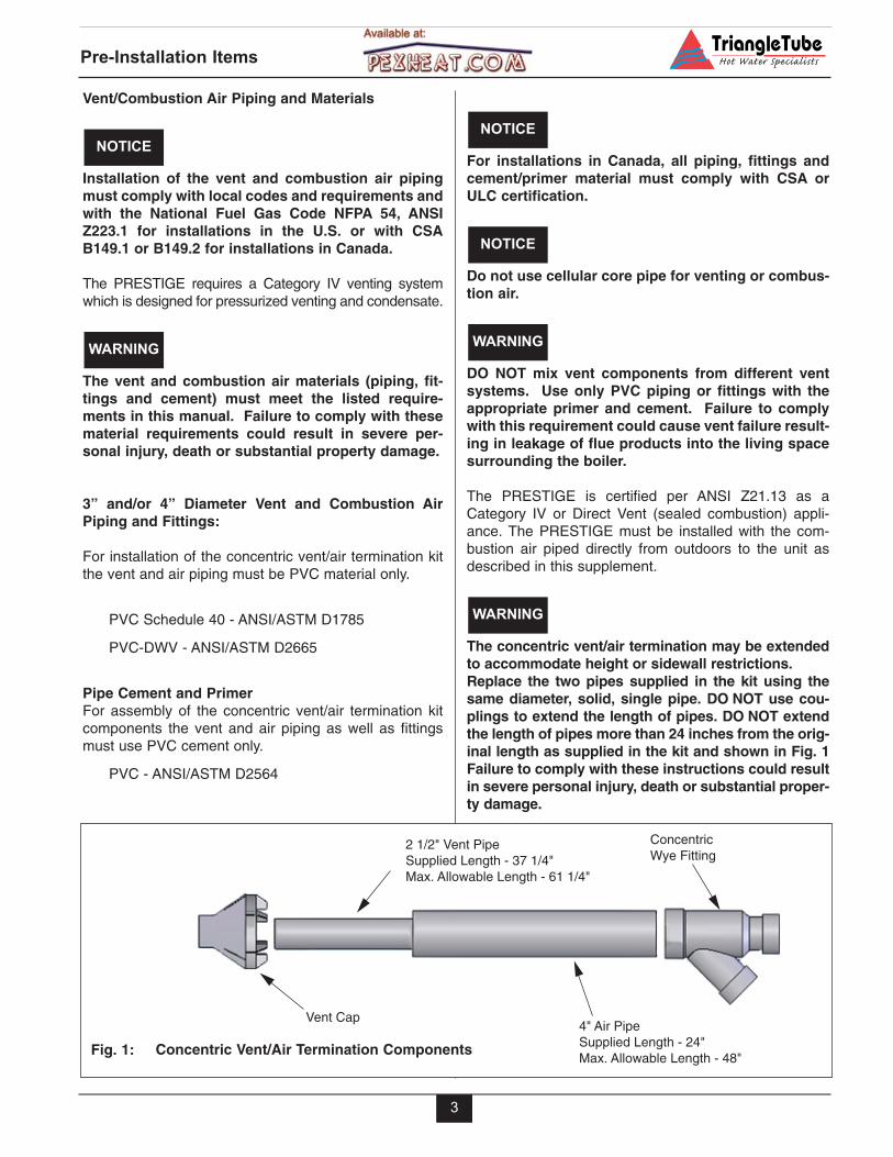
The concentric vent/air termination may be extendedto accommodate height or sidewall restrictions.Replace the two pipes supplied in the kit using thesame diameter, solid, single pipe. DO NOT use cou-plings to extend the length of pipes. DO NOT extendthe length of pipes more than 24 inches from the orig-inal length as supplied in the kit and shown in Fig. 1Failure to comply with these instructions could resultin severe personal injury, death or substantial proper-ty damage.
WARNING
WARNING
NOTICE
NOTICE
Vent Cap
2 1/2" Vent PipeSupplied Length - 37 1/4" Max. Allowable Length - 61 1/4"
ConcentricWye Fitting
4" Air Pipe Supplied Length - 24"Max. Allowable Length - 48"
Concentric Vent/Air Termination ComponentsFig. 1:
Pre-Installation Items
4
Combustion Air Contamination
On a concentrically vented PRESTIGE the com-bustion air must be piped directly from the out-doors to the boiler. If the combustion air inlet islocated in any area likely to cause or contain con-tamination, or if products, which would contami-nate the air cannot be removed, the combustionair must be repiped and terminated to anotherlocation. Contaminated combustion air will dam-age the unit and its burner system, resulting inpossible severe personal injury, death or sub-stantial property damage.
Do not operate a PRESTIGE if its combustion airinlet is located near a laundry room or pool facil-ity. These areas will always contain hazardouscontaminants.
Pool and laundry products, common householdand hobby products often contain fluorine orchlorine compounds. When these chemicalspass through the burner and vent system, theycan form strong acids. These acids can createcorrosion of the heat exchanger, burner compo-nents and vent system, causing serious damageand presenting a possible threat of flue gasspillage or water leakage into the surroundingarea.
Please read the information listed below. If con-taminating chemicals are located near the areaof the combustion air inlet, the installer shouldpipe the combustion air inlet to an area free ofthese chemicals.
DANGER
WARNING
Potential contaminating products
- Spray cans containing chloro/fluorocarbons
- Permanent Wave Solutions
- Chlorinated wax
- Chlorine - based swimming pool chemicals /cleaners
- Calcium Chloride used for thawing ice
- Sodium Chloride used for water softening
- Refrigerant leaks
- Paint or varnish removers
- Hydrochloric acid / muriatic acid
- Cements and glues
- Antistatic fabric softeners used in clothe dryers
- Chlorine-type bleaches, detergents, and clean-ing solvents found in household laundry rooms
- Adhesives used to fasten building products andother similar products
Areas likely to contain these products
- Dry cleaning / laundry areas and establishments
- Beauty salons
- Metal fabrication shops
- Swimming pools and health spas
- Refrigeration Repair shops
- Photo processing plants
- Auto body shops
- Plastic manufacturing plants
- Furniture refinishing areas and establishments
- New building construction
- Remodeling areas
- Garages with workshops
Installing Vent Termination Kit
5
SECTION II - INSTALLING VENT TERMINATION KIT
Vertical - Thru the Roof
Installation of the vent and combustion air pipingmust comply with local codes and requirements andwith the National Fuel Gas Code NFPA 54, ANSIZ223.1 for installations in the U.S. or CSA B149.1 orB149.2 for installations in Canada.
A gas vent extending through a roof should not ter-minate near an adjacent wall or below any buildingextensions such as roof eaves, balconies or decks.Failure to comply with the required clearances couldresult in severe personal injury, death or substantialproperty damage.
Determine Termination Location
Locate the vent and combustion air termination using thefollowing guidelines:
1. The total length of the vent or combustion air pipingmust not exceed the limits given in Table 1 on page 13.
Include the two concentric vent/air termination pip-ing length when determining the total length of pipe.
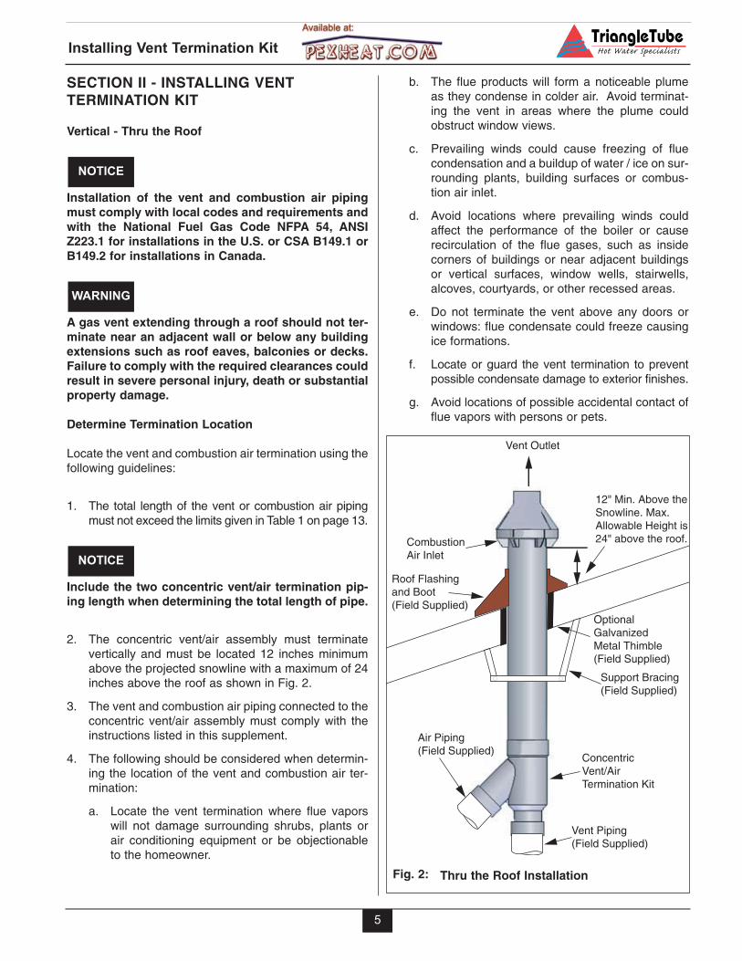
2. The concentric vent/air assembly must terminatevertically and must be located 12 inches minimumabove the projected snowline with a maximum of 24inches above the roof as shown in Fig. 2.
3. The vent and combustion air piping connected to theconcentric vent/air assembly must comply with theinstructions listed in this supplement.
4. The following should be considered when determin-ing the location of the vent and combustion air ter-mination:
a. Locate the vent termination where flue vaporswill not damage surrounding shrubs, plants orair conditioning equipment or be objectionableto the homeowner.
NOTICE
WARNING
NOTICE
b. The flue products will form a noticeable plumeas they condense in colder air. Avoid terminat-ing the vent in areas where the plume couldobstruct window views.
c. Prevailing winds could cause freezing of fluecondensation and a buildup of water / ice on sur-rounding plants, building surfaces or combus-tion air inlet.
d. Avoid locations where prevailing winds couldaffect the performance of the boiler or causerecirculation of the flue gases, such as insidecorners of buildings or near adjacent buildingsor vertical surfaces, window wells, stairwells,alcoves, courtyards, or other recessed areas.
e. Do not terminate the vent above any doors orwindows: flue condensate could freeze causingice formations.
f. Locate or guard the vent termination to preventpossible condensate damage to exterior finishes.
g. Avoid locations of possible accidental contact offlue vapors with persons or pets.
Vent Piping(Field Supplied)
Air Piping(Field Supplied)
Concentric Vent/AirTermination Kit
Support Bracing(Field Supplied)
OptionalGalvanized Metal Thimble(Field Supplied)
Roof Flashingand Boot(Field Supplied)
CombustionAir Inlet
Vent Outlet
12" Min. Above the Snowline. Max. Allowable Height is24" above the roof.
Thru the Roof InstallationFig. 2:
Installing Vent Termination Kit
6
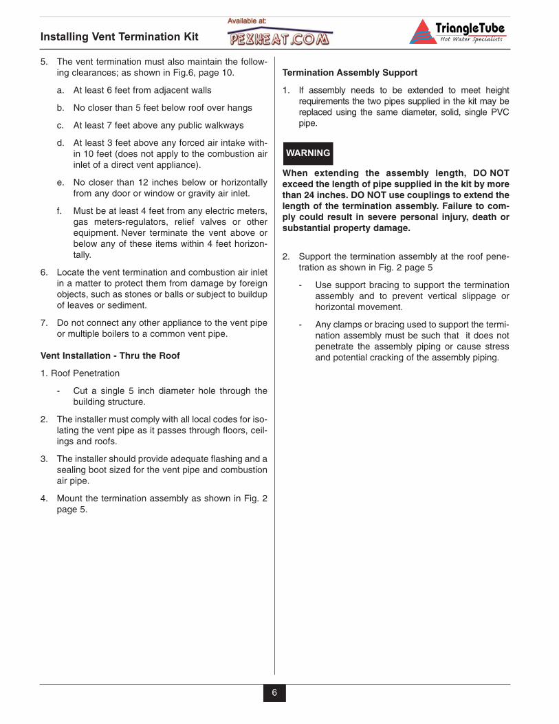
5. The vent termination must also maintain the follow-ing clearances; as shown in Fig.6, page 10.
a. At least 6 feet from adjacent walls
b. No closer than 5 feet below roof over hangs
c. At least 7 feet above any public walkways
d. At least 3 feet above any forced air intake with-in 10 feet (does not apply to the combustion airinlet of a direct vent appliance).
e. No closer than 12 inches below or horizontallyfrom any door or window or gravity air inlet.
f. Must be at least 4 feet from any electric meters,gas meters-regulators, relief valves or otherequipment. Never terminate the vent above orbelow any of these items within 4 feet horizon-tally.
6. Locate the vent termination and combustion air inletin a matter to protect them from damage by foreignobjects, such as stones or balls or subject to buildupof leaves or sediment.
7. Do not connect any other appliance to the vent pipeor multiple boilers to a common vent pipe.
Vent Installation - Thru the Roof
1. Roof Penetration
- Cut a single 5 inch diameter hole through thebuilding structure.
2. The installer must comply with all local codes for iso-lating the vent pipe as it passes through floors, ceil-ings and roofs.
3. The installer should provide adequate flashing and asealing boot sized for the vent pipe and combustionair pipe.
4. Mount the termination assembly as shown in Fig. 2page 5.
Termination Assembly Support
1. If assembly needs to be extended to meet heightrequirements the two pipes supplied in the kit may bereplaced using the same diameter, solid, single PVCpipe.
When extending the assembly length, DO NOTexceed the length of pipe supplied in the kit by morethan 24 inches. DO NOT use couplings to extend thelength of the termination assembly. Failure to com-ply could result in severe personal injury, death orsubstantial property damage.
2. Support the termination assembly at the roof pene-tration as shown in Fig. 2 page 5
- Use support bracing to support the terminationassembly and to prevent vertical slippage orhorizontal movement.
- Any clamps or bracing used to support the termi-nation assembly must be such that it does notpenetrate the assembly piping or cause stressand potential cracking of the assembly piping.
WARNING
All vent outlets of the termination assemblies mustbe of the same height to avoid flue gas recirculationand the possibility of severe personal injury, deathor substantial property damage.
The combustion air inlet of the PRESTIGE is definedas being part of a direct vent system. It is not con-sidered as a forced air intake. The required clear-ance of an adjacent boiler vent to a forced air inletdoes not apply in a multiple installation of PRES-TIGE boilers.
NOTICE
WARNING
Installing Vent Termination Kit
7
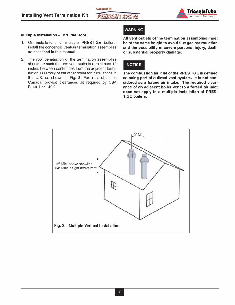
Multiple Installation - Thru the Roof
1. On installations of multiple PRESTIGE boilers,install the concentric vent/air termination assembliesas described in this manual.
2. The roof penetration of the termination assembliesshould be such that the vent outlet is a minimum 12inches between centerlines from the adjacent termi-nation assembly of the other boiler for installations inthe U.S. as shown in Fig. 3. For installations inCanada, provide clearances as required by CSAB149.1 or 149.2.
12" Min. above snowline24" Max. height above roof
12" Min.
Multiple Vertical InstallationFig. 3:
Installing Vent Termination Kit
8
Horizontal - Sidewall
Installation of the vent and combustion air pipingmust comply with local codes and requirements andwith the National Fuel Gas Code NFPA 54, ANSIZ223.1 for installations in the U.S. or CSA B149.1 orB149.2 for installations in Canada.
A gas vent extending through a sidewall should notterminate near an adjacent wall or below any build-ing extensions such as roof eaves, balconies ordecks. Failure to comply with the required clear-ances could result in severe personal injury, deathor substantial property damage.
Determine Termination Location
Locate the vent and combustion air termination using thefollowing guidelines:
1. The total length of the vent or combustion air pipingmust not exceed the limits given in Table 1 on page 13.
2. The concentric vent/air termination assembly mustbe installed 12 inches above grade or projectedsnowline as shown in Fig. 4
WARNING
NOTICE
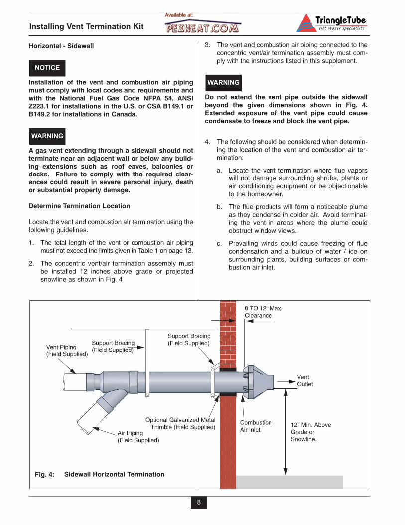
3. The vent and combustion air piping connected to theconcentric vent/air termination assembly must com-ply with the instructions listed in this supplement.
Do not extend the vent pipe outside the sidewallbeyond the given dimensions shown in Fig. 4.Extended exposure of the vent pipe could causecondensate to freeze and block the vent pipe.
4. The following should be considered when determin-ing the location of the vent and combustion air ter-mination:
a. Locate the vent termination where flue vaporswill not damage surrounding shrubs, plants orair conditioning equipment or be objectionableto the homeowner.
b. The flue products will form a noticeable plumeas they condense in colder air. Avoid terminat-ing the vent in areas where the plume couldobstruct window views.
c. Prevailing winds could cause freezing of fluecondensation and a buildup of water / ice onsurrounding plants, building surfaces or com-bustion air inlet.
WARNING
Air Piping(Field Supplied)
Optional Galvanized MetalThimble (Field Supplied) 12" Min. Above
Grade or Snowline.
VentOutlet
0 TO 12" Max.Clearance
Support Bracing(Field Supplied)Support Bracing
(Field Supplied)Vent Piping(Field Supplied)
CombustionAir Inlet
Sidewall Horizontal TerminationFig. 4:
9
d. Avoid locations where prevailing winds couldaffect the performance of the boiler or causerecirculation of the flue gases, such as insidecorners of buildings or near adjacent buildingsor vertical surfaces, window wells, stairwells,alcoves, courtyards, or other recessed areas.
e. Do not terminate the vent above any doors orwindows: flue condensate could freeze causingice formations.
f. Locate or guard the vent termination to preventpossible condensate damage to exterior finishes.
g. Avoid locations of possible accidental contact offlue vapors with persons or pets.
5. The vent termination must also maintain the follow-ing clearances; as shown in Fig.6, page 10.
a. At least 6 feet from adjacent walls
b. No closer than 5 feet below roof overhangs
c. At least 7 feet above any public walkways
d. At least 3 feet above any forced air intake with-in 10 feet (does not apply to the combustion airinlet of a direct vent appliance).
e. No closer than 12 inches below or horizontallyfrom any door or window or gravity air inlet.
f. Must be at least 4 feet from any electric meters,gas meters-regulators, relief valves or otherequipment. Never terminate the vent above orbelow any of these items within 4 feet horizon-tally.
g. A maximum of 12 inches beyond the exteriorwall.
6. Locate the vent termination and combustion air inletin a matter to protect from damage by foreignobjects, such as stones or balls or subject to buildupof leaves or sediment.
7. Do not connect any other appliance to the vent pipeor multiple boilers to a common vent pipe.
Vent Installation - Sidewall
1. Sidewall Penetration
- Cut a single 5 inch diameter hole through thebuilding structure.
2. The installer must comply with all local codes for iso-lating the vent pipe as it passes through floors andwalls.
3. The installer should seal all exterior openings withan exterior silicon caulk.
Installing Vent Termination Kit
Termination Assembly Support
1. If assembly needs to be extended to meet wall thick-ness requirements the two pipes supplied in the kit maybe replaced using the same diameter, solid, single PVCpipe.
When extending the assembly length, DO NOTexceed the length of pipe supplied in the kit by morethan 24 inches. DO NOT use couplings to extend thelength of the termination assembly. Failure to com-ply could result in severe personal injury, death orsubstantial property damage.
2. Support the termination assembly at the wall pene-tration as shown in Fig. 4.
- Use support bracing to support the terminationassembly and to prevent horizontal slippage orvertical movement.
- Any clamps or bracing used to support the ter-mination assembly must be such that it does notpenetrate the assembly piping or cause stressand potential cracking of the assembly piping.
WARNING
Installing Vent Termination Kit
10
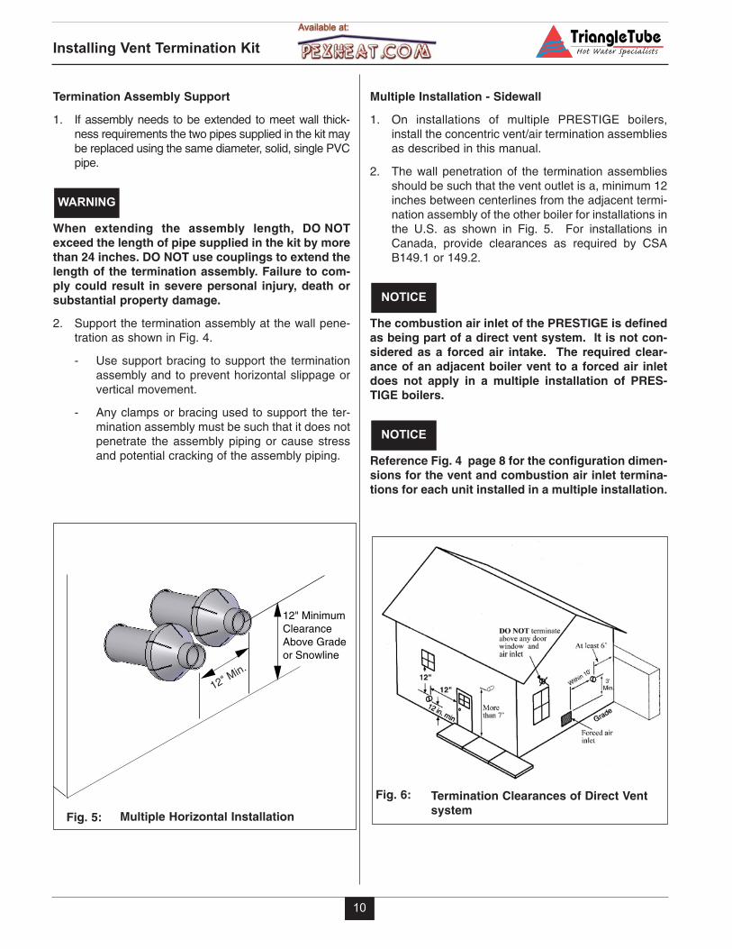
Multiple Installation - Sidewall
1. On installations of multiple PRESTIGE boilers,install the concentric vent/air termination assembliesas described in this manual.
2. The wall penetration of the termination assembliesshould be such that the vent outlet is a, minimum 12inches between centerlines from the adjacent termi-nation assembly of the other boiler for installations inthe U.S. as shown in Fig. 5. For installations inCanada, provide clearances as required by CSAB149.1 or 149.2.
The combustion air inlet of the PRESTIGE is definedas being part of a direct vent system. It is not con-sidered as a forced air intake. The required clear-ance of an adjacent boiler vent to a forced air inletdoes not apply in a multiple installation of PRES-TIGE boilers.
Reference Fig. 4 page 8 for the configuration dimen-sions for the vent and combustion air inlet termina-tions for each unit installed in a multiple installation.
NOTICE
NOTICE
12" Min.
12" MinimumClearance Above Gradeor Snowline
Multiple Horizontal InstallationFig. 5:
Termination Clearances of Direct Ventsystem
Fig. 6:
Installing Vent Termination Kit
11
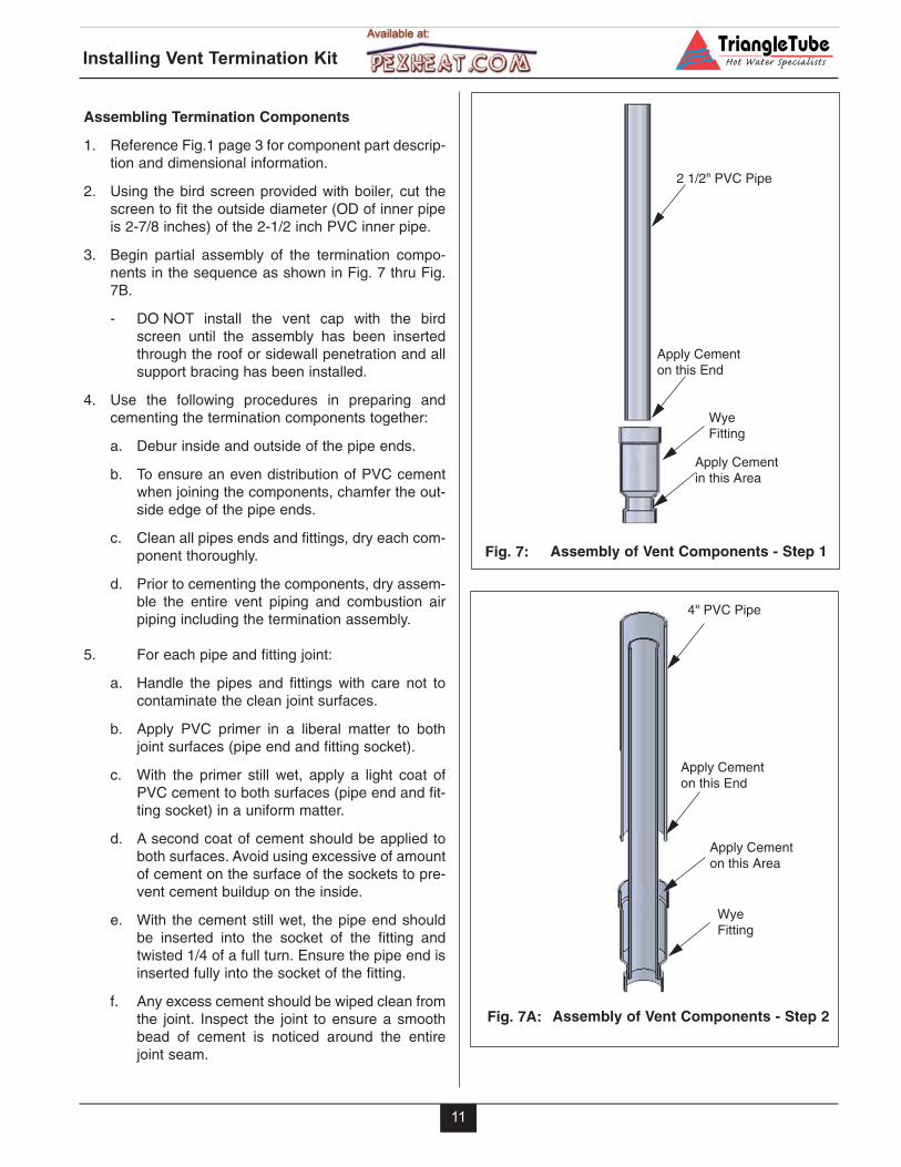
Assembling Termination Components
1. Reference Fig.1 page 3 for component part descrip-tion and dimensional information.
2. Using the bird screen provided with boiler, cut thescreen to fit the outside diameter (OD of inner pipeis 2-7/8 inches) of the 2-1/2 inch PVC inner pipe.
3. Begin partial assembly of the termination compo-nents in the sequence as shown in Fig. 7 thru Fig.7B.
- DO NOT install the vent cap with the birdscreen until the assembly has been insertedthrough the roof or sidewall penetration and allsupport bracing has been installed.
4. Use the following procedures in preparing andcementing the termination components together:
a. Debur inside and outside of the pipe ends.
b. To ensure an even distribution of PVC cementwhen joining the components, chamfer the out-side edge of the pipe ends.
c. Clean all pipes ends and fittings, dry each com-ponent thoroughly.
d. Prior to cementing the components, dry assem-ble the entire vent piping and combustion airpiping including the termination assembly.
5. For each pipe and fitting joint:
a. Handle the pipes and fittings with care not tocontaminate the clean joint surfaces.
b. Apply PVC primer in a liberal matter to bothjoint surfaces (pipe end and fitting socket).
c. With the primer still wet, apply a light coat ofPVC cement to both surfaces (pipe end and fit-ting socket) in a uniform matter.
d. A second coat of cement should be applied toboth surfaces. Avoid using excessive of amountof cement on the surface of the sockets to pre-vent cement buildup on the inside.
e. With the cement still wet, the pipe end shouldbe inserted into the socket of the fitting andtwisted 1/4 of a full turn. Ensure the pipe end isinserted fully into the socket of the fitting.
f. Any excess cement should be wiped clean fromthe joint. Inspect the joint to ensure a smoothbead of cement is noticed around the entirejoint seam.
2 1/2" PVC Pipe
Apply Cementon this End
WyeFitting
Apply Cementin this Area
Assembly of Vent Components - Step 1Fig. 7:
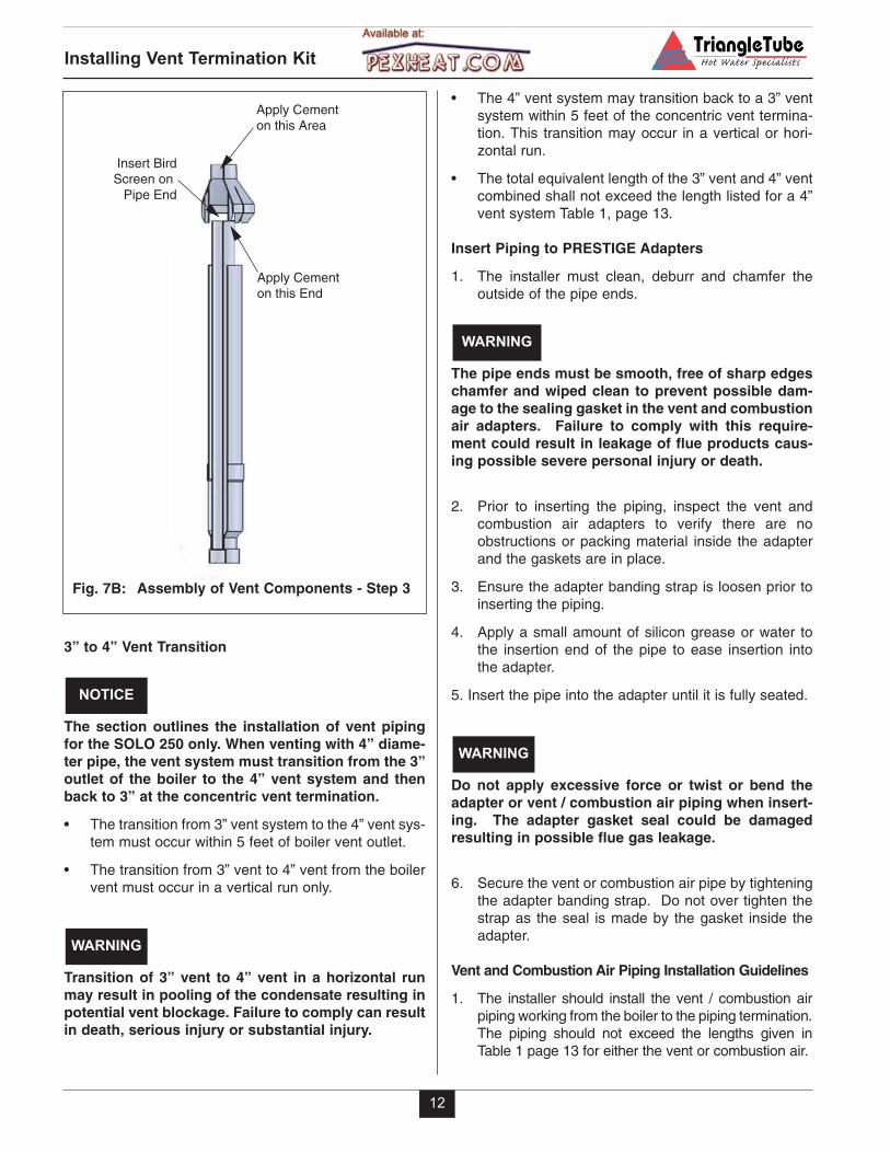
Apply Cementon this End
Apply Cementon this Area
WyeFitting
4" PVC Pipe
Assembly of Vent Components - Step 2Fig. 7A:
12
Installing Vent Termination Kit
• The 4” vent system may transition back to a 3” ventsystem within 5 feet of the concentric vent termina-tion. This transition may occur in a vertical or hori-zontal run.
• The total equivalent length of the 3” vent and 4” ventcombined shall not exceed the length listed for a 4”vent system Table 1, page 13.
Insert Piping to PRESTIGE Adapters
1. The installer must clean, deburr and chamfer theoutside of the pipe ends.
The pipe ends must be smooth, free of sharp edgeschamfer and wiped clean to prevent possible dam-age to the sealing gasket in the vent and combustionair adapters. Failure to comply with this require-ment could result in leakage of flue products caus-ing possible severe personal injury or death.
2. Prior to inserting the piping, inspect the vent andcombustion air adapters to verify there are noobstructions or packing material inside the adapterand the gaskets are in place.
3. Ensure the adapter banding strap is loosen prior toinserting the piping.
4. Apply a small amount of silicon grease or water tothe insertion end of the pipe to ease insertion intothe adapter.
5. Insert the pipe into the adapter until it is fully seated.
Do not apply excessive force or twist or bend theadapter or vent / combustion air piping when insert-ing. The adapter gasket seal could be damagedresulting in possible flue gas leakage.
6. Secure the vent or combustion air pipe by tighteningthe adapter banding strap. Do not over tighten thestrap as the seal is made by the gasket inside theadapter.
Vent and Combustion Air Piping Installation Guidelines
1. The installer should install the vent / combustion airpiping working from the boiler to the piping termination.The piping should not exceed the lengths given inTable 1 page 13 for either the vent or combustion air.
WARNING
WARNING
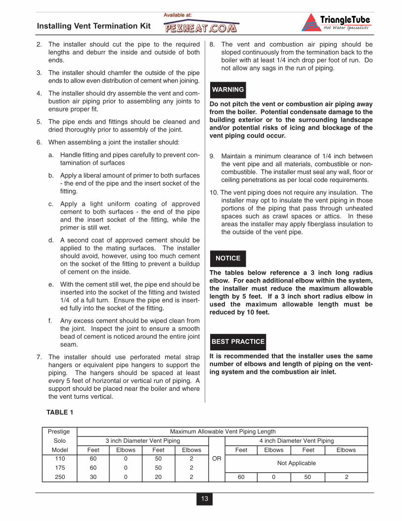
Insert BirdScreen on
Pipe End
Apply Cementon this Area
Apply Cementon this End
Assembly of Vent Components - Step 3Fig. 7B:
3” to 4” Vent Transition
The section outlines the installation of vent pipingfor the SOLO 250 only. When venting with 4” diame-ter pipe, the vent system must transition from the 3”outlet of the boiler to the 4” vent system and thenback to 3” at the concentric vent termination.
• The transition from 3” vent system to the 4” vent sys-tem must occur within 5 feet of boiler vent outlet.
• The transition from 3” vent to 4” vent from the boilervent must occur in a vertical run only.
Transition of 3” vent to 4” vent in a horizontal runmay result in pooling of the condensate resulting inpotential vent blockage. Failure to comply can resultin death, serious injury or substantial injury.
WARNING
NOTICE
13
2. The installer should cut the pipe to the requiredlengths and deburr the inside and outside of bothends.
3. The installer should chamfer the outside of the pipeends to allow even distribution of cement when joining.
4. The installer should dry assemble the vent and com-bustion air piping prior to assembling any joints toensure proper fit.
5. The pipe ends and fittings should be cleaned anddried thoroughly prior to assembly of the joint.
6. When assembling a joint the installer should:
a. Handle fitting and pipes carefully to prevent con-tamination of surfaces
b. Apply a liberal amount of primer to both surfaces- the end of the pipe and the insert socket of thefitting.
c. Apply a light uniform coating of approvedcement to both surfaces - the end of the pipeand the insert socket of the fitting, while theprimer is still wet.
d. A second coat of approved cement should beapplied to the mating surfaces. The installershould avoid, however, using too much cementon the socket of the fitting to prevent a buildupof cement on the inside.
e. With the cement still wet, the pipe end should beinserted into the socket of the fitting and twisted1/4 of a full turn. Ensure the pipe end is insert-ed fully into the socket of the fitting.
f. Any excess cement should be wiped clean fromthe joint. Inspect the joint to ensure a smoothbead of cement is noticed around the entire jointseam.
7. The installer should use perforated metal straphangers or equivalent pipe hangers to support thepiping. The hangers should be spaced at leastevery 5 feet of horizontal or vertical run of piping. Asupport should be placed near the boiler and wherethe vent turns vertical.
8. The vent and combustion air piping should besloped continuously from the termination back to theboiler with at least 1/4 inch drop per foot of run. Donot allow any sags in the run of piping.
Do not pitch the vent or combustion air piping awayfrom the boiler. Potential condensate damage to thebuilding exterior or to the surrounding landscapeand/or potential risks of icing and blockage of thevent piping could occur.
9. Maintain a minimum clearance of 1/4 inch betweenthe vent pipe and all materials, combustible or non-combustible. The installer must seal any wall, floor orceiling penetrations as per local code requirements.
10. The vent piping does not require any insulation. Theinstaller may opt to insulate the vent piping in thoseportions of the piping that pass through unheatedspaces such as crawl spaces or attics. In theseareas the installer may apply fiberglass insulation tothe outside of the vent pipe.
The tables below reference a 3 inch long radiuselbow. For each additional elbow within the system,the installer must reduce the maximum allowablelength by 5 feet. If a 3 inch short radius elbow inused the maximum allowable length must bereduced by 10 feet.
It is recommended that the installer uses the samenumber of elbows and length of piping on the vent-ing system and the combustion air inlet.
BEST PRACTICE
NOTICE
WARNING
Installing Vent Termination Kit
TABLE 1
Prestige
Solo
Model Feet Elbows Feet Elbows Feet Elbows Feet Elbows110 60 0 50 2 OR
175 60 0 50 2
250 30 0 20 2 60 0 50 2
Maximum Allowable Vent Piping Length
3 inch Diameter Vent Piping 4 inch Diameter Vent Piping
Not Applicable

Additional quality water heating equipment available fromTriangle Tube/Phase III
PRIMARY / SECONDARY MANIFOLD
PHASE III INDIRECT FIRED WATER HEATERS
TTP BRAZED PLATE HEAT EXCHANGERS
- Exclusive tank-in-tank design
- Stainless steel construction
- Available in 8 sizes and 2 models
- Limited LIFETIME residential warranty
- 15 year limited commercial warranty
- Self cleaning/self descaling design
Freeway Center - 1 Triangle Lane - Blackwood, NJ 08012Tel: (856) 228 8881 - Fax: (856) 228 3584E-mail: [email protected]
- For domestic water, snow melting, radiant floor,refrigeration
- Plates made of stainless steel, with a 99.9 % copperand brazed, ensuring a high resistance to corrosion
- Self cleaning and self descaling
- Computerized sizing available from TriangleTube/Phase III
- Available in capacities from 25,000 BTU/hr to5,000,000 BTU/hr
Member of
Group
- Combination hydronic separator, pressure equalizerand distribution manifold
- Ensures a proper primary/secondary piping arrange-ment for up to three zones
- Easy to install and compact