Embed Size (px)
Citation preview

47518999001Edition 2
October 2017
Save These Instructions
Air Starters for Internal Combustion EngineST150 Series
Maintenance Information
2 47518999001_ed2
Product Safety Information
WARNING
• Failure to observe the following warnings, and to avoid these potentially hazardous situations, could result in death or serious injury. • Read and understand this and all other supplied manuals before installing, operating, repairing, maintaining, changing accessories on, or
working near this product. • Always wear eye protection when operating or performing maintenance on this starter. The grade of protection required should be assessed
for each use and may include impact-resistant glasses with side shields, goggles, or a full face shield over those glasses. • Always turn off the air or gas supply and disconnect the air or gas supply hose before installing; removing or adjusting any accessory; or
before performing any maintenance on this starter.
General Instructions • Reference Parts Information Manual for item number call outs. • Do not disassemble the tool any further than necessary to replace or repair damaged parts. • Always mark alignment between the inlet housing (4), motor housing (15), gear case (40), gear case cover (51, 57, 69, 72), drive housing (82,
102, 109) and flange (103) with a permanent mark that cannot be erased or washed away in order to retain proper orientation. • Always use soft jaws when grasping a part in a vice. Do not tighten vice more than necessary. • Always have a complete set of seals, gaskets, and O-Rings on hand before starting any overhaul. Never reuse old seals, gaskets, or O-Rings. • These steps outline complete disassembly. Do not disassemble the starter any further than necessary to replace a worn or damaged part. • Do not remove any press fit part unless the removal of that part is necessary for replacement or repairs. • Do not reuse any bearing disassembled from a press fit. • Ensure all parts are clean and free of debris or damage before assembly. Replace any damaged parts with genuine Ingersoll Rand replacements. • Lubricate all O-Rings with O-Ring lubricant prior to assembly. • Clean all grease and oils from housings prior to assembly.
Disassembly of Motor Module – All Models
1. Remove hex screws (2) and washers (1) from inlet housing (4).
2. Remove Motor Module by separating motor housing (15) from gear case (40).
3. Remove inlet housing (4) from motor housing (15).
4. Remove rotor (10) assembly from nozzle (6). Do not damage rotor.
5. Remove disc spring (8) from nozzle (6).
6. Remove screws (7) and nozzle (6) from inlet housing (4).
7. Remove O-Ring (5) from inlet housing (4).
8. Press ball bearings (9) and spacer (11) from rotor. Do not damage rotor.
9. Remove ring (12) from motor housing (15).
10. Remove internal retaining ring (23), shim (22), wave spring (21), and shaft (17) assembly from motor housing (15).
11. Press seal (13) from motor housing (15).
12. Remove O-Ring (5) from motor housing (15).
Disassembly of Drive ModuleST15()()H Models
1) Remove hex screws (81) and washers (80) from drive housing (102).
2) Remove Drive Module from Gear Module.
3) Remove pinion bolt (107). Thread direction is opposite of direction of pinion rotation.
4) Remove pinion (106) and collar (105) from shaft (97).
5) Remove screws (104) from flange (103).
6) Remove flange (103) from drive housing (102).
7) Remove piston (86) and shaft (97) assembly from drive housing (102).
8) Remove spring (98) from drive housing (102).
9) Remove needle bearing (99) from drive housing (102).
10) Remove seal (100) from drive housing (102).
11) Remove piston (86) from bearing (90).
12) Remove O-Ring (85) from piston (86).
13) Remove nut (87) and washer (88) from shaft (97) assembly.
14) Remove external retaining ring (89) from clutch jaw (91).
15) Press bearing (90) from clutch jaw (91).
16) Remove internal retaining ring (93) from clutch jaw (91).
17) Remove needle bearing (92) from clutch jaw (91).
18) Remove clutch jaw (94), spring (95) and sleeve (96) from shaft (97).
ST15()()I Models
1) Remove hex screws (81) and washers (80) from drive housing (109).
2) Remove drive (108) from shaft (48 or 65).
3) Press needle bearing (110) from drive housing (109).
ST15()()P Models
1) Remove hex screws (81) and washers (80) from drive housing (82).
2) Remove drive housing (82) from cover (51).
3) Remove piston (77) and drive (76) assembly with spring (79) from shaft (48 or 65).
4) Remove internal retaining ring (73) from piston (77).
5) Remove ring (74) from piston (77).
6) Remove drive (76) from piston (77).
7) Remove shift rings (75) from drive (76).
8) Remove O-Ring (78) from piston (77).
9) Press needle bearing (83) from drive housing (82).
Disassembly of Gear ModuleST15()DI and ST15()DP Models
1) Remove hex screws (2) and washers (1) from inlet housing (4).
2) Remove Motor Module from Gear Module.
3) Remove hex screws (81) and washers (80) from drive housing (82 or 109).
4) Remove Drive Module from Gear Module.
5) Remove cover (69) from gear case (40).
6) Remove external retaining ring (70) from carrier (65).
7) Remove carrier (65) from cover (69).
Disassembly
47518999001_ed2 3
8) Remove O-Ring (52), O-Ring (53), and O-Ring (68) from cover (69).
9) Remove internal retaining ring (66) from cover (69).
10) Remove bearing (67) from cover (69).
11) Press pins (64) from carrier (65) from side opposite spline.
12) Remove planet gears (62) from carrier (65).
13) Remove planetary assembly from gear case (40).
14) Remove bearing (35) seal from gear case (40).
15) Remove O-Ring (38) from gear case (40).
16) Remove external retaining ring (37) from carrier (32).
17) Remove pinion (36) from carrier (32).
18) Press bearing (35) from carrier (32).
19) Remove external retaining ring (34) from carrier (32).
20) Remove planet pins (33) from carrier (32).
21) Remove planet gears (30) and thrust washers (29) from carrier (32).
22) Press bearing (27) from carrier (32).
ST15()DH Models
1) Remove hex screws (2) and washers (1) from inlet housing (4).
2) Remove Motor Module from Gear Module.
3) Remove hex screws (81) and washers (80) from drive housing (102).
4) Remove Drive Module from Gear Module.
5) Remove cover (72) from gear case (40).
6) Pull seal (58) from cover (72).
7) Remove external retaining ring (56) from carrier (71).
8) Remove carrier (71) from cover (72).
9) Remove internal retaining ring (59) from cover (72).
10) Remove bearing (55) from cover (72).
11) Remove O-Ring (60), O-Ring (61), and O-Ring (68) from cover (72).
12) Press pins (64) from carrier (71) from side opposite spline.
13) Remove planet gears (62) from carrier (71).
14) Remove planetary assembly from gear case (40).
15) Remove bearing (35) seal from gear case (40).
16) Remove O-Ring (38) from gear case (40).
17) Remove external retaining ring (37) from carrier (32).
18) Remove pinion (36) from carrier (32).
19) Press bearing (35) from carrier (32).
20) Remove external retaining ring (34) from carrier (32).
21) Remove planet pins (33) from carrier (32).
22) Remove planet gears (30) and thrust washers (29) from carrier (32).
23) Press bearing (27) from carrier (32).
ST15()FI and ST15()FP Models
1) Remove hex screws (2) and washers (1) from inlet housing (4).
2) Remove Motor Module from Gear Module.
3) Remove hex screws (81) and washers (80) from drive housing
(82 or 109).
4) Remove Drive Module from Gear Module.
5) Remove cover (51) from gear case (40).
6) Remove shaft (48) and gear (44) assembly from cover (51).
7) Remove O-Ring (52) and O-Ring (53) from cover (51).
8) Press seal (50) from cover (51).
9) Press gear (44) from shaft (48) and remove key (47).
10) Press bearing (45) from shaft (48).
11) Press collar (46) from shaft (48).
12) Remove gasket (49) from gear case (40).
13) Remove washer (43) from gear case (40).
14) Pull bearing (42) from gear case (40) by threading a 5/16-18 screw into washer (41).
15) Remove planetary assembly from gear case (40).
16) Remove bearing (35) seal from gear case (40).
17) Remove O-Ring (38) from gear case (40).
18) Remove external retaining ring (37) from carrier (32).
19) Remove pinion (36) from carrier (32).
20) Press bearing (35) from carrier (32).
21) Remove external retaining ring (34) from carrier (32).
22) Remove planet pins (33) from carrier (32).
23) Remove planet gears (30) and thrust washers (29) from carrier (32).
24) Press bearing (27) from carrier (32).
ST15()FH Models
1) Remove hex screws (2) and washers (1) from inlet housing (4).
2) Remove Motor Module from Gear Module.
3) Remove hex screws (81) and washers (80) from drive housing (102).
4) Remove Drive Module from Gear Module.
5) Remove cover (57) from gear case (40).
6) Remove gear (54) from cover (57).
7) Remove O-Ring (60) and O-Ring (61) from cover (57).
8) Remove internal retaining ring (59) from cover (57).
9) Press seal (58) from cover (57).
10) Remove external retaining ring (56) from gear (54).
11) Remove bearing (55) from gear (54)
12) Remove gasket (49) from gear case (40).
13) Remove washer (43) from gear case (40).
14) Pull bearing (42) from gear case (40) by threading a 5/16-18 screw into washer (41).
15) Remove planetary assembly from gear case (40).
16) Remove bearing (35) seal from gear case (40).
17) Remove O-Ring (38) from gear case (40).
18) Remove external retaining ring (37) from carrier (32).
19) Remove pinion (36) from carrier (32).
20) Press bearing (35) from carrier (32).
21) Remove external retaining ring (34) from carrier (32).
22) Remove planet pins (33) from carrier (32).
23) Remove planet gears (30) and thrust washers (29) from carrier (32).
24) Press bearing (27) from carrier (32).
4 47518999001_ed2
AssemblyAssembly of Motor Module – All Models
Motor assembly1) Press seal (13) into motor housing (15).2) Apply film of 80W-90 gear oil to seal (13).3) Apply moly based grease to internal spline of shaft (17).4) Place shaft assembly (17) into motor housing (15).5) Insert wave spring (21) and shim (22) over bearing (18).6) Install internal retaining ring (23) into motor housing (15).7) Lubricate and install O-Ring (5) onto motor housing (15).8) Press bearings (9) onto rotor (10).9) Press spacer (11) onto rotor (10) orienting chamfer away from bearing (9).10) Apply film of 80W-90 gear oil to spacer (11).11) Place rotor assembly into motor housing (15).12) Place ring (12) into motor housing (15).
Inlet assembly1) Place nozzle (6) into inlet housing (4) with the bore facing outwards.2) Install screws (7) into inlet housing (4). Tighten to 5-7 Nm (44-62 lb-in).3) Lubricate and install O-Ring (5) onto inlet housing (4).
Assembly of Drive ModuleST15()()H Models1) Press seal (100) into drive housing (102) oriented so that the
spring is not visible.2) Press bearing (99) into drive housing (102).3) Place flange (103) over drive housing (102) in the proper orientation.4) Apply high strength thread locker to screws (104) and install into
drive housing (102). Tighten to 16-19 Nm (12-14 lb-ft).5) Apply O-Ring lubricant to drive housing (102) bore.6) Place spring (98) in drive housing (102).7) Press bearing (92) into clutch jaw (91) until the internal retaining
ring groove is visible.8) Place internal retaining ring (93) in groove in clutch jaw (91).9) Press bearing (90) onto clutch jaw (91).10) Install external retaining ring (89) onto clutch jaw (91).11) Slide sleeve (96) onto shaft (97).12) Place spring (95) over shaft (97) and in sleeve (96).13) Apply Ingersoll Rand 130 grease to internal spline and external
jaws of clutch jaw (94) and slide onto shaft (97).14) Apply light film of Ingersoll Rand 130 grease to bore of clutch
jaw (91) on straight spline end.15) Apply high strength thread locker to shaft (97) threads.16) Place clutch jaw (91) over shaft (97).17) While compressing spring (95) install washer (88) and nut (87)
onto shaft (97) and tighten to 48-54 Nm (35-40 lb-ft).18) Place piston (86) over bearing (90).19) Lubricate and install O-Ring (85) onto piston (86).20) Place piston and shaft assembly into drive housing (102).21) While compressing spring (98), place collar (105) over shaft (97)
followed by pinion (106).22) Apply high strength thread locker to screw (107) and secure
pinion (106). Tighten to 72-77 Nm (53-57 lb-ft). Thread direction is opposite pinion rotation.
ST15()()I Models1) Press bearing (110) into drive housing (109)2) Place drive (108) into drive housing (109)
ST15()()P Models1) Press bearing (83) into drive housing (82).2) Place shift rings (75) in groove on drive (76).3) Place ring (74) over shift rings (75).4) Slide piston (77) over shift rings (75) and ring (74).5) Install internal retaining ring (73) in piston (77) securing shift
rings (75) in piston.6) Lubricate and install O-Ring (78) into piston (77).7) Lubricate bore of drive housing (82) with O-Ring lubricant.8) Place spring (79) in drive housing (82).9) Place piston (77) and drive (76) assembly into drive housing (82).
Assembly of Gear Module
ST15()DI, ST15()DP Models
Stage 1 planetary assembly1) Press bearing (27) onto carrier (32).2) Press needle bearing (31) into planet gear (30).3) Place planet gear (30) with one thrust washer (29) on each side in
carrier (32) aligning each with one of the three pin holes.4) Place shaft (33) through carrier (32) and through planet gear (30)
oriented with notch toward center of carrier (32).5) Repeat for remaining planet gears.6) Install external retaining ring (34) onto carrier (32) ensuring ring
lugs are not aligned with any shaft (33).7) Press bearing (35) onto carrier (32) orienting the seal away from
the planet gears (30).8) Place pinion (36) onto carrier (32).9) Install external retaining ring (37) onto carrier (32).
Stage 2 planetary assembly1) Press needle bearing (63) into planet gear (62).2) Place planet gear (62) in carrier (65) aligning with one of the three
pin holes.3) Press shaft (64) into carrier (65) through hole on spline side of
carrier until flush.4) Repeat for remaining planet gears.
Cover assembly1) Press bearing (67) into cover (69).2) Install internal retaining ring (66) into cover (69).3) Lubricate and install O-Ring (68) onto cover (69).4) Lubricate and install O-Ring (52) into outer groove of cover (69).
ST15()DP models only.5) Lubricate and install O-Ring (53) into inner groove of cover (69).
ST15()DP models only.6) Place bearing (67) and cover (69) assembly over stage 2 planetary
assembly until bearing is fully seated against carrier (65).7) Install external retaining ring (70) onto carrier (65).
Final assembly1) Lubricate and install O-Ring (38) into groove in gear case (40).2) Install pipe plug (39) into gear case (40).3) Place planetary carrier assembly in gear case (40).4) Place cover and planetary assembly into gear case (40) with the
proper orientation between cover (69) and gear case.5) Apply 90 mL (3.0 oz) Ingersoll Rand 130 grease to gear case (40)
ensuring even distribution.6) Add Ingersoll Rand 130 grease to spline of carrier (65).
ST15()DH Models
Stage 1 planetary assembly1) Press bearing (27) onto carrier (32).2) Press needle bearing (31) into planet gear (30).3) Place planet gear (30) with one thrust washer (29) on each side in
carrier (32) aligning each with one of the three pin holes.4) Place shaft (33) through carrier (32) and through planet gear (30)
oriented with notch toward center of carrier (32).5) Repeat for remaining planet gears.6) Install external retaining ring (34) onto carrier (32) ensuring ring
lugs are not aligned with any shaft (33).7) Press bearing (35) onto carrier (32) orienting the seal away from
the planet gears (30).8) Place pinion (36) onto carrier (32).9) Install external retaining ring (37) onto carrier (32).
Stage 2 planetary assembly1) Press needle bearing (63) into planet gear (62).2) Place planet gear (62) in carrier (71) aligning with one of the three
pin holes.3) Press shaft (64) into carrier (71) through hole on spline side of
carrier until flush.4) Repeat for remaining planet gears.
47518999001_ed2 5
Cover assembly1) Press bearing (55) into cover (72).2) Install internal retaining ring (59) into cover (72).3) Place stage 2 planetary assembly through bearing (55) in cover
assembly.4) Install external retaining ring (56) into carrier (71). 5) Press seal (58) into cover (72) until flush with top of bore. Orient
seal spring away from O-Ring grooves in cover.6) Lubricate and install O-Ring (68) into cover (72).7) Lubricate and install O-Ring (60) in outer groove of cover (72).8) Lubricate and install O-Ring (61) in inner groove of cover (72).
Final assembly1) Lubricate and install O-Ring (38) into groove in gear case (40).2) Install pipe plug (39) into gear case (40).3) Place cover and planetary assembly into gear case (40) with the
proper orientation between cover (72) and gear case.4) Add Ingersoll Rand 130 grease to spline of carrier (71).
ST15()FI and ST15()FP Models
Planetary carrier assembly1) Press bearing (27) onto carrier (32).2) Press needle bearing (31) into planet gear (30).3) Place planet gear (30) with one thrust washer (29) on each side in
carrier (32) aligning each with one of the three pin holes.4) Place shaft (33) through carrier (32) and through planet gear (30)
oriented with notch toward center of carrier (32).5) Repeat for remaining planet gears.6) Install external retaining ring (34) onto carrier (32) ensuring ring
lugs are not aligned with any shaft (33).7) Press bearing (35) onto carrier (32) orienting the seal away from
the planet gears (30).8) Place pinion (36) onto carrier (32).9) Install external retaining ring (37) onto carrier (32).
Gear case assembly1) Lubricate and install O-Ring (38) into groove in gear case (40).2) Install pipe plug (39) into gear case (40).3) Place washer (41) into gear case (40) bore.4) Press bearing (42) into gear case (40) bore until flush with top of bore.
Drive shaft assembly1) Press collar (46) onto shaft (48) orienting chamfer of collar
towards spline of shaft.2) Press bearing (45) onto shaft (48).3) Place key (47) in keyway on shaft (48).4) Press gear (44) onto shaft (48) orienting boss of gear towards
spline of shaft.
Cover assembly1) Press seal (50) into cover (51) until flush with top of bore. Orient
seal spring away from O-Ring grooves in cover.2) Lubricate and install O-Ring (52) into outer groove of cover (51).
ST15()FP models only.3) Lubricate and install O-Ring (53) into inner groove of cover (51).
ST15()FP models only.4) Apply light film of Loctite 515 to cover (51) on face opposite
O-Rings and place gasket (49) on cover.
Final assembly1) Place planetary carrier assembly in bore of gear case (40).2) Apply 45 mL (1.5 oz) Ingersoll Rand 130 grease to gear case (40)
around pinion (36).3) Apply 45 mL (1.5 oz) Ingersoll Rand 130 grease to gear case (40)
around cavity surrounding bearing (42).4) Apply light film of Ingersoll Rand 130 grease to washer (43) and
place over bearing (42).5) Place drive shaft assembly in gear case aligning shaft (48) with
bearing (42).6) Place cover assembly over drive shaft assembly with the proper
orientation between cover (51) and gear case (40).7) Apply Ingersoll Rand 130 grease to spline of shaft (48).
ST15()FH Models
Planetary carrier assembly1) Press bearing (27) onto carrier (32).2) Press needle bearing (31) into planet gear (30).3) Place planet gear (30) with one thrust washer (29) on each side in
carrier (32) aligning each with one of the three pin holes.4) Place shaft (33) through carrier (32) and through planet gear (30)
oriented with notch toward center of carrier (32).5) Repeat for remaining planet gears.6) Install external retaining ring (34) onto carrier (32) ensuring ring
lugs are not aligned with any shaft (33).7) Press bearing (35) onto carrier (32) orienting the seal away from
the planet gears (30).8) Place pinion (36) onto carrier (32).9) Install external retaining ring (37) onto carrier (32).
Gear case assembly1) Lubricate and install O-Ring (38) into groove in gear case (40).2) Install pipe plug (39) into gear case (40).3) Place washer (41) into gear case (40) bore.4) Press bearing (42) into gear case (40) bore until flush with top of bore.
Gear assembly1) Press bearing (55) onto gear (54).2) Install external retaining ring (56) onto gear (54).
Cover assembly1) Press seal (58) into cover (57) until flush with top of bore. Orient
seal spring away from O-Ring grooves in cover.2) Install internal retaining ring (59) in cover (57).3) Lubricate and install O-Ring (60) in outer groove of cover (57).4) Lubricate and install O-Ring (61) in inner groove of cover (57).5) Apply light film of Loctite 515 to cover (57) on face opposite
O-Rings and place gasket (49) on cover.
Final assembly1) Place planetary carrier assembly in bore of gear case (40).2) Apply 45 mL (1.5 oz) Ingersoll Rand 130 grease to gear case (40)
around pinion (36).3) Apply 45 mL (1.5 oz) Ingersoll Rand 130 grease to gear case (40)
around cavity surrounding bearing (42).4) Apply light film of Ingersoll Rand 130 grease to washer (43) and
place over bearing (42).5) Place gear assembly in gear case aligning boss on gear (54) with
bearing (42).6) Place cover assembly over gear assembly with the proper
orientation between cover (57) and gear case (40).7) Apply Ingersoll Rand 130 grease to spline of gear (54).
Assembly of Starter – All Models1) Place drive module over gear module in proper orientation.2) Fasten drive housing (82, 102, or 109) to gear case (40) using
washers (80) and screws (81). Tighten to 14-18 Nm (10-13 lb-ft).3) Orient gear and drive module assembly upright with pinon
downward.4) Add 40 mL (1.4 oz) of 80W-90 gear oil to gear case on and around
planet carrier assembly. Do not over fill.5) Place disc springs (24) on ball bearing (27) such that the ball
bearing outer race is contacted by the spring.6) Install motor housing assembly into gear case in the proper orientation.7) Place disc spring (8) on bearing (9) such that the spring contacts
the outer race of the bearing.8) Install inlet housing assembly into motor housing in the proper
orientation.9) Install hex screws (2) and washers (1). For ST15()F models, apply
Ingersoll Rand SMB-431 sealant to threads of both hex screws that enter the blind gear case holes nearest pipe plug (39).Tighten to 34-41 Nm (25-30 lb-ft) in a cross pattern.
10) Apply Ingersoll Rand SMB-441 thread sealant to drain plugs (14) and install in motor housing (15) to hand tight plus one half turn.
6 47518999001_ed2
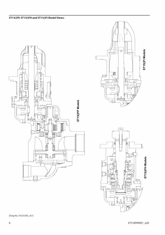
ST15()FP, ST15()FH and ST15()FI Model Views:
ST15
()FP
Mod
els
ST15
()FH
Mod
els
ST15
()FI M
odel
s
(Dwg No. 47555393_sh1)
47518999001_ed2 7
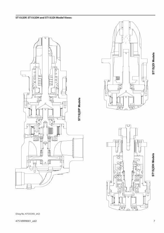
ST15()DP, ST15()DH and ST15()DI Model Views:
ST15
()DP
Mod
els
ST15
()DI M
odel
sST
15()D
H M
odel
s
(Dwg No. 47555393_sh2)

8 47518999001_ed2
Troubleshooting
Trouble Probable Cause Solution
Motor will not run No air supply Check for blockage or damage to air supply lines or tank.
Damaged motor assembly Inspect motor assembly and power train and repair or replace if necessary.
Foreign material in motor and/or piping
Remove motor assembly and/or piping and remove blockage.
Blocked exhaust system Remove housing exhaust cover and check for blockage.
Defective control valve or relay valve Replace control valve or relay valve.
Low air signal pressure to start valve Check air supply.
Loss of Power Low air pressure to starter Check air supply.
Restricted air supply line Check for blockage or damage to air lines.
Relay valve malfunctioning Clean or replace lines or relay valve. Lube relay valve.
Exhaust flow restricted Check for blocked or damaged piping. Clean or replace piping. Check for dirt or foreign material and clean or remove. Check for ice build-up. Melt ice and reduce moisture build-up to starter.
Damaged motor components Replace damaged components.
For Models with Inertia Drive:
Drive will not engage
Foreign material in starter drive Remove obstruction.
Damaged or worn drive parts Check drive components and replace if necessary.
Motor turning in wrong rotation Wrong combination of drive and motor components. Replace with correct rotation parts.
For Models with Pre-Engaged Drive:
Drive will not engage
No pressure to drive housing port Check air supply.
Internal drive housing ports blocked Remove blockage.
Fluid in drive unit components Remove fluid.
Damaged or worn piston assembly, O-Rings or seals
Replace damaged or worn parts.
O-Rings and seals dry Re-lube O-Rings and seals.
Defective control valve Replace control valve
Motor runs and pinion engages, but does not rotate flywheel
Damaged or broken drive train Disassemble drive train and replace worn or damaged parts.
Motor turning in wrong rotation Wrong combination of drive and motor components. Replace with correct rotation parts.
Excessive butt engagement
Damaged drive pinion or flywheel Inspect drive pinion and flywheel and replace if necessary.
Damaged starter drive or components Inspect drive components and replace worn or damaged parts.
Low air pressure Check air supply.
Wrong drive pinion Replace with proper drive pinion.
Oil blowing out of exhaust
Oil in air supply line Inspect air line and remove source of oil including inline lubricators.
Worn or damaged rotor seals or static O-Rings
Replace static seals on outside of motor or send motor to Ingersoll Rand to be rebuilt.
Test and Inspection Procedure
1. Clutch Ratcheting: Turn the drive pinion by hand in the direction of starter rotation. The clutch should ratchet smoothly with a slight clicking action.
2. Motor and Gearing Freeness: Turn the drive pinion opposite the direction of Starter rotation. The pnion should turn by hand.
3. Pinion Engagement: Apply 50 psig (3.4 bar) pressure air to the engagement “I” port while leaving the “O” port open. The drive pinion should move outward and air should escape from the “O” port. Repeat several times to ensure proper operation. Plug the “O” port and apply 150 psig (10.3 bar) to the “I” port. Check and make sure no air or gas is escaping.
4. Motor Action: Secure starter in a vise and apply 90 psig (6.2 bar) pressure using a 3/8” (9 mm) supply line to the inlet of the motor. Starter should run smoothly and in the direction stamped on the nameplate. Chamfer on pinion teeth should be on trailing edge of gear tooth.
5. Motor and Gear Case Seals: Plug the exhaust and slowly apply 20 psig (1.4 bar) pressure to the inlet of the motor. Immerse the starter for 30 seconds in a nonflammable, bubble-producing liquid. If the starter is properly sealed, no bubbles will appear.
47518999001_ed2 9
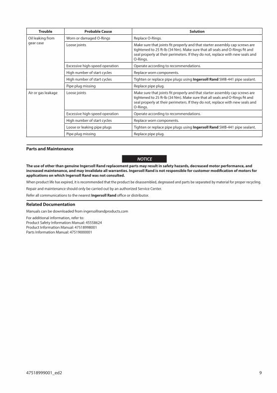
Trouble Probable Cause Solution
Oil leaking from gear case
Worn or damaged O-Rings Replace O-Rings.
Loose joints Make sure that joints fit properly and that starter assembly cap screws are tightened to 25 ft-lb (34 Nm). Make sure that all seals and O-Rings fit and seal properly at their perimeters. If they do not, replace with new seals and O-Rings.
Excessive high-speed operation Operate according to recommendations.
High number of start cycles Replace worn components.
High number of start cycles Tighten or replace pipe plugs using Ingersoll Rand SMB-441 pipe sealant.
Pipe plug missing Replace pipe plug.
Air or gas leakage Loose joints Make sure that joints fit properly and that starter assembly cap screws are tightened to 25 ft-lb (34 Nm). Make sure that all seals and O-Rings fit and seal properly at their perimeters. If they do not, replace with new seals and O-Rings.
Excessive high-speed operation Operate according to recommendations.
High number of start cycles Replace worn components.
Loose or leaking pipe plugs Tighten or replace pipe plugs using Ingersoll Rand SMB-441 pipe sealant.
Pipe plug missing Replace pipe plug.
Parts and Maintenance
NOTICEThe use of other than genuine Ingersoll Rand replacement parts may result in safety hazards, decreased motor performance, and increased maintenance, and may invalidate all warranties. Ingersoll Rand is not responsible for customer modification of motors for applications on which Ingersoll Rand was not consulted.
When product life has expired, it is recommended that the product be disassembled, degreased and parts be separated by material for proper recycling.
Repair and maintenance should only be carried out by an authorized Service Center.
Refer all communications to the nearest Ingersoll Rand office or distributor.
Related DocumentationManuals can be downloaded from ingersollrandproducts.com
For additional information, refer to:Product Safety Information Manual: 45558624Product Information Manual: 47518998001Parts Information Manual: 47519000001

Notes:

Notes:

ingersollrandproducts.com
© 2017 Ingersoll Rand