Embed Size (px)
Citation preview
Air operated 2 port valve (cylinder valve)SAB/SVB Series
New Product
2 PORT AIR OPERATED VALVE
New Products
4CC-770A
Machine
Food
Precise and measurement, etc
Automobile
Chemistry
Semiconductor
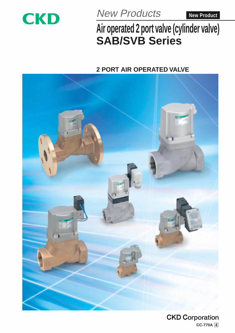
SAB/SVB series variationPort size
80F65F50A/F40A/F32A/F25A20A15A10A8A
2 port valve
Applicable fluidsModel
Water and liquid
Air/gas
Low vacuum
For steam
SAB/SVB*W
SAB/SVB*A
SAB/SVB*V
SAB/SVB*S
Compact/energy saving actuator
Low wattage coil
Achieving higher energy saving performance and ultimate compact size SAB/SVB SeriesSmall,Smart
Usable from water, air, gas, low vacuum, steam to high viscosity fluid or powder mixed fluids, etc., and compatible with wide applications.
Compact and energy savingOperation air consumption reduced by 40% maximum (*1)
Actuator size (volume) reduced by 50% maximum (*1)
*1. Comparison with conventional NAB Series*2. Excluding port size 65F and 80F
Stable operation, durable to foreign matters and compatible with different fluids
Air operated 2 port valve
50% downsized
40% cut
Actuator
Same clearance
VolumeApproximate max.
Air consumptionApproximate max.
Free actuator installation attitude
Freely combined to any 4 directions
Usable in flammable environment
Due to air operated perfect structure, SAB can be used in the flammable environment.
With incorporated solenoid valve available by valve for steam
Air operated type and solenoid valve integrated type are newly added in the series. This CKD original solenoid valve integrated type is realized with advanced technologies including new heat resistance and insulation materials.
Safe and reliable operation
Cylinder driven by external pilot airOperation is foreign matter high reliability equipped by certain strongly.
Wide variation
Two types of body material (bronze and stainless steel) and 4 types of sealant (nitrile rubber, fluoro rubber, ethylene propylene diene rubber and tetrafluoroethylene resin) are available in accordance with working fluid. 13 types of port size, 3 types of actuation are available, and solenoid valve integrated type to drive cylinders are also available.
MPa MADE IN JAPAN
Ultimate compact size is realized in "Small" and
"Smart" concept.
Incorporating new flow path in the body,
remarkably compacts actuator with conventional
products performance is now available.
*My body face to face dimensions have conventional products NAB series and compatibility.
2 P O R T A I R O P E R A T E V A L V E
SAB•SVB Series
Power consumption reduced by 50%Power consumption is reduced to 2W form conventional 4W (DC).
Intro 2
SAB/SVB SeriesSeries variation
Port size
Page
1
5
9
13
17
25
29
33
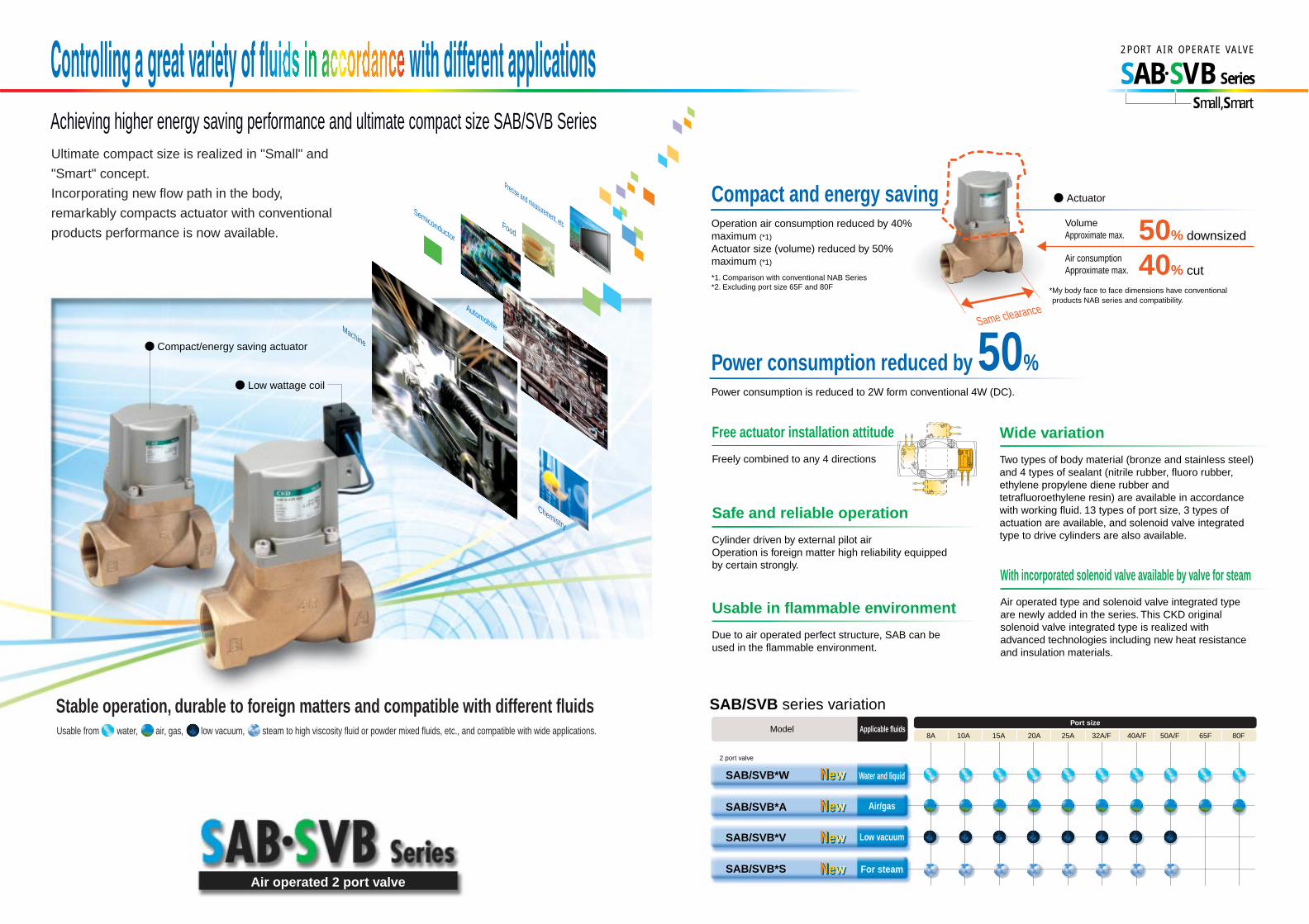
Rc3/4 Rc1 Rc1 1/4 32Flange
Rc1 1/2 40Flange
Rc2 50Flange
65Flange
80Flange
Intro 1
Air operated 2 port valve(Cylinder valve)
Seriesvariation
Category
Air operated type
With solenoid valve
Water, liquid
SAB*W
Air/gas
SAB*A
Low vacuum
SAB*V
Steam, water, air
SAB*S
Water, liquid
SVB*W
Air/gas
SVB*A
Low vacuum
SVB*V
Steam, water, air
SVB*S
Model name
No.
of p
ort
Actuation
NC NODouble actingoperation Rc1/4 Rc3/8 Rc1/2
2 po
rt
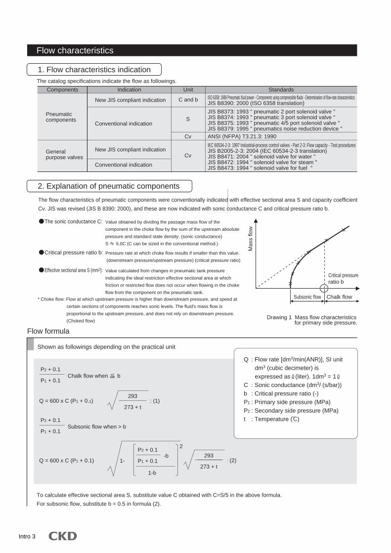
Flow characteristics
1. Flow characteristics indicationThe catalog specifications indicate the flow as followings.
UnitIndicationComponents Standards
New JIS compliant indication
Pneumaticcomponents
Generalpurpose valves
New JIS compliant indication
Conventional indication
Conventional indication
C and b
S
Cv
Cv
ISO 6358: 1989 Pneumatic fluid power - Components using compressible fluids - Determination of flow-rate characteristicsJIS B8390: 2000 (ISO 6358 translation)
JIS B8373: 1993 " pneumatic 2 port solenoid valve "JIS B8374: 1993 " pneumatic 3 port solenoid valve "JIS B8375: 1993 " pneumatic 4/5 port solenoid valve "JIS B8379: 1995 " pneumatics noise reduction device "ANSI (NFPA) T3.21.3: 1990
IEC 60534-2-3: 1997 Industrial-process control valves - Part 2-3: Flow capacity - Test proceduresJIS B2005-2-3: 2004 (IEC 60534-2-3 translation)JIS B8471: 2004 " solenoid valve for water "JIS B8472: 1994 " solenoid valve for steam "JIS B8473: 1994 " solenoid valve for fuel "
The flow characteristics of pneumatic components were conventionally indicated with effective sectional area S and capacity coefficient
Cv. JIS was revised (JIS B 8390: 2000), and these are now indicated with sonic conductance C and critical pressure ratio b.
* Choke flow: Flow at which upstream pressure is higher than downstream pressure, and speed at
certain sections of components reaches sonic levels. The fluid's mass flow is
proportional to the upstream pressure, and does not rely on downstream pressure.
(Choked flow)
Pressure rate at which choke flow results if smaller than this value.
(downstream pressure/upstream pressure) (critical pressure ratio)
Value calculated from changes in pneumatic tank pressure
indicating the ideal restriction effective sectional area at which
friction or restricted flow does not occur when flowing in the choke
flow from the component on the pneumatic tank.
Flow formula
To calculate effective sectional area S, substitute value C obtained with C=S/5 in the above formula.
For subsonic flow, substitute b = 0.5 in formula (2).
Shown as followings depending on the practical unit
P2 + 0.1
P1 + 0.1
P2 + 0.1
P1 + 0.1Subsonic flow when > b
Q = 600 x C (P1 + 0.1) : (1)
293
273 + t
293
273 + t
Q = 600 x C (P1 + 0.1) : : (2)
P2 + 0.1
P1 + 0.11--b
2
1-b
2. Explanation of pneumatic components
Drawing 1 Mass flow characteristics for primary side pressure.
Subsonic flow Chalk flow
Critical pressureratio b
Mas
s flo
w
The sonic conductance C:
Critical pressure ratio b:
Effective sectional area S (mm2):
Value obtained by dividing the passage mass flow of the
component in the choke flow by the sum of the upstream absolute
pressure and standard state density. (sonic conductance)
S 5.0C (C can be sized in the conventional method.)
Chalk flow when b
Q : Flow rate [dm3/min(ANR)], SI unit dm3 (cubic decimeter) is expressed as (liter). 1dm3 = 1
C : Sonic conductance (dm3/ (s/bar))b : Critical pressure ratio (-)P1 : Primary side pressure (MPa)P2 : Secondary side pressure (MPa)t : Temperature ( )
Intro 3

The general purpose valve flow characters are indicated with capacity coefficient Cv. To comply with old IEC Standards, attempts
were made to indicate features with capacity coefficient Av to unify indications with SI units. The Av value was eliminated from the
control valve capacity coefficient with JIS B 2005-2-3: 2004 revisions, and only Kv and Cv types are used. The Cv indication is still
used to indicate flow features of the general purpose valves. For Av values, conversion values are listed for reference as needed.
Flow formula
Shown as followings depending on the practical unit
Capacity coefficient Cv
For liquid:
For steam:
3. Explanation of general purpose valves
Cv : Flow factorW : Flow (kg/h)P1 : Primary absolute pressure (MPa)P2 : Secondary absolute pressure (MPa)K : (1 + 0.0013ts) ts: Degree of superheat
(Saturated vapor K = 1)
Q = 45.16 Cv : (5)
For P2 : (6)
The non-SI adjustment valve capacity coefficient is used commonly worldwide. U.S. gal value indicating the flow
of 40 to 100°F city water for one minute through the valve (test part) when the differential pressure is 1 psi.
Cv = Q : (3)
Value indicating city water flow rate passing through valve (test part) as m3/s unit at pressure difference 1 Pa.
The value is calculated based on the following formula.
Av = Q : (4)
P1
2W =
97 Cv P1
K
For P2 > : (7)P1
2W =
194 Cv (P1 -P2 ) P2
K
Capacity
coefficient Cv
Capacity
coefficient Av
1
P
P
G
Cv : Flow factorQ : Flow ( /min) P : Differential pressure (MPa)G : Specific gravity (water G = 1)
Av : Capacity coefficient (m2)Q : Flow (m3/s)
: Fluid density (kg/m3) P : Differential pressure (Pa)
Cv : Capacity coefficientQ : Flow (U.S.gal/min) (1U.S.gal/min. = 6,309 x 10-5m3/s)
: Fluid density (1b/ft3) (1b/ft3 = 16,018kg/m3) w : 40°F to 100°F (4 to 38 ) water density (1b/ft3) P : differential pressure (psi) (1psi = 6.8948kPa)
w
P
:
:
Intro 4
Intro 5
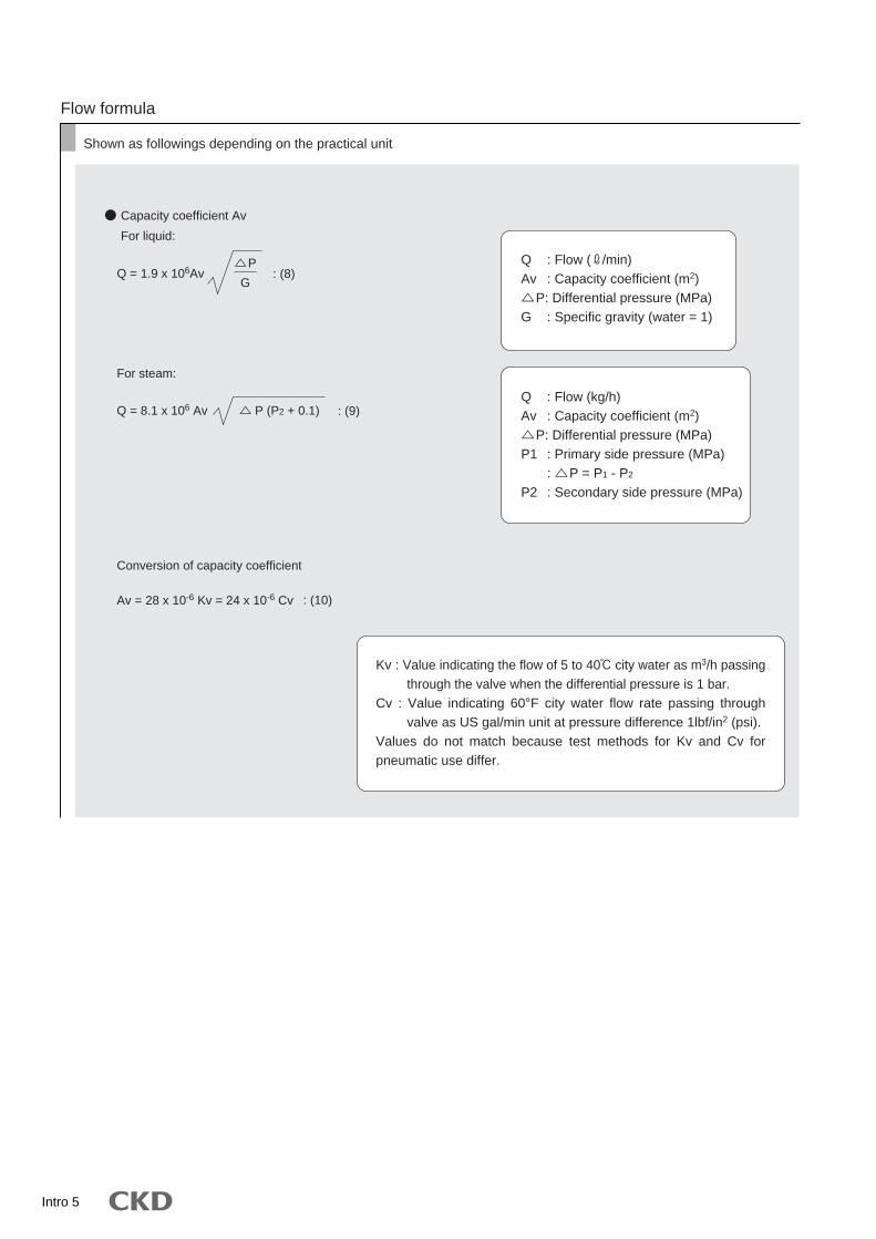
Flow formula
Shown as followings depending on the practical unit
Capacity coefficient Av
For liquid:
For steam:
Av = 28 x 10-6 Kv = 24 x 10-6 Cv : (10)
Q = 1.9 x 10⁶Av : (8)
Q = 8.1 x 10⁶ Av : (9)
Conversion of capacity coefficient
P
G
P (P2 + 0.1)
Q : Flow ( /min)Av : Capacity coefficient (m2) P: Differential pressure (MPa)G : Specific gravity (water = 1)
Q : Flow (kg/h)Av : Capacity coefficient (m2) P: Differential pressure (MPa)P1 : Primary side pressure (MPa)
: P = P1 - P2
P2 : Secondary side pressure (MPa)
Kv : Value indicating the flow of 5 to 40 city water as m3/h passing through the valve when the differential pressure is 1 bar.
Cv : Value indicating 60°F city water flow rate passing through valve as US gal/min unit at pressure difference 1lbf/in2 (psi).
Values do not match because test methods for Kv and Cv for pneumatic use differ.
Intro 6
M E M OM E M O

Intro 7
1
2
3
4
5
1
23
4
The safety cautions are ranked as "DANGER", "WARNING" and "CAUTION" in this section.
DANGER :
WARNING:
CAUTION :
WARNING
When designing and manufacturing a device using CKD products, the manufacturer is obligated to check that device safety mechanical mechanism, pneumatic control circuit, or water control circuit and the system operated by electrical control that controls the devices is secured.It is important to select, use, handle, and maintain the product appropriately to ensure that the CKD product is used safely.Observe warnings and precautions to ensure device safety.Check that device safety is ensured, and manufacture a safe device.
This product is designed and manufactured as a general industrial machine part. It must be handled by an operator having sufficient knowledge and experience in handling.
Use this product in accordance of specifications.
Observe corporate standards and regulations, etc., related to the safety of device design and control, etc.
Observe warnings and cautions on the pages below to prevent accidents.
Do not handle, pipe, or remove devices before confirming safety.
1
2
Contact CKD when using the product outside the unique specifications range, when using it outdoors, and when using it under the conditions and environment below. Do not attempt to modify or additionally machine the product.
Use for special applications requiring safety including nuclear energy, railroad, aviation, ship, vehicle, medical equipment, equipment, or applications coming into contact with beverage or food, amusement equipment, emergency shutoff circuits, press machine, brake circuits, or for safeguard.Use for applications where life or assets could be adversely affected, and special safety measures are required.
Inspect and service the machine and devices after confirming safety of the entire system related to this product.Note that there may be hot or charged sections even after operation is stopped.When inspecting or servicing the device, turn off the energy source (air supply or water supply), and turn off power to the facility. Discharge any compressed air from the system, and pay enough attention to possible water leakage and leakage of electricity.When starting or restarting a machine or device that incorporates pneumatic components, make sure that the system safety, such as pop-out prevention measures, is secured.
ISO4414, JIS B8370 (pneumatic system rules)Including High Pressure Gas Maintenance Law, Occupational Safety and Sanitation Laws, other safety rules, body standards and regulations, etc.
Note that some items described as "CAUTION" may lead to serious results depending on the situation. In any case, important information that must be observed is explained.
Safety precautionsAlways read this section before starting use.
Fluid control components
When a dangerous situation may occur if handling is mistaken leading to fatal or serious injuries, or when there is a high degree of emergency to a warning.
When a dangerous situation may occur if handling is mistaken leading to fatal or serious injuries.
When a dangerous situation may occur if handling is mistaken leading to minor injuries or physical damage.
Intro 8
Design & Selection
This product can not be used as an emergency shutoff valve.Valves in this catalog are not designed to ensure safety suchas emergency shutoff. When using in this system, take sepa-rate measures that will ensure safety.
Take measures to prevent harm to operators or ob-jects if this product fails
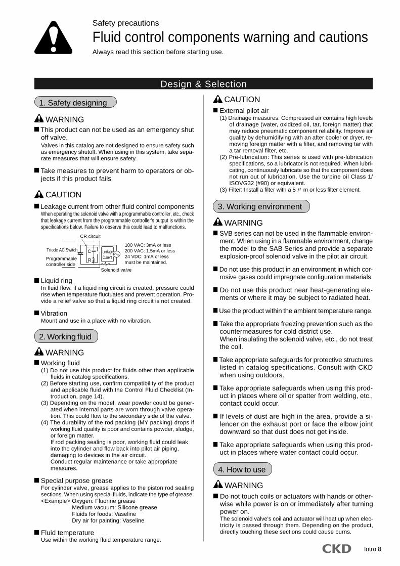
Leakage current from other fluid control componentsWhen operating the solenoid valve with a programmable controller, etc., checkthat leakage current from the programmable controller's output is within thespecifications below. Failure to observe this could lead to malfunctions.
Liquid ringIn fluid flow, if a liquid ring circuit is created, pressure couldrise when temperature fluctuates and prevent operation. Pro-vide a relief valve so that a liquid ring circuit is not created.
VibrationMount and use in a place with no vibration.
Safety precautions
Fluid control components warning and cautionsAlways read this section before starting use.
100 VAC: 3mA or less200 VAC: 1.5mA or less24 VDC: 1mA or lessmust be maintained.
CR circuit
Triode AC Switch LeakageCurrent
C
R
Solenoid valve
Programmablecontroller side
Working fluid(1) Do not use this product for fluids other than applicable
fluids in catalog specifications.(2) Before starting use, confirm compatibility of the product
and applicable fluid with the Control Fluid Checklist (In-troduction, page 14).
(3) Depending on the model, wear powder could be gener-ated when internal parts are worn through valve opera-tion. This could flow to the secondary side of the valve.
(4) The durability of the rod packing (MY packing) drops ifworking fluid quality is poor and contains powder, sludge,or foreign matter.If rod packing sealing is poor, working fluid could leakinto the cylinder and flow back into pilot air piping,damaging to devices in the air circuit.Conduct regular maintenance or take appropriatemeasures.
Special purpose greaseFor cylinder valve, grease applies to the piston rod sealingsections. When using special fluids, indicate the type of grease.<Example> Oxygen: Fluorine grease
Medium vacuum: Silicone greaseFluids for foods: VaselineDry air for painting: Vaseline
Fluid temperatureUse within the working fluid temperature range.
WARNING
WARNING
CAUTION
2. Working fluid
CAUTION1. Safety designing External pilot air(1) Drainage measures: Compressed air contains high levels
of drainage (water, oxidized oil, tar, foreign matter) thatmay reduce pneumatic component reliability. Improve airquality by dehumidifying with an after cooler or dryer, re-moving foreign matter with a filter, and removing tar witha tar removal filter, etc.
(2) Pre-lubrication: This series is used with pre-lubricationspecifications, so a lubricator is not required. When lubri-cating, continuously lubricate so that the component doesnot run out of lubrication. Use the turbine oil Class 1/ISOVG32 (#90) or equivalent.
(3) Filter: Install a filter with a 5 m or less filter element.
SVB series can not be used in the flammable environ-ment. When using in a flammable environment, changethe model to the SAB Series and provide a separateexplosion-proof solenoid valve in the pilot air circuit.
Do not use this product in an environment in which cor-rosive gases could impregnate configuration materials.
Do not use this product near heat-generating ele-ments or where it may be subject to radiated heat.
Use the product within the ambient temperature range.
Take the appropriate freezing prevention such as thecountermeasures for cold district use.When insulating the solenoid valve, etc., do not treatthe coil.
Take appropriate safeguards for protective structureslisted in catalog specifications. Consult with CKDwhen using outdoors.
Take appropriate safeguards when using this prod-uct in places where oil or spatter from welding, etc.,contact could occur.
If levels of dust are high in the area, provide a si-lencer on the exhaust port or face the elbow jointdownward so that dust does not get inside.
Take appropriate safeguards when using this prod-uct in places where water contact could occur.
WARNING
Do not touch coils or actuators with hands or other-wise while power is on or immediately after turningpower on.The solenoid valve's coil and actuator will heat up when elec-tricity is passed through them. Depending on the product,directly touching these sections could cause burns.
WARNING
4. How to use
3. Working environment

Intro 9
When not using the product for one or more monthsafter using water or hot water, remove any water orhot water left in the product. Water or hot water resi-due will cause rusting and may lead to operationfaults or leaks.If residual water cannot be removed, operate thevalve several times a day to ensure correct use.
5. Securing of space
Secure sufficient space for maintenance and inspec-tion.
CAUTION
Do not step the valve, nor put the heavy things on it.
When using the product with continuous energizingand low frequency, consult with CKD.
If the product has not been used for more than amonth, carry out trial operation.
Do not touch electric wiring connections with hands or otherwise (barecharged sections) while power is on. An electric shock could occur.Touching electric wire connections while power is on couldlead to electrical shock.
Use within the maximum service pressure and maxi-mum working pressure difference range.
CAUTION
When piping the SAB or SVB Series, pay attention tothe supply port on the unit and pilot operation side.
CAUTION
1. Installation
Always thoroughly read the Instruction Manual be-fore installing this product.
Do not apply external force to the coil section whena solenoid valve is installed.
After installing, check for leaks from pipes and for wireconnections, and check that the product is correctly installed.
CAUTION Observe the valid thread length for piping. Chamferthe end of the screw a half-pitch.
Before piping, flush the inside of the pipe with 0.3MPa of air, and remove foreign matter such as dirt,metal chips, rust, and sealing tape.
If excessive sealant (tape, gel) is applied when pip-ing, it could enter the product and cause operationfaults.
When applying or wrapping sealant on piping mate-rial, apply it or wind it from the pipe end along thescrew and leave 1.5 to 2 threads uncovered.
Dirt or foreign matter in fluid may prevent the productfrom functioning correctly. Install an 80 mesh or higherfilter for water flow, and a 5 m or less filter for air flow.
Do not mistake the supply port when piping to theproduct.
Do not pipe with using a solenoid valve section. Failure to ob-serve this, the product could be damaged. (For solenoid valve)
Install the by-pass circuit, and use the elbow unionwhen piping to simplify the maintenance or repairwork.
When controlling fluid in a tank, pipe at a level slightlyabove the bottom of the tank.
2. Piping
SAB/SVB Series
XY
X and YXY
X and YXY
X and YXY
X and YPPPPPPPP
AAABA
A or BAAABA
A or BAABAAABA
Model no.
SAB1WSAB2WSAB3WSAB1ASAB2ASAB3ASAB1VSAB2VSAB3VSAB1SSAB2SSAB3SSVB1WSVB2WSVB1ASVB2ASVB1VSVB2VSVB1SSVB2S
Pilot operation sidesupply port
Body sidesupply port
Note 1) With the SAB V or SVB V side port, connect the chamber (vacuum holding side) to port A.
123
12
Note that when using for vacuum break, etc., set the pressurized port to port A.
Chamber
Vacuum pump
A B
V.P
When operating a hydraulic cylinder with a cylindervalve for water, if the valve's B port is piped to thecylinder, pressure in the valve's B port and pipingrises and apply excessive pressure on the valve body,leading to damage. In this case, pipe the valve's Aport to the cylinder side.
A B
A B
Sealed
Example of improper use)
Sealed AB
AB
Example of proper use)
Installation & Adjustment
Intro 10
SAB/SVB Series
7 to 9Nominal piping diameter
Rc1/8Recommended piping tightening torque (N m)
Refer to the table below for tightening torque of thepilot air when piping.
Refer to the table below for tightening torque when piping.
23 to 2531 to 3341 to 4362 to 6583 to 86
97 to 100104 to 108132 to 136
<Product/body section piping>
Nominal piping diameterRc1/4Rc3/8Rc1/2Rc3/4Rc1Rc1 1/4Rc1 1/2Rc2
Recommended piping tightening torque (N m)
CAUTION
3. Wiring
Use the product within the allowable voltage range.Use outside of the allowable voltage range may leadto operation faults or coil damage.
Use a breaker such as the fuse, etc., on the controlcircuit for maintenance of electric equipment.
If the electrical circuit is susceptible to solenoid surge,use a solenoid with a surge suppressor (option), orinsert a surge absorber, etc., parallel to the solenoid.
Use a wire with nominal section area 0.5mm2 andover as the reference. Check that no excessive forceis applied to leads.
When using an explosion-proof solenoid valve, fol-low explosion-proof policy when wiring.
Use of a switching circuit that does not cause con-tact chatter will lengthen the life of the solenoid valveand motorized valve.
Wiring when solenoid valve is installed.(1) Refer to connections on page 13 in the introduction when
wiring to a DIN terminal box or T-type terminal box.(2) The size of the screw for the DIN terminal box's junction
box outlets can be changed from Pg9 to G1/2 using theoptional connector below.
(3) Coil orientation is changed by 180°. Turn the coil onlywhen reversing the electric wire connection method. Donot lose internal parts when removing the coil.
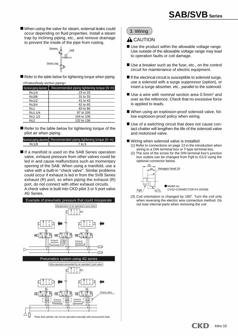
When using the valve for steam, external leaks couldoccur depending on fluid properties. Install a steamtrap by inclining piping, etc., and remove drainageto prevent the inside of the pipe from rusting.
Steam trap
StrainerSAB
Hexagon head 2425
16
Pg9 G/1 2
Model no.:CVS2-CONNECTOR-F4-202936
If a manifold is used on the SAB Series operationvalve, exhaust pressure from other valves could beled in and cause malfunctions such as momentaryopening of the SAB. When using a manifold, use avalve with a built-in "check valve". Similar problemscould occur if exhaust is led in from the SVB Seriesexhaust (R) port, so when piping the exhaust (R)port, do not connect with other exhaust circuits.A check valve is built into CKD pilot 3 or 5 port valve4G Series.
Example of pneumatic pressure that could misoperate
Pneumatics system using 4G series
Misoperation of air-operated 2-port valve
Exh
aust
pres
sure
Exhaustpressure
Exhaustpressure
Miss-operation prevented for air operated 2 port valve
Exhaustpressure
Exhaustpressure
Check valve
*Note that cylinder can not be operated manually with pressurized state.
Intro 11
When cleaning the product, use a low-polluting clean-ing agent such as a neutral detergent. (Note that rub-ber parts must be replaced if they expand.)
Consult with CKD on questions about consumables,etc.
A spring is used in the cylinder cover. When disas-sembling this type, the spring could pop out andcause injuries, so take care. The NC (normallyclosed) has a snap ring to prevent the spring frompopping out. Do not remove the snap ring.
WARNING
CAUTION
2. Assembling & Disassembling
SAB/SVB Series
To ensure that the product is used optimally, regu-larly inspect the product every six months. This fre-quency varies with the frequency of use.
CAUTION Read the instruction manual thoroughly before start-ing maintenance to ensure correct operation.
Turn power off and release fluids or pressure beforestarting maintenance.
Care must be taken not to clog the strainer-filter.
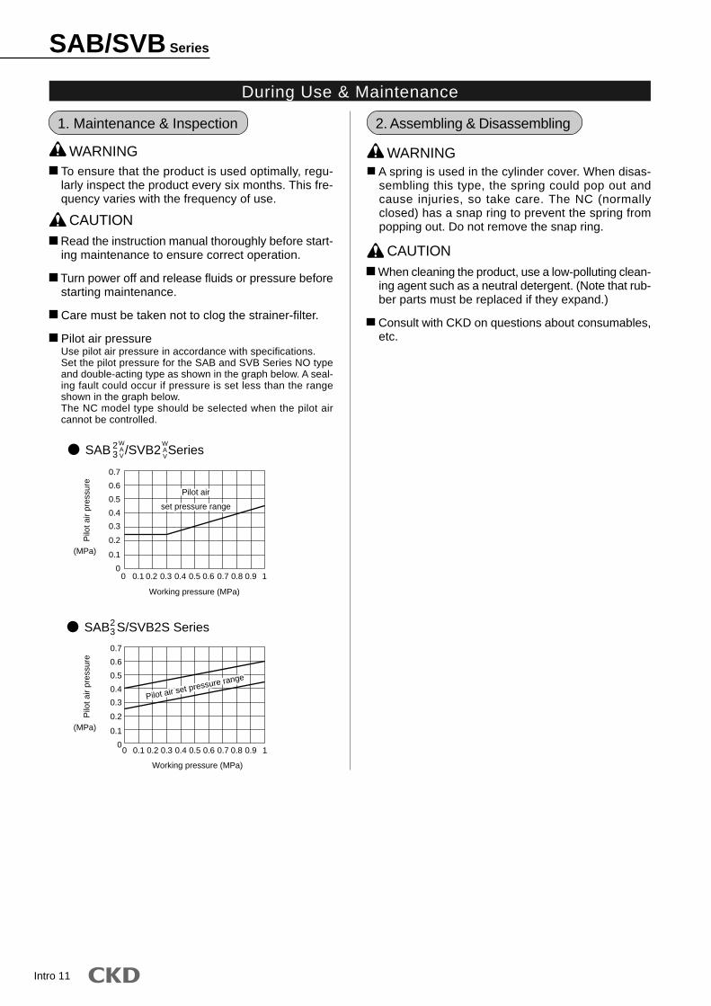
Pilot air pressureUse pilot air pressure in accordance with specifications.Set the pilot pressure for the SAB and SVB Series NO typeand double-acting type as shown in the graph below. A seal-ing fault could occur if pressure is set less than the rangeshown in the graph below.The NC model type should be selected when the pilot aircannot be controlled.
1. Maintenance & Inspection
WARNING
During Use & Maintenance
Working pressure (MPa)
Working pressure (MPa)
Pilo
t air
pres
sure
0.4
0.5
0.6
0.7
0.3
0.2
0.1
00 0.1 0.2 0.3 0.4 0.5 0.6 0.7 0.8 0.9 1
0 0.1 0.2 0.3 0.4 0.5 0.6 0.7 0.8 0.9 1
23
WAV
WAV
23
(MPa)
Pilo
t air
pres
sure
(MPa)
Pilot air
set pressure range
Pilot air
set pressure range
Pilot air set pressure range
Pilot air set pressure range
Pilot air set pressure range0.4
0.5
0.6
0.7
0.3
0.2
0.1
0
SAB /SVB2 Series
SAB S/SVB2S Series
Intro 12
SAB/SVB Series
CAUTION
*1
*1
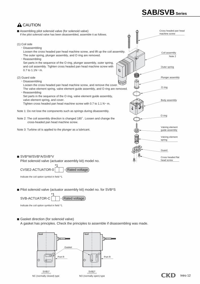
Assembling pilot solenoid valve (for solenoid valve)If the pilot solenoid valve has been disassembled, assemble it as follows.
(1) Coil sideDisassemblingLoosen the cross headed pan head machine screw, and lift up the coil assembly.The outer spring, plunger assembly, and O ring are removed.ReassemblingSet parts in the sequence of the O ring, plunger assembly, outer spring,and coil assembly. Tighten cross headed pan head machine screw with0.7 to 1.1N m.
(2) Guard sideDisassemblingLoosen the cross headed pan head machine screw, and remove the cover.The valve element spring, valve element guide assembly, and O ring are removed.ReassemblingSet parts in the sequence of the O ring, valve element guide assembly,valve element spring, and cover.Tighten cross headed pan head machine screw with 0.7 to 1.1 N m.
Note 1: Do not lose the components such as springs during disassembly.
Note 2: The coil assembly direction is changed 180゚. Loosen and change the cross-headed pan head machine screw.
Note 3: Turbine oil is applied to the plunger as a lubricant.
Gasket direction (for solenoid valve)A gasket has principles. Check the principles to assemble if disassembling was made.
SVB*W/SVB*A/SVB*VPilot solenoid valve (actuator assembly kit) model no.
CVSE2-ACTUATOR-0 - Rated voltage
Indicate the coil option symbol in field *1.
Pilot solenoid valve (actuator assembly kit) model no. for SVB*S
SVB-ACTUATOR-C - Rated voltage
Indicate the coil option symbol in field *1.
Cross headed pan headmachine screw
Body assembly
Cross headed flathead screw
Valving elementguide assembly
Valving elementspring
Guard
O ring
O ring
Plunger assembly
Coil assembly
Outer spring
Note 2
SVB2*SVB1*
NO (normally open) typeNC (normally closed) type
Port R Port R
Gasket
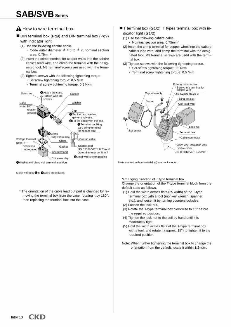
DIN terminal box (Pg9) and DIN terminal box (Pg9)with indicator light(1) Use the following cabtire cable.
• Code outer diameter: 4.5 to 7, nominal sectionarea: 0.75mm2
(2) Insert the crimp terminal for copper wires into the cabtirecable's lead wire, and crimp the terminal with the desig-nated tool. M3 terminal screws are used with the termi-nal box.
(3) Tighten screws with the following tightening torque.• Setscrew tightening torque: 0.5 N•m• Terminal screw tightening torque: 0.5 N•m
* The orientation of the cable lead out port is changed by re-moving the terminal box from the case, rotating it by 180°,then replacing the terminal box into the case.
How to wire terminal box T terminal box (G1/2), T types terminal box with in-dicator light (G1/2)(1) Use the following cabtire cable.
• Nominal section area: 0.75mm2
(2) Insert the crimp terminal for copper wires into the cabtirecable's lead wire, and crimp the terminal with the desig-nated tool. M3 terminal screws are used with the termi-nal box.
(3) Tighten screws with the following tightening torque.• Set screw tightening torque: 0.5 N•m• Terminal screw tightening torque: 0.5 N•m
*Changing direction of T type terminal boxChange the orientation of the T-type terminal block from thedefault state as follows.(1) Hold the width across flats (25 width) of the T-type
terminal box with a tool (monkey wrench, spanner,etc.), and loosen it by turning counterclockwise.
(2) Loosen the lock nut.(3) Rotate the T-type terminal box clockwise to 15° before
the required position.(4) Tighten the lock nut to the coil by hand until it is
moderately tight.(5) Hold the width across flats of the T-type terminal box
with a tool, and rotate it (approx. 15°) to tighten it to therequired position.
Note: When further tightening the terminal box to change theorientation from the default, rotate it within 1/2-turn.
Intro 13
Attach the case.Tighten with thescrews.
Setscrew Gasket
Washer
CapSet the cap, washer,gasket and case.Fix the cable with the cap.
CaseNote: 180° rotation permissible
Voltage terminalNote: distinction not required
Gland
Gasket
Ground terminal
Coil assembly
bare crimp terminalfor copper wire
Ground cable
Cabtire cord
Gasket and gland coil terminal insertion
Terminal caulking
Lead wire sheath pealing
2
6
7
3
4 GlandCrimp terminal fixing
5
1
Make wiring by to work procedures.1 7
JIS C3306 VCTF 0.75mm2
Outer diameter 4.5 to 7
SAB/SVB Series
Parts marked with an asterisk (*) are not included.
Cap assembly
Gasket
Free terminal screw* Bare crimp terminal for copper wire
Fixing bracket
Coil lead wire
Set screwLock nut
Terminal box
* Cable connector
*600V vinyl insulation vinyl cabtire cableJIS C 3312 VCT 0.75mm2
JIS C2805 R1.25-3
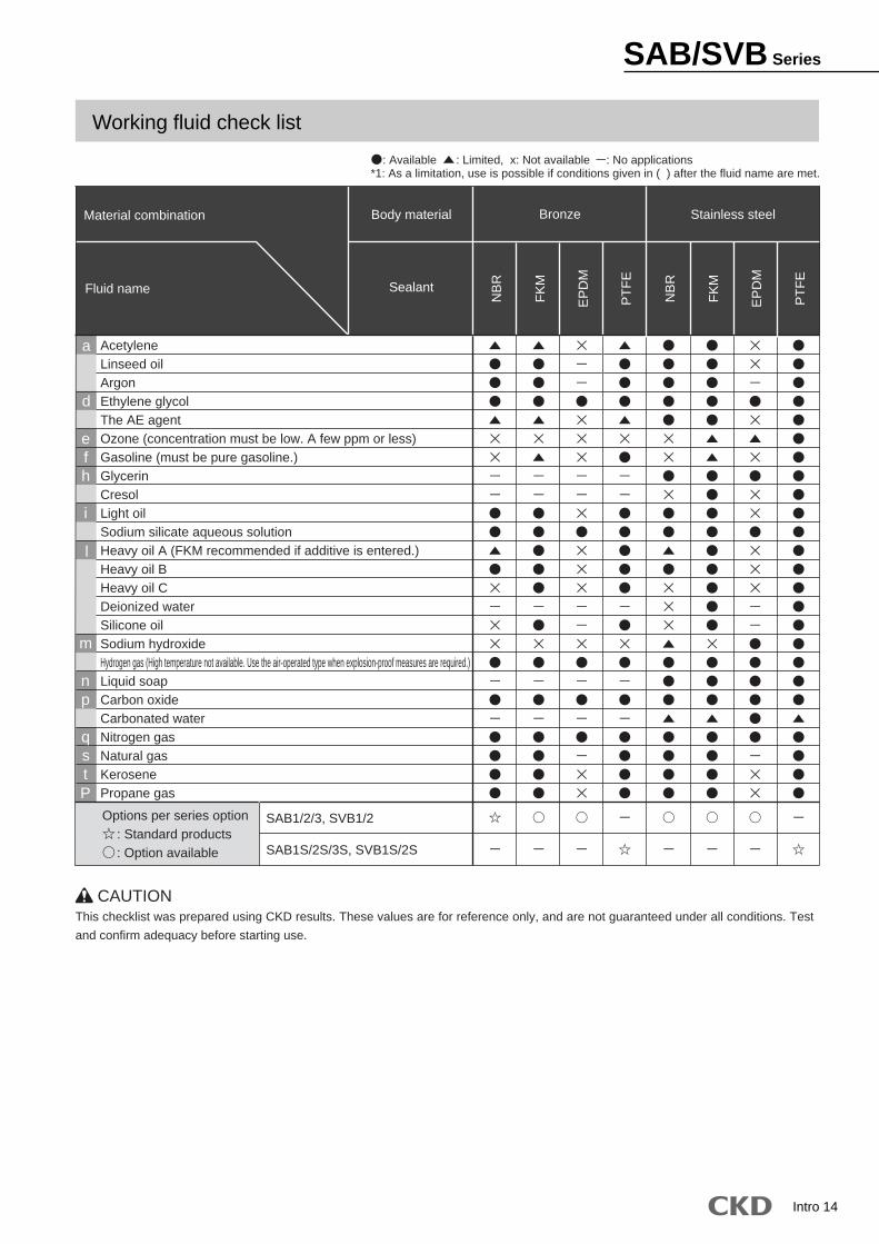
AcetyleneLinseed oilArgonEthylene glycolThe AE agentOzone (concentration must be low. A few ppm or less)Gasoline (must be pure gasoline.)GlycerinCresolLight oilSodium silicate aqueous solutionHeavy oil A (FKM recommended if additive is entered.)Heavy oil BHeavy oil CDeionized waterSilicone oilSodium hydroxideHydrogen gas (High temperature not available. Use the air-operated type when explosion-proof measures are required.)Liquid soapCarbon oxideCarbonated waterNitrogen gasNatural gasKerosenePropane gas
a
d
efh
i
l
m
np
qstP
Material combination
Fluid name
*1: As a limitation, use is possible if conditions given in ( ) after the fluid name are met.
Body material
Sealant
SAB1/2/3, SVB1/2
SAB1S/2S/3S, SVB1S/2S
Bronze Stainless steel
NB
R
FK
M
EP
DM
NB
R
FK
M
EP
DM
PT
FE
CAUTIONThis checklist was prepared using CKD results. These values are for reference only, and are not guaranteed under all conditions. Test
and confirm adequacy before starting use.
PT
FE
: Available : Limited, x: Not available : No applications
Options per series option : Standard products : Option available
Intro 14
SAB/SVB Series
Working fluid check list
1
JIS symbol
B
A
A
X
BY
B
A
X Y
Double acting type
NC (normally closed) type
NO (normally open) type
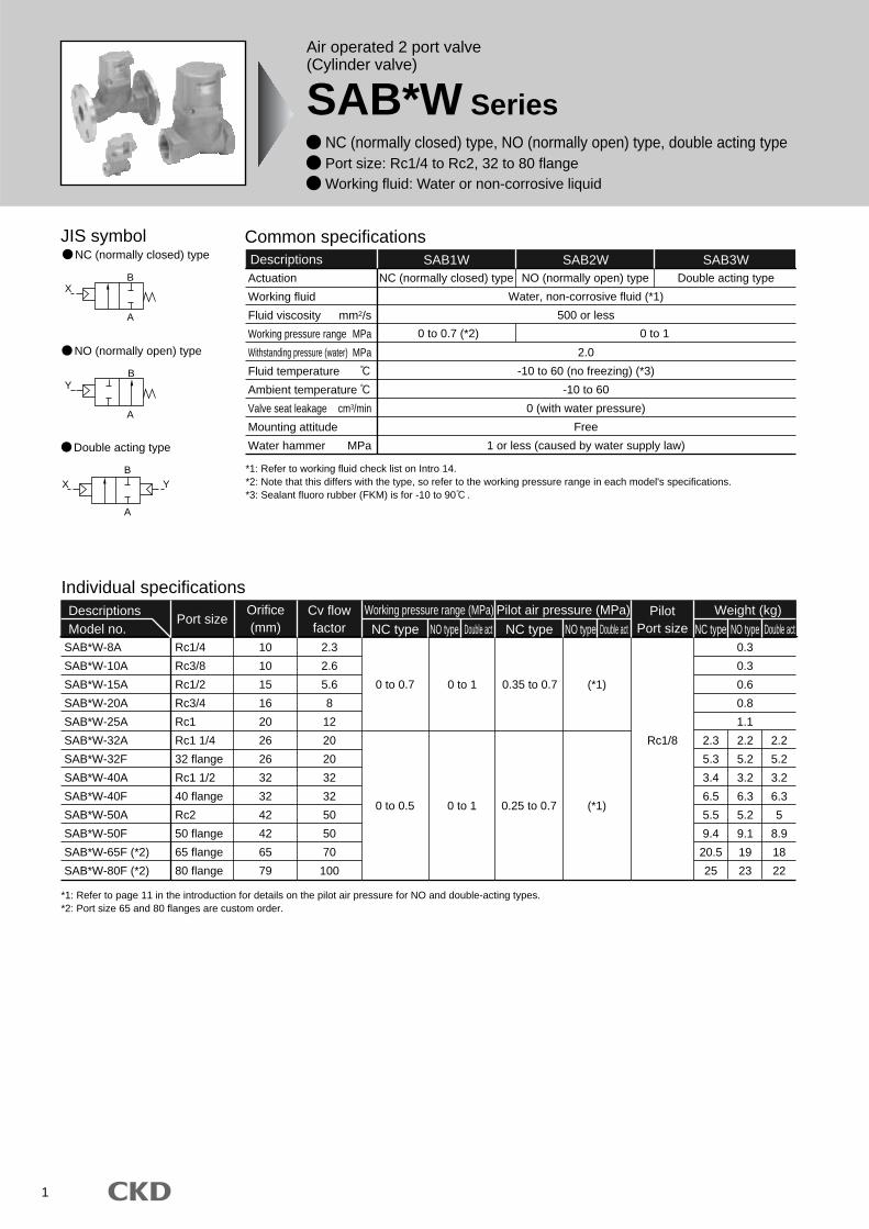
Common specificationsDescriptions SAB1W SAB2W
Water, non-corrosive fluid (*1)
500 or less
2.0
-10 to 60 (no freezing) (*3)
-10 to 60
0 (with water pressure)
Free
1 or less (caused by water supply law)
NC (normally closed) type
0 to 0.7 (*2) 0 to 1
NO (normally open) type
SAB3WDouble acting type
*1: Refer to page 11 in the introduction for details on the pilot air pressure for NO and double-acting types.*2: Port size 65 and 80 flanges are custom order.
Individual specificationsDescriptionsModel no.
Port sizeWeight (kg)Pilot
Port size NC type NO type Double actNC type NO type Double act NC type NO type Double actSAB*W-8A
SAB*W-10A
SAB*W-15A
SAB*W-20A
SAB*W-25A
SAB*W-32A
SAB*W-32F
SAB*W-40A
SAB*W-40F
SAB*W-50A
SAB*W-50F
SAB*W-65F (*2)
SAB*W-80F (*2)
Rc1/4
Rc3/8
Rc1/2
Rc3/4
Rc1
Rc1 1/4
32 flange
Rc1 1/2
40 flange
Rc2
50 flange
65 flange
80 flange
10
10
15
16
20
26
26
32
32
42
42
65
79
2.3
2.6
5.6
8
12
20
20
32
32
50
50
70
100
Rc1/8
0.3
0.3
0.6
0.8
1.1
2.2
5.2
3.2
6.3
5.2
9.1
19
23
2.2
5.2
3.2
6.3
5
8.9
18
22
2.3
5.3
3.4
6.5
5.5
9.4
20.5
25
Orifice(mm)
Working pressure range (MPa) Pilot air pressure (MPa)Cv flowfactor
0 to 10 to 0.7 0.35 to 0.7 (*1)
0 to 0.5 0.25 to 0.70 to 1 (*1)
Actuation
Working fluid
Fluid viscosity mm2/s
Working pressure range MPa
Withstanding pressure (water) MPa
Fluid temperature
Ambient temperature
Valve seat leakage cm3/min
Mounting attitude
Water hammer MPa
*1: Refer to working fluid check list on Intro 14.*2: Note that this differs with the type, so refer to the working pressure range in each model's specifications.*3: Sealant fluoro rubber (FKM) is for -10 to 90 .
Air operated 2 port valve(Cylinder valve)
SAB*W Series NC (normally closed) type, NO (normally open) type, double acting type Port size: Rc1/4 to Rc2, 32 to 80 flange Working fluid: Water or non-corrosive liquid

2
A
15ASAB 1 W B B
Model no.
Working fluid
(Water, liquid)
Actuation
E Assembly direction
B Port size
C Body/sealantmaterial combination
D Other options
How to order
*1: Body/sealant combination symbol is O or B for port size 65F or 80F. Note that the body is made from cast iron.*2: Mounting plate (B in ) can be installed for port size 8A to 32A.*3: Mounting plate assembly position reverse rotation (B-R in ) is for port size 15A to 32A.*4: Clockwise viewed from above with port A facing right.
Model: SABActuation : NC (normally closed) typePort size : Rc1/2Body/sealant combination
: Body-bronze and sealant-fluoro rubberOther options : Mounting plateAssembly direction : No option
<Example of model number>
SAB1W-15A-BB
A
B
C
D
E
Note on model no. selection
Assembly directionE
SAB (air operated type) *2/4Symbol
Direction
Arrangement
B (mounting plate)
Without rotation
AB AB
B-R *3
Mounting plate reverse rotation
indicates pilot port IN.
D
D
ActuationA
Blank
B
No option
Mounting plate
Other optionsD
Blank
R
No option
Mounting plate assembly position reverse rotation
Refer to the following diagram for the layout drawing.
Assembly directionE
0
B
P
D
E
R
Standard
Body
Bronze
Bronze
Bronze
Stainless steel
Stainless steel
Stainless steel
Sealant
Nitrile rubber
Fluoro rubber
Ethylene propylene diene rubber
Nitrile rubber
Fluoro rubber
Ethylene propylene diene rubber
Body/sealant combinationC
Symbol Descriptions
1
2
3
NC (normally closed) type
NO (normally open) type
Double acting type
Port sizeB
8A
10A
15A
20A
25A
32A
32F
40A
40F
50A
50F
65F
80F
Rc1/4
Rc3/8
Rc1/2
Rc3/4
Rc1
Rc1 1/4
32 flange
Rc1 1/2
40 flange
Rc2
50 flange
65 flange (custom order)
80 flange (custom order)
Opt
ion
*2
*3
*1
SAB*W SeriesHow to order

SAB*W Series
3
Internal structure and parts list
SAB*W-8A to 50A (Rc screw-in type)
Dimensions
SAB*W-8A
SAB*W-10A
SAB*W-15A
SAB*W-20A
SAB*W-25A
SAB*W-32A
SAB*W-40A
SAB*W-50A
A
50
71
80
90
125
140
160
B
24
28
35
43
55
61
76
C
12
14.5
17.5
21
27.5
30.5
38
D
41.5
61.5
71
81.5
109.5
130.5
164
E
71.5
94
106.5
120.5
155
179
220
F
32
43
43
53
63
77
95
Rc1/4
Rc3/8
Rc1/2
Rc3/4
Rc1
Rc1 1/4
Rc1 1/2
Rc2
N
37
38
38
41.5
46
53
61
Model no.
No.
1
2
3
4
5
6
7
8
9
Parts name
Cylinder guard
Piston
Adaptor
Piston rod
Main valving
element
Body
Spring
O ring
MY packing seal
Material
ADC12
A2017
C3604 (SUS304)
SUS304
NBR (FKM and EPDM)
SUS304
CAC407 (SCS13)
SWP
NBR (FKM and EPDM)
NBR (FKM and EPDM)
Aluminum alloy die-casting
Aluminum
Brass (stainless steel)
Stainless steel
Nitrile rubber (fluoro, ethylene propylene diene)
Stainless steel
Bronze casting (stainless steel casting)
Piano wire
Nitrile rubber (fluoro, ethylene propylene diene)
Nitrile rubber (fluoro, ethylene propylene diene)
G
*1: The value in parentheses is for an option.*2: For 65F and 80F, the body is made from FC250 (cast iron), while main valving element is made from FKM.
SAB1W
X
Y
CD
10
E
B
F
A
N 14.6
2-Rc1/8
2-G
2
3
4
5
6
7
8
9
1
*Drawing indicates B .
Dimensions
Optional dimensions
SAB*W-15A
SAB*W-20A
SAB*W-25A
SAB*W-32A
P
90
90
95
105
Q
70
70
75
85
R
39
48.5
52
66.5
S
2.3
2.3
3.2
3.2
T
30
30
40
45
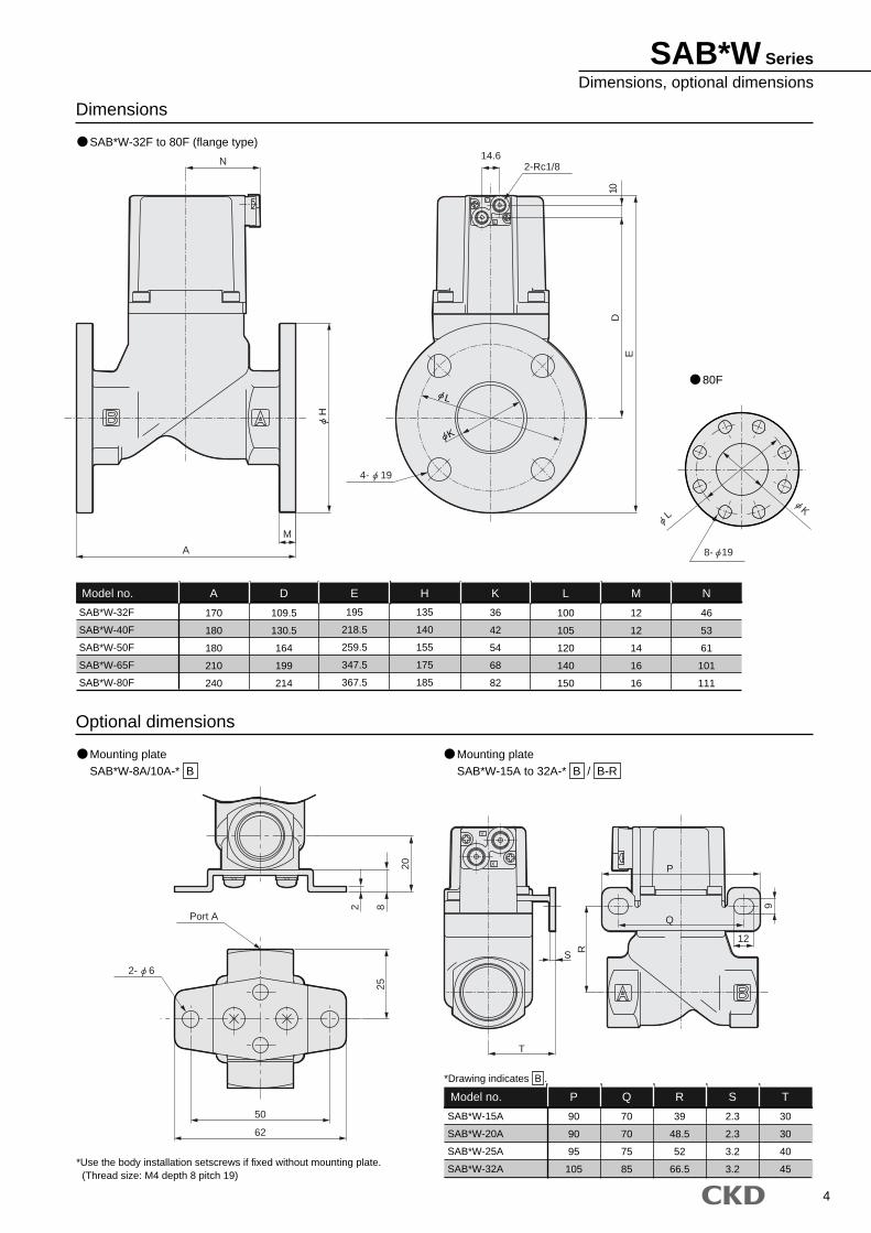
Model no.
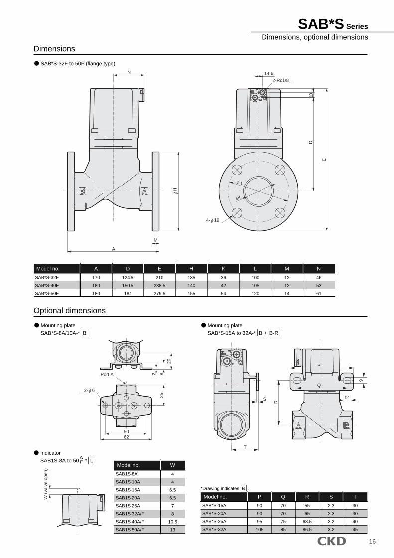
SAB*W-32F
SAB*W-40F
SAB*W-50F
SAB*W-65F
SAB*W-80F
A
170
180
180
210
240
D
109.5
130.5
164
199
214
E
195
218.5
259.5
347.5
367.5
H
135
140
155
175
185
K
36
42
54
68
82
L
100
105
120
140
150
12
12
14
16
16
N
46
53
61
101
111
Model no. M
*Use the body installation setscrews if fixed without mounting plate. (Thread size: M4 depth 8 pitch 19)
SAB*W-32F to 80F (flange type)
Mounting plateSAB*W-8A/10A-* B
Mounting plateSAB*W-15A to 32A-* B / B-R
80F
Y
X
Y
X
N
A
M
E
10D
14.6
Port A
82
20
62
50
25
T
S R
9
12
Q
P
2-Rc1/8
2- 6
4- 19
L
K
H
LK
8- 19
4
SAB*W SeriesDimensions, optional dimensions
JIS symbol
B
A
X
B
A
Y
B
A
X Y
Double acting type
NC (normally closed) type
NO (normally open) type
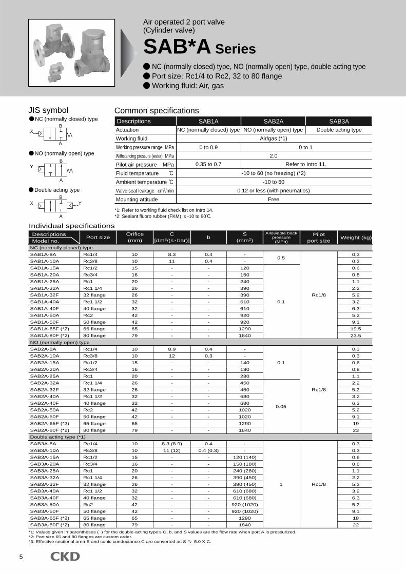
Common specificationsDescriptions SAB1A SAB2A
Air/gas (*1)
2.0
-10 to 60 (no freezing) (*2)
-10 to 60
0.12 or less (with pneumatics)
Free
0 to 0.9
Refer to Intro 11.0.35 to 0.7
0 to 1
NC (normally closed) type NO (normally open) type
SAB3ADouble acting typeActuation
Working fluid
Working pressure range MPa
Withstanding pressure (water) MPa
Pilot air pressure MPa
Fluid temperature
Ambient temperature
Valve seat leakage cm3/min
Mounting attitude
*1: Refer to working fluid check list on Intro 14.*2: Sealant fluoro rubber (FKM) is -10 to 90 .
5
Air operated 2 port valve(Cylinder valve)
SAB*A Series NC (normally closed) type, NO (normally open) type, double acting type Port size: Rc1/4 to Rc2, 32 to 80 flange Working fluid: Air, gas
Individual specificationsDescriptionsModel no.
Port size b Weight (kg)Allowable back
pressure(MPa)
Pilotport size
Rc1/4
Rc3/8
Rc1/2
Rc3/4
Rc1
Rc1 1/4
32 flange
Rc1 1/2
40 flange
Rc2
50 flange
65 flange
80 flange
Rc1/4
Rc3/8
Rc1/2
Rc3/4
Rc1
Rc1 1/4
32 flange
Rc1 1/2
40 flange
Rc2
50 flange
65 flange
80 flange
Rc1/4
Rc3/8
Rc1/2
Rc3/4
Rc1
Rc1 1/4
32 flange
Rc1 1/2
40 flange
Rc2
50 flange
65 flange
80 flange
10
10
15
16
20
26
26
32
32
42
42
65
79
10
10
15
16
20
26
26
32
32
42
42
65
79
10
10
15
16
20
26
26
32
32
42
42
65
79
8.3
11
-
-
-
-
-
-
-
-
-
-
-
8.9
12
-
-
-
-
-
-
-
-
-
-
-
8.3 (8.9)
11 (12)
-
-
-
-
-
-
-
-
-
-
-
0.4
0.4
-
-
-
-
-
-
-
-
-
-
-
0.4
0.3
-
-
-
-
-
-
-
-
-
-
-
0.4
0.4 (0.3)
-
-
-
-
-
-
-
-
-
-
-
-
-
120
150
240
390
390
610
610
920
920
1290
1840
-
-
140
180
280
450
450
680
680
1020
1020
1290
1840
-
-
120 (140)
150 (180)
240 (280)
390 (450)
390 (450)
610 (680)
610 (680)
920 (1020)
920 (1020)
1290
1840
0.3
0.3
0.6
0.8
1.1
2.2
5.2
3.2
6.3
5.2
9.1
19.5
23.5
0.3
0.3
0.6
0.8
1.1
2.2
5.2
3.2
6.3
5.2
9.1
19
23
0.3
0.3
0.6
0.8
1.1
2.2
5.2
3.2
6.3
5.2
9.1
18
22
0.5
0.1
0.1
1 Rc1/8
Rc1/8
0.05
Rc1/8
Orifice(mm)
S(mm2)
NC (normally closed) type
SAB1A-8A
SAB1A-10A
SAB1A-15A
SAB1A-20A
SAB1A-25A
SAB1A-32A
SAB1A-32F
SAB1A-40A
SAB1A-40F
SAB1A-50A
SAB1A-50F
SAB1A-65F (*2)
SAB1A-80F (*2)
NO (normally open) type
SAB2A-8A
SAB2A-10A
SAB2A-15A
SAB2A-20A
SAB2A-25A
SAB2A-32A
SAB2A-32F
SAB2A-40A
SAB2A-40F
SAB2A-50A
SAB2A-50F
SAB2A-65F (*2)
SAB2A-80F (*2)
Double acting type (*1)
SAB3A-8A
SAB3A-10A
SAB3A-15A
SAB3A-20A
SAB3A-25A
SAB3A-32A
SAB3A-32F
SAB3A-40A
SAB3A-40F
SAB3A-50A
SAB3A-50F
SAB3A-65F (*2)
SAB3A-80F (*2)
*1: Values given in parentheses ( ) for the double-acting type's C, b, and S values are the flow rate when port A is pressurized.*2: Port size 65 and 80 flanges are custom order.*3: Effective sectional area S and sonic conductance C are converted as S 5.0 X C.
C[dm3/(s bar)]
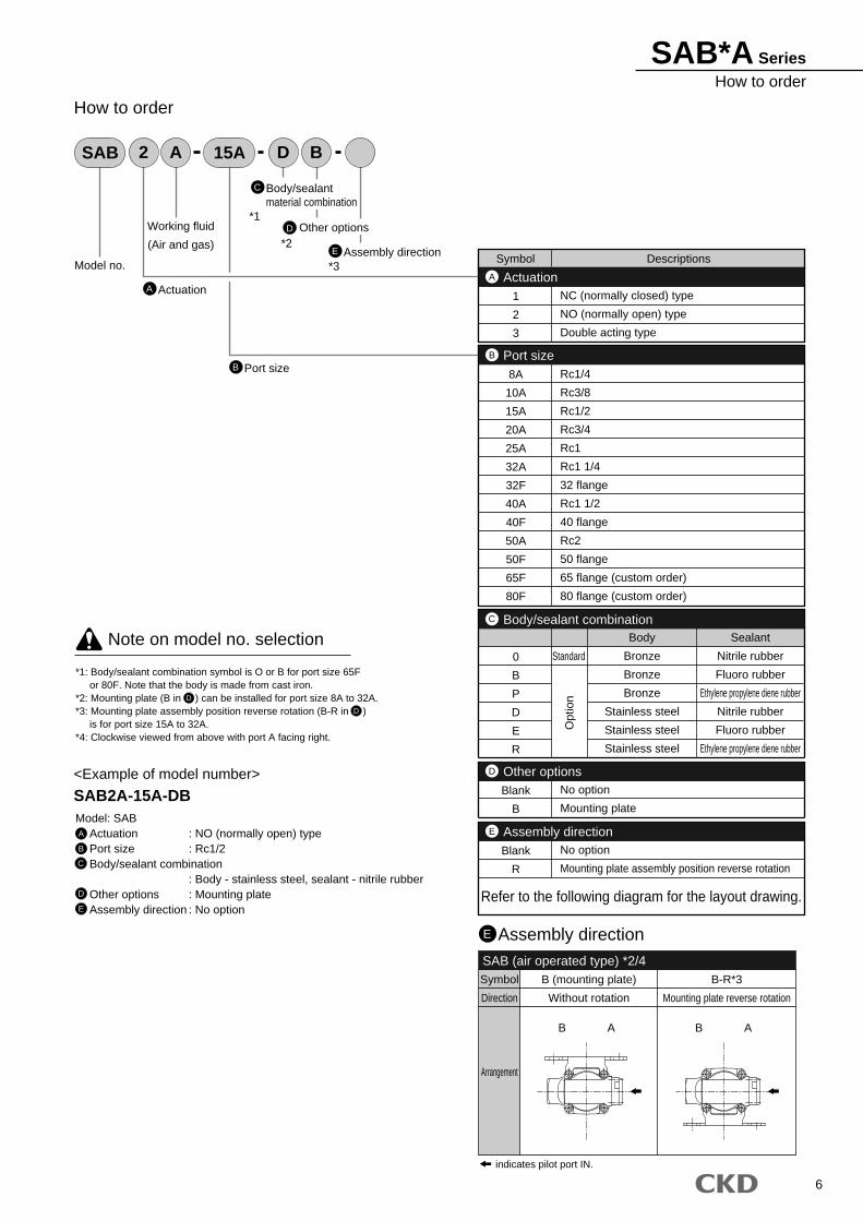
SAB*A SeriesHow to order
6
A
15ASAB 2 A D B
Model no.
Working fluid
(Air and gas)
Actuation
B Port size
C
D
How to order
*1: Body/sealant combination symbol is O or B for port size 65F or 80F. Note that the body is made from cast iron.*2: Mounting plate (B in ) can be installed for port size 8A to 32A.*3: Mounting plate assembly position reverse rotation (B-R in ) is for port size 15A to 32A.*4: Clockwise viewed from above with port A facing right.
Model: SABActuation : NO (normally open) typePort size : Rc1/2Body/sealant combination
: Body - stainless steel, sealant - nitrile rubberOther options : Mounting plateAssembly direction : No option
<Example of model number>
SAB2A-15A-DB
A
B
C
D
E
Note on model no. selection
Body/sealantmaterial combination
E Assembly direction*3
Other options
Assembly directionE
SAB (air operated type) *2/4Symbol
Direction
Arrangement
B (mounting plate)
Without rotation
AB AB
B-R*3
Mounting plate reverse rotation
indicates pilot port IN.
D
D
ActuationA
Blank
B
No option
Mounting plate
Other optionsD
0
B
P
D
E
R
Standard
Body
Bronze
Bronze
Bronze
Stainless steel
Stainless steel
Stainless steel
Sealant
Nitrile rubber
Fluoro rubber
Ethylene propylene diene rubber
Nitrile rubber
Fluoro rubber
Ethylene propylene diene rubber
Body/sealant combinationC
Symbol Descriptions
1
2
3
NC (normally closed) type
NO (normally open) type
Double acting type
Port sizeB
8A
10A
15A
20A
25A
32A
32F
40A
40F
50A
50F
65F
80F
Rc1/4
Rc3/8
Rc1/2
Rc3/4
Rc1
Rc1 1/4
32 flange
Rc1 1/2
40 flange
Rc2
50 flange
65 flange (custom order)
80 flange (custom order)
Opt
ion
Blank
R
No option
Mounting plate assembly position reverse rotation
Assembly directionE
Refer to the following diagram for the layout drawing.
*2
*1
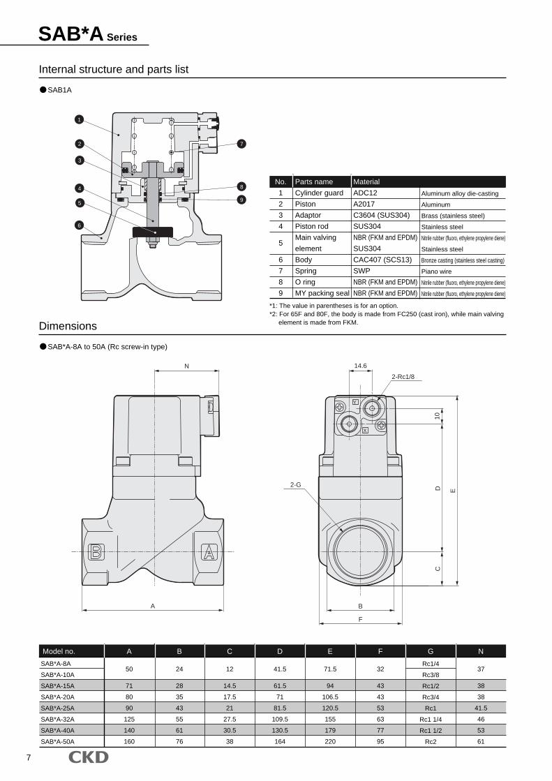
SAB*A Series
7
Internal structure and parts list
Dimensions
SAB*A-8A
SAB*A-10A
SAB*A-15A
SAB*A-20A
SAB*A-25A
SAB*A-32A
SAB*A-40A
SAB*A-50A
A
50
71
80
90
125
140
160
B
24
28
35
43
55
61
76
C
12
14.5
17.5
21
27.5
30.5
38
D
41.5
61.5
71
81.5
109.5
130.5
164
E
71.5
94
106.5
120.5
155
179
220
F
32
43
43
53
63
77
95
Rc1/4
Rc3/8
Rc1/2
Rc3/4
Rc1
Rc1 1/4
Rc1 1/2
Rc2
N
37
38
38
41.5
46
53
61
Model no.
No.
1
2
3
4
5
6
7
8
9
Parts name
Cylinder guard
Piston
Adaptor
Piston rod
Main valving
element
Body
Spring
O ring
MY packing seal
Material
ADC12
A2017
C3604 (SUS304)
SUS304
NBR (FKM and EPDM)
SUS304
CAC407 (SCS13)
SWP
NBR (FKM and EPDM)
NBR (FKM and EPDM)
Aluminum alloy die-casting
Aluminum
Brass (stainless steel)
Stainless steel
Nitrile rubber (fluoro, ethylene propylene diene)
Stainless steel
Bronze casting (stainless steel casting)
Piano wire
Nitrile rubber (fluoro, ethylene propylene diene)
Nitrile rubber (fluoro, ethylene propylene diene)
G
*1: The value in parentheses is for an option.*2: For 65F and 80F, the body is made from FC250 (cast iron), while main valving element is made from FKM.
SAB1A
SAB*A-8A to 50A (Rc screw-in type)
X
Y
CD
10
E
B
F
A
N 14.6
2-Rc1/8
2-G
2
3
4
5
6
7
8
9
1
8
*Drawing indicates B .
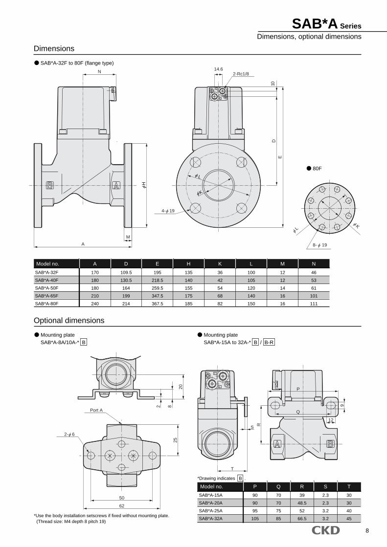
Dimensions
SAB*A-32F
SAB*A-40F
SAB*A-50F
SAB*A-65F
SAB*A-80F
A
170
180
180
210
240
D
109.5
130.5
164
199
214
E
195
218.5
259.5
347.5
367.5
H
135
140
155
175
185
K
36
42
54
68
82
L
100
105
120
140
150
12
12
14
16
16
N
46
53
61
101
111
Model no. M
Optional dimensions
SAB*A-15A
SAB*A-20A
SAB*A-25A
SAB*A-32A
P
90
90
95
105
Q
70
70
75
85
R
39
48.5
52
66.5
S
2.3
2.3
3.2
3.2
T
30
30
40
45
Model no.
*Use the body installation setscrews if fixed without mounting plate. (Thread size: M4 depth 8 pitch 19)
SAB*A-32F to 80F (flange type)
Mounting plateSAB*A-8A/10A-* B
Mounting plateSAB*A-15A to 32A-* B / B-R
80F
Y
X
Y
X
N
A
M
E
10
14.6
82
20
62
50
25
T
S R
9
12
Q
P
D
Port A
2-Rc1/8
H
4- 19
L
K
2- 6
LK
8- 19
SAB*A SeriesDimensions, optional dimensions
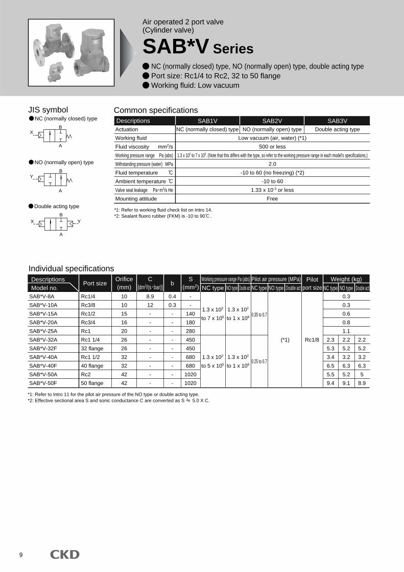
9
Air operated 2 port valve(Cylinder valve)
SAB*V Series NC (normally closed) type, NO (normally open) type, double acting type Port size: Rc1/4 to Rc2, 32 to 50 flange Working fluid: Low vacuum
JIS symbol
B
A
A
X
BY
B
A
X Y
Double acting type
NC (normally closed) type
NO (normally open) type
Common specificationsDescriptions SAB1V SAB2V
Low vacuum (air, water) (*1)
500 or less
1.3 x 10² to 7 x 10⁵. (Note that this differs with the type, so refer to the working pressure range in each model's specifications.)
2.0
-10 to 60 (no freezing) (*2)
-10 to 60
1.33 x 10⁻³ or less
Free
NC (normally closed) type NO (normally open) type
SAB3VDouble acting type
Individual specificationsDescriptionsModel no.
Port size bWeight (kg)Pilot
port size NC type NO type Double actSAB*V-8A
SAB*V-10A
SAB*V-15A
SAB*V-20A
SAB*V-25A
SAB*V-32A
SAB*V-32F
SAB*V-40A
SAB*V-40F
SAB*V-50A
SAB*V-50F
Rc1/4
Rc3/8
Rc1/2
Rc3/4
Rc1
Rc1 1/4
32 flange
Rc1 1/2
40 flange
Rc2
50 flange
10
10
15
16
20
26
26
32
32
42
42
8.9
12
-
-
-
-
-
-
-
-
-
0.4
0.3
-
-
-
-
-
-
-
-
-
-
-
140
180
280
450
450
680
680
1020
1020
Rc1/8
0.3
0.3
0.6
0.8
1.1
2.2
5.2
3.2
6.3
5.2
9.1
2.3
5.3
3.4
6.5
5.5
9.4
2.2
5.2
3.2
6.3
5
8.9
(*1)
Orifice(mm)
S(mm2)
Working pressure range Pa (abs)NC type NO type Double act
Pilot air pressure (MPa)NC type NO type Double act
0.35 to 0.71.3 x 102
to 1 x 10⁶
1.3 x 10²
to 7 x 10⁵
0.25 to 0.71.3 x 102
to 1 x 10⁶
1.3 x 10²
to 5 x 10⁵
Actuation
Working fluid
Fluid viscosity mm2/s
Working pressure range Pa (abs)
Withstanding pressure (water) MPa
Fluid temperature
Ambient temperature
Valve seat leakage Pa m3/s He
Mounting attitude
*1: Refer to working fluid check list on Intro 14.*2: Sealant fluoro rubber (FKM) is -10 to 90 .
*1: Refer to Intro 11 for the pilot air pressure of the NO type or double acting type.*2: Effective sectional area S and sonic conductance C are converted as S 5.0 X C.
C[dm3/(s bar)]
10
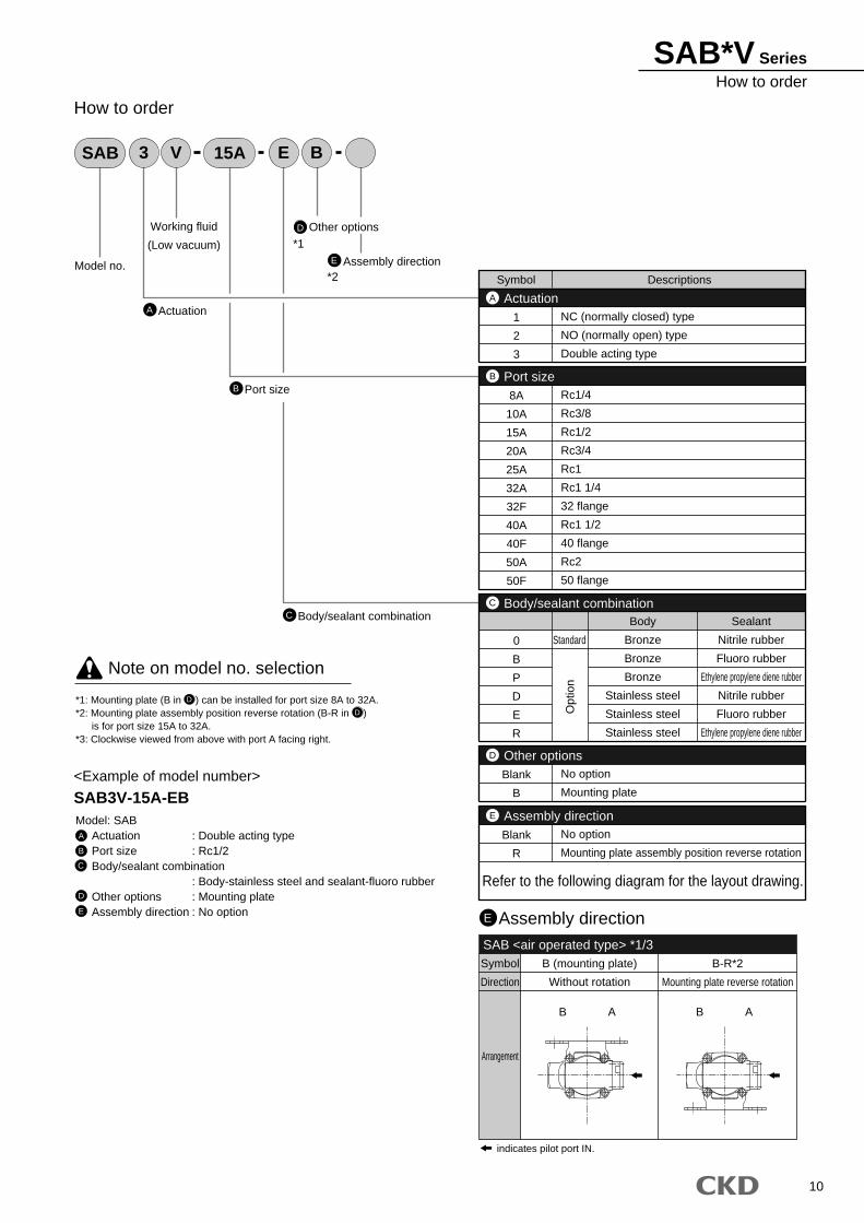
SAB*V SeriesHow to order
A
15ASAB 3 V E B
Model no.
Working fluid
(Low vacuum)
Actuation
E Assembly direction
B Port size
C Body/sealant combination
D Other options
How to order
*1: Mounting plate (B in ) can be installed for port size 8A to 32A.*2: Mounting plate assembly position reverse rotation (B-R in ) is for port size 15A to 32A.*3: Clockwise viewed from above with port A facing right.
Model: SABActuation : Double acting typePort size : Rc1/2Body/sealant combination
: Body-stainless steel and sealant-fluoro rubberOther options : Mounting plateAssembly direction : No option
<Example of model number>
SAB3V-15A-EB
A
B
C
D
E
D
D
Note on model no. selection
Assembly directionE
SAB <air operated type> *1/3Symbol
Direction
Arrangement
B (mounting plate)
Without rotation
AB AB
B-R*2
Mounting plate reverse rotation
indicates pilot port IN.
ActuationA
Blank
B
No option
Mounting plate
Other optionsD
0
B
P
D
E
R
Standard
Body
Bronze
Bronze
Bronze
Stainless steel
Stainless steel
Stainless steel
Sealant
Nitrile rubber
Fluoro rubber
Ethylene propylene diene rubber
Nitrile rubber
Fluoro rubber
Ethylene propylene diene rubber
Body/sealant combinationC
Symbol Descriptions
1
2
3
NC (normally closed) type
NO (normally open) type
Double acting type
Port sizeB
8A
10A
15A
20A
25A
32A
32F
40A
40F
50A
50F
Rc1/4
Rc3/8
Rc1/2
Rc3/4
Rc1
Rc1 1/4
32 flange
Rc1 1/2
40 flange
Rc2
50 flangeO
ptio
n
Blank
R
No option
Mounting plate assembly position reverse rotation
Assembly directionE
Refer to the following diagram for the layout drawing.
*1
*2

11
SAB*V Series
Internal structure and parts list
SAB1 V
SAB*V-8A to 50A (Rc screw in type)
Dimensions
SAB*V-8A
SAB*V-10A
SAB*V-15A
SAB*V-20A
SAB*V-25A
SAB*V-32A
SAB*V-40A
SAB*V-50A
A
50
71
80
90
125
140
160
B
24
28
35
43
55
61
76
C
12
14.5
17.5
21
27.5
30.5
38
D
41.5
61.5
71
81.5
109.5
130.5
164
E
71.5
94
106.5
120.5
155
179
220
F
32
43
43
53
63
77
95
Rc1/4
Rc3/8
Rc1/2
Rc3/4
Rc1
Rc1 1/4
Rc1 1/2
Rc2
N
37
38
38
41.5
46
53
61
Model no.
No.
1
2
3
4
5
6
7
8
9
Parts name
Cylinder guard
Piston
Adaptor
Piston rod
Main valving
element
Body
Spring
O ring
MY packing seal
Material
ADC12
A2017
C3604 (SUS304)
SUS304
NBR (FKM and EPDM)
SUS304
CAC407 (SCS13)
SWP
NBR (FKM and EPDM)
NBR (FKM and EPDM)
Aluminum alloy die-casting
Aluminum
Brass (stainless steel)
Stainless steel
Nitrile rubber (fluoro, ethylene propylene diene)
Stainless steel
Bronze casting (stainless steel casting)
Piano wire
Nitrile rubber (fluoro, ethylene propylene diene)
Nitrile rubber (fluoro, ethylene propylene diene)
G
The value in parentheses is for an option.
X
Y
CD
10
E
B
F
A
N 14.6
2-Rc1/8
2-G
2
3
4
5
6
7
8
9
1

12
SAB*V SeriesDimensions, optional dimensions
*Drawing indicates B .
Dimensions
SAB*V-32F
SAB*V-40F
SAB*V-50F
A
170
180
180
D
109.5
130.5
164
E
195
218.5
259.5
H
135
140
155
K
36
42
54
L
100
105
120
12
12
14
N
46
53
61
Model no. M
Optional dimensions
SAB*V-15A
SAB*V-20A
SAB*V-25A
SAB*V-32A
P
90
90
95
105
Q
70
70
75
85
R
39
48.5
52
66.5
S
2.3
2.3
3.2
3.2
T
30
30
40
45
Model no.
*Use the body installation setscrews if fixed without mounting plate. (Thread size: M4 depth 8 pitch 19)
SAB*V-32F to 50F (flange type)
Mounting plateSAB*V-8A/10A-* B
Mounting plateSAB*V-15A to 32A-* B / B-R
Y
X
Y
X
N
A
M
E
10
14.6
82
20
T
S
R
9
12
Q
P
D
62
50
25
Port A
2-Rc1/8
H
4- 19
L
K
2- 6
13
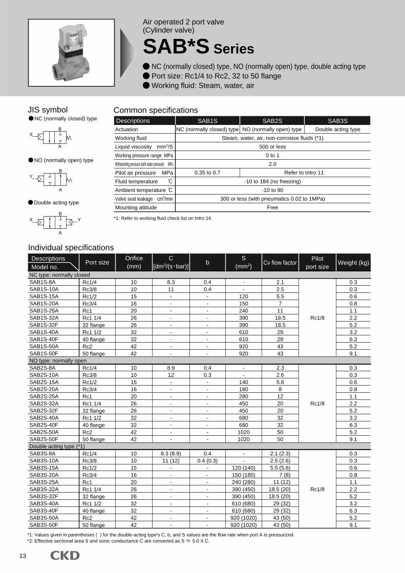
Air operated 2 port valve(Cylinder valve)
SAB*S Series NC (normally closed) type, NO (normally open) type, double acting type Port size: Rc1/4 to Rc2, 32 to 50 flange Working fluid: Steam, water, air
JIS symbol
B
A
X
B
A
Y
B
A
X Y
Double acting type
NC (normally closed) type
NO (normally open) type
Common specificationsDescriptions SAB1S SAB2S
Steam, water, air, non-corrosive fluids (*1)
500 or less
0 to 1
2.0
-10 to 184 (no freezing)
-10 to 90
300 or less (with pneumatics 0.02 to 1MPa)
Free
Refer to Intro 11.0.35 to 0.7
NC (normally closed) type NO (normally open) type
SAB3SDouble acting type
*1: Refer to working fluid check list on Intro 14.
Individual specificationsDescriptionsModel no.
Port size b Weight (kg)Cv flow factorPilot
port size
Rc1/4Rc3/8Rc1/2Rc3/4Rc1Rc1 1/432 flangeRc1 1/240 flangeRc250 flange
Rc1/4Rc3/8Rc1/2Rc3/4Rc1Rc1 1/432 flangeRc1 1/240 flangeRc250 flange
Rc1/4Rc3/8Rc1/2Rc3/4Rc1Rc1 1/432 flangeRc1 1/240 flangeRc250 flange
1010151620262632324242
1010151620262632324242
1010151620262632324242
8.311---------
8.912---------
8.3 (8.9)11 (12)
---------
0.40.4---------
0.40.3---------
0.40.4 (0.3)
---------
--
120150240390390610610920920
--
140180280450450680680
10201020
--
120 (140)150 (180)240 (280)390 (450)390 (450)610 (680)610 (680)
920 (1020)920 (1020)
Rc1/8
Rc1/8
Rc1/8
Orifice(mm)
S(mm2)
NC type: normally closedSAB1S-8ASAB1S-10ASAB1S-15ASAB1S-20ASAB1S-25ASAB1S-32ASAB1S-32FSAB1S-40ASAB1S-40FSAB1S-50ASAB1S-50FNO type: normally openSAB2S-8ASAB2S-10ASAB2S-15ASAB2S-20ASAB2S-25ASAB2S-32ASAB2S-32FSAB2S-40ASAB2S-40FSAB2S-50ASAB2S-50FDouble acting type (*1)SAB3S-8ASAB3S-10ASAB3S-15ASAB3S-20ASAB3S-25ASAB3S-32ASAB3S-32FSAB3S-40ASAB3S-40FSAB3S-50ASAB3S-50F
2.32.65.68
12202032325050
2.12.55.57
1118.518.529294343
0.30.30.60.81.12.25.23.26.35.29.1
0.30.30.60.81.12.25.23.26.35.29.1
0.30.30.60.81.12.25.23.26.35.29.1
2.1 (2.3)2.5 (2.6)5.5 (5.6)
7 (8)11 (12)
18.5 (20)18.5 (20)
29 (32)29 (32)43 (50)43 (50)
Actuation
Working fluid
Liquid viscosity mm2/S
Working pressure range MPa
Withstanding pressure (with water pressure) MPa
Pilot air pressure MPa
Fluid temperature
Ambient temperature
Valve seat leakage cm3/min
Mounting attitude
*1: Values given in parentheses ( ) for the double-acting type's C, b, and S values are the flow rate when port A is pressurized.*2: Effective sectional area S and sonic conductance C are converted as S 5.0 X C.
C[dm3/(s bar)]
14
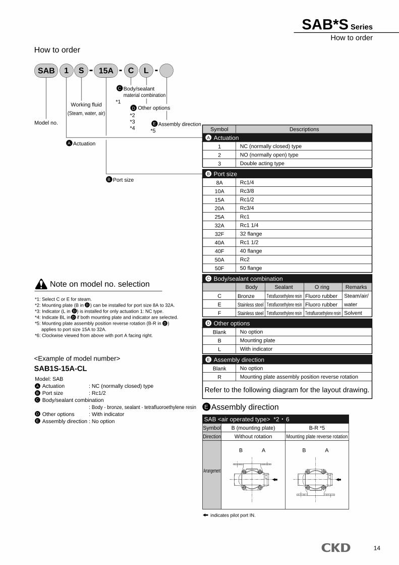
SAB*S SeriesHow to order
A
15ASAB 1 S C L
Model no.
Working fluid
(Steam, water, air)
Actuation
B Port size
E Assembly direction
C
D Other options
How to order
Model: SABActuation : NC (normally closed) typePort size : Rc1/2Body/sealant combination
: Body - bronze, sealant - tetrafluoroethylene resinOther options : With indicatorAssembly direction : No option
<Example of model number>
SAB1S-15A-CL
A
B
C
D
E
*1: Select C or E for steam.*2: Mounting plate (B in ) can be installed for port size 8A to 32A.*3: Indicator (L in ) is installed for only actuation 1: NC type.*4: Indicate BL in if both mounting plate and indicator are selected.*5: Mounting plate assembly position reverse rotation (B-R in ) applies to port size 15A to 32A.*6: Clockwise viewed from above with port A facing right.
D
D
D
D
Note on model no. selection
Body/sealantmaterial combination
Assembly directionE
Symbol
Direction
Arrangement
B (mounting plate)
Without rotation
AB AB
B-R *5
Mounting plate reverse rotation
indicates pilot port IN.
SAB <air operated type> *2 6
ActuationA
Blank
B
L
No option
Mounting plate
With indicator
Other optionsD
C
E
F
Body Sealant O ring Remarks
Body/sealant combinationC
Symbol Descriptions
1
2
3
NC (normally closed) type
NO (normally open) type
Double acting type
Port sizeB
8A
10A
15A
20A
25A
32A
32F
40A
40F
50A
50F
Rc1/4
Rc3/8
Rc1/2
Rc3/4
Rc1
Rc1 1/4
32 flange
Rc1 1/2
40 flange
Rc2
50 flange
Blank
R
No option
Mounting plate assembly position reverse rotation
Assembly directionE
Refer to the following diagram for the layout drawing.
*2*3*4
*1
*5
Bronze
Stainless steel
Stainless steel
Tetrafluoroethylene resin
Tetrafluoroethylene resin
Tetrafluoroethylene resin
Fluoro rubber
Fluoro rubber
Tetrafluoroethylene resin
Steam/air/
water
Solvent
15
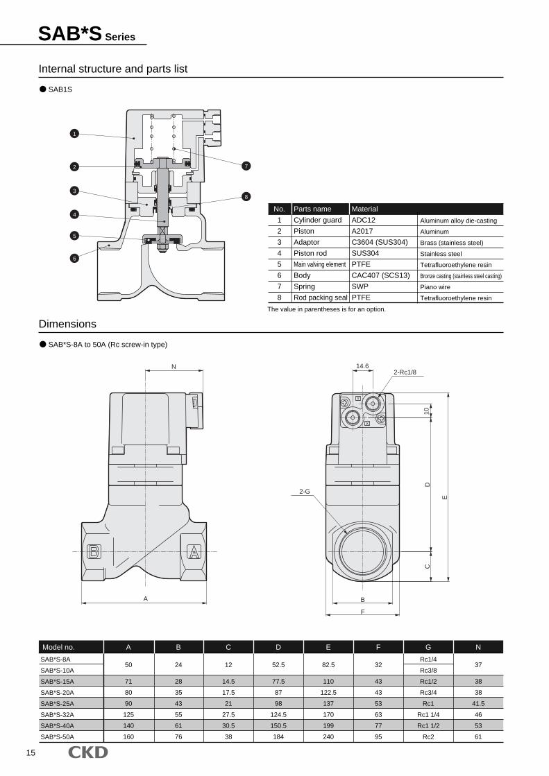
SAB*S Series
Internal structure and parts list
Dimensions
SAB*S-8A
SAB*S-10A
SAB*S-15A
SAB*S-20A
SAB*S-25A
SAB*S-32A
SAB*S-40A
SAB*S-50A
A
50
71
80
90
125
140
160
B
24
28
35
43
55
61
76
C
12
14.5
17.5
21
27.5
30.5
38
D
52.5
77.5
87
98
124.5
150.5
184
E
82.5
110
122.5
137
170
199
240
F
32
43
43
53
63
77
95
Rc1/4
Rc3/8
Rc1/2
Rc3/4
Rc1
Rc1 1/4
Rc1 1/2
Rc2
N
37
38
38
41.5
46
53
61
Model no. G
No.
1
2
3
4
5
6
7
8
Parts name
Cylinder guard
Piston
Adaptor
Piston rod
Main valving element
Body
Spring
Rod packing seal
Material
ADC12
A2017
C3604 (SUS304)
SUS304
PTFE
CAC407 (SCS13)
SWP
PTFE
Aluminum alloy die-casting
Aluminum
Brass (stainless steel)
Stainless steel
Tetrafluoroethylene resin
Bronze casting (stainless steel casting)
Piano wire
Tetrafluoroethylene resin
SAB1S
SAB*S-8A to 50A (Rc screw-in type)
1
2
3
4
5
6
7
8
F
E
DC
B
N
A
14.6
10
Y
X
2-Rc1/8
The value in parentheses is for an option.
2-G
16
SAB*S SeriesDimensions, optional dimensions
Dimensions
Optional dimensions
SAB*S-32F
SAB*S-40F
SAB*S-50F
A
170
180
180
D
124.5
150.5
184
E
210
238.5
279.5
H
135
140
155
K
36
42
54
L
100
105
120
12
12
14
N
46
53
61
Model no. M
SAB*S-15A
SAB*S-20A
SAB*S-25A
SAB*S-32A
P
90
90
95
105
Q
70
70
75
85
R
55
65
68.5
86.5
S
2.3
2.3
3.2
3.2
T
30
30
40
45
Model no.
SAB1S-8A
SAB1S-10A
SAB1S-15A
SAB1S-20A
SAB1S-25A
SAB1S-32A/F
SAB1S-40A/F
SAB1S-50A/F
W
4
4
6.5
6.5
7
8
10.5
13
Model no.
AF
*Drawing indicates B .
SAB*S-32F to 50F (flange type)
Mounting plateSAB*S-8A/10A-* B
Mounting plateSAB*S-15A to 32A-* B / B-R
IndicatorSAB1S-8A to 50 -* L
Y
X
Y
X
X
Y
A
M
E
D10
N 14.6
P
T
S
Q
R
12
9
W (
valv
e op
en)
Port A 82
20
6250
25
2-Rc1/8
H
L
K
4- 19
2- 6
17
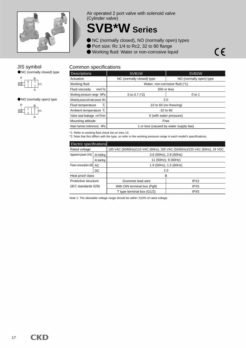
Air operated 2 port valve with solenoid valve(Cylinder valve)
SVB*W Series NC (normally closed), NO (normally open) types Port size: Rc 1/4 to Rc2, 32 to 80 flange Working fluid: Water or non-corrosive liquid
B
A
P
B
A
P
JIS symbolNC (normally closed) type
NO (normally open) type
Common specificationsDescriptions SVB1W
Water, non-corrosive fluid (*1)
500 or less
2.0
-10 to 60 (no freezing)
-10 to 60
0 (with water pressure)
Free
1 or less (caused by water supply law)
NC (normally closed) type
SVB2WNO (normally open) type
Grommet lead wire
With DIN terminal box (Pg9)
T type terminal box (G1/2)
IPX2
IPX5
IPX5
*1: Refer to working fluid check list on Intro 14.*2: Note that this differs with the type, so refer to the working pressure range in each model's specifications.
Electric specificationsRated voltage
Apparent power (VA)
Power consumption (W)
Heat proof class
Protective structure
(IEC standards 529)
100 VAC (50/60Hz)/110 VAC (60Hz), 200 VAC (50/60Hz)/220 VAC (60Hz), 24 VDC
3.6 (50Hz), 2.8 (60Hz)
11 (50Hz), 9 (60Hz)
1.9 (50Hz), 1.5 (60Hz)
2.0
B
At holding
At starting
AC
DC
0 to 0.7 (*2) 0 to 1
Actuation
Working fluid
Fluid viscosity mm2/s
Working pressure range MPa
Withstanding pressure (with water pressure) MPa
Fluid temperature
Ambient temperature
Valve seat leakage cm3/min
Mounting attitude
Water hammer (references) MPa
Note 1: The allowable voltage range should be within 10% of rated voltage.
18
SVB*W SeriesSpecifications
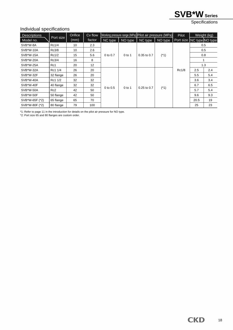
*1: Refer to page 11 in the introduction for details on the pilot air pressure for NO type. *2: Port size 65 and 80 flanges are custom order.
Individual specificationsDescriptionsModel no.
Port sizeWeight (kg)Pilot
Port size NC type NO typeNC type NO type NC type NO typeSVB*W-8A
SVB*W-10A
SVB*W-15A
SVB*W-20A
SVB*W-25A
SVB*W-32A
SVB*W-32F
SVB*W-40A
SVB*W-40F
SVB*W-50A
SVB*W-50F
SVB*W-65F (*2)
SVB*W-80F (*2)
Rc1/4
Rc3/8
Rc1/2
Rc3/4
Rc1
Rc1 1/4
32 flange
Rc1 1/2
40 flange
Rc2
50 flange
65 flange
80 flange
10
10
15
16
20
26
26
32
32
42
42
65
79
2.3
2.6
5.6
8
12
20
20
32
32
50
50
70
100
0 to 0.7
0 to 0.5
0 to 1
0 to 1
(*1)
(*1)
0.35 to 0.7
0.25 to 0.7
Rc1/8 2.5
5.5
3.6
6.7
5.7
9.6
20.5
25
0.5
0.5
0.8
1
1.3
2.4
5.4
3.4
6.5
5.4
9.3
19
23
Orifice(mm)
Working pressure range (MPa) Pilot air pressure (MPa)Cv flowfactor
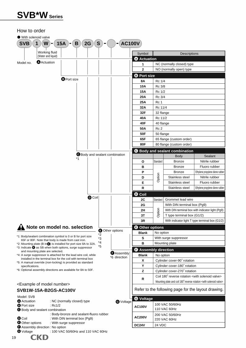
*1: Body/sealant combination symbol is 0 or B for port size 65F or 80F. Note that body is made from cast iron.
*2: Mounting plate (B in ) is installed for port size 8A to 32A.*3: Indicate as SB when both options, surge suppressor
and mounting plate are selected.*4: A surge suppressor is attached for the lead wire coil, while
installed in the terminal box for the coil with terminal box*5: A manual override (non-locking) is provided as standard
specifications.*6: Optional assembly directions are available for 8A to 50F.
15A 2GSVB AC100V1 W B S
Model no.
Working fluid(Water and liquid)
Actuation
F Assembly direction
B Port size
C Body and sealant combination
D Coil
E Other options
G Voltage
How to order
Model: SVBActuation : NC (normally closed) typePort size : Rc1/2Body and sealant combination
: Body-bronze and sealant-fluoro rubberCoil : With DIN terminal box (Pg9)Other options : With surge suppressorAssembly direction : No optionVoltage : 100 VAC 50/60Hz and 110 VAC 60Hz
<Example of model number>
SVB1W-15A-B2GS-AC100V
A
B
C
D
E
F
G
E
E
Note on model no. selection
With solenoid valve
AActuationA
2C
2G
2H
3T
3R
Grommet lead wire
With DIN terminal box (Pg9)
With DIN terminal box with indicator light (Pg9)
T type terminal box (G1/2)
With indicator light T type terminal box (G1/2)
D
O
B
P
D
E
R
Standard
Body
Bronze
Bronze
Bronze
Stainless steel
Stainless steel
Stainless steel
Sealant
Nitrile rubber
Fluoro rubber
Ethylene propylene diene rubber
Nitrile rubber
Fluoro rubber
Ethylene propylene diene rubber
Body and sealant combinationC
Symbol Descriptions
1
2
NC (normally closed) type
NO (normally open) type
Port size
Coil
B
8A
10A
15A
20A
25A
32A
32F
40A
40F
50A
50F
65F
80F
Rc 1/4
Rc 3/8
Rc 1/2
Rc 3/4
Rc 1
Rc 11/4
32 flange
Rc 11/2
40 flange
Rc 2
50 flange
65 flange (custom order)
80 flange (custom order)
Assembly directionF
Blank
X
Y
Z
R
No option
Cylinder cover-90 rotation
Cylinder cover-180 rotation
Cylinder cover-270 rotation
Coil 180 reverse rotation <with solenoid valve>
Mounting plate and coil 180 reverse rotation <with solenoid valve>
Refer to the following page for the layout drawing.
Opt
ion
Standard
Opt
ion
Blank
S
B
No option
With surge suppressor
Mounting plate
Other optionsE
AC100V
AC200V
DC24V
100 VAC 50/60Hz110 VAC 60Hz
200 VAC 50/60Hz220 VAC 60Hz
24 VDC
VoltageG
*2*3*4*5
*1
*6
19
SVB*W Series
20
SVB*W SeriesHow to order
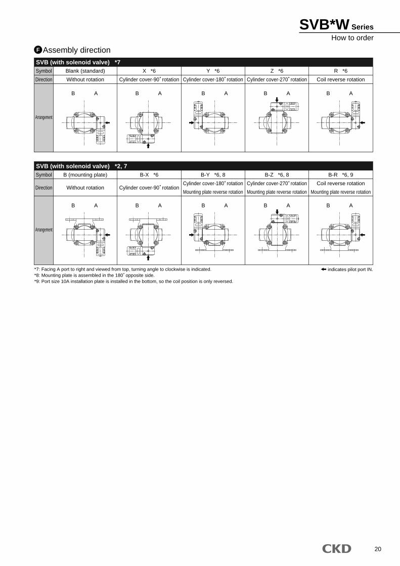
Assembly directionF
SVB (with solenoid valve) *7Symbol
Direction
Arrangement
Blank (standard)
Without rotation
X *6
Cylinder cover-90 rotation
Y *6
Cylinder cover-180 rotation
Z *6
Cylinder cover-270 rotation
R *6
Coil reverse rotation
SVB (with solenoid valve) *2, 7Symbol
Direction
Arrangement
B (mounting plate)
Without rotation
B-X *6
Cylinder cover-90 rotation
B-Y *6, 8
Cylinder cover-180 rotation
Mounting plate reverse rotation
B-Z *6, 8
Cylinder cover-270 rotation
Mounting plate reverse rotation
B-R *6, 9
Coil reverse rotation
Mounting plate reverse rotation
AB AB AB ABAB
AB AB AB ABAB
*7: Facing A port to right and viewed from top, turning angle to clockwise is indicated.*8: Mounting plate is assembled in the 180 opposite side.*9: Port size 10A installation plate is installed in the bottom, so the coil position is only reversed.
indicates pilot port IN.
21
SVB*W Series
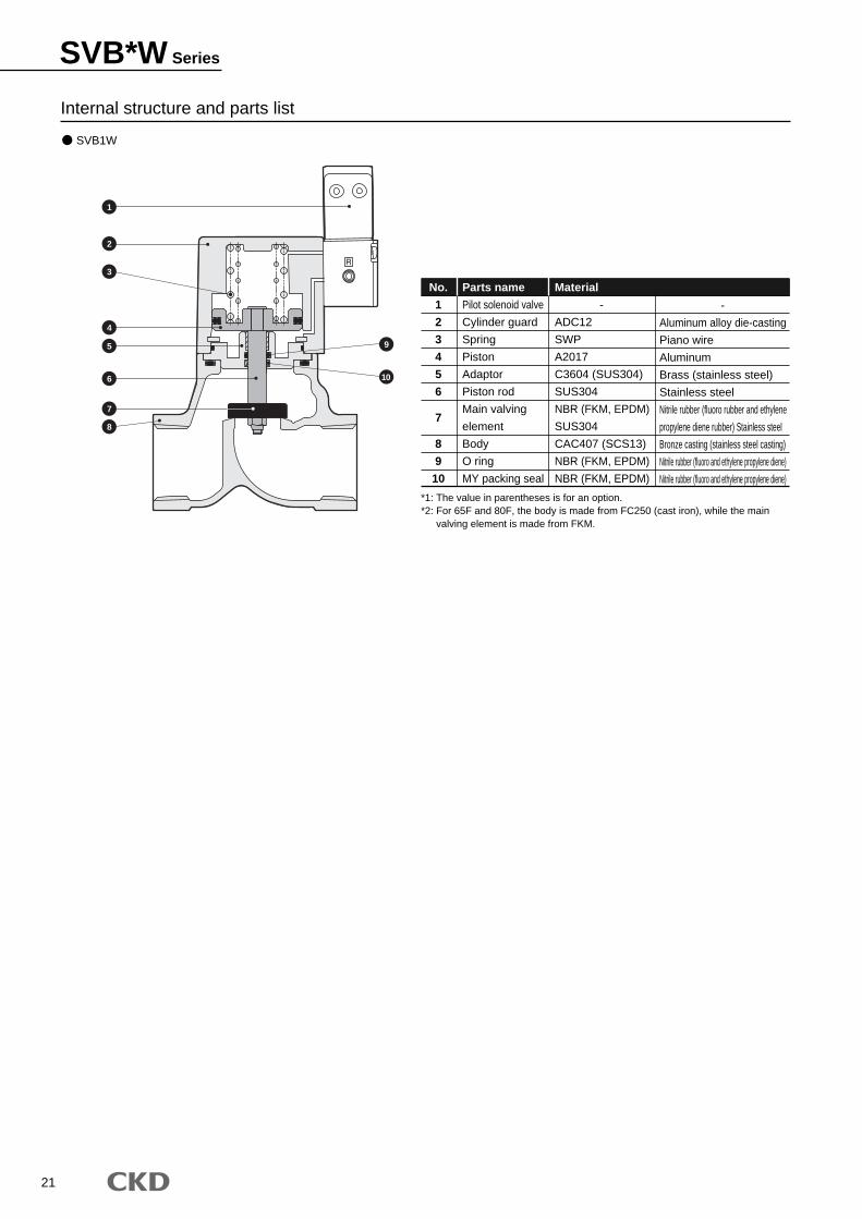
SVB1W
Internal structure and parts list
No.
1
2
3
4
5
6
7
8
9
10
Parts name
Pilot solenoid valve
Cylinder guard
Spring
Piston
Adaptor
Piston rod
Main valving
element
Body
O ring
MY packing seal
Material
-
ADC12
SWP
A2017
C3604 (SUS304)
SUS304
NBR (FKM, EPDM)
SUS304
CAC407 (SCS13)
NBR (FKM, EPDM)
NBR (FKM, EPDM)
-
Aluminum alloy die-casting
Piano wire
Aluminum
Brass (stainless steel)
Stainless steel
Nitrile rubber (fluoro rubber and ethylene
propylene diene rubber) Stainless steel
Bronze casting (stainless steel casting)
Nitrile rubber (fluoro and ethylene propylene diene)
Nitrile rubber (fluoro and ethylene propylene diene)
*1: The value in parentheses is for an option.*2: For 65F and 80F, the body is made from FC250 (cast iron), while the main
valving element is made from FKM.
1
2
3
4
5 9
106
7
8
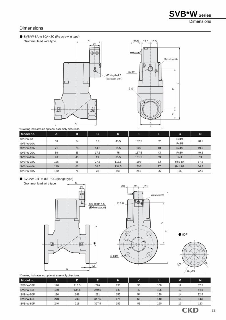
22
SVB*W SeriesDimensions
SVB*W-32F to 80F-*2C (flange type)
Grommet lead wire type
SVB*W-32F
SVB*W-40F
SVB*W-50F
SVB*W-65F
SVB*W-80F
A D E H K L N
57.5
64.5
72.5
113
123
Model no. M
SVB*W-8A to 50A-*2C (Rc screw in type)
Grommet lead wire type
Dimensions
SVB*W-8A
SVB*W-10A
SVB*W-15A
SVB*W-20A
SVB*W-25A
SVB*W-32A
SVB*W-40A
SVB*W-50A
A
50
71
80
90
125
140
160
B
24
28
35
43
55
61
76
C
12
14.5
17.5
21
27.5
30.5
38
D
45.5
65.5
75
85.5
113.5
134.5
168
E
102.5
125
137.5
151.5
186
210
251
F
32
43
43
53
63
77
95
Rc1/4
Rc3/8
Rc1/2
Rc3/4
Rc1
Rc1 1/4
Rc1 1/2
Rc2
N
48.5
49.5
49.5
53
57.5
64.5
72.5
Model no. G
170
180
180
210
240
113.5
134.5
168
203
218
226
249.5
291
347.5
367.5
135
140
155
175
185
36
42
54
68
82
100
105
120
140
150
12
12
14
16
16
*Drawing indicates no optional assembly directions.
*Drawing indicates no optional assembly directions.
P
22N
M5 depth 4.5(Exhaust port)
H
MA
E
K
L
D
15.519.5(300)
Rc1/8
4- 19
8- 19
KL
80F
Manual override
Manual override
N
A
22
Rc1/8
2-G D
E
C
BF
(300) 19.5 15.5
M5 depth 4.5(Exhaust port)
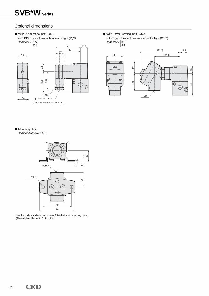
23
SVB*W Series
Optional dimensions
2G2H
3T3R
*Use the body installation setscrews if fixed without mounting plate. (Thread size: M4 depth 8 pitch 19)
Mounting plate
SVB*W-8A/10A-** B
With DIN terminal box (Pg9),
with DIN terminal box with indicator light (Pg9)
SVB*W-*-*
With T type terminal box (G1/2),
with T type terminal box with indicator light (G1/2)
SVB*W-*-*
P
P
Port A 82
20
62
50
25
15.5
3626
4616
G1/2
(54.5)
(85.5)
3522
24
15.5
18
44
53(3
8)
44.5
Applicable cable
Pg9
(Outer diameter 4.5 to 7)
2- 6
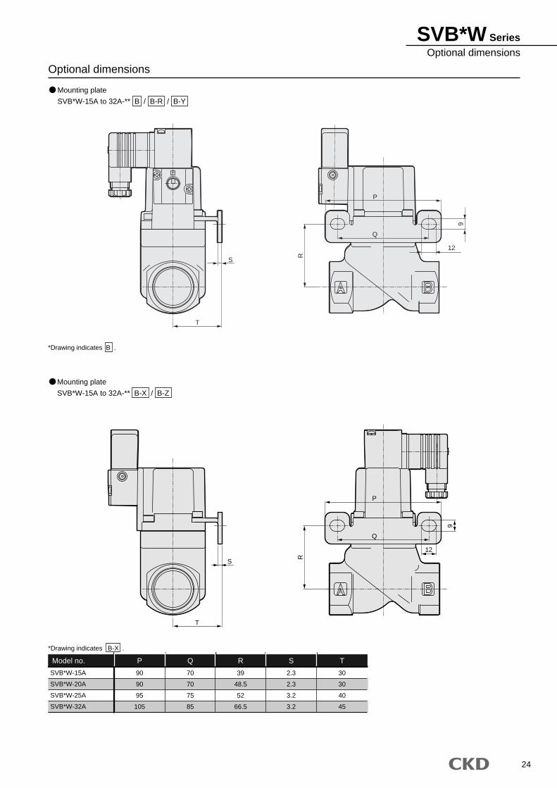
24
SVB*W SeriesOptional dimensions
Optional dimensions
Mounting plate
SVB*W-15A to 32A-** B / B-R / B-Y
Mounting plate
SVB*W-15A to 32A-** B-X / B-Z
*Drawing indicates B .
SVB*W-15A
SVB*W-20A
SVB*W-25A
SVB*W-32A
P
90
90
95
105
Q
70
70
75
85
R
39
48.5
52
66.5
S
2.3
2.3
3.2
3.2
T
30
30
40
45
Model no.
*Drawing indicates B-X .
P
S
T
R
9
12
Q
P
T
S
P
Q
12
R
9
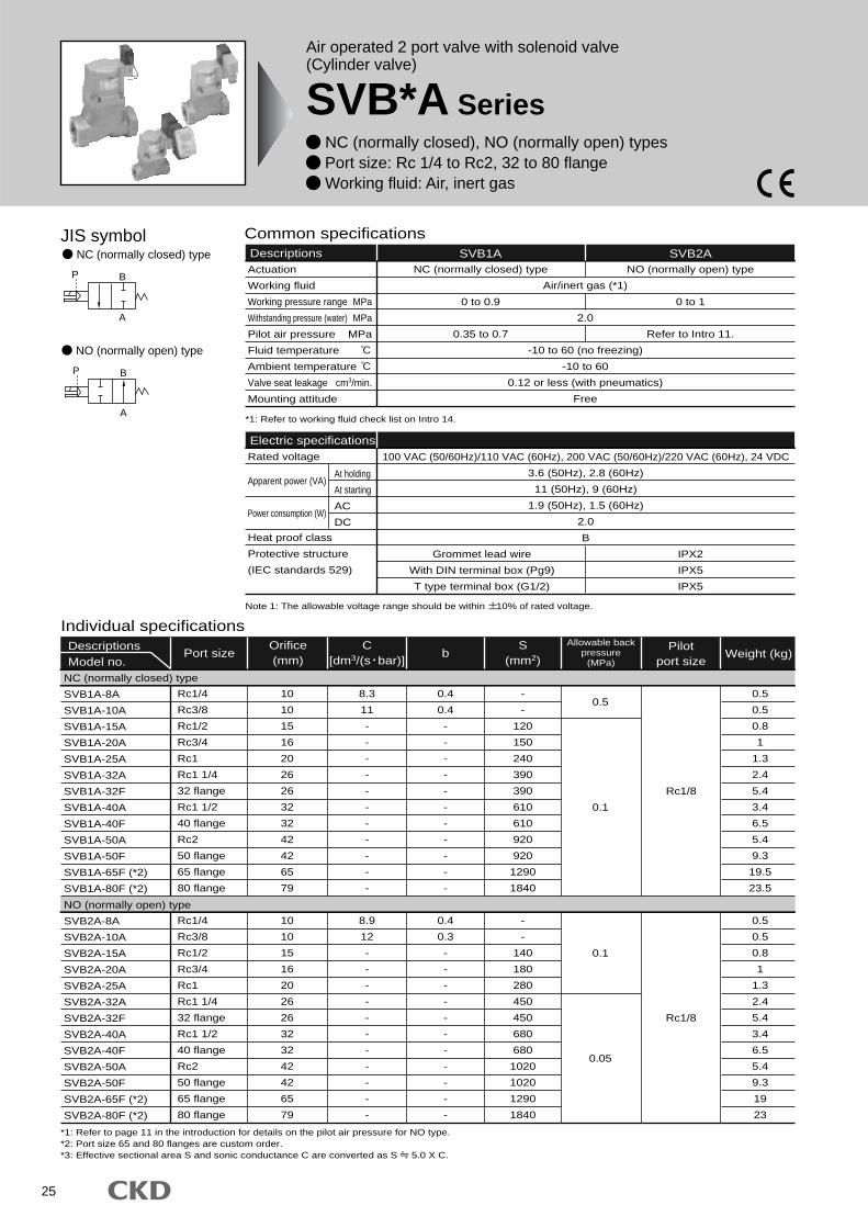
25
Air operated 2 port valve with solenoid valve(Cylinder valve)
SVB*A Series NC (normally closed), NO (normally open) types Port size: Rc 1/4 to Rc2, 32 to 80 flange Working fluid: Air, inert gas
JIS symbolNC (normally closed) type
NO (normally open) type
B
A
P
BP
A
Common specificationsDescriptions SVB1A
Air/inert gas (*1)
2.0
-10 to 60 (no freezing)
-10 to 60
0.12 or less (with pneumatics)
Free
NC (normally closed) type
SVB2ANO (normally open) type
0.35 to 0.7 Refer to Intro 11.
0 to 0.9 0 to 1
Grommet lead wire
With DIN terminal box (Pg9)
T type terminal box (G1/2)
IPX2
IPX5
IPX5
*1: Refer to working fluid check list on Intro 14.
Electric specificationsRated voltage
Apparent power (VA)
Power consumption (W)
Heat proof class
Protective structure
(IEC standards 529)
100 VAC (50/60Hz)/110 VAC (60Hz), 200 VAC (50/60Hz)/220 VAC (60Hz), 24 VDC
3.6 (50Hz), 2.8 (60Hz)
11 (50Hz), 9 (60Hz)
1.9 (50Hz), 1.5 (60Hz)
2.0
B
At holding
At starting
AC
DC
Individual specificationsDescriptionsModel no.
Port size b Weight (kg)Allowable back
pressure(MPa)
Pilotport size
Rc1/4
Rc3/8
Rc1/2
Rc3/4
Rc1
Rc1 1/4
32 flange
Rc1 1/2
40 flange
Rc2
50 flange
65 flange
80 flange
Rc1/4
Rc3/8
Rc1/2
Rc3/4
Rc1
Rc1 1/4
32 flange
Rc1 1/2
40 flange
Rc2
50 flange
65 flange
80 flange
10
10
15
16
20
26
26
32
32
42
42
65
79
10
10
15
16
20
26
26
32
32
42
42
65
79
8.3
11
-
-
-
-
-
-
-
-
-
-
-
8.9
12
-
-
-
-
-
-
-
-
-
-
-
0.4
0.4
-
-
-
-
-
-
-
-
-
-
-
0.4
0.3
-
-
-
-
-
-
-
-
-
-
-
-
-
120
150
240
390
390
610
610
920
920
1290
1840
-
-
140
180
280
450
450
680
680
1020
1020
1290
1840
0.5
0.5
0.8
1
1.3
2.4
5.4
3.4
6.5
5.4
9.3
19.5
23.5
0.5
0.5
0.8
1
1.3
2.4
5.4
3.4
6.5
5.4
9.3
19
23
0.5
0.1
0.1
Rc1/8
0.05
Rc1/8
Orifice(mm)
S(mm2)
NC (normally closed) type
SVB1A-8A
SVB1A-10A
SVB1A-15A
SVB1A-20A
SVB1A-25A
SVB1A-32A
SVB1A-32F
SVB1A-40A
SVB1A-40F
SVB1A-50A
SVB1A-50F
SVB1A-65F (*2)
SVB1A-80F (*2)
NO (normally open) type
SVB2A-8A
SVB2A-10A
SVB2A-15A
SVB2A-20A
SVB2A-25A
SVB2A-32A
SVB2A-32F
SVB2A-40A
SVB2A-40F
SVB2A-50A
SVB2A-50F
SVB2A-65F (*2)
SVB2A-80F (*2)
Note 1: The allowable voltage range should be within 10% of rated voltage.
*1: Refer to page 11 in the introduction for details on the pilot air pressure for NO type. *2: Port size 65 and 80 flanges are custom order.*3: Effective sectional area S and sonic conductance C are converted as S 5.0 X C.
Actuation
Working fluid
Working pressure range MPa
Withstanding pressure (water) MPa
Pilot air pressure MPa
Fluid temperature
Ambient temperature
Valve seat leakage cm3/min.
Mounting attitude
C[dm3/(s bar)]

26
SVB*A SeriesHow to order
A
15A 2GSVB AC100V1 A B S
Model no.
Working fluid(Air and gas)
Actuation
B Port size
C Body/sealant combination
D Coil
E Other options
F Assembly direction
G Voltage
How to order
Model: SVBActuation : NC (normally closed) typePort size : Rc1/2Body/sealant combination
: Body-bronze and sealant-fluoro rubberWith coil : DIN terminal box (Pg9)Other options : With surge suppressorAssembly direction : No optionVoltage : 100 VAC 50/60Hz and 110 VAC 60Hz
<Example of model number>
SVB1A-15A-B2GS-AC100V
A
B
C
D
F
G
E
With solenoid valve
Note on model no. selection
*1: Body/sealant combination symbol is O or B for port size 65F or 80F. Note that the body is made from cast iron.
*2: Mounting plate (B in ) can be installed for port size 8A to 32A.*3: Indicate SB in if both surge suppressor and mounting
plate are selected.*4: A surge suppressor is attached for the lead wire coil, while
assembled in the terminal box for the coil with terminal box.*5: Manual override (non-locking) specifications are provided
as standard.*6: Optional assembly directions are available for 8A to 50F.
E
E
ActuationA
2C
2G
2H
3T
3R
Grommet lead wire
With DIN terminal box (Pg9)
With DIN terminal box with indicator light (Pg9)
T type terminal box (G1/2)
With T type terminal box with indicator light (G1/2)
D
0
B
P
D
E
R
Standard
Body
Bronze
Bronze
Bronze
Stainless steel
Stainless steel
Stainless steel
Sealant
Nitrile rubber
Fluoro rubber
Ethylene propylene diene rubber
Nitrile rubber
Fluoro rubber
Ethylene propylene diene rubber
Body/sealant combinationC
Symbol Descriptions
1
2
NC (normally closed) type
NO (normally open) type
Port size
Coil
Voltage
B
8A
10A
15A
20A
25A
32A
32F
40A
40F
50A
50F
65F
80F
Rc1/4
Rc3/8
Rc1/2
Rc3/4
Rc1
Rc1 1/4
32 flange
Rc1 1/2
40 flange
Rc2
50 flange
65 flange (custom order)
80 flange (custom order)
Opt
ion
Standard
Opt
ion
Blank
S
B
No option
With surge suppressor
Mounting plate
Other optionsE
AC100V
AC200V
DC24V
100 VAC 50/60Hz110 VAC 60Hz
200 VAC 50/60Hz220 VAC 60Hz
24 VDC
VoltageG
Assembly directionF
Blank
X
Y
Z
R
No option
Cylinder guard 90° rotation
Cylinder guard 180° rotation
Cylinder guard 270° rotation
Coil 180° reverse rotation <with solenoid valve>
Mounting plate/coil 180° reverse rotation <with solenoid valve>
Refer to Page 20 for the layout drawing.
*2*3*4*5
*6
*1
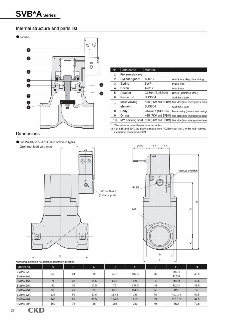
27
SVB*A Series
SVB1A
Internal structure and parts list
Dimensions
SVB*A-8A
SVB*A-10A
SVB*A-15A
SVB*A-20A
SVB*A-25A
SVB*A-32A
SVB*A-40A
SVB*A-50A
A
50
71
80
90
125
140
160
B
24
28
35
43
55
61
76
C
12
14.5
17.5
21
27.5
30.5
38
D
45.5
65.5
75
85.5
113.5
134.5
168
E
102.5
125
137.5
151.5
186
210
251
F
32
43
43
53
63
77
95
Rc1/4
Rc3/8
Rc1/2
Rc3/4
Rc1
Rc1 1/4
Rc1 1/2
Rc2
N
48.5
49.5
49.5
53
57.5
64.5
72.5
Model no.
No.
1
2
3
4
5
6
7
8
9
10
Parts name
Pilot solenoid valve
Cylinder guard
Spring
Piston
Adaptor
Piston rod
Main valving
element
Body
O ring
MY packing seal
Material
-
ADC12
SWP
A2017
C3604 (SUS304)
SUS304
NBR (FKM and EPDM)
SUS304
CAC407 (SCS13)
NBR (FKM and EPDM)
NBR (FKM and EPDM)
-
Aluminum alloy die-casting
Piano wire
Aluminum
Brass (stainless steel)
Stainless steel
Nitrile rubber (fluoro, ethylene propylene diene)
Stainless steel
Bronze casting (stainless steel casting)
Nitrile rubber (fluoro, ethylene propylene diene)
Nitrile rubber (fluoro, ethylene propylene diene)
G
*1: The value in parentheses is for an option.*2: For 65F and 80F, the body is made from FC250 (cast iron), while main valving element is made from FKM.
*Drawing indicates no optional assembly direction.
SVB*A-8A to 50A-*2C (Rc screw-in type)
Grommet lead wire type
R
R
P
B
F
C
(300) 19.5 15.5
E
DRc1/8
A
N22
M5 depth 4.5
(Exhaust port)
Manual override
2-G
1
2
3
4
5
6
7
8
9
10
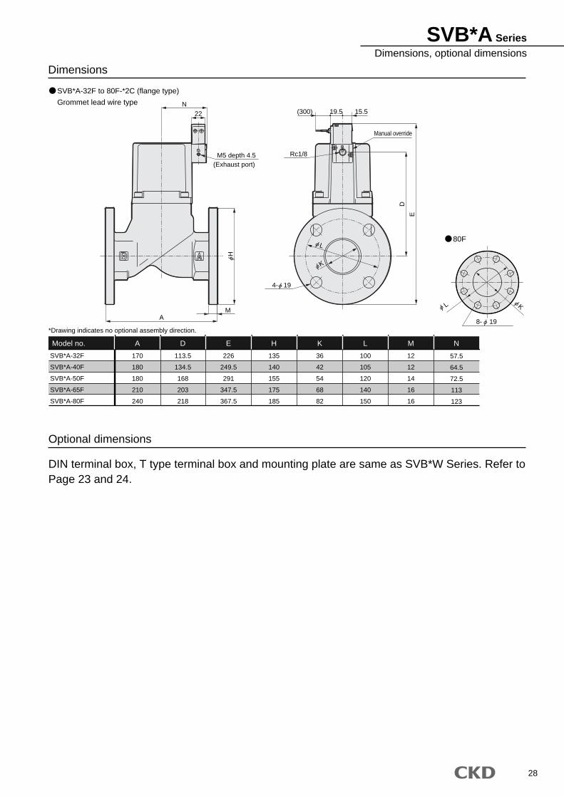
28
Dimensions
SVB*A-32F
SVB*A-40F
SVB*A-50F
SVB*A-65F
SVB*A-80F
A
170
180
180
210
240
D
113.5
134.5
168
203
218
E
226
249.5
291
347.5
367.5
H
135
140
155
175
185
K
36
42
54
68
82
L
100
105
120
140
150
12
12
14
16
16
N
57.5
64.5
72.5
113
123
Model no. M
*Drawing indicates no optional assembly direction.
DIN terminal box, T type terminal box and mounting plate are same as SVB*W Series. Refer to Page 23 and 24.
Optional dimensions
SVB*A-32F to 80F-*2C (flange type)
Grommet lead wire type
R
P
22N
M5 depth 4.5(Exhaust port)
MA
E
15.519.5(300)
Rc1/8
D
80F
Manual override
H
K
L
4- 19
8- 19
KL
SVB*A SeriesDimensions, optional dimensions
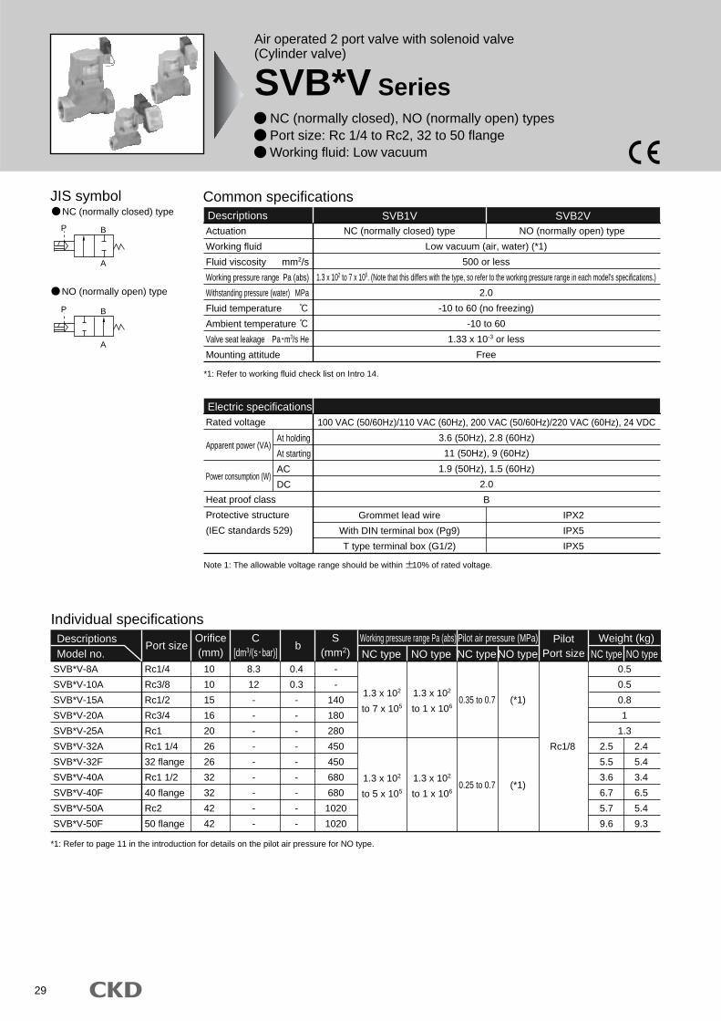
29
Air operated 2 port valve with solenoid valve(Cylinder valve)
SVB*V Series NC (normally closed), NO (normally open) types Port size: Rc 1/4 to Rc2, 32 to 50 flange Working fluid: Low vacuum
JIS symbol
B
A
P
B
A
P
NC (normally closed) type
NO (normally open) type
Common specificationsDescriptions SVB1V SVB2V
Low vacuum (air, water) (*1)
500 or less
1.3 x 10² to 7 x 10⁵. (Note that this differs with the type, so refer to the working pressure range in each model's specifications.)
2.0
-10 to 60 (no freezing)
-10 to 60
1.33 x 10⁻³ or less
Free
NC (normally closed) type NO (normally open) type
*1: Refer to working fluid check list on Intro 14.
Grommet lead wire
With DIN terminal box (Pg9)
T type terminal box (G1/2)
IPX2
IPX5
IPX5
Electric specificationsRated voltage
Apparent power (VA)
Power consumption (W)
Heat proof class
Protective structure
(IEC standards 529)
100 VAC (50/60Hz)/110 VAC (60Hz), 200 VAC (50/60Hz)/220 VAC (60Hz), 24 VDC
3.6 (50Hz), 2.8 (60Hz)
11 (50Hz), 9 (60Hz)
1.9 (50Hz), 1.5 (60Hz)
2.0
B
*1: Refer to page 11 in the introduction for details on the pilot air pressure for NO type.
Individual specificationsDescriptionsModel no.
Port size bWeight (kg)Pilot
Port size NC type NO typeNC type NO type NC typeNO typeSVB*V-8A
SVB*V-10A
SVB*V-15A
SVB*V-20A
SVB*V-25A
SVB*V-32A
SVB*V-32F
SVB*V-40A
SVB*V-40F
SVB*V-50A
SVB*V-50F
Rc1/4
Rc3/8
Rc1/2
Rc3/4
Rc1
Rc1 1/4
32 flange
Rc1 1/2
40 flange
Rc2
50 flange
10
10
15
16
20
26
26
32
32
42
42
8.3
12
-
-
-
-
-
-
-
-
-
0.4
0.3
-
-
-
-
-
-
-
-
-
-
-
140
180
280
450
450
680
680
1020
1020
Rc1/8
0.35 to 0.7 (*1)
0.5
0.5
0.8
1
1.3
2.5
5.5
3.6
6.7
5.7
9.6
2.4
5.4
3.4
6.5
5.4
9.3
Orifice(mm)
Working pressure range Pa (abs) Pilot air pressure (MPa)S(mm2)
1.3 x 10²
to 1 x 10⁶
1.3 x 10²
to 7 x 10⁵
0.25 to 0.7 (*1)1.3 x 10²
to 1 x 10⁶
1.3 x 10²
to 5 x 10⁵
At holding
At starting
AC
DC
Actuation
Working fluid
Fluid viscosity mm2/s
Working pressure range Pa (abs)
Withstanding pressure (water) MPa
Fluid temperature
Ambient temperature
Valve seat leakage Pa m3/s He
Mounting attitude
Note 1: The allowable voltage range should be within 10% of rated voltage.
C[dm3/(s bar)]
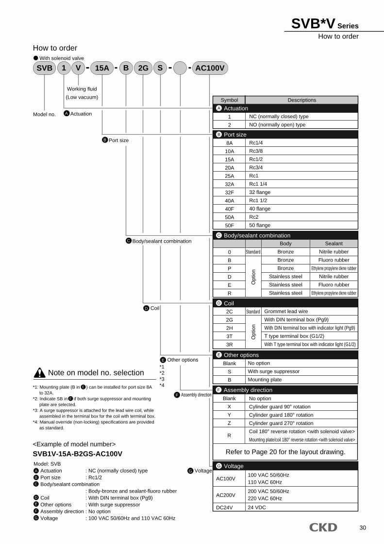
SVB*V SeriesHow to order
30
A
15A 2GSVB AC100V1 V B S
Model no.
Working fluid
(Low vacuum)
Actuation
B Port size
C Body/sealant combination
D Coil
E Other options
F Assembly direction
G Voltage
How to order
Model: SVBActuation : NC (normally closed) typePort size : Rc1/2Body/sealant combination
: Body-bronze and sealant-fluoro rubberCoil : With DIN terminal box (Pg9)Other options : With surge suppressorAssembly direction : No optionVoltage : 100 VAC 50/60Hz and 110 VAC 60Hz
<Example of model number>
SVB1V-15A-B2GS-AC100V
A
B
C
D
E
F
G
With solenoid valve
Note on model no. selection
*1: Mounting plate (B in ) can be installed for port size 8A to 32A.
*2: Indicate SB in if both surge suppressor and mounting plate are selected.
*3: A surge suppressor is attached for the lead wire coil, while assembled in the terminal box for the coil with terminal box.
*4: Manual override (non-locking) specifications are provided as standard.
E
E
ActuationA
2C
2G
2H
3T
3R
Grommet lead wire
With DIN terminal box (Pg9)
With DIN terminal box with indicator light (Pg9)
T type terminal box (G1/2)
With T type terminal box with indicator light (G1/2)
D
0
B
P
D
E
R
Standard
Body
Bronze
Bronze
Bronze
Stainless steel
Stainless steel
Stainless steel
Sealant
Nitrile rubber
Fluoro rubber
Ethylene propylene diene rubber
Nitrile rubber
Fluoro rubber
Ethylene propylene diene rubber
Body/sealant combinationC
Symbol Descriptions
1
2
NC (normally closed) type
NO (normally open) type
Port size
Coil
Voltage
B
8A
10A
15A
20A
25A
32A
32F
40A
40F
50A
50F
Rc1/4
Rc3/8
Rc1/2
Rc3/4
Rc1
Rc1 1/4
32 flange
Rc1 1/2
40 flange
Rc2
50 flange
Opt
ion
Standard
Opt
ion
Blank
S
B
No option
With surge suppressor
Mounting plate
Other optionsE
AC100V
AC200V
DC24V
100 VAC 50/60Hz110 VAC 60Hz
200 VAC 50/60Hz220 VAC 60Hz
24 VDC
VoltageG
Assembly directionF
Blank
X
Y
Z
R
No option
Cylinder guard 90° rotation
Cylinder guard 180° rotation
Cylinder guard 270° rotation
Coil 180° reverse rotation <with solenoid valve>
Mounting plate/coil 180° reverse rotation <with solenoid valve>
Refer to Page 20 for the layout drawing.
*1*2*3*4
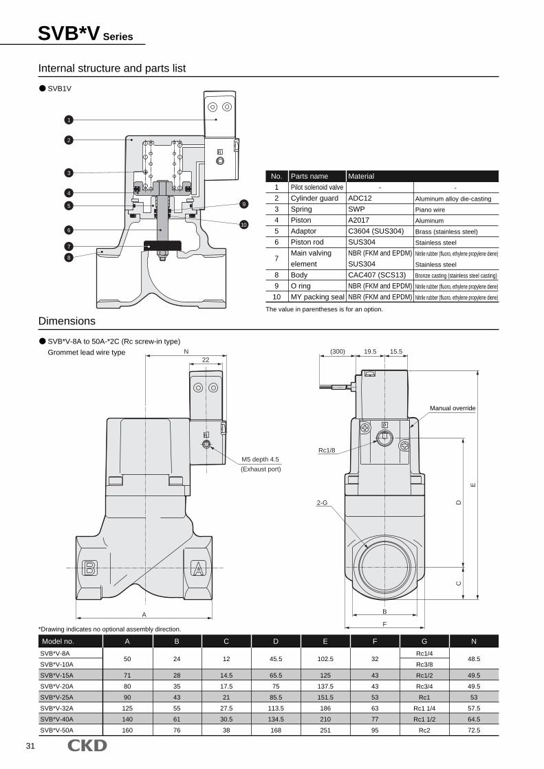
31
SVB*V Series
Internal structure and parts list
SVB1V
SVB*V-8A to 50A-*2C (Rc screw-in type)
Grommet lead wire type
Dimensions
SVB*V-8A
SVB*V-10A
SVB*V-15A
SVB*V-20A
SVB*V-25A
SVB*V-32A
SVB*V-40A
SVB*V-50A
A
50
71
80
90
125
140
160
B
24
28
35
43
55
61
76
C
12
14.5
17.5
21
27.5
30.5
38
D
45.5
65.5
75
85.5
113.5
134.5
168
E
102.5
125
137.5
151.5
186
210
251
F
32
43
43
53
63
77
95
Rc1/4
Rc3/8
Rc1/2
Rc3/4
Rc1
Rc1 1/4
Rc1 1/2
Rc2
N
48.5
49.5
49.5
53
57.5
64.5
72.5
Model no.
No.
1
2
3
4
5
6
7
8
9
10
Parts name
Pilot solenoid valve
Cylinder guard
Spring
Piston
Adaptor
Piston rod
Main valving
element
Body
O ring
MY packing seal
Material
-
ADC12
SWP
A2017
C3604 (SUS304)
SUS304
NBR (FKM and EPDM)
SUS304
CAC407 (SCS13)
NBR (FKM and EPDM)
NBR (FKM and EPDM)
-
Aluminum alloy die-casting
Piano wire
Aluminum
Brass (stainless steel)
Stainless steel
Nitrile rubber (fluoro, ethylene propylene diene)
Stainless steel
Bronze casting (stainless steel casting)
Nitrile rubber (fluoro, ethylene propylene diene)
Nitrile rubber (fluoro, ethylene propylene diene)
G
The value in parentheses is for an option.
*Drawing indicates no optional assembly direction.
R
R
P
B
F
C
(300) 19.5 15.5
E
DRc1/8
A
N22
M5 depth 4.5
(Exhaust port)
Manual override
2-G
1
2
3
4
5
6
7
8
9
10
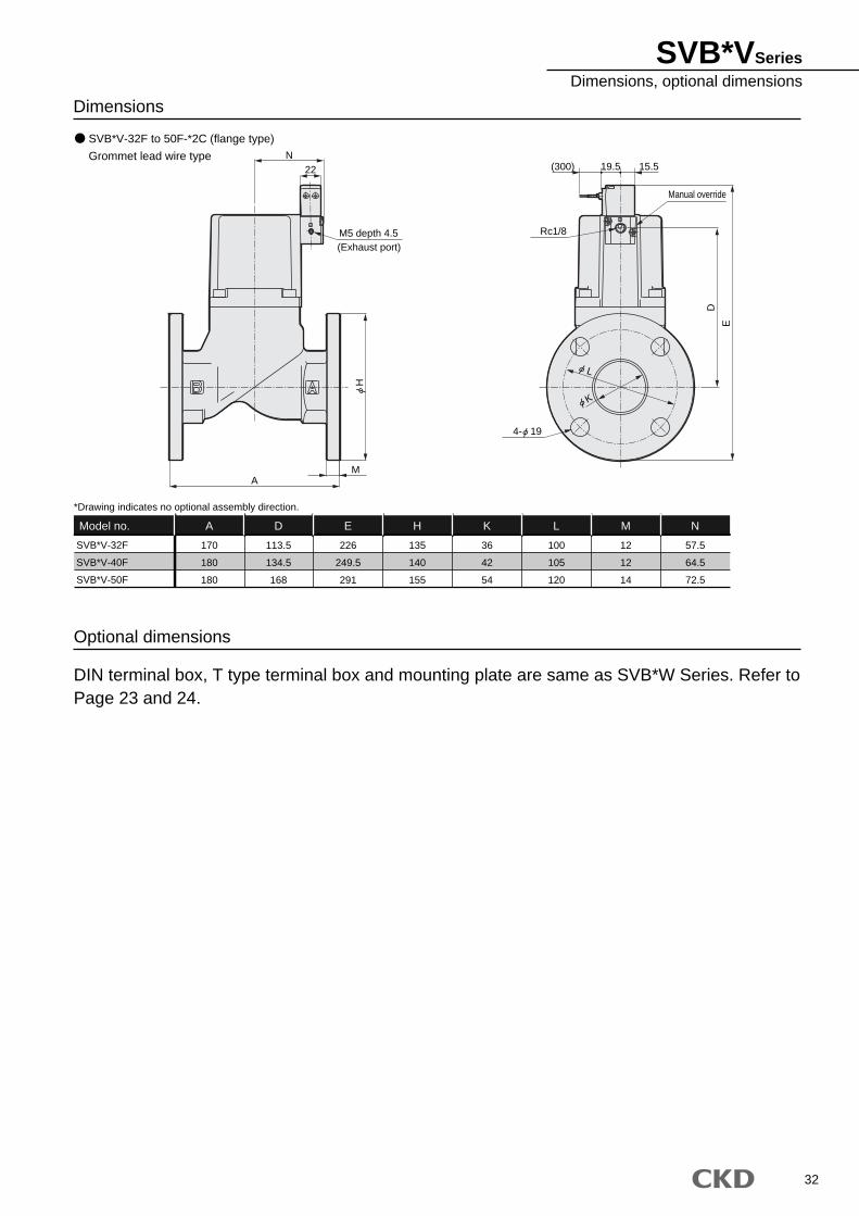
32
SVB*VSeriesDimensions, optional dimensions
Dimensions
SVB*V-32F
SVB*V-40F
SVB*V-50F
A
170
180
180
D
113.5
134.5
168
E
226
249.5
291
H
135
140
155
K
36
42
54
L
100
105
120
12
12
14
N
57.5
64.5
72.5
Model no. M
*Drawing indicates no optional assembly direction.
DIN terminal box, T type terminal box and mounting plate are same as SVB*W Series. Refer to Page 23 and 24.
Optional dimensions
SVB*V-32F to 50F-*2C (flange type)
Grommet lead wire type
R
P
22N
M5 depth 4.5(Exhaust port)
MA
E
15.519.5(300)
Rc1/8
D
Manual override
H
K
L
4- 19
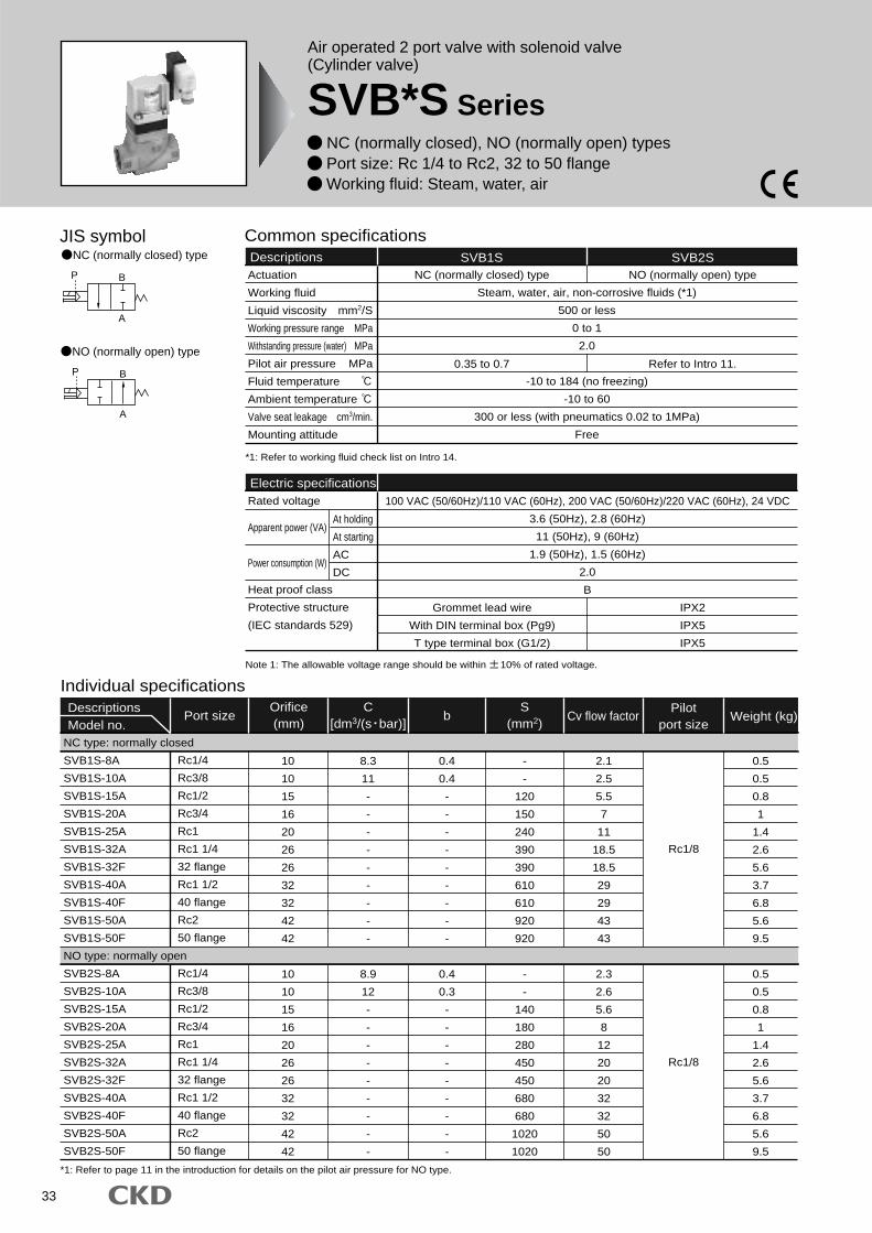
33
Air operated 2 port valve with solenoid valve(Cylinder valve)
SVB*S Series NC (normally closed), NO (normally open) types Port size: Rc 1/4 to Rc2, 32 to 50 flange Working fluid: Steam, water, air
JIS symbol
B
A
P
BP
A
NC (normally closed) type
NO (normally open) type
Individual specificationsDescriptionsModel no.
Port size b Weight (kg)Cv flow factorPilot
port sizeOrifice(mm)
S(mm2)
C[dm3/(s bar)]
Common specificationsDescriptions SVB1S
Steam, water, air, non-corrosive fluids (*1)
500 or less
0 to 1
2.0
-10 to 184 (no freezing)
-10 to 60
300 or less (with pneumatics 0.02 to 1MPa)
Free
NC (normally closed) type
SVB2SNO (normally open) type
0.35 to 0.7 Refer to Intro 11.
*1: Refer to working fluid check list on Intro 14.
*1: Refer to page 11 in the introduction for details on the pilot air pressure for NO type.
Rc1/4
Rc3/8
Rc1/2
Rc3/4
Rc1
Rc1 1/4
32 flange
Rc1 1/2
40 flange
Rc2
50 flange
Rc1/4
Rc3/8
Rc1/2
Rc3/4
Rc1
Rc1 1/4
32 flange
Rc1 1/2
40 flange
Rc2
50 flange
10
10
15
16
20
26
26
32
32
42
42
10
10
15
16
20
26
26
32
32
42
42
8.3
11
-
-
-
-
-
-
-
-
-
8.9
12
-
-
-
-
-
-
-
-
-
0.4
0.4
-
-
-
-
-
-
-
-
-
0.4
0.3
-
-
-
-
-
-
-
-
-
-
-
120
150
240
390
390
610
610
920
920
-
-
140
180
280
450
450
680
680
1020
1020
Rc1/8
Rc1/8
NC type: normally closed
SVB1S-8A
SVB1S-10A
SVB1S-15A
SVB1S-20A
SVB1S-25A
SVB1S-32A
SVB1S-32F
SVB1S-40A
SVB1S-40F
SVB1S-50A
SVB1S-50F
NO type: normally open
SVB2S-8A
SVB2S-10A
SVB2S-15A
SVB2S-20A
SVB2S-25A
SVB2S-32A
SVB2S-32F
SVB2S-40A
SVB2S-40F
SVB2S-50A
SVB2S-50F
2.1
2.5
5.5
7
11
18.5
18.5
29
29
43
43
2.3
2.6
5.6
8
12
20
20
32
32
50
50
0.5
0.5
0.8
1
1.4
2.6
5.6
3.7
6.8
5.6
9.5
0.5
0.5
0.8
1
1.4
2.6
5.6
3.7
6.8
5.6
9.5
IPX2
IPX5
IPX5
Electric specificationsRated voltage
Apparent power (VA)
Power consumption (W)
Heat proof class
Protective structure
(IEC standards 529)
100 VAC (50/60Hz)/110 VAC (60Hz), 200 VAC (50/60Hz)/220 VAC (60Hz), 24 VDC
3.6 (50Hz), 2.8 (60Hz)
11 (50Hz), 9 (60Hz)
1.9 (50Hz), 1.5 (60Hz)
2.0
B
At holding
At starting
AC
DC
Actuation
Working fluid
Liquid viscosity mm2/S
Working pressure range MPa
Withstanding pressure (water) MPa
Pilot air pressure MPa
Fluid temperature
Ambient temperature
Valve seat leakage cm3/min.
Mounting attitude
Note 1: The allowable voltage range should be within 10% of rated voltage.
Grommet lead wire
With DIN terminal box (Pg9)
T type terminal box (G1/2)

A
15A 2GSVB AC100V1 S E L
Model no.
Working fluid
(Steam, water, air)
Actuation
B Port size
C Body/sealant combination
D Coil
E Other options
G Voltage
F Assembly direction
How to order
Model: SVBActuation : NC (normally closed) typePort size : Rc1/2Body/sealant combination
: Body-stainless steel and sealant-tetrafluoroethylene resinWith coil : DIN terminal box (Pg9)Other options : With indicatorAssembly direction : No optionVoltage : 100 VAC 50/60Hz and 110 VAC 60Hz
<Example of model number>
SVB1S-15A-E2GL-AC100V
A
B
C
D
F
G
E
With solenoid valve
Note on model no. selection
E
E
E
*1: Select C or E for steam.*2: Mounting plate (B in ) can be installed for port size 8A to
32A.*3: Indicator (L in ) is installed for only actuation 1: NC type.*4: Indicate as followings if options are selected .
Surge suppressor + mounting plate SBSurge suppressor + indicator SLMounting plate + indicator BLSurge suppressor + mounting plate + indicator SBL
*5: A surge suppressor is attached for the lead wire coil, while assembled in the terminal box for the coil with terminal box.
*6: Manual override (non-locking) specifications are provided as standard.
ActuationA
2C
2G
2H
3T
3R
Grommet lead wire
With DIN terminal box (Pg9)
With DIN terminal box with indicator light (Pg9)
T type terminal box (G1/2)
With T type terminal box with indicator light (G1/2)
D
Symbol Descriptions
1
2
NC (normally closed) type
NO (normally open) type
Port size
Coil
Voltage
B
8A
10A
15A
20A
25A
32A
32F
40A
40F
50A
50F
Rc1/4
Rc3/8
Rc1/2
Rc3/4
Rc1
Rc1 1/4
32 flange
Rc1 1/2
40 flange
Rc2
50 flange
Standard
Opt
ion
Blank
S
B
L
No option
With surge suppressor
Mounting plate
With indicator
Other optionsE
AC100V
AC200V
DC24V
100 VAC 50/60Hz110 VAC 60Hz
200 VAC 50/60Hz220 VAC 60Hz
24 VDC
VoltageG
C
E
F
Body Sealant O ring Remarks
Body/sealant combinationC
Bronze
Stainless steel
Stainless steel
Tetrafluoroethylene resin
Tetrafluoroethylene resin
Tetrafluoroethylene resin
Fluoro rubber
Fluoro rubber
Tetrafluoroethylene resin
Steam/air/
water
Solvent
Assembly directionF
Blank
X
Y
Z
R
No option
Cylinder guard 90° rotation
Cylinder guard 180° rotation
Cylinder guard 270° rotation
Coil 180° reverse rotation <with solenoid valve>
Mounting plate/coil 180° reverse rotation <with solenoid valve>
Refer to Page 20 for the layout drawing.
*2*3*4*5*6
*1
34
SVB*S SeriesHow to order
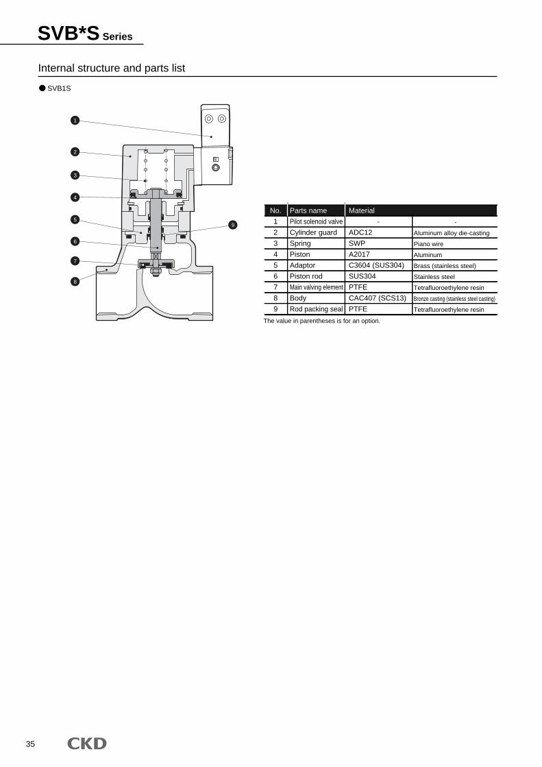
35
SVB*S Series
Internal structure and parts list
No.
1
2
3
4
5
6
7
8
9
Parts name
Pilot solenoid valve
Cylinder guard
Spring
Piston
Adaptor
Piston rod
Main valving element
Body
Rod packing seal
Material
-
ADC12
SWP
A2017
C3604 (SUS304)
SUS304
PTFE
CAC407 (SCS13)
PTFE
-
Aluminum alloy die-casting
Piano wire
Aluminum
Brass (stainless steel)
Stainless steel
Tetrafluoroethylene resin
Bronze casting (stainless steel casting)
Tetrafluoroethylene resin
SVB1S
The value in parentheses is for an option.
R
1
2
3
4
5
6
7
8
9
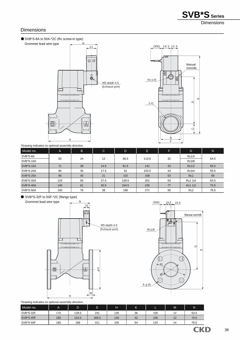
36
SVB*S SeriesDimensions
SVB*S-32F to 50F-*2C (flange type)
Grommet lead wire type
SVB*S-32F
SVB*S-40F
SVB*S-50F
A
170
180
180
D
128.5
154.5
188
E
241
269.5
311
H
135
140
155
K
36
42
54
L
100
105
120
12
12
14
N
63.5
70.5
78.5
Model no. M
SVB*S-8A
SVB*S-10A
SVB*S-15A
SVB*S-20A
SVB*S-25A
SVB*S-32A
SVB*S-40A
SVB*S-50A
A
50
71
80
90
125
140
160
B
24
28
35
43
55
61
76
C
12
14.5
17.5
21
27.5
30.5
38
D
56.5
81.5
91
102
128.5
154.5
188
E
113.5
141
153.5
168
201
230
271
F
32
43
43
53
63
77
95
Rc1/4
Rc3/8
Rc1/2
Rc3/4
Rc1
Rc1 1/4
Rc1 1/2
Rc2
N
54.5
55.5
55.5
59
63.5
70.5
78.5
Model no. G
SVB*S-8A to 50A-*2C (Rc screw-in type)
Grommet lead wire type
Dimensions
*Drawing indicates no optional assembly direction.
*Drawing indicates no optional assembly direction.
RR
15.519.5E
D
N22
M5 depth 4.5(Exhaust port) Rc1/8
AM
(300)
Manual override
M5 depth 4.5(Exhaust port)
Rc1/8
A
2-G
BF
(300) 19.5 15.5
Manualoverride
N22
D
E
C
L
K
4- 19
H
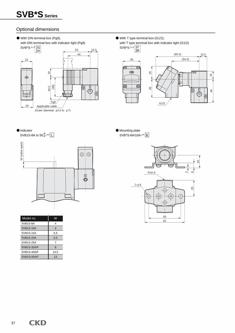
37
Optional dimensions
Mounting plate
SVB*S-8A/10A-** B
2G2H
3T3R
Indicator
SVB1S-8A to 50 -** LAF
SVB1S-8A
SVB1S-10A
SVB1S-15A
SVB1S-20A
SVB1S-25A
SVB1S-32A/F
SVB1S-40A/F
SVB1S-50A/F
W
4
4
6.5
6.5
7
8
10.5
13
Model no.
With DIN terminal box (Pg9),
with DIN terminal box with indicator light (Pg9)
SVB*S-*-*
With T type terminal box (G1/2),
with T type terminal box with indicator light (G1/2)
SVB*S-*-*
RR
P
P
R
Port A 82
20
62
50
25
15.5
3626
4616
G1/2
(54.5)
(85.5)
3522
24
15.518
44
53(3
8)
44.5
Applicable cable
Pg9
W (
valv
e op
en)
2- 6
(Outer diameter 4.5 to 7)
SVB*S Series
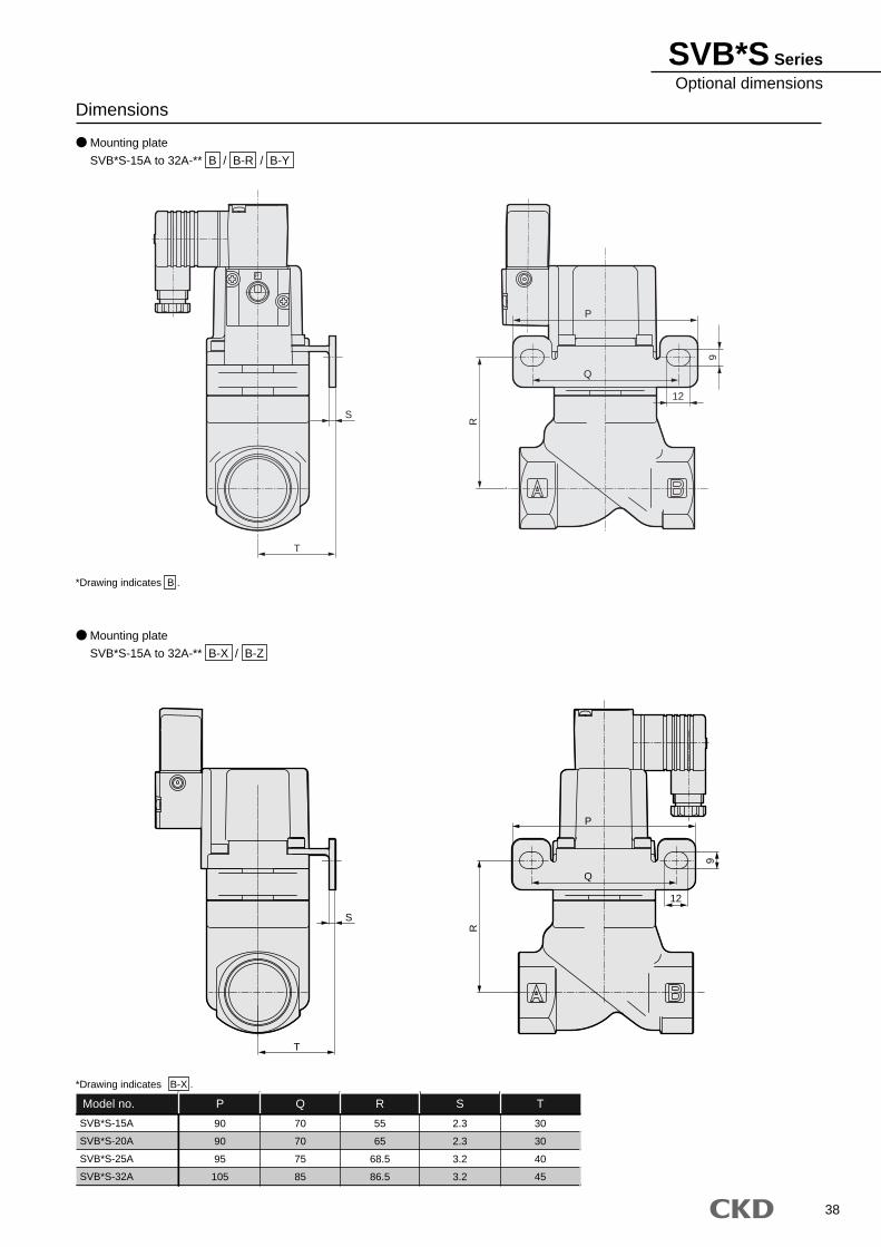
38
Dimensions
Mounting plate
SVB*S-15A to 32A-** B / B-R / B-Y
Mounting plate
SVB*S-15A to 32A-** B-X / B-Z
*Drawing indicates B .
SVB*S-15A
SVB*S-20A
SVB*S-25A
SVB*S-32A
P
90
90
95
105
Q
70
70
75
85
R
55
65
68.5
86.5
S
2.3
2.3
3.2
3.2
T
30
30
40
45
Model no.
*Drawing indicates B-X .
P
T
S
Q
12
P
R
9
S
P
Q
12
R
9
T
SVB*S SeriesOptional dimensions
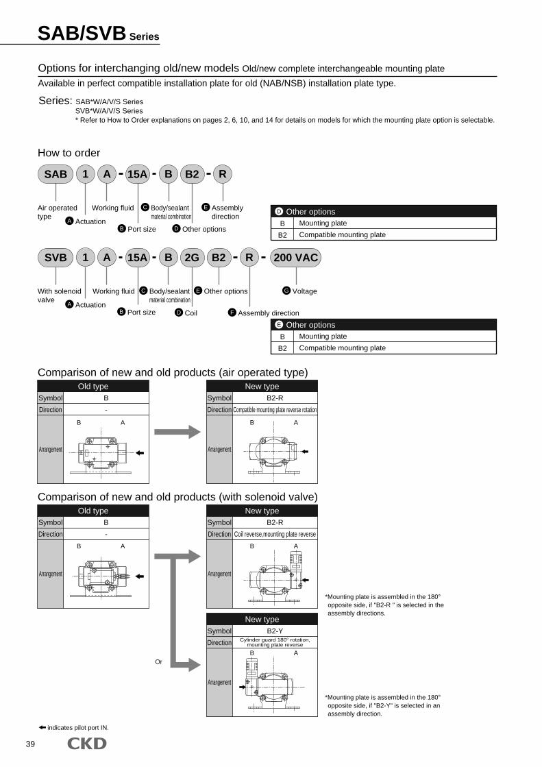
39
Options for interchanging old/new models Old/new complete interchangeable mounting plate
Available in perfect compatible installation plate for old (NAB/NSB) installation plate type.
Series: SAB*W/A/V/S SeriesSVB*W/A/V/S Series* Refer to How to Order explanations on pages 2, 6, 10, and 14 for details on models for which the mounting plate option is selectable.
SAB B R1 A B215A
A Actuation
Working fluidAir operatedtype
How to order
C Body/sealantmaterial combination
E Assemblydirection
D Other optionsB Port sizeB
B2
Mounting plate
Compatible mounting plate
Other optionsD
SVB 200 VACB1 A 2G15A
A Actuation
Working fluidWith solenoidvalve
C Body/sealantmaterial combination
G VoltageE Other options
D Coil F Assembly direction
RB2
B Port size
B
B2
Mounting plate
Compatible mounting plate
Other optionsE
Comparison of new and old products (air operated type)Old type
Symbol
Direction
Arrangement
B
-
New typeSymbol
Direction
Arrangement
B2-R
Compatible mounting plate reverse rotation
Comparison of new and old products (with solenoid valve)Old type
Symbol
Direction
Arrangement
B
-
New typeSymbol
Direction
Arrangement
B2-R
Coil reverse,mounting plate reverse
New typeSymbol
Direction
Arrangement
B2-YCylinder guard 180° rotation,
mounting plate reverse
*Mounting plate is assembled in the 180° opposite side, if "B2-R " is selected in the assembly directions.
*Mounting plate is assembled in the 180° opposite side, if "B2-Y" is selected in an assembly direction.
Or
B A
B A
B A
B A
B A
indicates pilot port IN.
SAB/SVB Series
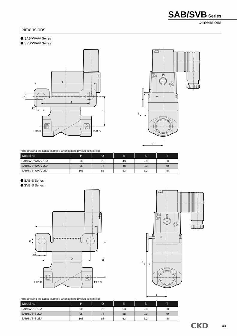
40
SAB/SVB SeriesDimensions
Dimensions
SAB*W/A/V Series
SVB*W/A/V Series
SAB/SVB*W/A/V-15A
SAB/SVB*W/A/V-20A
SAB/SVB*W/A/V-25A
P
90
95
105
Q
70
75
85
R
43
48
53
S
2.3
2.3
3.2
T
30
40
45
Model no.
SAB/SVB*S-15A
SAB/SVB*S-20A
SAB/SVB*S-25A
P
90
95
105
Q
70
75
85
R
53
58
63
S
2.3
2.3
3.2
T
30
40
45
Model no.
SAB*S Series
SVB*S Series
*The drawing indicates example when solenoid valve is installed.
*The drawing indicates example when solenoid valve is installed.
P
P
12
Port B Port A
S
T
P
Q
9
R
P
S
T
Q
12
R
9
Port APort B
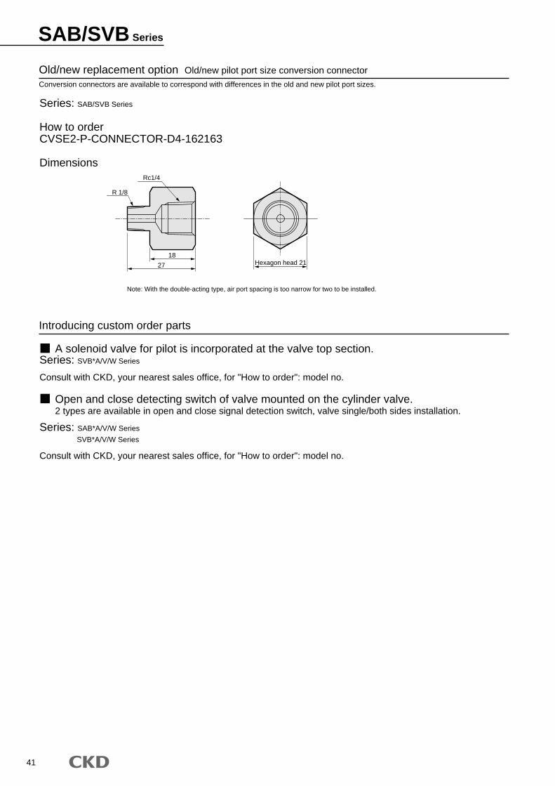
41
SAB/SVB Series
Old/new replacement option Old/new pilot port size conversion connectorConversion connectors are available to correspond with differences in the old and new pilot port sizes.
Series: SAB/SVB Series
How to orderCVSE2-P-CONNECTOR-D4-162163
Dimensions
Introducing custom order parts
Note: With the double-acting type, air port spacing is too narrow for two to be installed.
A solenoid valve for pilot is incorporated at the valve top section.Series: SVB*A/V/W Series
Consult with CKD, your nearest sales office, for "How to order": model no.
Open and close detecting switch of valve mounted on the cylinder valve. 2 types are available in open and close signal detection switch, valve single/both sides installation.
Series: SAB*A/V/W Series
SVB*A/V/W Series
Consult with CKD, your nearest sales office, for "How to order": model no.
Rc1/4
R 1/8
18Hexagon head 2127

42
M E M OM E M O

2007.5.ACC●Specifications are subject to change without notice.
The goods and their replicas, or the technology and software in this catalog are subject to complementary export regulations by Foreign Exchange and Foreign Trade Law of Japan.If the goods and their replicas, or the technology and software in this catalog are to be exported, laws require the exporter to make sure they will never be used for the development or the manufacture of weapons for mass destruction.
CKD CORPORATION TAIWAN BRANCH
M-CKD PRECISION SDN.BHD.CKD USA CORPORATION
CKD UK OFFICE
CKD CORPORATION EUROPE BRANCH
CKD BELGIUM OFFICE
CKD CO.,LTD.,o.s. CZECH OFFICE
CKD KOREA CORPORATION
CKD THAI CORPORATION LTD.
CKD SINGAPORE PTE. LTD.
●WUXI OFFICE ●NANJING OFFICE ●HANGZHOU OFFICE ●WUHAN OFFICE ●QINGDAO OFFICE
●SUZHOU OFFICE ●BEJING OFFICE ●TIANJING OFFICE ●CHANG CHUN OFFICE ●DALIAN OFFICE
●SHENYANG OFFICE ●XIAN OFFICE ●CHONGQING OFFICE ●CHENGDU OFFICE ●GUANGZHOU OFFICE ●SHENZHEN OFFICE
●CINCINNATI OFFICE ●SAN ANTONIO OFFICE ●SAN JOSE OFFICE
●JOHOR BAHRU OFFICE ●MELAKA OFFICE ●PENANG OFFICE
●LAEMCHABANG OFFICE ●NAVANAKORN OFFICE ●RAYONG OFFICE ●LAMPHUN OFFICE ●KORAT OFFICE ●AMATANAKORN OFFICE
CKD(SHANGHAI) CORPORATION
:Distributors
●HWASEONG OFFICE
CKD CANADA
□ OVERSEAS DPT. SALES DIV. 2-250 Ouji Komaki, Aichi 485-8551, Japan □ PHONE +81-(0)568-74-1338 FAX +81-(0)568-77-3461
Website http://www.ckd.co.jp/
U.S.A CKD USA CORPORATION ● HEADQUARTERS 4080 Winnetka Avenue, Rolling Meadows, IL 60008 USA PHONE +1-847-368-0539 FAX +1-847-788-0575
EUROPE CKD EUROPE BRANCH De Fruittuinen 28 Hoofddorp 2132NZ The Netherlands PHONE +31-(0)23-5541490 FAX +31-(0)23-5541491
Malaysia M-CKD PRECISION SDN.BHD. ● HEADQUARTERS Lot No.6,Jalan Modal 23/2, Seksyen 23, Kawasan, MIEL, Fasa 8, 40300 Shah Alam,Selangor Darul Ehsan, Malaysia PHONE +60-(0)3-5541-1468 FAX +60-(0)3-5541-1533
Thailand CKD THAI CORPORATION LTD. ● SALES HEADQUARTERS-BANGKOK OFFICE Suwan Tower, 14/1 Soi Saladaeng 1, North Sathorn Rd., Bangrak, Bangkok 10500 Thailand PHONE +66-(0)2-267-6300 FAX +66-(0)2-267-6305
Singapore CKD SINGAPORE PTE LTD. 705 Sims Drive #03-01/02, Shun Li Industrial Complex, 387384 Singapore PHONE +65-6744-2623 FAX +65-6744-2486
Taiwan CKD CORPORATION TAIWAN BRANCH Rm.1405, 14F, No.96, Sec.2, Chung Shan N.Rd., Taipei, Taiwan, R.O.C. PHONE +886-(0)2-2523-0374 FAX +886-(0)2-2523-5081
China CKD (SHANGHAI) CORPORATION ● SALES HEADQUARTERS / SHANGHAI OFFICE Room 1903, 333 Jiujiang Road, Shanghai, 200001, China PHONE +86-(0)21-63602277 FAX +86-(0)21-63511661
Korea CKD KOREA CORPORATION Room No.1105, 11th FL, The Korea Teachers Pention B/L. 27-2, Yoido-Dong, Youngdeungpo-Gu, Seoul, 150-742, Korea PHONE +82-(0)2-783-5201~5203 FAX +82-(0)2-783-5204