Embed Size (px)
Citation preview
Manual No. BLWR001Rev. 6 October 2012 oPerAtinG mAnUAl
moDelS:SVB-e8
SVB-e8-2SVB-e8ec
SVB-e8eXP
SVB-A8SVB-G8
SVB-G8P
Air Systems International SVB-A8 Air Powered Blower Air Systems International SVB-E14 Centrifugal Blower Air Systems International SVB-E8 VentilatorAir Systems International SVB-E8-2 Two Speed Blower Air Systems International SVB-E8EC Electric Blower Air Systems International SVB-E8EXP Electric Blower Air Systems International SVB-G8 Gasoline Blower Air Systems SVB-A8CUP Pneumatic BlowerAir Systems SVB-E8XCUP Saddle Vent Kit
actoolsupply.com
actoolsupply.com
actoolsupply.com
SAFety PrecAUtionSreAD AnD FolloW All inStrUctionS BeloW
All venti lati on procedures should comply with federal, state, and local regulati ons. Air quality should be tested prior to venti lati ng a confi ned space. A purge chart is provided in this manual help assist in esti mati ng the approximate ti me needed to venti late confi ned spaces. Air quality should be tested conti nuously during confi ned space occupancy to ensure a stable atmosphere and worker safety as atmospheric conditi ons can change rapidly. Additi onal pro-cedures and recommendati ons are available from federal, state, and local agencies. Do not operate these fan units in a verti cal positi on or with the fl ange or guards removed.
WArninGFan and blower models with the “EX” or “X” designati on are
the only models approved for use in hazardous locati ons.
If volati le or explosive vapors are suspected, use Air Systems’ explosion proof electric blower, Model SVB-E8EXP, explosion proof in-line fan, Model SVF-10EXP, explosion proof contractors fan, Model CVF-8EXP or Air Systems’ intrinsically safe pneumati c blower, Model SVB-A8.
Note: For confi ned space venti lati on in non-hazardous locati ons, use Air Systems’ confi ned space venti lati on kit, Model SV-CUP. For hazardous locati ons use venti lati on kit, Model SV-CUPCND along with one of the above explosion proof blowers or fans.
2actoolsupply.com
actoolsupply.com
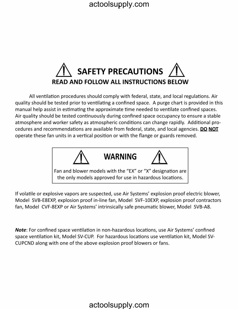
The Saddle Vent® Venti lati on SystemTypical Saddle Vent® Setup Procedure
Place fan or blower a minimumof 5 ft . from manhole opening
Blower or Fan
90° Elbow
ManholeOpeningManhole Lid
Universal MountSaddle Vent®Select a blower or fan based on environmental
conditi ons and the size of the confi ned space.For informati on or guidance in selecti ng the
proper set-up, please contact Customer Service.
STEP 1) Install 6 ft . duct on blower or fanSTEP 2) Install 90° elbow on top of Saddle Vent®STEP 3) Install duct on bott om of Saddle Vent®STEP 4) Install universal mount on Saddle Vent® and set in place with manhole lid for supportSTEP 5) Install duct from blower to 90° elbowSTEP 6) Turn on blower or fan
Warning: For explosive environments,follow ANSI/API 2015 and 2016 procedures
WArninG: HAZArDoUS locAtion oPerAtionSUse an explosion-proof or intrinsically safe blower or fan,
conducti ve ducti ng, and the conducti ve Saddle Vent® system.Att ach all grounding wires and assure a complete circuit to the
blower or fan in order to remove stati c charges.
3actoolsupply.com
actoolsupply.com
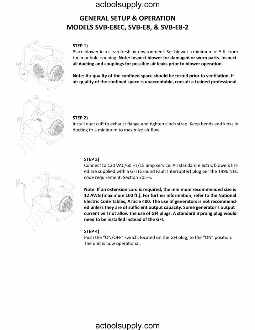
GenerAl SetUP & oPerAtionmoDelS SVB-e8ec, SVB-e8, & SVB-e8-2
SteP 1)Place blower in a clean fresh air environment. Set blower a minimum of 5 ft. from the manhole opening. Note: Inspect blower for damaged or worn parts. Inspect all ducting and couplings for possible air leaks prior to blower operation.
Note: Air quality of the confined space should be tested prior to ventilation. If air quality of the confined space is unacceptable, consult a trained professional.
SteP 2)Install duct cuff to exhaust flange and tighten cinch strap. Keep bends and kinks in ducting to a minimum to maximize air flow.
SteP 3)Connect to 120 VAC/60 Hz/15 amp service. All standard electric blowers list-ed are supplied with a GFI (Ground Fault Interrupter) plug per the 1996 NEC code requirement: Section 305-6.
Note: If an extension cord is required, the minimum recommended size is 12 AWG (maximum 100 ft.). For further information; refer to the National Electric Code Tables, Article 400. The use of generators is not recommend-ed unless they are of sufficient output capacity. Some generator’s output current will not allow the use of GFI plugs. A standard 3 prong plug would need to be installed instead of the GFI.
STEP 4)Push the “ON/OFF” switch, located on the GFI plug, to the “ON” position. The unit is now operational.
4actoolsupply.com
actoolsupply.com
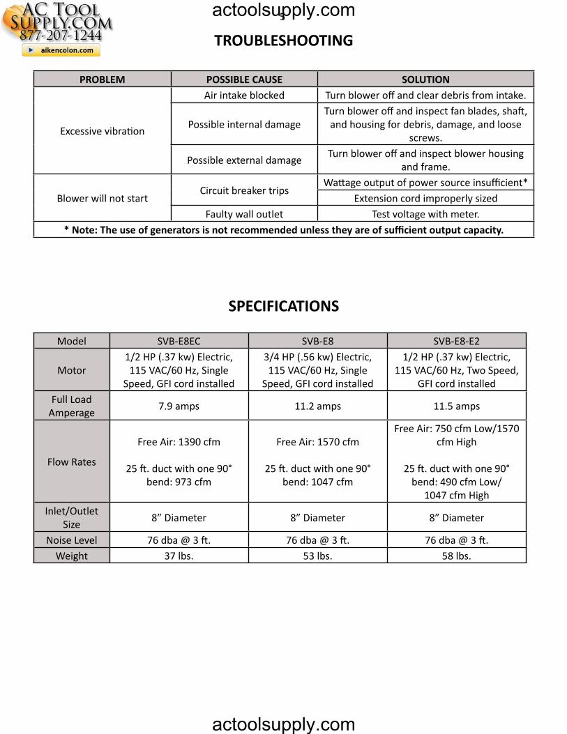
troUBleSHootinG
SPeciFicAtionS
ProBlem PoSSiBle cAUSe SolUtion
Excessive vibration
Air intake blocked Turn blower off and clear debris from intake.
Possible internal damageTurn blower off and inspect fan blades, shaft,
and housing for debris, damage, and loose screws.
Possible external damage Turn blower off and inspect blower housing and frame.
Blower will not startCircuit breaker trips
Wattage output of power source insufficient*Extension cord improperly sized
Faulty wall outlet Test voltage with meter.* Note: The use of generators is not recommended unless they are of sufficient output capacity.
Model SVB-E8EC SVB-E8 SVB-E8-E2
Motor1/2 HP (.37 kw) Electric, 115 VAC/60 Hz, Single
Speed, GFI cord installed
3/4 HP (.56 kw) Electric, 115 VAC/60 Hz, Single
Speed, GFI cord installed
1/2 HP (.37 kw) Electric, 115 VAC/60 Hz, Two Speed,
GFI cord installedFull Load
Amperage 7.9 amps 11.2 amps 11.5 amps
Flow Rates
Free Air: 1390 cfm
25 ft. duct with one 90° bend: 973 cfm
Free Air: 1570 cfm
25 ft. duct with one 90° bend: 1047 cfm
Free Air: 750 cfm Low/1570 cfm High
25 ft. duct with one 90° bend: 490 cfm Low/
1047 cfm HighInlet/Outlet
Size 8” Diameter 8” Diameter 8” Diameter
Noise Level 76 dba @ 3 ft. 76 dba @ 3 ft. 76 dba @ 3 ft.Weight 37 lbs. 53 lbs. 58 lbs.
5actoolsupply.com
actoolsupply.com
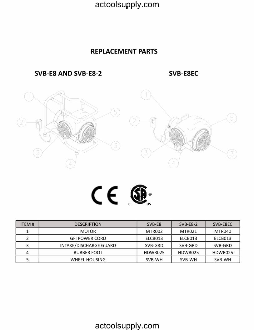
rePlAcement PArtS
SVB-e8 AnD SVB-e8-2 SVB-e8ec
c US
®
ITEM # DESCRIPTION SVB-E8 SVB-E8-2 SVB-E8EC1 MOTOR MTR002 MTR021 MTR0402 GFI POWER CORD ELCB013 ELCB013 ELCB0133 INTAKE/DISCHARGE GUARD SVB-GRD SVB-GRD SVB-GRD4 RUBBER FOOT HDWR025 HDWR025 HDWR0255 WHEEL HOUSING SVB-WH SVB-WH SVB-WH
6actoolsupply.com
actoolsupply.com
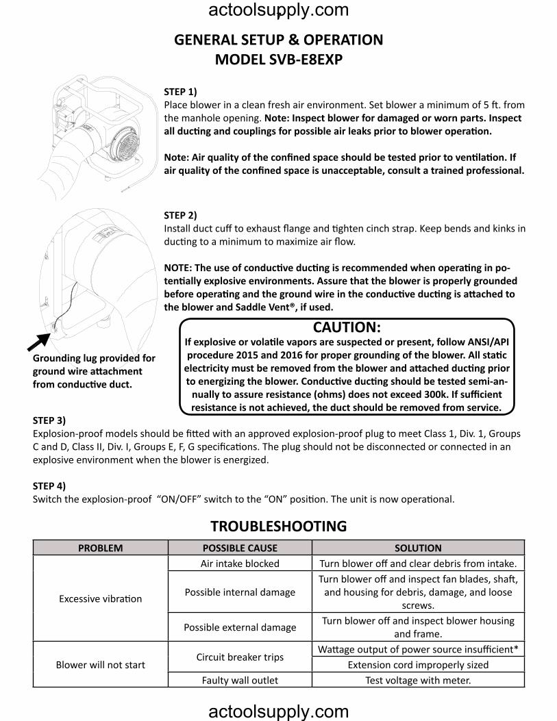
GenerAl SetUP & oPerAtionmoDel SVB-e8eXP
SteP 1)Place blower in a clean fresh air environment. Set blower a minimum of 5 ft. from the manhole opening. Note: Inspect blower for damaged or worn parts. Inspect all ducting and couplings for possible air leaks prior to blower operation.
Note: Air quality of the confined space should be tested prior to ventilation. If air quality of the confined space is unacceptable, consult a trained professional.
SteP 2)Install duct cuff to exhaust flange and tighten cinch strap. Keep bends and kinks in ducting to a minimum to maximize air flow.
NOTE: The use of conductive ducting is recommended when operating in po-tentially explosive environments. Assure that the blower is properly grounded before operating and the ground wire in the conductive ducting is attached to the blower and Saddle Vent®, if used.
Grounding lug provided for ground wire attachment from conductive duct.
SteP 3)Explosion-proof models should be fitted with an approved explosion-proof plug to meet Class 1, Div. 1, Groups C and D, Class II, Div. I, Groups E, F, G specifications. The plug should not be disconnected or connected in an explosive environment when the blower is energized.
STEP 4)Switch the explosion-proof “ON/OFF” switch to the “ON” position. The unit is now operational.
cAUtion:If explosive or volatile vapors are suspected or present, follow ANSI/API procedure 2015 and 2016 for proper grounding of the blower. All static
electricity must be removed from the blower and attached ducting prior to energizing the blower. Conductive ducting should be tested semi-an-
nually to assure resistance (ohms) does not exceed 300k. If sufficient resistance is not achieved, the duct should be removed from service.
ProBlem PoSSiBle cAUSe SolUtion
Excessive vibration
Air intake blocked Turn blower off and clear debris from intake.
Possible internal damageTurn blower off and inspect fan blades, shaft,
and housing for debris, damage, and loose screws.
Possible external damage Turn blower off and inspect blower housing and frame.
Blower will not startCircuit breaker trips
Wattage output of power source insufficient*Extension cord improperly sized
Faulty wall outlet Test voltage with meter.
troUBleSHootinG
7actoolsupply.com
actoolsupply.com
rePlAcement PArtS
SPeciFicAtionS
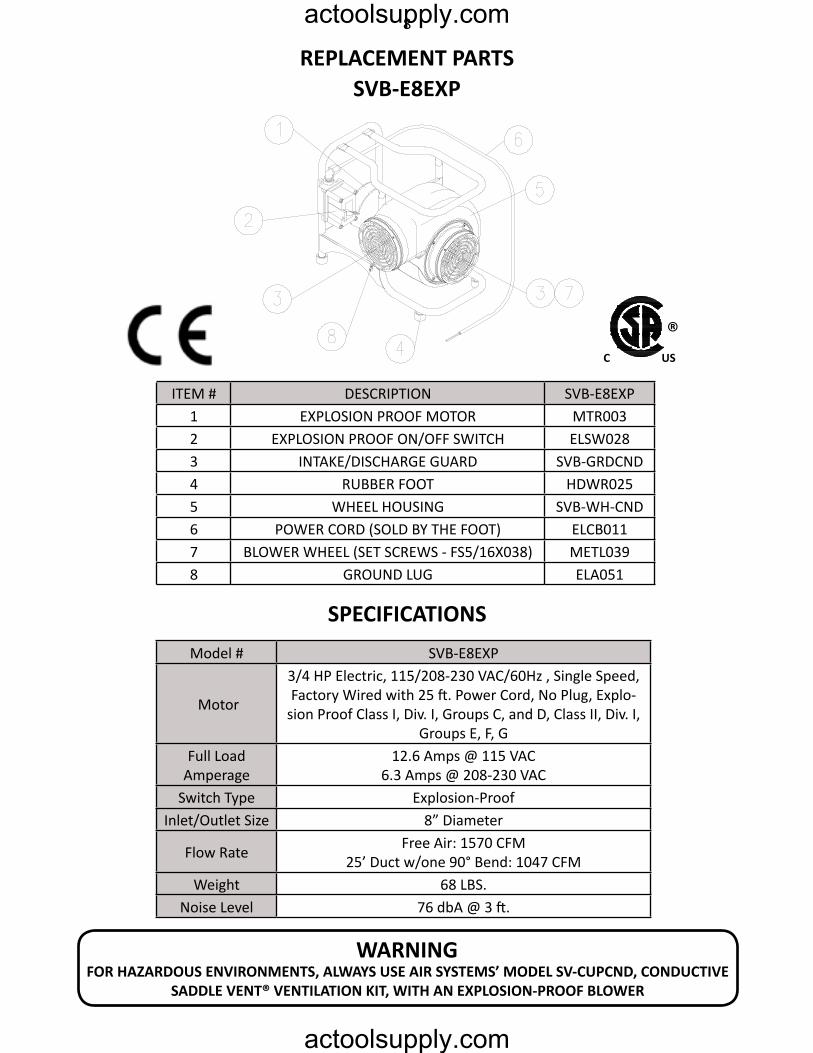
SVB-e8eXP
ITEM # DESCRIPTION SVB-E8EXP1 EXPLOSION PROOF MOTOR MTR0032 EXPLOSION PROOF ON/OFF SWITCH ELSW0283 INTAKE/DISCHARGE GUARD SVB-GRDCND4 RUBBER FOOT HDWR0255 WHEEL HOUSING SVB-WH-CND6 POWER CORD (SOLD BY THE FOOT) ELCB0117 BLOWER WHEEL (SET SCREWS - FS5/16X038) METL0398 GROUND LUG ELA051
c US
®
Model # SVB-E8EXP
Motor
3/4 HP Electric, 115/208-230 VAC/60Hz , Single Speed,Factory Wired with 25 ft. Power Cord, No Plug, Explo-
sion Proof Class I, Div. I, Groups C, and D, Class II, Div. I, Groups E, F, G
Full Load Amperage
12.6 Amps @ 115 VAC6.3 Amps @ 208-230 VAC
Switch Type Explosion-ProofInlet/Outlet Size 8” Diameter
Flow Rate Free Air: 1570 CFM25’ Duct w/one 90° Bend: 1047 CFM
Weight 68 LBS.Noise Level 76 dbA @ 3 ft.
WArninGFOR HAZARDOUS ENVIRONMENTS, ALWAYS USE AIR SYSTEMS’ MODEL SV-CUPCND, CONDUCTIVE
SADDle Vent® VentilAtion Kit, WitH An eXPloSion-ProoF BloWer
8actoolsupply.com
actoolsupply.com
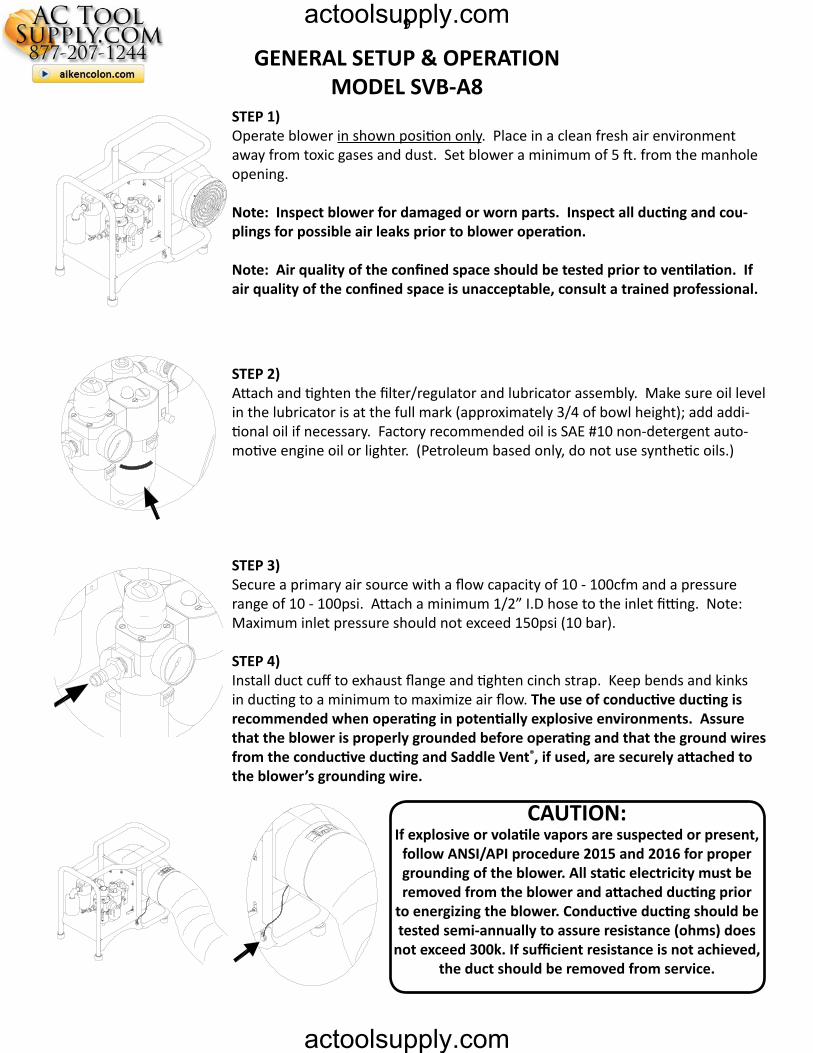
SteP 1)Operate blower in shown position only. Place in a clean fresh air environment away from toxic gases and dust. Set blower a minimum of 5 ft. from the manhole opening.
Note: Inspect blower for damaged or worn parts. Inspect all ducting and cou-plings for possible air leaks prior to blower operation.
Note: Air quality of the confined space should be tested prior to ventilation. If air quality of the confined space is unacceptable, consult a trained professional.
SteP 2)Attach and tighten the filter/regulator and lubricator assembly. Make sure oil level in the lubricator is at the full mark (approximately 3/4 of bowl height); add addi-tional oil if necessary. Factory recommended oil is SAE #10 non-detergent auto-motive engine oil or lighter. (Petroleum based only, do not use synthetic oils.)
SteP 3)Secure a primary air source with a flow capacity of 10 - 100cfm and a pressure range of 10 - 100psi. Attach a minimum 1/2” I.D hose to the inlet fitting. Note: Maximum inlet pressure should not exceed 150psi (10 bar).
STEP 4)Install duct cuff to exhaust flange and tighten cinch strap. Keep bends and kinks in ducting to a minimum to maximize air flow. The use of conductive ducting is recommended when operating in potentially explosive environments. Assure that the blower is properly grounded before operating and that the ground wires from the conductive ducting and Saddle Vent®, if used, are securely attached to the blower’s grounding wire.
cAUtion:If explosive or volatile vapors are suspected or present,
follow ANSI/API procedure 2015 and 2016 for proper grounding of the blower. All static electricity must be removed from the blower and attached ducting prior
to energizing the blower. Conductive ducting should be tested semi-annually to assure resistance (ohms) does
not exceed 300k. If sufficient resistance is not achieved, the duct should be removed from service.
GenerAl SetUP & oPerAtionmoDel SVB-A8
9actoolsupply.com
actoolsupply.com
GenerAl SetUP & oPerAtionmoDel SVB-A8
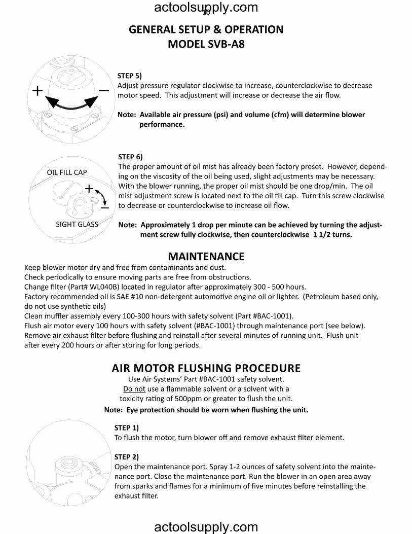
STEP 5)Adjust pressure regulator clockwise to increase, counterclockwise to decrease motor speed. This adjustment will increase or decrease the air flow.
Note: Available air pressure (psi) and volume (cfm) will determine blower performance.
STEP 6)The proper amount of oil mist has already been factory preset. However, depend-ing on the viscosity of the oil being used, slight adjustments may be necessary. With the blower running, the proper oil mist should be one drop/min. The oil mist adjustment screw is located next to the oil fill cap. Turn this screw clockwise to decrease or counterclockwise to increase oil flow.
Note: Approximately 1 drop per minute can be achieved by turning the adjust- ment screw fully clockwise, then counterclockwise 1 1/2 turns.
SIGHT GLASS
OIL FILL CAP
mAintenAnceKeep blower motor dry and free from contaminants and dust. Check periodically to ensure moving parts are free from obstructions.Change filter (Part# WL040B) located in regulator after approximately 300 - 500 hours. Factory recommended oil is SAE #10 non-detergent automotive engine oil or lighter. (Petroleum based only,do not use synthetic oils)Clean muffler assembly every 100-300 hours with safety solvent (Part #BAC-1001). Flush air motor every 100 hours with safety solvent (#BAC-1001) through maintenance port (see below). Remove air exhaust filter before flushing and reinstall after several minutes of running unit. Flush unit after every 200 hours or after storing for long periods.
Air motor FlUSHinG ProceDUreUse Air Systems’ Part #BAC-1001 safety solvent.
Do not use a flammable solvent or a solvent with a toxicity rating of 500ppm or greater to flush the unit.
Note: Eye protection should be worn when flushing the unit.
SteP 1)To flush the motor, turn blower off and remove exhaust filter element.
SteP 2)Open the maintenance port. Spray 1-2 ounces of safety solvent into the mainte-nance port. Close the maintenance port. Run the blower in an open area away from sparks and flames for a minimum of five minutes before reinstalling the exhaust filter.
10actoolsupply.com
actoolsupply.com
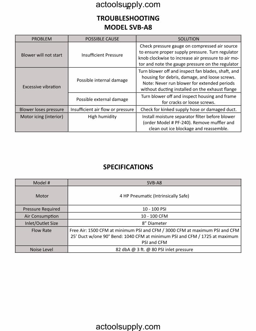
troUBleSHootinGmoDel SVB-A8
SPeciFicAtionS
PROBLEM POSSIBLE CAUSE SOLUTION
Blower will not start Insufficient Pressure
Check pressure gauge on compressed air source to ensure proper supply pressure. Turn regulator knob clockwise to increase air pressure to air mo-tor and note the gauge pressure on the regulator
Excessive vibrationPossible internal damage
Turn blower off and inspect fan blades, shaft, and housing for debris, damage, and loose screws.Note: Never run blower for extended periods
without ducting installed on the exhaust flange
Possible external damage Turn blower off and inspect housing and frame for cracks or loose screws.
Blower loses pressure Insufficient air flow or pressure Check for kinked supply hose or damaged duct.Motor icing (interior) High humidity Install moisture separator filter before blower
(order Model # PF-240). Remove muffler and clean out ice blockage and reassemble.
Model # SVB-A8
Motor 4 HP Pneumatic (Intrinsically Safe)
Pressure Required 10 - 100 PSIAir Consumption 10 - 100 CFMInlet/Outlet Size 8” Diameter
Flow Rate Free Air: 1500 CFM at minimum PSI and CFM / 3000 CFM at maximum PSI and CFM25’ Duct w/one 90° Bend: 1040 CFM at minimum PSI and CFM / 1725 at maximum
PSI and CFMNoise Level 82 dbA @ 3 ft. @ 80 PSI inlet pressure
11actoolsupply.com
actoolsupply.com
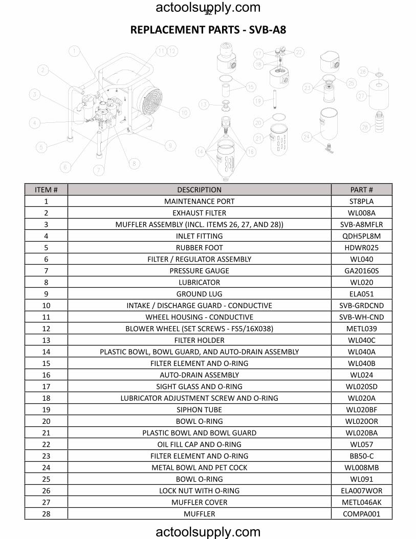
ITEM # DESCRIPTION PART #1 MAINTENANCE PORT ST8PLA2 EXHAUST FILTER WL008A3 MUFFLER ASSEMBLY (INCL. ITEMS 26, 27, AND 28)) SVB-A8MFLR4 INLET FITTING QDH5PL8M5 RUBBER FOOT HDWR0256 FILTER / REGULATOR ASSEMBLY WL0407 PRESSURE GAUGE GA20160S8 LUBRICATOR WL0209 GROUND LUG ELA051
10 INTAKE / DISCHARGE GUARD - CONDUCTIVE SVB-GRDCND11 WHEEL HOUSING - CONDUCTIVE SVB-WH-CND12 BLOWER WHEEL (SET SCREWS - FS5/16X038) METL03913 FILTER HOLDER WL040C14 PLASTIC BOWL, BOWL GUARD, AND AUTO-DRAIN ASSEMBLY WL040A15 FILTER ELEMENT AND O-RING WL040B16 AUTO-DRAIN ASSEMBLY WL02417 SIGHT GLASS AND O-RING WL020SD18 LUBRICATOR ADJUSTMENT SCREW AND O-RING WL020A19 SIPHON TUBE WL020BF20 BOWL O-RING WL020OR21 PLASTIC BOWL AND BOWL GUARD WL020BA22 OIL FILL CAP AND O-RING WL05723 FILTER ELEMENT AND O-RING BB50-C24 METAL BOWL AND PET COCK WL008MB25 BOWL O-RING WL09126 LOCK NUT WITH O-RING ELA007WOR27 MUFFLER COVER METL046AK28 MUFFLER COMPA001
rePlAcement PArtS - SVB-A812actoolsupply.com
actoolsupply.com
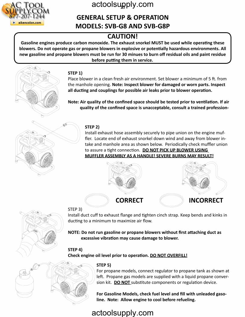
GenerAl SetUP & oPerAtionmoDelS: SVB-G8 AnD SVB-G8P
cAUtion!Gasoline engines produce carbon monoxide. The exhaust snorkel MUST be used while operating these
blowers. Do not operate gas or propane blowers in explosive or potentially hazardous environments. All new gasoline and propane blowers must be run for 30 minues to burn off residual oils and paint residue
before putting them in service.
SteP 1)Place blower in a clean fresh air environment. Set blower a minimum of 5 ft. from the manhole opening. Note: Inspect blower for damaged or worn parts. Inspect all ducting and couplings for possible air leaks prior to blower operation.
Note: Air quality of the confined space should be tested prior to ventilation. If air quality of the confined space is unacceptable, consult a trained profession-
SteP 2)Install exhaust hose assembly securely to pipe union on the engine muf-fler. Locate end of exhaust snorkel down wind and away from blower in-take and manhole area as shown below. Periodically check muffler union to assure a tight connection. Do not PicK UP BloWer USinG mUFFler ASSemBly AS A HAnDle! SeVere BUrnS mAy reSUlt!
correct incorrectSTEP 3)Install duct cuff to exhaust flange and tighten cinch strap. Keep bends and kinks in ducting to a minimum to maximize air flow.
NOTE: Do not run gasoline or propane blowers without first attaching duct as excessive vibration may cause damage to blower.
STEP 4)Check engine oil level prior to operation. Do not oVerFill!
STEP 5) For propane models, connect regulator to propane tank as shown at left. Propane gas models are supplied with a liquid propane conver-sion kit. Do not substitute components or regulation device.
For Gasoline Models, check fuel level and fill with unleaded gaso-line. Note: Allow engine to cool before refueling.
13actoolsupply.com
actoolsupply.com
STEP 6)Check engine intake filter periodically and replace if necessary.
SteP 7)Review and follow ALL safety precautions and run procedures found in the enclosed Briggs and Stratton/Honda manual prior to starting. (Some gasoline units are supplied with Honda engines as an option, Model SVB-G8H.)
SteP 8)Start engine by placing the throttle adjustment to idle and choke adjustment to “START” position. Pull start cord. Once started, return choke to “RUN” position. Caution: Do not exceed throttle “STOP” setting at maximum ad-justment as serious blower wheel and engine damage could result.
SHUtDoWn cAUtion:
Allow exhaust snorkel pipe to cool before removing from engine. Heat resistant gloves are recommended when handling the exhaust hose.
Insure that all workers have egressed the confined space.
Shut off blower. Do not move choke control to CHOKE to stop engine; backfire or engine damage may occur. Move throttle control to “SLOW” position; then move stop control to “STOP” position.
mAintenAnce
note: All maintenance should be completed with unit turned off and cooled down.
Keep blower motor dry and free from contaminants and dust. Engines stored over 30 days need to be protected or drained of fuel to prevent gum from forming in fuel system.
Check oil level and intake filters regularly. Be sure oil level is full and filters are well maintained. Check oil level every 5 hours or daily before staring engine.
PROBLEM POSSIBLE CAUSE SOLUTION
Excessive Vibration
Air intake blocked Turn blower off and clear debris from intake
Possible internal damage
Turn blower off and inspect fan blades, housing, and shaft for debris, damage, and loose screws.
NOTE: Never run blower without installing duct on exhaust flange.
Possible external damage Turn fan off and inspect housing and frame for cracks or loose screws.
Engine will not startNo fuel Refuel
Check propane hose connection.Fouled or faulty spark plug Remove, clean, re-gap, or replace spark plug.
troUBleSHootinG
14actoolsupply.com
actoolsupply.com
SPeciFicAtionS
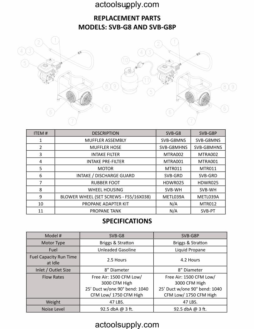
rePlAcement PArtSmoDelS: SVB-G8 AnD SVB-G8P
ITEM # DESCRIPTION SVB-G8 SVB-G8P1 MUFFLER ASSEMBLY SVB-G8MNS SVB-G8MNS2 MUFFLER HOSE SVB-G8MHNS SVB-G8MHNS3 INTAKE FILTER MTRA002 MTRA0024 INTAKE PRE-FILTER MTRA001 MTRA0015 MOTOR MTR011 MTR0116 INTAKE / DISCHARGE GUARD SVB-GRD SVB-GRD7 RUBBER FOOT HDWR025 HDWR0258 WHEEL HOUSING SVB-WH SVB-WH9 BLOWER WHEEL (SET SCREWS - FS5/16X038) METL039A METL039A
10 PROPANE ADAPTER KIT N/A MTR01211 PROPANE TANK N/A SVB-PT
Model # SVB-G8 SVB-G8PMotor Type Briggs & Stratton Briggs & Stratton
Fuel Unleaded Gasoline Liquid PropaneFuel Capacity Run Time
at Idle 2.5 Hours 4.2 Hours
Inlet / Outlet Size 8” Diameter 8” DiameterFlow Rates Free Air: 1500 CFM Low/
3000 CFM High25’ Duct w/one 90° bend: 1040
CFM Low/ 1750 CFM High
Free Air: 1500 CFM Low/3000 CFM High
25’ Duct w/one 90° bend: 1040 CFM Low/ 1750 CFM High
Weight 47 LBS. 47 LBS.Noise Level 92.5 dbA @ 3 ft. 92.5 dbA @ 3 ft.
15actoolsupply.com
actoolsupply.com
WArrAnty DiSclAimerAir Systems’ manufactured equipment is warranted to the original user against defects in workmanship or ma-terials under normal use for one year from the date of purchase. Any part which is determined by Air Systems
to be defecti ve in material or workmanship will be, as the exclusive remedy, repaired or replaced at Air Sys-tems’ opti on. This warranty does not apply to electrical systems or electronic components. Electrical parts are warranted, to the original user, for 90 days from the date of sale. During the warranty period, electrical com-
ponents will be repaired or replaced at Air Systems’ opti on.
no otHer WArrAnty, eXPreSSeD or imPlieD, AS to DeScriPtion, QUAlity, mercHAntABility, FitneSS For A PArticUlAr PUrPoSe, or Any otHer mAtter iS GiVen By Air SyStemS in connection Here-
WitH. UnDer no circUmStAnceS SHAll tHe Seller Be liABle For loSS oF ProFitS, Any otHer Direct or inDirect coStS, eXPenSeS, loSSeS, or DAmAGeS AriSinG oUt oF DeFectS in, or FAilUre oF tHe
ProDUct or Any PArt tHereoF.
The purchaser shall be solely responsible for compliance with all applicable Federal, State and Local OSHA and/or MSHA requirements. Although Air Systems Internati onal believes that its
products, if operated and maintained as shipped from the factory and in accordance with our “operati ons manual”, conform to OSHA and/or MSHA requirements, there are no implied or expressed warranti es of such compliance extending beyond the limited warranty described herein. Product designs and specifi cati ons are
subject to change without noti ce. Rev. 2, 12/98
Air leaks are not covered under warranty except when they result from a defecti ve system component, i.e. an on/off valve or regulator or upon initi al delivery due to poor workmanship. Air leaks due to poor delivery or
damage will be covered under delivery claims. Minor air leaks are part of routi ne service and maintenance and are the responsibility of the customer just as are fi lters and oil changes.
actoolsupply.com
actoolsupply.com


![1 Full-genome characterization of G8P[8] rotavirus emerged among](https://img.pdfslide.us/doc/110x75/589444131a28abb0138b55db/1-full-genome-characterization-of-g8p8-rotavirus-emerged-among-.jpg)