Embed Size (px)
Citation preview

FILE NO. SVM-12029
SERVICE MANUAL
AIR CONDITIONERSPLIT WALL TYPE
August, 2012
RAS-10N3KV-E / RAS-10N3AV-E
SWING
FANFIX
QUIET
Hi POWER
ONE-T OUCH
COMFORTSLEEP

CONTENTS
1. SAFETY PRECAUTIONS .......................................................................... 2
2. SPECIFICATIONS ..................................................................................... 4
3. REFRIGERANT R410A ............................................................................. 6
4. CONSTRUCTION VIEWS ........................................................................ 14
5. WIRING DIAGRAM .................................................................................. 16
6. SPECIFICATIONS OF ELECTRICAL PARTS ......................................... 18
7. REFRIGERANT CYCLE DIAGRAM ........................................................ 19
8. CONTROL BLOCK DIAGRAM ................................................................ 21
9. OPERATION DESCRIPTION................................................................... 23
10. INSTALLATION PROCEDURE ................................................................ 46
11. HOW TO DIAGNOSE THE TROUBLE ...................................................... 59
12. HOW TO REPLACE THE MAIN PARTS................................................... 79
13. EXPLODED VIEWS AND PARTS LIST ................................................... 88
– 1 –
FILE NO. SVM-12029

– 2 –
FILE NO. SVM-12029
For general public usePower supply cord of parts of appliance for outdoor use shall be at least polychloroprene sheathed flexible cord
(design H07RN-F) or cord designation 60245 IEC66 (1.5 mm2 or more). (Shall be installed in accordance with national
wiring regulations.)
CAUTION
New Refrigerant Air Conditioner Installation
• THIS AIR CONDITIONER ADOPTS THE NEW HFC REFRIGERANT (R410A) WHICH DOES NOT DESTROY
OZONE LAYER.
R410A refrigerant is apt to be affected by impurities such as water, oxidizing membranes, and oils because the
pressure of R410A refrigerant is approx. 1.6 times of refrigerant R22. As well as the adoption of this new refrigerant,
refrigerating machine oil has also been changed. Therefore, during installation work, be sure that water, dust,
former refrigerant, or refrigerating machine oil does not enter the refrigeration cycle of a new-refrigerant air
conditioner. To avoid mixing refrigerant and refrigerating machine oil, the sizes of charging port connecting port
connecting sections on the main unit are different from those for the conventional refrigerant, and different size tools
are also required. For connecting pipes, use new and clean piping materials with highpressure withstand
capabilities, designed for R410A only, and ensure that water or dust does not enter. Moreover, do not use any
existing piping as its pressure withstand may be insufficient and may contain impurities.
CAUTION
To disconnect the appliance from the main power supply
This appliance must be connected to the main power supply be means of a circuit breaker or a switch with a contact
separation of at least 3 mm in all poles.
The installation circuit breaker must be used specified for the power supply line of this air conditioner.
DANGER
• FOR USE BY QUALIFIED PERSONS ONLY.
• TURN OFF MAIN POWER SUPPLY BEFORE ATTEMPTING ANY ELECTRICAL WORK. MAKE SORE ALL POWER
SWITCHES ARE OFF FAILURE TO DO SO MAY CAUSE ELECTRIC SHOCK.
• CONNECT THE CONNECTING CABLE CORRECTLY. IF THE CONNECTING CABLE IS CONNECTED WRONGLY,
ELECTRIC PARTS MAY BE DAMAGED.
• CHECK THE EARTH WIRE THAT IT IS NOT BROKEN OR DISCONNECTED BEFORE INSTALLATION.
• DO NOT INSTALL NEAR CONCENTRATIONS OF COMBUSTIBLE GAS OR GAS VAPORS.
FAILURE TO FOLLOW THIS INSTRUCTION CAN RESULT IN FIRE OR EXPLOSION.
• TO PREVENT OVERHEATING THE INDOOR UNIT AND CAUSING A FIRE HAZARD, PLACE THE UNIT WELL
AWAY (MORE THAN 2 M) FROM HEAT SOURCES SUCH AS RADIATORS, HEATERS, FURNACE, STOVES, ETC.
• WHEN MOVING THE AIR CONDITIONER FOR INSTALLING IT IN ANOTHER PLACE AGAIN, BE VERY
CAREFUL NOT TO GET THE SPECIFIED REFRIGERANT (R410A) WITH ANY OTHER GASEOUS BODY INTO
THE REFRIGERATION CYCLE. IF AIR OR ANY OTHER GAS IS MIXED IN THE REFRIGERANT, THE GAS
PRESSURE IN THE REFRIGERATION CYCLE BECOMES ABNORMALLY HIGH AND IT RESULTINGLY CAUSES
BURST OF THE PIPE AND INJURIES ON PERSONS.
• IN THE EVENT THAT THE REFRIGERANT GAS LEAKS OUT OF THE PIPE DURING THE INSTALLATION WORK,
IMMEDIATELY LET FRESH AIR INTO THE ROOM. IF THE REFRIGERANT GAS IS HEATED BY FIRE OR
SOMETHING ELSE, IT CAUSES GENERATION OF POISONOUS GAS.
1. PRECAUTIONS FOR SAFETY

– 3 –
FILE NO. SVM-12029
WARNING
• Never modify this unit by removing any of the safety guards or bypass or bypass any of the safety
interlock switches.
• Do not install in a place which cannot bear the weight of the unit. Personal injury and property
damage can result if the unit falls.
• Before doing the electrical work, attach an approved plug to the power supply cord.
Also, make sure the equipment is properly earthed.
• Appliance shall be installed in accordance with national wiring regulations.
If you detect any damage, do not install the unit. Contact your TOSHIBA dealer immediately.
• Do not use any refrigerant different from the one specified for complement or replacement.
Otherwise, abnormally high pressure may by generated in the refrigeration cycle, which may result in a failure
or explosion of the product or an injury to your body.
CAUTION
• Exposure of unit to water or other moisture before installation could reslt in electric shock.
Do not store it in a wet basement or expose to rain or water.
• After unpacking the unit, examine it carefully for possible damage.
• Do not install in a place that can increase the vibration of the unit. Do not install in a place that can amplify the
noise level of the unit or where noise and discharged air might disturb neighbors.
• To avoid personal injury, be careful when handling parts with sharp edges.
• Please read this installation manual carefully before installing the unit. It contains further important instructions
for proper installation.
• The manufacturer shall not assume any liability for the damage caused by not observing the description of
this manual.

– 4 –
FILE NO. SVM-12029
2. SPECIFICATIONS
2-1. Specifications Unit model Indoor RAS-10N3KV-E
Outdoor RAS-10N3AV-E
Cooling capacity (kW) 2.5
Cooling capacity range (kW) 1.1 - 3.0
Heating capacity (kW) 3.2
Heating capacity range (kW) 0.9 - 4.1
Power supply 1Ph/50Hz/220-240V,1Ph/60Hz/220V
Electric Indoor Operation mode Cooling Heating
characteristic Running current (A) 0.16 - 0.14 0.16 - 0.14
Power consumption (W) 30 30
Power factor (%) 87 87
Outdoor Operation mode Cooling Heating
Running current (A) 3.44 - 3.16 3.96- 3.63
Power consumption (W) 720 830
Power factor (%) 95 95
Starting current (A) 4.12
COP (Cooling / Heating) 3.33 3.72 3.33/3.72
Operating Indoor High (Cooling / Heating) (dB-A) 38/40
noise Medium (Cooling / Heating) (dB-A) 33/35
Low (Cooling / Heating) (dB-A) 29/30
Outdoor (Cooling / Heating) (dB-A) 48/50
Indoor unit Unit model RAS-10N3KV-E
Dimension Height (mm) 250
Width (mm) 740
Depth (mm) 195
Net weight (kg) 8
Fan motor output (W) 20
Air flow rate (Cooling / Heating) (m3 / min) 8.7/9.6
Outdoor unit Unit model RAS-10N3AV-E
Dimension Height (mm) 530
Width (mm) 660
Depth (mm) 240
Net weight (kg) 27
Compressor Motor output (W) 750
Type Single rotary type with DC-inverter variable speed control
Model DA89X1C-23EZ
Fan motor output (W) 20
Air flow rate (Cooling / Heating) (m3 / min) 27/27
Piping Type Flare connection
connection Indoor unit Liquid side (mm) ∅6.35
Gas side (mm) ∅9.52
Outdoor unit Liquid side (mm) ∅6.35
Gas side (mm) ∅9.52
Maximum length (m) 10
Maximun charge-less length (m) 10
Maximum height difference (m) 8
Refrigerant Name of refrigerant R410A
Weight (kg) 0.63
Wiring Power supply 3 Wires: Includes earth (Outdoor)
connection Interconnection 4 Wires: Includes earth
Usable temperature range Indoor (Cooling / Heating) (oC) 21 - 32/Up to 27
Outdoor (Cooling / Heating) (oC) 15 - 43/-10 - 24
Accessory Indoor unit Installation plate 1
Wireless remote controller 1
batteries 2
Remote controller holder 1
Toshiba New IAQ filer 2
Mounting screw 6 (∅ 4 x 25L)
Flat head wood screw 2 (∅ 3.1 x 16L)
Installation manual 1
Owner's manual 1
Outdoor unit Drain nipple 1
Water proof rubber cap 2
* The specification may be subject to change without notice for purpose of improvement.

– 5 –
2-2. Operation Characteristic Curve
FILE NO. SVM-12029
< Cooling> < Heating>
2-3. Capacity Vari ati on Ratio According to Temperature
< Cooling> < Heating>
0
1
2
3
4
5
6
0 10 20 30 40 50 60 70 80 90 100 110 120
Compressor Speed ( rps)
Cur
rent
(A
)
0
1
2
3
4
5
6
0 10 20 30 40 50 60 70 80 90 100 110 120
Compressor Speed ( rps)
Cur
rent
(A
)Conditions
Indoor : DB 27oC/WB 19
oC
Outdoor : DB 35oC
Air Flow : High
Pipe Length : 5m
Voltage : 230V
Conditions
Indoor : DB 20oC
Outdoor : DB 7oC/WB 6
oC
Air Flow : High
Pipe Length : 5m
Voltage : 230V
50
55
60
65
70
75
80
85
90
95
100
105
32 33 34 35 36 37 38 39 40 41 42 43
Coolin
g C
apacity r
atio (
%)
Outside Temperature ( oC)
0
20
40
60
80
100
120
-10 -5 0 5 10
Heating C
apacity r
atio (
%)
Outside Temperature ( ºC)
Conditions
Indoor : DB 27oC/WB 19
oC
Indoor Air Flow : High
Pipe Length : 5m
Voltage : 230V
Capacity ratio 100% is 2.5kw
Conditions
Indoor : DB 20oC
Indoor Air Flow : High
Pipe Length : 5m
Voltage : 230V
– 6 –
3. REFRIGERANT R410A
This air conditioner adopts the new refrigerant HFC(R410A) which does not damage the ozone layer.
The working pressure of the new refrigerant R410Ais 1.6 times higher than conventional refrigerant(R22). The refrigerating oil is also changed inaccordance with change of refrigerant, so be carefulthat water, dust, and existing refrigerant or refrigerat-ing oil are not entered in the refrigerant cycle of theair conditioner using the new refrigerant duringinstallation work or servicing time.
The next section describes the precautions for airconditioner using the new refrigerant. Conforming tocontents of the next section together with thegeneral cautions included in this manual, performthe correct and safe work.
3-1. Safety During Installation/Servicing
As R410A’s pressure is about 1.6 times higher thanthat of R22, improper installation/servicing maycause a serious trouble. By using tools and materi-als exclusive for R410A, it is necessary to carry outinstallation/servicing safely while taking the followingprecautions into consideration.
1. Never use refrigerant other than R410A in an airconditioner which is designed to operate withR410A.
If other refrigerant than R410A is mixed, pressurein the refrigeration cycle becomes abnormallyhigh, and it may cause personal injury, etc. by arupture.
2. Confirm the used refrigerant name, and use toolsand materials exclusive for the refrigerant R410A.
The refrigerant name R410A is indicated on thevisible place of the outdoor unit of the air condi-tioner using R410A as refrigerant. To preventmischarging, the diameter of the service portdiffers from that of R22.
3. If a refrigeration gas leakage occurs duringinstallation/servicing, be sure to ventilate fully.
If the refrigerant gas comes into contact with fire,a poisonous gas may occur.
4. When installing or removing an air conditioner, donot allow air or moisture to remain in the refrig-eration cycle. Otherwise, pressure in the refrig-eration cycle may become abnormally high sothat a rupture or personal injury may be caused.
5. After completion of installation work, check tomake sure that there is no refrigeration gasleakage.
If the refrigerant gas leaks into the room, cominginto contact with fire in the fan-driven heater,space heater, etc., a poisonous gas may occur.
6. When an air conditioning system charged with alarge volume of refrigerant is installed in a smallroom, it is necessary to exercise care so that,even when refrigerant leaks, its concentrationdoes not exceed the marginal level.
If the refrigerant gas leakage occurs and itsconcentration exceeds the marginal level, anoxygen starvation accident may result.
7. Be sure to carry out installation or removalaccording to the installation manual.
Improper installation may cause refrigerationtrouble, water leakage, electric shock, fire, etc.
8. Unauthorized modifications to the air conditionermay be dangerous. If a breakdown occursplease call a qualified air conditioner technicianor electrician.
Improper repair’s may result in water leakage,electric shock and fire, etc.
3-2. Refrigerant Piping Installation
3-2-1. Piping Materials and Joints Used
For the refrigerant piping installation, copper pipesand joints are mainly used. Copper pipes and jointssuitable for the refrigerant must be chosen andinstalled. Furthermore, it is necessary to use cleancopper pipes and joints whose interior surfaces areless affected by contaminants.
1. Copper PipesIt is necessary to use seamless copper pipeswhich are made of either copper or copper alloyand it is desirable that the amount of residual oilis less than 40 mg/10 m. Do not use copperpipes having a collapsed, deformed or discoloredportion (especially on the interior surface).
Otherwise, the expansion valve or capillary tubemay become blocked with contaminants.
As an air conditioner using R410A incurs pres-sure higher than when using R22, it is necessaryto choose adequate materials.
Thicknesses of copper pipes used with R410Aare as shown in Table 3-2-1. Never use copperpipes thinner than 0.8 mm even when it isavailable on the market.
FILE NO. SVM-12029

– 7 –
Table 3-2-1 Thicknesses of annealed copper pipes
Nominal diameter
1/4
3/8
1/2
5/8
Outer diameter (mm)
6.35
9.52
12.70
15.88
Thickness (mm)
R410A R22
0.80 0.80
0.80 0.80
0.80 0.80
1.00 1.00
2. JointsFor copper pipes, flare joints or socket joints are used. Prior to use, be sure to remove all contaminants.
a) Flare Joints
Flare joints used to connect the copper pipes cannot be used for pipings whose outer diameter exceeds20 mm. In such a case, socket joints can be used.
Sizes of flare pipe ends, flare joint ends and flare nuts are as shown in Tables 3-2-3 to 3-2-6 below.
b) Socket Joints
Socket joints are such that they are brazed for connections, and used mainly for thick pipings whosediameter is larger than 20 mm.
Thicknesses of socket joints are as shown in Table 3-2-2.
Table 3-2-2 Minimum thicknesses of socket joints
Nominal diameter
1/4
3/8
1/2
5/8
Reference outer diameter ofcopper pipe jointed (mm)
6.35
9.52
12.70
15.88
Minimum joint thickness(mm)
0.50
0.60
0.70
0.80
3-2-2. Processing of Piping Materials
When performing the refrigerant piping installation, care should be taken to ensure that water or dust does notenter the pipe interior, that no other oil than lubricating oils used in the installed air-water heat pump is used,and that refrigerant does not leak. When using lubricating oils in the piping processing, use such lubricating oilswhose water content has been removed. When stored, be sure to seal the container with an airtight cap or anyother cover.
1. Flare processing procedures and precautionsa) Cutting the Pipe
By means of a pipe cutter, slowly cut the pipe so that it is not deformed.
b) Removing Burrs and Chips
If the flared section has chips or burrs, refrigerant leakage may occur.Carefully remove all burrs and clean the cut surface before installation.
c) Insertion of Flare Nut
FILE NO. SVM-12029

– 8 –
AØD
d) Flare Processing
Make certain that a clamp bar and copperpipe have been cleaned.
By means of the clamp bar, perform the flareprocessing correctly.
Use either a flare tool for R410A or conven-tional flare tool.
Flare processing dimensions differ accordingto the type of flare tool. When using a con-ventional flare tool, be sure to secure “dimen-sion A” by using a gauge for size adjustment. Fig. 3-2-1 Flare processing dimensions
Table 3-2-3 Dimensions related to flare processing for R410A
Nominaldiameter
1/4
3/8
1/2
5/8
Outerdiameter
(mm)
6.35
9.52
12.70
15.88
Thickness(mm)
0.8
0.8
0.8
1.0
A (mm)
Flare tool for R410Aclutch type
0 to 0.5
0 to 0.5
0 to 0.5
0 to 0.5
Conventional flare tool
Clutch type Wing nut type
1.0 to 1.5 1.5 to 2.0
1.0 to 1.5 1.5 to 2.0
1.0 to 1.5 2.0 to 2.5
1.0 to 1.5 2.0 to 2.5
Table 3-2-4 Dimensions related to flare processing for R22
Nominaldiameter
1/4
3/8
1/2
5/8
Outerdiameter
(mm)
6.35
9.52
12.70
15.88
Thickness(mm)
0.8
0.8
0.8
1.0
A (mm)
Flare tool for R22clutch type
0 to 0.5
0 to 0.5
0 to 0.5
0 to 0.5
Conventional flare tool
Clutch type Wing nut type
0.5 to 1.0 1.0 to 1.5
0.5 to 1.0 1.0 to 1.5
0.5 to 1.0 1.5 to 2.0
0.5 to 1.0 1.5 to 2.0
Table 3-2-5 Flare and flare nut dimensions for R410A
Nominaldiameter
1/4
3/8
1/2
5/8
Outer diameter(mm)
6.35
9.52
12.70
15.88
Thickness(mm)
0.8
0.8
0.8
1.0
Dimension (mm)
A B C D
9.1 9.2 6.5 13
13.2 13.5 9.7 20
16.6 16.0 12.9 23
19.7 19.0 16.0 25
Flare nut width(mm)
17
22
26
29
FILE NO. SVM-12029

– 9 –
43˚ to 45˚
45˚ to 46˚
B A C D
Table 3-2-6 Flare and flare nut dimensions for R22
Nominaldiameter
1/4
3/8
1/2
5/8
3/4
Outer diameter(mm)
6.35
9.52
12.70
15.88
19.05
Thickness(mm)
0.8
0.8
0.8
1.0
1.0
Dimension (mm)
A B C D
9.0 9.2 6.5 13
13.0 13.5 9.7 20
16.2 16.0 12.9 20
19.7 19.0 16.0 23
23.3 24.0 19.2 34
Flare nut width(mm)
17
22
24
27
36
Fig. 3-2-2 Relations between flare nut and flare seal surface
2. Flare Connecting Procedures and Precautionsa) Make sure that the flare and union portions do not have any scar or dust, etc.
b) Correctly align the processed flare surface with the union axis.
c) Tighten the flare with designated torque by means of a torque wrench. The tightening torque for R410A isthe same as that for conventional R22. Incidentally, when the torque is weak, the gas leakage may occur.
When it is strong, the flare nut may crack and may be made non-removable. When choosing the tighten-ing torque, comply with values designated by manufacturers. Table 3-2-7 shows reference values.
NOTE :When applying oil to the flare surface, be sure to use oil designated by the manufacturer.If any other oil is used, the lubricating oils may deteriorate and cause the compressor to burn out.
Table 3-2-7 Tightening torque of flare for R410A [Reference values]
Nominaldiameter
1/4
3/8
1/2
5/8
Outer diameter(mm)
6.35
9.52
12.70
15.88
Tightening torqueN•m (kgf •cm)
14 to 18 (140 to 180)
33 to 42 (330 to 420)
50 to 62 (500 to 620)
63 to 77 (630 to 770)
Tightening torque of torquewrenches available on the market
N•m (kgf •cm)
16 (160), 18 (180)
42 (420)
55 (550)
65 (650)
FILE NO. SVM-12029

– 10 –
3-3. Tools
3-3-1. Required Tools
The service port diameter of packed valve of the outdoor unit in the air-water heat pump using R410A ischanged to prevent mixing of other refrigerant. To reinforce the pressure-resisting strength, flare processingdimensions and opposite side dimension of flare nut (For Ø12.7 copper pipe) of the refrigerant piping arelengthened.
The used refrigerating oil is changed, and mixing of oil may cause a trouble such as generation of sludge,clogging of capillary, etc. Accordingly, the tools to be used are classified into the following three types.
1. Tools exclusive for R410A (Those which cannot be used for conventional refrigerant (R22))
2. Tools exclusive for R410A, but can be also used for conventional refrigerant (R22)
3. Tools commonly used for R410A and for conventional refrigerant (R22)
The table below shows the tools exclusive for R410A and their interchangeability.
Tools exclusive for R410A (The following tools for R410A are required.)
Tools whose specifications are changed for R410A and their interchangeability
No.
1
2
3
4
5
6
7
8
9
10
Used tool
Flare tool
Copper pipe gauge foradjusting projectionmargin
Torque wrench(For Ø12.7)
Gauge manifold
Charge hose
Vacuum pump adapter
Electronic balance forrefrigerant charging
Refrigerant cylinder
Leakage detector
Charging cylinder
Usage
Pipe flaring
Flaring byconventional flare tool
Connection of flare nut
Evacuating, refrigerantcharge, run check, etc.
Vacuum evacuating
Refrigerant charge
Refrigerant charge
Gas leakage check
Refrigerant charge
R410Aair-water heat pump installation
Existence ofnew equipmentfor R410A
Yes
Yes
Yes
Yes
Yes
Yes
Yes
Yes
(Note 2)
Whether conven-tional equipmentcan be used
*(Note 1)
*(Note 1)
×
×
×××××
Conventional air-waterheat pump installation
Whether new equipmentcan be used withconventional refrigerant
*(Note 1)
×
×
×
×(Note 1) When flaring is carried out for R410A using the conventional flare tools, adjustment of projection
margin is necessary. For this adjustment, a copper pipe gauge, etc. are necessary.(Note 2) Charging cylinder for R410A is being currently developed.
General tools (Conventional tools can be used.)
In addition to the above exclusive tools, the following equipments which serve also for R22 are necessaryas the general tools.
1. Vacuum pumpUse vacuum pump by attachingvacuum pump adapter.
2. Torque wrench (For Ø6.35, Ø9.52)
3. Pipe cutter
4. Reamer
5. Pipe bender
6. Level vial
7. Screwdriver (+, –)
8. Spanner or Monkey wrench
9. Hole core drill (Ø65)
10. Hexagon wrench(Opposite side 4mm)
11. Tape measure
12. Metal saw
Also prepare the following equipments for other installation method and run check.
1. Clamp meter
2. Thermometer
3. Insulation resistance tester
4. Electroscope
FILE NO. SVM-12029

– 11 –
Connect the charge hose to packed valve service port at the outdoor unit’s gas side.
Recover the refrigerant, and check no refrigerant remains in the equipment.
(For refrigerant charging, see the figure below.)
Connect the charge hose to the vacuum pump adapter.
Open fully both packed valves at liquid and gas sides.
Place the handle of the gauge manifold Low in the fully opened position, and turn on the vacuum pump’s power switch. Then, evacuating the refrigerant in the cycle.
When the compound gauge’s pointer has indicated –0.1 Mpa (–76 cmHg), place the handle Low in the fully closed position, and turn off the vacuum pump’s power switch.
Keep the status as it is for 1 to 2 minutes, and ensure that the compound gauge’s pointer does not return.
Set the refrigerant cylinder to the electronic balance, connect the connecting hose to the cylinder and the connecting port of the electronic balance, and charge liquid refrigerant .
(Indoor unit)(Outdoor unit)
Opened
Opened
Refrigerant cylinder (with siphon)
Check valve
Open/close valve for charging
Electronic balance for refrigerant charging
Opened
Closed
Service port
3-4. Recharging of Refrigerant
When it is necessary to recharge refrigerant, charge the specified amount of new refrigerant according to thefollowing steps.
1. Never charge refrigerant exceeding the specified amount.
2. If the specified amount of refrigerant cannot be charged, charge refrigerant bit by bit in COOL mode.
3. Do not carry out additional charging.
When additional charging is carried out if refrigerant leaks, the refrigerant composition changes in therefrigeration cycle, that is characteristics of the air conditioner changes, refrigerant exceeding thespecified amount is charged, and working pressure in the refrigeration cycle becomes abnormally highpressure, and may cause a rupture or personal injury.
Fig. 3-4-1 Configuration of refrigerant charging
FILE NO. SVM-12029

– 12 –
Gauge manifold
[ Cylinder with siphon ] [ Cylinder without siphon ]
OUTDOOR unitGauge manifold
OUTDOOR unit
Refrigerantcylinder
Electronic balance
Refrigerantcylinder
Electronic balance
Siphon
1. Be sure to make setting so that liquid can be charged.
2. When using a cylinder equipped with a siphon, liquid can be charged without turning it upside down.
It is necessary for charging refrigerant under condition of liquid because R410A is mixed type of refrigerant.Accordingly, when charging refrigerant from the refrigerant cylinder to the equipment, charge it turning thecylinder upside down if cylinder is not equipped with siphon.
R410A refrigerant is HFC mixed refrigerant.Therefore, if it is charged with gas, the composi-tion of the charged refrigerant changes and thecharacteristics of the equipment varies.
3-5. Brazing of Pipes
3-5-1. Materials for Brazing
1. Silver brazing fillerSilver brazing filler is an alloy mainly composedof silver and copper. It is used to join iron, copperor copper alloy, and is relatively expensive thoughit excels in solderability.
2. Phosphor bronze brazing fillerPhosphor bronze brazing filler is generally usedto join copper or copper alloy.
3. Low temperature brazing fillerLow temperature brazing filler is generally calledsolder, and is an alloy of tin and lead. Since it isweak in adhesive strength, do not use it forrefrigerant pipes.
1. Phosphor bronze brazing filler tends to reactwith sulfur and produce a fragile compoundwater solution, which may cause a gasleakage. Therefore, use any other type ofbrazing filler at a hot spring resort, etc., andcoat the surface with a paint.
2. When performing brazing again at time ofservicing, use the same type of brazing filler.
3-5-2. Flux
1. Reason why flux is necessary• By removing the oxide film and any foreign
matter on the metal surface, it assists the flowof brazing filler.
• In the brazing process, it prevents the metalsurface from being oxidized.
• By reducing the brazing filler’s surface tension,the brazing filler adheres better to the treatedmetal.
Fig. 3-4-2
FILE NO. SVM-12029

– 13 –
Nitrogen gascylinder
Pipe
Flow meterM
Stop valve
From Nitrogen cylinder
Nitrogen gas
Rubber plug
2. Characteristics required for flux• Activated temperature of flux coincides with the
brazing temperature.
• Due to a wide effective temperature range, fluxis hard to carbonize.
• It is easy to remove slag after brazing.
• The corrosive action to the treated metal andbrazing filler is minimum.
• It excels in coating performance and is harm-less to the human body.
As the flux works in a complicated manner asdescribed above, it is necessary to select anadequate type of flux according to the type andshape of treated metal, type of brazing filler andbrazing method, etc.
3. Types of flux• Noncorrosive flux
Generally, it is a compound of borax and boricacid.It is effective in case where the brazing tem-perature is higher than 800°C.
• Activated flux
Most of fluxes generally used for silver brazingare this type.It features an increased oxide film removingcapability due to the addition of compoundssuch as potassium fluoride, potassium chlorideand sodium fluoride to the borax-boric acidcompound.
4. Piping materials for brazing and usedbrazing filler/flux
1. Do not enter flux into the refrigeration cycle.
2. When chlorine contained in the flux remainswithin the pipe, the lubricating oil deteriorates.Therefore, use a flux which does not containchlorine.
3. When adding water to the flux, use waterwhich does not contain chlorine (e.g. distilledwater or ion-exchange water).
4. Remove the flux after brazing.
3-5-3. Brazing
As brazing work requires sophisticated techniques,experiences based upon a theoretical knowledge, itmust be performed by a person qualified.
In order to prevent the oxide film from occurring inthe pipe interior during brazing, it is effective toproceed with brazing while letting dry Nitrogen gas(N2) flow.
Never use gas other than Nitrogen gas.
1. Brazing method to prevent oxidation1) Attach a reducing valve and a flow-meter to
the Nitrogen gas cylinder.
2) Use a copper pipe to direct the piping mate-rial, and attach a flow-meter to the cylinder.
3) Apply a seal onto the clearance between thepiping material and inserted copper pipe forNitrogen in order to prevent backflow of theNitrogen gas.
4) When the Nitrogen gas is flowing, be sure tokeep the piping end open.
5) Adjust the flow rate of Nitrogen gas so that itis lower than 0.05 m3/Hr or 0.02 MPa(0.2kgf/cm2) by means of the reducing valve.
6) After performing the steps above, keep theNitrogen gas flowing until the pipe cools downto a certain extent (temperature at whichpipes are touchable with hands).
7) Remove the flux completely after brazing.
Fig. 3-5-1 Prevention of oxidation during brazing
Piping material
Copper - Copper
Copper - Iron
Iron - Iron
Used brazing filler
Phosphor copper
Silver
Silver
Used flux
Do not use
Paste flux
Vapor flux
FILE NO. SVM-12029

– 14 –
FILE NO. SVM-12029
4. CONSTRUCTION VIEWS
4-1. Indoor Unit
235
135
38
45
135
45
26
16
5
25
0
90
40
90
290
1
49
17.5 63
18
1
72
Wireless remote controller
Remote controller holder
57
Hanger
Hanger Hanger
Installation plate outline
Center line
8~ 10)For stud bold (
For stud bold ( 6)215
145 145
215
235
605
(Flare 6.35)Drain hose (0.5m)
Hanger
Connecting pipe (0.37m)
Connecting pipe (0.37m)(Flare 9.52)
500105 135
55 60 55
50
50
60
Knock out system
8
52
58
195 Front panel
Knock out system
Grille Inlet
86
0
Air filter Heat exchangerAir inlet
Air outlet
740
25
0

FILE NO. SVM-12029
− 15 −
4-2. Outdoor Unit
CL
CL
280
400

– 16 –
FILE NO. SVM-12029
5. WIRING DIAGRAM
5-1. Indoor Unit
Outdoor Terminal Block
POWER SUPPLY
Indoor Terminal Block
1 2 3
1 2 3 HeatExchanger2
BL
K
WH
I
RE
D
GR
N&
YE
L
(From outdoor Unit)
3 1
1 1
2 2
3 3
4 4
5 5
6 6
7 7
8 8
1 1
2 2
3 3
4 4
5 5
6 6
1
4
(WHI)CN25 (YEL)
CN20
Wirele
ss U
nit A
ssem
bly
WP
-017
WHI
BLU
BLUBLU
BLUBLU
1 1
2 2
1 1
2 2
(BLU)CN62
(WHI)CN61 Thermo Sensor
(TA)
Heat Exchanger Sensor(TC)
1 1
2 2
3 3
4 4
5 5
1 1
2 2
3 3
4 4
5 5
1 1
2 2
3 3
1 1
2 2
3 3
4 4
5 5
6 6
5
4 4
3 3
2 2
1 1
(WHI)CN32
(WHI)CN33
(WHI)CN31
WHI
YEL
YEL
YELYEL
Louver Motor
1
2
3
4
(WHI)CN22
Color indication
BRW:BROWNYEL:YELLOWBLK:BLACKRED:REDBLU:BLUEWHI:WHITE GRN & YEL:GREEN & YELLOW
Fan Motor
AC Motor
5
Po
we
r S
up
ply
Circu
it
Main P.C BoardWP-020
DC5V
DC12V
3
T3
.15
A
Fu
se
F0
1
CN01 CN51
Varistor LineFilter
Check Items
OPERATION indicator
Check to see if the OPERATION indicator goes on & off when
the main switch or circuit breakers turned on,or power cord is
plugged in the wall outlet.
Check for the voltage between and is 220 to 240VAC.
Check Varistor if the fuse is open.Fuse3.15A
DC5V
Terminalblock
Diagnosis result
1
2
3
4
1 2
Check for the voltage between and is 15 to 60VDC. 2 3
Check for the voltage between and terminal of CN20. 2 3
Quick check for diagnosing faults
+

– 1
7 –
FILE
NO
. SVM
-12029
5-2. Outdoor Unit
(From Main Line)

– 18 –
FILE NO. SVM-12029
6. SPECIFICATION OF ELECTRICAL PARTS
6-1. Indoor Unit
6-2. Outdoor Unit
No. Parts name Type Specifications
AFN-220-20-4D
AC 240V, 20W
2 Room temp. sensor (TA-sensor) ( - ) 10kΩ at 25°C
3 Heat exchanger temp. sensor (TC-sensor) ( - ) 10kΩ at 25°C
4 Louver motor MP24ZCT Output (Rated) 1W, 16 poles, DC12V
No. Parts name Type Specifications
L = 19mH, 10A
2 Outdoor fan motor WLF-240-20A-1 AC 240V, 20W
3 Suction temp. sensor (TS sensor) (Inverter attached) 10kΩ (25°C)
4 Discharge temp. sensor (TD sensor) (Inverter attached) 62kΩ (20°C)
5 Outside air temp. sensor (TO sensor) (Inverter attached) 10kΩ (25°C)
6 Heat exchanger temp. sensor (TE sensor) (Inverter attached) 10kΩ (25°C)
Reactor1
1 Fan motor (for indoor)
20A, AC250V
DA89X1C-23EZ
STF
3-phases 4-poles 750W
AC220-240VCoil for 4-way valve
Compressor
Terminal block (5P)7
8
9
CH-69

7. REFRIGERANT CYCLE DIAGRAM
7-1. Refrigerant Cycle Diagram
NOTE :• The maximum pipe length of this air conditioner is 10 m. The addition charging of refrigevant is
Deoxidized copper pipe Outer dia. : 9.52mm Thickness : 0.8mm
NOTE : Gas leak check positionRefrigerant flow (Cooling)Refrigerant flow (Heating)
INDOOR UNIT T1
TO
Temp. measurement
TC
TA
Indoor heatexchanger
Cross flow fan
Deoxidized copper pipe Outer dia. : 6.35mm Thickness : 0.8mm
Sectional shapeof heat insulator
Allo
wab
le h
eigh
tdi
ffere
nce
: 10m
Allo
wab
le p
ipe
leng
th
P Pressure measurementGauge attaching portVacuum pump connecting port
TD
4-way valve(STF-0108Z)
CompressorDA89X1C-23E2
T2
Outdoor heat exchanger
Temp. measurement
Propeller fan Refrigerant amount : 0.63kg
OUTDOOR UNIT
Muffler
Muffler
Ø1.0 x 600
T E
Ø1.0 x 600
Min. : 2mChargeless : 10m
Max. : 10m
unnecessary because this air condition is design with charge-less specitication.
FILE NO. SVM-12029
– 19 –

FILE NO. SVM-12029
7-2. Operation Data
<Cooling>
Tempeature Standard Heat exchanger Indoor Outdoor Compressor
condition(°C) pressure pipe temp. fan mode fan mode revolution
Indoor Outdoor P (MPa) T1 (°C) T2 (°C) (rps)
27/19 35/- 0.9 to 1.1 9 to 11 47 to 49 High High 54
<Heating>
Tempeature Standard Heat exchanger Indoor Outdoor Compressor
condition(°C) pressure pipe temp. fan mode fan mode revolution
Indoor Outdoor P (MPa) T1 (°C) T2 (°C) (rps)
20/- 7/6 2.4 to 2.6 43 to 45 0 to 3 High High 68
NOTES :
1. Measure surface temperature of heat exchanger pipe around center of heat exchaner path U bent.
(Thermistor themometer)
2. Connecting piping condition 5 m
– 20 –

FILE NO. SVM-12029
– 21 –
8. CONTROL BLOCK DIAGRAM
8-1. Indoor Unit
M.C.U. Indoor Unit Control Unit
Power Supply(From outdoor unit) Serial Signal Communication
(Operation Command and Information)
Serial Signal Transmitter/Receiver
Converter(D.C circuit)
Noise Filter
IndoorFan Motor
LouverMotor
Louver MotorDrive Control
Indoor FanMotor Control
Initializing Circuit
Clock FrequencyOscillator Circuit
Power SupplyCircuit
Infrared Rays, 36.7kHzRemote Controller
Thermo. Setting
Fan Speed Selection
ON TIMER Setting
OFF TIMER Setting
Louver AUTO Swing
Louver Direction Setting
QUIET
Operation Mode SelectionAUTO, COOL, DRY, HEAT
REMOTE CONTROLLER
ECO
Hi-POWER
Heat Exchanger Sensor (Tc)
Room Temperature Sensor (Ta)
Infrared Rays Signal Receiverand Indication
Functions
• Cold draft preventing Function
• 3-minute Delay at Restart for Compressor
• Fan Motor Starting Control
• Processing (Temperature Processing)
• Timer
• Serial Signal Communication
• Clean Function
Operation [ ]
COMFORT SLEEP

– 2
2 –
FILE
NO
. SVM
-12029
8-2. Outdoor U
nit (Inve
rter Assem
bly)
For INDOOR UNIT
signal
Noisefilter
Inputcurrentsensor
Converter(AC DC)
P.C.B (MCC 5009)
Overcurrentsensor
Gate drivecircuit
Rotor positiondetect circuit
Relay
Fanmotor
4wayValve
Relay
High power factorcorrection circuit
1. PWM synthesis function2. Input current release control3. IGBT over-current detect control4. Outdoor fan control5. High power factor correction control6.Signal communication to indoor unit M. C. U
M. C. U
Inverter(DC AC)
Compressor
Dischargetemp. sensor
Outdoor airtemp. sensor
Heat Exchangertemp. sensor
MICRO-COMPUTER BLOCK DIAGRAM
(From Main Line)
Power Supply

− 23 −
9. OPERATION DESCRIPTION
9-1. Outline of Air Conditioner Control
This air conditioner is a capacity-variable type airconditioner, which uses AC motor both the indoor fan motor and the outdoor fan motor. And the capacity-proportional control compressor which can change themotor speed in the range from 22 to 83 rps ismounted. The AC motor drive circuit is mounted to theindoor unit. The compressor and the inverter is mountedto the outdoor unit.
The entire air conditioner is mainly controlled by theindoor unit controller.
The indoor unit controller drives the indoor fan motorbased upon command sent from the remote controller,and transfers the operation command to the outdoorunit controller.
The outdoor unit controller receives operation com-mand from the indoor unit side, and controls the
of the compressor motor, the outdoor unit controller controls speed of the compressor motor by controlling
And then, the outdoor unit controller transfers reverselythe operating status information of the outdoor unit tocontrol the indoor unit controller.
As the compressor adopts four -pole brushlessDC motor , the frequency of the supply powerfrom in verter to compressor is two-times cyclesof the actual number of revolution.
1. Role of indoor unit controller
The indoor unit controller judges the operationcommands from the remote controller and assumesthe following functions.
• Judgment of suction air temperature of the indoorheat exchanger by using the indoor temp. sensor.(TA sensor)
• Judgment of the indoor heat exchanger tempera-ture by using heat exchanger sensor (TC sensor)(Prevent-freezing control, etc.)
• Louver motor control
• Indoor fan motor operation control
• LED (Light Emitting Diode) display control
• Transferring of operation command signal (Serialsignal) to the outdoor unit
• Reception of information of operation status(Serial signal including outside temp. data) to theoutdoor unit and judgment/display of error
2. Role of outdoor unit controller
Receiving the operation command signal (Serialsignal) from the indoor unit controller, the outdoorunit performs its role.
• Compressor operation control
• 4-way valve controlOperations followed to judgmentof serial signal from indoor side
.
• Detection of inverter input current and currentrelease operation
• Over-current detection and prevention operationto IGBT module (Compressor stop function)
• Compressor and outdoor fan stop function whenserial signal is off (when the serial signal does notreach the board assembly of outdoor control bytrouble of the signal system)
• Transferring of operation information (Serialsignal) from outdoor unit controller to indoor unitcontroller
• Detection of outdoor temperature and operationrevolution control
• Defrost control in heating operation (Temp.measurement by outdoor heat exchanger andcontrol for 4-way valve and outdoor fan)
3. Contents of operation command signal(Serial signal) from indoor unit controller to
outdoor unit controller
The following three types of signals are sent fromthe indoor unit controller.
• Operation mode set on the remote controller
• Compressor revolution command signal definedby indoor temperature and set temperature(Correction along with variation of room tempera-ture and correction of indoor heat exchangertemperature are added.)
• Temperature of indoor heat exchanger
• For these signals ([Operation mode] and [Com-pressor revolution] indoor heat exchanger tem-perature), the outdoor unit controller monitors theinput current to the inverter, and performs thefollowed operation within the range that currentdoes not exceed the allowable value.
4. Contents of operation command signal(Serial signal) from outdoor unit controller
to indoor unit controller
The following signals are sent from the outdoor unitcontroller.
• The current operation mode
• The current compressor revolution
• Outdoor temperature
• Existence of protective circuit operation
For transferring of these signals, the indoor unitcontroller monitors the contents of signals, andjudges existence of trouble occurrence.
Contents of judgment are described below.
• Whether distinction of the current operationstatus meets to the operation command signal
• Whether protective circuit operates
When no signal is received from the outdoorunit controller, it is assumed as a trouble.
output voltage of the inverter and switching timing of
the supply power (current transfer timing) so that motors
drive according to the operation command.
FILE NO. SVM-12029
outdoor fan motor. Besides detecting revolution position

– 24 −
9-2. Operation Description
1. Basic operation ........................................................................................................... 25
1. Operation control ................................................................................................... 25
2. Cooling/Heating operation ..................................................................................... 26
3. AUTO operation ..................................................................................................... 26
4. DRY operation ........................................................................................................ 26
2. Indoor fan motor control ............................................................................................. 27
3. Capacity control .......................................................................................................... 29
4. Current release control ............................................................................................... 29
5. Release protective control by temperature of indoor heat exchanger ........................ 30
6. Defrost control (Only in heating operation) ................................................................ 31
7. Louver control ............................................................................................................. 32
1) Louver position ....................................................................................................... 32
2) Air direction adjustment ......................................................................................... 32
3) Swing ..................................................................................................................... 32
8. ECO operation ............................................................................................................ 33
9. Temporary operation ................................................................................................... 34
10. Discharge temperature control ................................................................................... 34
11. Self-Cleaning function ................................................................................................ 35
12. Remote-A or B selection ............................................................................................ 36
9-3. Auto Restart Function ..
9-3-1. How to Set the A uto Restart Function .............................. ........................................ 39
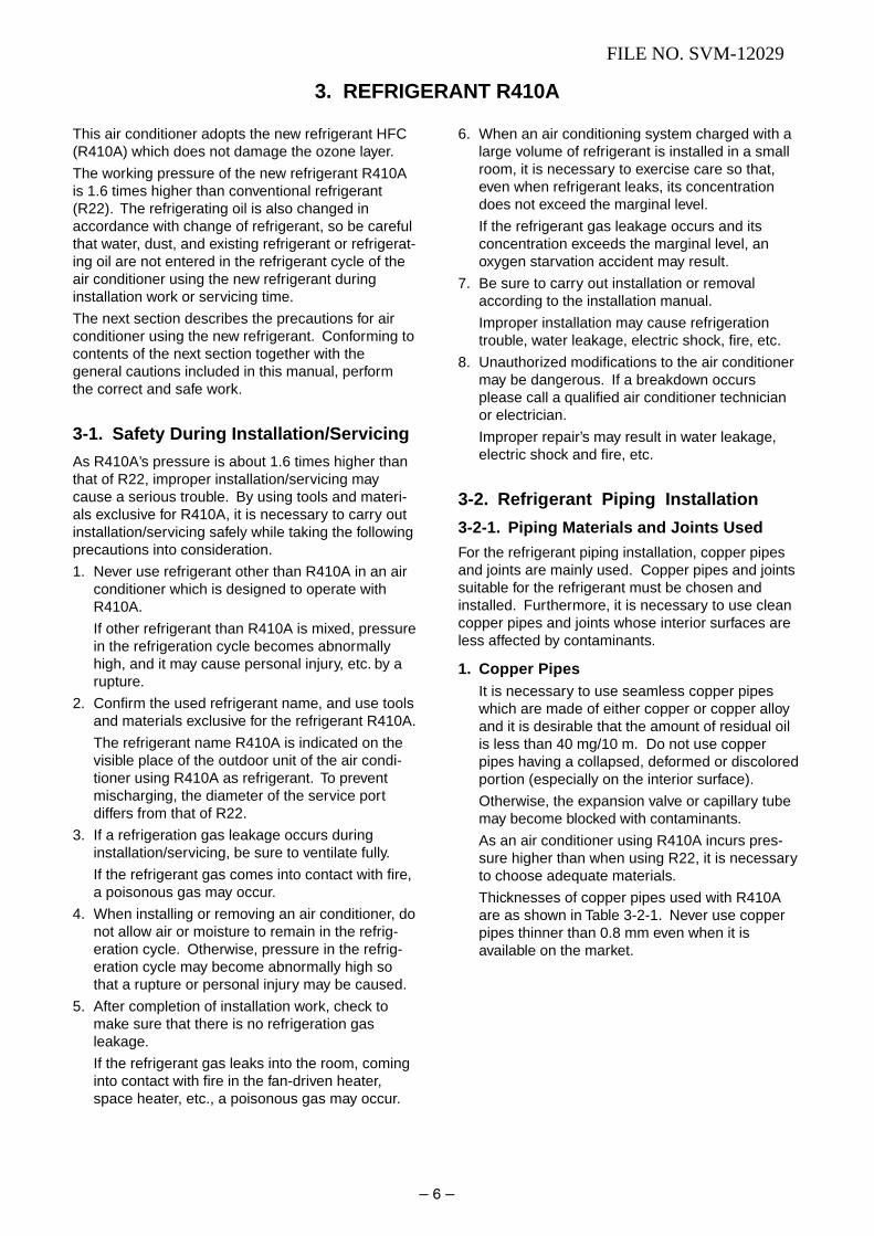
9-3-2. How to Cancel the Au to Restar t Function ................................................................. 40
9-3-3. Power Failure During Timer Operation .................................................................... 40
9-4. Remote Controller and Its Fuctions
9-4-1. Parts Name of Remote Contr oller .............................................................................. 41
9-4-2. Operation of remote control ....................................................................................... 41
13. QUIET mode ............................................................................................................. 37
14. COMFORT SLEEP mode ............ ............................................................................. 37
15. One-Touch Comfort ..................... ............................................................................. 37
16. Hi-POWER Mode ..................... ................................................................................. 38
9-4-3. Name and Functions of Indications on Remote Contr oller ......................................... 44
FILE NO. SVM-12029

– 25 –
Item
1. Basicoperation
Operation flow and applicable data, etc.
1. Operation control
Description
Receiving the user’s operation condition setup, the operation statuses of indoor/outdoor units arecontrolled.
1) The operation conditions are selected by the remote controller as shown in the below.
2) A signal is sent by ON button of the remote controller.
3) The signal is received by a sensor of the indoor unit and processed by the indoor controllers asshown in the below.
4) The indoor controller controls the indoor fan motor and louver motor.
5) The indoor controller sends the operation command to the outdoor controller, and sends/receivesthe control status with a serial signal.
6) The outdoor controller controls the operation as shown in the left, and also controls the compres-sor, outdoor fan motor and 4-way valve.
Remote controller
Indoor unit
Control contents of remote controller• ON/OFF (Air conditioner)• Operation select (COOL/HEAT/AUTO/DRY)• Temperature setup• Air direction• Swing• Air volume select (AUTO/LOW/LOW+/MED/MED+/HIGH)• ECO• ON timer setup• OFF timer setup• Hi POWER
Indoor unit control• Command signal generating function of indoor unit operation• Calculation function (temperature calculation)• Activation compensation function of indoor fan• Cold draft preventive function• Timer function• Indoor heat exchanger release control
• Indoor fan motor• Louver motor
Outdoor unit
Outdoor unit control• Frequency control of inverter output• Waveform composite function• Calculation function (Temperature calculation)• AD conversion function• Quick heating function• Delay function of compressor reactivation• Current release function• GTr over-current preventive function• Defrost operation function
• Compressor• Outdoor fan motor• 4-way valve
Signal receiving
Indoor unit control
Operation command
Serial signal send/receive
Selection ofoperation conditions
ON/OFF
Serial signal send/receive
Outdoor unit control
Inverter
~
• COMFORT SLEEP• QUIET• PRESET• ONE-TOUCH
FILE NO. SVM-120299-2. Operation Description

− 26 −
Operation ON Setup of remote controller
Indoor fan motor control / Louver control / Operation Hz
Control (Requierment)Indoor unit control
Sending of operation command signal
Outdoor unit control [ ]
Compressor revolution control / Outdoor fan motor control /
4-way valve control In cooling operation: ON In heating operation: OFF
Item
1. Basicoperation
Operation flow and applicable data, etc.
2. Cooling/Heating operation
Description
The operations are performed in the following parts by controls according to cooling/heating conditions.
1) Receiving the operation ON signal of the remote controller, the cooling or heating operation signalstarts being transferred form the indoor controller to the outdoor unit.
2) At the indoor unit side, the indoor fan is operated according to the contents of “2. Indoor fanmotor control ” and the louver according to the contents of “9. Louver control ”, respectively.
3) The outdoor unit controls the outdoor fan motor, compressor and 4-way valve according to theoperation signal sent from the indoor unit.
3. AUTO operationSelection of operation modeAs shown in the following figure, the operation starts byselecting automatically the status of room temperature(Ta) when starting AUTO operation.
*1. When reselecting the operation mode, the fanspeed is controlled by the previous operation mode.
4. DRY operationDRY operation is performed according to the differencebetween room temperature and the setup temperature asshown below.
In DRY operation, fan speed is controlled in order toprevent lowering of the room temperature and to avoid airflow from blowing directly to persons.
1) Detects the room temperature (Ta) whenthe DRY operation started.
2) Starts operation under conditions in theleft figure according to the temperaturedifference between the room tempera-ture and the setup temperature (Tsc).Setup temperature (Tsc)= Set temperature on remote controller (Ts) + (0.0 to 1.0)
3) When the room temperature is lower1°C or less than the setup temperature,turn off the compressor.
1) Detects the room temperature (Ta) whenthe operation started.
2) Selects an operation mode from Ta inthe left figure.
3) Fan operation continues until anoperation mode is selected.
4) When AUTO operation has startedwithin 2 hours after heating operationstopped and if the room temperature is20°C or more, the fan operation isperformed with ”Super Ultra LOW” modefor 3 minutes.Then, select an operation mode.
5) If the status of compressor-OFFcontinues for 15 minutes the roomtemperature after selecting an operationmode (COOL/HEAT), reselect anoperation mode.
Ts + 1
Ts – 1
TaCooling operation
Monitoring (Fan)
Heating operation
Tsc
+0.5
+1.0
[˚C]Ta
Fan speed
L– (W5)
(W5+W3) / 2
SUL (W3)
Operation Hz control (Include limit control)
FILE NO. SVM-12029

– 27 –
Item
2. Indoor fanmotor control
Operation flow and applicable data, etc.
<In cooling operation>(This operation controls the fan speed at indoor unit side.)
The indoor fan (cross flow fan) is operated by the phase-control induction motor. The fan rotates in 5 stages inMANUAL mode, and in 5 stages in AUTO mode, respec-tively. (Table 1)
Description
* SymbolsUH : Ultra HighH : HighM+ : Medium+M : MediumL+ : Low+L : LowL- : Low–UL : Ultra LowSUL : Super Ultra Low
* The fan speed broadly varies dueto position of the louver, etc.The described value indicates oneunder condition of incliningdownward blowing.
1) When setting the fan speed to L,L+, M, M+ or H on the remotecontroller, the operation isperformed with the constantspeed shown in Fig. 1.
2) When setting the fan speed toAUTO on the remote controller,revolution of the fan motor iscontrolled to the fan speed levelshown in Fig. 2 and Table 1according to the setup tempera-ture, room temperature, and heatexchanger temperature.
(Fig. 1)
(Fig. 2)
+2.5
Ta[˚C]
+2.0
+1.5
+1.0
+0.5
Tsc
a
b
c
d
e
M+(WB)
*3
*4
*5
L(W6)
Air volume AUTO
L
L+
M
M+
H
W6
(L + M) / 2
W9
(M + H) / 2
WC
Indication Fan speed
Fan speed setup
COOL ON
AUTO
MANUAL
*3 : Fan speed = (M + −L) x 3/4 + L
*4 : Fan speed = (M + −L) x 2/4 + L
*5 : Fan speed = (M + −L) x 1/4 + L
(Linear approximation from M+ and L)
Fan speed
level COOL HEAT DRY Fan speed Air flow rate
(rpm) (m3/h)
WF UH 1350 607
WE H 1300 576
WD UH M+ UH 1250 554
WC H H 1200 522
WB M+ M M+ 1120 486
WA M 1100 468
W9 M L+ 1040 444
W8 L 960 402
W7 L+ L- L+ 910 376
W6 L L 880 360
W5 L- UL L- 830 334
W4 UL UL 800 318
W3 SUL SUL 700 266
W2 SUL 650 239
W1 600 213
(Table 1) Indoor fan and air fl ow ra te
FILE NO. SVM-12029

– 28 –
Item
2. Indoor fanmotor control
Operation flow and applicable data, etc.
<In heating operation>
Description
1) When setting the fan speed to L,L+, M, M+ or H on the remotecontroller, the operation is per-formed with the constant speedshown in Fig. 3 and Table 1.
2) When setting the fan speed toAUTO on the remote controller,revolution of the fan motor iscontrolled to the fan speed levelshown in Fig. 5 according to the settemperature and room temperature.
3) Min air flow rate is controlled bytemperature of the indoor heatexchanger (Tc) as shown in Fig. 4.
4) Cold draft prevention, the fanspeed is controlled by temperatureof the indoor heat exchanger (Tc)as shown in Fig. 6.
[In starting and in stability]
(Fig. 3)
(Fig. 4)
(Fig. 5)
Cold draft preventive control
(Fig. 6)
Fan speedAUTO
Basi c fan contr ol
* No limitation while fan speed MANUAL mode is in stability.* A: When Tsc ≥ 24, A is 24, and when Tsc < 24, A is Tsc
Tsc: Set value
TSC
TA [˚C]b
–0.5c
–1.0d
–1.5e
–2.0f
–2.5g
–5.0
–5.5
L+ (W9)
M+ (WD)
*1
*2
*3
H (WE)
H (WE)
Line-approximateH and SUL with Tc.
SUL (W2)
Stop
46 46Tc
3445 45 33
33 33 2132 32 20
*A+4 *A+4 *A+4
*A-4 *A-4 *A-4
Fan speed MANUAL in startingFan speed AUTO in stabilityFan speed AUTO in starting
L
L+
M
M+
H
W8
(L + M) / 2
WA
(M + H) / 2
WE
Indication Fan speed
Fan speed setup
HEAT ON
AUTO
YES
NO
MANUAL
TC ≥ 42˚C Min air flow rate control
Tc5251
4241
Limited to Min WD tap
* Fan speed =(TC – – W8) + W8
No limit*
*1: Fan speed = (M + -L+) x 1 4 + L+*2: Fan speed = (M + -L+) x 2 4 + L+*3: Fan speed = (M + -L+) x 3 4 + L+(Calculated with linear approximation from M+ and L+)
FAN AUTO
FAN Manual
In starting
• Until 12 minutes passed after operation start• When 12 to 25 minutes passed after operation
start and room temp. is 3°C or lower than set temp.
• Room temp. < Set temp. –4°C
In stability
• When 12 to 25 minutes passed after operation startand room temp. is higher than (set temp. –3°C)
• When 25 minutes or more passed after operation start
• Room temp. ≥ Set temp. –3.5°C
5) In order to prevent cold draft when
compressor stop during heatingoperation. Then louver will move to
upper position and fan speed will
FILE NO. SVM-12029
reduce or off.

– 29 –
Item
3. Capacitycontrol
Operation flow and applicable data, etc.
The cooling or heating capacity depending on the load isadjusted.
According to difference between the setup value of tempera-ture and the room temperature, the capacity is adjusted bythe compressor revolution.
Description
1) The difference between settemperature on remote controller(Ts) and room temperature (Ta)is calculated.
2) According to the temperaturedifference, the correction value ofHz signal which determines thecompressor speed is set up.
3) The rotating position and speedof the motor are detected by theelectromotive force occurred onthe motor winding with operationof the compressor.
4) According to the differenceresulted from comparison of thecorrection value of Hz signal withthe present operation Hz, theinverter output and the commuta-tion timing are varied.
5) Change the compressor motorspeed by outputting power to thecompressor.
* The contents of controloperation are same in coolingoperation and heatingoperation
This function prevents troubles on the electronic parts of thecompressor driving inverter.
This function also controls drive circuit of the compressorspeed so that electric power of the compressor drive circuitdoes not exceed the specified value.
4. Current releasecontrol
Set temp. (Ts) Room temp. (Ta)
Correction of Hz signal
Outdoor temp. To
Setup of current release point
Capacity control continues.
Detection of electromotive forceof compressor motor winding
Detection of motor speed and rotor position
Inverter output changeCommutation timing change
Change of compressor speed
Remote controller Indoor unit
Ts –Ta
Current decrease
Correction value of Hz signal ≤ Operating Hz
Outdoor unit inverter maincircuit control current
High
Low
Reduce compressor speedOperating current ≤Setup value
1) The input current of the outdoorunit is detected in the invertersection of the outdoor unit.
2) According to the detectedoutdoor temperature, thespecified value of the current isselected.
3) Whether the current valueexceeds the specified value ornot is judged.
4) If the current value exceeds thespecified value, this functionreduces the compressor speedand controls speed up to theclosest one commanded from theindoor unit within the rangewhich does not exceed thespecified value.
FILE NO. SVM-12029
Outdoor temp.
45°C
40°C 44°C
16°C 39°C
11°C 15.5°C
10.5°C
Cooling current Heating current
release value release value
3.60A
5.17A
5.17A
7.72A
9.26A
10.80A

– 30 –
Item
5. Release protectivecontrol by tempera-ture of indoor heatexchanger
Operation flow and applicable data, etc.
<In cooling/dry operation>(Prevent-freezing control for indoor heat exchanger)
In cooling/dry operation, the sensor of indoor heatexchanger detects evaporation temperature andcontrols the compressor speed so that temperature ofthe heat exchanger does not exceed the specifiedvalue.
Description
1) When temperature of the indoorheat exchanger drops below 5°C,the compressor speed isreduced. (P zone)
2) When temperature of the indoorheat exchanger rises in therange from 6°C to under 7°C, thecompressor speed is kept.(Q zone)
3) When temperature of the indoorheat exchanger rises to 7°C orhigher, the capacity controloperation returns to the usualcontrol in cooling operation.(R zone)
1) When temperature of the indoorheat exchanger rises in therange from 50°C to 55°C, thecompressor speed is kept.(Q zone)
When temperature of the indoorheat exchanger drops in therange from 46°C to under 55°C,the compressor speed is kept.(Q zone)
2) When temperature of the indoorheat exchanger rises to 55°C orhigher, the compressor speed isreduced. (P zone)
3) When temperature of the indoorheat exchanger does not rise to50°C, or when it drops below to46°C, the capacity controloperation returns to the usualcontrol in heating operation.(R zone)
<In heating operation>(Prevent-overpressure control for refrigerating cycle)
In heating operation, the sensor of indoor heat ex-changer detects condensation temperature and controlsthe compressor speed so that temperature of the heatexchanger does not exceed the specified value.
7˚C
6˚C
5˚C
R
Q
P
55˚C
52˚C
48˚C
P
Q
R
Usual cooling capacity control
Reduction of compressor speedIndo
or h
eat e
xcha
nger
tem
pera
ture
When the value is in Q zone, the compressor speed is kept.
Reduction of compressor speed
Usual heating capacity controlIndo
or h
eat e
xcha
nger
tem
pera
ture
When the value is in Q zone, the compressor speed is kept.
FILE NO. SVM-12029

– 31 –
Item Operation flow and applicable data, etc. Description
6. Defrost control(Only in heatingoperation)
(This function removes frost adhered to the outdoorheat exchanger.)
The temperature sensor of the outdoor heat ex-changer (Te sensor) judges the frosting status of theoutdoor heat exchanger and the defrost operation isperformed with 4-way valve reverse defrost system.
The necessity of defrost operation isdetected by the outdoor heat exchangertemperature. The conditions to detect thenecessity of defrost operation differ in A,B, or C zone each. (Table 1)
<Defrost operation>• Defrost operation in A to C zones
1) Stop operation of the compressor for20 seconds.
2) Invert (OFF) 4-way valve 10 secondsafter stop of the compressor.
3) The outdoor fan stops at the same timewhen the compressor stops.
4) When temperature of the indoor heatexchanger becomes 38°C or lower,stop the indoor fan.
<Finish of defrost operation>• Returning conditions from defrost
operation to heating operation
1) Temperature of outdoor heat exchangerrises to +8°C or higher.
2) Temperature of outdoor heat exchangeris kept at +5°C or higher for 80 seconds.
3) Defrost operation continues for15 minutes.
<Returning from defrost operation>1) Stop operation of the compressor for
approx. 50 seconds.
2) Invert (ON) 4-way valve approx. 40seconds after stop of the compressor.
3) The outdoor fan starts rotating at thesame time when the compressor starts.
Table 1
* The minimum value of Te sensor 10 to 15 minutesafter start of operation is stored in memory as Te0.
–5˚C
0’ 10’ 15’ 27’40” 34’
–7˚C
–20˚C
Operation time (Minute)
Start of heating operation
*
Out
door
hea
t exc
hang
er te
mpe
ratu
re
C zone
A zone
B zone
A zone
B zone
C zone
When Te0 - TE ≥ 2.5 continued for 2 minutes in A zone,defrost operation starts.
When the operation continued for 2 minutes in B zone,defrost operation starts.
When Te0 - TE ≥ 3 continued for 2 minutes in C zone,defrost operation starts.
FILE NO. SVM-12029

Horizontalblowing
Inclinedblowing
Blowingdownward
Air direction
Inclinedblowing
Horizontalblowing
Initial setting of "Cooling storage position"Louver : Directs downward (48°)
Heating operation/AUTO (HEAT)
Initial setting of “Heating storage position”Louver : Directs downward (115.7˚)
Item
7. Louver control
1) Louverposition
Operation flow and applicable data, etc.
This function controls the air direction of the indoor unit.
Description
• Swing operation is performed in width 35° with the stop position asthe center.
• If the stop position exceeds either upper or lower limit position,swing operation is performed in width 35° from the limit which thestop position exceeded.
3) Swing
2) Louver position in heating operation
2) Air direction adjustment
• The position is automatically controlled according to the operation
• The set louver position is stored in memory by the microcomputer,
The angle of the louver is indicated as the louver closes fully is 0°.
1) Louver position in cooling operation
mode (COOL/HEAT).
and the louver returns to the stored position when the next operation
is performed. (Cooling/Heating memory position)
• SwingWhen pressing[SWING] button duringoperation, the louverstarts swinging.
• The louver position canbe arbitrarily set up bypressing [FIX] button.
– 32 –
FILE NO. SVM-12029

– 33 –
Item
8. ECOoperation
Operation flow and applicable data, etc.
When pressing [ECO] button on the remote controller, a Economic operation is performed.
<Cooling operation>
This function operates the air conditioner with the differencebetween the set and the room temperature as shown in thefollowing figure.
Description
<Heating operation> <Heating operation>
1) Setting the compressor speed toMax. aHz, the temperature zonein which the operation can be
performed with Max. cHz isgradually widened after 30minutes passed when startingECO operation.
* 12 (DRY max - COOL min) /6 x 5 + COOL min* 11 (DRY max - COOL min) /6 x 4 + COOL min* 10 (DRY max - COOL min) /6 x 3 + COOL min
* 9 (DRY max - COOL min) /6 x 2 + COOL min* 8 (DRY max - COOL min) /6 x 1 + COOL min
30 minutes
A
B
C
A
B
C
→ Time Compressorspeed 0Hz
A zoneaHz
B zonea to cHz
C zonecHz
0–0.5–1.0–1.5–2.0–2.5–3.0–4.0–5.0–6.0–7.0–8.0–9.0
–10.0–11.0
(Roo
m te
mp.
– S
et te
mp.
)
+3.5
+3.0
+2.5
+1.5
+1.0
TSC
-1.0
-2.0
+5.5
1H 2H
11
10
7
6
5
4
3
2
1
OFF
Dry Max
*12
*11
*9
*8
*10
TA
+6.0
+6.5
3H 4H
+5.0
+4.5
+4.0
+2.0
+0.5
-0.5
12
9
8
Time
Zone Frequency
FAN
MinHz
Fa
n s
pe
ed
de
pe
nd
on
pre
se
ttin
g a
nd
ca
n c
ha
ng
e e
ve
ry s
pe
ed
.
1) The control target temperatureincrease 0.5ºC per hour up to 2ºCstarting from the set temperature
when ECONO has been received.
2) The indoor fan speed is dependon presetting and can change every speed after setting ECO
operation.
<Cooling operation>
2) The indoor fan speed is dependon presetting and can change every speed after setting ECO
operation.
FILE NO. SVM-12029
3) The compressor speed is controlled as shown in the leftfigure.
Hz
Cool min
DRY max
22
32
Hz
a
b
22
52

– 34 –
Item
9. Temporaryoperation
Operation flow and applicable data, etc.
Pressing [RESET] button starts the temporary opera-tion of [AUTO] operation. When keeping [RESET]button pressed for 10 seconds or more, the temporary[COOL] operation is performed.
Description
1) When pressing [RESET] button, thetemporary [AUTO] operation starts.
2) When keeping [RESET] button pressedfor 3 seconds or more, Pi, Pi, Pi sound isheard and [AUTO RESTART] control ischanged.
3) When keeping [RESET] button pressedfor 10 seconds or more, “Pi” sound isheard and the temporary [COOL]operation starts.
4) If the filter lamp goes on, press [RESET]button to go off the filter lamp, and thenpress [RESET] button again.
5) To stop the temporary operation, pressthe button again.
Filter lamp ON Press RESET button.
Did you press [RESET] buttonfor 3 seconds or more?
Did you press [RESET] buttonfor 10 seconds or more?
Switch to [AUTO RESTART] control.
YES
YES
NO
NO
NO
YES
Temporary [AUTO] operation
Temporary [COOL] Operation
10. Discharge temperature control 1. PurposeThis function detects error on therefrigerating cycle or error on the com-pressor, and performs protective control.
2. Operation• Control of the compressor speed
The speed control is performed asdescribed in the left table based uponthe discharge temperature.
Td value
117°C
112°C
108°C
105°C
98°C
Control operation
Judges as an error and stops the compressor.
Reduce the compressor speed.
Reduce slowly compressor speed.
Keeps the compressor speed.
If the operation is performed with lower speed than onecommanded by the serial signal, speed is slowly raisedup to the commanded speed.
Operates with speed commanded by the serial signal.
FILE NO. SVM-12029

– 35 –
Item
11. Self-Cleaning
Operation flow and applicable data, etc.
1. Purpose
The Self-Cleaning operation is to minimize thegrowth of mold, bacteria etc. by runningthe fan and drying so as to keep theinside of the air conditioner clean.
Self-Cleaning operation
When the cooling or dry operation shutsdown, the unit automatically starts the Self-Cleaning operation which is then performedfor the specified period based on durationof the operation which was performedprior to the shutdown, after which theSelf-Cleaning operation stops. (The Self-Cleaning operation is not performed after a heating operation.)
2. Operation
1) When the stop signal from the remotecontroller or timer-off function is received, only the timer indicator light.
2) The period of the Self-Cleaning operationis determined by the duration of theoperation performed prior to thereception of the stop code.
3) After the Self-Cleaning operation has been performed for the specified period, the unit stops operating.
Unit now performing cooling or dry operation
Press “STOP” button
Only timer indicator lights, and Self Cleaning operation starts
Time set now elapses
Operation stops
function
• During Self-Cleaning operations: The louver opensslightly. The indoor fan operates continuously ata speed of 500 rpm.
Cooling: Auto (cooling) Dry
Heating: Auto (heating)
Auto (fan only)
Shutdown
Operation time
Up to 10 minutesNo Self-Cleaning operationperformed (0 minutes)
10 minutes 30 mins.or longer
No Self-Cleaning operation performed
• To stop an ongoing Self-Cleaning operation at any timePress the start/stop button on the remote controller twice during the Self-Cleaningoperation. (After pressing the button for the first time, press it for the
Self-Cleaning operation times
second time without delay (within 10 minutes).)
Description
Self-Cleaning operation time
FILE NO. SVM-12029

Item
11. Self-Cleaningfunction
Operation flow and applicable data, etc.
• Self-Cleaning diagram
Description
Operation display ON OFF OFF
FCU fan ON ON
OFFrpm is depend on presetting. (500RPM)
FCU louver OPEN OPEN (11.3º) CLOSE
Timer displayON or OFF
ONON or OFF
depend on presetting of timer function. depend on presetting of timer function.
CompressorON or OFF
OFF OFFdepend on presetting per room temperature.
CDU fan ON or OFFOFF OFF
depend on presetting per room temperature.
Cool mode or dry mode
operation more than 10 mins.
Self-Cleaning mode
operate 30 mins.
Automatically turn-off.
Operation time
Turn off by remote controller or
timer-off function.
FILE NO. SVM-12029
− 36 −
12. Romote-A or Bselection
1. PurposeThis operation is to operate only oneindoor unit using one remote controller.
2. DescriptionWhen operating one indoor unit in asituation where two indoor units havebeen installed in the same room ornearby rooms, this operation prevents theremote controller signal from beingreceived simultaneously by both units,thus preventing both units from operating.
3. OperationThe indoor unit on which the remotecontroller selection has been set to Breceives the signal of the remote control-ler also set to B.(At the factory the remote controllerselection is set to A on all the indoorunits. There is no A setting display.)
Setting the remote cont rollerTo separate using of remote control for each indoor unit in case of 2 air conditioner are installed nearly.
Remote Control B Setup.1) Press RESET button on the indoor unit to turn
2) Point the remote control at the indoor unit.
3) Push and hold CHK • button on the Remote Control by thetip of the pencil. "00" will be shown
the air conditioner ON.
shown on the display.
4) Press MODE • during pushing CHK • . "B" will
show on the display and "00" will disappear and the air conditioner will turn OFF. The Remote Control B is memorized.
Note : 1. Repeat above step to reset Remote Controlto be A.
2. Remote Control A has mot "A" display.3. Default setting of Remote Control from
factory is A.

Item Operation flow and applicable data, etc. Description
− 37 −
FILE NO. SVM-12029
13. QUIET mode When the [QUIET] button is pressed, the fan of the indoor unit will be restricted the revolving speed at
− until the [QUIET] button is pressed once
Remarks : 1. Quiet mode is unable to work in dry mode. 2. Quiet mode is appropriate to work with less
cooling load and less heating load condition.
Quiet mode is the system which, control the
revolving speed of indoor fan to work
constantly at lower than speed L. In addition,
noise level of indoor unit is less than usual.
speed L
again (cancel Quiet mode).
Because of the fan speed L- may cause notenough the cooling capacity or heating capacity.
The principles of comfort sleep mode are: • Quietness for more comfortable. When
• Save energy by changing room temperature
• The air condition can shut down by itself
Remarks:
1. Comfort sleep mode will not operate in dry
automatically.
mode and fan only mode.
automatically.
room temperature reach setting temperature
Cooling mode
• The preset temperature will increase as
show on ECO operation (Item No. 9)
• Press the [COMFORT SLEEP] button to choose the operating hours. Repeat pressing to select the hours.
• If the [COMFORT SLEEP] button is pressedagain means cancel comfort sleep mode.
Heating mode
• The preset temperature will drop down as
show on ECO operation (Item No. 9)
choose the operating hours. Repeat • Press the [COMFORT SLEEP] button to
pressing to setect thehours.
• If the [COMFORT SLEEP] button is pressedagain means cancel comfort sleep mode.
(1hr, 3hr, 5hr or 9hr)
(1hr, 3hr, 5hr or 9 hr)
15. One-Touch
14. SLEEP mode
Operation condition for model to Europe
market
When an indoor unit receives "One Touch
Comfort Signal" from the remote controller,
the indoor unit operates as following.
1) Air conditioner starts to operation when
the signal is received, even if the air
conditioner was OFF.
2) Operation mode is set according to room
temperature, the same as AUTO mode.
3) Target temperature is 24ºC.
4) Louver position is set as stored position
of the operating mode.
5) Fan is controlled as followings.
One touch comfort is the fully automated operation
that is set according to the preferable condition in
a region.
0 12 25
AUTO *AUTO/L L
FanOperation
Time after operationstarts (min)
*AUTO/L: Fan operates depends on the setting
temperature and room temperature.
During the One Touch Comfort mode if the indoor
unit receives any signal with other operation mode,
the unit will cancel the comfort mode and operates
according to the signal received.
Comfort

Item Operation flow and applicable data, etc. Description
16. Hi-POWER ([Hi-POWER] button on the remote controller
is pressed)
When [Hi-POWER] button is pressed while the indoor
unit is in Auto, Cooling or Heating operation, Hi-
.
Mode
POWER mark is indicated on the display of the remote
controller and the unit operates as follows.
1. Automatic operation
• The indoor unit operates in according to the
current operation.
2. Cooling operation
remote controller does not change.)
The indoor unit's fan speed level increase 1 tap
• The preset temperature drops 1ºC
(The value of the preset temperature on the
3. Heating operation
remote controller does not change.)
The indoor unit's fan speed level increase 1 tap
• The preset temperature increases 2ºC
(The value of the preset temperature on the
4. The Hi-POWER mode can not be set in Dry
operation
− 38 −
FILE NO. SVM-12029

– 39 –
Operation
Press [RESET] button for more thanthree seconds. (Less than 10 seconds)
Motions
The unit is on standby.
↓
The unit starts to operate. The green indicator is on.
↓ After approx. three seconds,
The unit beeps three times The green indicator flashesand continues to operate. for 5 seconds.
If the unit is not required to operate at this time, press [RESET]button once more or use the remote controller to turn it off.
Operation
Press [RESET] button for more thanthree seconds. (Less than 10 seconds)
Motions
The unit is in operation. The green indicator is on.
↓
The unit stops operating. The green indicator is turned off.
↓ After approx. three seconds,
The unit beeps three times. The green indicator flashesfor 5 seconds.
If the unit is required to operate at this time, press [RESET] buttononce more or use the remote controller to turn it on.
9-3. Auto Restart Function
This indoor unit is equipped with an automatic restarting function which allows the unit to restart operating withthe set operating conditions in the event of a power supply being accidentally shut down.The operation will resume without warning three minutes after power is restored.
This function is not set to work when shipped from the factory. Therefore it is necessary to set it to work.
9-3-1. How to Set the Auto Restart Function
To set the auto restart function, proceed as follows:
The power supply to the unit must be on ; the function will not set if the power is off.
Press the [RESET] button located in the center of the front panel continuously for three seconds.
The unit receives the signal and beeps three times.
The unit then restarts operating automatically in the event of power supply being accidentally shut down.
• When the unit is standby (Not operating)
• When the unit is in operation
• While the filter check indicator is on, the RESET button has the function of filter reset betton.
FILE NO. SVM-12029
RESET button
RESET button
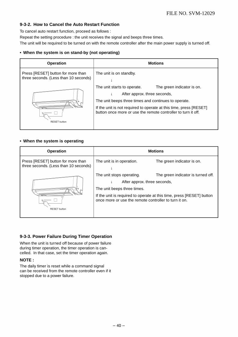
– 40 –
Operation
Press [RESET] button for more thanthree seconds. (Less than 10 seconds)
Motions
The unit is on standby.
↓
The unit starts to operate. The green indicator is on.
↓ After approx. three seconds,
The unit beeps three times and continues to operate.
If the unit is not required to operate at this time, press [RESET]button once more or use the remote controller to turn it off.
Operation
Press [RESET] button for more thanthree seconds. (Less than 10 seconds)
Motions
The unit is in operation. The green indicator is on.
↓
The unit stops operating. The green indicator is turned off.
↓ After approx. three seconds,
The unit beeps three times.
If the unit is required to operate at this time, press [RESET] buttononce more or use the remote controller to turn it on.
9-3-2. How to Cancel the Auto Resta rt Function
To cancel auto restart function, proceed as follows :
Repeat the setting procedure : the unit receives the signal and beeps three times.
The unit will be required to be turned on with the remote controller after the main power supply is turned off.
• When the system is on stand-by (not operating)
• When the system is operating
9-3-3. Power Failure During Timer Operation
When the unit is turned off because of power failureduring timer operation, the timer operation is can-celled. In that case, set the timer operation again.
NOTE :The daily timer is reset while a command signalcan be received from the remote controller even if itstopped due to a power failure.
FILE NO. SVM-12029
RESET button
RESET button

– 41 –
FILE NO. SVM-12029
9-4. Remote Controller and Its Fuctions9-4-1. Parts Name of Remote Controller
Note:
• The provided Remote Controller is a wireless type, which also can be used as a wire.
Please see “How to Connect The Remote Controller for Wired Operation", located in installation instruction,
in case of wired control is required.
• In wire operation, remote controller will return to initial condition (PRESET, TIMER and CLOCK will return
to initial condition) when user shutdown power supply of Air conditioner.
1 Infrared signal emitter
2 Start/Stop button
3 Mode select button (MODE)
4 Temperature button (TEMP)
5 Fan speed button (FAN)
6 Swing louver button (SWING)
7 Set louver button (FIX)
8 On timer button (ON)
9 Off timer button (OFF)
10 Setup button (SET)
11 Clear button (CLR)
12 Memory and Preset button (PRESET)
13 One-Touch button (ONE-TOUCH)
14 High power button (Hi-POWER)
15 Economy button (ECO)
16 Quiet button (QUIET)
17 Comfort sleep button (COMFORT SLEEP)
18 Filter reset button (FILTER)
19 Set clock button (CLOCK)
20 Check button (CHECK)
21 Reset button (RESET)
SWING FAN
FIX QUIET
Hi POWER
ONE-TOUCH
COMFORT
SLEEP
4
5
10
21
11
14
16
8
1
2
13
17
20
15
12
3
19
7
6
18
9
9-4-2. Operation of remote control
1. ONE-TOUCH
Press the "ONE-TOUCH" button for fully automated operation that is customised to the typical consumer
preferences in your region of the world. The coutomised settings control temperature air flow strength, air flow
direction and other settings to provide you alternate contact with "ONE-TOUCH" OF THE BUTTON. If you
prefer other settings you can select from the many other operation functions of your Toshiba unit
Press ONE-TOUCH : Start the operaton.
2. AUTOMATIC OPERATION
To automatically select cooling, heating, or fan only operation.
1. Press MODE : Select A.
2. Press MODE : Set the desired temperature.
3. COOLING / HEATING / FAN ONLY OPERATION
To automatically select cooling, heating, or fan only operation.
1. Press MODE : Select Cool , Heat , or Fan only .
2. Press MODE : Set the desired temperature.
Cooling: Min. 17°C, Heating : Max, 30°C, Fan Only: No temperature indication
3. Press FAN : Select AUTO, LOW , LOW+ , MED , MED+ , or
HIGH .

– 42 –
FILE NO. SVM-12029
4. DRY OPERATION (COOLING ONLY)
For dehumidification, a moderate cooling performance is controlled automatically.
1. Press MODE : Select Dry .
2. Press MODE : Set the desired temperature.
5. Hi-POWER OPERATION
To automatically control room temperature and airflow for faster cooling or heating
Press HI-POWER : Start and stop the operation.
operation (except in DRY and FAN ONLY mode)
6. ECO OPERATION
To automatically control room to save energy (except in DRY and FAN ONLY mode)
Press ECO : Start and stop the operation.
Note: Cooling operation; the set temperature will increase automatically 0.5 degree/
hour for 4 hours (maximum 2 degrees increase). For heating operation the
set temperature will decrease.
7. TEMPORARY OPERATION
In case of the misplaced or discharged remote control
• Pressing the RESET button, the unit can start or stop
without using the remote control.
• Operation mode is set on AUTOMATIC
operation, preset temperature is 24°C
and fan operation is automatic speed.
8. TIMER OPERATION
Setting the ON Timer Setting the OFF Timer
Press ON
: Set the desired ON timer. Press OFF
: Set the desired OFF timer.
Press SET : Set the timer. Press SET : Set the timer.
Press CLR : Cancel the timer. Press CLR
Press
ON
: Set the ON timer. Press
SET
.
Press
OFF
: Set the OFF timer.
Press SET
button during the ( or )
mark flashing.
1
1
2
3
2
3
3
4
Daily timer allows the user to set both the ON & OFF timers and will be activated on a daily basis.
Setting Daily Timer
• During the daily timer is activation, both arrows are indicated.( or )
Note:
• Keep the remote control in accessible transmission to the indoor unit;
otherwise, the time lag of up to 15 minutes will occur.
• The setting will be saved for the next same operation.

– 43 –
FILE NO. SVM-12029
9. PRESET OPERATION
Set your preferred operation for future use. The setting will be memorized by the
unit for future operation (except air flow direction).
1. Select your preferred operation.
2. Press and hold PRESET for 3 seconds to memorize the setting. The mark P
displays.
3. Press PRESET : Operate the preset operation.
10. AUTO RESTART OPERATION
To automatically restart the conditioner after the power failure (Power of the unit
must be on.)
1. Press and hold the RESET button on the indoor unit for 3 seconds to set the
operation. (3 beep sound and OPERATION lamp blink 5 time/sec for 5 secpmds)
• Do not operate ON timer and OFF timer.
2. Press and hold the RESET button on the indoor unit for 3 seconds to cancel the
Setting
operation. (3 beep sound but OPERATION lamp does not blink)
11. QUIET OPERATION
To operate at super low fan speed for quiet operation (except in DRY mode)
Press QUIET : Start and stop the operation.
Note: Under certain conditions, QUIET operation may not provide adequate
cooling or heating due to low sound features.
12. COMFORT SLEEP OPERATION
To save energy while sleeping, automatically control air flow and automatically turn OFF.
Press COMFORT SLEEP : Select 1, 3, 5 or 9 hrs for OFF timer operation.
Note: The cooling operation, the set temperature will increase automatically
0.5 degree/hour for 4 hours (maximum 2 degrees increase). For heating operation,
the set temperature will decrease.

– 44 –
FILE NO. SVM-12029
9-4-3. Name and Funcions of Indications on Remote Controller
All indications, except for the clock time indicator, are displayed by pressing the button.
1. Transmission markThis transmission mark indicates when theremote controller transmits signals to the indoorunit.
2. Mode indicatorIndicates the current operation mode.(A : Auto, : Cool, : Dry, : Heat, : Fan only)
3. Temperature indicatorIndicates the temperature setting.(17°C to 30°C)
5. TIMER and clock time indicatorThe time setting for timer operation or the clocktime is indicated.The current time is always indicated exceptduring TIMER operation.
6. Hi-POWER indicatorIndicates when the Hi-POWER operation starts.Press the Hi-POWER button to start and press itagain to stop the operation.
7. (PRESET) indicatorFlashes for 3 seconds when the PRESET button ispressed during operation.The mark is shown when holding down thebutton for more than 3 seconds while the mark isblinks.
Press another button to turn off the mark.
8. ECO indicatorIndicates when the ECO is in activated.Press the ECO button to start and press it againto stop operation.
9. A, B change indicator remote cont rollerWhen the remote controller switching function isset, “B” appears in the remote controller display.(When the remote controller setting is “A”, there isno indication at this position.)
Indicates when comfort sleep is activaled.Press comfort sleep button to selectter
Indicates when quiet is activated.Press quiet button to start and press it again to stop operation.
Indicates when one touch comfort is activated.Press one-touch button to start the operation.
Indicates when louver is swing.Press swing button to start the swing operationand press it again to stop the swing operation.
10. Comfort sleep
11. Quiet
12. One-Touch
13. Swing
4. FAN speed indicatorIndicates the selected fan speed.
AUTO or five fan speed levels
(LOW , LOW+ , MED , MED+ ,
HIGH ) can be shown.
Indicate Auto will be appear with Dry operation
1 139
734
12
11
2
6
10
58
( : Dry) only.

– 45 –
FILE NO. SVM-12029
10-1-1. Installation Diagram of Indoor and Outdoor Units
Insulate the refrigerant pipes separately
with insulation, not together.
2
38
4
Insert the cushion between the indoor
unit and wall, and tilt the indoor unit for
better operation.
For the rear left and left piping
Wall
Make sure to run the drain hose sloped
downward.
Do not allow the drain hose to get slack.
Cut the piping
hole sloped
slightly.
The auxiliary piping can be connected to
the left, rear left, rear right, right, bottom
right or bottom left.
Right
Rear
right
Bottom
right
Rear
leftBottom left
Left
1
Batteries
Flat head
wood screw Remote control holder
Vinyl tape
Apply after carrying
out a drainage test.
Wireless remote control
Saddle
Extension
drain hose
(Not available,
provided by installer)
Shield pipe(Attach to the front panel.)
Air fi lter
HookInstallation
plate
Hook
47 m
m o
r m
ore
120 mm or more
250 mm or more
60
0 m
m o
r m
ore
100 mm or more
45 mm or more
400 mm or more
600 mm or moreRemark :
• Detail of accessory and installation parts can see in
the accessory sheet.
• Some pictures might be different from the actual parts.
6
5
Filter
Filter
6 mm thick heat resisting
polyethylene foam
10. INSTALLATION PROCEDURE
Before installing the wireless remote controller
• Loading Batteries 1. Remove the battery cover. 2. Insert 2 new batteries (AAA type)
following the (+) and (− ) positions. 3 Batteries
2 Wireless remote controller

– 46 –
FILE NO. SVM-12029
10-1-2. Optional installation parts
<Fixing bolt arrangement of outdoor unit>
Fig. 9-1-2
500 mm
97 mm
53
mm
28
0 m
m
Drain outletAir outlet
Air inlet
∅25 mm
Parts name
Refrigerant piping
Liquid side : ∅6.35 mm
Gas side : 9.52 mm
Pipe insulating material
(polyethylene foam, 6 mm thick)
Putty, PVC tapes
Part
Code
A
B
C
Q'ty
One
each
1
One
each
∅
Secure the outdoor unit with fixing bolts and nuts if the unit is likely to be exposed to a strong wind.
Use ∅ 8 mm or ∅ 10 mm anchor bolts and nuts.
•
•
If it is necessary to drain the defrost water, attach drain nipple 10 and cap water proof 11 to the•
bottom plate of the outdoor unit before installing it.

– 47 –
FILE NO. SVM-12029
10-1-3. Accessory and installation parts
PartNo.
Part name (Q’ty)
Installation plate x 1
Wireless remote control x 1
Battery x 2
Part name (Q’ty)
Remote control holder x 1
Toshiba new IAQ filter x 1
PartNo.
PartNo.
Others Name
Owner’s manual
Installation manual
The part marked with asterisk (*) is packaged with theoutdoor unit.
Part name (Q’ty)
Flat head wood screw
Drain nipple* x 1
Cap water proof x 2
Mounting screw ∅ 4 x 25 s x 6
∅ 3.1 x 16 s x 2
Toshiba new IAQ filter x 1
10
9
8
7
6
5
41
2
3

– 48 –
FILE NO. SVM-12029
• Incidentally, the “refrigerant cylinder” comes with the refrigerant designation (R410A) and protector coating in
the U. S’s ARI specified rose color (ARI color code: PMS 507).
• Also, the “charge port and packing for refrigerant cylinder” require 1/2 UNF 20 threads per inch
corresponding to the charge hose’s port size.
10-1-4. Installation/Servicing Tools
<Changes in the product and components>
In the case of an air conditioner using R410A, in order to prevent any other refrigerant from being charged
accidentally, the service port diameter of the outdoor unit control valve (3 way valve) has been changed.
(1/2 UNF 20 threads per inch)
• In order to increase the pressure resisting strength of the refrigerant piping, flare processing diameter and
size of opposite side of flare nuts has been changed. (for copper pipes with nominal dimensions 1/2 and 5/8)
New tools for R410A
Applicable to R22 model Changes
As pressure is high, it is impossible to measure by
means of conventional gauge. In order to prevent any
other refrigerant from being charged, each port
diameter has been changed.
In order to increase pressure resisting strength, hose
materials and port size have been changed (to 1/2
UNF 20 threads per inch).
When purchasing a charge hose, be sure to confirm
the port size.
As pressure is hight and gasification speed is fast, it
is difficult to read the indicated value by means of
charging cylinder, as air bubbles occur.
The size of opposite sides of flare nuts have been
increased. Incidentally, a common wrench is used for
nominal diameters 1/4 and 3/8.
By increasing the clamp bar’s receiving hole, strength
of spring in the tool has been improved.
Used when flare is made by using conventional flare
tool.
Connected to conventional vacuum pump. It is
necessary to use an adapter to prevent vacuum
pump oil from flowing back to the charge hose.
The charge hose connecting part has two ports-one
for conventional refrigerant (7/16 UNF 20 threads per
inch) and one for R410A. If the vacuum pump oil
(mineral) mixes with R410A a sludge may occur and
damage the equipment.
Exclusive for HFC refrigerant.
New tools for R410A
Gauge manifold
Charge hose
Electronic balance
for refrigerant charging
Torque wrench
(nominal diam. 1/2, 5/8)
Flare tool
(clutch type)
Gauge for projection
adjustment
Vacuum pump adapter
Gas leakage detector
—

– 49 –
FILE NO. SVM-12029
10-2. Indoor Unit
10-2-1. Installation place
• A place which provides the spaces around the
indoor unit as shown in the above diagram.
• A place where there is no obstacle near the air inlet
and outlet.
• A place that allows easy installation of the piping to
the outdoor unit.
• A place which allows the front panel to be opened.
• The indoor unit shall be installed as top of the
indoor unit comes to at least 2 m height.
Also, it must be avoided to put anything on the top
of the indoor unit.
CAUTION
• Direct sunlight to the indoor unit’s wireless
receiver should be avoided.
• The microprocessor in the indoor unit should not
be too close to RF noise sources.
(For details, see the owner’s manual.)
<Remote control>
• A place where there are no obstacles such as a
curtain that may block the signal from the indoor
unit.
• Do not install the remote control in a place exposed
to direct sunlight or close to a heating source, such
as a stove.
• Keep the remote control at least 1 m apart from the
nearest TV set or stereo equipment. (This is
necessary to prevent image disturbances or noise
interference.)
• The location of the remote control should be
determined as shown below.
Fig. 10-2-1
(Top view)
Indoor unit
Receptionrange
Receptionrange
Remotecontrol Remote
control
(Side view)
10-2-2. Cutting a hole and mounting installation
plate
<Cutting a hole>
When installing the refrigerant pipes from the rear.
Fig. 10-2-2
1. After determining the pipe hole position on the
mounting plate (A), drill the pipe hole (∅ 65 mm) at
a slight downward slant to the outdoor side.
NOTE:
• When drilling a wall that contains a metal lath, wire
lath or metal plate, be sure to use a pipe hole brim
ring sold separately.
<Mounting the installation plate>
Fig. 10-2-3
Ind
oo
r u
nit
45° 45°
75°
90 mm
66 mm
65 mm
42 m
m
Pipe hole
35
65
55.5
120
Anchor bolt holes
Hook
Pipe hole
Indoor unit
Thread
Hook
Weight
Pipe hole
7 Mounting screw
Hook1
Installationplate
2 m
or
mo
re f
rom
flo
or

– 50 –
FILE NO. SVM-12029
<When the installation plate is directly mounted on
the wall>
1. Securely fit the installation plate onto the wall by
screwing it in the upper and lower parts to hook up
the indoor unit.
2. To mount the installation plate on a concrete wall
with anchor bolts, utilize the anchor bolt holes as
illustrated in the above figure.
3. Install the installation plate horizontally in the wall.
CAUTION
When installing the installation plate with a
mounting screw, do not use the anchor bolt hole.
Otherwise the unit may fall down and result in
personal injury and property damage.
Fig. 10-2-4
Fig. 10-2-5
Projection15 mm or less
Clip anchor(local parts)
5 mm dia. hole
Anchorbolt
77777 Mountingscrew∅ 4 x 25 sssss
CAUTION
Failure to firmly install the unit may result in
personal injury and property damage if the unit falls.
• In case of block, brick, concrete or similar type
walls, make 5 mm dia. holes in the wall.
• Insert clip anchors for appropriate mounting screws
7.
NOTE:
• Secure four corners and lower parts of the
installation plate with 4 to 6 mounting screws to
install it.
Installation plate<Keep horizontal direction>
10-2-3. Electrical work
1. The supply voltage must be the same as the rated
voltage of the air conditioner.
2. Prepare the power source for exclusive use with the
air conditioner.
NOTE
• Wire type : More than H07RN-F or 60245 IEC66
(1.5 mm2 or more).
CAUTION
• This appliance can be connected to the mains in
either of the following two ways.
(1) Connection to fixed wiring:
A switch or circuit breaker which disconnects
all poles and has a contact separation of at
least 3 mm must be incorporate in the fixed
wiring. An approved circuit breaker or
switches must used.
(2) Connection with power supply plug:
Attach power supply plug with power cord
and plug it into wall outlet. An approved
power supply cord and plug must be used.
NOTE:
• Perform wiring works so as to allow a general
wiring capacity.

– 51 –
FILE NO. SVM-12029
10-2-4. Wiring connection
<How to connect the connecting cable>
Wiring of the connecting cable can be carried out
without removing of the front panel.
1. Remove the air inlet grille.
Open the air inlet grille upward and pull it toward
you.
2. Remove the terminal cover and cord clamp.
3. Insert the connecting cable (according to the local
cords) into the pipe hole on the wall.
4. Take out the connecting cable through the cable
slot on the rear panel so that it protrudes about
15 cm from the front.
5. Insert the connecting cable fully into the terminal
block and secure it tightly with screws.
6. Tightening torque : 1.2 N·m (0.12 kgf·m)
7. Secure the connecting cable with the cord clamp.
8. Fix the terminal cover, rear plate bushing and air
inlet grille on the indoor unit.
CAUTION
• Be sure to refer to the wiring system diagram
labeled inside the front panel.
• Check local electrical cords and also any specific
wiring instructions or limitations.
10-2-5. Piping and drain hose installation
<Piping and Drain Hose Forming>
* Since dewing results in a machine trouble, make
sure to insulate both the connecting pipes. (Use
polyethylene foam as insulating material.)
Fig. 10-2-8
1. Die-cutting Front panel slit
Cut out the slit on the leftward or right side of the front
panel for the left or right connection and the slit on the
bottom left or right side of the front panel for the
bottom left or right connection with a pair of nippers.
2. Changing drain hose
For leftward connection, bottom-leftward connection
and rearleftward connection’s piping, it is necessary to
change the drain hose and drain cap.
<How to remove the Drain Cap>
Clip the drain cap by needle-nose pliers and pull out.
Fig. 10-2-9
Rear right
Rear left
Die
-cu
ttin
g
Fro
nt
pa
ne
l slit
Changin
g
dra
in h
ose
Pip
ing
pre
pa
ratio
n
Bottom left
Left
Bottom right
Right
NOTE :
• Use stranded wire only.
Earth line
Connecting cable
about 15 cm
Stripping length of the connecting cable
10 mm
50 mm
10 mm
110 mm
Terminal cover
Screw
Screw
Cord clampTerminal block
Earth line
Connecting cableScrew
• Wire type : More than H07RN-F or 60245 IEC66
(1.0 mm2 or more).
<How to install the air inlet grille on the indoor unit>
• When attaching the air inlet grille, the contrary of theremoved operation is performed.
Heat insulator
Drain hose
<How to remove the drain hose>
Fig. 10-2-10
• The drain hose can be removed by removing thescrew securing the drain hose and then pulling out
the drain hose.
• When removing the drain hose, be careful of anysharp edges of steel plate. The edges can injuries.
• To install the drain hose, insert the drain hose firmly
until the connection part contacts with heat insulator,
and the secure it with original screw.

– 52 –
FILE NO. SVM-12029
<How to fix the Drain Cap>
1) Insert hexago wrench (4 mm) in a center head.
Fig. 10-2-11
2) Firmly insert drain cap.
Fig. 10-2-12
CAUTION
Firmly insert the drain hose and drain cap;
otherwise, water may leak.
<In case of right or left piping>
• After scribing slits of the front panel with a knife or a
making-off pin, cut them with a pair of nippers or an
equivalent tool.
Fig. 10-2-13
<In case of bottom right or bottom left piping>
• After scribing slits of the front panel with a knife or a
making-off pin, cut them with a pair of nippers or an
equivalent tool.
Fig. 10-2-14
4 mm
Do not apply lubricating oil(refrigerant machine oil) wheninserting the drain cap. Applicationcauses deterioration and drainleakage of the plug.
Insert a hexagonwrench (4 mm)
No gap
Slit
Slit
<Left-hand connection with piping>
Bend the connecting pipe so that it is laid within 43 mm
above the wall surface. If the connecting pipe is laid
exceeding 43 mm above the wall surface, the indoor
unit may unstably be set on the wall. When bending the
connecting pipe, make sure to use a spring bender so
as not to crush the pipe.
Bend the connection pipe within a radius of 30 mm.
To connect the pipe after installation of the unit (figure)
Fig. 10-2-15
NOTE:
If the pipe is bent incorrectly, the indoor unit may
unstably be set on the wall.
After passing the connecting pipe through the pipe
hole, connect the connecting pipe to the auxiliary pipes
and wrap the facing tape around them.
CAUTION
• Bind the auxiliary pipes (two) and connecting
cable with facing tape tightly. In case of leftward
piping and rear-leftward piping, bind the auxiliary
pipes (two) only with facing tape.
Fig.10-2-16
• Carefully arrange pipes so that any pipe does not
stick out of the rear plate of the indoor unit.
• Carefully connect the auxiliary pipes and
connecting pipes to each other and cut off the
insulating tape wound on the connecting pipe to
avoid double-taping at the joint, moreover, seal
the joint with the vinyl tape, etc.
• Since dewing results in a machine trouble, make
sure to insulate both the connecting pipes. (Use
polyethylene foam as insulating material.)
• When bending a pipe, carefully do it not to crush it.
(To the forefront of flare)
Gas side
Outward form of indoor unit
R 30 mm or less (∅ 6.35) R 40 mm or less (∅ 9.52)
(Use polisin (polyethylene core) or the like for
bending pipe.)
Use the handle of screwdriver, etc.
Liquid side
270 mm
170 mm
43 m
m
80
Auxiliary pipes
Indoor unit
Connecting cable
Installation plate

– 53 –
FILE NO. SVM-12029
10-2-6. Indoor unit fixing
1. Pass the pipe through the hole in the wall, and hook
the indoor unit on the installation plate at the upper
hooks.
2. Swing the indoor unit to right and left to confirm that
it is firmly hooked up on the installation plate.
3. While pressing the indoor unit onto the wall, hook it
at the lower part on the installation plate. Pull the
indoor unit toward you to confirm that it is firmly
hooked up on the installation plate.
Fig. 10-2-17
• For detaching the indoor unit from the installation
plate, pull the indoor unit toward you while pushing
its bottom up at the specified parts.
Fig. 10-2-18
Press(unhook)
Hook
1 Installationplate
Hook here
1
2
PushPush
10-2-7. Drainage
1. Run the drain hose sloped downwards.
NOTE
• Hole should be made at a slight downward slant on
the outdoor side.
Fig. 10-2-19
2. Put water in the drain pan and make sure that the
water is drained out of doors.
3. When connecting extension drain hose, insulate the
connecting part of extension drain hose with shield
pipe.
Fig. 10-2-20
CAUTION
Arrange the drain pipe for proper drainage from the
unit.
Improper drainage can result in dew-dropping.
This air conditioner has the structure designed to drain
water collected from dew, which forms on the back of
the indoor unit, to the drain pan.
Therefore, do not store the power cord and other parts
at a height above the drain guide.
Fig. 10-2-21
Inside the roomDrain hose
Shield pipe
Extension drain hose
Wall
Drain guide
Space for pipes
Do not putthe drainhose end inthe drainageditch.
Do not form thedrain hose intoa wavy shape.
Do not putthe drainhose endinto water.
Do not rise thedrain hose.
50 mmor more

– 54 –
FILE NO. SVM-12029
10-3-2. Refrigerant piping connection
<Flaring>
1. Cut the pipe with a pipe cutter.
Fig. 10-3-2
2. Insert a flare nut into the pipe, and flare the pipe.
• Projection margin in flaring : A (Unit : mm)
Fig. 10-3-3
ial (wing nut type)
<Tightening connection>
Align the centers of the connecting pipes and tighten
the flare nut as far as possible with your fingers. Then
tighten the nut with a spanner and torque wrench as
shown in the figure.
Fig. 10-3-4
10-3. Outdoor Unit
10-3-1. Installation place
• A place which provides the spaces around the
outdoor unit as shown in the left diagram.
• A place which can bear the weight of the outdoor
unit and does not allow an increase in noise level
and vibration.
• A place where the operation noise and discharged
air do not disturb users neighbors.
• A place which is not exposed to a strong wind.
• A place free of a leakage of combustible gases.
• A place which does not block a passage.
• When the outdoor unit is to be installed in an
elevated position, be sure to secure its feet.
• An allowable length of the connecting pipe is up
10 m.
• An allowable height level is up to 8 m.
• A place where the drain water does not raise any
problem.
CAUTION
1. Install the outdoor unit without anything blocking
the air discharging.
2. When the outdoor unit is installed in a place
exposed always exposed to strong wind like a
coast or on a high storey of a building, secure
the normal fan operation using a duct or a wind
shield.
3. In particularly windy areas, install the unit such
as to avoid admission of wind.
4. Installation in the following places may result in
trouble.
Do not install the unit in such places.
• A place full of machine oil.
• A saline-place such as the coast.
• A place full of sulfide gas.
• A place where high-frequency waves are likely
to be generated as from audio equipment,
welders, and medical equipment.
Fig. 10-3-1
Strongwind
CAUTION
Do not apply excess torque.
Otherwise, the nut may crack depending on the
conditions.
••
∅ 6.35 0 to 0.5 1.0 to 1.5
∅ 9.52 0 to 0.5 1.0 to 1.5
90° RoughnessObliquity
A
Die Pipe
Warp
Outer dia.R410A
of copper pipe
∅ 6.35 1.5 to 2.0
∅ 9.52 1.5 to 2.0
Flare nutHalf union
Use a wrench to secure. Use a torque wrench to tighten.
Externallythreaded side
Internallythreaded side
Rigid (Clutch type)
Imper
Outer dia. R410A Conventional
of copper pipe tool used tool used

– 55 –
FILE NO. SVM-12029
10-3-3. Evacuating
After the piping has been connected to the indoor unit,you can perform the air purge together at once
85mm
.
AIR PURGEEvacuate the air in the connecting pipes and in theindoor unit using a vacuum pump. Do not use therefrigerant in the outdoor unit. For details, see themanual of the vacuum pump.
<Using a vacuum pump>
Be sure to use a vacuum pump with counter-flowprevention function so that inside oil of the pump doesnot flow backward into pipes of the air conditionerwhen the pump stops. (If oil inside of the vacuum pumpenters into the air conditioner, which use R410A,refrigeration cycle trouble may result.)1. Connect the charge hose from the manifold valve to
the service port of the gas side packed valve.2. Connect the charge hose to the port of the vacuum
pump.3. Open fully the low pressure side handle of the
gauge manifold valve.4. Operate the vacuum pump to start evacuating.
Perform e
Pressure gauge
Manifold valve–101 kPa (− 76 cmHg)
Handle Lo
Connecting pipe
Compound pressure gauge
Vacuumpump
Handle Hi (Keep full closed)
Charge hose (For R410A only)
Vacuum pump adapter forcounter-flow prevention(For R410A only)
Service port (Valve core (Setting pin))
Packed valve at liquid side
Packed valve at gas side
Charge hose (For R410A only)
vacuating f
CAUTION
• KEEP IMPORTANT 5 POINTS FOR PIPING WORK
(1) Take away dust and moisture (Inside of the
connecting pipes.)
(2) Tight connection (between pipes and unit)
(3) Evacuate the air in the connecting pipes using
VACUUM PUMP.
(4) Check gas leak (connected points)
or about 15 minutes if the
(5) Be save to fully open the packed valves
piping length is 20 meters
before operation.
. (15 minutes for20 meters) (assuming a pump capacity of 27 litersper minute. Then confirm that the compoundpressure gauge reading is −101 kPa (− 76 cmHg).
5. Close the low pressure side valve handle of gaugemanifold.
6. Open fully the valve stem of the packed valves(both side of Gas and Liquid).
7. Remove the charging hose from the service port.8. Securely tighten the caps on the packed valves.
Fig.10-3-7
• Tightening torque of flare pipe connections
The operating pressure of R410A is higher than that of
R22. (Approx. 1.6 times).
It is therefore necessary to firmly tighten the flare pipe
connecting sections (which connect the indoor and
outdoor units) up to the specified tightening torque.
Incorrect connections may cause not only a gas
leakage, but also damage to the refrigerant cycle.
Fig. 10-3-5
<Shaping pipes>
1. How to shape the pipes
Shape the pipes along the incused line on the
outdoor unit.
2. How to fit position of the pipes
Put the edges of the pipes to the place with a
distance of 85 mm from the incused line.
Fig. 10-3-6
(Unit : Nám)
Outer dia.Tightening torque
of copper pipe
∅6.35 mm 16 to 18 (1.6 to 1.8 kgf·m)
9.52 mm 30 to 42 (3.0 to 4.2 kgf·m)
Flare atindoor unit side
Flare atoutdoor unit side
Incused line
∅

– 56 –
FILE NO. SVM-12029
<Packed valve handling precautions>
Fig. 10-4-8
• Open the valve stem all the way out, but do not try
to open it beyond the stopper.
Cap Torque
Pipe size of Packed Valve Size of Hexagon wrench
12.70 mm and smallers A = 4 mm
15.88 mm A = 5 mm
• Securely tighten the valve cap with torque in the following table
Cap Size (H)
Valve Rod
Cap
Service
Port Cap
H17 - H19
H22 - H30
H14
H17
14~18 N.m(1.4 to 1.8 kgf·m)
33~42 N.m(3.3 to 4.2 kgf·m)
8~12 N.m(0.8 to 1.2 kgf·m)
14~18 N.m(1.4 to 1.8 kgf·m)
10-4-5. Wiring connection
1. Remove the valve cover from the outdoor unit.
2. Connect the connecting cable to the terminals
as identified with their respective matched numbers
on the terminal block of indoor and outdoor unit.
3. When connecting the connecting cable to the outdoor
unit terminals, make a loop as shown in the installation
diagram of indoor and outdoor unit to prevent water
coming in the outdoor unit.
4. Insulate the unused cords (conductors) from any
A
H
Hexagon wrench
is required.
Service Port Cap
Valve Rod Cap
10
45 40
60 50
10
10
10
L N1 2 3
Connecting cable Power cord
Earth line
Power source
• Wrong wiring connection may cause some electrical parts burn out.
• Be sure to comply with local cords on running the
wire from indoor unit to outdoor unit (size of wire
and wiring method, etc.).
• Every wire must be connected firmly.
• This installation circuit breaker must be used specified
CAUTION
for the power supply line of this air conditioner.
• If incorrect or incomplete wiring is carried out, it willcause an ignition or smoke.
• Prepare the power supply for exclusive use with the
air conditioner.
• This product can be connected to the mains.
Connection to fixed wiring: A switch which
disconnects all poles and has a contact separation
of at least 3 mm must be incorporated in the fixed wiring
Maximum running current
Circuit breaker
50Hz, 220 - 240V Single phase
Power cord
5.0A
6.5A
H07RN-F or 60245 IEC66
CAUTION
Fig. 10-4-9
<Stripping length of the connecting cable>
(1.5 mm
2 or more)
Connecting
cable
Terminal
block
Power
cord
1 2 L N3
water coming in the outdoor unit. Proceed them so
that they do not touch any electrical or metal parts.NOTE : Connecting cable
• Wire type : More than H07RN-F or 60245 IEC66
(1.0 mm2 or more).
60Hz, 220V Single phase

– 57 –
FILE NO. SVM-12029
10-5. Others
• Check the flare nut connections for the gas leak with
a gas leak detector or soap water.
Fig. 10-5-1
10-5-1. Gas leak test
Fig. 10-5-2
10-5-2. Remote Control A-B Selection
• When two indoor units are installed in the same room or
adjacent two rooms, if operating a unit, two units may
receive the remote control signal simultaneously and
operate. In this case, the operation can be preserved
by setting either one remote control to B setting.
(Both are set to A setting in factory shipment.)
• The remote control signal is not received when the
settings of indoor unit and remote control are different.
• There is no relation between A setting/B setting and A
room/B room when connecting the piping and cables.
<Remote control A-B selection>To separate using of remote control for each indoor unit
in case of 2 air conditioners are installed nearly.
<Remote Control B Setup>
1. Press [RESET] button on the indoor unit to turn the air
conditioner ON.
2. Point the remote control at the indoor unit.
3. Push and hold [CHECK] button on the Remote Control
by the tip of the pencil. "00" will be shown on the display
4. Press [MODE] during pushing [CHECK]. "B" will show
on the display and "00" will disappear and the air
conditioner will turn OFF. The Remote Control B
NOTE : 1. Repeat above step to reset Remote
Control to be A.
2. Remote Control A has not "A" display.
3. Default setting of Remote Control from
factory is A.
is memorized [Picture ).
(Picture )1
2
10-5-3. Test operation
To switch the TEST RUN (COOL) mode, press
RESET button for 10 sec.
(The beeper will make a short beep.)
Fig. 10-5-3
10-5-4. Auto resta rt setting
This product is designed so that, after a power failure,
it can restart automatically in the same operating mode
as before the power failure.
InformationThe product was shipped with Auto Restart function
in the off position. Turn it on as required.
<How to set the auto restart>
1. Press and hold the [RESET] button on the indoor unit
3 seconds to set the operation. (3 beep sound and
OPERATION lamp blink 5 time/sec for 5 seconds)
2. Press and hold the [RESET] button on the indoor
unit for 3 seconds to cancel the operation. (3 beep
sound but OPERATION lamp does not blink)
• In case of ON timer or OFF timer are set, AUTO
RESTART OPERATION dose not activate.
Check placesfor outdoor unit
Check places forindoor unit (Flare nutconnection)
1 2
RESET button

– 58 –
FILE NO. SVM-12029
11. HOW TO DIAGNOSE THE TROUBLE
The pulse motor circuits are mounted to both indoor and outdoor units. Therefore, diagnose troubles accordingto the trouble diagnosis procedure as described below. (Refer to the check points in servicing written on thewiring diagrams attached to the indoor/outdoor units.)
Table 11-1
Precautions when handling the new inverter (3DV Inverter)
CAUTION: HIGH VOLTAGEN
The high voltage circuit is incorporated.
Be careful to do the check service, as the electric shock may be caused in case of touching parts on theP.C. board by hand.
The new inverter (3DV inverter) will be incorporated starting with this unit.
(3DV: 3-shunt Discrete Vector control)
The control circuitry has an uninsulated construction.
No.
1
2
3
4
5
Troubleshooting Procedure
First Confirmation
Primary Judgment
Judgment by Flashing LED of Indoor Unit
Self-Diagnosis by Remote Controller
Judgment of Trouble by Every Symptom
No.
6
7
8
9
10
Troubleshooting Procedure
How to Check Simply the Main Parts
Troubleshooting
How to Diagnose Trouble in Outdoor Unit
How to Check Simply the Main Parts
How to Simply Judge Whether OutdoorFan Motor is Good or Bad
IGBT × 6
FET × 6
MCU
Compressor
Fan motorShared potential
Driver
Driver
Amplifier
Amplifier
Fig. 11-1

– 59 –
FILE NO. SVM-12029
CAUTION
A high voltage (equivalent to the supply voltage) is also energized to ground through thesensors, PMV and other low-voltage circuits. The sensor leads and other wires are coveredwith insulated tubes for protection. Nevertheless, care must be taken to ensure that thesewires are not pinched.
Take sufficient care to avoid directly touching any of the circuit parts without first turning offthe power.
At times such as when the circuit board is to be replaced, place the circuit board assembly ina vertical position.Laying the board flat on an electrically conductive object (such as the top panel of the air conditioner'soutdoor unit) while a charge is still retained by the electrolytic capacitors of the inverter's main circuit maycause short-circuiting between the electrolytic capacitors and secondary circuit components and result indamage to the components.
Sensor leads
Do NOT lay the circuit board assembly flat.
Precautions when inspecting the control section of the outdoor unit
NOTE :A large-capacity electrolytic capacitor is used in the outdoor unit controller (inverter). Therefore, if the powersupply is turned off, charge (charging voltage DC280 to 380V) remains and discharging takes a lot of time.After turning off the power source, if touching the charging section before discharging, an electrical shock maybe caused. Discharge the electrolytic capacitor completely by using soldering iron, etc.
< Discharging method >1. Remove the inverter cover (plating) by opening four mounting claws.
2. As shown below, connect the discharge resistance (approx. 100Ω40W) or plug of the soldering iron tovoltage between + – terminals of the C14 (“CAUTION HIGH VOLTAGE” is indicated.) electrolytic capacitor(500µF/400V or 760µF/400V) on P.C. board, and then perform discharging.
Fig. 11-2
Discharging position (Discharging period 10 seconds or more)
Plug of soldering iron
Inverter coverP. C. board (Soldered surface)
Fig. 11-3

– 60 –
FILE NO. SVM-12029
11-1. First Confirmation
11-1-1. Confirmation of Power Supply
Confirm that the power breaker operates (ON) normally.
11-1-2. Confirmation of Power Voltage
Confirm that power voltage is AC 220–230–240 ± 10%.
If power voltage is not in this range, the unit may not operate normally.
11-1-3. Operation Which is not a Trouble (Program Operation)
For controlling the air conditioner, the program operations are built in the microcomputer as described in thefollowing table.
If a claim is made for running operation, check whether or not it meets to the contents in the following table.
When it does, we inform you that it is not trouble of equipment, but it is indispensable for controlling and main-taining of air conditioner.
Table 11-1-1
No.
1
2
3
4
5
6
Operation of air conditioner
When power breaker is turned “ON”, theoperation indicator (Green) of the indoorunit flashes.
Compressor may not operate even if theroom temperature is within range ofcompressor-ON.
In Dry and ECO mode, FAN (air flow)display does not change even though FAN(air flow select) button is operated.
Increasing of compressor motor speedstops approx. 30 seconds after operationstarted, and then compressor motor speedincreases again approx. 30 seconds after.
In AUTO mode, the operation mode ischanged.
In HEAT mode, the compressor motorspeed does not increase up to the maxi-mum speed or decreases before thetemperature arrives at the set temperature.
Description
The OPERATION lamp of the indoor unit flashes whenpower source is turned on. If [ ] button is operated
once, flashing stops.(Flashes also in power failure)
The compressor does not operate while compressorrestart delay timer (3-minutes timer) operates.The same phenomenon is found after power source hasbeen turned on because 3-minutes timer operates.
The air flow indication is fixed to [AUTO].
For smooth operation of the compressor, the compres-sor motor speed is restricted to Max. 41 rps for 2 min-utes, and Max.91 rps for 2 minutes to 3 minutes, respec-tively after the operation has started.
After selecting Cool or Heat mode, select an operationmode again if the compressor keeps stop status for 15minutes.
The compressor motor speed may decrease by high-temp. release control (Release protective operation bytemp.-up of the indoor heat exchanger) or currentrelease control.

– 61 –
FILE NO. SVM-12029
11-2. Primary Judgment
To diagnose the troubles, use the following methods.
1) Judgment by flashing LED of indoor unit
2) Self-diagnosis by service check remote controller
3) Judgment of trouble by every symptom
Firstly use the method 1) for diagnosis. Then, use the method 2) or 3) to diagnose the details of troubles.
11-3. Judgment by Flashing LED of Indoor Unit
While the indoor unit monitors the operation status of the air conditioner, if the protective circuit operates, thecontents of self-diagnosis are displayed with block on the indoor unit indication section.
Table 11-3-1
NOTES :1. The contents of items B and C and a part of item E are displayed when air conditioner operates.
2. When item B and C, and item B and a part of item E occur concurrently, priority is given to the block of item B.
3. The check codes can be confirmed on the remote controller for servicing.
OPERATION (Green)Flashing display (1 Hz)
OPERATION (Green)TIMER (Yellow)FILTER (Orange)Flashing display (5 Hz)
OPERATION (Green)FILTER (Orange)Flashing display (5 Hz)
OPERATION (Green)TIMER (Yellow)Flashing display (5 Hz)
OPERATION (Green)Flashing display (5 Hz) Protective circuit operation for indoor P.C. board
Protective circuit operation for connecting cable and serial signal system
Protective circuit operation for outdoor P.C. board
Protective circuit operation for others(including compressor)
Power failure (when power is ON)Indoor indication
lamp flashes.
Which lamp does flash?
Item
A
B
C
D
E
Checkcode Block display Description for self-diagnosis

FILE NO. SVM-12029
– 62 –
11-4. Self-Di agnosis by Remote Cont roller (Che ck Code)
1. If the lamps are indicated as shown B to E in Table 11-3-1, execute the self-diagnosis by the remote controller.
2. When the remote controller is set to the service mode, the indoor controller diagnoses the operation condi-tion and indicates the information of the self-diagnosis on the display of the remote controller with the checkcodes. If a fault is detected, all lamps on the indoor unit will flash at 5Hz and it will beep for 10 seconds(Beep, Beep, Beep ... ). The timer lamp usually flashes (5Hz) during self-diagnosis.
11-4-1. How to Use Remote Cont roller in Se rvice Mode
Press [CHECK] button with a tip of pencil to set the remote controller to the service mode.
• “ ” is indicated on the display of the remote controller.
Press [ON ] or [OFF ] buttonIf there is no fault with a code, the indoor unit will beep once (Beep) and the display of the remote controller willchange as follows :
• The TIMER indicator of the indoor unit flashes continuously. (5 times per 1 sec.)
• Check the unit with all 52 check codes ( to ) as shown in Table-11-4-1.
• Press [ON ] or [OFF ] button to change the check code backward.
If there is a fault, the indoor unit will beep for 10 seconds (Beep, Beep, Beep...).
Note the check code on the display of the remote controller.
• 2-digits alphanumeric will be indicated on the display.
• All indicators on the indoor unit will flash. (5 times per 1 sec.)
1
2
3
4
Alphanumeric characters are used for the check codes. is 5. is 6. is A. is B. is C. is D.
SWING FAN
FIX QUIET
Hi POWER
ONE-TOUCH
COMFORT
SLEEP
• • •
Fig. 11-4-1
Press [ ] button to release the service mode.
• The display of the remote controller returns to as it
was before service mode was engaged.
Press [CLR] button. After service finish for clear
service code in memory.
• "7F" is indicated on the display of the remote
control.

– 63 –
FILE NO. SVM-12029
Checkcode
Checkcode
Judgment and action
1. Check the room temp. sensor.
2. When the room temp. sensor isnormal, check P.C. board.
1. Check heat exchanger sensor.
2. When heat exchanger sensor isnormal, check P.C. board.
1. Check the motor.
2. When the motor is normal,check P.C. board.
Replace P.C. board.
1. When the outdoor unit neveroperate:
1) Check connecting cable, andcorrect if defective wiring.
2) Check 25A fuse of inverterP.C. board.
3) Check 3.15A of inverter P.C.board.
2. To display [Other] block duringoperation, check compressorthermo. operation and supplygas (check gas leak also).
3. Unit operates normally duringcheck.If return serial signal does notstop between indoor terminal2 and 3, replace inverter P.C.board.If signal stops between indoorterminal 2 and 3, replace indoorP.C. board.
11-4-2. Caution at Servicing
1. After servicing, press the [ ] button to return to the normal mode.
2. After servicing by the check code, turn off breaker of the power supply, and turn on breaker of the powersupply again so that memory in the microcomputer returns the initial status.
However, the check codes are not deleted even if the power supply is turned off because they are stored inthe fixed memory.
3. After servicing, press [CLR] button under check mode status and then send the check code “7F” to theindoor unit. The error code stored in memory is cleared.
Table 11-4-1
Block distinction Operation of diagnosis function
Block
Indoor P.C.board etc.
Notdisplayed
Connectingcable andserial signal
Cause of operation
Short-circuit or discon-nection of the roomtemperature sensor(TA sensor).
Being out of place,disconnection, short-circuit, or migration ofheat exchanger sensor(TC sensor)
Lock of indoor fan ortrouble on the indoor fancircuit
Trouble on other indoorP.C. boards
Return serial signal is notsent to indoor side fromoperation started.
1) Defective wiring ofconnecting cable
2) Operation of compres-sor thermo Gasshortage Gas leak
Airconditioner
status
Operationcontinues.
Operationcontinues.
All off
Operationcontinues.
Operationcontinues.
Remarks
Displayed whenerror is detected.
Displayed whenerror is detected.
Displayed whenerror is detected.
Displayed whenerror is detected.
Flashes whentrouble is detectedon Return serialsignal, and normalstatus when signalis reset.

– 64 –
FILE NO. SVM-12029
Checkcode
Checkcode
Block distinction
Judgment and action
Even if trying operation again, alloperations stop immediately. :Replace P.C. board.
1. Even if connecting lead wire ofcompressor is removed,position-detect circuit erroroccurred. : Replace P.C. board.
2. Measure resistance betweenwires of compressor, andperform short-circuit. : Replacecompressor.
Even if trying operation again, alloperations stop immediately. :Replace P.C. board.
1. Check sensors (TE, TS).2. Check P.C. board.
1. Check discharge temp. sensor(TD).
2. Check P.C. board
Position-detect error, over-currentprotective operation of outdoor fandrive system, fan lock, etc. :Replace P.C. board or fan motor.
1. Check outdoor temp. sensor(TO).
2. Check P.C. board.
When 20 seconds passed afterstart-up, position-detect circuit erroroccurred. : Replace compressor.Trouble on P.M.V.
1. Repeat Start and Stop withinterval of approx. 10 to 40minutes. (Code is not displayedduring operation.)Supply gas.(Check also gas leak).
2. Unit operates normally duringcheck.If return serial signal does notstop between indoor terminalblock 2 and 3, replace inverterP.C. board.If signal stops between indoorterminal block 2 and 3, replaceindoor P.C. board.
1. Trouble on compressor2. Trouble on wiring of compressor
(Missed phase)
1. Check dischage temp. sensor(TD).
2. Gas leakage3. Trouble on P.M.V.
1. Check power voltage.(220–230–240 V +10%)
2. Overload operation of refrigera-tion cycleCheck installation condition(Short-circuit of outdoor diffuser).
1. Check 4-way valve operation.
Block
Outdoor P.C.board
Notdisplayed
Outdoor P.C.board
Others(includingcompressor)
Operation of diagnosis function
Cause of operation
Inverter over-currentprotective circuitoperates. (Short time)
Position-detect circuiterror or short-circuitbetween windings ofcompressor
Current-detect circuiterror
Being out of place,disconnection or short-circuit of the outdoorheat exchanger sensor(TE) or suction temp.sensor (Ts)
Disconnection or short-circuit of dischargetemp. sensor
Outdoor fan drivesystem error
Outdoor heat exchangertemp. sensor error
Compressor drive outputerror, Compressor error(lock, missing, etc.),Break down
Return serial signal hasbeen sent whenoperation started, but itis not sent from halfway.1) Compressor thermo.
operationGas shortageGas leak
2) Instantaneous powerfailure
Compressor does notrotate.(Current protectivecircuit does not operatewhen a specified timepassed after compressorhad been activated.)
Discharge temp.exceeded 117°C
Break down ofcompressor
4-way valve inverse error(TC sensor valuelowered during heatingoperation.)
Airconditioner
status
All off
All off
All off
All off
All off
All off
Operationcontinues
All off
Operationcontinues
All off
All off
All off
Operationcontinues
Remarks
Displayed whenerror is detected.
Displayed whenerror is detected.
Displayed whenerror is detected.
Displayed whenerror is detected.
Displayed whenerror is detected.
Displayed whenerror is detected.
——
Displayed whenerror is detected.
Flashes whentrouble is detectedon return serialsignal, and normalstatus when signalis reset.
Displayed whenerror is detected.
Displayed whenerror is detected.
Displayed whenerror is detected.
——

– 65 –
FILE NO. SVM-12029
11-5. Judgment of Trouble by Every Symptom
11-5-1. Indoor Unit (Including Remote Controller)
(1) Power is not turned on (Does not operate entirely)
<Prima ry check>1. Is the supply voltage normal?
2. Is the normal voltage provided to the outdoor unit?
3. Is the crossover cable connected properly?
4. Is the fuse (F01) blown?
• Be sure to disconnect the motor connector CN31 after shut off the power supply, or it will be a cause ofdamage of the motor.
NO
Turn off power supply once, and 5 second later, turn it on again.
Is OPERATION indicator flashing?
Is it possible to turn on power supply by pushing
[ ] button onremote controller?
Is voltage (DC12V or 5V)
indicated on rear of indoor control board normal?
Does transmission mark on remote controller flash normally,and is its signal
transmitted properly?
Item by symptoms
Operation
Check Item
Considerable principle cause
Measures
Parts (R01, C01, C02, R64, C27, DB01
Remote controller is defective.
Refer to (5) “Troubleshooting for remote controller”.
Parts of a power supply circuit defective.
Unit operates normally.
Replace main P.C. board
Is fuse (F01) of indoor control
board blown?
NO
NO NO
NO YES
YES
YES YES
YES
T01) are defective.
Microcomputeris defective.
(2) Power is not turned on though Indoor P.C. board is replaced
<Confirmation procedure>
YES YES
NO NO
To item of “Power is not turned on”.
Turn on power supply.
Does operation lamp flash?Is wired correctly to white and black
lead wires of terminal board?Correct wiring.

– 66 –
FILE NO. SVM-12029
Turn off power supply once, and turn it on again.
Start to operate indoor unit in cooling operation at airflow level “LOW”.
YES
Change airflow level to “HIGH”.
When rotating thecross-flow fan by handat the operation stop
condition, is the rotation signal(DC+12V 0V) detected between
2 (Purple lead) and 3 (Blue lead) of the motor
connector (CN33) (1 pulse / 1 revolutio).
Dose AC120V orhigher voltage apply to
between red and black leadof the motor?
Is it possible to change airflow level
to “HIGH”?
Stop the operation
Does fan motor continue to operate?
Does indoor fan operate?
Fan motor operates normally.
Replace main P.C. board.
Replace
YES
YES
YES
Motor circuit (D301, IC31, Q30112V power circuit (T01) failure.
Replace the fan motor.
YES
NO
Replace the P.C. board.
NO
NO
NO
Turn OFF the powerChange airflow level to “HIGH”.Change airflow level to “HIGH”.
Is it possible to
YES
rotate cross-flow fan byhand properly?
NO
Turn OFF the power
bearing.
NO
Control P.C. board failure
(3) Only the indoor motor fan does not operate
<Prima ry check>1. Is it possible to detect the power supply voltage (AC220–240V) between and on the terminal block?
2. Does the indoor fan motor operate in cooling operation?(In heating operation, the indoor fan motor does not operate for approximately 10 minutes after it is turnedon, to prevent a cold air from blowing in.)

– 67 –
FILE NO. SVM-12029
(4) Indoor fan motor automatically starts to rotate by turning on power supply
<Inspection procedure>1. Remove the front panel. (Remove 2 screws.)
2. Remove the cover of the fan motor lead wires.
3. Check AC voltage with CN31 connector while the fan motor is rotating.
NOTE :• Using a tester, measure the resistance value of each winding coil.
• Use a thin test rod.
of "Judgment of Trouble by Every Symptom".
AFN-220-20-4D
• Do not disconnect the connector while the fan motor is rotating.
• For P.C. board side, proceed to the item "Only indoor fan does not operate"
1
3
5
123
21
321
3
21
321
3CN31
CN33
P.C. board
WHI
BLK
RED
BLK
REDWHI
BLUPURGRY
BLUPURGRY
Resistance valuePosition (P.C. board)
Between 3 (Black) - 1 (Red)
Between 3 (Black) - 5 (White)
Between 1 (Red) - 5 (White)
249 ± 18 Ω
373.3 ± 20 Ω
623 ± 44 Ω
BLKWHIRED
PURGRY
BLU

– 68 –
FILE NO. SVM-12029
(5) Troubleshooting for remote control
<Primary check>
Check that A or B selected on the main unit is matched with A or B selected on the remote controller.
Push the [ ] button.
Does the transmission
indicator blink?
YES
YES
YESYES
YES
YES
YES
Is there direct
sunlight on the
receptor of the air
conditioner?
Avoid direct
sunlight.
Is there any
thyristor
fluorescent light
nearly?
Keep the air
conditioner away
from thyristor
fluorescent light.
NO
NO
NO NO
NO
NO
NO
NO
Is operation possible
when setting the
temporary switch of the
air conditioner main unit
to “TEST RUN” or
“TEMPORARY AUTO”?
Can any signal tone
be heard in a transistor
radio when transmitting
within 5 cm distance
from the radio?
P.C. board is failure.
Replace
P.C. board
Is operation
possible when the
transmitter is moved
nearer to the infrared
signal receiver of the
air conditioner?
Battery life
Replace the
batteries
Dose the
transmission
indicator light?
Is there any
beep and
operation?
Normal
Remote control
is failure.
Replace remote
control.
Push the [ ]
button
YES
There is no beep from the indoor unit
The OPERATION lamp of the
air conditioner main unit does not light
Press RESET button
on remote control
with tip of pencil

– 69 –
FILE NO. SVM-12029
Refer to the chart in 11-6.
Gas leak
P.M.V. is defective.
Miswiring of connecting wires of indoor/outdoor units
Clogging of pipe and coming-off of TC sensor
Gas circulation amount is down.
Measure gas pressure.
Gas shortage
Gas leak
Pipe clogging
Thermo. operation of compressor
Red
White
Terminal block
S5277G
Tester
3
2
1
Terminal block at indoor side
S5277G or equivalent (G or J type) (Diode with rated voltage of 400V or more is acceptable.)
To item of Outdoor unit does not operate.
11-5-2. Wiring Failure (Interconnecting and Serial Signal Wire)
(1) Outdoor unit does not operate1) Is the voltage between and of the indoor terminal block varied?
Confirm that transmission from indoor unit to outdoor unit is correctly performed based upon the follow-ing diagram.
NOTE:• Measurement should be performed 2 minutes and 30 seconds after starting of the operation.
• Be sure to prepare a diode for judgment.
Normal time : Voltage swings between DC15 and 60V. ................... Inverter Assembly check (11-5-1.)
Abnormal time : Voltage does not vary.
(2) Outdoor unit stops in a little while after operation started
<Check procedure> Select phenomena described below.1) The outdoor unit stops 10 to 20 minutes after operation started, and 10 minutes or more are required to
restart the unit.
2) If the unit stops once, it does not operate until the power will be turned on again.
3) The outdoor unit stops 10 minutes to 1 hour after operation started, and an alarm is displayed.(Discharge temp. error check code 03, 1E Sensor temp. error check code 02, 1C)

– 70 –
FILE NO. SVM-12029
NO
NO
NO
NO
YES
YES
YES
YES
YES
Gas leakage, disconnection of TS/TC sensors (Check code 02, 1C)
Discharge temp. error, gas leakage(Check code 03, 1E)
1C 1E
Gas amount check and valve clogging check
Remove TC sensor connector from the P.C. board in indoor unit.(Remove connector from the P.C. board.)Operate the air conditioner in COOL mode by TEMP button (“Beep” sound is heard if keeping pushed for 10 seconds.).The operation enters temporary operation mode which fixes opening degree of compressor speed. Check condensation at outlet of PMV, and then check operating pressure from the service port.
Valve drive check
Check the operating pressure from service port, and add gas if pressure is low.
Is connecter of coil connected to inverter?
Is coil of the pulse motor valve (P.M.V.) correctly set?
Existence of condensation at outlet of P.M.V.If there is condensation at outlet (1/4 inch=Ø6.35mm valve side),
the valve is clogged.
Are temp. sensors of indoor/outdoor units correctly set to the holder?NOTE :The temperature sensors which are used to control pulse motor valve include indoor heat exchanger sensor (TC), outdoor heat exchanger temp. sensor (TE), outdoor suction temp. sensor (TS) and outdoor sensor (TO).
Set it correctly.
Set it correctly.
Set it correctly.
Replace coil valve.
Replace valve.
Add gas.
Is positioning sound of valve (sound hitting to stopper) heardfrom valve when the air conditioner starts the operation after turning off power
of the air conditioner once?
11-6. How to Check Simple the Main Parts
<Check procedure>

– 71 –
FILE NO. SVM-12029
11-7. How to Di agnose Trouble in Outdoor Unit
11-7-1. Summari zed Inner Di agnosis of I nverter Assem bly
Table 11-7-1
Diagnosis/Process flowchart Item
Preparation
Check
Check
Operation
Measure-ment
Check
Stop
CheckMeasure-
ment
Contents
Turn “OFF” the power supplybreaker, and remove 3Pconnector which connectsinverter and compressor.
• Check whether 25A fuseon the control boardassembly is blown or not.(F01)
Turn on the power breaker,and operate the air condi-tioner in COOL mode by timeshortening.
Measure terminal voltage ofthe electrolytic capacity.
After operation, turn off thepower breaker after 2minutes 20 seconds passed,and discharge the electro-lytic capacitor by solderingiron.Check voltage betweenmotor phases.
• Is not winding between -‚ -, or - openedor short-circuited?
• Is not frame grounded with, , or ?
Summary
If fuse was blown, be sure tocheck the electrolyticcapacitor and diode block.(DB01)
• Connect dischargeresistance (approx. 100Ω,40W) or soldering iron(plug) between +, –terminals of the electro-lytic capacitor (500µF or760µF) of C14 (with printedCAUTION HIGH VOLTAGE)on P.C. board.
OK if 500µF or 760µF →DC280 to 380V
Remove CN300 whilepushing the part indicatedby an arrow because CN300is a connector with lock.
→ Resistance betweenphases should beapprox. 55 to 77Ω
→ Should be 10MΩ ormore.
Replace outdoor fan motor.
Remove connector of compressor.
NG
NG
NG
NO
OK
OK
OK
YES
Check 25A fuse(Part No.F01).
Does outdoor fan rotate?
Replace fuse.
Check electrolytic
capacitor, diodeblock (DB01),
etc.
Check electrolytic
capacitor, diode (DB01),
etc.
Remove connector CN300 of outdoor fan
motor, and using a tester, check resistance
value between every phases at motor side.
Check terminal voltageof electrolytic
capacitor.
BA
Discharging position (Discharging period 10 seconds or more) Plug of
soldering iron
500µF:400WV x 3
760µF:400WV x 3

– 72 –
FILE NO. SVM-12029
Diagnosis/Process flowchart Item
Check
Operation
Contents
Check winding resistancebetween phases of compres-sor, and resistance betweenoutdoor frames by using atester.
• Is not grounded.
• Is not short-circuitedbetween windings.
• Winding is not opened.
Remove connector CN300 ofthe outdoor fan motor, turnon the power supply breaker,and perform the operation.(Stops though activation isprompted.)
Check operation within 2minutes 20 seconds afteractivation stopped.
NG
OK
BA
Replace control board assembly.
Replace control board.
Replace compressor.
Check compressor
winding resistance.
Summary
→ OK if 10MΩ or more
→ OK if 0.51Ω → 0.57Ω(Check by a digital tester.)
11-8. How to Che ck Simp ly the Main Parts
11-8-1. How to Che ck the P.C. Board (Indoor Unit)
(1) Operating precautions1) When removing the front panel or the P.C. board, be sure to shut off the power supply breaker.
2) When removing the P.C. board, hold the edge of the P.C. board and do not apply force to the parts.
3) When connecting or disconnecting the connectors on the P.C. board, hold the whole housing. Do not pullat the lead wire.
(2) Inspection procedures1) When a P.C. board is judged to be defective, check for disconnection, burning, or discoloration of the
copper foil pattern or this P.C. board.
2) The P.C. board consists of the following 2 parts
a. Main P.C. board part :DC power supply circuit, Indoor fan motor control circuit, CPU and peripheral circuits,buzzer, and Driving circuit of louver.
b. Indication unit of infrared ray receiving infrared ray receiving circuit, LED :To check defect of the P.C. board, follow the procedure described below.

– 73 –
FILE NO. SVM-12029
Table 11-8-1
No.
1
2
3
4
5
6
7
Procedure
Turn off the power supply breakerand remove the P.C. boardassembly from electronic partsbase. Remove the connectingcables from the terminal block.
Remove the connector of themotor and turn on the powersupply breaker. If OPERATIONindicator flashes (once persecond), it is not necessary tocheck steps (1 to 3) in the rightnext column.
Push [ ] button onceto start the unit. (Do not set themode to On-Timer operation.)
Shorten the restart delay timerand start unit.
Push [ ] button once to startthe unit.• Shorten the restart delay timer.• Set the operation mode to
COOL.• Set the fan speed level to
AUTO.• Set the preset temperature
much lower than the roomtemperature. (The unit (com-pressor) operates continuouslyin the above condition.)
If the above condition (No. 5) stillcontinues, start the unit in thefollowing condition.• Set the operation mode to
HEAT.• Set the preset temperature
much higher than room tem-perature.
Connect the motor connector tothe motor and turn on the powersupply.Start the unit the followingcondition.• Set the fan speed level to HIGH.
(The unit (compressor) operatescontinuously in the abovecondition in No. 5.)
Check points
Check whether or not the fuse (F01)is blown.
Check power supply voltage :1. Between No. 1 and No. 3 of CN01
(AC 220–240V)2. Between and of C27
(DC 310–340V)3. Between 12V and GND
4. Between 5V and GND
Check power supply voltage :1. Between CN51 and
No. 1 of CN01 (DC 15–60V)
Check whether or not all indicators(OPERATION,TIMER) are lit for 3seconds and they return to normal3 seconds later.
1. Check whether or not thecompressor operates.
2. Check whether or not theOPERATION indicator flashes.
1. Check whether or not thecompressor operates.
2. Check whether or not theOPERATION indicator flashes.
1. Check it is impossible to detectthe voltage (AC120V or highervoltage) between red and black
2. The motor does not operate orthe fan motor does not rotate withhigh speed.(But it is possible to receive the
signal from the remote controller.)3. The motor rotates but vibrates
Causes
Impulse voltage was applied or theindoor fan motor short-circuited.
1. The terminal block or the crossovercable is connected wrongly.
2. The capacitor (C01), line filter(L01), resistor (R64), or the diode(DB01) is defective.
3. T01 is defective.
4. IC02 and T01 are defective.
IC51 and IC52 are defective.
The indicators are defective or thehousing assembly (CN20) is defective.
1. The temperature of the indoor heatexchanger is extremely low.
2. The connection of the heatexchanger sensor is loose.(The connector is disconnected.)(CN62)
3. The heat exchanger sensor and theP.C. board are defective.(Refer to Table 11-4-1.)
4. The main P.C. board is defective.
1. The temperature of the indoor heatexchanger is extremely high.
2. The connection of the heatexchanger sensor short-circuited.(CN62)
3. The heat exchanger sensor and theP.C. board are defective.(Refer to Table 11-4-1.)
4. The main P.C. board is defective
1. The indoor fan motor is defective.(Protected operation of P.C. board.)
2. The P.C. board is defective.3. The connection of the motor
connector is loose.
lead of the motor.
strongly.
(3) Check procedures

– 74 –
FILE NO. SVM-12029
100
30
40
50
60
70
80
90
20
10
00 10 20 30 40 50
Res
ista
nce
valu
e (k
)
Temperature (˚C)
TD : Discharge temp. sensorTA : Room temp. sensorTC : Heat exchanger temp. sensorTO : Outdoor temp. sensorTE : Outdoor heat exchange temp. sensor
TA, TC, TO, TE
TD
[1] Sensor characteristic table
+ 12V GND
+ 5V
+12V
11-8-2. P .C . Board Layout

– 75 –
FILE NO. SVM-12029
1 Room temp. (TA) sensor
Heat exchanger (TC) sensor
2 Remote control
3 Louver motor
MP24ZCT
4 Indoor fan motor
Disconnect the connector and measure the resistance value with tester.
(Normal temp.)
Refer to 11-5-1 (5)
Measure the resistance value of each winding coil by using the tester.
(Under normal temp. 25°C)
Refer to 11-5-1 (3) and (4).
11-8-3. Indoor unit (Other parts)
No. Part name Checking procedure
11-8-4. Outdoor unit
Sensor
TA, TC (kΩ) 20.7 12.6 10.0 7.9 4.5
5
4
3
2
1White
Yellow
Yellow
Yellow
Yellow 5
4
3
2
1Position Resistance value
1 to 2
1 to 3250±20Ω
1 to 4
1 to 5
Temperature10°C 20°C 25°C 30°C 40°C
No.
1
Part name
Compressor(Model : DA89X1C-23EZ)
Checking procedure
Red
White Black
Measure the resistance value of each winding by using the tester.
Position
Red - White
White - Black
Black - Red
Resistance value
Under 20ºC
1.1Ω
2 Outdoor fan motor(Model : WLF-240-20A-1)
3
Measure the resistance value of winding by using the tester.
N
Red
White
C1.5 mF
450V
Black
Position Resistance value
White - Black
Black - Red
260.1
235.2
Outdoor temperature sensor
(TO), discharge temperature
sensor (TD), suction temperatureexchanger temperature sensor
(TE)
Disconnect the connector, and measure resistance value with the tester.
(Normal temperature)
TGa : Heat pump model only.
TO, TS, TE : Refer to the TA, TC characteristic table in Indoor
(Refer to Table 11-8-3, No.1).
Temperature10°C 20°C 30°C 40°C 50°C
Sensor
TA, TC (kΩ) 105 64 41 27 18
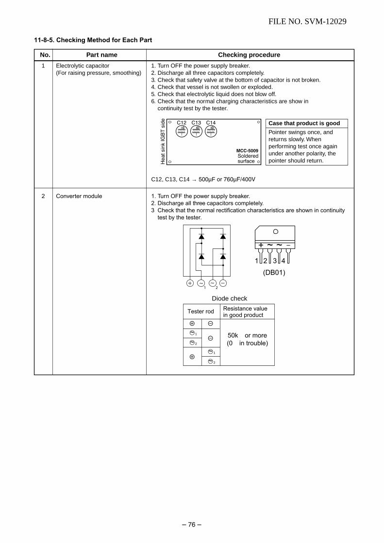
– 76 –
FILE NO. SVM-12029
11-8-5. Checking Method for Each Part
1 Electrolytic capacitor 1. Turn OFF the power supply breaker.(For raising pressure, smoothing) 2. Discharge all three capacitors completely.
3. Check that safety valve at the bottom of capacitor is not broken.4. Check that vessel is not swollen or exploded.5. Check that electrolytic liquid does not blow off.6. Check that the normal charging characteristics are show in
continuity test by the tester.
C12, C13, C14 → 500µF or 760µF/400V
2 Converter module 1. Turn OFF the power supply breaker.
2. Discharge all three capacitors completely.
3 Check that the normal rectification characteristics are shown in continuity
test by the tester.
Case that p roduct is good
Pointer swings once, andreturns slowly. Whenperforming test once againunder another polarity, thepointer should return.
No. Part name Checking procedure
Soldered
surfaceHeatsinkIG
BTside
C12 C13 C14
MCC-5009
1 2
Diode check
e d
d
e
\1~
\2~
\1~
\2~
Tester rod Resistance valuein good product
50k or more
(0 in trouble)
~+ ~
1 2 3
(DB01)
4

– 77 –
FILE NO. SVM-12029
11-9. How to Simp ly Judge Whether Outdoor Fan Motor is Good or Bad
1. Symptom• Outdoor fan motor does not rotate.
• Outdoor fan motor stops within several tens seconds though it started rotating.
• Outdoor fan motor rotates or does not rotate according to the position where the fan stopped, etc.
Remote controller check code “02 : Outdoor block, 1A : Outdoor fan drive system error”
2. CauseThe following causes are considered when the outdoor fan motor does not normally rotate.
1) Mechanical lock of the outdoor fan motor
2) Winding failure of the outdoor fan motor
3) Position-detect circuit failure inside of the outdoor fan motor
4) Motor drive circuit failure of the outdoor P.C. board
3. How to simply judge whether outdoor fan motor is good or bad
NOTE :However, GND circuit error inside of the motor may be accepted in some cases when the above check isperformed.
When the fan motor does not become normal even if P.C. board is replaced, replace the outdoor fan motor.
If the resistance value between 1 (Red lead) – 2 (White lead)2 (White lead) – 3 (Black lead)3 (Black lead) – 1 (Red lead)
of the connector (CN300 : Motor winding) is 17 to 25Ω, it is normal.
Turn OFF the breaker.
Fan motor is normal.
Does the fan rotate without trouble when rotating it with hands?
Disconnect two connectors (CN300) of theoutdoor fan motor from the outdoor P.C. board.
(Outdoor P.C. board error)
Fan motor error
YES
YES
NO
NO
CN300

– 78 –
FILE NO. SVM-12029
12. HOW TO REPLACE THE MAIN PARTS
12-1. Indoor Unit
How to remove the front panel
1) Stop the operation of the air conditioner and
turn off its main power supply.
2) Pull the air inlet grille toward you to open it
and remove the air inlet grille.
Then remove the 2 screws fixing the front
panel.
3) First open the horizontal louver, and then
remove the front panel from the back body
by pulling it toward you.
How to mount the front panel
Push the front panel back in and make sure
all hooks are locked.
How to remove the electrical part.
1) Remove the front panel with procedure 1 .
2) Remove the screw holding the electrical part
cover.
3) Disconnect the 3 connectors 2-(3P) for the fan
motor and the connector (5P) for the louver
motor from the P.C. board assembly.
4) Pull out the TC sensor from the sensor
holder.
5) Remove the screw for the ground connection,
remove the screw for the electrical part box.
Then remove the LED and the electrical part
box from the main unit.
How to mount the electrical part.
1) To put back the electrical part box, lock it to
the upper hook of the back body.
2) Tighten the screws on the electrical part box.
3) Connect the 3 connectors and arrange the
wiring same as original condition and then
tighten the screw from the LED unit to the
back body.
4) Attach the TC sensor to the holder.
5) Tighten the screw for the ground connection.
6) Tighten the screw on the electrical part cover.
1) Remove the front panel and the electrical
part following procedure 2.
2) Remove the center shaft of the horizontal
louver from the back body.
3) Remove the left shaft from the back body.
4) Remove the horizontal louver from the back
body.
No. Part name Procedures Remarks
2 Screws
4 TC Sensor
3
3-Connectors
3
2
22
2 2-Screws
1 Front panel
2 Electrical part
3 Horizontal
louver
5 Screws
3 Left shaft 2 Center shaft

– 79 –
FILE NO. SVM-12029
1) Remove the front panel, electrical part and
the horizontal louver following procedure 3.
2) Remove the pipe holder at the rear side of
main unit.
3) Remove the 2 screws on the heat exchanger
at the base bearing.
4) Remove the screw on the heat exchanger
at the fixed plate from the back body and then
pull out the right hand side until the socket of
heat exchanger released from the hook of the
1) Remove the front panel, electrical part,
horizontal louver and the heat exchanger
following procedure 4.
2) Remove the 2 screws on the band motor (L)
and remove the 2 screws on the band motor
(R) and then remove the cross flow fan.
3) Loosen the set screw of the cross flow fan
then separate the fan and the fan motor.
Notice
To assemble cross flow fan and fan motor to the
unit, please turn the fan motor unit the center of
its terminal meets the top position of band motor
(R).
Fix the cross flow fan with the set screw at the
position where the gap between the back body
and the right surface of the cross flow fan is
4.7 mm.
1) Remove the front panel, electrical part,
horizontal louver, heat exchanger and the
cross flow fan following procedure 5.
2) Remove the 2 screws fixing the base bearing.
3) Remove the bearing from the base bearing. If
the housing protrudes from the base bearing,
put the housing in position and attach the
bearing to the base bearing.
4.7 mm
4 Heat exchanger
5 Cross flow fan
6 Base bearing
Middle of the fan motor terminal
6 Set screw
No. Part name Procedures Remarks
band motor (L), and then pull out the upper
side of heat exchanger slowly.
2 Pipe holder
3
2-Screws
4
2-Screws (R)
2
2-Screws (L)2
2-Screws
2
Screws
– 80 –
FILE NO. SVM-12029
No.
Part name
Common procedure
Procedure
1) Turn the power supply off to stop theoperation of air-conditioner.
2) Remove the front panel.• Remove the 2 fixing screws.
3) Remove the electrical part base.
Remarks
12-2. Microcomputer

– 81 –
FILE NO. SVM-12029
12-3. Outdoor Unit
No. Part name Procedures Remarks
1. Detachment1) Stop operation of the air conditioner, and
turn off the main switch and breaker of theair conditioner.
2) Remove the valve cover. (ST1T∅ 4 x 10s
1 pc)• After removing screw, remove the valve
cover pulling it downward.3) Remove the wiring cover (ST1T∅ 4 x 10s 2
pcs.), and then remove the power cord,connecting cable, and cord clamp(ST2T∅ 4 x 16s 3 pcs.).
4) Remove the upper cabinet.(ST1T∅ 4 x 10s 5 pcs.)• After removing screws, remove the
upper cabinet pulling it upward.
2. Attachment1) Attach the upper cabinet.
(ST1T∅ 4 x 10s 5 pcs.)• Hook the rear side of the upper cabinet
to the claw of the rear cabinet, and thenplace it on the front cabinet.
2) After connecting the power cord andconnecting cable, attach the cord clampand wiring cover.• Insert the upper part into the upper
cabinet, and insert the claw which hasbeen hooked to the lower part into thesquare hole, and then fix it with screw.(ST1T∅ 4 x 10s 1 pc.)
3) Attach the valve cover. (ST1T∅ 4 x 10s 1 pc.)• Insert the upper part to the upper
cabinet, set the hook claw of the valvecover to square holes (at threepositions) of the main unit, and attach itpushing upward.
1. Detachment1) Perform work of item 1 of 1.2) Remove upper screw (ST1T∅ 4 x 10s 4 pcs.)
of the front cabinet, and lower screws(ST1T∅ 4 x 10s 8 pcs.) of the front cabinet.• Both side of front cabinet envelop the
unit, so remove it by pulling sideward.
2. Attachment1) Assemble front cabinet to the unit.
2) Attach the removed screws to the original
positions.
1 Commonprocedure
2 Front cabinet
Upper cabinet
Wiring cover
Valve cover
Upper cabinet

– 82 –
FILE NO. SVM-12029
No. Part name Procedures Remarks
1) Perform work of item 1 of 1.2) Remove screw (ST1T∅ 4 x 10s 1 pc.) of
the upper part of the front cabinet.• If removing the inverter cover in this
condition, the P.C. board can be checked.• If there is no space in the upper part of
the upper cabinet, perform work of 2.
Be careful when checking theinverter because high-voltagecircuit is incorporated in it.
3) Perform discharging by connecting thee,d polarities by discharging resistance(approx. 100Ω40W) or plug of solderingiron to e,d terminals of the C13 (printed“CAUTION HIGH VOLTAGE” is attached.)electrolytic capacitor (760 µF/400 WV) onthe P.C. board.
Be careful to discharge the capacitorbecause the electrolytic capacitorcannot naturally discharge andvoltage remains depending on themalfunction state in some cases.
NOTE :This capacitor has mass capacity.Therefore, it is dangerous that alarge spark generates if short-circuiting between the e,d polaritieswith screwdriver, etc. for discharging.
4) Perform the work of 2.5) Remove the screw (ST1T∅ 4 x 10s 1 pc.)
fixing the main body and the inverter box.6) Remove the lead wire from the holder on
the terminal block.7) Disconnect the connectors of various lead
wires.
Requirement :As each connector has a lockmechanism, avoid removing theconnector by holding the lead wire,but by holding the connector.
3 Inverterassembly
The connector is one with lock,so remove it while pushing thepart indicated by an arrow.
Be sure to remove the connectorby holding the connector, not bypulling the lead wire.
PC board(Soldered surface)
Inverter cover
Discharging time (Discharging period 10 seconds or more)
Plug of soldering iron
Partition
Terminal block

– 83 –
FILE NO. SVM-12029
No. Part name Procedures Remarks
1) Disconnect lead wires and connectorsconnected from the control boardassembly to other parts.1. Lead wires
• Connection with terminal block :3 wires (Black, White, Orange)
• Connection with compressor : removethe connector (3P)
• Connection with reactor : remove theconnector (2P)
2. Connectors (6 positions)CN300, CN703 : Outdoor fan (3P: white)*
(See Note 1)CN701 : 4 way valve (3P: Yellow)*CN601 : TD sensor (2P: White)CN602 : TO sensor (2P: White)CN500 : Case thermo (2P: White)∗ Note 1) As the connector has a
stopper, release the housinglock when removing.
∗∗ Note 2) Hold the housing (resin part)with stopper and pull out toremove.
2) Remove the control board assembly from
the inver ter box.
Note 2) Remove the claw of the
board support fixed to the
inverter board, and remove
upwards holding the heat
sink.
3) Remove the three screws fixing the heat
sink and control board assemble.
4) Attach the new contro board assembly.
Note 4) When attaching the new
control board assembly.
insert the P.C. board into
the guide rail groove
correctly.
4 Control boardassembly
CN300 CN701
CN602 CN601
CN500
As CN300 and CN701 areconnectors with lock, removewhile pushing the part indicatedby an arrow

– 84 –
FILE NO. SVM-12029
No. Part name Procedures Remarks
1) Perform work of item 1 of 1 and 1 of 2.2) Remove the flange nut fixing the fan motor
and the propeller fan.• Flange nut is loosened by turning
clockwise.(To tighten the flange nut, turn counter-clockwise.)
3) Remove the propeller fan.4) Disconnect the connector for the fan motor
from the inverter.5) Remove the fixing screws (4 pcs.) holding
the fan motor by hand so that it does notfall.
6) Cut the motor lead at the point which is100 mm apart from the connector towardthe fan.
7) Use the connector used for the inverter,and pinch the lead wires using the closedend splice.
1) Perform work of item 1 of 1, 1 of 2
2) Extract refrigerant gas.3) Remove the partition board.
(ST1T∅ 4 x 10s 3 pcs.)4) Remove the sound-insulation material.5) Remove the terminal cover of the
compressor, and disconnect the lead wireof the compressor thermo and thecompressor from the terminal.
6) Remove the pipe connected to thecompressor with a burner.• Make sure the flame does not touch the
4 way valve.7) Remove the fixing screw of the base plate
and heat exchanger.(ST1T∅ 4 x 10s 2 pcs.)
8) Pull upward the refrigeration cycle.9) Remove the nut fixing the compressor to
the base plate.
1) Perform work of item 1 of 1, 1 of 2,and 3.
2) Remove the screw fixing the reactor.(ST1T∅ 4 x 10 2 PCS.)
Fan motor
Compressor
n
oand
p Reactor
Compressor
Reactor
100
Fan motorPropeller fan
Flange nut
Closed end splice
s
.

– 85 –
FILE NO. SVM-12029
No. Part name Procedures Remarks
1. Detachment1) Perform work of item 1 of 1 and 1 of 2.
Requirement:Perform the work on a corrugatedcardboard, cloth, etc. to preventscratches to the product.
2) Remove the front cabinet, and place itdown so that the fan guard side facesdownwards.
3) Remove the hooking claws by pushing aminus screwdriver according to the arrowmark in the right figure, and remove thefan guard.
2. Attachment1) Insert the claws of the fan guard in the
hole of the front cabinet. Push the hookingclaws (8 positions) by your hand and fixthe claws.
Requirement:This completes all the attachingwork. Check that all the hookingclaws are fixed to the specifiedpositions.
q Fan guard
Minus screwdriver
Hooking claw

– 86 –
FILE NO. SVM-12029
1) Cut the sensor 100 mm longer than old one.2) Cut the protective tube after pulling out it
(200 mm).3) Move the protective tube toward the thermal
sensor side and tear the tip of lead wire in two,then strip the covering part.
4) Pass the stripped part through the thermalconstringent tube.
5) Cut the old sensor 100 mm length on theconnector side, and recycle that connector.
6) Tear the lead wire in two on the connector sideand strip and covering part.
7) Twist the leads on the connector and sensorsides, and solder them.
8) Move the thermal constringent tubes towardthe soldered parts and heat them with thedryer and constring them.
9) Wind the attached color tape round the bothterminals of the protective tube when coloredprotective tube is used.
10) Fix the sensor again.
NOTES:1) Store the joint part of the sensor and the
connector in the electric parts box.2) Never joint them near the thermal sensor part.
Otherwise, it would cause insulation inferioritybecause of dew drops.
3) When replacing the sensor using the coloredprotective tube, wind the color tape matchingthe color of that tube.
Replacement oftemperaturesensor forservicing only
Common serviceparts of sensorTO, TD
These are parts forservicing sensors.
Please check thatthe accessoriesshown in the righttable are packed.
Part name Q’ty Remarks
1 Sensor 1 Length: 3 m
2 Sensor Spring (A) 1 For spare
3 Sensor Spring (B) 1 For spare
4 Thermal constringent tube 3 Including one spare
5 Color tape 1 9 colors
6 Terminal 3
No. Part name Procedures Remarks
Cutting here
Cutting here
Thermal constringent tube
Soldered part
Dryer
Winding the color tape
200
100
15
70
Thermal sensor part Connector
Cutting here100
15
70
9

– 87 –
FILE NO. SVM-12029
13. EXPLODED VIEWS AND PARTS LIST
13-1. Indoor Unit (E-Parts Assy)
Location Part Location Part
No. No. No. No.
401 43T60365 TERMINAL BLOCK; 3P 405 43T69612 DISPLAY UNIT
403 43T69319 TEMPERATURE SENSOR 410 43T62003 CORD CLAMP
404 43T69320 TEMPERATURE SENSOR 411 43T69824 PC BOARD
Description Description

– 88 –
FILE NO. SVM-12029
13-2. Indoor Unit
Location Part Location Part
No. No. No. No.
201 43T00581 FRONT PANEL ASSY 217 43T22312 BEARING ASSY, MOLD
202 43T09476 GRILLE OF AIR INLET 218 43T39323 BEARING BASE
203 43T03357 BACK BODY ASSY 219 43T20323 ASSY CROSS FLOW FAN
204 43T80326 AIR-FILTER 220 43T39324 MOTOR BAND (LEFT)
205 43T09392 HORIZONTAL LOUVER 221 43T39321 MOTOR BAND(RIGHT)
206 43T70313 HOSE, DRAIN 222 43T21409 FAN MOTOR
207 43T79301 CAP-DRAIN 224 43T82309 INSTALLATION PLATE
208 43T21402 MOTOR; STEPPING 225 43T66315 WIRELESS REMOTE CONTROLLER
209 43T44387 REFRIGERATION CYCLE ASSY 226 43T83305 HOLDER, REMOTE CONTROL
210 43T47353 PIPE; SUCTION 227 43T62326 TERMINAL COVER
211 43T47355 PIPE; SUCTION 228 43T60317 CORD MOTOR LOUVER
212 43T11319 PIPE SHIELD 229 43T07311 PIPE HOLDER
213 43T19333 HOLDER, SENSOR
Description Description

– 89 –
FILE NO. SVM-12029
13-3. Outdoor Unit
Location Part Location Part
No. No. No. No.
1 43T19335 FAN GUARD 15 43T49327 CUSHION,RUBBER
2 43T20327 PROPELLER FAN 18 43T41423 COMPRESSOR
3 43T00482 FRONT CABINET 19 43T19337 PACKED VALVE COVER
4 43T43403 CONDENSOR ASSEMBLY 20 43T00481 UPPER CABINET
5 43T62323 TERMINAL COVER 21 43T00448 FIXING PLATE VALVE
6 43T19341 FIN GUARD 22 43T42331 BASE PLATE ASSEMBLY
7 43T47308 CAPILLARY TUBE; 1.0 DIA 23 43T79305 DRAIN NIPPLE
8 43T46366 VALVE;PACKED 9.52 DIA 24 43T46351 REACTOR
9 43T47332 BONNET, 9.52 DIA 25 43T46343 4 WAY VALVE
10 43T46332 VALVE;PACKED 6.35 DIA 26 43T63320 4 WAY VALVE COIL ASSEMBLY
11 43T47331 BONNET, 6.35 DIA 27 43T04305 PARTITION
12 43T21400 FAN-MOTOR 28 43T39325 MOTOR BASE
13 43T47001 NUT FLANGE 29 43T39334 MOTOR BASE CONNECTION PLATE
Description Description

– 90 –
FILE NO. SVM-12029
13-4. Outdoor Unit (E-Parts Assy)
Location Part Location Part
No. No. No. No.
701 43T62320 HEATSINK 705 43T60377 TEMPERATURE SENSOR
702 43T69819 PC BOARD 706 43T50304 SENSOR;HEAT EXCHANGER
703 43T60392 TERMINAL-5P 707 43T62313 BASE-PLATE-PC
704 43T60326 FUSE 708 43T55325 CAPACITOR; PLASTIC-FILM
Description Description

FILE NO. SVM-03008
– 87 –
T O S H IB A C A R R IE R C O R P O R A T IO N