Embed Size (px)
Citation preview
1
Toshiba 1110651160 (COVER_F)
ENGLISH
Indoor unitRAS-18, 24SK Series
Outdoor unitRAS-18, 24S Series
AIR CONDITIONER (SPLIT TYPE)INSTALLATION MANUAL
1110651160
Toshiba 1110651160 (TOC)
CONTENTS
PRECAUTIONS FOR SAFETY .............................................. 1INSTALLATION DIAGRAM OF INDOOR ANDOUTDOOR UNITS ................................................................. 2n Optional Installation Parts ................................................... 2INDOOR UNIT ........................................................................ 3n Installation Place ................................................................. 3n Cutting a Hole and Mounting Installation Plate ................... 3n Wiring Connection ............................................................... 4n Piping and Drain Hose Installation ...................................... 4n Indoor Unit Fixing ................................................................ 5n Drainage .............................................................................. 5
ENOUTDOOR UNIT .................................................................... 5n Installation Place ................................................................. 5n Precautions about Installation in Regions with Snowfall
and Cold Temperatures....................................................... 5n Refrigerant Piping Connection ............................................ 6n Evacuating .......................................................................... 6n Wiring Connection ............................................................... 6n Electrical Work .................................................................... 6OTHERS ................................................................................. 7n Gas Leak Test ..................................................................... 7n Remote Control A-B Selection ............................................ 7n Test Operation .................................................................... 8n Auto Restart Setting ........................................................... 8
1
Toshiba 1110651160 (EN)
PRECAUTIONS FOR SAFETY
• Before installation, please read these precautions for safety carefully. • Be sure to follow the precautions provided here to avoid safety risks. The symbols and their meanings are shown below. WARNING : It indicates that incorrect use of this unit may cause severe injury or death. CAUTION : It indicates that incorrect use of this unit may cause personal injury (*1), or property damage (*�). *1 : Personal injury means a slight accident, burn, or electrical shock which does not require admission or repeated hospital treatment. *� : Property damage means greater damage which affects assets or resources.
For general public usePower supply cord of parts of appliance for outdoor use shall be at least polychloroprene sheathed fl exible cord (design H07RN-F) or cord designation 60�45 IEC66, 4.0 mm� or more and 1.5 mm� or more for connecting cable (Shall be installed in accordance with national regulations).
To disconnect the appliance from the main power supplyCAUTION This appliance must be connected to the main power supply by means of a circuit breaker or a switch with a contact separation of at least 3 mm in all poles. If this is not possible, a power supply plug with earth must be used. This plug must be easily accessible after installation. The plug must be disconnected from the power supply socket in order to disconnect the appliance completely from the mains.
DANGER• FOR USE BY QUALIFIED PERSONS ONLY.• TURN OFF MAIN POWER SUPPLY BEFORE ATTEMPTING ANY ELECTRICAL WORK. MAKE SURE ALL POWER SWITCHES ARE OFF. FAILURE TO DO SO MAY CAUSE ELECTRIC SHOCK.• CONNECT THE CONNECTING CABLE CORRECTLY. IF THE CONNECTING CABLE IS CONNECTED WRONGLY, ELECTRIC PARTS MAY BE
DAMAGED.• CHECK THE EARTH WIRE THAT IT IS NOT BROKEN OR DISCONNECTED BEFORE INSTALLATION.• DO NOT INSTALL NEAR CONCENTRATIONS OF COMBUSTIBLE GAS OR GAS VAPORS. FAILURE TO FOLLOW THIS INSTRUCTION CAN RESULT IN FIRE OR EXPLOSION.• TO PREVENT OVERHEATING THE INDOOR UNIT AND CAUSING A FIRE HAZARD, PLACE THE UNIT WELL AWAY (MORE THAN � M) FROM
HEAT SOURCES SUCH AS RADIATORS, HEATERS, FURNACE, STOVES, ETC.• WHEN MOVING THE AIR CONDITIONER FOR INSTALLING IT IN ANOTHER PLACE AGAIN, BE VERY CAREFUL NOT TO GET THE SPECIFIED
REFRIGERANT (R��) WITH ANY OTHER GASEOUS BODY INTO THE REFRIGERATION CYCLE. IF AIR OR ANY OTHER GAS IS MIXED IN THE REFRIGERANT, THE GAS PRESSURE IN THE REFRIGERATION CYCLE BECOMES ABNORMALLY HIGH AND IT RESULTINGLY CAUSES BURST OF THE PIPE AND INJURIES ON PERSONS.
• IN THE EVENT THAT THE REFRIGERANT GAS LEAKS OUT OF THE PIPE DURING THE INSTALLATION WORK, IMMEDIATELY LET FRESH AIR INTO THE ROOM. IF THE REFRIGERANT GAS IS HEATED BY FIRE OR SOMETHING ELSE, IT CAUSES GENERATION OF POISONOUS GAS.
WARNING• Never modify this unit by removing any of the safety guards or bypassing any of the safety interlock switches.• Do not install in a place which cannot bear the weight of the unit. Personal injury and property damage can result if the unit falls.• Before doing the electrical work, attach an approved plug to the power supply cord. Also, make sure the equipment is properly earthed.• Appliance shall be installed in accordance with national wiring regulations. If you detect any damage, do not install the unit. Contact your TOSHIBA dealer immediately.
CAUTION• Exposure of unit to water or other moisture before installation could result in electric shock. Do not store it in a wet basement or expose to rain or water.• After unpacking the unit, examine it carefully for possible damage.• Do not install in a place that can increase the vibration of the unit. Do not install in a place that can amplify the noise level of the unit or where noise and
discharged air might disturb neighbors.• To avoid personal injury, be careful when handling parts with sharp edges.• Please read this installation manual carefully before installing the unit. It contains further important instructions for proper installation.
REQUIREMENT OF REPORT TO THE LOCAL POWER SUPPLIERPlease make absolutely sure that the installation of this appliance is reported to the local power supplier before installation. If you experience any problems or if the installation is not accepted by the supplier, the service agency will take adequate countermeasures.
�
Toshiba 1110651160 (EN)
Shield pipe
Air filter
Hook
Hook
170 mm or more
50 m
m o
r mor
e
170 mm or more
1 Installation plate
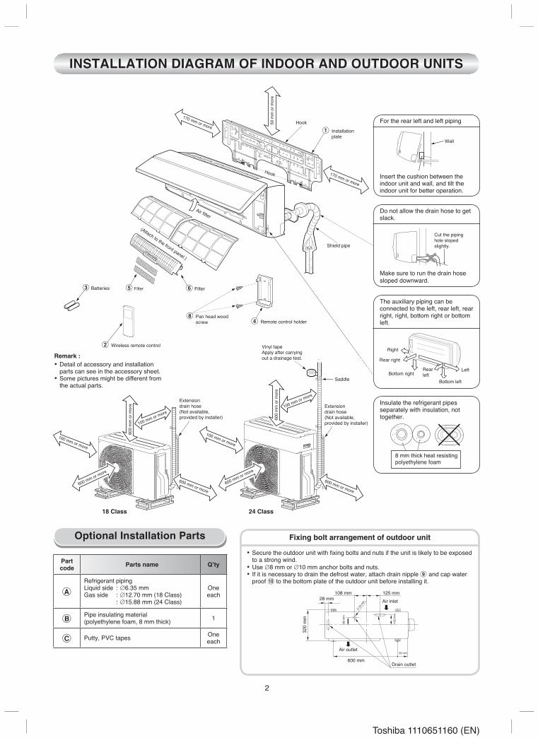
INSTALLATION DIAGRAM OF INDOOR AND OUTDOOR UNITS
Partcode Parts name Q’ty
A
Refrigerant pipingLiquid side : ∅6.35 mmGas side : ∅1�.70 mm (18 Class) : ∅15.88 mm (�4 Class)
Oneeach
BPipe insulating material(polyethylene foam, 8 mm thick) 1
C Putty, PVC tapes Oneeach
Optional Installation Parts• Secure the outdoor unit with fixing bolts and nuts if the unit is likely to be exposed
to a strong wind.• Use ∅8 mm or ∅10 mm anchor bolts and nuts.• If it is necessary to drain the defrost water, attach drain nipple 9 and cap water
proof ! to the bottom plate of the outdoor unit before installing it.
Fixing bolt arrangement of outdoor unit
Wall
(Attach to the front panel.)
For the rear left and left piping
Insert the cushion between the indoor unit and wall, and tilt the indoor unit for better operation.
Do not allow the drain hose to get slack.
Make sure to run the drain hose sloped downward.
Cut the piping hole sloped slightly.
The auxiliary piping can be connected to the left, rear left, rear right, right, bottom right or bottom left.
Right
Rear right
LeftBottom right
Rear left
Bottom left
Insulate the refrigerant pipes separately with insulation, not together.
8 mm thick heat resisting polyethylene foam
8 Pan head wood screw
3 Batteries
2 Wireless remote control
4 Remote control holder
6 Filter5 Filter
108 mm
600 mm
28 mm
25 m
m
90 mm
125 mm
320
mm
86 m
m
102
mm
Air outlet
Drain outlet
Air inlet
Vinyl tapeApply after carryingout a drainage test.
Saddle
Extensiondrain hose(Not available,provided by installer)
100 mm or more
100 mm or more
600 mm or more
600 mm or more
100 mm or more
600 mm or more
600 mm or more
600
mm
or m
ore
600
mm
or m
ore
100 mm or more
Extensiondrain hose(Not available,provided by installer)
18 Class 24 Class
Remark :• Detail of accessory and installation
parts can see in the accessory sheet.• Some pictures might be different from
the actual parts.
3
Toshiba 1110651160 (EN)
m from
the right side edge ise center of pipe hole
35 120 180 240
23 mm
65 mm
54 45
57
INDOOR UNIT
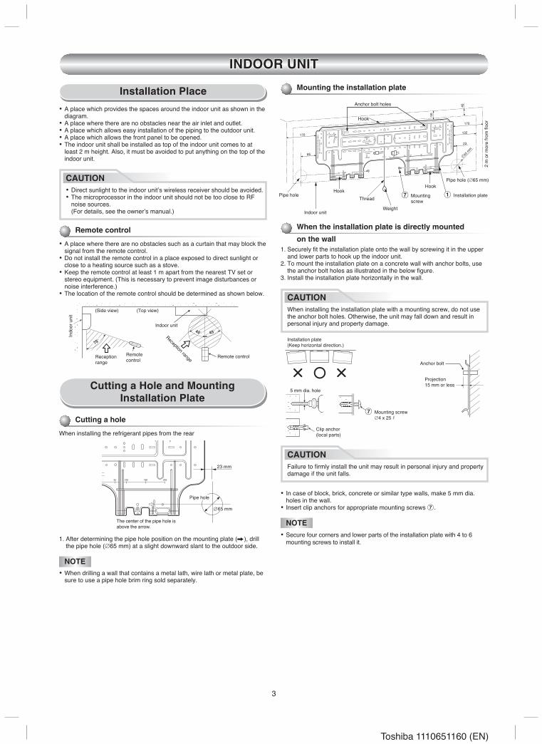
Installation Place
Remote control
• A place where there are no obstacles such as a curtain that may block the signal from the remote control.
• Do not install the remote control in a place exposed to direct sunlight or close to a heating source such as a stove.
• Keep the remote control at least 1 m apart from the nearest TV set or stereo equipment. (This is necessary to prevent image disturbances or noise interference.)
• The location of the remote control should be determined as shown below.
Cutting a Hole and MountingInstallation Plate
When the installation plate is directly mountedon the wall
1. Securely fi t the installation plate onto the wall by screwing it in the upper and lower parts to hook up the indoor unit.
�. To mount the installation plate on a concrete wall with anchor bolts, use the anchor bolt holes as illustrated in the below fi gure.
3. Install the installation plate horizontally in the wall.
NOTE• When drilling a wall that contains a metal lath, wire lath or metal plate, be
sure to use a pipe hole brim ring sold separately.
• A place which provides the spaces around the indoor unit as shown in the diagram.
• A place where there are no obstacles near the air inlet and outlet.• A place which allows easy installation of the piping to the outdoor unit.• A place which allows the front panel to be opened.• The indoor unit shall be installed as top of the indoor unit comes to at
least � m height. Also, it must be avoided to put anything on the top of the indoor unit.
The center of the pipe hole is above the arrow.
Pipe hole• In case of block, brick, concrete or similar type walls, make 5 mm dia.
holes in the wall.• Insert clip anchors for appropriate mounting screws 7.
Indo
or u
nit
(Side view) (Top view)
Indoor unit
Remote controlRemotecontrol
Receptionrange
Reception range
Installation plate(Keep horizontal direction.)
5 mm dia. hole
Clip anchor(local parts)
Anchor bolt
Projection15 mm or less
Cutting a hole
When installing the refrigerant pipes from the rear
Mounting the installation plate
NOTE• Secure four corners and lower parts of the installation plate with 4 to 6
mounting screws to install it.
CAUTION• Direct sunlight to the indoor unit’s wireless receiver should be avoided.• The microprocessor in the indoor unit should not be too close to RF
noise sources. (For details, see the owner’s manual.)
1. After determining the pipe hole position on the mounting plate (A), drill the pipe hole (∅65 mm) at a slight downward slant to the outdoor side.
7 Mounting screw ∅4 x �5 s
CAUTIONFailure to fi rmly install the unit may result in personal injury and property damage if the unit falls.
CAUTIONWhen installing the installation plate with a mounting screw, do not use the anchor bolt holes. Otherwise, the unit may fall down and result in personal injury and property damage.
To unit out line 240mm
To unit out line 35mm
To unit out line 240mm
Offset 23m
m from
the right side edge isthe center of pipe hole
To unit out line 120mm
0 23 35 120 180 240
Offs
et 8
5mm
from
the
left
side
edg
e is
the
cent
er o
f pip
e ho
le
170
170
50
40
85
132
23
65 m
m
Hook
HookHook
Pipe hole
Pipe hole (∅65 mm)
WeightIndoor unit
Thread
� m
or m
ore
from
fl oo
r
Anchor bolt holes
1 Installation plate7 Mounting screw
4
Toshiba 1110651160 (EN)
520 mm
420 mm
43 m
m
80
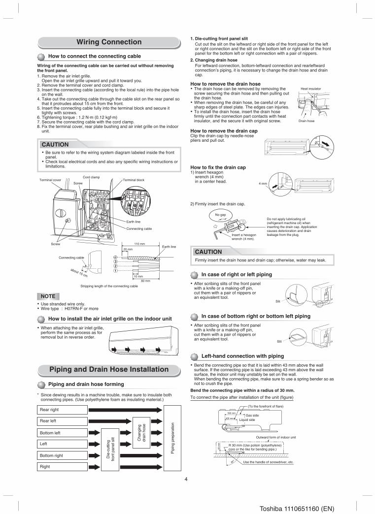
How to remove the drain capClip the drain cap by needle-nose pliers and pull out.
How to remove the drain hose• The drain hose can be removed by removing the
screw securing the drain hose and then pulling out the drain hose.
• When removing the drain hose, be careful of any sharp edges of steel plate. The edges can injuries.
• To install the drain hose, insert the drain hose fi rmly until the connection part contacts with heat insulator, and the secure it with original screw.
How to fi x the drain cap1) Insert hexagon wrench (4 mm) in a center head.
In case of right or left piping
• After scribing slits of the front panel with a knife or a making-off pin, cut them with a pair of nippers or an equivalent tool.
In case of bottom right or bottom left piping
• After scribing slits of the front panel with a knife or a making-off pin, cut them with a pair of nippers or an equivalent tool.
Liquid sideGas side
(To the forefront of fl are)
Outward form of indoor unit
R 30 mm (Use polisin (polyethylene)core or the like for bending pipe.)
Use the handle of screwdriver, etc.
Heat insulator
Drain hose
4 mm
Do not apply lubricating oil(refrigerant machine oil) wheninserting the drain cap. Applicationcauses deterioration and drainleakage from the plug.
Slit
Slit
1. Die-cutting front panel slit Cut out the slit on the leftward or right side of the front panel for the left
or right connection and the slit on the bottom left or right side of the front panel for the bottom left or right connection with a pair of nippers.
2. Changing drain hose For leftward connection, bottom-leftward connection and rearleftward
connection’s piping, it is necessary to change the drain hose and drain cap.
�) Firmly insert the drain cap.
No gap
CAUTIONFirmly insert the drain hose and drain cap; otherwise, water may leak.
Left-hand connection with piping
• Bend the connecting pipe so that it is laid within 43 mm above the wall surface. If the connecting pipe is laid exceeding 43 mm above the wall surface, the indoor unit may unstably be set on the wall.
When bending the connecting pipe, make sure to use a spring bender so as not to crush the pipe.
Bend the connecting pipe within a radius of 30 mm.To connect the pipe after installation of the unit (fi gure)
Insert a hexagonwrench (4 mm).
Piping and Drain Hose Installation
* Since dewing results in a machine trouble, make sure to insulate both connecting pipes. (Use polyethylene foam as insulating material.)
Piping and drain hose forming
How to install the air inlet grille on the indoor unit
• When attaching the air inlet grille, perform the same process as for removal but in reverse order.
Wiring Connection
How to connect the connecting cable
Wiring of the connecting cable can be carried out without removing the front panel.1. Remove the air inlet grille. Open the air inlet grille upward and pull it toward you.�. Remove the terminal cover and cord clamp.3. Insert the connecting cable (according to the local rule) into the pipe hole
on the wall.4. Take out the connecting cable through the cable slot on the rear panel so
that it protrudes about 15 cm from the front.5. Insert the connecting cable fully into the terminal block and secure it
tightly with screws.6. Tightening torque : 1.� N·m (0.1� kgf·m)7. Secure the connecting cable with the cord clamp.8. Fix the terminal cover, rear plate bushing and air inlet grille on the indoor
unit.
1 2 3
110 mm
20 mm
10 mm
80 mm
Earth line
about 15 cm
Rear right
Rear left
Bottom left
Left
Bottom right
Right
Die-
cutti
ngfro
nt p
anel
slit Ch
angi
ngdr
ain
hose
Pipi
ng p
repa
ratio
n
CAUTION• Be sure to refer to the wiring system diagram labeled inside the front
panel.• Check local electrical cords and also any specifi c wiring instructions or
limitations.
NOTE• Use stranded wire only.• Wire type : H07RN-F or more
ScrewTerminal cover Terminal block
Cord clamp
Screw
Earth line
Connecting cable
Connecting cable
Stripping length of the connecting cable
5
Toshiba 1110651160 (EN)
1
2
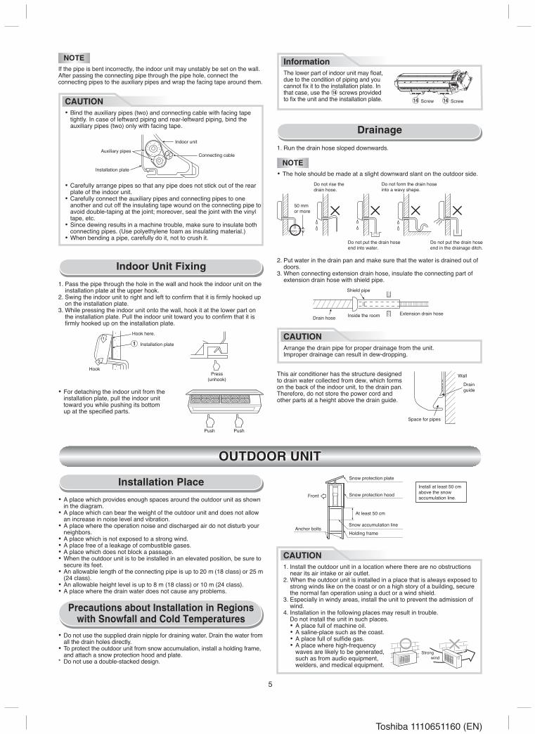
Indoor Unit Fixing
• For detaching the indoor unit from the installation plate, pull the indoor unit toward you while pushing its bottom up at the specifi ed parts.
1. Pass the pipe through the hole in the wall and hook the indoor unit on the installation plate at the upper hook.
�. Swing the indoor unit to right and left to confi rm that it is fi rmly hooked up on the installation plate.
3. While pressing the indoor unit onto the wall, hook it at the lower part on the installation plate. Pull the indoor unit toward you to confi rm that it is fi rmly hooked up on the installation plate.
Drainage1. Run the drain hose sloped downwards.
This air conditioner has the structure designed to drain water collected from dew, which forms on the back of the indoor unit, to the drain pan. Therefore, do not store the power cord and other parts at a height above the drain guide.
Hook here.
HookPress
(unhook)
Push Push
Do not rise thedrain hose.
Do not form the drain hose into a wavy shape.
50 mmor more
Do not put the drain hose end into water.
Do not put the drain hose end in the drainage ditch.
Shield pipe
Drain hoseExtension drain hoseInside the room
Wall
Drainguide
Space for pipes
NOTEIf the pipe is bent incorrectly, the indoor unit may unstably be set on the wall.After passing the connecting pipe through the pipe hole, connect the connecting pipes to the auxiliary pipes and wrap the facing tape around them.
CAUTION• Bind the auxiliary pipes (two) and connecting cable with facing tape
tightly. In case of leftward piping and rear-leftward piping, bind the auxiliary pipes (two) only with facing tape.
• Carefully arrange pipes so that any pipe does not stick out of the rear plate of the indoor unit.
• Carefully connect the auxiliary pipes and connecting pipes to one another and cut off the insulating tape wound on the connecting pipe to avoid double-taping at the joint; moreover, seal the joint with the vinyl tape, etc.
• Since dewing results in a machine trouble, make sure to insulate both connecting pipes. (Use polyethylene foam as insulating material.)
• When bending a pipe, carefully do it, not to crush it.
Auxiliary pipes
Indoor unit
Connecting cable
Installation plate
�. Put water in the drain pan and make sure that the water is drained out of doors.
3. When connecting extension drain hose, insulate the connecting part of extension drain hose with shield pipe.
NOTE• The hole should be made at a slight downward slant on the outdoor side.
CAUTIONArrange the drain pipe for proper drainage from the unit.Improper drainage can result in dew-dropping.
1 Installation plate
InformationThe lower part of indoor unit may fl oat, due to the condition of piping and you cannot fi x it to the installation plate. In that case, use the % screws provided to fi x the unit and the installation plate. % Screw % Screw
OUTDOOR UNIT
Installation Place• A place which provides enough spaces around the outdoor unit as shown
in the diagram.• A place which can bear the weight of the outdoor unit and does not allow
an increase in noise level and vibration.• A place where the operation noise and discharged air do not disturb your
neighbors.• A place which is not exposed to a strong wind.• A place free of a leakage of combustible gases.• A place which does not block a passage.• When the outdoor unit is to be installed in an elevated position, be sure to
secure its feet.• An allowable length of the connecting pipe is up to �0 m (18 class) or �5 m
(�4 class).• An allowable height level is up to 8 m (18 class) or 10 m (�4 class).• A place where the drain water does not cause any problems.
CAUTION1. Install the outdoor unit in a location where there are no obstructions
near its air intake or air outlet.�. When the outdoor unit is installed in a place that is always exposed to
strong winds like on the coast or on a high story of a building, secure the normal fan operation using a duct or a wind shield.
3. Especially in windy areas, install the unit to prevent the admission of wind.
4. Installation in the following places may result in trouble. Do not install the unit in such places. • A place full of machine oil. • A saline-place such as the coast. • A place full of sulfi de gas. • A place where high-frequency
waves are likely to be generated, such as from audio equipment,
welders, and medical equipment.
Strongwind
• Do not use the supplied drain nipple for draining water. Drain the water from all the drain holes directly.
• To protect the outdoor unit from snow accumulation, install a holding frame, and attach a snow protection hood and plate.
* Do not use a double-stacked design.
Precautions about Installation in Regions with Snowfall and Cold Temperatures
Snow protection plate
Snow protection hood
At least 50 cm
Snow accumulation line
Holding frame
Front
Anchor bolts
Install at least 50 cmabove the snowaccumulation line.
6
Toshiba 1110651160 (EN)
A
90
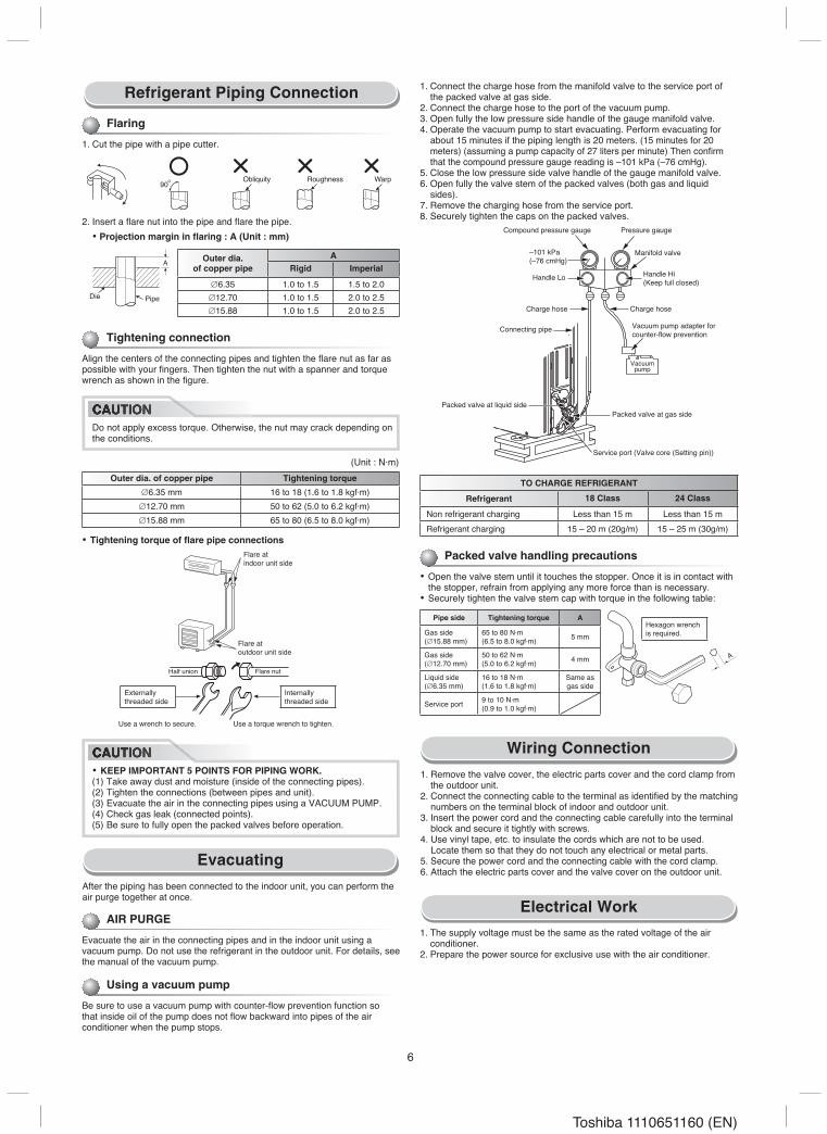
Refrigerant Piping Connection
Tightening connection
Align the centers of the connecting pipes and tighten the fl are nut as far as possible with your fi ngers. Then tighten the nut with a spanner and torque wrench as shown in the fi gure.
(Unit : N·m)Outer dia. of copper pipe Tightening torque
∅6.35 mm 16 to 18 (1.6 to 1.8 kgf·m)∅1�.70 mm 50 to 6� (5.0 to 6.� kgf·m)∅15.88 mm 65 to 80 (6.5 to 8.0 kgf·m)
Evacuating
• Tightening torque of flare pipe connections
Flaring
1. Cut the pipe with a pipe cutter.
Obliquity Roughness Warp
Half union Flare nut
PipeDie
Flare atindoor unit side
Flare atoutdoor unit side
Use a wrench to secure. Use a torque wrench to tighten.
Outer dia.of copper pipe
ARigid Imperial
∅6.35 1.0 to 1.5 1.5 to �.0∅1�.70 1.0 to 1.5 �.0 to �.5∅15.88 1.0 to 1.5 �.0 to �.5
CAUTIONDo not apply excess torque. Otherwise, the nut may crack depending on the conditions.
Internallythreaded side
Externallythreaded side
CAUTION• KEEP IMPORTANT 5 POINTS FOR PIPING WORK.(1) Take away dust and moisture (inside of the connecting pipes).(�) Tighten the connections (between pipes and unit).(3) Evacuate the air in the connecting pipes using a VACUUM PUMP.(4) Check gas leak (connected points).(5) Be sure to fully open the packed valves before operation.
After the piping has been connected to the indoor unit, you can perform the air purge together at once.
Using a vacuum pump
Be sure to use a vacuum pump with counter-fl ow prevention function so that inside oil of the pump does not fl ow backward into pipes of the air conditioner when the pump stops.
A
1. Connect the charge hose from the manifold valve to the service port of the packed valve at gas side.
�. Connect the charge hose to the port of the vacuum pump.3. Open fully the low pressure side handle of the gauge manifold valve.4. Operate the vacuum pump to start evacuating. Perform evacuating for
about 15 minutes if the piping length is �0 meters. (15 minutes for �0 meters) (assuming a pump capacity of �7 liters per minute) Then confi rm that the compound pressure gauge reading is –101 kPa (–76 cmHg).
5. Close the low pressure side valve handle of the gauge manifold valve.6. Open fully the valve stem of the packed valves (both gas and liquid
sides).7. Remove the charging hose from the service port.8. Securely tighten the caps on the packed valves.
Packed valve at liquid side
Vacuumpump
Handle Lo
–101 kPa(–76 cmHg)
Packed valve handling precautions
• Open the valve stem until it touches the stopper. Once it is in contact with the stopper, refrain from applying any more force than is necessary.
• Securely tighten the valve stem cap with torque in the following table:
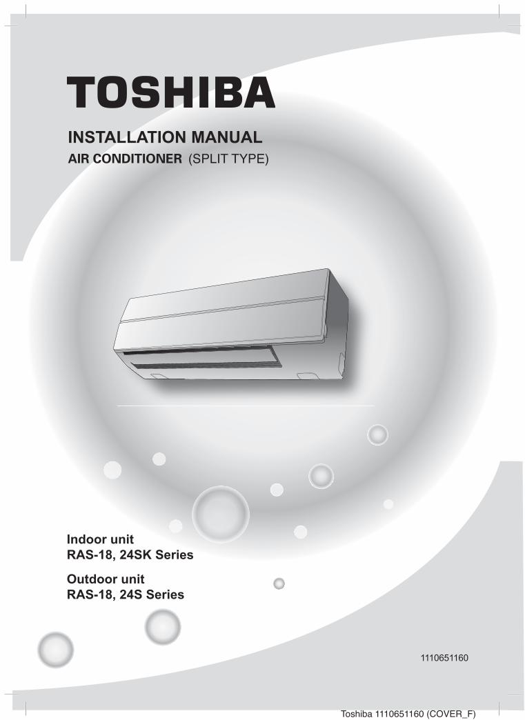
Wiring Connection1. Remove the valve cover, the electric parts cover and the cord clamp from
the outdoor unit.�. Connect the connecting cable to the terminal as identifi ed by the matching
numbers on the terminal block of indoor and outdoor unit.3. Insert the power cord and the connecting cable carefully into the terminal
block and secure it tightly with screws.4. Use vinyl tape, etc. to insulate the cords which are not to be used. Locate them so that they do not touch any electrical or metal parts.5. Secure the power cord and the connecting cable with the cord clamp.6. Attach the electric parts cover and the valve cover on the outdoor unit.
Electrical Work1. The supply voltage must be the same as the rated voltage of the air
conditioner.�. Prepare the power source for exclusive use with the air conditioner.
TO CHARGE REFRIGERANT
Refrigerant 18 Class 24 Class
Non refrigerant charging Less than 15 m Less than 15 mRefrigerant charging 15 – �0 m (�0g/m) 15 – �5 m (30g/m)
Hexagon wrenchis required.
Pipe side Tightening torque A
Gas side(∅15.88 mm)
65 to 80 N·m(6.5 to 8.0 kgf·m) 5 mm
Gas side(∅1�.70 mm)
50 to 6� N·m(5.0 to 6.� kgf·m) 4 mm
Liquid side(∅6.35 mm)
16 to 18 N·m(1.6 to 1.8 kgf·m)
Same asgas side
Service port 9 to 10 N·m(0.9 to 1.0 kgf·m)
Vacuum pump adapter forcounter-fl ow prevention
AIR PURGE
Evacuate the air in the connecting pipes and in the indoor unit using a vacuum pump. Do not use the refrigerant in the outdoor unit. For details, see the manual of the vacuum pump.
Service port (Valve core (Setting pin))
Charge hose Charge hose
Manifold valve
Pressure gaugeCompound pressure gauge
Handle Hi(Keep full closed)
Connecting pipe
Packed valve at gas side
�. Insert a fl are nut into the pipe and fl are the pipe. • Projection margin in flaring : A (Unit : mm)
CAUTION
CAUTION
7
Toshiba 1110651160 (EN)
AB
OTHERS
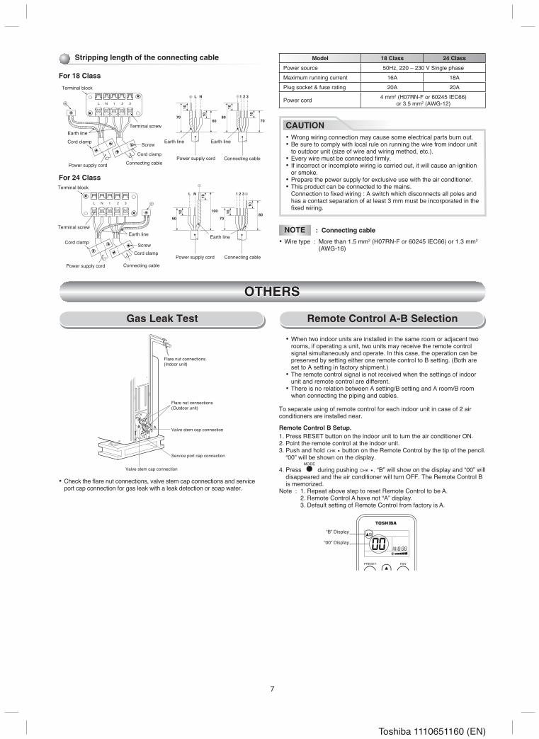
Gas Leak Test Remote Control A-B Selection
“B” Display
“00” Display
To separate using of remote control for each indoor unit in case of � air conditioners are installed near.
Remote Control B Setup.1. Press RESET button on the indoor unit to turn the air conditioner ON.�. Point the remote control at the indoor unit.3. Push and hold button on the Remote Control by the tip of the pencil.
“00” will be shown on the display.
4. Press during pushing . “B” will show on the display and “00” will disappeared and the air conditioner will turn OFF. The Remote Control B is memorized.
Note : 1. Repeat above step to reset Remote Control to be A. �. Remote Control A have not “A” display. 3. Default setting of Remote Control from factory is A.
• Check the fl are nut connections, valve stem cap connections and service port cap connection for gas leak with a leak detection or soap water.
Model 18 Class 24 Class
Power source 50Hz, ��0 – �30 V Single phaseMaximum running current 16A 18APlug socket & fuse rating �0A �0A
Power cord 4 mm� (H07RN-F or 60�45 IEC66) or 3.5 mm� (AWG-1�)
70
L N
10
60
10
70
10
80 10
1 2 3
L N 1 32
Terminal block
Earth line
Cord clamp
Earth lineTerminal screw
Cord clamp Screw
Power supply cord Connecting cablePower supply cord Connecting cable
100
60
L N
10
70
10 80
10
1 2 3
10
Earth line
Power supply cord Connecting cable
L N 1 32
Terminal block
Cord clamp
Earth lineTerminal screw
Cord clamp Screw
Power supply cord Connecting cable
For 18 Class
For 24 Class
Earth line
Stripping length of the connecting cable
CAUTION• Wrong wiring connection may cause some electrical parts burn out.• Be sure to comply with local rule on running the wire from indoor unit
to outdoor unit (size of wire and wiring method, etc.).• Every wire must be connected fi rmly.• If incorrect or incomplete wiring is carried out, it will cause an ignition
or smoke.• Prepare the power supply for exclusive use with the air conditioner.• This product can be connected to the mains. Connection to fi xed wiring : A switch which disconnects all poles and
has a contact separation of at least 3 mm must be incorporated in the fi xed wiring.
NOTE : Connecting cable
• Wire type : More than 1.5 mm� (H07RN-F or 60�45 IEC66) or 1.3 mm� (AWG-16)
Service port cap connection
Valve stem cap connection
Flare nut connections(Outdoor unit)
Flare nut connections (Indoor unit)
Valve stem cap connection
PRESET FAN
• When two indoor units are installed in the same room or adjacent two rooms, if operating a unit, two units may receive the remote control signal simultaneously and operate. In this case, the operation can be preserved by setting either one remote control to B setting. (Both are set to A setting in factory shipment.)
• The remote control signal is not received when the settings of indoor unit and remote control are different.
• There is no relation between A setting/B setting and A room/B room when connecting the piping and cables.
8
Toshiba 1110651160 (EN)
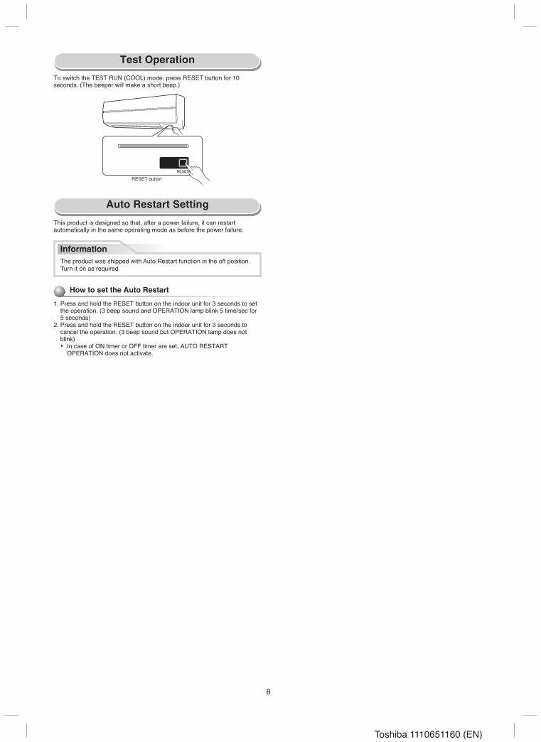
Test Operation
Auto Restart Setting
How to set the Auto Restart
1. Press and hold the RESET button on the indoor unit for 3 seconds to set the operation. (3 beep sound and OPERATION lamp blink 5 time/sec for 5 seconds)
�. Press and hold the RESET button on the indoor unit for 3 seconds to cancel the operation. (3 beep sound but OPERATION lamp does not blink)
• In case of ON timer or OFF timer are set, AUTO RESTART OPERATION does not activate.
This product is designed so that, after a power failure, it can restart automatically in the same operating mode as before the power failure.
To switch the TEST RUN (COOL) mode, press RESET button for 10 seconds. (The beeper will make a short beep.)
RESET
Hi POWER FILTER PAP TIMER OPERATION
RESET button
InformationThe product was shipped with Auto Restart function in the off position. Turn it on as required.