Embed Size (px)
Citation preview

0
Agility Training
AGILITY 50

1
SPECIFCATIONS
Motorcycle Name & Type AGILITY 50 Name & Model No. KG10SA Overall length (mm) 1830 Overall width (mm) 690 Overall height (mm) 1130 Wheel base (mm) 1325 Engine type O.H.C. Displacement 49.5cc Fuel Used 92# nonleaded gasoline Front wheel 37.5 Net weight (kg) Rear wheel 55 Total 92.5 Front wheel 38 Gross weight(kg) Rear wheel 59 Total 97
Front wheel 120/70 -12 56J Tires Rear wheel 130/70 -12 59J Ground clearance (mm) 125
Perform- Braking distance (m) 4 (Initial speed 30km/h)
ance Min. turning radius (m) 1.99 Starting system Starting motor &
kick starter Type Gasoline, 4-stroke Cylinder arrangement Single cylinder Combustion chamber type Semi-sphere Valve arrangement O.H.C. Bore x stroke (mm) φ39.0 x 41.4 Compression ratio 11 Compression pressure
(kg/cm²-rpm) 18
Max. output (ps/rpm) 3.5/7500 Max. torque (kg m/rpm) 0.32/7000 Open 3° Valve
Intake Close 11°
Engine
timing Open -9° Exhaust Close 19° Valve clearance Intake 0.04 (cold) (mm) Exhaust 0.04 Idle speed (rpm) 1700±100rpm Lubrication type Forced pressure &
wet sump Oil pump type Inner/outer rotor type Oil filter type Full-flow filtration
Lubrication System
Oil capacity 0.85 liter Cooling Type Forced air cooling
Air cleaner type & No Paper element, wet Fuel capacity 5.0 liter Type CVK Piston dia. (mm) Venturi dia.(mm) φ17equivalent
Carburetor Throttle type Butterfly type
Type CDI Ignition timing BTDC28°/4000rpm
Contact breaker Non-contact point type
Spark plug
NGK
CR7HSA
Spark plug gap 0.6~ 0.7mm Battery Capacity 12V4AH Clutch Type Dry multi-disc clutch Type Non-stage transmission
Operation Automatic centrifugal type
Type Two-stage reduction
Reduction 1st 0.75-2.47 ratio 2nd 13.61 Front Caster angle 27°
Axle Trail length
Tire pressure Front 1.75 (kg/cm²) Rear 2.25 Turning Left 45° angle Right 45°
Front DISK (180mm) brake Brake system
type Rear Drum (110mm) brake
Front TELESCOPE Suspension type Rear Unit Swing Front 80
Shock absorber distance Rear 82
Frame type Under Bone
Fuel System
Electrical Equipment
Ignition System
Power D
rive System
Transm
is-sion G
ear R
eduction G
ear
Moving D
evice D
amping
Device

2
ENGINE 1.CYLINDER HEAD/VALVES Service information 1.Before camshaft removal, turn the flywheel counterclockwise so that the “T” mark on the flywheel aligns with the index mark on the crankcase to bring the round hole on the camshaft gear facing up to the top dead center on the compression stroke. 2.Diagonally loosen and tighten the cylinder head nuts in 2 or 3 times. Torque : 1.8~2.2 kgf.m. 3.Apply engine oil to the valve shaft, rocker arm shaft, threads of the cylinder head nuts when you be installation. 4.Installation spark plug. Torque : 1.1~1.7 kgf.m. 5.Specified spark plug : NGK-CR7HSA Gap : 0.6~0.7mm. 6.Remove the valve spring cotters, retainers, springs, spring seats and valve stem seals using a special tool. After installation, tap the valve stems gently with a plastic hammer for 2~3 times to firmly seat the cotters. 7.Inspect and adjust the valve clearance. Valve clearance IN/EX: 0.12mm
Round Hole
Punch Marks Tap Position

3
2.CYLINDER/PISTION/PISTION RING Service information 1.Replace a new gasket and confirm position of dowel pins when be installation cylinder. 2.Place a clean shop towel in the crankcase to keep the piston pin clip from falling into the crankcase when remove the piston pin clip. 3.Take care not to damage or break the piston rings during removal. 4.All rings should be installed with the markings facing up. After installing the ring, they should rotate freely without sticking then stagger the ring end gaps at 120º to the piston pin. 5.Positon the piston “IN” mark on the intake valve side, the “EX” marks on the outtake valve side. 6.Install the piston pin clip avoided the gap same position with the piston of indentation. 7.Avoid come off the chain when install the cylinder.
Dowel Pins
Side Rail
Top
Second
Piston Pin Clip
Oil Ring Side Rail
Top
Second

4
3.CVT Service information 1.Left crankcase cover there are eight bolts and two dowel pins, a seal rubber. Torque : 1.0~1.4kgf.m. 2.Start system removal: starter driven gear? return? kick lever? starter shaft clip? starter shaft. The installation sequence is the reverse of removal. 3.Hold the drive pulley face/clutch outer using an universal holder then remove the drive face/clutch outer nuts. Drive pulley face nut torque: 5.5~6.5 kgf-m. Clutch outer nut torque: 5.0~6.0 kgf-m. 4.Put the weight rollers plastic part into the movable drive face by counterclockwise. 5.Drive belt use specified genuine parts for replacement, install the belt into the clutch then confirm the mark at the front. 6.Measure the drive belt width. Service limit: 19.0mm replace if below Universal Holder Dowel Pins

5
4.OIL PUMP/A.C.GENERATOR Service information 1.Right crankcase there are eight blots. Torque: 0.8~1.2kgf.m. 2.Hold the flywheel with an universal holder. Torque: 5.0~6.0kgf.m. 3.Remove the A.C. generator flywheel using the flywheel puller. Install the flywheel onto the crankshaft with the flywheel hole aligned with the crankshaft woodruff key. 4.Change engine oil at first 300km and then change it at every 2000km. If the level is near the lower level, fill to the upper level with the specified engine oil. 5.Replace/Clean the oil filter screen at every 5000km or 6 month. Torque: 1.3~1.7kgf.m. 6.Measure the resistance between the A.C. generator white wire and engine ground(0.1~1.0Ω), the yellow and engine ground(0.2~1.2Ω), and the pulser coil wire blue/yellow and green(40~300Ω) with an electric tester.
7.Fill with the specified SAE15W40#, API:SG/CD engine oil to the proper level. Oil capacity a t disassembly: 0.90 liter, at change: 0.75 liter. Torque: 1.3~1.7kgf.m.

6
5.CRANKSHAFT Service information 1.Avoid damaging the crankcase mating surfaces when removes the crankcase. 2.Turn the crankshaft bearings and check for excessive play, if they do not turn smoothly, quietly or fit loosely in the crankshaft, replace the crankshaft as a set. 3.Clean off all gasket material from the crankcase mating surfaces then install the new gasket and two dowel pins. 4.Confirm the connecting rod position when you install the crankshaft, besides avoided the crankshaft force into the left crankcase. 5.Crankcase bolts torque: 0.8~1.2kgf.m.
Blots Dowel Pins
Gasket
7
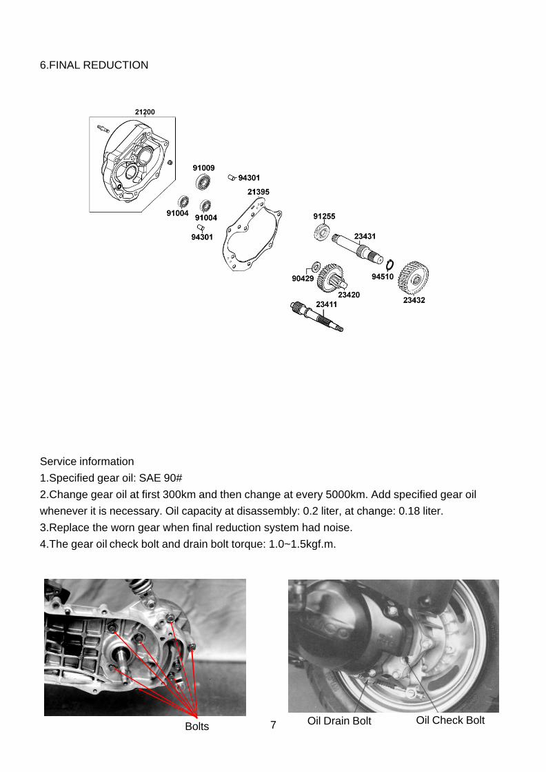
6.FINAL REDUCTION Service information 1.Specified gear oil: SAE 90# 2.Change gear oil at first 300km and then change at every 5000km. Add specified gear oil whenever it is necessary. Oil capacity at disassembly: 0.2 liter, at change: 0.18 liter. 3.Replace the worn gear when final reduction system had noise. 4.The gear oil check bolt and drain bolt torque: 1.0~1.5kgf.m.
Bolts Oil Drain Bolt Oil Check Bolt

8
7.CARBURETOR Service information 1.When working with gasoline keeps sparks and flames away from the working area. Be sure to work in a well-ventilated area. 2.Before float chamber disassembly, loosen the drain screw to drain the residual gasoline into a clean container. 3.Remove the vacuum diaphragm before cleaning the carburetor air and fuel passages with compressed air to avoid damaging the vacuum diaphragm. 4.Before removing, turn the pilot screw in and carefully count the number of turns until it seats lightly and then make a note of this. Return the pilot screw to the original position as noted during removal. Standard opening:2 ? ± ¾, including parts there are pilot screw, spring, washer, o-ring. 5.Float valve and valve seat must be replaced because it will result in float level too high due to incomplete airtightness. Float level: 18.5mm. 6.Check the auto bystarter valve and needle for nicks, wear or damage. If any faulty part is found, replace the auto bystarter as a set. Measure the resistance between the auto bystarter wire terminals. Resistance: 5? max.(10 minutes minimum after stopping the engine) 7.After cleaned the carburetor blow compressed air through all passages of the carburetor body. Main jet standard: #96, Slow jet standard: #35.
Slow Jet

9
CHASSIS FRAME
1.When removing frame cover, use special care not to pull them by force because the cover joint claws may be damaged. 2.Make sure to route cables and harnesses according to the cable & harness routing. 3.Exhaust muffler lock bolt torque: 3.2~3.8kgf-m, Exhaust muffler joint lock nut: 1.8~2.2kgf-m 4.Rear shock absorber upper mount bolt torque: 3.5~4.5kgf-m, Rear shock absorber lower mount bolt torque: 3.5~4.5kgf-m.
Pilot Screw Main Jet Air Compress Implement

10
5.Steering stem bolt torque: 4.0~5.0kgf-m, Steering top cone race torque: 0.5~1.3kgf-m, Steering stem lock nut torque: 8.0~12.0kgf-m 6.Front wheel torque: 5.0~7.0kgf-m, Rear wheel torque: 11.0~13.0kgf-m. 7.Brake caliper bolts torque: 2.9~3.5kgf-m. 8.Engine hanger bracket bolts torque: 4.5~5.5kgf-m.

11
ELECTRICAL EOUIPMENT 1. Circuitry
12
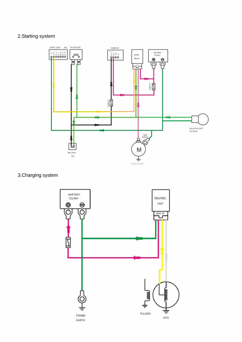
2.Starting system 3.Charging system

13
4.Ignition system 5.A.C electric

14
5.D.C electric