Embed Size (px)
Citation preview
Agilent Technologies
Agilent 1100 Series Valves
Operator’s Manual
ii Agilent 1100 Series Valves
Notices© Agilent Technologies, Inc. 2002
No part of this manual may be reproduced in any form or by any means (including elec-tronic storage and retrieval or translation into a foreign language) without prior agree-ment and written consent from Agilent Technologies, Inc. as governed by United States and international copyright laws.
Manual Part NumberG1156-90000
Edition08/2002
Printed in Germany
Agilent Technologies Deutschland GmbHHewlett-Packard-Strasse 8 76337 Waldbronn, Germany
WarrantyThe material contained in this docu-ment is provided “as is,” and is sub-ject to being changed, without notice, in future editions. Further, to the max-imum extent permitted by applicable law, Agilent disclaims all warranties, either express or implied, with regard to this manual and any information contained herein, including but not limited to the implied warranties of merchantability and fitness for a par-ticular purpose. Agilent shall not be liable for errors or for incidental or consequential damages in connec-tion with the furnishing, use, or per-formance of this document or of any information contained herein. Should Agilent and the user have a separate written agreement with warranty terms covering the material in this document that conflict with these terms, the warranty terms in the sep-arate agreement shall control.
Technology Licenses The hardware and/or software described in this document are furnished under a license and may be used or copied only in accor-dance with the terms of such license.
Restricted Rights LegendIf software is for use in the performance of a U.S. Government prime contract or subcon-tract, Software is delivered and licensed as “Commercial computer software” as defined in DFAR 252.227-7014 (June 1995), or as a “commercial item” as defined in FAR 2.101(a) or as “Restricted computer soft-ware” as defined in FAR 52.227-19 (June 1987) or any equivalent agency regulation or contract clause. Use, duplication or disclo-sure of Software is subject to Agilent Tech-nologies’ standard commercial license terms, and non-DOD Departments and Agencies of the U.S. Government will receive no greater than Restricted Rights as
defined in FAR 52.227-19(c)(1-2) (June 1987). U.S. Government users will receive no greater than Limited Rights as defined in FAR 52.227-14 (June 1987) or DFAR 252.227-7015 (b)(2) (November 1995), as applicable in any technical data.
Safety Notices
CAUTION
A CAUTION notice denotes a haz-ard. It calls attention to an operat-ing procedure, practice, or the like that, if not correctly performed or adhered to, could result in damage to the product or loss of important data. Do not proceed beyond a CAUTION notice until the indicated conditions are fully understood and met.
WARNING
A WARNING notice denotes a hazard. It calls attention to an operating procedure, practice, or the like that, if not correctly per-formed or adhered to, could result in personal injury or death. Do not proceed beyond a WARNING notice until the indicated condi-tions are fully understood and met.
Agilent 1100 Series Valves iii
In this Manual, you will find ...
The Agilent 1100 Series valves provide the user comprehensive solutions for more flexibility through solvent selection and column selection. They offer new automation capabilities for sample preparation as well as higher sample throughput with alternating column regeneration. The Agilent 1100 Series valves are fully integrated in the CAN environment (control area network) of the Agilent 1100 HPLC system and can be controlled by the Agilent ChemStation Software. The following types of valves will be described in this manual:
• G1157A Agilent 1100 Series 2 Position/10 Port Valve
• G1158A Agilent 1100 Series 2 Position/ 6 Port Valve
• G1159A Agilent 1100 Series 6 Position Selection Valve
• G1160A Agilent 1100 Series 12 Position/13 Port Selection Valve
These valves and the corresponding capillary kits for alternating column regeneration, sample enrichment, sample clean-up, column selection or solvent selection will allow you to implement these applications easily.
Chapter 1, “Installation and Configuration,” starting on page 1 will describe how to install and configure the 1100 Series valves.
Chapter 2, “Operation,” starting on page 11 will describe the Agilent ChemStation valve interface and how to setup the valves in your analytical method.
Chapter 3, “Maintenance, Repair, and Troubleshooting,” starting on page 17 will describe recommended maintenance and repair procedures as well as troubleshooting tools.
Chapter 4, “Valve Applications,” starting on page 29 will describe common application, e.g. alternating column regeneration, and how to setup your valves for these applications.

iv Agilent 1100 Series Valves
contents
Agilent 1100 Series Valves i
Contents
1 Installation and Configuration
Site Requirements 2
Unpacking the 1100 Series Valve 3
Damaged Packaging 3Delivery Checklist 3
Hardware Installation 5
Setting up the CAN connection 6Setting up the power connection to other Agilent 1100 Series
Modules 7Setting up the power connection to the external power
supply 7
Software Configuration 8
2 Operation
Operating the Valve using Agilent ChemStation 12
Handheld Controller functions 15
3 Maintenance, Repair, and Troubleshooting
Maintenance and Repair 18
Replacing the stator face and the rotor seal 18Early Maintenance Feedback (EMF) 22
System Errors and Troubleshooting 24
System Errors 24Valve Synchronization 27
4 Valve Applications
Alternating Column Regeneration 30
Sample enrichment and Sample stripping 34
ii Agilent 1100 Series Valves
contents
Sample enrichment 34Sample stripping 35
Column Selection 38
Solvent Selection 40
5 Parts
6 Specifications
Index 49
1
Agilent 1100 Agilent 1100 Series ValvesOperator’s Manual
Agilent Technologies
1Installation and Configuration
Site Requirements 2
Unpacking the 1100 Series Valve 3
Hardware Installation 5
Software Configuration 8
2 Agilent 1100 Series Valves
1 Installation and ConfigurationSite Requirements
Site Requirements
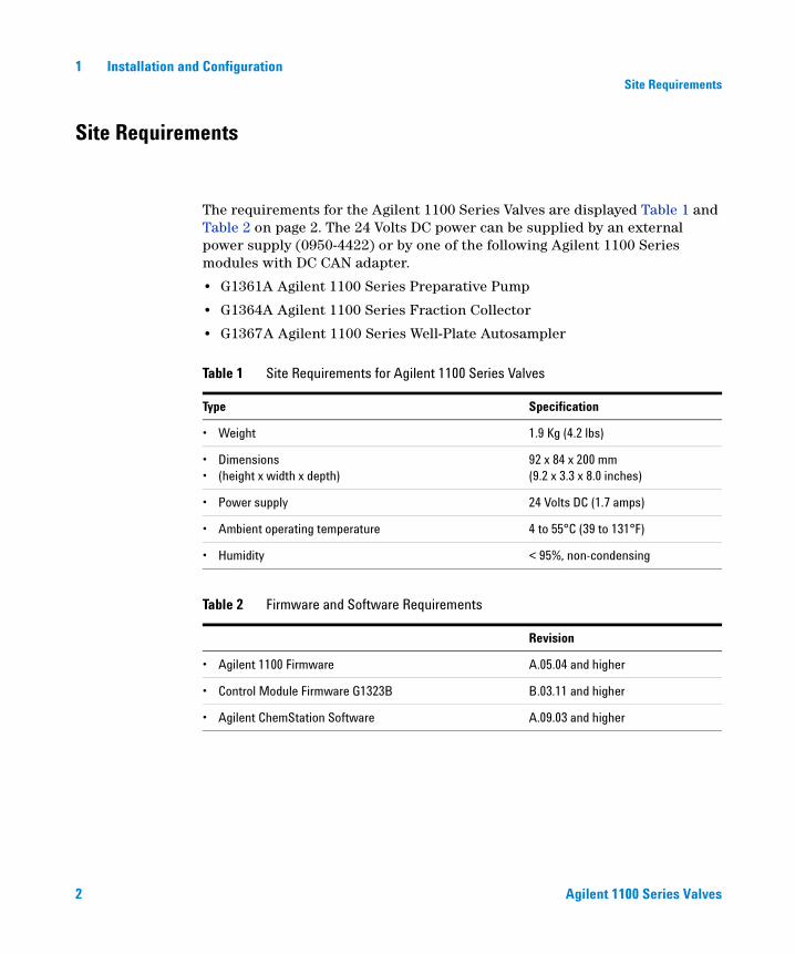
The requirements for the Agilent 1100 Series Valves are displayed Table 1 and Table 2 on page 2. The 24 Volts DC power can be supplied by an external power supply (0950-4422) or by one of the following Agilent 1100 Series modules with DC CAN adapter.
• G1361A Agilent 1100 Series Preparative Pump
• G1364A Agilent 1100 Series Fraction Collector
• G1367A Agilent 1100 Series Well-Plate Autosampler
Table 1 Site Requirements for Agilent 1100 Series Valves
Type Specification
• Weight 1.9 Kg (4.2 lbs)
• Dimensions• (height x width x depth)
92 x 84 x 200 mm(9.2 x 3.3 x 8.0 inches)
• Power supply 24 Volts DC (1.7 amps)
• Ambient operating temperature 4 to 55°C (39 to 131°F)
• Humidity < 95%, non-condensing
Table 2 Firmware and Software Requirements
Revision
• Agilent 1100 Firmware A.05.04 and higher
• Control Module Firmware G1323B B.03.11 and higher
• Agilent ChemStation Software A.09.03 and higher
Agilent 1100 Series Valves 3
Installation and Configuration 1Unpacking the 1100 Series Valve
Unpacking the 1100 Series Valve
Damaged Packaging
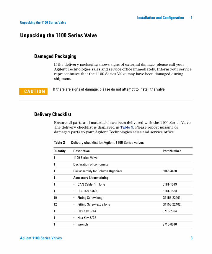
If the delivery packaging shows signs of external damage, please call your Agilent Technologies sales and service office immediately. Inform your service representative that the 1100 Series Valve may have been damaged during shipment.
Delivery Checklist
Ensure all parts and materials have been delivered with the 1100 Series Valve. The delivery checklist is displayed in Table 3. Please report missing or damaged parts to your Agilent Technologies sales and service office.
CAUTION If there are signs of damage, please do not attempt to install the valve.
Table 3 Delivery checklist for Agilent 1100 Series valves
Quantity Description Part Number
1 1100 Series Valve
1 Declaration of conformity
1 Rail assembly for Column Organizer 5065-4450
1 Accessory kit containing
1 • CAN Cable, 1m long 5181-1519
1 • DC-CAN cable 5181-1533
10 • Fitting Screw long G1156-22401
12 • Fitting Screw extra long G1156-22402
1 • Hex Key 9/64 8710-2394
1 • Hex Key 3/32
1 • wrench 8710-0510
4 Agilent 1100 Series Valves
1 Installation and ConfigurationUnpacking the 1100 Series Valve
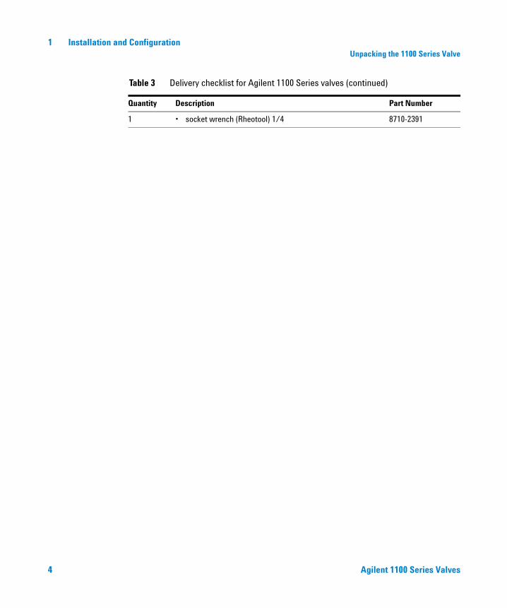
1 • socket wrench (Rheotool) 1/4 8710-2391
Table 3 Delivery checklist for Agilent 1100 Series valves (continued)
Quantity Description Part Number
Agilent 1100 Series Valves 5
Installation and Configuration 1Hardware Installation
Hardware Installation
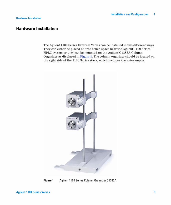
The Agilent 1100 Series External Valves can be installed in two different ways. They can either be placed on free bench space near the Agilent 1100 Series HPLC system or they can be mounted on the Agilent G1383A Column Organizer as displayed in Figure 1. The column organizer should be located on the right side of the 1100 Series stack, which includes the autosampler.
Figure 1 Agilent 1100 Series Column Organizer G1383A
6 Agilent 1100 Series Valves
1 Installation and ConfigurationHardware Installation
In order to install a valve on the G1383A Column Organizer the Organizer Rail Assembly must be installed on the two mounting poles using the clips from the Organizer Rail Assembly. All External Valves have a bracket on the side which slides over the metal part of the Organizer Rail Assembly.
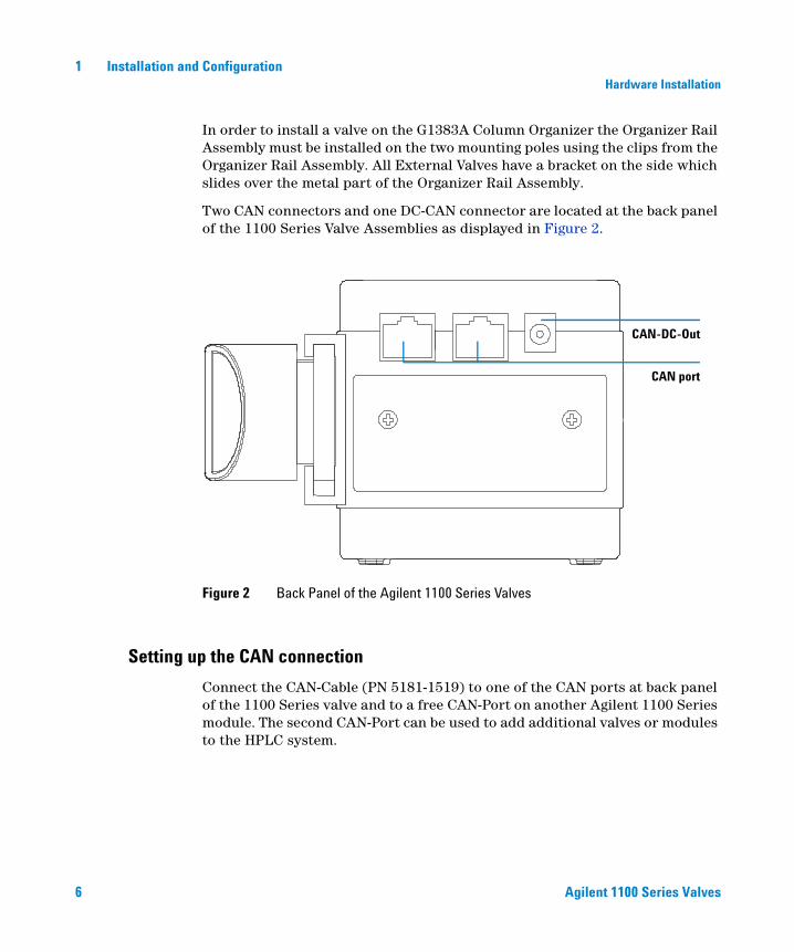
Two CAN connectors and one DC-CAN connector are located at the back panel of the 1100 Series Valve Assemblies as displayed in Figure 2.
Setting up the CAN connection
Connect the CAN-Cable (PN 5181-1519) to one of the CAN ports at back panel of the 1100 Series valve and to a free CAN-Port on another Agilent 1100 Series module. The second CAN-Port can be used to add additional valves or modules to the HPLC system.
Figure 2 Back Panel of the Agilent 1100 Series Valves
CAN-DC-Out
CAN port
Agilent 1100 Series Valves 7
Installation and Configuration 1Hardware Installation
Setting up the power connection to other Agilent 1100 Series Modules
The power for the Agilent 1100 Series External Valves can be supplied by one of the following 1100 Series modules:
• G1361A Agilent 1100 Series Preparative Pump
• G1364A Agilent 1100 Series Fraction Collector
• G1367A Agilent 1100 Series Well-Plate Autosampler
Connect the DC-CAN Cable (PN 5181-1533) to the DC-CAN connector at the back panel of the valve and to the DC-CAN connector on one of the Agilent 1100 Series modules listed above.
Setting up the power connection to the external power supply
If none of the Agilent 1100 Series modules from the list above is part of your HPLC system, you have to supply the power through an external power supply (P/N 0950-4422). Plug the DC-CAN adapter from the power supply into the DC-CAN connector on the back panel of your 1100 Series External Valve.

8 Agilent 1100 Series Valves
1 Installation and ConfigurationSoftware Configuration
Software Configuration
The 1100 Series Valves can be controlled by the Agilent ChemStation Rev. A.09.03 or higher.
To configure the 1100 Series Valves
Step Note
1 Start the Agilent ChemStation Software.
2 Select Configure 1100 Access in the Instrument menu.
3 In the upcoming Configuration dialog box select one or multiple valves and click Add.
The selected green valve icon now moves from the left Available Modules panel to the right Configured Modules panel as displayed in Figure 3 on page 9.
4 Click OK to leave the Configuration dialog box.
5 After a Restart the Agilent ChemStation Software a new menu item Setup Valve now appears in the Instrument menu.

Agilent 1100 Series Valves 9
Installation and Configuration 1Software Configuration
Figure 3 Valve configuration

10 Agilent 1100 Series Valves
1 Installation and ConfigurationSoftware Configuration
11
Agilent 1100 Agilent 1100 Series ValvesOperator’s Manual
Agilent Technologies
2Operation
Operating the Valve using Agilent ChemStation 12
Handheld Controller functions 15
12 Agilent 1100 Series Valves
2 OperationOperating the Valve using Agilent ChemStation
Operating the Valve using Agilent ChemStation
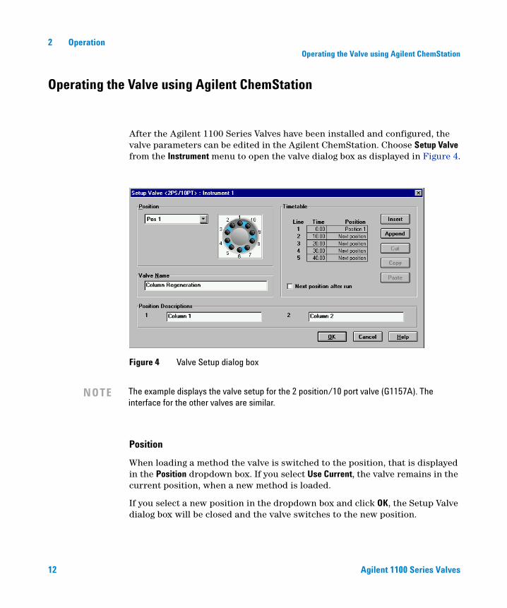
After the Agilent 1100 Series Valves have been installed and configured, the valve parameters can be edited in the Agilent ChemStation. Choose Setup Valve from the Instrument menu to open the valve dialog box as displayed in Figure 4.
Position
When loading a method the valve is switched to the position, that is displayed in the Position dropdown box. If you select Use Current, the valve remains in the current position, when a new method is loaded.
If you select a new position in the dropdown box and click OK, the Setup Valve dialog box will be closed and the valve switches to the new position.
Figure 4 Valve Setup dialog box
NOTE The example displays the valve setup for the 2 position/10 port valve (G1157A). The interface for the other valves are similar.
Agilent 1100 Series Valves 13
Operation 2Operating the Valve using Agilent ChemStation
Valve Name
Define the Valve Name that is used for the method report and the Instrument actuals. The Valve Name is limited to 20 characters.
Position Descriptions
Define the Position Description that is used for the method report and the instrument actuals. The Position Description is limited to 19 characters.
Time Table
The Time Table can be used to edit and run a valve program during a sequence of sample runs. The Time Table contains 3 columns (Line, Time and Position). The Time Table is limited to 20 lines. The number of selection in the Position column depends on the valve that has been configured.
Table 4 Available valve positions
Valve Description Product Number # of Positions Descriptions
2 position / 10 port valve G1157A 2
2 position / 6 port valve G1158A 2
6 position selection valve G1159A 6
12 position / 13 port selection valve G1160A 12
Position X switches the valve to the selected position. The number of available positions for the 1100 series valves is displayed in Table 4.
Next Position switches to the next available position. If the valve is on the highest position it will switch to position 1.
Insert Inserts a line in the Time Table above the selected position.
Append Appends a line at the end of the Time Table.
Cut Cuts the selected line(s) out of the Time Table and saves it to the clipboard.
Copy Copies the selected line(s) from the table to the clipboard.
Paste Pastes line(s) from the Clipboard to the Time Table.
14 Agilent 1100 Series Valves
2 OperationOperating the Valve using Agilent ChemStation
Next position after run
If Next position after run is checked, the valve will switch to the next available position after the run is completed. You also have to select Use Current in the position dropdown list, otherwise the position defined in the Position dropdown list will overwrite the setting in the time table.
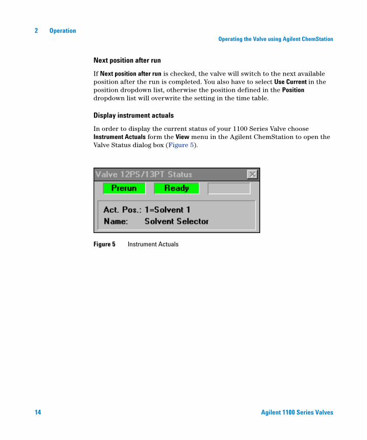
Display instrument actuals
In order to display the current status of your 1100 Series Valve choose Instrument Actuals form the View menu in the Agilent ChemStation to open the Valve Status dialog box (Figure 5).
Figure 5 Instrument Actuals

Agilent 1100 Series Valves 15
Operation 2Handheld Controller functions
Handheld Controller functions
With firmware revision B.03.11 or higher the following valve functions with the Agilent 1100 Series handheld controller G1323B are available. Complete control of an 1100 Series Valve during an LC analysis requires ChemStation Revision A.09.03 or higher.
Switching the Valve
1 From the startup screen of the 1100 Series Handheld Control Module select System (F5)
2 Select Control (F5) and then Valve to open the screen that is displayed in Figure 6. Use the arrow keys (up and down) to switch the valve to the next position.
Valve Synchronization
1 From the startup screen of the 1100 Series Handheld Control Module select System (F5)
2 Select Tests (F3) and Valve to open the Synchronization screen as displayed in Figure 7.
3 Press Synchronize (F7) and select the position for the valve synchronization. Please also read the section “Valve Synchronization" on page 27.
Figure 6 Switching the 1100 Series Valve
16 Agilent 1100 Series Valves
2 OperationHandheld Controller functions
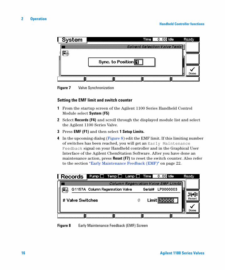
Setting the EMF limit and switch counter
1 From the startup screen of the Agilent 1100 Series Handheld Control Module select System (F5)
2 Select Records (F4) and scroll through the displayed module list and select the Agilent 1100 Series Valve.
3 Press EMF (F1) and then select 1 Setup Limits.
4 In the upcoming dialog (Figure 8) edit the EMF limit. If this limiting number of switches has been reached, you will get an Early Maintenance Feedback signal on your Handheld controller and in the Graphical User Interface of the Agilent ChemStation Software. After you have done an maintenance action, press Reset (F7) to reset the switch counter. Also refer to the section “Early Maintenance Feedback (EMF)" on page 22.
Figure 7 Valve Synchronization
Figure 8 Early Maintenance Feedback (EMF) Screen
17
Agilent 1100 Agilent 1100 Series ValvesOperator’s Manual
Agilent Technologies
3Maintenance, Repair, and Troubleshooting
Maintenance and Repair 18
System Errors and Troubleshooting 24
18 Agilent 1100 Series Valves
3 Maintenance, Repair, and TroubleshootingMaintenance and Repair
Maintenance and Repair
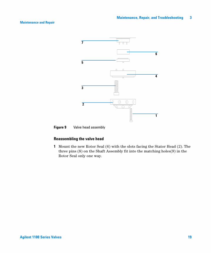
The maintenance of the Agilent 1100 Series Valves includes the exchange of the stator face and the rotor seal. In addition it might be necessary to exchange the stator head, if the threads are worn out or if a fitting is broken and cannot be removed from the stator head. The Valve head assembly is displayed in Figure 9 on page 19 and Figure 10 on page 20. Part numbers of the rebuild kits, rotor seals and stator heads are listed in Table 5 on page 21.
Replacing the stator face and the rotor seal
Disassembling the valve head
1 Use the Hex Key to remove the Stator Screws (1) from the Stator Head (2).
2 Disassemble the Stator Head and Stator Face (5) from the Stator Ring (4). The Stator Face usually remains on the Stator Head.
3 Remove the three Stator Ring Screws (3) and take off the Stator Ring (4).
4 Remove the Rotor Seal(6) from the Valve Body(7). The Rotor Seal is mounted on three pins, and can be pulled off.
CAUTION Always rinse the valve with water after using aqueous buffers or salt solutions to prevent crystal formation which may damage the valve.
Agilent 1100 Series Valves 19
Maintenance, Repair, and Troubleshooting 3Maintenance and Repair
Reassembling the valve head
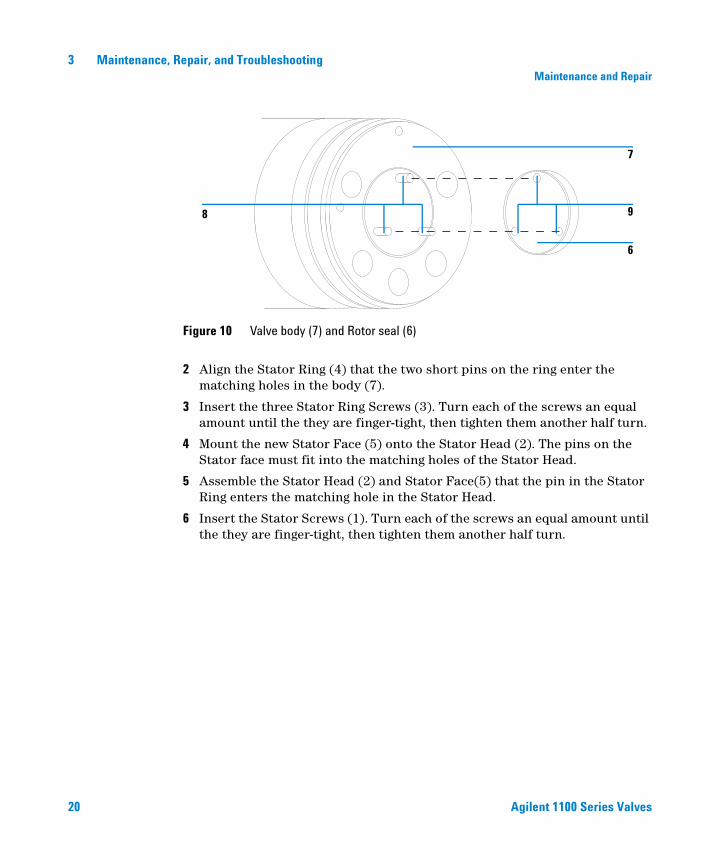
1 Mount the new Rotor Seal (6) with the slots facing the Stator Head (2). The three pins (8) on the Shaft Assembly fit into the matching holes(9) in the Rotor Seal only one way.
Figure 9 Valve head assembly
1
2
3
5
7
4
6
20 Agilent 1100 Series Valves
3 Maintenance, Repair, and TroubleshootingMaintenance and Repair
2 Align the Stator Ring (4) that the two short pins on the ring enter the matching holes in the body (7).
3 Insert the three Stator Ring Screws (3). Turn each of the screws an equal amount until the they are finger-tight, then tighten them another half turn.
4 Mount the new Stator Face (5) onto the Stator Head (2). The pins on the Stator face must fit into the matching holes of the Stator Head.
5 Assemble the Stator Head (2) and Stator Face(5) that the pin in the Stator Ring enters the matching hole in the Stator Head.
6 Insert the Stator Screws (1). Turn each of the screws an equal amount until the they are finger-tight, then tighten them another half turn.
Figure 10 Valve body (7) and Rotor seal (6)
8
6
9
7
Agilent 1100 Series Valves 21
Maintenance, Repair, and Troubleshooting 3Maintenance and Repair
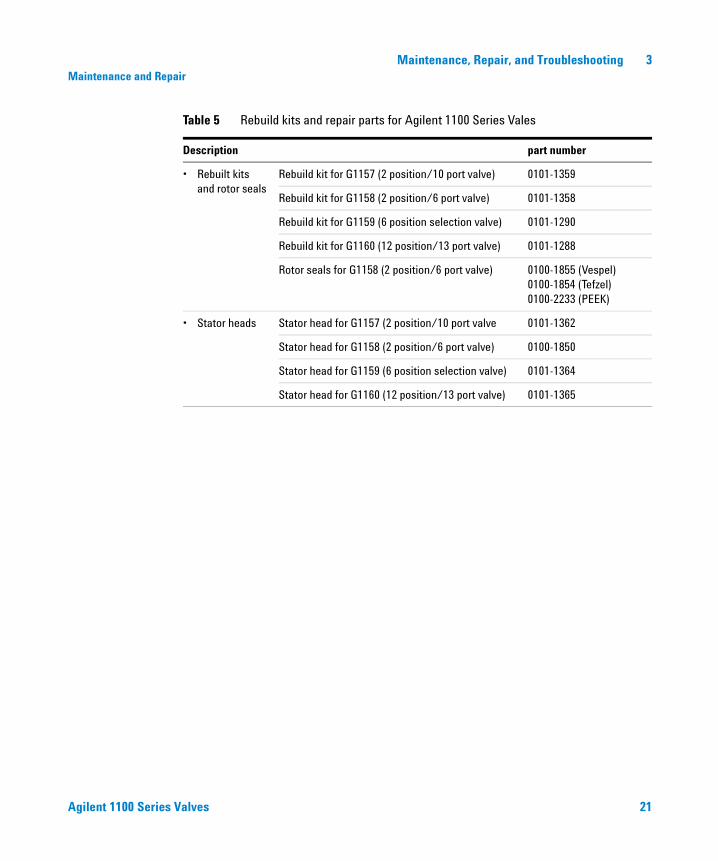
Table 5 Rebuild kits and repair parts for Agilent 1100 Series Vales
Description part number
• Rebuilt kits and rotor seals
Rebuild kit for G1157 (2 position/10 port valve) 0101-1359
Rebuild kit for G1158 (2 position/6 port valve) 0101-1358
Rebuild kit for G1159 (6 position selection valve) 0101-1290
Rebuild kit for G1160 (12 position/13 port valve) 0101-1288
Rotor seals for G1158 (2 position/6 port valve) 0100-1855 (Vespel)0100-1854 (Tefzel)0100-2233 (PEEK)
• Stator heads Stator head for G1157 (2 position/10 port valve 0101-1362
Stator head for G1158 (2 position/6 port valve) 0100-1850
Stator head for G1159 (6 position selection valve) 0101-1364
Stator head for G1160 (12 position/13 port valve) 0101-1365
22 Agilent 1100 Series Valves
3 Maintenance, Repair, and TroubleshootingMaintenance and Repair
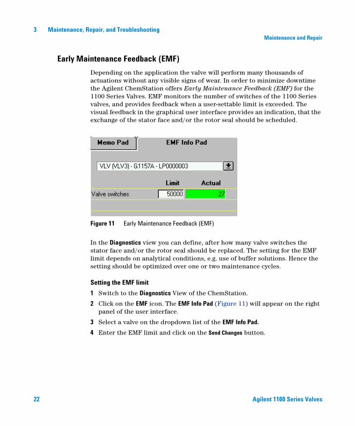
Early Maintenance Feedback (EMF)
Depending on the application the valve will perform many thousands of actuations without any visible signs of wear. In order to minimize downtime the Agilent ChemStation offers Early Maintenance Feedback (EMF) for the 1100 Series Valves. EMF monitors the number of switches of the 1100 Series valves, and provides feedback when a user-settable limit is exceeded. The visual feedback in the graphical user interface provides an indication, that the exchange of the stator face and/or the rotor seal should be scheduled.
In the Diagnostics view you can define, after how many valve switches the stator face and/or the rotor seal should be replaced. The setting for the EMF limit depends on analytical conditions, e.g. use of buffer solutions. Hence the setting should be optimized over one or two maintenance cycles.
Setting the EMF limit
1 Switch to the Diagnostics View of the ChemStation.
2 Click on the EMF icon. The EMF Info Pad (Figure 11) will appear on the right panel of the user interface.
3 Select a valve on the dropdown list of the EMF Info Pad.
4 Enter the EMF limit and click on the Send Changes button.
Figure 11 Early Maintenance Feedback (EMF)
Agilent 1100 Series Valves 23
Maintenance, Repair, and Troubleshooting 3Maintenance and Repair
Resetting the EMF counter
1 Switch to the Diagnostics View of the ChemStation.
2 Select Valve from the Maintenance menu.
3 In the upcoming dialog box click on Reset Counter (see also Figure 16 on page 27).
The procedure to reset the EMF counter with the 1100 Series handheld controller is described on page 16.
24 Agilent 1100 Series Valves
3 Maintenance, Repair, and TroubleshootingSystem Errors and Troubleshooting
System Errors and Troubleshooting
System Errors
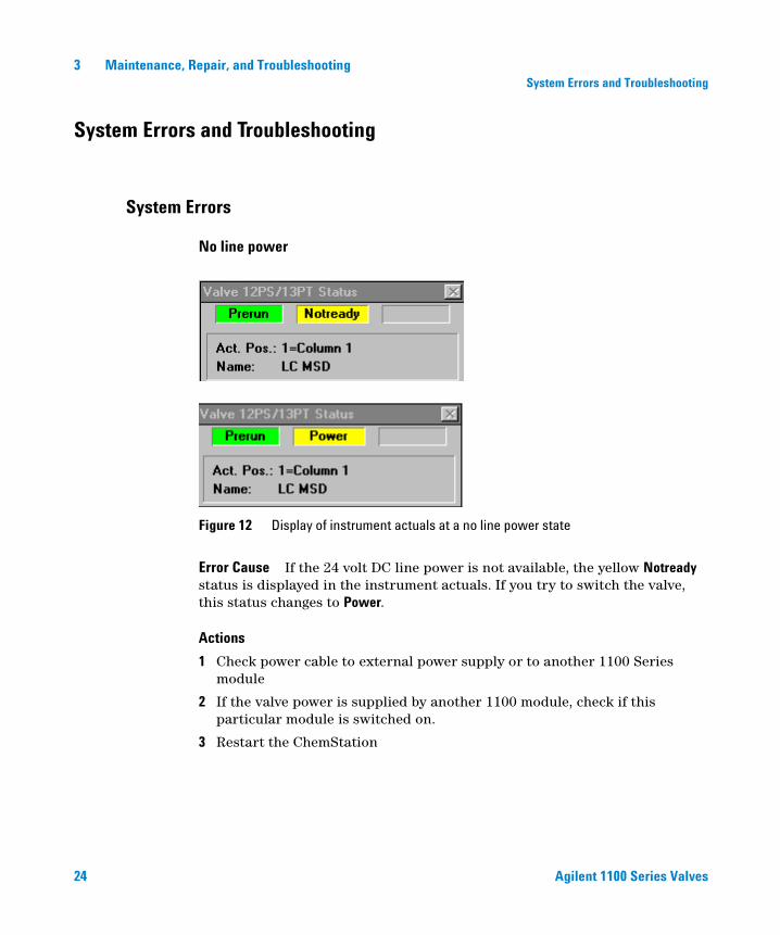
No line power
Error Cause If the 24 volt DC line power is not available, the yellow Notready status is displayed in the instrument actuals. If you try to switch the valve, this status changes to Power.
Actions
1 Check power cable to external power supply or to another 1100 Series module
2 If the valve power is supplied by another 1100 module, check if this particular module is switched on.
3 Restart the ChemStation
Figure 12 Display of instrument actuals at a no line power state
Agilent 1100 Series Valves 25
Maintenance, Repair, and Troubleshooting 3System Errors and Troubleshooting
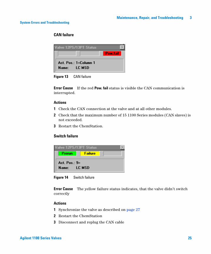
CAN failure
Error Cause If the red Pow. fail status is visible the CAN communication is interrupted.
Actions
1 Check the CAN connection at the valve and at all other modules.
2 Check that the maximum number of 15 1100 Series modules (CAN slaves) is not exceeded.
3 Restart the ChemStation.
Switch failure
Error Cause The yellow failure status indicates, that the valve didn’t switch correctly
Actions
1 Synchronize the valve as described on page 27
2 Restart the ChemStation
3 Disconnect and replug the CAN cable
Figure 13 CAN failure
Figure 14 Switch failure
26 Agilent 1100 Series Valves
3 Maintenance, Repair, and TroubleshootingSystem Errors and Troubleshooting
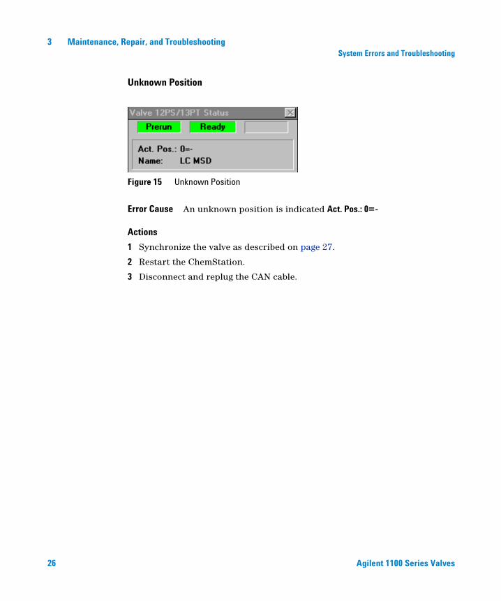
Unknown Position
Error Cause An unknown position is indicated Act. Pos.: 0=-
Actions
1 Synchronize the valve as described on page 27.
2 Restart the ChemStation.
3 Disconnect and replug the CAN cable.
Figure 15 Unknown Position
Agilent 1100 Series Valves 27
Maintenance, Repair, and Troubleshooting 3System Errors and Troubleshooting
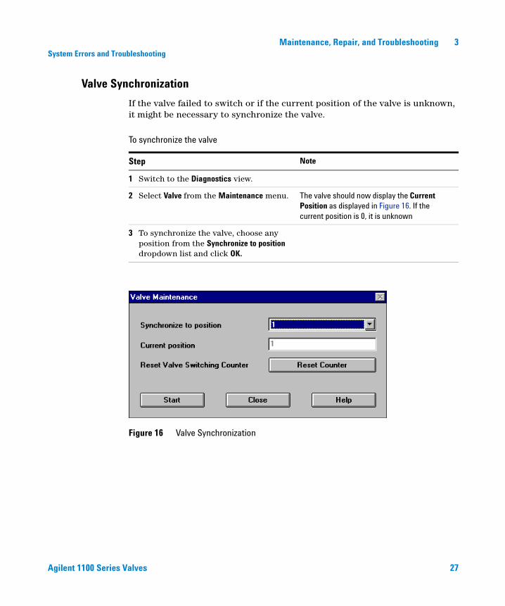
Valve Synchronization
If the valve failed to switch or if the current position of the valve is unknown, it might be necessary to synchronize the valve.
To synchronize the valve
Step Note
1 Switch to the Diagnostics view.
2 Select Valve from the Maintenance menu. The valve should now display the Current Position as displayed in Figure 16. If the current position is 0, it is unknown
3 To synchronize the valve, choose any position from the Synchronize to position dropdown list and click OK.
Figure 16 Valve Synchronization

28 Agilent 1100 Series Valves
3 Maintenance, Repair, and TroubleshootingSystem Errors and Troubleshooting
29
Agilent 1100 Agilent 1100 Series ValvesOperator’s Manual
Agilent Technologies
4Valve Applications
Alternating Column Regeneration 30
Sample enrichment and Sample stripping 34
Column Selection 38
Solvent Selection 40
In this chapter selected applications for the Agilent 1100 Series Valves will be described. This description will contain:
• short description
• flow diagrams
• part numbers of capillaries, fittings and capillary kits
30 Agilent 1100 Series Valves
4 Valve ApplicationsAlternating Column Regeneration
Alternating Column Regeneration
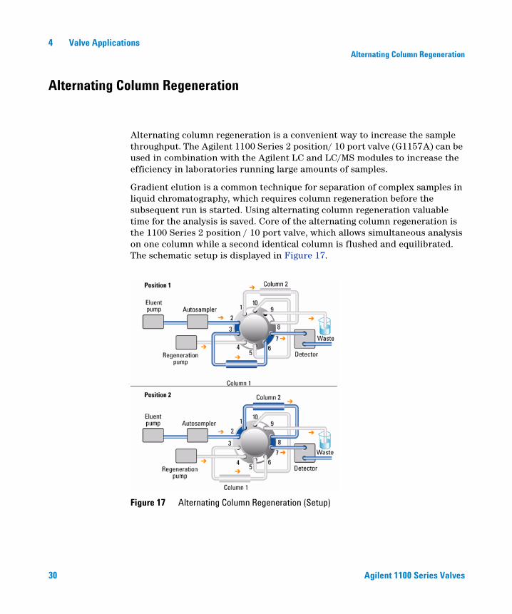
Alternating column regeneration is a convenient way to increase the sample throughput. The Agilent 1100 Series 2 position/ 10 port valve (G1157A) can be used in combination with the Agilent LC and LC/MS modules to increase the efficiency in laboratories running large amounts of samples.
Gradient elution is a common technique for separation of complex samples in liquid chromatography, which requires column regeneration before the subsequent run is started. Using alternating column regeneration valuable time for the analysis is saved. Core of the alternating column regeneration is the 1100 Series 2 position / 10 port valve, which allows simultaneous analysis on one column while a second identical column is flushed and equilibrated. The schematic setup is displayed in Figure 17.
Figure 17 Alternating Column Regeneration (Setup)
Agilent 1100 Series Valves 31
Valve Applications 4Alternating Column Regeneration
If the valve is switched to position 1 the eluent pump delivers the mobile phase through the injection loop of the autosampler into port 2 of the 1100 Series Valve. The sample is separated on column 1 and analyzed by the detector. Simultaneously a second regeneration pump flushes and equilibrates column 2.
After the analysis of the sample is finished on column 1, column 2 is prepared for an immediate injection. The 2 position/ 10 port valve is switched and the sample can be injected and analyzed. While the analysis is running on column 2, column 1 is now regenerated and will be ready to use immediately after the sample run on column 2 is finished.
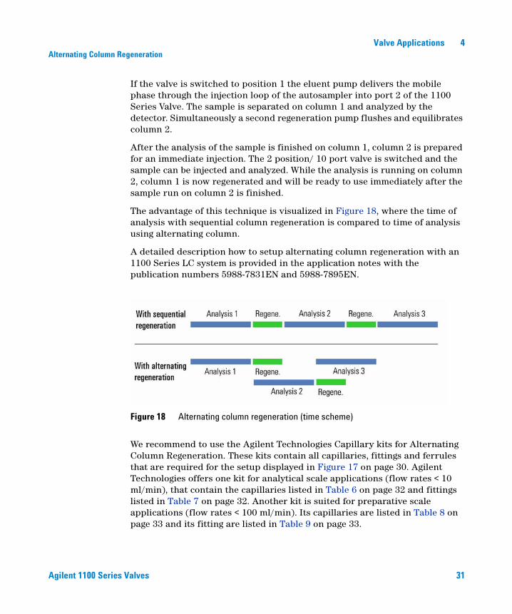
The advantage of this technique is visualized in Figure 18, where the time of analysis with sequential column regeneration is compared to time of analysis using alternating column.
A detailed description how to setup alternating column regeneration with an 1100 Series LC system is provided in the application notes with the publication numbers 5988-7831EN and 5988-7895EN.
We recommend to use the Agilent Technologies Capillary kits for Alternating Column Regeneration. These kits contain all capillaries, fittings and ferrules that are required for the setup displayed in Figure 17 on page 30. Agilent Technologies offers one kit for analytical scale applications (flow rates < 10 ml/min), that contain the capillaries listed in Table 6 on page 32 and fittings listed in Table 7 on page 32. Another kit is suited for preparative scale applications (flow rates < 100 ml/min). Its capillaries are listed in Table 8 on page 33 and its fitting are listed in Table 9 on page 33.
Figure 18 Alternating column regeneration (time scheme)
32 Agilent 1100 Series Valves
4 Valve ApplicationsAlternating Column Regeneration
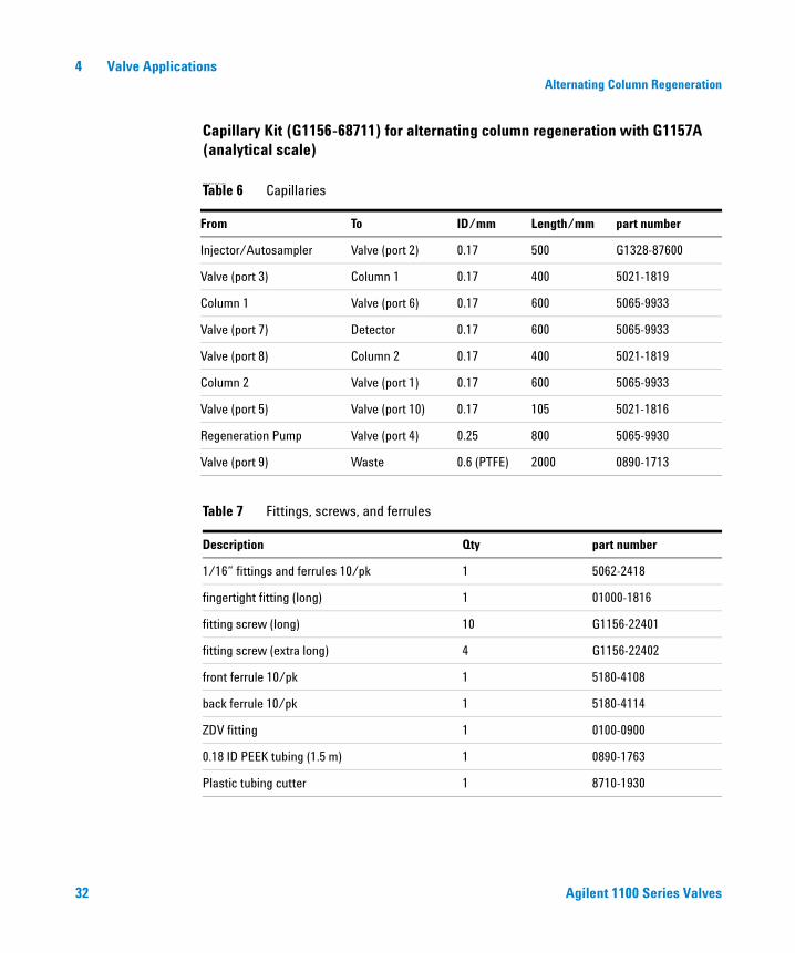
Capillary Kit (G1156-68711) for alternating column regeneration with G1157A (analytical scale)
(Analytical Scale)
Table 6 Capillaries
From To ID/mm Length/mm part number
Injector/Autosampler Valve (port 2) 0.17 500 G1328-87600
Valve (port 3) Column 1 0.17 400 5021-1819
Column 1 Valve (port 6) 0.17 600 5065-9933
Valve (port 7) Detector 0.17 600 5065-9933
Valve (port 8) Column 2 0.17 400 5021-1819
Column 2 Valve (port 1) 0.17 600 5065-9933
Valve (port 5) Valve (port 10) 0.17 105 5021-1816
Regeneration Pump Valve (port 4) 0.25 800 5065-9930
Valve (port 9) Waste 0.6 (PTFE) 2000 0890-1713
Table 7 Fittings, screws, and ferrules
Description Qty part number
1/16” fittings and ferrules 10/pk 1 5062-2418
fingertight fitting (long) 1 01000-1816
fitting screw (long) 10 G1156-22401
fitting screw (extra long) 4 G1156-22402
front ferrule 10/pk 1 5180-4108
back ferrule 10/pk 1 5180-4114
ZDV fitting 1 0100-0900
0.18 ID PEEK tubing (1.5 m) 1 0890-1763
Plastic tubing cutter 1 8710-1930
Agilent 1100 Series Valves 33
Valve Applications 4Alternating Column Regeneration
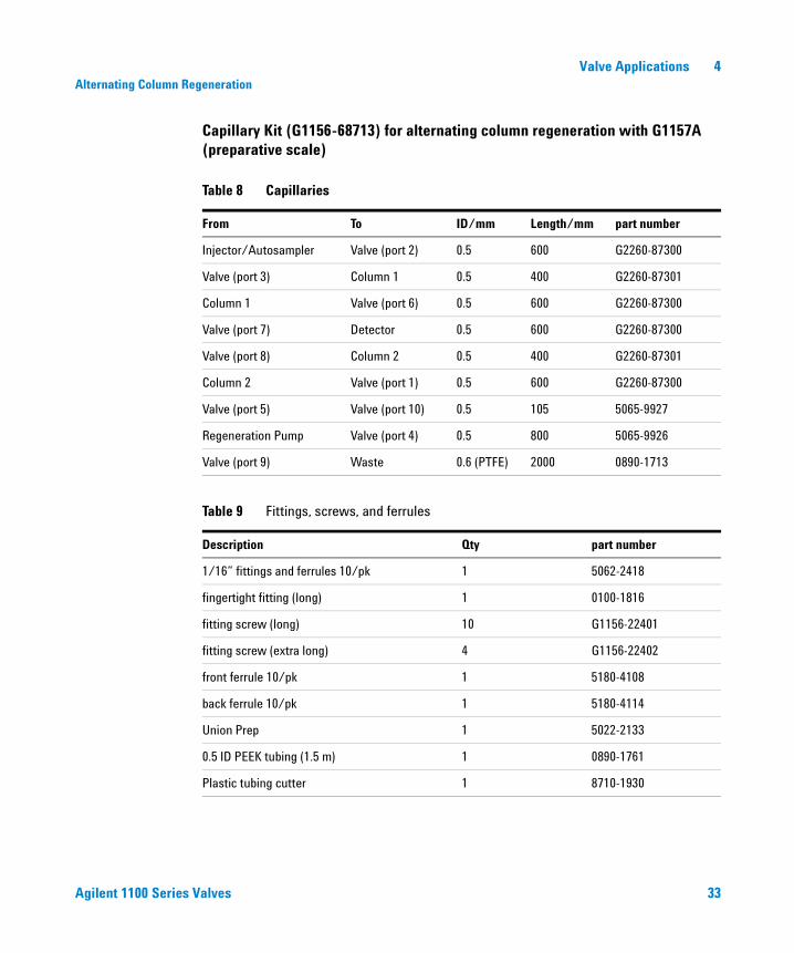
Capillary Kit (G1156-68713) for alternating column regeneration with G1157A (preparative scale)
Table 8 Capillaries
From To ID/mm Length/mm part number
Injector/Autosampler Valve (port 2) 0.5 600 G2260-87300
Valve (port 3) Column 1 0.5 400 G2260-87301
Column 1 Valve (port 6) 0.5 600 G2260-87300
Valve (port 7) Detector 0.5 600 G2260-87300
Valve (port 8) Column 2 0.5 400 G2260-87301
Column 2 Valve (port 1) 0.5 600 G2260-87300
Valve (port 5) Valve (port 10) 0.5 105 5065-9927
Regeneration Pump Valve (port 4) 0.5 800 5065-9926
Valve (port 9) Waste 0.6 (PTFE) 2000 0890-1713
Table 9 Fittings, screws, and ferrules
Description Qty part number
1/16” fittings and ferrules 10/pk 1 5062-2418
fingertight fitting (long) 1 0100-1816
fitting screw (long) 10 G1156-22401
fitting screw (extra long) 4 G1156-22402
front ferrule 10/pk 1 5180-4108
back ferrule 10/pk 1 5180-4114
Union Prep 1 5022-2133
0.5 ID PEEK tubing (1.5 m) 1 0890-1761
Plastic tubing cutter 1 8710-1930
34 Agilent 1100 Series Valves
4 Valve ApplicationsSample enrichment and Sample stripping
Sample enrichment and Sample stripping
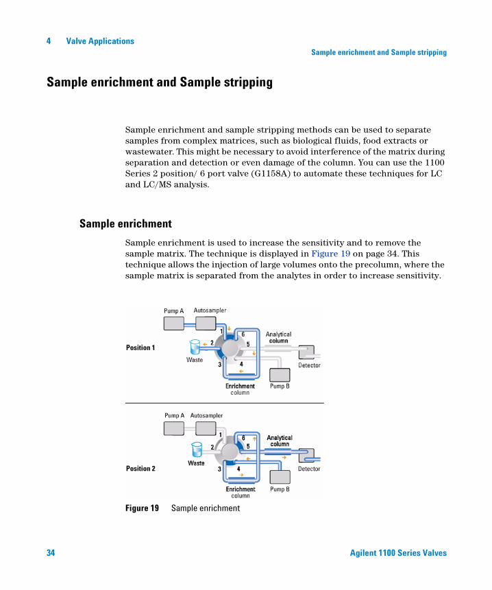
Sample enrichment and sample stripping methods can be used to separate samples from complex matrices, such as biological fluids, food extracts or wastewater. This might be necessary to avoid interference of the matrix during separation and detection or even damage of the column. You can use the 1100 Series 2 position/ 6 port valve (G1158A) to automate these techniques for LC and LC/MS analysis.
Sample enrichment
Sample enrichment is used to increase the sensitivity and to remove the sample matrix. The technique is displayed in Figure 19 on page 34. This technique allows the injection of large volumes onto the precolumn, where the sample matrix is separated from the analytes in order to increase sensitivity.
Figure 19 Sample enrichment
Agilent 1100 Series Valves 35
Valve Applications 4Sample enrichment and Sample stripping
For the sample enrichment phase the valve is switched to position 1. The eluent Pump A transfers the injected sample onto the enrichment column. The sample is retained and enriched on this column, whereas the sample matrix is flushed into the waste. At the same time the second eluent pump B is equilibrating the analytical column.
After the valve is switched to position 2 pump B is backflushing the sample on the analytical column for separation and subsequent detection by LC/MS or optical detectors.
Agilent Technologies offers capillary kit for sample enrichment and sample stripping. The content is listed in Table 10 on page 36 and Table 11 on page 37.
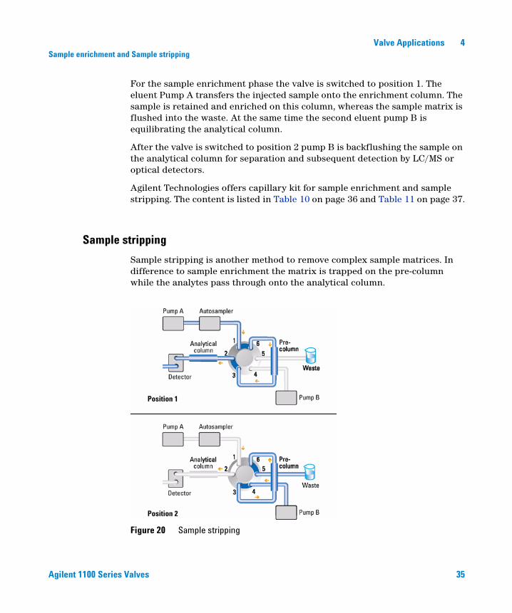
Sample stripping
Sample stripping is another method to remove complex sample matrices. In difference to sample enrichment the matrix is trapped on the pre-column while the analytes pass through onto the analytical column.
Figure 20 Sample stripping
36 Agilent 1100 Series Valves
4 Valve ApplicationsSample enrichment and Sample stripping
Figure 20 on page 35 illustrates how the Agilent 1100 Series 2 position/ 6 port valve can be used for sample stripping. In valve position 1 Pump A transfers the complete sample matrix onto the pre-column 1, where the matrix is trapped while the analytes are eluted and flushed to column 2 for analysis. Then the valve switches to position 2. Now pump B backflushes the matrix to the waste, while pump A continues to deliver solvent to the analytical column, where the the analytes are separated and analyzed.
Agilent Technologies offers a capillary kit for sample enrichment and stripping as displayed in Table 10 on page 36 and Table 11 on page 37.
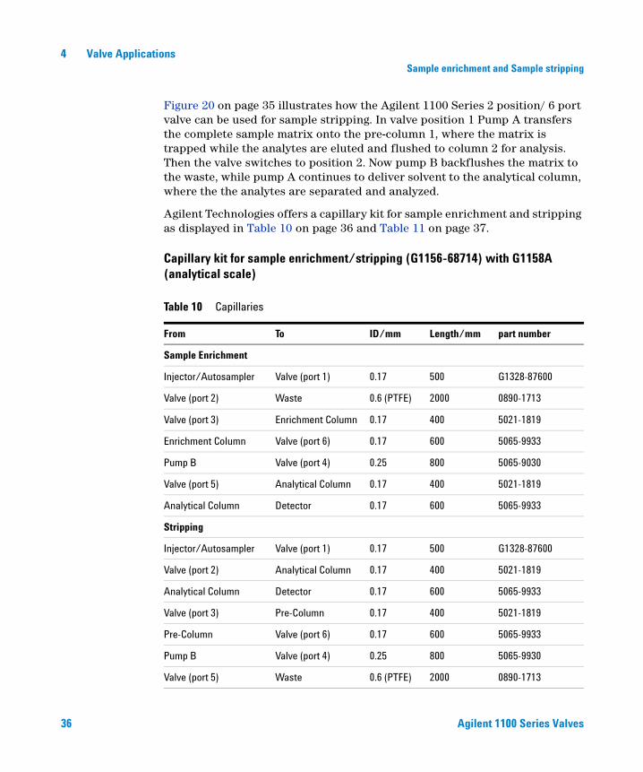
Capillary kit for sample enrichment/stripping (G1156-68714) with G1158A (analytical scale)
Table 10 Capillaries
From To ID/mm Length/mm part number
Sample Enrichment
Injector/Autosampler Valve (port 1) 0.17 500 G1328-87600
Valve (port 2) Waste 0.6 (PTFE) 2000 0890-1713
Valve (port 3) Enrichment Column 0.17 400 5021-1819
Enrichment Column Valve (port 6) 0.17 600 5065-9933
Pump B Valve (port 4) 0.25 800 5065-9030
Valve (port 5) Analytical Column 0.17 400 5021-1819
Analytical Column Detector 0.17 600 5065-9933
Stripping
Injector/Autosampler Valve (port 1) 0.17 500 G1328-87600
Valve (port 2) Analytical Column 0.17 400 5021-1819
Analytical Column Detector 0.17 600 5065-9933
Valve (port 3) Pre-Column 0.17 400 5021-1819
Pre-Column Valve (port 6) 0.17 600 5065-9933
Pump B Valve (port 4) 0.25 800 5065-9930
Valve (port 5) Waste 0.6 (PTFE) 2000 0890-1713
Agilent 1100 Series Valves 37
Valve Applications 4Sample enrichment and Sample stripping
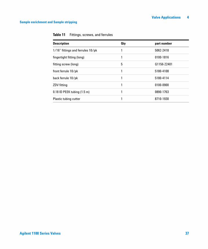
Table 11 Fittings, screws, and ferrules
Description Qty part number
1/16” fittings and ferrules 10/pk 1 5062-2418
fingertight fitting (long) 1 0100-1816
fitting screw (long) 5 G1156-22401
front ferrule 10/pk 1 5180-4108
back ferrule 10/pk 1 5180-4114
ZDV fitting 1 0100-0900
0.18 ID PEEK tubing (1.5 m) 1 0890-1763
Plastic tubing cutter 1 8710-1930
38 Agilent 1100 Series Valves
4 Valve ApplicationsColumn Selection
Column Selection
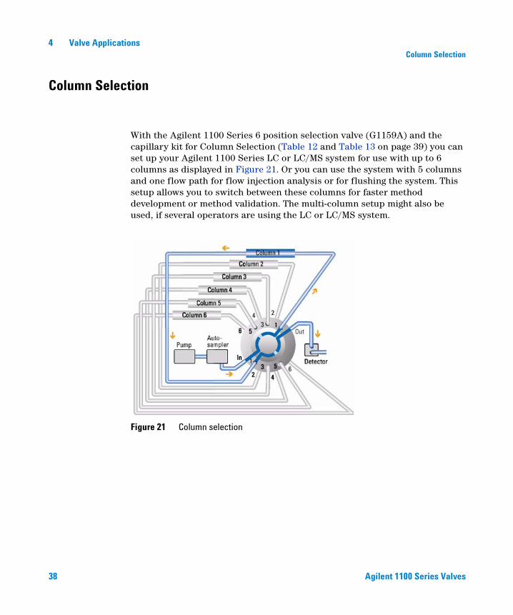
With the Agilent 1100 Series 6 position selection valve (G1159A) and the capillary kit for Column Selection (Table 12 and Table 13 on page 39) you can set up your Agilent 1100 Series LC or LC/MS system for use with up to 6 columns as displayed in Figure 21. Or you can use the system with 5 columns and one flow path for flow injection analysis or for flushing the system. This setup allows you to switch between these columns for faster method development or method validation. The multi-column setup might also be used, if several operators are using the LC or LC/MS system.
Figure 21 Column selection
Agilent 1100 Series Valves 39
Valve Applications 4Column Selection
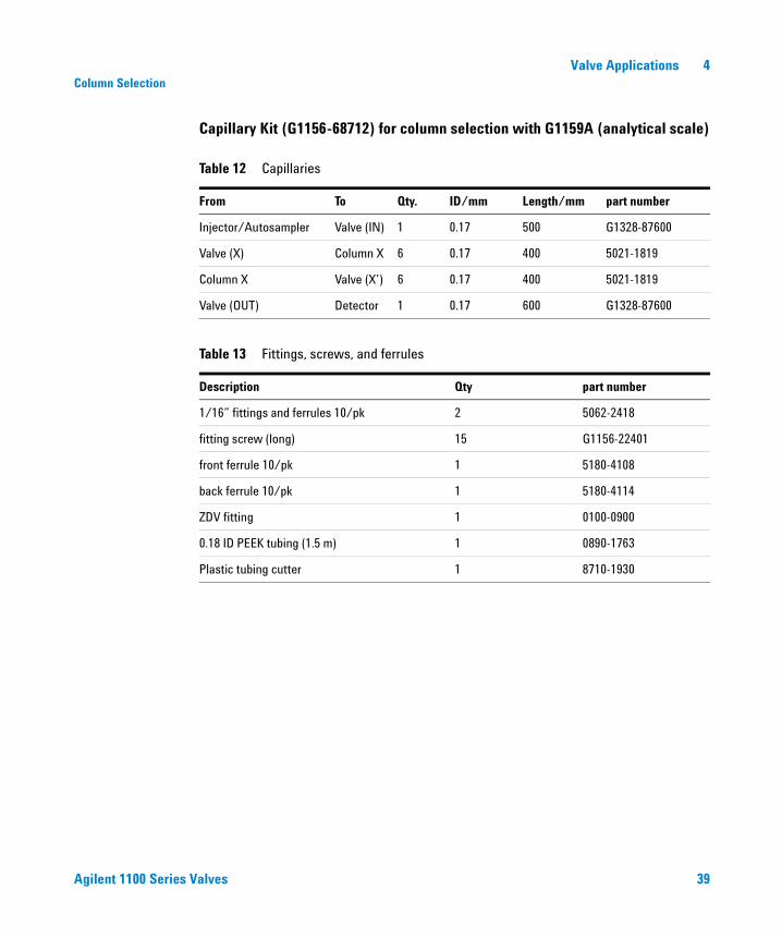
Capillary Kit (G1156-68712) for column selection with G1159A (analytical scale)
Table 12 Capillaries
From To Qty. ID/mm Length/mm part number
Injector/Autosampler Valve (IN) 1 0.17 500 G1328-87600
Valve (X) Column X 6 0.17 400 5021-1819
Column X Valve (X’) 6 0.17 400 5021-1819
Valve (OUT) Detector 1 0.17 600 G1328-87600
Table 13 Fittings, screws, and ferrules
Description Qty part number
1/16” fittings and ferrules 10/pk 2 5062-2418
fitting screw (long) 15 G1156-22401
front ferrule 10/pk 1 5180-4108
back ferrule 10/pk 1 5180-4114
ZDV fitting 1 0100-0900
0.18 ID PEEK tubing (1.5 m) 1 0890-1763
Plastic tubing cutter 1 8710-1930
40 Agilent 1100 Series Valves
4 Valve ApplicationsSolvent Selection
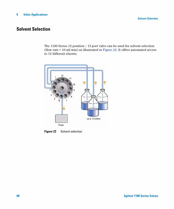
Solvent Selection
The 1100 Series 12 position / 13 port valve can be used for solvent selection (flow rate < 10 ml/min) as illustrated in Figure 22. It offers automated access to 12 different eluents.
Figure 22 Solvent selection
Agilent 1100 Series Valves 41
Valve Applications 4Solvent Selection
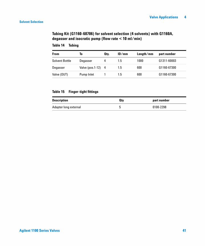
Tubing Kit (G1160-68706) for solvent selection (4 solvents) with G1160A, degasser and isocratic pump (flow rate < 10 ml/min)
Table 14 Tubing
From To Qty. ID/mm Length/mm part number
Solvent Bottle Degasser 4 1.5 1000 G1311-60003
Degasser Valve (pos.1-12) 4 1.5 600 G1160-67300
Valve (OUT) Pump Inlet 1 1.5 600 G1160-67300
Table 15 Finger-tight fittings
Description Qty part number
Adapter long external 5 0100-2298

42 Agilent 1100 Series Valves
4 Valve ApplicationsSolvent Selection
43
Agilent 1100 Agilent 1100 Series ValvesOperator’s Manual
Agilent Technologies
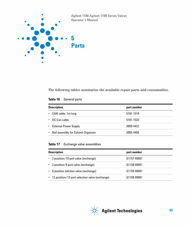
5Parts
The following tables summarize the available repair parts and consumables.
Table 16 General parts
Description part number
• CAN cable, 1m long 5181-1519
• DC-Can cable 5181-1533
• External Power Supply 0950-4422
• Rail assembly for Column Organizer 5065-4450
Table 17 Exchange valve assemblies
Description part number
• 2 position/10 port valve (exchange) G1157-69001
• 2 position/6 port valve (exchange) G1158-69001
• 6 position selction valve (exchange) G1159-69001
• 12 position/13 port selection valve (exchange) G1160-69001
44 Agilent 1100 Series Valves
5 Parts
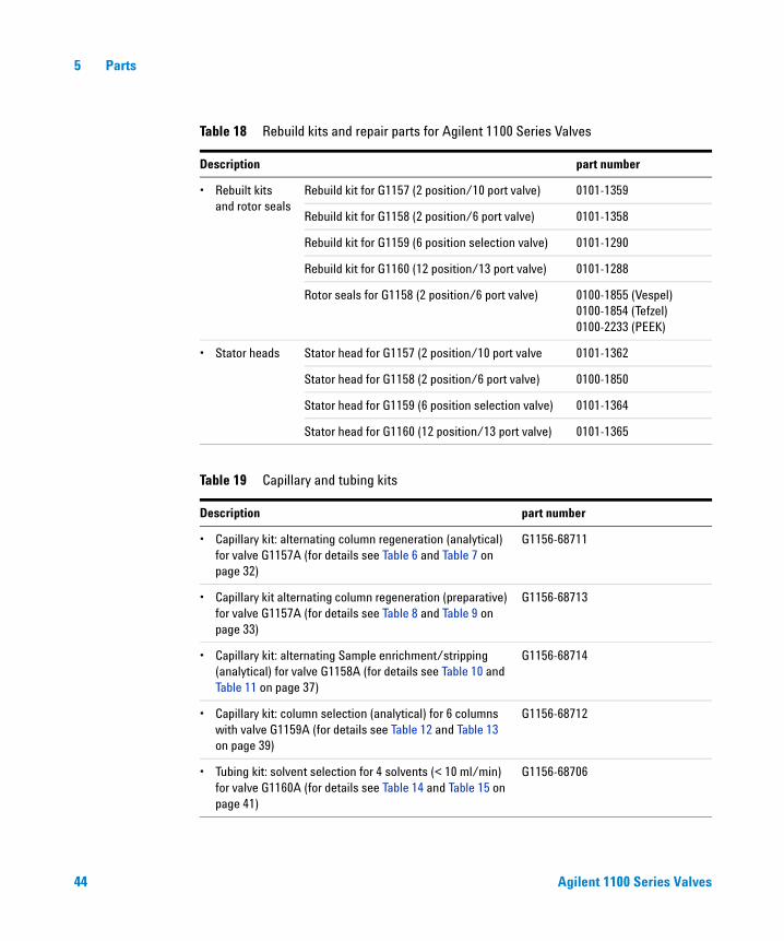
Table 18 Rebuild kits and repair parts for Agilent 1100 Series Valves
Description part number
• Rebuilt kits and rotor seals
Rebuild kit for G1157 (2 position/10 port valve) 0101-1359
Rebuild kit for G1158 (2 position/6 port valve) 0101-1358
Rebuild kit for G1159 (6 position selection valve) 0101-1290
Rebuild kit for G1160 (12 position/13 port valve) 0101-1288
Rotor seals for G1158 (2 position/6 port valve) 0100-1855 (Vespel)0100-1854 (Tefzel)0100-2233 (PEEK)
• Stator heads Stator head for G1157 (2 position/10 port valve 0101-1362
Stator head for G1158 (2 position/6 port valve) 0100-1850
Stator head for G1159 (6 position selection valve) 0101-1364
Stator head for G1160 (12 position/13 port valve) 0101-1365
Table 19 Capillary and tubing kits
Description part number
• Capillary kit: alternating column regeneration (analytical) for valve G1157A (for details see Table 6 and Table 7 on page 32)
G1156-68711
• Capillary kit alternating column regeneration (preparative) for valve G1157A (for details see Table 8 and Table 9 on page 33)
G1156-68713
• Capillary kit: alternating Sample enrichment/stripping (analytical) for valve G1158A (for details see Table 10 and Table 11 on page 37)
G1156-68714
• Capillary kit: column selection (analytical) for 6 columns with valve G1159A (for details see Table 12 and Table 13 on page 39)
G1156-68712
• Tubing kit: solvent selection for 4 solvents (< 10 ml/min) for valve G1160A (for details see Table 14 and Table 15 on page 41)
G1156-68706
Agilent 1100 Series Valves 45
Parts 5
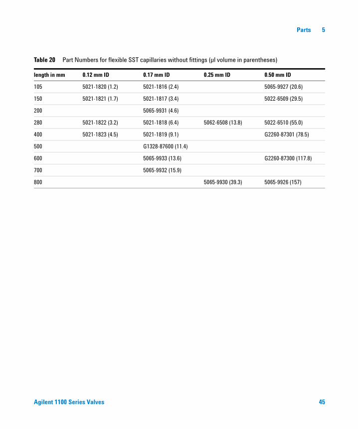
Table 20 Part Numbers for flexible SST capillaries without fittings (µl volume in parentheses)
length in mm 0.12 mm ID 0.17 mm ID 0.25 mm ID 0.50 mm ID
105 5021-1820 (1.2) 5021-1816 (2.4) 5065-9927 (20.6)
150 5021-1821 (1.7) 5021-1817 (3.4) 5022-6509 (29.5)
200 5065-9931 (4.6)
280 5021-1822 (3.2) 5021-1818 (6.4) 5062-6508 (13.8) 5022-6510 (55.0)
400 5021-1823 (4.5) 5021-1819 (9.1) G2260-87301 (78.5)
500 G1328-87600 (11.4)
600 5065-9933 (13.6) G2260-87300 (117.8)
700 5065-9932 (15.9)
800 5065-9930 (39.3) 5065-9926 (157)

46 Agilent 1100 Series Valves
5 Parts
47
Agilent 1100 Agilent 1100 Series ValvesOperator’s Manual
Agilent Technologies
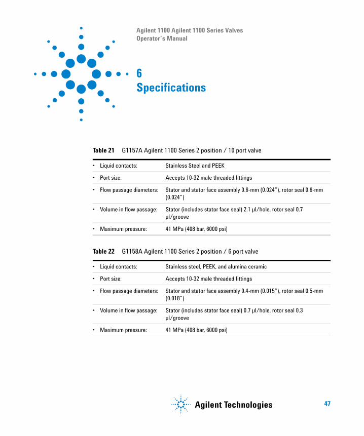
6Specifications
Table 21 G1157A Agilent 1100 Series 2 position / 10 port valve
• Liquid contacts: Stainless Steel and PEEK
• Port size: Accepts 10-32 male threaded fittings
• Flow passage diameters: Stator and stator face assembly 0.6-mm (0.024”), rotor seal 0.6-mm (0.024”)
• Volume in flow passage: Stator (includes stator face seal) 2.1 µl/hole, rotor seal 0.7 µl/groove
• Maximum pressure: 41 MPa (408 bar, 6000 psi)
Table 22 G1158A Agilent 1100 Series 2 position / 6 port valve
• Liquid contacts: Stainless steel, PEEK, and alumina ceramic
• Port size: Accepts 10-32 male threaded fittings
• Flow passage diameters: Stator and stator face assembly 0.4-mm (0.015”), rotor seal 0.5-mm (0.018”)
• Volume in flow passage: Stator (includes stator face seal) 0.7 µl/hole, rotor seal 0.3 µl/groove
• Maximum pressure: 41 MPa (408 bar, 6000 psi)
48 Agilent 1100 Series Valves
6 Specifications
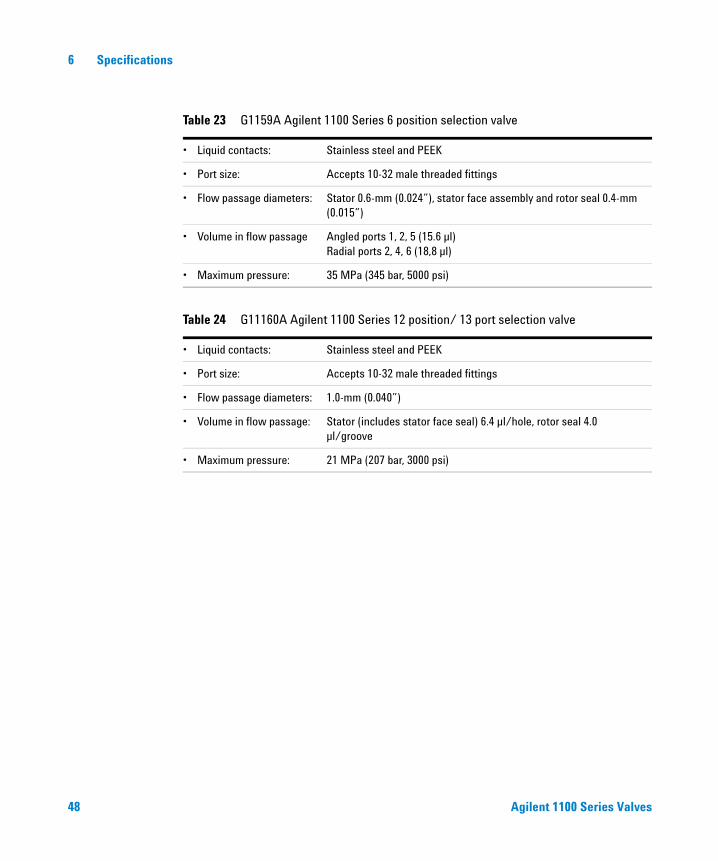
Table 23 G1159A Agilent 1100 Series 6 position selection valve
• Liquid contacts: Stainless steel and PEEK
• Port size: Accepts 10-32 male threaded fittings
• Flow passage diameters: Stator 0.6-mm (0.024”), stator face assembly and rotor seal 0.4-mm (0.015”)
• Volume in flow passage Angled ports 1, 2, 5 (15.6 µl)Radial ports 2, 4, 6 (18,8 µl)
• Maximum pressure: 35 MPa (345 bar, 5000 psi)
Table 24 G11160A Agilent 1100 Series 12 position/ 13 port selection valve
• Liquid contacts: Stainless steel and PEEK
• Port size: Accepts 10-32 male threaded fittings
• Flow passage diameters: 1.0-mm (0.040”)
• Volume in flow passage: Stator (includes stator face seal) 6.4 µl/hole, rotor seal 4.0 µl/groove
• Maximum pressure: 21 MPa (207 bar, 3000 psi)

Agilent 1100 Series Valves 49
Index
Aaccessory kit, 3Agilent ChemStation, 8, 12alternating column regeneration, 30
analytical scale, 32preparative scale, 33
analytical scalealternating column regeneration, 32column selection, 39sample enrichment, 36
CCAN connection, 6CAN failure, 25capillary kits, 44column organizer, 5, 6column selection, 38
analytical scale, 39configuration, software, 8consumables, 43crystal formation, 18
DDC-CAN Cable, 7delivery checklist, 3diagnostics, 22
Eearly maintenance feedback, 16early maintenance feedback (EMF), 22EMF counter, 23EMF info pad, 22EMF limit, 16, 22
Ffinger-tight fittings, 41fittings, 41flow injection analysis, 38flushing, 38
Ggradient elution, 30
Hhandheld controller, 15
Llarge volumes, 34
Mmethod development, 38method validation, 38multi-column setup, 38
Nnotready, 24
Pposition, 12, 13position, unknown, 26pow. fail status, 25power supply, external, 7preparative scale
alternating column regeneration, 33
Rrebuild kit, 18, 44repair parts, 21, 44rotor seal, 18
Ssample enrichment, 34
analytical scale, 36sample matrices
removal, 35sample matrix
removal, 34sample stripping, 35sample throughput, 30selection valve, 38sensitivity, 34setup valve, 12site requirements, 2solvent selection, 40
tubing kit, 41specifications, 47stator face, 18stator head, 18stator ring, 18switch failure, 25switching the valve, 15synchronization, 15, 27system errors, 24
Ttime table, 13troubleshooting, 24tubing kit, 41, 44
50 Agilent 1100 Series Valves
Index
Uunknown position, 26
Vvalve assemblies, 43valve configuration, 9valve head, 18valve name, 13valve parameters, 12valve synchronization, 27

Agilent Technologies
��������������������������G1156-90000
In This Book
This operators manual describes common applications as well as installation, operation and maintenance of the following Agilent 1100 series valves:
• G1157A Agilent 1100 Series 2 Position/10 Port Valve
• G1158A Agilent 1100 Series 2 Position/ 6 Port Valve
• G1159A Agilent 1100 Series 6 Position Selection Valve
• G1160A Agilent 1100 Series 12 Position/13 Port Selection Valve
In additon parts and specifications of these valves are listed.