Embed Size (px)
Citation preview

8/4/2019 Agila Owner's Manual - August 2009
http://slidepdf.com/reader/full/agila-owners-manual-august-2009 1/137
0 - VAUXHALL Agila
VAUXHALL Agila
Owner’s ManualModel Year 2010Edition: August 2009
TS 1669-A-10
8/4/2019 Agila Owner's Manual - August 2009
http://slidepdf.com/reader/full/agila-owners-manual-august-2009 2/137
Introduction ....................................
In brief ............................................
Keys, doors and windows ............ 1
Seats, restraints ........................... 2
Storage ........................................ 4
Instruments and controls .......... ... 4
Lighting ........................................ 6
Infotainment system ..................... 6
Climate control ............................. 7
Driving and operating ................... 8
Vehicle care ................................. 9
Service and maintenance .......... 12
Technical data ........................... 12
Customer information ................ 13
Index .......................................... 13
Contents
8/4/2019 Agila Owner's Manual - August 2009
http://slidepdf.com/reader/full/agila-owners-manual-august-2009 3/137
2 Introduction
Introduction
8/4/2019 Agila Owner's Manual - August 2009
http://slidepdf.com/reader/full/agila-owners-manual-august-2009 4/137
Introduction
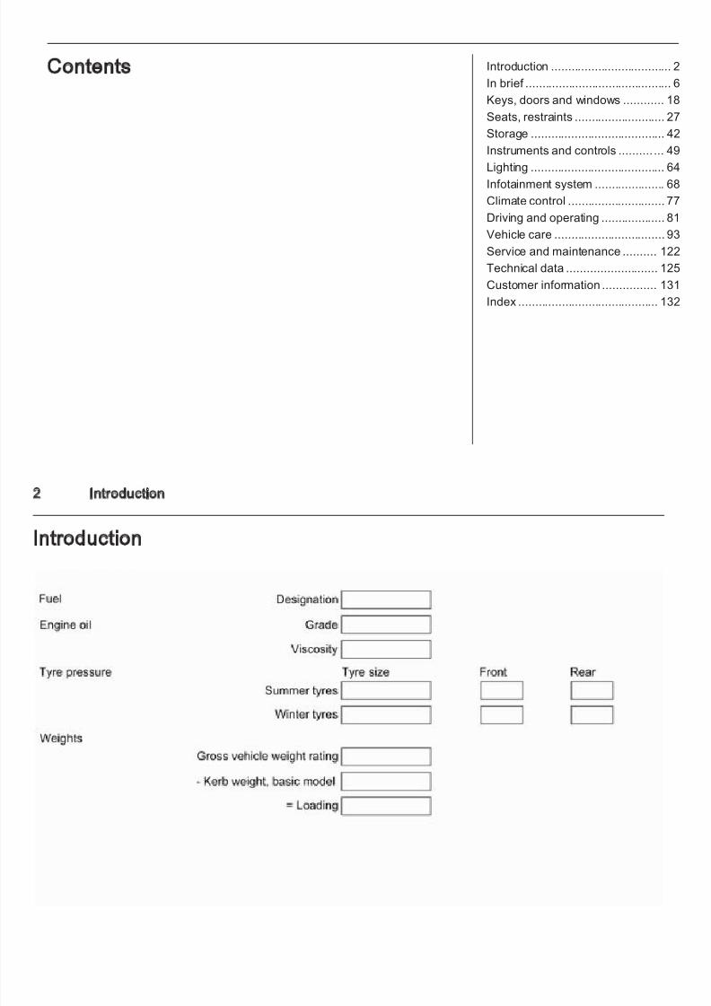
Vehicle specific data
Please enter your vehicle's data onthe previous page to keep it easilyaccessible. This information is
available under the sections "Serviceand maintenance" and "Technicaldata" as well as on the identificationplate.
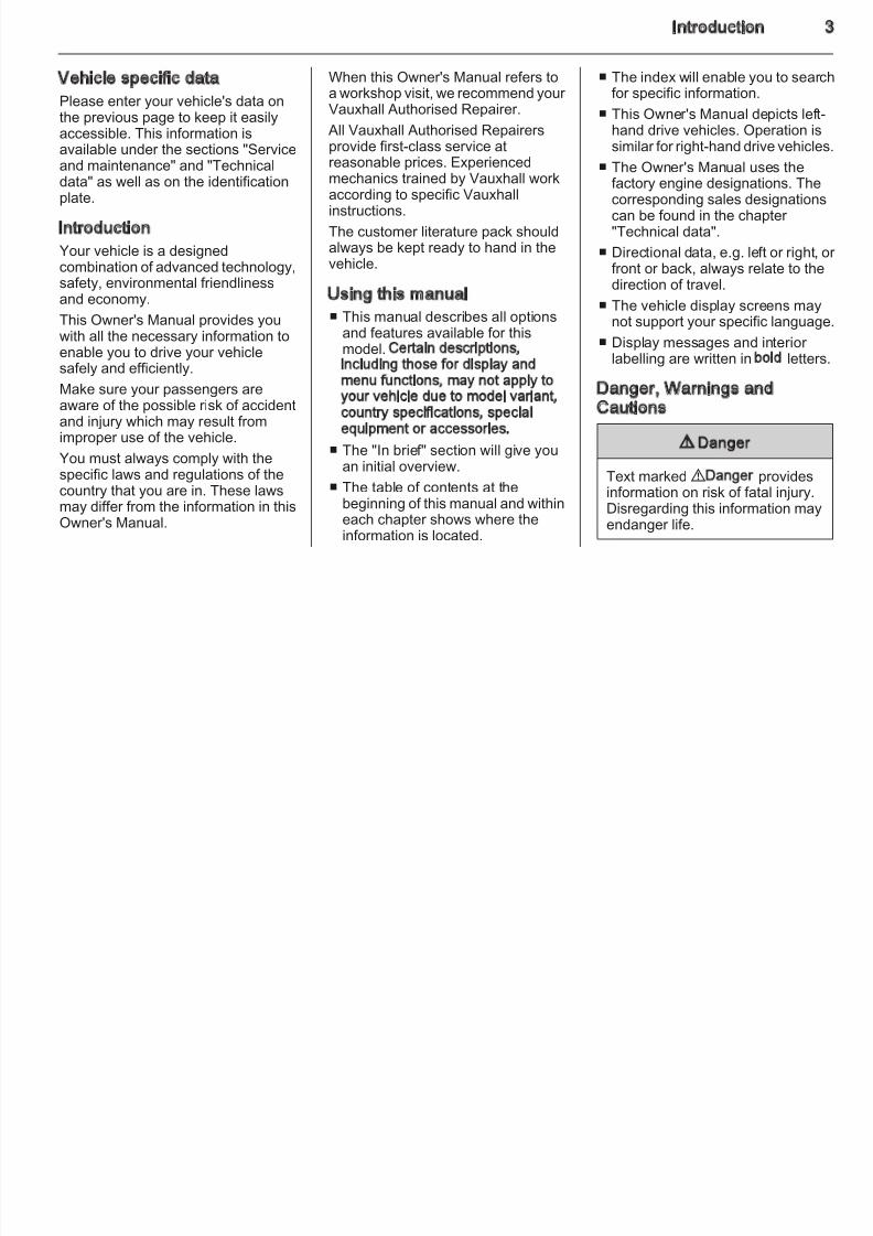
Introduction
Your vehicle is a designedcombination of advanced technology,safety, environmental friendliness
and economy.This Owner's Manual provides youwith all the necessary information toenable you to drive your vehiclesafely and efficiently.
Make sure your passengers areaware of the possible risk of accidentand injur y which may r esult fromimproper use of the vehicle.
You must always comply with thespecific laws and regulations of thecountry that you are in. These lawsmay differ from the information in thisOwner's Manual.
When this Owner's Manual refers toa workshop visit, we recommend your Vauxhall Authorised Repairer.
All Vauxhall Authorised Repairers
provide first-class service atreasonable prices. Experiencedmechanics trained by Vauxhall workaccording to specific Vauxhallinstructions.
The customer literature pack shouldalways be kept ready to hand in thevehicle.
Using this manual
■ This manual describes all optionsand features available for thismodel. Certain descriptions,including those for display andmenu functions, may not apply toyour vehicle due to model variant,country specifications, specialequipment or accessories.
■ The "In brief" section will give youan initial overview.
■ The table of contents at thebeginning of this manual and withineach chapter shows where theinformation is located.
■ The index will enable you to searcfor specific information.
■ This Owner's Manual depicts left-hand drive vehicles. Operation is
similar for right-hand drive vehicles■ The Owner's Manual uses the
factory engine designations. Thecorresponding sales designationscan be found in the chapter "Technical data".
■ Directional data, e.g. left or right, ofront or back, always relate to thedirection of travel.
■ The vehicle display screens maynot support your specific language
■ Display messages and interior labelling are written in bold letters
Danger, Warnings andCautions
9 Danger
Text marked 9 Danger providesinformation on risk of fatal injury.Disregarding this information mayendanger life.
8/4/2019 Agila Owner's Manual - August 2009
http://slidepdf.com/reader/full/agila-owners-manual-august-2009 5/137
4 Introduction
9 Warning
Text marked 9 Warning providesinformation on risk of accident or
injury. Disregarding thisinformation may lead to injury.
Caution
Text marked Caution providesinformation on possible damage tothe vehicle. Disregarding thisinformation may lead to vehicle
damage.
Symbols
Page references are indicated with3. 3 means "see page".
Thank you for choosing a Vauxhall.
We wish you many hours of pleasurable driving.
Your Vauxhall Team
8/4/2019 Agila Owner's Manual - August 2009
http://slidepdf.com/reader/full/agila-owners-manual-august-2009 6/137
Introduction
8/4/2019 Agila Owner's Manual - August 2009
http://slidepdf.com/reader/full/agila-owners-manual-august-2009 7/137
6 In brief
In brief
Initial drive information
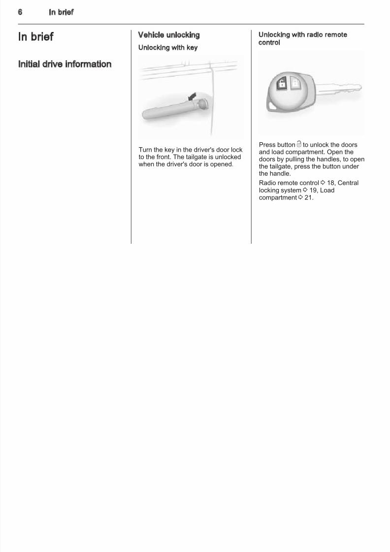
Vehicle unlocking
Unlocking with key
Turn the key in the driver's door lockto the front. The tailgate is unlockedwhen the driver's door is opened.
Unlocking with radio remotecontrol
Press button c to unlock the doorsand load compartment. Open thedoors by pulling the handles, to openthe tailgate, press the button under the handle.
Radio remote control 3 18, Centrallocking system 3 19, Loadcompartment 3 21.
8/4/2019 Agila Owner's Manual - August 2009
http://slidepdf.com/reader/full/agila-owners-manual-august-2009 8/137
In brief
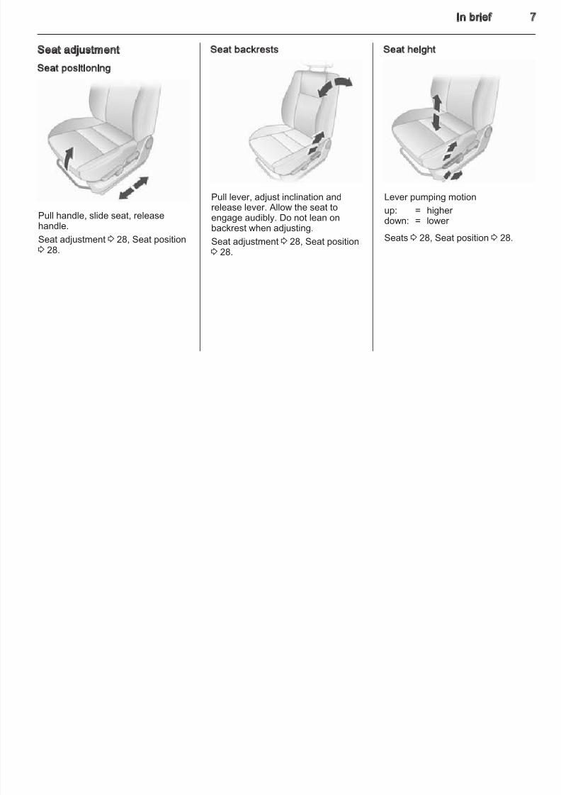
Seat adjustment
Seat positioning
Pull handle, slide seat, releasehandle.
Seat adjustment 3 28, Seat position3 28.
Seat backrests
Pull lever, adjust inclination andrelease lever. Allow the seat toengage audibly. Do not lean onbackrest when adjusting.
Seat adjustment 3 28, Seat position3 28.
Seat height
Lever pumping motionup: = higher down: = lower
Seats 3 28, Seat position 3 28.
8/4/2019 Agila Owner's Manual - August 2009
http://slidepdf.com/reader/full/agila-owners-manual-august-2009 9/137
8 In brief
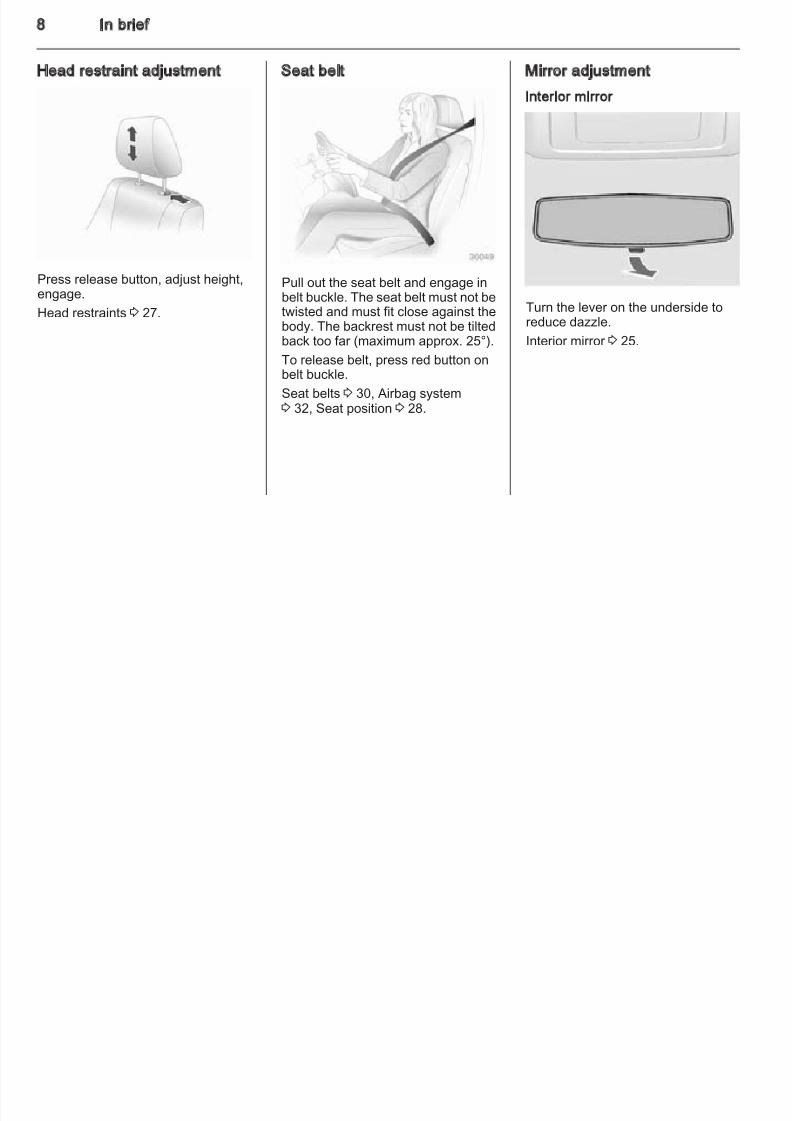
Head restraint adjustment
Press release button, adjust height,engage.
Head restraints 3 27.
Seat belt
Pull out the seat belt and engage inbelt buckle. The seat belt must not betwisted and must fit close against thebody. The backrest must not be tiltedback too far (maximum approx. 25°).
To release belt, press red button onbelt buckle.
Seat belts 3 30, Airbag system3 32, Seat position 3 28.
Mirror adjustment
Interior mirror
Turn the lever on the underside toreduce dazzle.
Interior mirror 3 25.
8/4/2019 Agila Owner's Manual - August 2009
http://slidepdf.com/reader/full/agila-owners-manual-august-2009 10/137
In brief
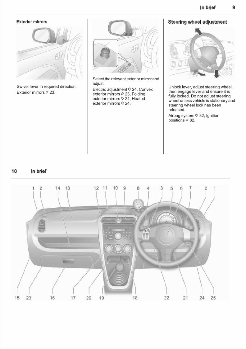
Exterior mirrors
Swivel lever in required direction.Exterior mirrors 3 23.
Select the relevant exterior mirror andadjust.
Electric adjustment 3 24, Convexexterior mirrors 3 23, Foldingexterior mirrors 3 24, Heatedexterior mirrors 3 24.
Steering wheel adjustment
Unlock lever, adjust steering wheel,then engage lever and ensure it isfully locked. Do not adjust steeringwheel unless vehicle is stationary ansteering wheel lock has beenreleased.
Airbag system 3 32, Ignitionpositions 3 82.
8/4/2019 Agila Owner's Manual - August 2009
http://slidepdf.com/reader/full/agila-owners-manual-august-2009 11/137
10 In brief
8/4/2019 Agila Owner's Manual - August 2009
http://slidepdf.com/reader/full/agila-owners-manual-august-2009 12/137
In brief 1
Instrument panel overview
1 Side air vents ....................... 79
2 Door window defroster vents .................................... 79
3 Remote control for infotainment system ............. 49
4 Turn signals, headlightflash, low beam and highbeam .................................... 66Rear fog light ........................ 66
5 Instruments .......................... 53
6 Driver airbag ........................ 33
Horn ..................................... 507 Windscreen wiper,
windscreen washer system .................................. 50Rear window wiper/washer .. . 51
8 Tachometer .......................... 54
9 Centre air vents .................... 79
10 Hazard warning flashers ... ... 65Control indicator for airbagdeactivation .......................... 57
11 Upper tray ............................ 42
12 Infotainment system ............. 71
13 Front passenger airbag ........ 33
14 Storage tray ......................... 42
15 Airbag deactivation ........ ...... 36
16 Glovebox .............................. 43
17 Climate control system ......... 77
18 Power outlet ......................... 52Cigarette lighter .................... 52
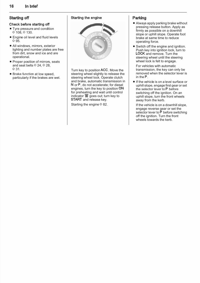
19 Selector lever, manualtransmission ......................... 87 Automatic transmission ........ 85
20 Storage tray ......................... 42
21 Ignition switch withsteering wheel lock ............ .. 82
22 Steering wheel adjustment ... 4923 Fuse box ............................ 106
24 Bonnet release lever ............ 94
25 Headlight rangeadjustment ........................... 65Front fog lights ..................... 66Traction Control system ....... 89
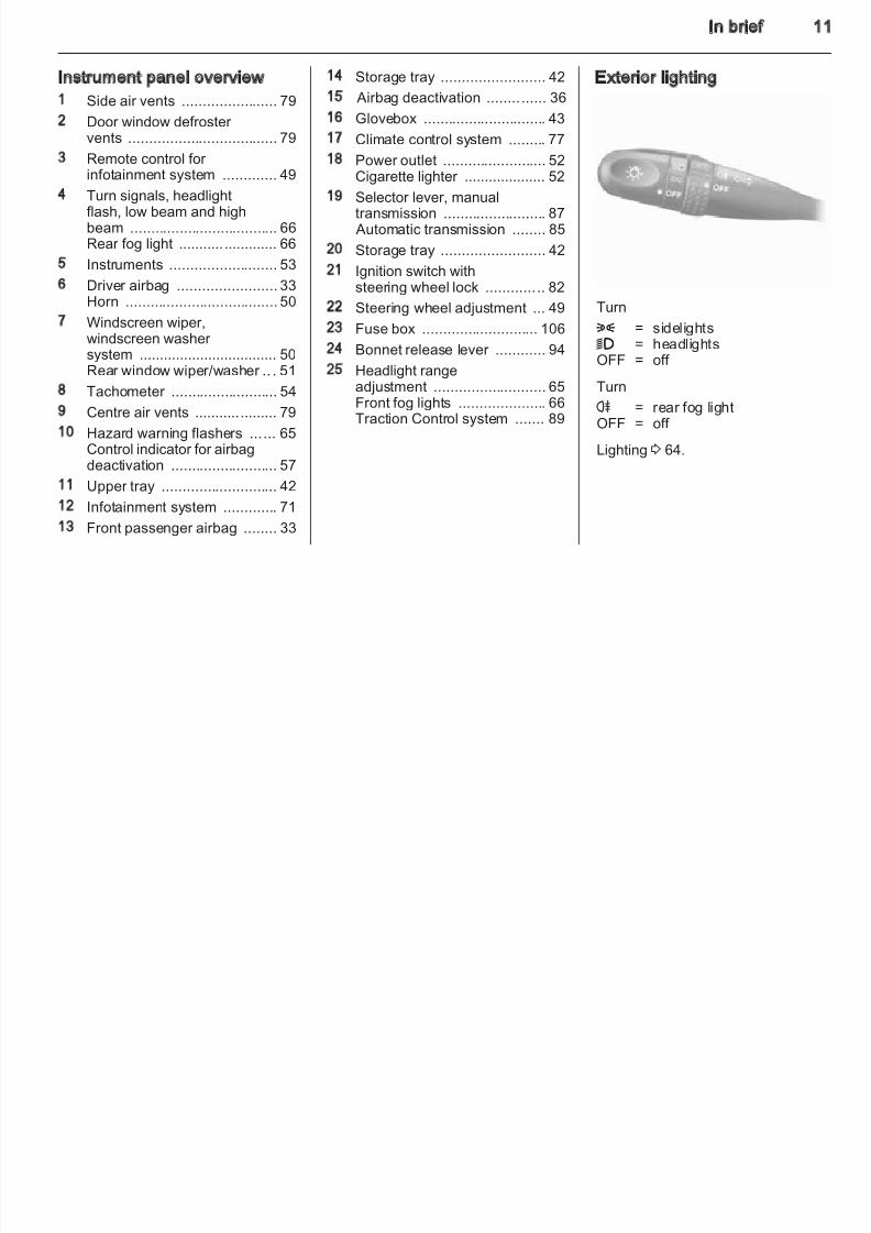
Exterior lighting
Turn8 = sidelights9 = headlightsOFF = off
Turn
r = rear fog lightOFF = off
Lighting 3 64.
8/4/2019 Agila Owner's Manual - August 2009
http://slidepdf.com/reader/full/agila-owners-manual-august-2009 13/137
12 In brief
Front fog lights
Operated with the > button.Front fog lights will only operate whenthe headlights or sidelights areswitched on.
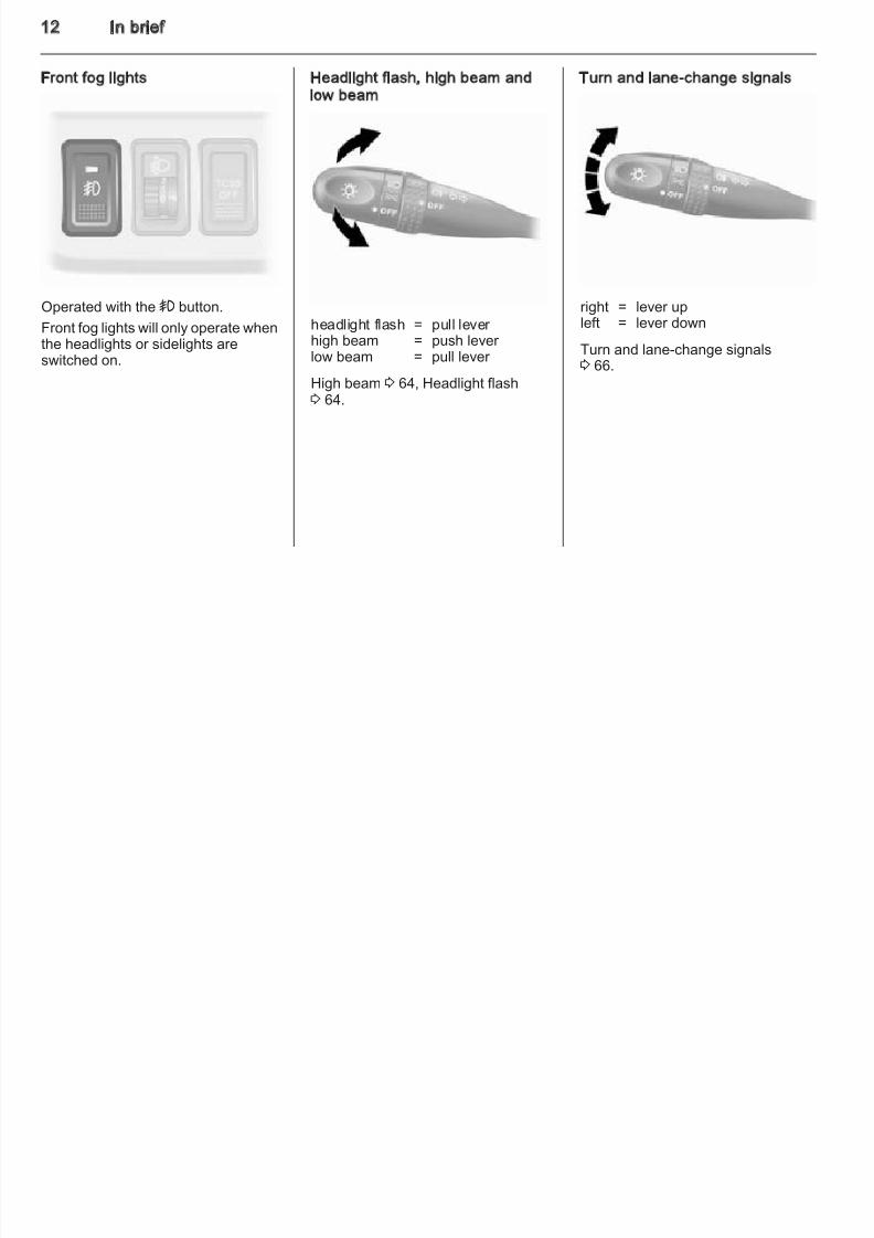
Headlight flash, high beam andlow beam
headlight flash = pull lever high beam = push lever low beam = pull lever
High beam 3 64, Headlight flash3 64.
Turn and lane-change signals
right = lever upleft = lever down
Turn and lane-change signals3 66.
8/4/2019 Agila Owner's Manual - August 2009
http://slidepdf.com/reader/full/agila-owners-manual-august-2009 14/137
In brief 1
Hazard warning flashers
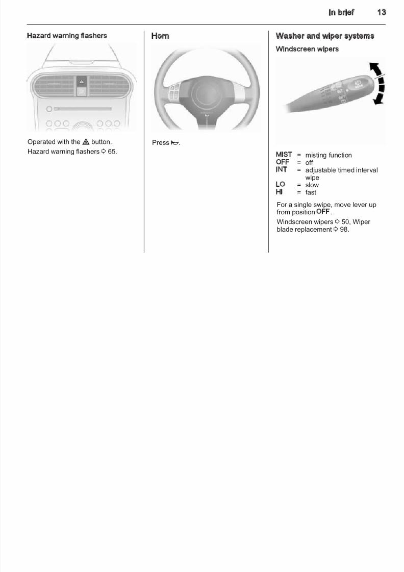
Operated with the ¨ button.Hazard warning flashers 3 65.
Horn
Press j.
Washer and wiper systems
Windscreen wipers
MIST = misting functionOFF = off INT = adjustable timed interval
wipeLO = slowHI = fast
For a single swipe, move lever up
from position OFF.Windscreen wipers 3 50, Wiper blade replacement 3 98.
8/4/2019 Agila Owner's Manual - August 2009
http://slidepdf.com/reader/full/agila-owners-manual-august-2009 15/137
14 In brief
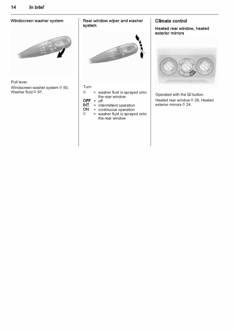
Windscreen washer system
Pull lever.Windscreen washer system 3 50,Washer fluid 3 97.
Rear window wiper and washersystem
Turn
f = washer fluid is sprayed ontothe rear window
OFF = off INT = intermittent operationON = continuous operationf = washer fluid is sprayed onto
the rear window
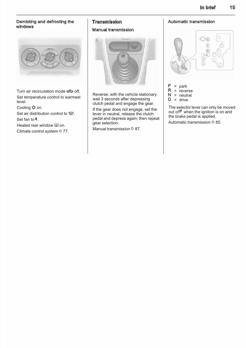
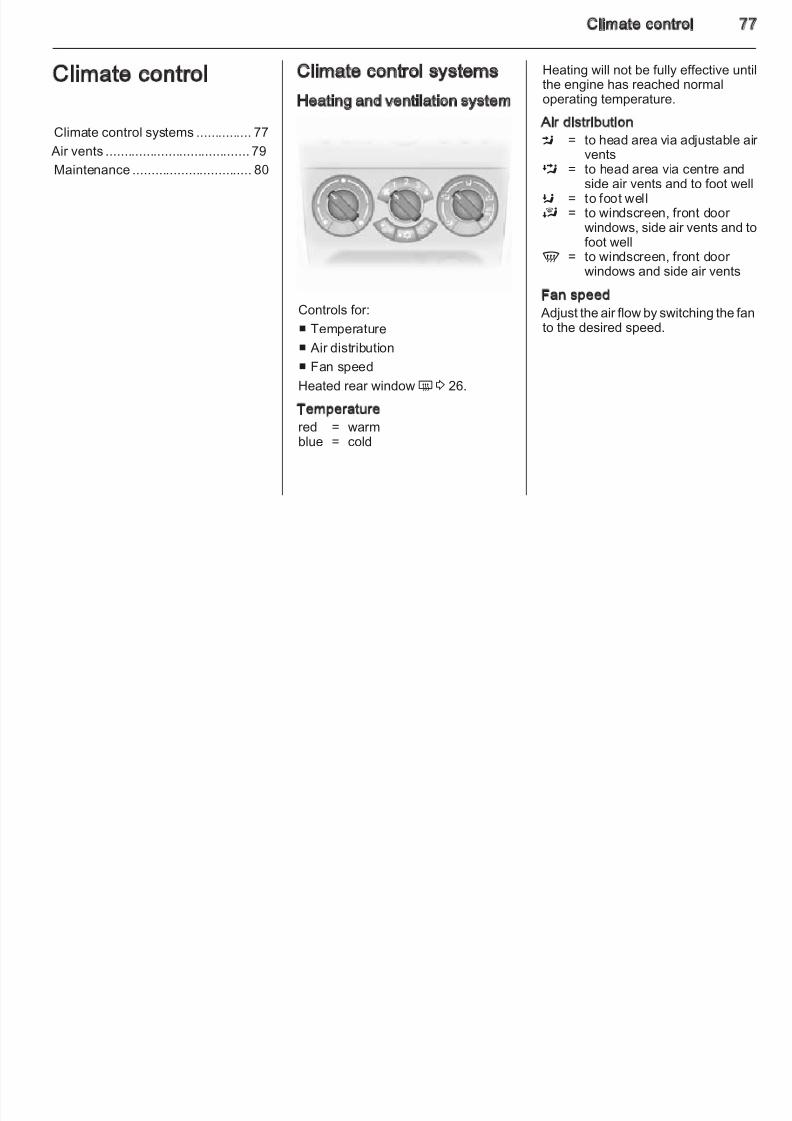
Climate control
Heated rear window, heatedexterior mirrors
Operated with the Ü button.
Heated rear window 3 26, Heatedexterior mirrors 3 24.
8/4/2019 Agila Owner's Manual - August 2009
http://slidepdf.com/reader/full/agila-owners-manual-august-2009 16/137
8/4/2019 Agila Owner's Manual - August 2009
http://slidepdf.com/reader/full/agila-owners-manual-august-2009 17/137
16 In brief
Starting off
Check before starting off■ Tyre pressure and condition3 108, 3 130.
■ Engine oil level and fluid levels3 95.
■ All windows, mirrors, exterior lighting and number plates are freefrom dirt, snow and ice and areoperational.
■ Proper position of mirrors, seatsand seat belts 3 24, 3 28,3 31.
■ Brake function at low speed,particularly if the brakes are wet.
Starting the engine
Turn key to position ACC. Move thesteering wheel slightly to release thesteering wheel lock. Operate clutchand brake, automatic transmission inN or P, do not accelerate; for dieselengines, turn the key to position ONfor preheating and wait until controlindicator ! goes out; turn key toSTART and release key.
Starting the engine3
82.
Parking
■ Always apply parking brake withoutpressing release button. Apply asfirmly as possible on a downhillslope or uphill slope. Operate footbrake at same time to reduceoperating force.
■ Switch off the engine and ignition.Push key into ignition lock, turn toLOCK and remove. Turn thesteering wheel until the steeringwheel lock is felt to engage.
For vehicles with automatic
transmission, the key can only beremoved when the selector lever isin the P.
■ If the vehicle is on a level surface or uphill slope, engage first gear or setthe selector lever to P beforeswitching off the ignition. On anuphill slope, turn the front wheelsaway from the kerb.
If the vehicle is on a downhill slope,engage reverse gear or set theselector lever to P before switchingoff the ignition. Tur n the frontwheels towards the kerb.
8/4/2019 Agila Owner's Manual - August 2009
http://slidepdf.com/reader/full/agila-owners-manual-august-2009 18/137
In brief 1
■ Lock the vehicle with button e onthe radio remote control.
Activate the anti-theft lockingsystem 3 22.
■ Do not park the vehicle on an easilyignitable surface. The hightemperature of the exhaust systemcould ignite the surface.
■ Close windows.
■ The engine cooling fans may runafter the engine has been switchedoff 3 94.
■ After running at high engine speeds
or with high engine loads, operatethe engine briefly at a low load or run in neutral for approx. 30seconds, before switching off inorder to protect the turbocharger.
Keys, locks 3 18, Laying the vehicleup for a long period of time 3 93.
8/4/2019 Agila Owner's Manual - August 2009
http://slidepdf.com/reader/full/agila-owners-manual-august-2009 19/137
18 Keys, doors and windows
Keys, doors andwindows
Keys, locks ................................... 18
Doors ........................................... 21
Vehicle security ............................ 22
Exterior mirrors ............................ 23
Interior mirrors ............................. 25
Windows ...................................... 25
Keys, locks
Keys
Replacement keys
The key number is specified on thekey or on a detachable tag.
The key number must be quotedwhen ordering replacement keys as itis a component of the immobiliser system.
Locks 3 119.
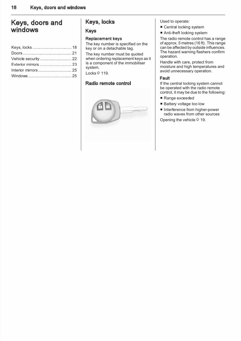
Radio remote control
Used to operate:
■ Central locking system
■ Anti-theft locking system
The radio remote control has a range
of approx. 5 metres (16 ft). This rangecan be affected by outside influences.The hazard warning flashers confirmoperation.
Handle with care, protect frommoisture and high temperatures andavoid unnecessary operation.
FaultIf the central locking system cannotbe operated with the radio remotecontrol, it may be due to the following:
■ Range exceeded
■ Battery voltage too low
■ Interference from higher-power radio waves from other sources
Opening the vehicle 3 19.
8/4/2019 Agila Owner's Manual - August 2009
http://slidepdf.com/reader/full/agila-owners-manual-august-2009 20/137
Keys, doors and windows 1
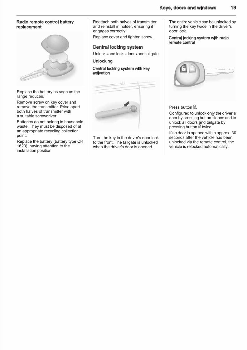
Radio remote control batteryreplacement
Replace the battery as soon as therange reduces.
Remove screw on key cover andremove the transmitter. Prise apartboth halves of transmitter witha suitable screwdriver.
Batteries do not belong in householdwaste. They must be disposed of at
an appropriate recycling collectionpoint.
Replace the battery (battery type CR1620), paying attention to theinstallation position.
Reattach both halves of transmitter and reinstall in holder, ensuring itengages correctly.
Replace cover and tighten screw.
Central locking system
Unlocks and locks doors and tailgate.
Unlocking
Central locking system with keyactivation
Turn the key in the driver's door lockto the front. The tailgate is unlockedwhen the driver's door is opened.
The entire vehicle can be unlocked bturning the key twice in the driver'sdoor lock.
Central locking system with radio
remote control
Press button c.
Configured to unlock only the driver`door by pressing button c once and tunlock all doors and tailgate bypressing button c twice.
If no door is opened within approx. 3seconds after the vehicle has beenunlocked via the remote control, thevehicle is relocked automatically.
8/4/2019 Agila Owner's Manual - August 2009
http://slidepdf.com/reader/full/agila-owners-manual-august-2009 21/137
20 Keys, doors and windows
LockingClose doors and tailgate.
Central locking system with keyactivation
Turn the key in the driver's door lockto the rear.
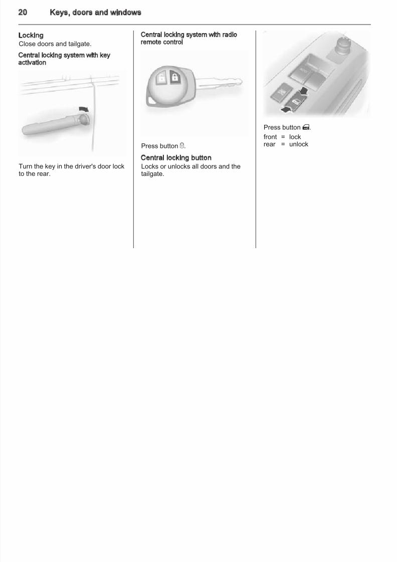
Central locking system with radioremote control
Press button e.
Central locking buttonLocks or unlocks all doors and thetailgate.
Press button m.
front = lockrear = unlock
8/4/2019 Agila Owner's Manual - August 2009
http://slidepdf.com/reader/full/agila-owners-manual-august-2009 22/137
Keys, doors and windows 2
Interior lock
Locks or unlocks the doors frominside the vehicle.
To lock front doors from outside thevehicle, press the interior lock andkeep exterior door handle raisedwhen closing the door.
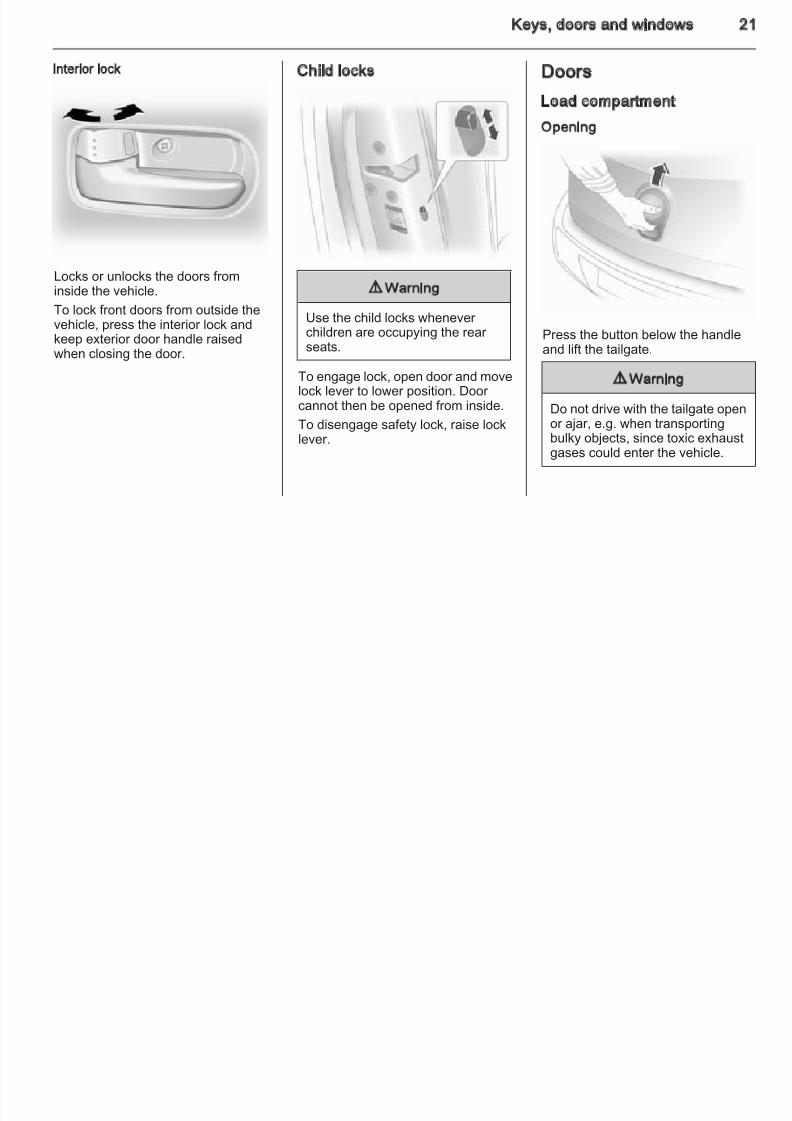
Child locks
9 Warning
Use the child locks whenever children are occupying the rear seats.
To engage lock, open door and movelock lever to lower position. Door cannot then be opened from inside.
To disengage safety lock, raise locklever.
Doors
Load compartment
Opening
Press the button below the handleand lift the tailgate.
9 Warning
Do not drive with the tailgate open
or ajar, e.g. when transportingbulky objects, since toxic exhaustgases could enter the vehicle.
8/4/2019 Agila Owner's Manual - August 2009
http://slidepdf.com/reader/full/agila-owners-manual-august-2009 23/137
22 Keys, doors and windows
NoticeThe installation of certain heavyaccessories onto the tailgate mayaffect its ability to remain open.
If the tailgate is open when the ignition
is switched on, control indicator yilluminates in the instrument cluster.
Central locking system 3 19.
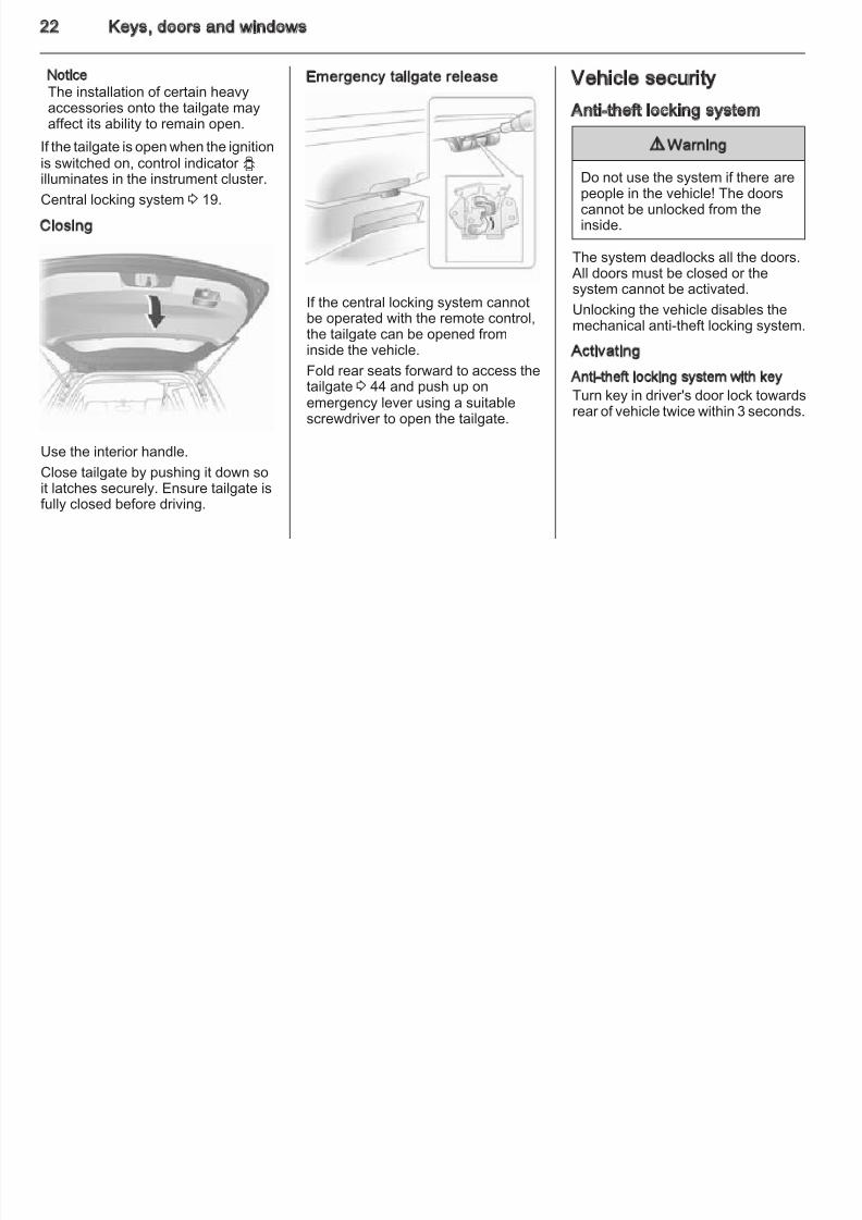
Closing
Use the interior handle.Close tailgate by pushing it down soit latches securely. Ensure tailgate isfully closed before driving.
Emergency tailgate release
If the central locking system cannotbe operated with the remote control,the tailgate can be opened frominside the vehicle.
Fold rear seats forward to access thetailgate 3 44 and push up onemergency lever using a suitablescrewdriver to open the tailgate.
Vehicle security
Anti-theft locking system
9 Warning
Do not use the system if there arepeople in the vehicle! The doorscannot be unlocked from theinside.
The system deadlocks all the doors. All doors must be closed or thesystem cannot be activated.
Unlocking the vehicle disables themechanical anti-theft locking system.
Activating
Anti-theft locking system with key
Turn key in driver's door lock towardsrear of vehicle twice within 3 seconds.
8/4/2019 Agila Owner's Manual - August 2009
http://slidepdf.com/reader/full/agila-owners-manual-august-2009 24/137
Keys, doors and windows 2
Anti-theft locking system with radioremote control
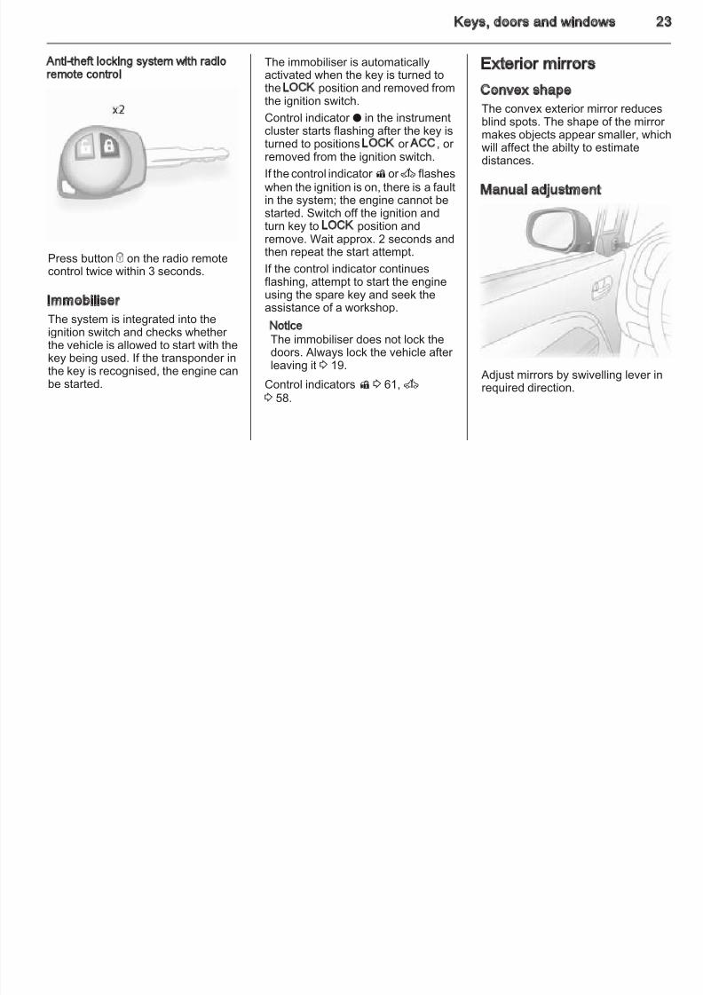
Press button e on the radio remotecontrol twice within 3 seconds.
Immobiliser
The system is integrated into theignition switch and checks whether the vehicle is allowed to start with thekey being used. If the transponder in
the key is recognised, the engine canbe started.
The immobiliser is automaticallyactivated when the key is turned tothe LOCK position and removed fromthe ignition switch.
Control indicator o in the instrument
cluster starts flashing after the key isturned to positions LOCK or ACC, or removed from the ignition switch.
If the control indicator dor A flasheswhen the ignition is on, there is a faultin the system; the engine cannot bestarted. Switch off the ignition andturn key to LOCK position andremove. Wait approx. 2 seconds and
then repeat the start attempt.If the control indicator continuesflashing, attempt to start the engineusing the spare key and seek theassistance of a workshop.
NoticeThe immobiliser does not lock thedoors. Always lock the vehicle after leaving it 3 19.
Control indicatorsd 3 61, A3 58.
Exterior mirrors
Convex shape
The convex exterior mirror reducesblind spots. The shape of the mirror makes objects appear smaller, whicwill affect the abilty to estimatedistances.
Manual adjustment
Adjust mirrors by swivelling lever inrequired direction.
8/4/2019 Agila Owner's Manual - August 2009
http://slidepdf.com/reader/full/agila-owners-manual-august-2009 25/137
24 Keys, doors and windows
Electric adjustment
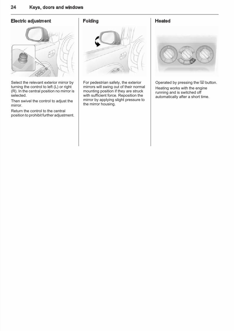
Select the relevant exterior mirror byturning the control to left (L) or right(R). In the central position no mirror isselected.
Then swivel the control to adjust themirror.
Return the control to the centralposition to prohibit further adjustment.
Folding
For pedestrian safety, the exterior mirrors will swing out of their normalmounting position if they are struckwith sufficient force. Reposition themirror by applying slight pressure tothe mirror housing.
Heated
Operated by pressing the Ü button.Heating works with the enginerunning and is switched off automatically after a short time.
Keys, doors and windows 2
8/4/2019 Agila Owner's Manual - August 2009
http://slidepdf.com/reader/full/agila-owners-manual-august-2009 26/137
Interior mirrors
Manual anti-dazzle
To reduce dazzle, adjust the lever onthe underside of the mirror housing.
Windows
Manual windows
The door windows can be opened or closed with the window winders.
Power windows
9 Warning
Take care when operating thepower windows. Risk of injury,particularly to children.
If there is a child on the frontpassenger seat, switch on thechild safety system for the power windows.
Keep a close watch on thewindows when closing them.Ensure that nothing becomestrapped in them as they move.
Power windows can be operated withkey in ignition switch position ON.
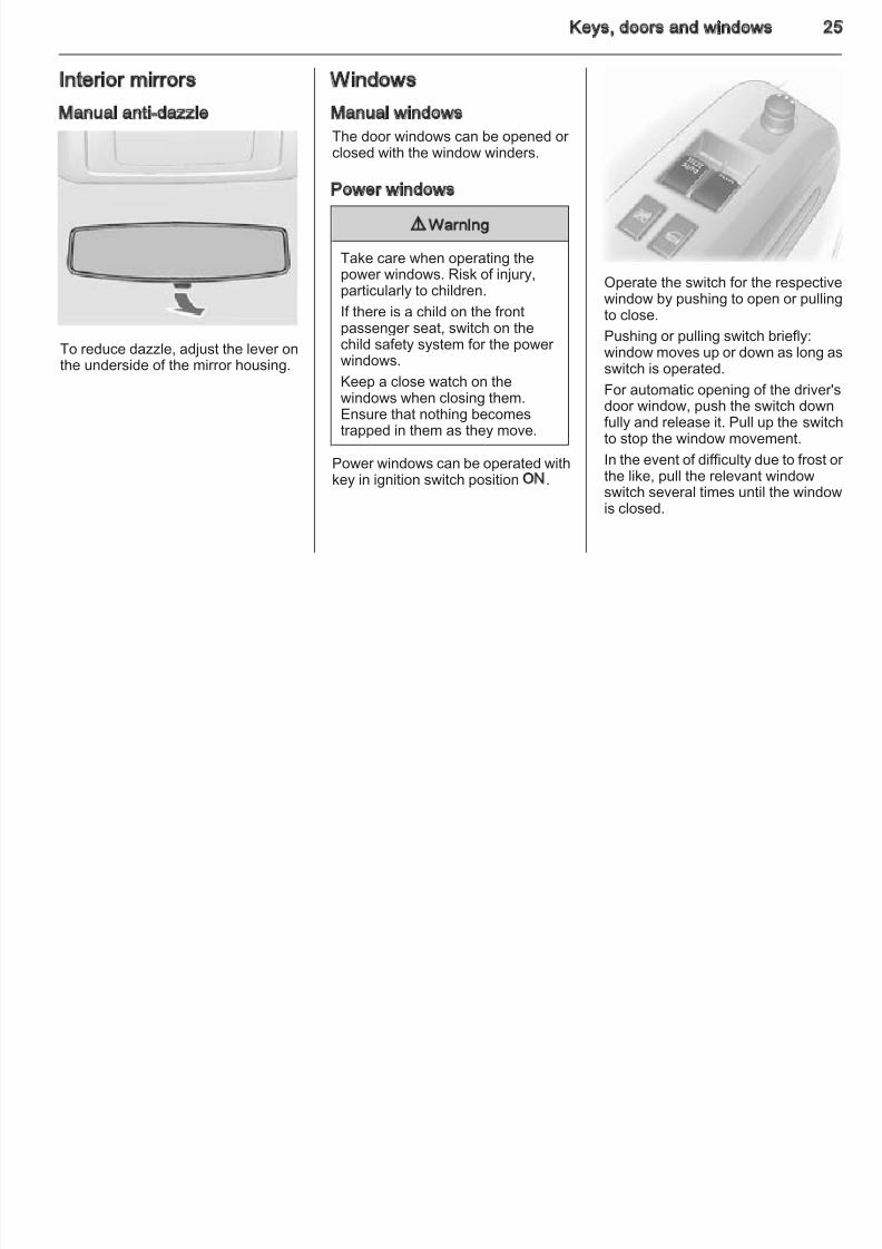
Operate the switch for the respectivwindow by pushing to open or pullin
to close.Pushing or pulling switch briefly:window moves up or down as long aswitch is operated.
For automatic opening of the driver'sdoor window, push the switch downfully and release it. Pull up the switcto stop the window movement.
In the event of difficulty due to frost othe like, pull the relevant windowswitch several times until the windowis closed.
26 Keys, doors and windows
8/4/2019 Agila Owner's Manual - August 2009
http://slidepdf.com/reader/full/agila-owners-manual-august-2009 27/137
Child safety system
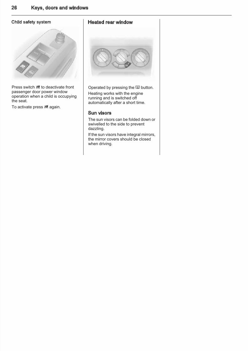
Press switch z to deactivate frontpassenger door power windowoperation when a child is occupyingthe seat.
To activate press z again.
Heated rear window
Operated by pressing the Ü button.Heating works with the enginerunning and is switched off automatically after a short time.
Sun visors
The sun visors can be folded down or swivelled to the side to preventdazzling.
If the sun visors have integral mirrors,the mirror covers should be closedwhen driving.
Seats, restraints 2
8/4/2019 Agila Owner's Manual - August 2009
http://slidepdf.com/reader/full/agila-owners-manual-august-2009 28/137
Seats, restraints
Head restraints ............................ 27
Front seats ................................... 28
Seat belts ..................................... 30
Airbag system .............................. 32
Child restraints ............................. 37
Head restraints
Position
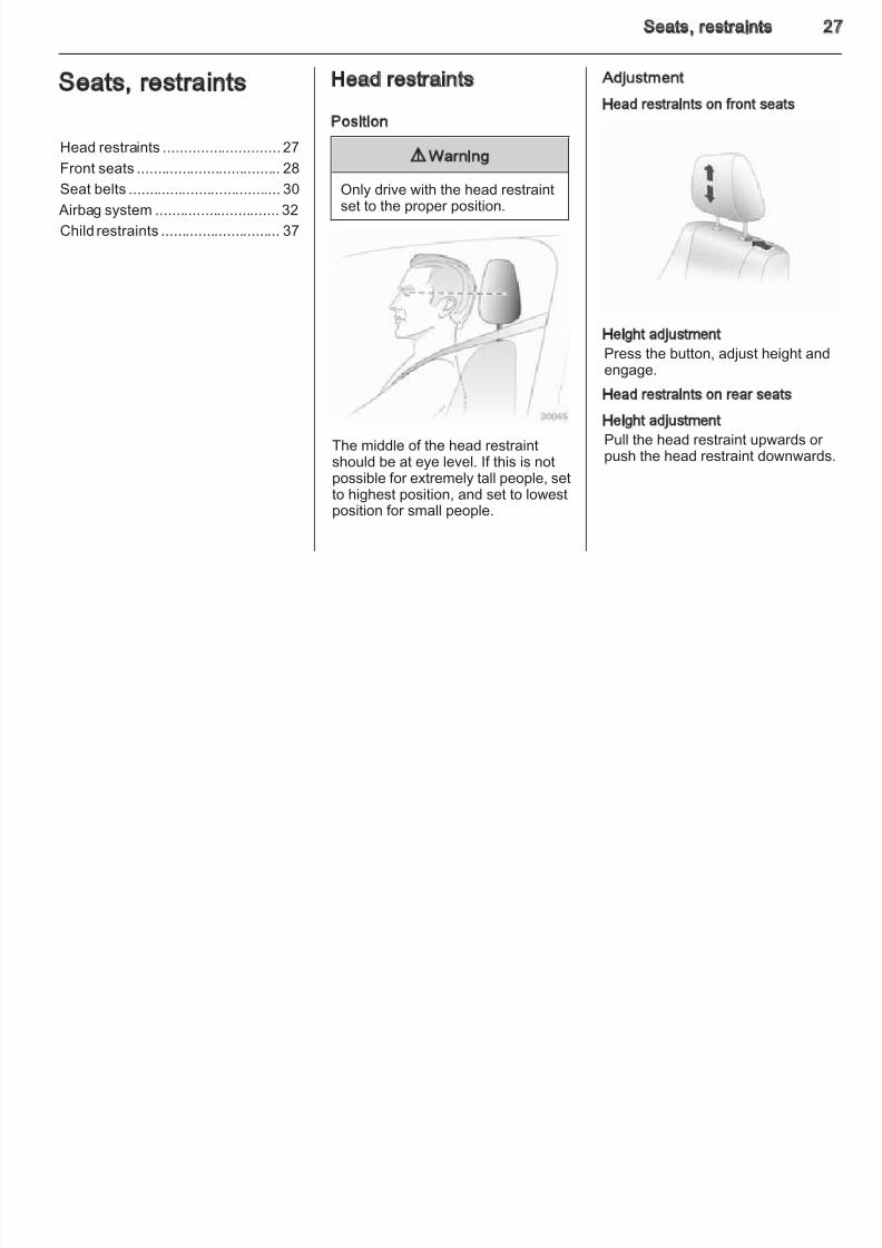
9Warning
Only drive with the head restraintset to the proper position.
The middle of the head restraintshould be at eye level. If this is notpossible for extremely tall people, setto highest position, and set to lowestposition for small people.
Adjustment
Head restraints on front seats
Height adjustment
Press the button, adjust height andengage.
Head restraints on rear seats
Height adjustment
Pull the head restraint upwards or push the head restraint downwards.
28 Seats, restraints
8/4/2019 Agila Owner's Manual - August 2009
http://slidepdf.com/reader/full/agila-owners-manual-august-2009 29/137
Front seats
Seat position
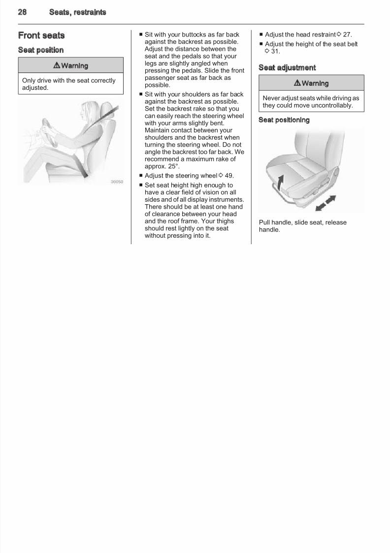
9 Warning
Only drive with the seat correctlyadjusted.
■ Sit with your buttocks as far backagainst the backrest as possible. Adjust the distance between theseat and the pedals so that your legs are slightly angled when
pressing the pedals. Slide the frontpassenger seat as far back aspossible.
■ Sit with your shoulders as far backagainst the backrest as possible.Set the backrest rake so that youcan easily reach the steering wheelwith your arms slightly bent.Maintain contact between your
shoulders and the backrest whenturning the steering wheel. Do notangle the backrest too far back. Werecommend a maximum rake of approx. 25°.
■ Adjust the steering wheel 3 49.
■ Set seat height high enough tohave a clear field of vision on allsides and of all display instruments.
There should be at least one handof clearance between your headand the roof frame. Your thighsshould rest lightly on the seatwithout pressing into it.
■ Adjust the head restraint 3 27.
■ Adjust the height of the seat belt3 31.
Seat adjustment
9 Warning
Never adjust seats while driving asthey could move uncontrollably.
Seat positioning
Pull handle, slide seat, releasehandle.
Seats, restraints 2
8/4/2019 Agila Owner's Manual - August 2009
http://slidepdf.com/reader/full/agila-owners-manual-august-2009 30/137
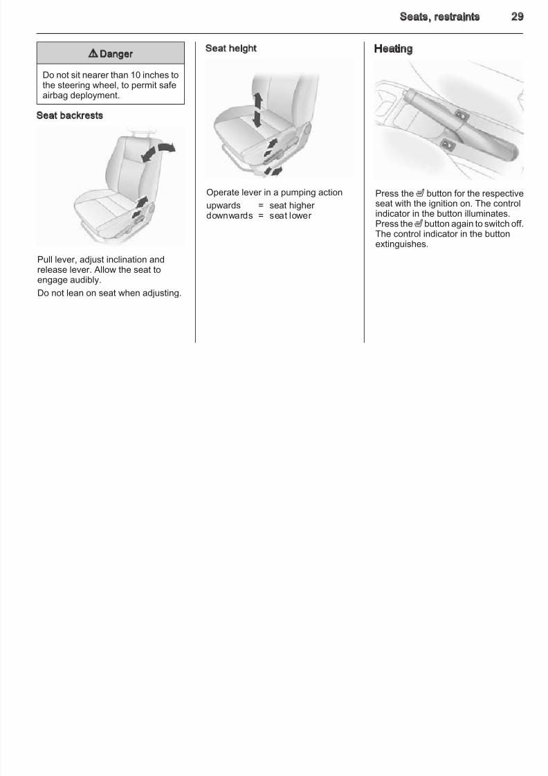
9 Danger
Do not sit nearer than 10 inches tothe steering wheel, to permit safeairbag deployment.
Seat backrests
Pull lever, adjust inclination andrelease lever. Allow the seat toengage audibly.
Do not lean on seat when adjusting.
Seat height
Operate lever in a pumping action
upwards = seat higher downwards = seat lower
Heating
Press theß button for the respectivseat with the ignition on. The controindicator in the button illuminates.Press theß button again to switch ofThe control indicator in the buttonextinguishes.
30 Seats, restraints
8/4/2019 Agila Owner's Manual - August 2009
http://slidepdf.com/reader/full/agila-owners-manual-august-2009 31/137
Seat belts
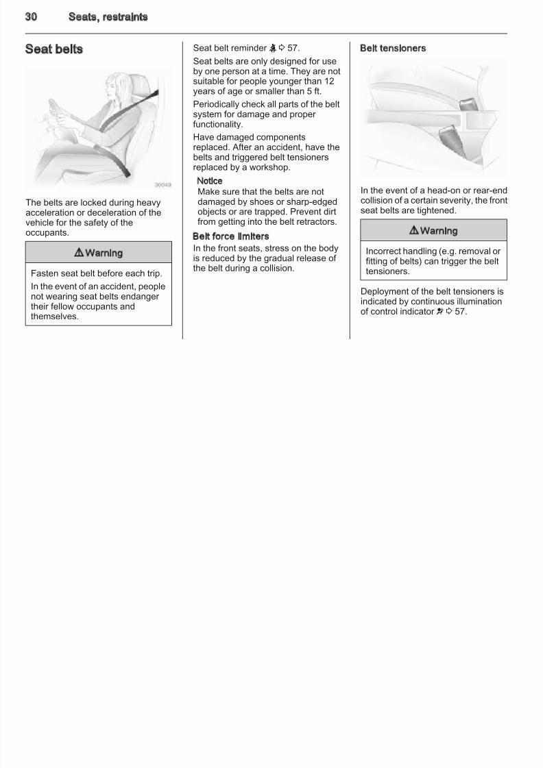
The belts are locked during heavyacceleration or deceleration of thevehicle for the safety of theoccupants.
9 Warning
Fasten seat belt before each trip.
In the event of an accident, peoplenot wearing seat belts endanger their fellow occupants andthemselves.
Seat belt reminder X 3 57.
Seat belts are only designed for useby one person at a time. They are notsuitable for people younger than 12years of age or smaller than 5 ft.
Periodically check all parts of the beltsystem for damage and proper functionality.
Have damaged componentsreplaced. After an accident, have thebelts and triggered belt tensionersreplaced by a workshop.
Notice
Make sure that the belts are notdamaged by shoes or sharp-edgedobjects or are trapped. Prevent dirtfrom getting into the belt retractors.
Belt force limitersIn the front seats, stress on the bodyis reduced by the gradual release of the belt during a collision.
Belt tensioners
In the event of a head-on or rear-endcollision of a certain severity, the frontseat belts are tightened.
9 Warning
Incorrect handling (e.g. removal or fitting of belts) can trigger the belttensioners.
Deployment of the belt tensioners isindicated by continuous illuminationof control indicator v 3 57.
Seats, restraints 3
8/4/2019 Agila Owner's Manual - August 2009
http://slidepdf.com/reader/full/agila-owners-manual-august-2009 32/137
Triggered belt tensioners must bereplaced by a workshop. Belttensioners can only be triggeredonce.
Notice
Do not affix or install accessories or other objects that may interfere withthe operation of the belt tensioners.Do not make any modifications tobelt tensioner components as thiswill invalidate the vehicle typeapproval.
Three-point seat belt
Fitting
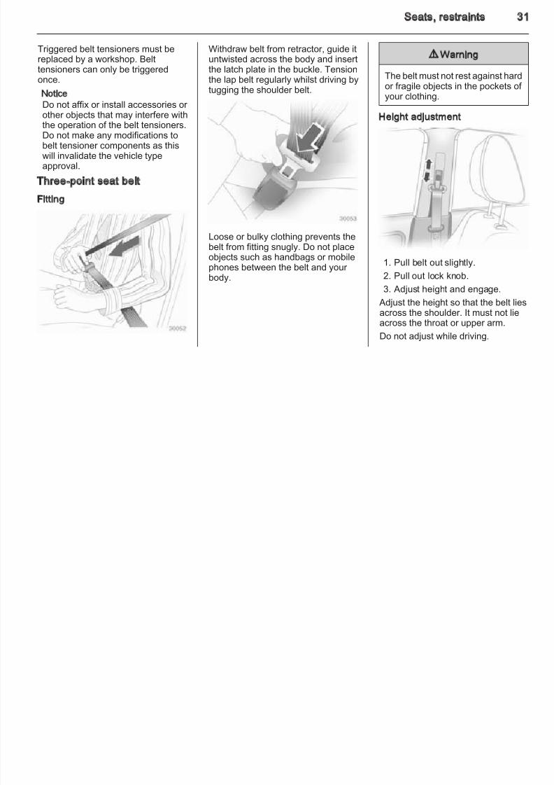
Withdraw belt from retractor, guide ituntwisted across the body and insertthe latch plate in the buckle. Tensionthe lap belt regularly whilst driving bytugging the shoulder belt.
Loose or bulky clothing prevents thebelt from fitting snugly. Do not placeobjects such as handbags or mobilephones between the belt and your body.
9 Warning
The belt must not rest against hardor fragile objects in the pockets of your clothing.
Height adjustment
1. Pull belt out slightly.
2. Pull out lock knob.
3. Adjust height and engage.
Adjust the height so that the belt liesacross the shoulder. It must not lieacross the throat or upper arm.
Do not adjust while driving.
32 Seats, restraints
8/4/2019 Agila Owner's Manual - August 2009
http://slidepdf.com/reader/full/agila-owners-manual-august-2009 33/137
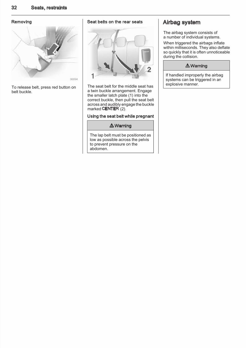
Removing
To release belt, press red button onbelt buckle.
Seat belts on the rear seats
The seat belt for the middle seat hasa twin buckle arrangement. Engagethe smaller latch plate (1) into thecorrect buckle, then pull the seat beltacross and audibly engage the bucklemarked CENTER (2).
Using the seat belt while pregnant
9 Warning
The lap belt must be positioned aslow as possible across the pelvisto prevent pressure on theabdomen.
Airbag system
The airbag system consists of a number of individual systems.
When triggered the airbags inflatewithin milliseconds. They also deflateso quickly that it is often unnoticeableduring the collision.
9 Warning
If handled improperly the airbagsystems can be triggered in anexplosive manner.
Seats, restraints 3
8/4/2019 Agila Owner's Manual - August 2009
http://slidepdf.com/reader/full/agila-owners-manual-august-2009 34/137
NoticeThe airbag systems and belttensioner control electronics arelocated in the centre console area.Do not put any magnetic objects in
this area.Do not stick anything on the airbagcovers and do not cover them withother materials.
Each airbag is triggered only once.Have deployed airbags replaced bya workshop.
Do not make any modifications tothe airbag system as this will
invalidate the vehicle type approval.In the event of airbag deploymenthave the steering wheel, theinstrument panel, all panelling parts,the door seals, the handles and theseats removed by a workshop.
Control indicator v for airbag systems3 57.
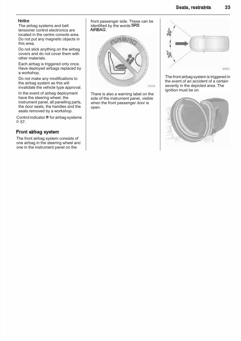
Front airbag system
The front airbag system consists of one airbag in the steering wheel andone in the instrument panel on the
front passenger side. These can beidentified by the words SRSAIRBAG.
There is also a warning label on theside of the instrument panel, visiblewhen the front passenger door isopen.
The front airbag system is triggered ithe event of an accident of a certain
severity in the depicted area. Theignition must be on.
34 Seats, restraints
8/4/2019 Agila Owner's Manual - August 2009
http://slidepdf.com/reader/full/agila-owners-manual-august-2009 35/137
The forward movement of the frontseat occupants is decelerated,thereby considerably reducing therisk of injury to the upper body andhead.
9 Warning
Optimum protection is onlyprovided when the seat is in theproper position 3 28.
Keep the area in which the airbaginflates clear of obstructions.
Fit the seat belt correctly and
engage securely. Only then theairbag is able to protect.
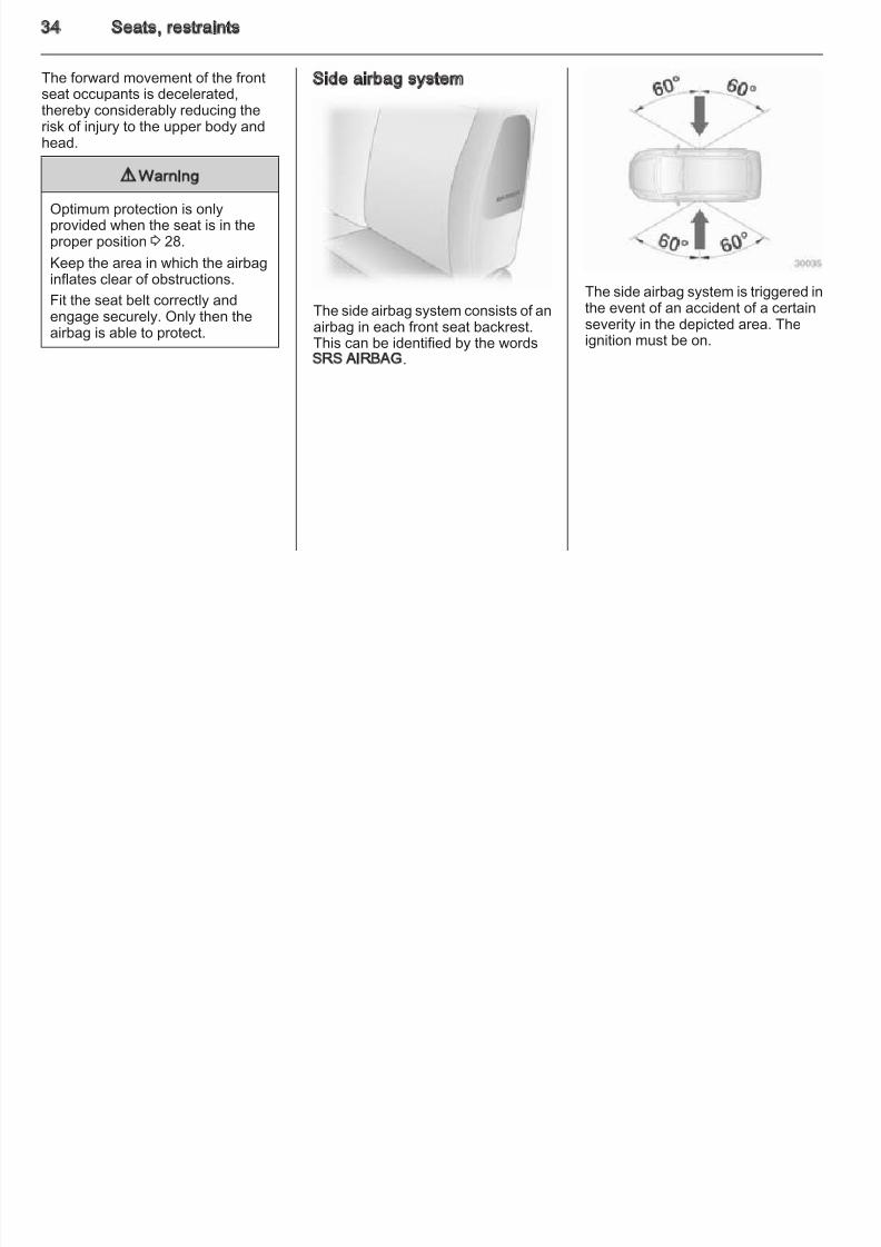
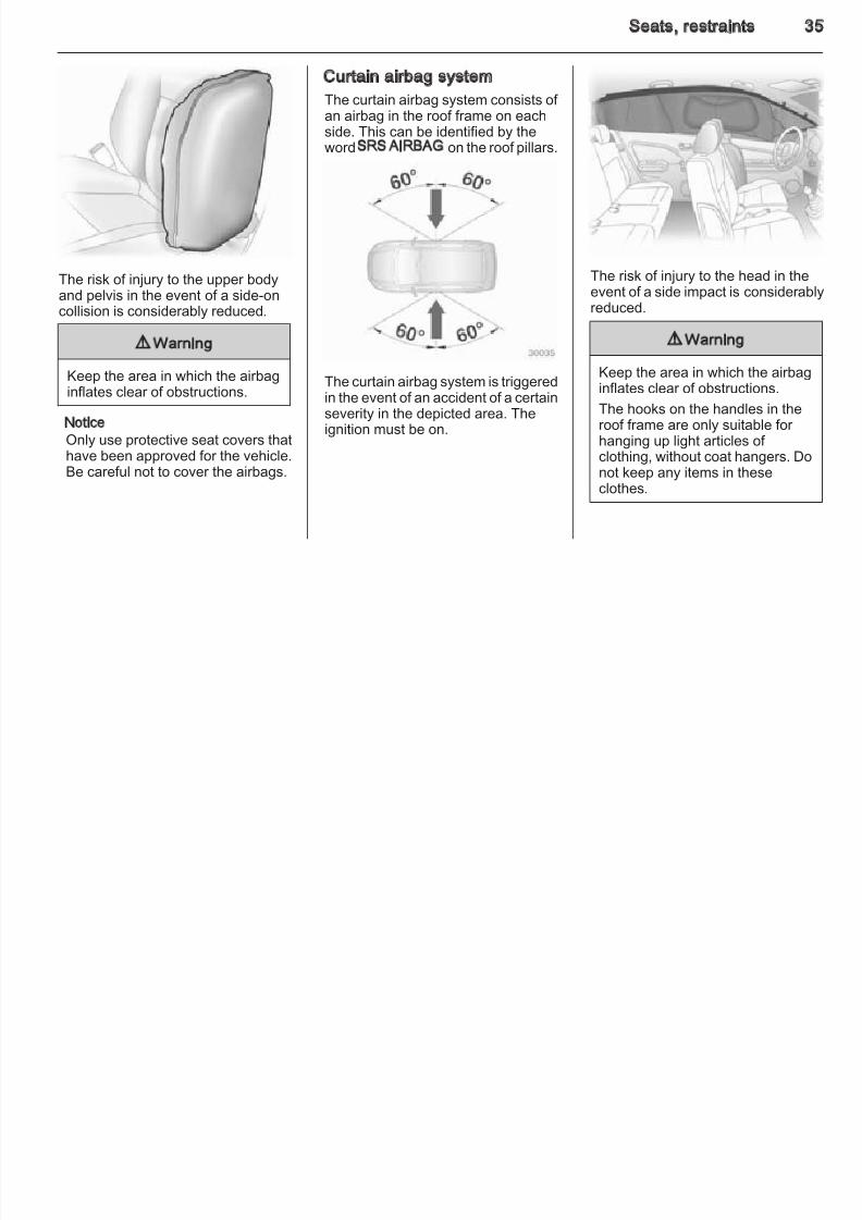
Side airbag system
The side airbag system consists of anairbag in each front seat backrest.This can be identified by the wordsSRS AIRBAG.
The side airbag system is triggered inthe event of an accident of a certain
severity in the depicted area. Theignition must be on.
Seats, restraints 3
8/4/2019 Agila Owner's Manual - August 2009
http://slidepdf.com/reader/full/agila-owners-manual-august-2009 36/137
The risk of injury to the upper bodyand pelvis in the event of a side-on
collision is considerably reduced.
9 Warning
Keep the area in which the airbaginflates clear of obstructions.
NoticeOnly use protective seat covers that
have been approved for the vehicle.Be careful not to cover the airbags.
Curtain airbag system
The curtain airbag system consists of an airbag in the roof frame on eachside. This can be identified by theword SRS AIRBAG on the roof pillars.
The curtain airbag system is triggeredin the event of an accident of a certainseverity in the depicted area. Theignition must be on.
The risk of injury to the head in theevent of a side impact is consider abl
reduced.
9 Warning
Keep the area in which the airbaginflates clear of obstructions.
The hooks on the handles in theroof frame are only suitable for hanging up light articles of
clothing, without coat hangers. Donot keep any items in theseclothes.
36 Seats, restraints
8/4/2019 Agila Owner's Manual - August 2009
http://slidepdf.com/reader/full/agila-owners-manual-august-2009 37/137
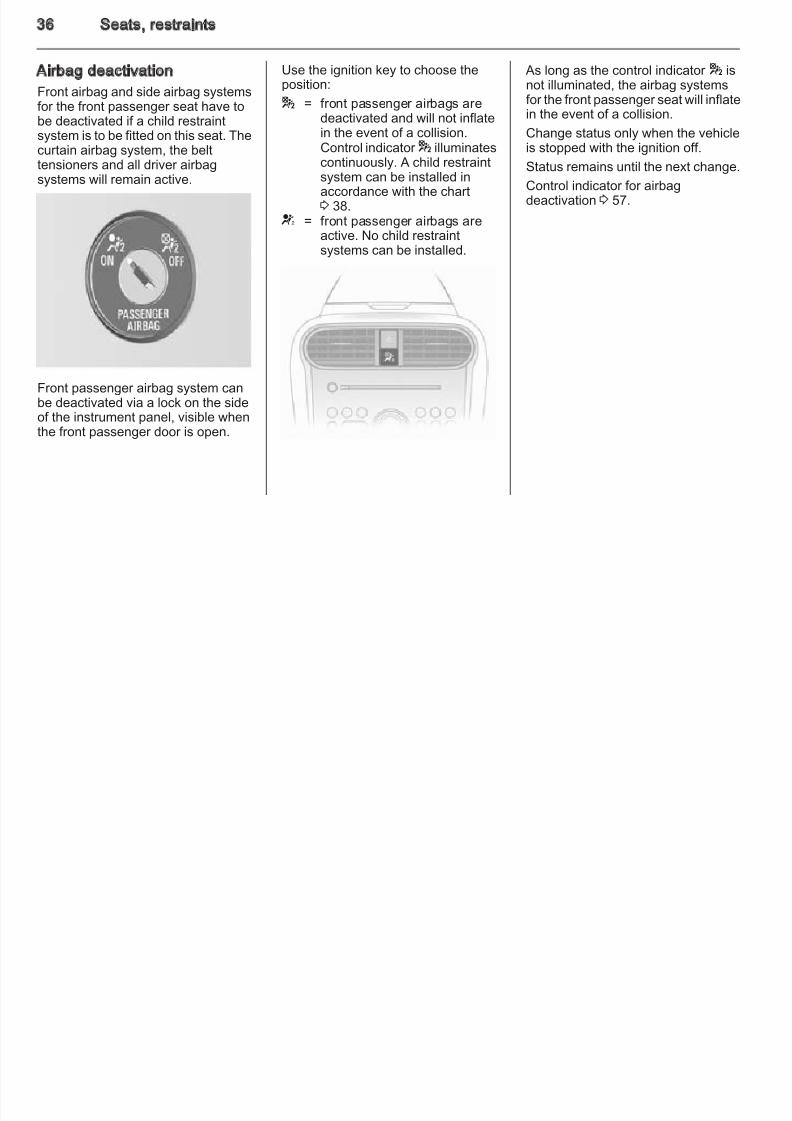
Airbag deactivation
Front airbag and side airbag systemsfor the front passenger seat have tobe deactivated if a child restraintsystem is to be fitted on this seat. The
curtain airbag system, the belttensioners and all driver airbagsystems will remain active.
Front passenger airbag system canbe deactivated via a lock on the sideof the instrument panel, visible whenthe front passenger door is open.
Use the ignition key to choose theposition:
* = front passenger airbags aredeactivated and will not inflatein the event of a collision.
Control indicator * illuminatescontinuously. A child restraintsystem can be installed inaccordance with the chart3 38.
V = front passenger airbags areactive. No child restraintsystems can be installed.
As long as the control indicator * isnot illuminated, the airbag systemsfor the front passenger seat will inflatein the event of a collision.
Change status only when the vehicle
is stopped with the ignition off.Status remains until the next change.
Control indicator for airbagdeactivation 3 57.
Seats, restraints 3
8/4/2019 Agila Owner's Manual - August 2009
http://slidepdf.com/reader/full/agila-owners-manual-august-2009 38/137
Child restraints
Child restraint systems
When a child restraint system is beingused, pay attention to the following
usage and installation instructionsand also those supplied with the childrestraint system.
Always comply with local or nationalregulations. In some countries, theuse of child restraint systems isforbidden on certain seats.
9 Warning
When using a child restraintsystem on the front passenger seat, the airbag systems for thefront passenger seat must bedeactivated; if not, the triggering of the airbags poses a risk of fatalinjury to the child.
This is especially the case if rear-
facing child restraint systems areused on the front passenger seat.
Selecting the right systemChildren should travel in a rear-facingchild restraint until as old as possible.It is appropriate to change the systemwhen the child's head can no longer
be properly supported at eye height.The child’s cervical vertebrae are stillvery weak and in an accident theysuffer less stress in the semi-pronerearward position than when sittingupright.
Children under 12 years or under 5 ft tall should only travel in anappropriate child restraint system.
Never carry a child while travelling inthe vehicle. The child will become tooheavy to hold in the event of a collision.
When transporting children, use thechild restraint systems suitable for thechild's weight.
Ensure that the child restraint systemto be installed is compatible with the
vehicle type.Ensure that the mounting location of the child restraint system within thevehicle is correct.
Only allow children to enter and exitthe vehicle at the side facing awayfrom the traffic.
When the child restraint system is noin use, secure the seat with a seat be
or remove it from the vehicle.NoticeDo not stick anything on the childrestraint systems and do not coverthem with any other materials.
A child restraint system which hasbeen subjected to stress in anaccident must be replaced.
38 Seats, restraints
8/4/2019 Agila Owner's Manual - August 2009
http://slidepdf.com/reader/full/agila-owners-manual-august-2009 39/137
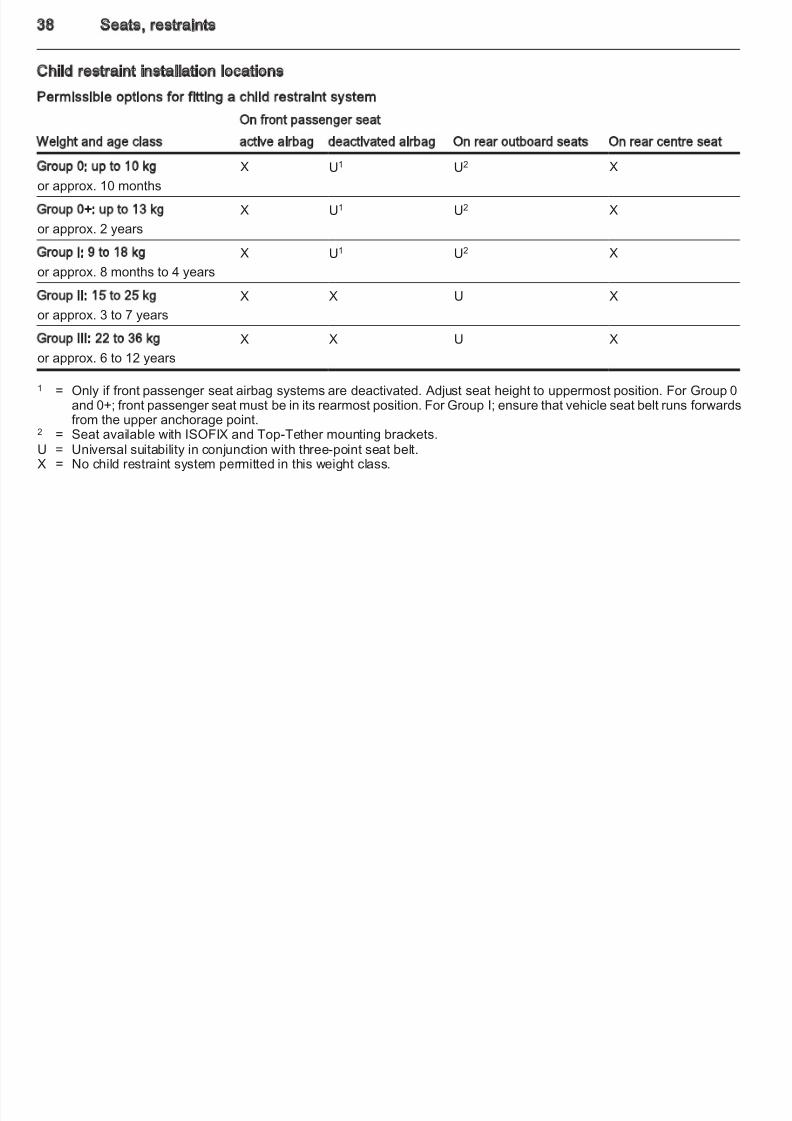
Child restraint installation locations
Permissible options for fitting a child restraint system
Weight and age class
On front passenger seat
On rear outboard seats On rear centre seatctive airbag deactivated airbag
Group 0: up to 10 kg
or approx. 10 months
X U1 U2 X
Group 0+: up to 13 kg
or approx. 2 years
X U1 U2 X
Group I: 9 to 18 kg
or approx. 8 months to 4 years
X U1 U2 X
Group II: 15 to 25 kg
or approx. 3 to 7 years
X X U X
Group III: 22 to 36 kg
or approx. 6 to 12 years
X X U X
1 = Only if front passenger seat airbag systems are deactivated. Adjust seat height to uppermost position. For Group 0and 0+; front passenger seat must be in its rearmost position. For Group I; ensure that vehicle seat belt runs forwards
from the upper anchorage point.2 = Seat available with ISOFIX and Top-Tether mounting brackets.U = Universal suitability in conjunction with three-point seat belt.X = No child restraint system permitted in this weight class.
Seats, restraints 3
8/4/2019 Agila Owner's Manual - August 2009
http://slidepdf.com/reader/full/agila-owners-manual-august-2009 40/137
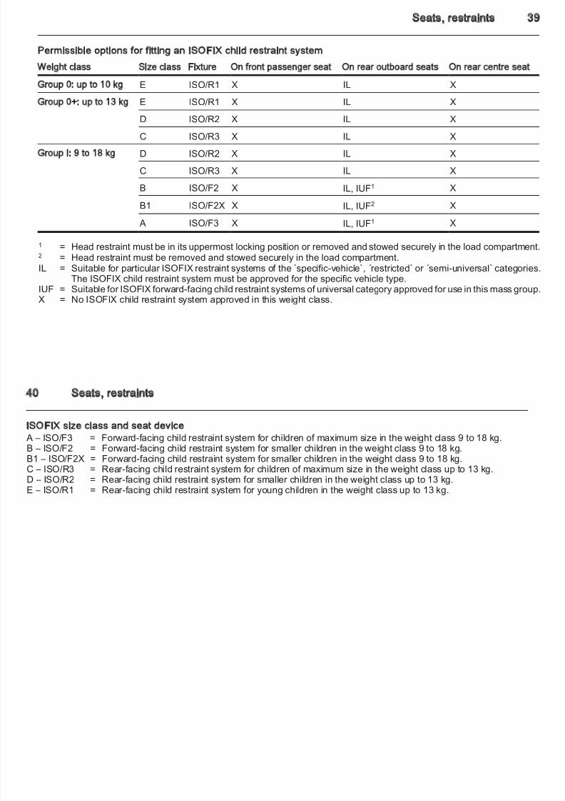
Permissible options for fitting an ISOFIX child restraint system
Weight class Size class Fixture On front passenger seat On rear outboard seats On rear centre seat
Group 0: up to 10 kg E ISO/R1 X IL X
Group 0+: up to 13 kg E ISO/R1 X IL X
D ISO/R2 X IL X
C ISO/R3 X IL X
Group I: 9 to 18 kg D ISO/R2 X IL X
C ISO/R3 X IL X
B ISO/F2 X IL, IUF1 X
B1 ISO/F2X X IL, IUF2 X
A ISO/F3 X IL, IUF1 X
1 = Head restraint must be in its uppermost locking position or removed and stowed securely in the load compartmen2 = Head restraint must be removed and stowed securely in the load compartment.IL = Suitable for particular ISOFIX restraint systems of the specific-vehicle`, restricted` or ´semi-universal` categories
The ISOFIX child restraint system must be approved for the specific vehicle type.IUF = Suitable for ISOFIX forward-facing child restraint systems of universal category approved for use in this mass groupX = No ISOFIX child restraint system approved in this weight class.
40 Seats, restraints
8/4/2019 Agila Owner's Manual - August 2009
http://slidepdf.com/reader/full/agila-owners-manual-august-2009 41/137
ISOFIX size class and seat device A – ISO/F3 = Forward-facing child restraint system for children of maximum size in the weight class 9 to 18 kg.B – ISO/F2 = Forward-facing child restraint system for smaller children in the weight class 9 to 18 kg.B1 – ISO/F2X = Forward-facing child restraint system for smaller children in the weight class 9 to 18 kg.C – ISO/R3 = Rear-facing child restraint system for children of maximum size in the weight class up to 13 kg.
D – ISO/R2 = Rear-facing child restraint system for smaller children in the weight class up to 13 kg.E – ISO/R1 = Rear-facing child restraint system for young children in the weight class up to 13 kg.
Seats, restraints 4
8/4/2019 Agila Owner's Manual - August 2009
http://slidepdf.com/reader/full/agila-owners-manual-august-2009 42/137
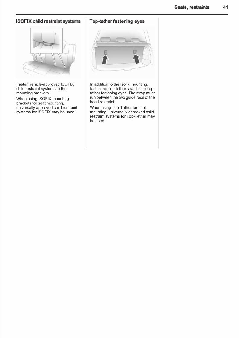
ISOFIX child restraint systems
Fasten vehicle-approved ISOFIX
child restraint systems to themounting brackets.
When using ISOFIX mountingbrackets for seat mounting,universally approved child restraintsystems for ISOFIX may be used.
Top-tether fastening eyes
In addition to the Isofix mounting,
fasten the Top-tether strap to the Top-tether fastening eyes. The strap mustrun between the two guide rods of thehead restraint.
When using Top-Tether for seatmounting, universally approved childrestraint systems for Top-Tether maybe used.
42 Storage
8/4/2019 Agila Owner's Manual - August 2009
http://slidepdf.com/reader/full/agila-owners-manual-august-2009 43/137
Storage
Storage compartments ................ 42
Load compartment ....................... 44Roof rack system ......................... 47
Loading information ..................... 47
Storage compartments
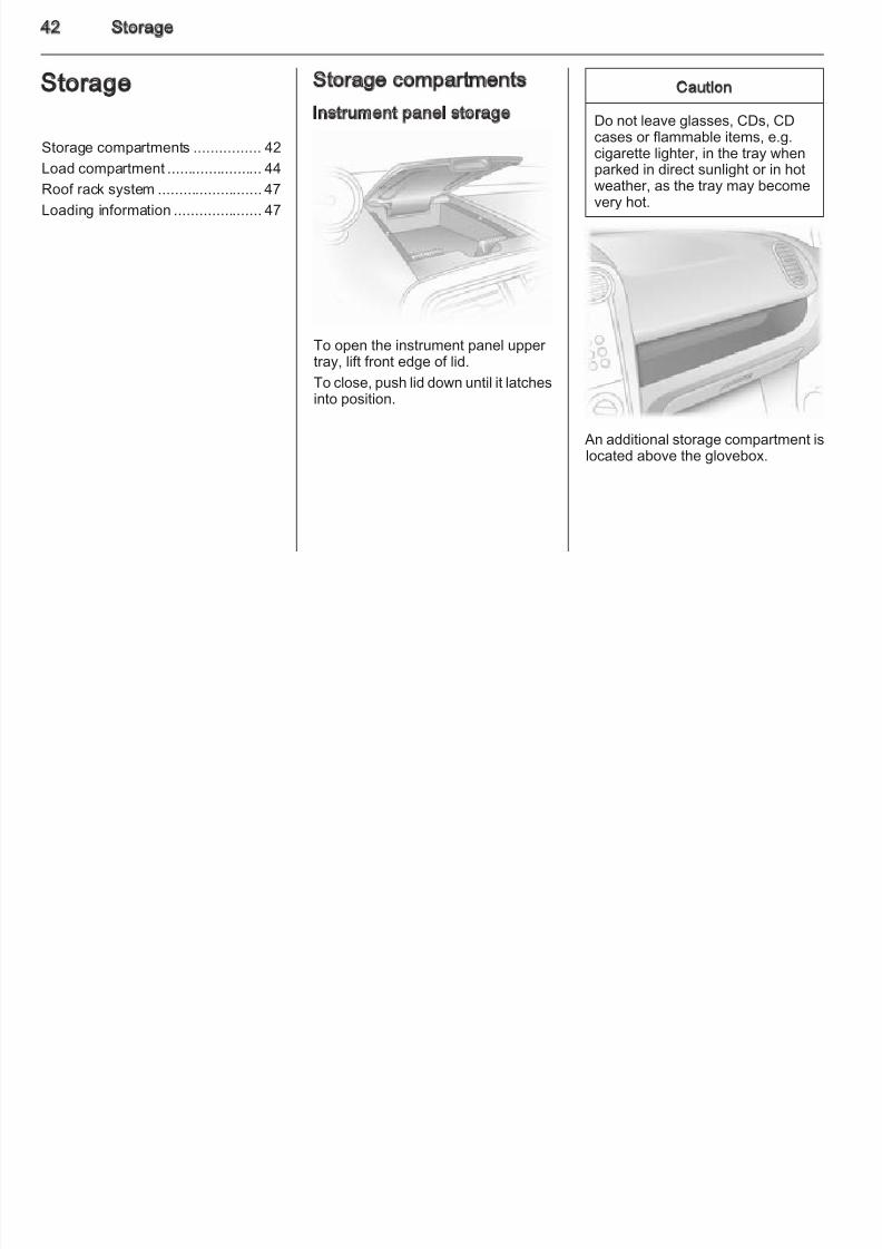
Instrument panel storage
To open the instrument panel upper tray, lift front edge of lid.
To close, push lid down until it latchesinto position.
Caution
Do not leave glasses, CDs, CDcases or flammable items, e.g.cigarette lighter, in the tray when
parked in direct sunlight or in hotweather, as the tray may becomevery hot.
An additional storage compartment islocated above the glovebox.
Storage 4
8/4/2019 Agila Owner's Manual - August 2009
http://slidepdf.com/reader/full/agila-owners-manual-august-2009 44/137
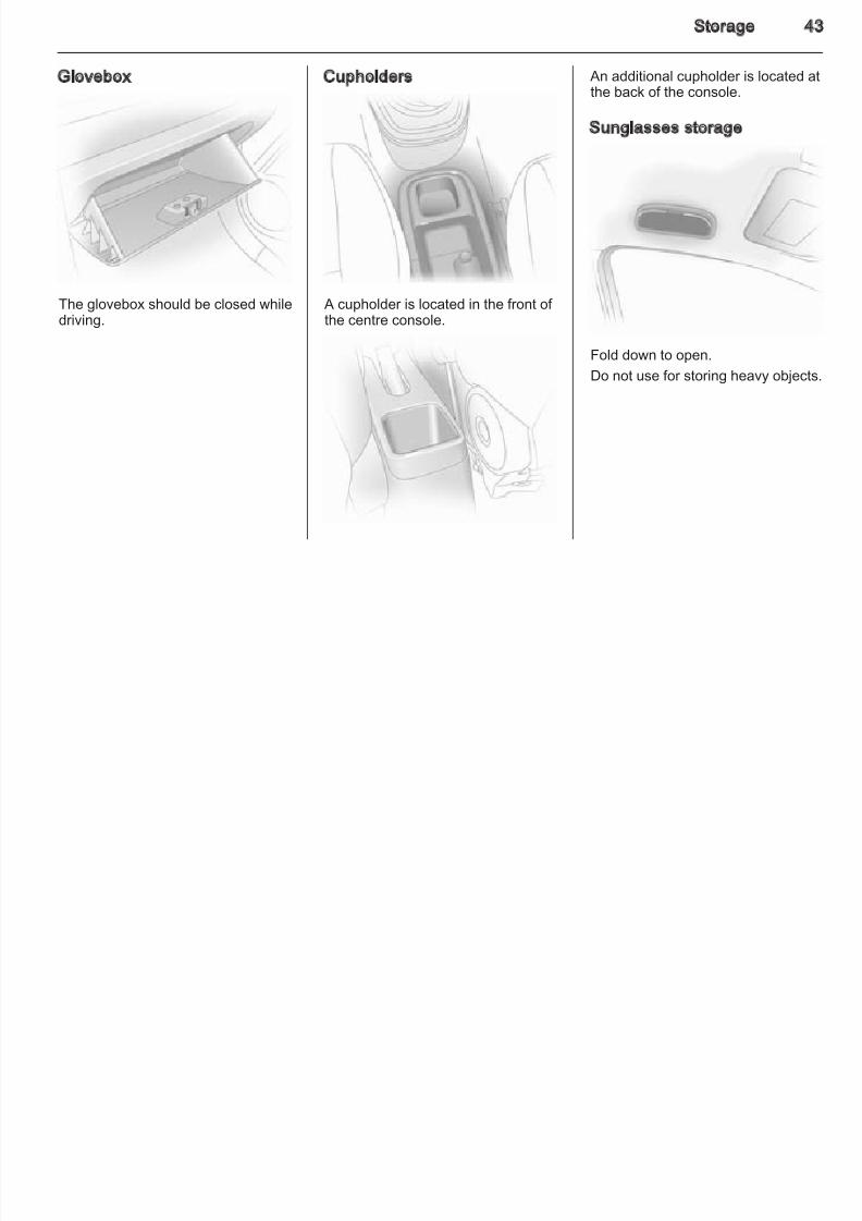
Glovebox
The glovebox should be closed while
driving.
Cupholders
A cupholder is located in the front of
the centre console.
An additional cupholder is located athe back of the console.
Sunglasses storage
Fold down to open.
Do not use for storing heavy objects
44 Storage
8/4/2019 Agila Owner's Manual - August 2009
http://slidepdf.com/reader/full/agila-owners-manual-august-2009 45/137
Load compartment
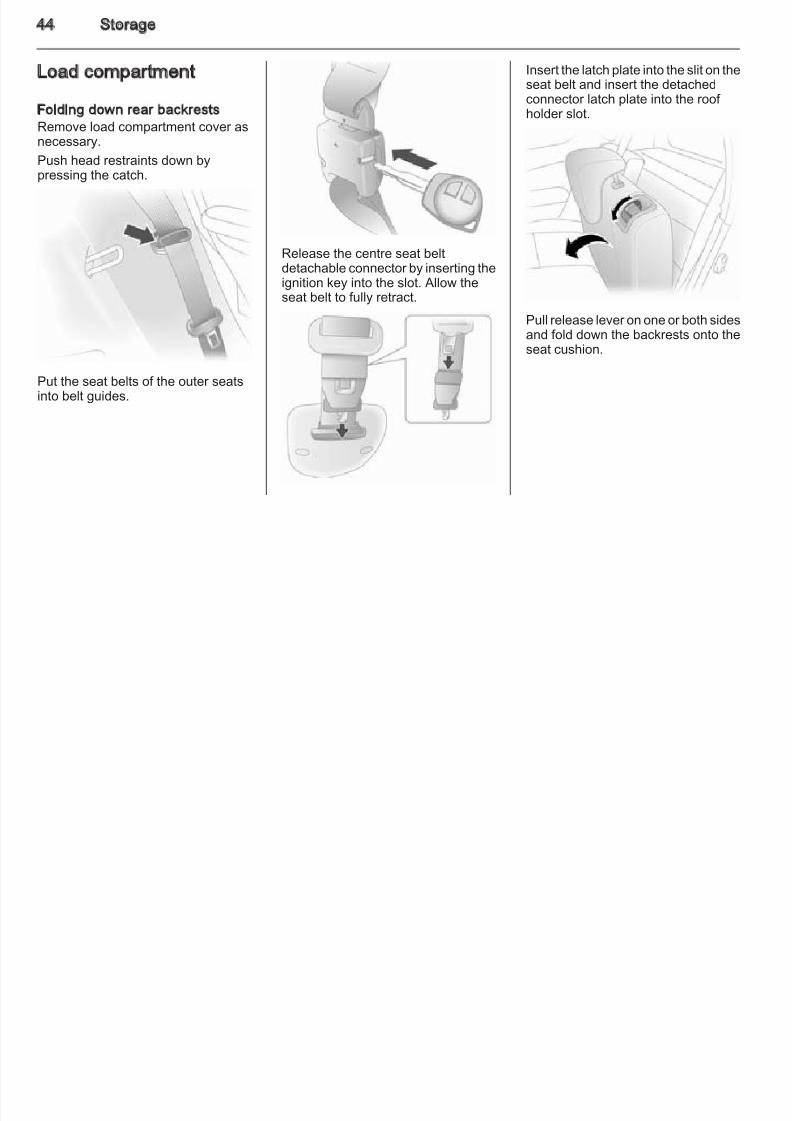
Folding down rear backrestsRemove load compartment cover asnecessary.
Push head restraints down bypressing the catch.
Put the seat belts of the outer seatsinto belt guides.
Release the centre seat beltdetachable connector by inserting theignition key into the slot. Allow theseat belt to fully retract.
Insert the latch plate into the slit on theseat belt and insert the detachedconnector latch plate into the roof holder slot.
Pull release lever on one or both sidesand fold down the backrests onto theseat cushion.
Storage 4
8/4/2019 Agila Owner's Manual - August 2009
http://slidepdf.com/reader/full/agila-owners-manual-august-2009 46/137
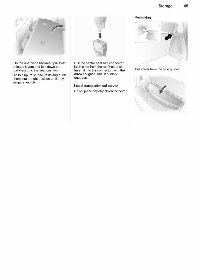
On the one piece backrest, pull bothrelease levers and fold down thebackrest onto the seat cushion.
To fold up, raise backrests and guidethem into upright position until theyengage audibly.
Pull the centre seat belt connector latch plate from the roof holder slot.Insert it into the connector, with thearrows aligned, until it audiblyengages.
Load compartment cover
Do not place any objects on the cover.
Removing
Pull cover from the side guides.
46 Storage
8/4/2019 Agila Owner's Manual - August 2009
http://slidepdf.com/reader/full/agila-owners-manual-august-2009 47/137
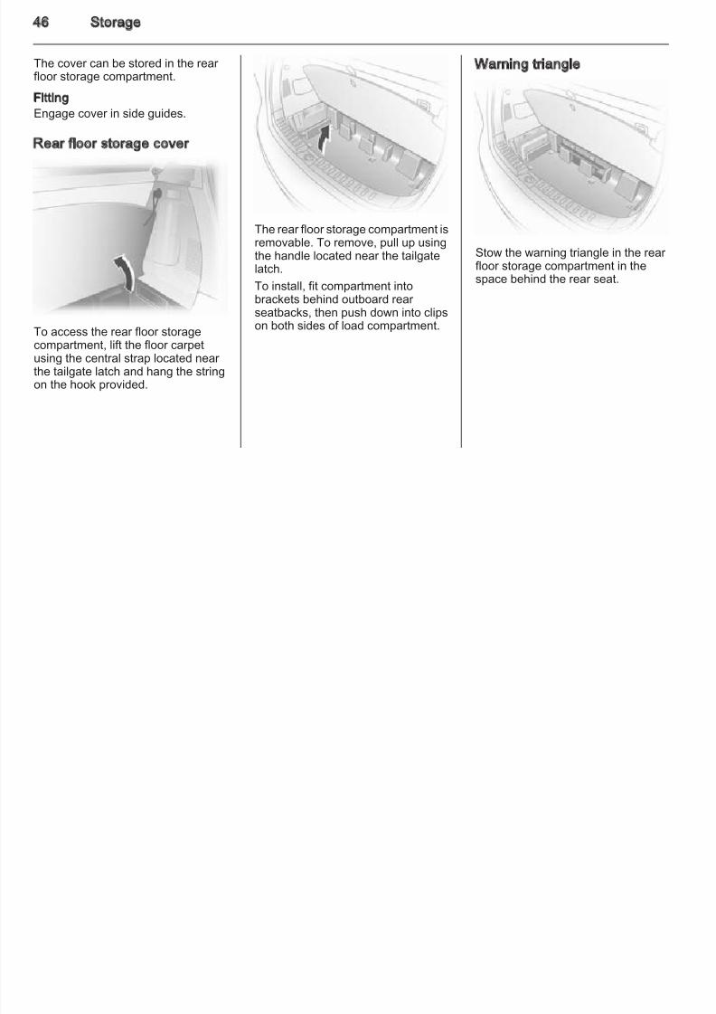
The cover can be stored in the rear floor storage compartment.
FittingEngage cover in side guides.
Rear floor storage cover
To access the rear floor storagecompartment, lift the floor carpetusing the central strap located near the tailgate latch and hang the string
on the hook provided.
The rear floor storage compartment isremovable. To remove, pull up usingthe handle located near the tailgatelatch.
To install, fit compartment intobrackets behind outboard rear seatbacks, then push down into clipson both sides of load compartment.
Warning triangle
Stow the warning triangle in the rear
floor storage compartment in thespace behind the rear seat.
Storage 4
8/4/2019 Agila Owner's Manual - August 2009
http://slidepdf.com/reader/full/agila-owners-manual-august-2009 48/137
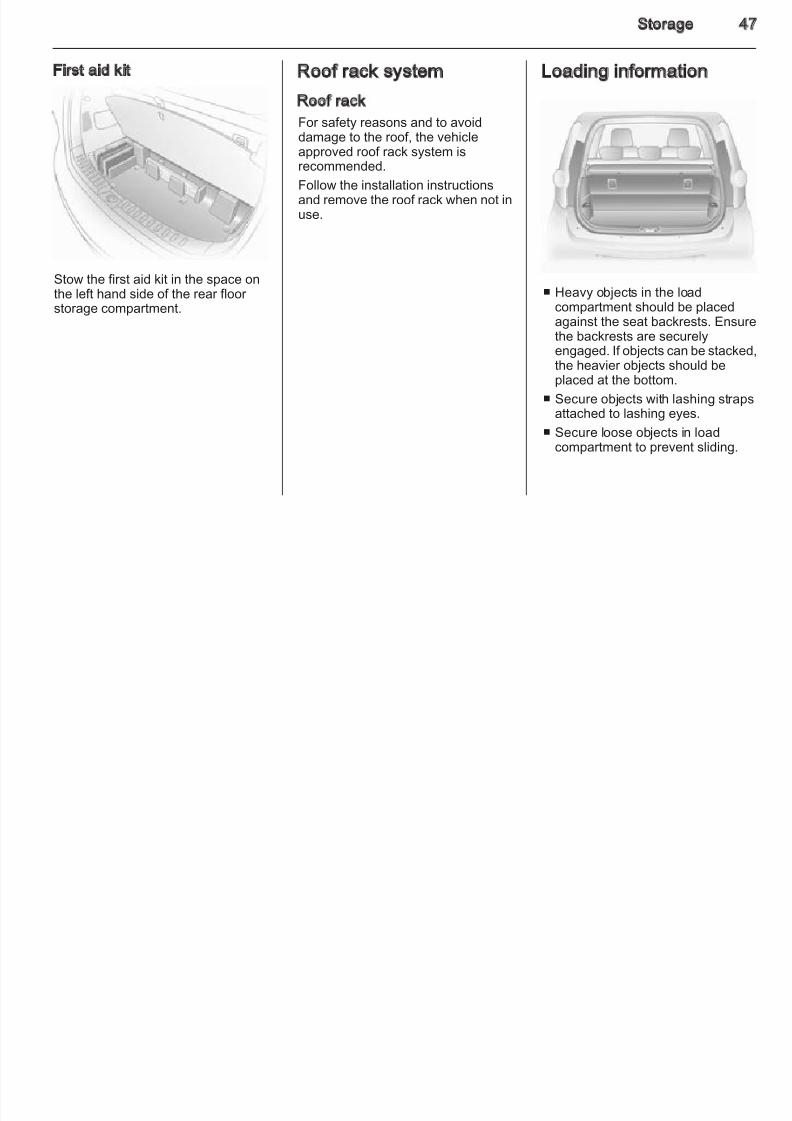
First aid kit
Stow the first aid kit in the space on
the left hand side of the rear floor storage compartment.
Roof rack system
Roof rack
For safety reasons and to avoiddamage to the roof, the vehicle
approved roof rack system isrecommended.
Follow the installation instructionsand remove the roof rack when not inuse.
Loading information
■ Heavy objects in the loadcompartment should be placedagainst the seat backrests. Ensurthe backrests are securelyengaged. If objects can be stackedthe heavier objects should beplaced at the bottom.
■ Secure objects with lashing strapsattached to lashing eyes.
■ Secure loose objects in loadcompartment to prevent sliding.
48 Storage
8/4/2019 Agila Owner's Manual - August 2009
http://slidepdf.com/reader/full/agila-owners-manual-august-2009 49/137
■ When transporting objects in theload compartment, the backrests of the rear seats must not be angledforward.
■ Do not allow the load to protrude
above the upper edge of thebackrests.
■ Do not place any objects on theload compartment cover or theinstrument panel, and do not cover the sensor on top of the instrumentpanel.
■ The load must not obstruct theoperation of the pedals, parking
brake and gear selector, or hinder the freedom of movement of thedriver. Do not place any unsecuredobjects in the interior.
■ Do not drive with an open loadcompartment.
■ The payload is the differencebetween the permitted grossvehicle weight (see identification
plate 3 125) and the EC kerbweight.
To calculate the EC kerb weight,enter the data for your vehicle in the
Weights table in the Introductionsection.
The EC kerb weight includesweights for the driver (68 kg),luggage (7 kg) and all fluids (tank
90% full).Optional equipment andaccessories increase the kerbweight.
■ Driving with a roof load increasesthe sensitivity of the vehicle tocross-winds and has a detrimentaleffect on vehicle handling due tothe vehicle’s higher centre of
gravity. Distribute the load evenlyand secure it properly with retainingstraps. Adjust the tyre pressure andvehicle speed according to the loadconditions. Check and retighten thestraps frequently.
The permissible roof load is 35 kg.The roof load is the combinedweight of the roof rack and the load.
Instruments and controls 4
8/4/2019 Agila Owner's Manual - August 2009
http://slidepdf.com/reader/full/agila-owners-manual-august-2009 50/137
Instruments andcontrols
Controls ....................................... 49Warning lights, gauges andindicators ..................................... 53
Vehicle messages ........................ 62
Trip computer ............................... 62
Controls
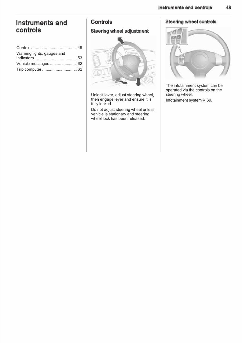
Steering wheel adjustment
Unlock lever, adjust steering wheel,then engage lever and ensure it isfully locked.
Do not adjust steering wheel unlessvehicle is stationary and steeringwheel lock has been released.
Steering wheel controls
The infotainment system can be
operated via the controls on thesteering wheel.
Infotainment system 3 69.
50 Instruments and controls
8/4/2019 Agila Owner's Manual - August 2009
http://slidepdf.com/reader/full/agila-owners-manual-august-2009 51/137
Horn
Press j.
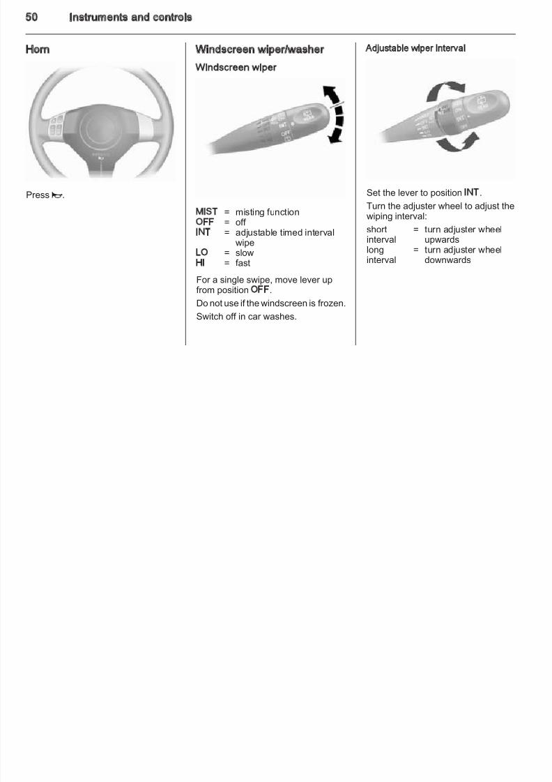
Windscreen wiper/washer
Windscreen wiper
MIST = misting functionOFF = off INT = adjustable timed interval
wipeLO = slowHI = fast
For a single swipe, move lever upfrom position OFF.
Do not use if the windscreen is frozen.
Switch off in car washes.
Adjustable wiper interval
Set the lever to position INT.
Turn the adjuster wheel to adjust thewiping interval:
shortinterval
= turn adjuster wheelupwards
longinterval
= turn adjuster wheeldownwards
Instruments and controls 5
8/4/2019 Agila Owner's Manual - August 2009
http://slidepdf.com/reader/full/agila-owners-manual-august-2009 52/137
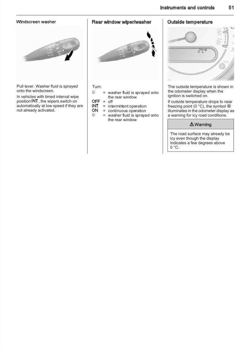
Windscreen washer
Pull lever. Washer fluid is sprayed
onto the windscreen.In vehicles with timed interval wipeposition INT, the wipers switch onautomatically at low speed if they arenot already activated.
Rear window wiper/washer
Turn:
f = washer fluid is sprayed ontothe rear window
OFF = off INT = intermittent operationON = continuous operationf = washer fluid is sprayed onto
the rear window
Outside temperature
The outside temperature is shown in
the odometer display when theignition is switched on.
If outside temperature drops to nearfreezing point (0 °C), the symbol Tilluminates in the odometer display aa warning for icy road conditions.
9 Warning
The road surface may already beicy even though the displayindicates a few degrees above0 °C.
52 Instruments and controls
P X t t h Electrical accessories that are
8/4/2019 Agila Owner's Manual - August 2009
http://slidepdf.com/reader/full/agila-owners-manual-august-2009 53/137
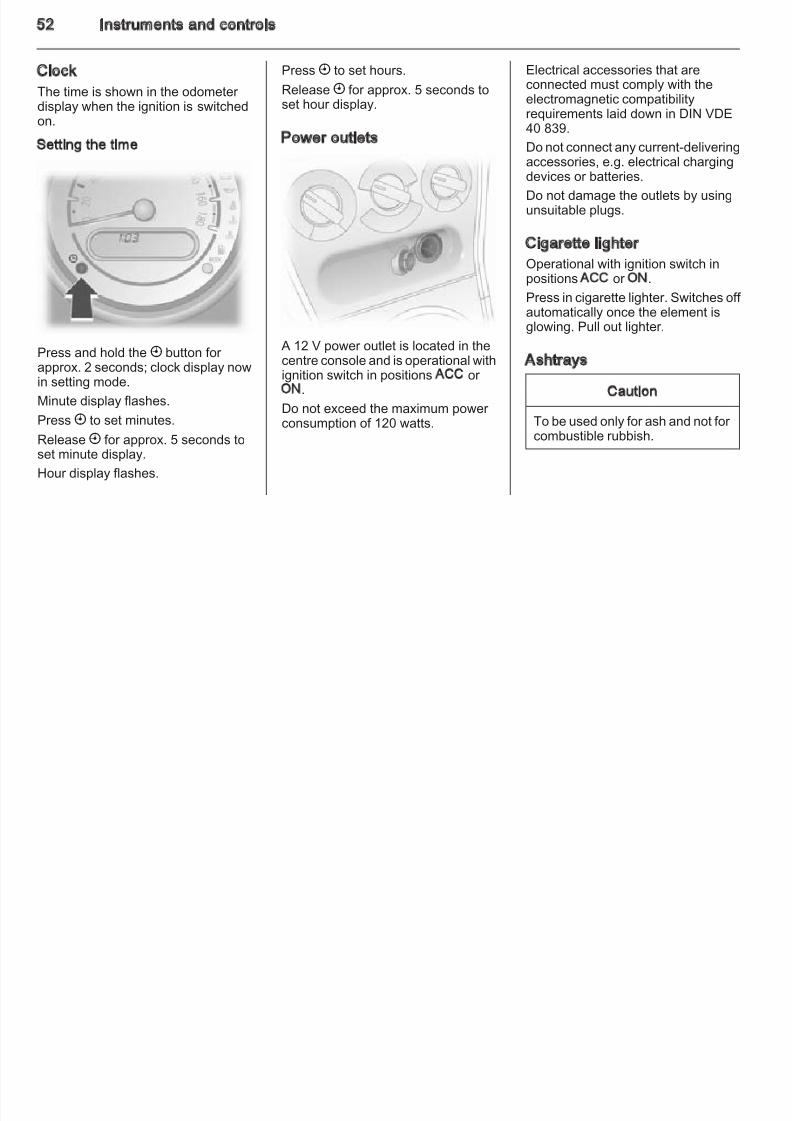
Clock
The time is shown in the odometer display when the ignition is switchedon.
Setting the time
Press and hold the X button for approx. 2 seconds; clock display nowin setting mode.
Minute display flashes.
Press X to set minutes.
Release X for approx. 5 seconds toset minute display.
Hour display flashes.
Press X to set hours.
Release X for approx. 5 seconds toset hour display.
Power outlets
A 12 V power outlet is located in thecentre console and is operational withignition switch in positions ACC or ON.
Do not exceed the maximum power consumption of 120 watts.
Electrical accessories that areconnected must comply with theelectromagnetic compatibilityrequirements laid down in DIN VDE40 839.
Do not connect any current-deliveringaccessories, e.g. electrical chargingdevices or batteries.
Do not damage the outlets by usingunsuitable plugs.
Cigarette lighter
Operational with ignition switch inpositions ACC or ON.
Press in cigarette lighter. Switches off automatically once the element isglowing. Pull out lighter.
Ashtrays
Caution
To be used only for ash and not for
combustible rubbish.
Instruments and controls 5
8/4/2019 Agila Owner's Manual - August 2009
http://slidepdf.com/reader/full/agila-owners-manual-august-2009 54/137
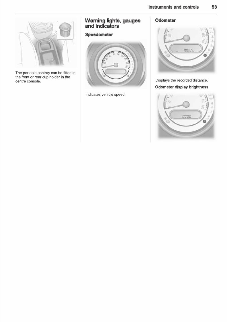
The portable ashtray can be fitted inthe front or rear cup holder in thecentre console.
Warning lights, gaugesand indicators
Speedometer
Indicates vehicle speed.
Odometer
Displays the recorded distance.
Odometer display brightness
54 Instruments and controls
To change brightness level switch on
8/4/2019 Agila Owner's Manual - August 2009
http://slidepdf.com/reader/full/agila-owners-manual-august-2009 55/137
To change brightness level, switch onheadlights and press the MODEbutton repeatedly until the squaresthat indicate the brightness levelappear in the odometer display.
⃞⃞⃞⃞ = maximum brightness⃞ = minimum brightness
Press and hold the MODE button tocycle through brightness levels.
Trip odometer
Displays the recorded distance sincethe last reset.
There are two independent tripodometers which indicate how far thevehicle has been driven since the lastreset.
Press the MODE button repeatedlyuntil A or B appears on the left of thedisplay.
To reset a trip odometer, press andhold the MODE button for approx.
2 seconds while the relevant tripodometer is displayed.
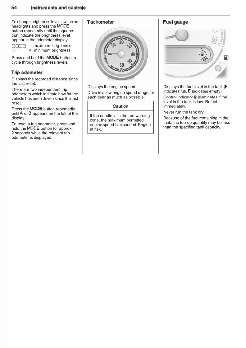
Tachometer
Displays the engine speed.
Drive in a low engine speed range for each gear as much as possible.
Caution
If the needle is in the red warningzone, the maximum permittedengine speed is exceeded. Engineat risk.
Fuel gauge
Displays the fuel level in the tank (F
indicates full, E indicates empty).Control indicator Y illuminates if thelevel in the tank is low. Refuelimmediately.
Never run the tank dry.
Because of the fuel remaining in thetank, the top-up quantity may be lessthan the specified tank capacity.
Instruments and controls 5
8/4/2019 Agila Owner's Manual - August 2009
http://slidepdf.com/reader/full/agila-owners-manual-august-2009 56/137
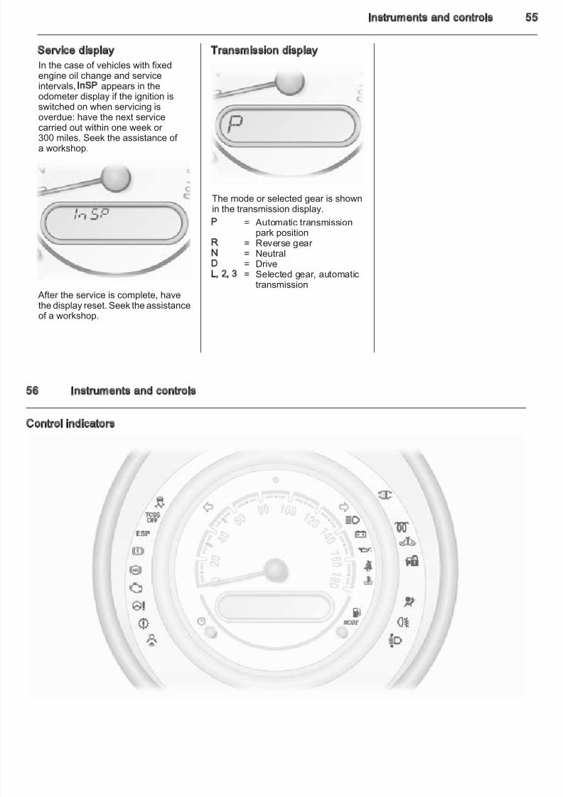
Service display
In the case of vehicles with fixedengine oil change and serviceintervals, InSP appears in theodometer display if the ignition is
switched on when servicing isoverdue: have the next servicecarried out within one week or 300 miles. Seek the assistance of a workshop.
After the service is complete, have
the display reset. Seek the assistanceof a workshop.
Transmission display
The mode or selected gear is shown
in the transmission display.P = Automatic transmission
park positionR = Reverse gear N = NeutralD = DriveL, 2, 3 = Selected gear, automatic
transmission
56 Instruments and controls
8/4/2019 Agila Owner's Manual - August 2009
http://slidepdf.com/reader/full/agila-owners-manual-august-2009 57/137
Control indicators
Instruments and controls 5
The control indicators described are Deployment of the belt tensioners o
8/4/2019 Agila Owner's Manual - August 2009
http://slidepdf.com/reader/full/agila-owners-manual-august-2009 58/137
The control indicators described arenot present in all vehicles. Thedescription applies to all instrumentversions. When the ignition isswitched on, most control indicatorswill illuminate briefly as a functionality
test.The control indicator colours mean:
red = danger, importantreminder
yellow = warning, information, faultgreen = confirmation of activationblue = confirmation of activation
Turn signalO flashes green.
Flashes if a turn signal or the hazardwarning flashers are activated.
Rapid flashing: failure of a turn signallight or associated fuse.
Bulb replacement 3 99.
Fuses 3 103.
Turn signals 3 66.
Seat belt reminder
X for driver seat illuminates or flashesred.
Illuminates After the ignition is switched on untilthe seat belt is fastened.
FlashesIf vehicle speed exceeds 9 mph anddriver seat belt is not fastened, X willflash for approx. 90 seconds alongwith a warning chime.
X will then illuminate until driver seatbelt is fastened.
Fastening the seat belt 3 31.
Airbag and belt tensioners
v illuminates red.
When the ignition is switched on, vflashes several times. If it does notflash when the ignition is switched on,stays lit, illuminates or flashes while
driving, there is a fault in the belttensioner or the airbag system. Theairbags and belt tensioners may fail totrigger in the event of an accident.
Deployment of the belt tensioners oairbags is indicated by continuousillumination of v.
9 Warning
Have the cause of the faultremedied immediately bya workshop.
Belt tensioners, airbag system 3 303 32.
Airbag deactivation
* for front passenger airbagilluminates or flashes yellow.
IlluminatesWhen the front and side airbagsystems for the front passenger seahave been deactivated.
FlashesWhen the ignition is switched on.
Airbag system 3 32, belt tensioners3 30.
58 Instruments and controls
Diesel engines Illuminates in combination with 8 if

8/4/2019 Agila Owner's Manual - August 2009
http://slidepdf.com/reader/full/agila-owners-manual-august-2009 59/137
Charging system
p illuminates red.
Illuminates when the ignition isswitched on and goes out shortly after the engine starts.
Illuminates when the engine isrunningStop, switch off engine. Battery is notcharging. Engine cooling may beinterrupted. Power to the brake servounit may be cut. Seek the assistanceof a workshop.
Malfunction indicator lightZ illuminates yellow.
Illuminates when the ignition isswitched on and goes out shortly after the engine starts.
Illuminates when the engine isrunningFault in the emission control system.
The permitted emission limits may beexceeded. Seek the assistance of a workshop immediately.
The engine stops and Z illuminatesif the fuel level is too low. If the tankhas been run dry, bleed the fuelsystem 3 98.
Vehicles with electric throttle bodysystemIf the battery has been disconnected,the system must be recalibrated uponreconnection of the battery. Holdignition key in ON position for 5 seconds without running theengine.
If the procedure is not successful Z
remains illuminated after the engineis started. Seek the assistance of a workshop immediately.
Service vehicle soon
Diesel enginesA illuminates or flashes in yellow.
Illuminates when the engine isrunning
Fault in the engine electronics. Seekthe assistance of a workshopimmediately.
cleaning of the diesel particle filter isnot successful or possible. Seek theassistance of a workshopimmediately. Diesel particle filter 3 83.
Flashes
When the ignition is switched on,there may be a fault in the immobiliser system; the engine cannot be started.
Immobiliser 3 23.
Brake system
R illuminates red.
Illuminates when the parking brake isreleased if the brake fluid level is toolow 3 97.
9 Warning
Stop. Do not continue your journey. Consult a workshop.
Illuminates after the ignition isswitched on if the parking brake isapplied 3 88.
Instruments and controls 5
Antilock brake system (ABS) Power steering If the vehicle’s battery has been
8/4/2019 Agila Owner's Manual - August 2009
http://slidepdf.com/reader/full/agila-owners-manual-august-2009 60/137
u illuminates yellow.
Illuminates briefly after the ignition isswitched on. The system is ready for operation when the u goes out.
If u does not go out after a fewseconds, or if it illuminates whiledriving, there is a fault in the ABS. Thebrake system remains operational butwithout ABS regulation.
If during drivingu illuminates inconjunction withR, there is a seriousfault in the brake system. Seek theassistance of a workshop
immediately. Antilock brake system 3 88.
Transmission
s illuminates yellow.
Illuminates briefly after the ignition isswitched on. If it illuminates when theengine is running there is a fault in the
automatic transmission. Seek theassistance of a workshopimmediately.
Automatic transmission 3 85.
c illuminates yellow.
If c does not illuminate when theignition is switched on, stays lit or illuminates during driving, there is
a fault in the power steering system.The vehicle can be steered butconsiderably more force is required.Contact a workshop.
Electronic Stability Program
b illuminates or flashes yellow.
Illuminates
There is a fault in the system.Continued driving is possible. Drivingstability, however, may deterioratedepending on road surfaceconditions.
Have the cause of the fault remediedby a workshop.
Flashes
The system is actively engaged.Engine output may be reduced andthe vehicle may be brakedautomatically to a small degree.
ydisconnected and reconnected, thesystem is deactivated and b flashesonce per second. Reactivate systemby driving in a straight line at over 9 mph briefly until flashing ceases.
Electronic Stability Programfault
ESP illuminates yellow.
If it illuminates during driving, there ia fault with ESP®. The vehicle's braksystem remains operational withoutESP® regulation. Seek the
assistance of a workshop.Electronic Stability Program 3 90.
Traction Control system off
TCSS OFF illuminates yellow.
Illuminates continuously when thesystem is deactivated.
Traction control system TCSS
3 89.
Engine coolant temperature
W illuminates or flashes red.
60 Instruments and controls
Illuminates or flashes when the As soon as the road and traffic 1. Move out of the flow of traffic as
8/4/2019 Agila Owner's Manual - August 2009
http://slidepdf.com/reader/full/agila-owners-manual-august-2009 61/137
engine is running if the coolanttemperature is too high.
Caution
If engine coolant temperature istoo high, stop vehicle, switch off engine. Danger to engine. Checkcoolant level.
Coolant level 3 96.
If there is sufficient coolant, consulta workshop.
Preheating! illuminates yellow.
Illuminates when preheating isactivated. Only activates whenoutside temperature is low.
Diesel particle filter
8 illuminates yellow.
If it illuminates when the engine isrunning diesel particle filter r equirescleaning.
situation permits it, increase speed tomore than 50 mph for approx.30 minutes.
8 extinguishes as soon as cleaningis complete.
Diesel particle filter 3 83.
Engine oil pressure
I illuminates red.
Illuminates when the ignition isswitched on and goes out shortly after the engine starts.
Illuminates when the engine isrunning
Caution
Engine lubrication may beinterrupted. This may result indamage to the engine and/or locking of the drive wheels.
quickly as possible withoutimpeding other vehicles.
2. Depress clutch.
3. Select neutral gear, set selector
lever to N.4. Switch off ignition.
9 Warning
When the engine is off,considerably more force is neededto brake and steer.
Do not remove key until vehicle is
stationary, otherwise the steeringwheel lock could engageunexpectedly.
Check oil level before seekingassistance of a workshop 3 95.
Change engine oil
Diesel engines with diesel particlefilterI flashes red.
Instruments and controls 6
Illuminates when level in fuel tank isl
Illuminated when high beam is on and i h dli h fl h 3 64
8/4/2019 Agila Owner's Manual - August 2009
http://slidepdf.com/reader/full/agila-owners-manual-august-2009 62/137
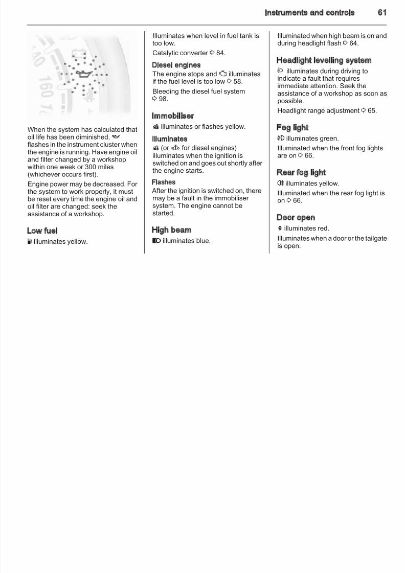
When the system has calculated thatoil life has been diminished, Iflashes in the instrument cluster when
the engine is running. Have engine oiland filter changed by a workshopwithin one week or 300 miles(whichever occurs first).
Engine power may be decreased. For the system to work properly, it mustbe reset every time the engine oil andoil filter are changed: seek theassistance of a workshop.
Low fuel
Y illuminates yellow.
too low.
Catalytic converter 3 84.
Diesel enginesThe engine stops and Z illuminates
if the fuel level is too low 3 58.Bleeding the diesel fuel system3 98.
Immobiliser
d illuminates or flashes yellow.
Illuminatesd (or A for diesel engines)illuminates when the ignition isswitched on and goes out shortly after the engine starts.
Flashes
After the ignition is switched on, theremay be a fault in the immobiliser system. The engine cannot bestarted.
High beam
P illuminates blue.
during headlight flash 3 64.
Headlight levelling system
? illuminates during driving to
indicate a fault that requiresimmediate attention. Seek theassistance of a workshop as soon apossible.
Headlight range adjustment 3 65.
Fog light
> illuminates green.
Illuminated when the front fog lightsare on 3 66.
Rear fog light
r illuminates yellow.
Illuminated when the rear fog light ison 3 66.
Door openh illuminates red.
Illuminates when a door or the tailgatis open.
62 Instruments and controls
Vehicle messages Trip computer Range
8/4/2019 Agila Owner's Manual - August 2009
http://slidepdf.com/reader/full/agila-owners-manual-august-2009 63/137
Warning chimes
When starting the engine or whiledriving
■ If the driver's seat belt is notfastened and vehicle speedexceeds approx. 9 mph.
■ When operating the turn signals.
When the vehicle is parked and/orthe driver's door is opened■ When the key is in the ignition
switch.
■ With exterior lights on (and ignitionkey removed).
Seat belt reminder 3 57.
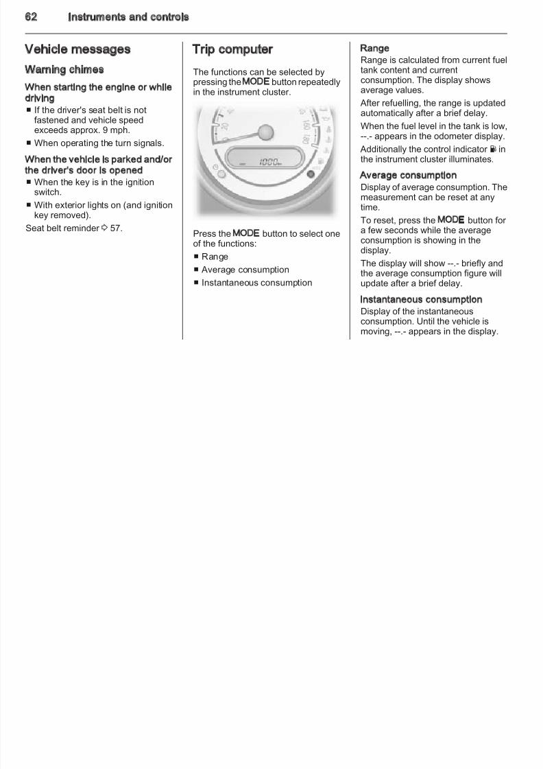
The functions can be selected bypressing the MODE button repeatedlyin the instrument cluster.
Press the MODE button to select oneof the functions:
■ Range
■ Average consumption
■ Instantaneous consumption
Range is calculated from current fueltank content and currentconsumption. The display showsaverage values.
After refuelling, the range is updatedautomatically after a brief delay.
When the fuel level in the tank is low,--.- appears in the odometer display.
Additionally the control indicator Y inthe instrument cluster illuminates.
Average consumptionDisplay of average consumption. Themeasurement can be reset at anytime.
To reset, press the MODE button for a few seconds while the averageconsumption is showing in thedisplay.
The display will show --.- briefly andthe average consumption figure willupdate after a brief delay.
Instantaneous consumptionDisplay of the instantaneousconsumption. Until the vehicle ismoving, --.- appears in the display.
Instruments and controls 6
Setting units of measuref
8/4/2019 Agila Owner's Manual - August 2009
http://slidepdf.com/reader/full/agila-owners-manual-august-2009 64/137
You can select which units of measure are to be used for fuelconsumption figures.
With the vehicle stationary and withinstantaneous consumption showingin the display, press and hold theMODE button for a few seconds totoggle between gal/h and mpg.
Interruption of power supplyIf the power supply has beeninterrupted or if the battery voltagehas dropped too low, the valuesstored in the trip computer will be lost.
64 Lighting
Lighting Exterior lighting High beam
8/4/2019 Agila Owner's Manual - August 2009
http://slidepdf.com/reader/full/agila-owners-manual-august-2009 65/137
Exterior lighting ............................ 64
Interior lighting ............................. 67
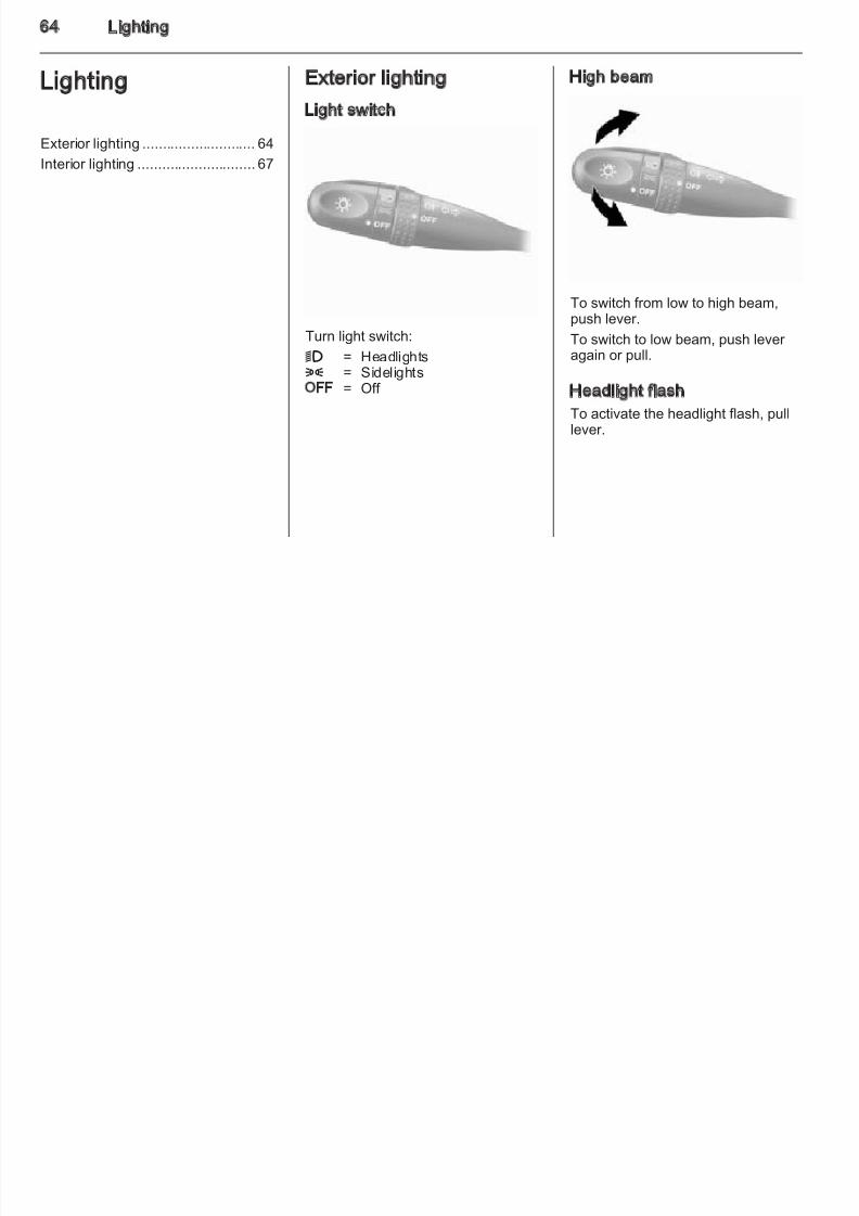
Light switch
Turn light switch:
9 = Headlights8 = SidelightsOFF = Off
To switch from low to high beam,
push lever.To switch to low beam, push lever again or pull.
Headlight flash
To activate the headlight flash, pulllever.
Lighting 6
Headlight range adjustment Headlights when driving Hazard warning flashers
8/4/2019 Agila Owner's Manual - August 2009
http://slidepdf.com/reader/full/agila-owners-manual-august-2009 66/137
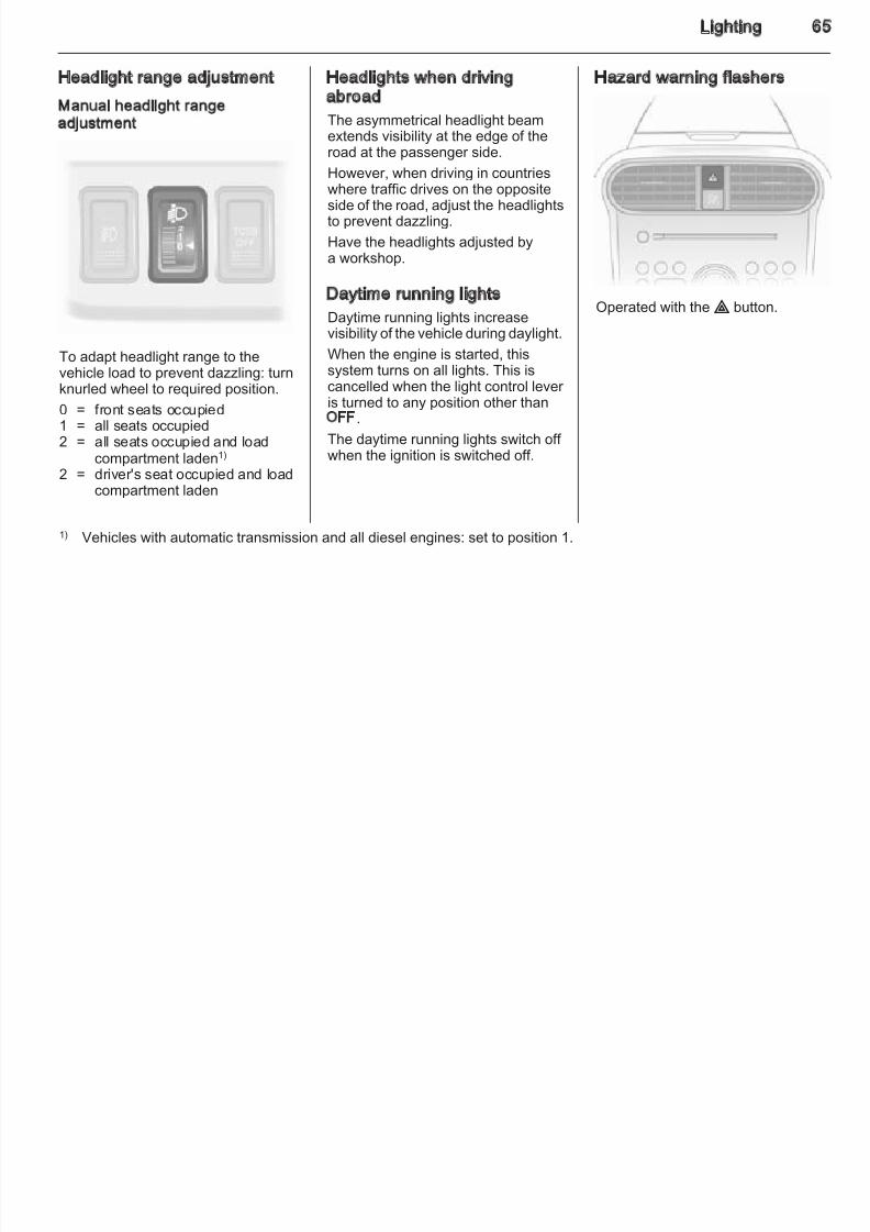
Manual headlight rangeadjustment
To adapt headlight range to thevehicle load to prevent dazzling: turnknurled wheel to required position.
0 = front seats occupied1 = all seats occupied2 = all seats occupied and load
compartment laden1)
2 = driver's seat occupied and loadcompartment laden
abroad
The asymmetrical headlight beamextends visibility at the edge of theroad at the passenger side.
However, when driving in countrieswhere traffic drives on the oppositeside of the road, adjust the headlightsto prevent dazzling.
Have the headlights adjusted bya workshop.
Daytime running lights
Daytime running lights increasevisibility of the vehicle during daylight.
When the engine is started, thissystem turns on all lights. This iscancelled when the light control lever is turned to any position other thanOFF.
The daytime running lights switch off when the ignition is switched off.
Operated with the ¨ button.
1) Vehicles with automatic transmission and all diesel engines: set to position 1.
66 Lighting
Turn and lane-change signals Front fog lights Rear fog lights
8/4/2019 Agila Owner's Manual - August 2009
http://slidepdf.com/reader/full/agila-owners-manual-august-2009 67/137
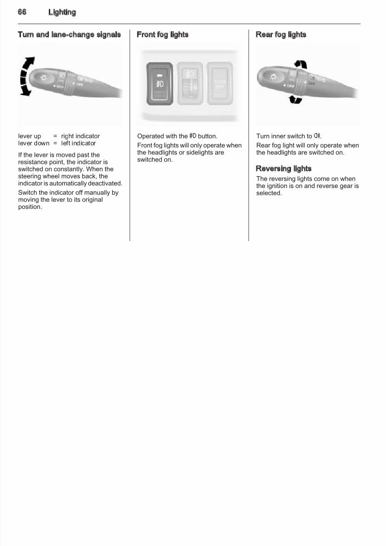
lever up = right indicator
lever down = left indicator If the lever is moved past theresistance point, the indicator isswitched on constantly. When thesteering wheel moves back, theindicator is automatically deactivated.
Switch the indicator off manually bymoving the lever to its originalposition.
Operated with the > button.
Front fog lights will only operate whenthe headlights or sidelights areswitched on.
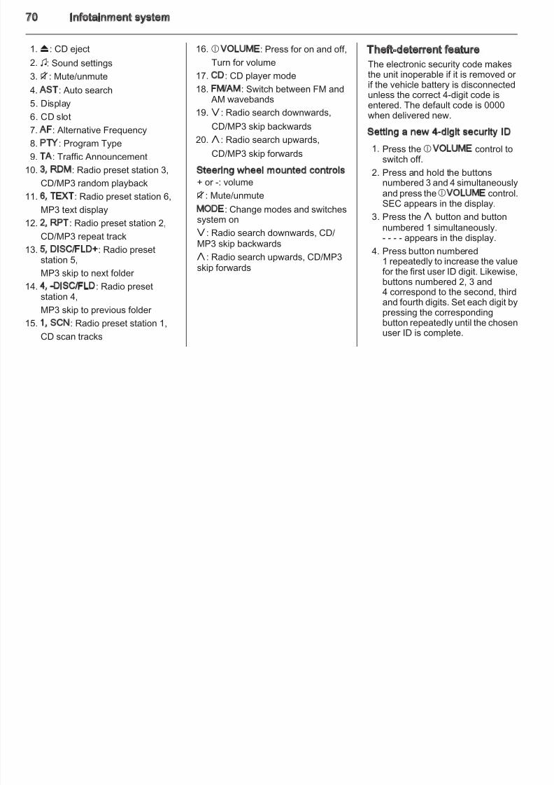
Turn inner switch to r.
Rear fog light will only operate whenthe headlights are switched on.
Reversing lights
The reversing lights come on whenthe ignition is on and reverse gear isselected.
Lighting 6
Interior lighting Caution
8/4/2019 Agila Owner's Manual - August 2009
http://slidepdf.com/reader/full/agila-owners-manual-august-2009 68/137
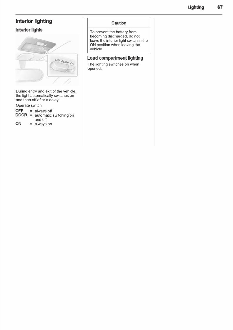
Interior lights
During entry and exit of the vehicle,the light automatically switches onand then off after a delay.
Operate switch:
OFF = always off DOOR = automatic switching on
and off ON = always on
To prevent the battery frombecoming discharged, do notleave the interior light switch in theON position when leaving thevehicle.
Load compartment lighting
The lighting switches on whenopened.
68 Infotainment system
Infotainment system
8/4/2019 Agila Owner's Manual - August 2009
http://slidepdf.com/reader/full/agila-owners-manual-august-2009 69/137
Introduction .................................. 69
Radio ........................................... 72
Audio players ............................... 74
Phone .......................................... 75
Infotainment system 6
Introduction
8/4/2019 Agila Owner's Manual - August 2009
http://slidepdf.com/reader/full/agila-owners-manual-august-2009 70/137
70 Infotainment system
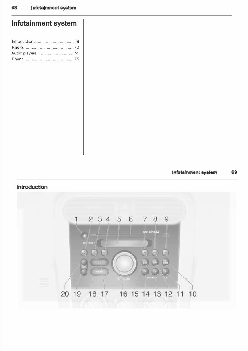
1. f: CD eject
2 6: Sound settings
16. b VOLUME: Press for on and off,
Turn for volume
Theft-deterrent feature
The electronic security code makes
8/4/2019 Agila Owner's Manual - August 2009
http://slidepdf.com/reader/full/agila-owners-manual-august-2009 71/137
2. 6: Sound settings
3. i: Mute/unmute
4. AST: Auto search
5. Display
6. CD slot
7. AF: Alternative Frequency
8. PTY: Program Type
9. TA: Traffic Announcement
10. 3, RDM: Radio preset station 3,
CD/MP3 random playback
11. 6, TEXT: Radio preset station 6,
MP3 text display12. 2, RPT: Radio preset station 2,
CD/MP3 repeat track
13. 5, DISC/FLD+: Radio presetstation 5,
MP3 skip to next folder
14. 4, -DISC/FLD: Radio presetstation 4,
MP3 skip to previous folder
15. 1, SCN: Radio preset station 1,
CD scan tracks
Turn for volume
17. CD: CD player mode
18. FM/AM: Switch between FM and AM wavebands
19. g: Radio search downwards,CD/MP3 skip backwards
20. h: Radio search upwards,
CD/MP3 skip forwards
Steering wheel mounted controls+ or -: volume
i: Mute/unmute
MODE: Change modes and switchessystem on
g: Radio search downwards, CD/
MP3 skip backwards
h: Radio search upwards, CD/MP3skip forwards
The electronic security code makesthe unit inoperable if it is removed or if the vehicle battery is disconnectedunless the correct 4-digit code isentered. The default code is 0000
when delivered new.
Setting a new 4-digit security ID
1. Press the b VOLUME control toswitch off.
2. Press and hold the buttonsnumbered 3 and 4 simultaneouslyand press theb VOLUME control.SEC appears in the display.
3. Press theh button and button
numbered 1 simultaneously.- - - - appears in the display.
4. Press button numbered1 repeatedly to increase the valuefor the first user ID digit. Likewise,buttons numbered 2, 3 and4 correspond to the second, third
and fourth digits. Set each digit bypressing the correspondingbutton repeatedly until the chosenuser ID is complete.
Infotainment system 7
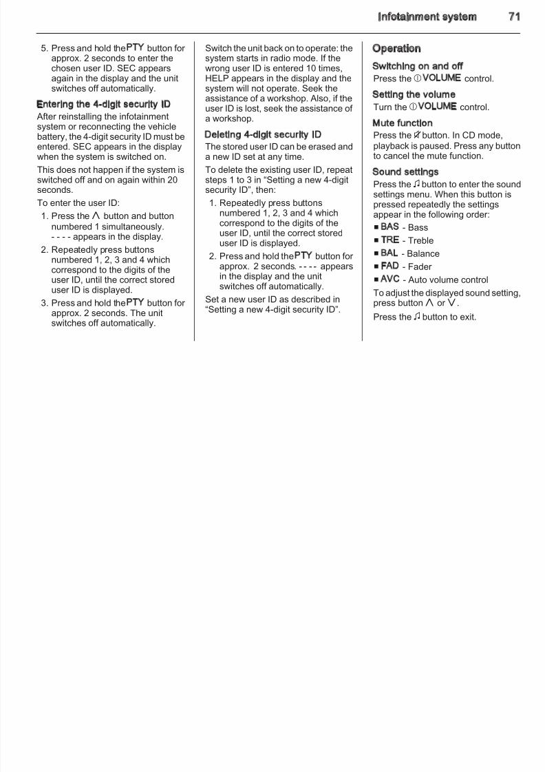
5. Press and hold the PTY button for approx. 2 seconds to enter the
Switch the unit back on to operate: thesystem starts in radio mode. If the
Operation
8/4/2019 Agila Owner's Manual - August 2009
http://slidepdf.com/reader/full/agila-owners-manual-august-2009 72/137
chosen user ID. SEC appearsagain in the display and the unitswitches off automatically.
Entering the 4-digit security ID After reinstalling the infotainmentsystem or reconnecting the vehiclebattery, the 4-digit security ID must beentered. SEC appears in the displaywhen the system is switched on.
This does not happen if the system isswitched off and on again within 20seconds.
To enter the user ID:1. Press theh button and button
numbered 1 simultaneously.- - - - appears in the display.
2. Repeatedly press buttonsnumbered 1, 2, 3 and 4 whichcorrespond to the digits of theuser ID, until the correct storeduser ID is displayed.
3. Press and hold the PTY button for approx. 2 seconds. The unitswitches off automatically.
wrong user ID is entered 10 times,HELP appears in the display and thesystem will not operate. Seek theassistance of a workshop. Also, if the
user ID is lost, seek the assistance of a workshop.
Deleting 4-digit security IDThe stored user ID can be erased anda new ID set at any time.
To delete the existing user ID, repeatsteps 1 to 3 in “Setting a new 4-digitsecurity ID”, then:
1. Repeatedly press buttonsnumbered 1, 2, 3 and 4 whichcorrespond to the digits of theuser ID, until the correct storeduser ID is displayed.
2. Press and hold the PTY button for approx. 2 seconds. - - - - appearsin the display and the unitswitches off automatically.
Set a new user ID as described in“Setting a new 4-digit security ID”.
Switching on and offPress the b VOLUME control.
Setting the volume
Turn the b VOLUME control.Mute functionPress theibutton. In CD mode,
playback is paused. Press any buttoto cancel the mute function.
Sound settingsPress the 6 button to enter the sounsettings menu. When this button is
pressed repeatedly the settingsappear in the following order:
■ BAS - Bass
■ TRE - Treble
■ BAL - Balance
■ FAD - Fader
■ AVC - Auto volume control
To adjust the displayed sound setting
press buttonh or g.
Press the 6 button to exit.
72 Infotainment system
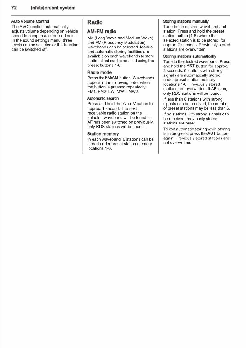
Auto Volume Control
The AVC function automaticallyRadio Storing stations manually
Tune to the desired waveband and
8/4/2019 Agila Owner's Manual - August 2009
http://slidepdf.com/reader/full/agila-owners-manual-august-2009 73/137
adjusts volume depending on vehiclespeed to compensate for road noise.In the sound settings menu, threelevels can be selected or the function
can be switched off.
AM-FM radio
AM (Long Wave and Medium Wave)and FM (Frequency Modulation)wavebands can be selected. Manual
and automatic storing facilities areavailable on each wavebands to storestations that can be recalled using thepreset buttons 1-6.
Radio modePress the FM/AM button. Wavebandsappear in the following order whenthe button is pressed repeatedly:
FM1, FM2, LW, MW1, MW2.Automatic search
Press and hold the h or gbutton for
approx. 1 second. The nextreceivable radio station on theselected waveband will be found. If AF has been switched on previously,only RDS stations will be found.
Station memoryIn each waveband, 6 stations can bestored under preset station memorylocations 1-6.
station. Press and hold the presetstation button (1-6) where theselected station is to be stored, for approx. 2 seconds. Previously stored
stations are overwritten.Storing stations automatically
Tune to the desired waveband. Pressand hold the AST button for approx.2 seconds. 6 stations with strongsignals are automatically storedunder preset station memorylocations 1-6. Previously storedstations are overwritten. If AF is on,
only RDS stations will be found.If less than 6 stations with strongsignals can be received, the number of preset stations may be less than 6.
If no stations with strong signals canbe received, previously storedstations are reset.
To exit automatic storing while storingis in progress, press the AST buttonagain. Previously stored stations arenot overwritten.
Infotainment system 7
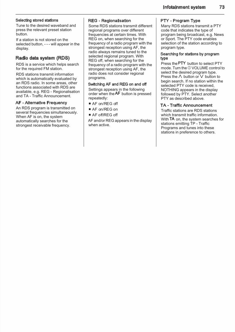
Selecting stored stations
Tune to the desired waveband andh l i
REG - RegionalisationSome RDS stations transmit different
PTY - Program TypeMany RDS stations transmit a PTY

8/4/2019 Agila Owner's Manual - August 2009
http://slidepdf.com/reader/full/agila-owners-manual-august-2009 74/137
press the relevant preset stationbutton.
If a station is not stored on theselected button, - - - will appear in the
display.
Radio data system (RDS)
RDS is a service which helps searchfor the required FM station.
RDS stations transmit informationwhich is automatically evaluated byan RDS radio. In some areas, other
functions associated with RDS areavailable, e.g. REG - Regionalisationand TA - Traffic Announcement.
AF - Alternative Frequency An RDS program is transmitted onseveral f requencies simultaneously.When AF is on, the systemautomatically searches for thestrongest receivable frequency.
regional programs over differentfrequencies at certain times. WithREG on, when searching for thefrequency of a radio program with the
strongest reception using AF, theradio always remains tuned to theselected regional program. WithREG off, when searching for thefrequency of a radio program with thestrongest reception using AF, theradio does not consider regionalprograms.
Switching AF and REG on and off
Settings appears in the followingorder when the AF button is pressedrepeatedly:
■ AF on/REG off
■ AF on/REG on
■ AF off/REG off
AF and/or REG appears in the displaywhen active.
code that indicates the type of program being broadcast, e.g. Newsor Sport. The PTY code enablesselection of the station according to
program type.
Searching for stations by programtype
Press the PTY button to select PTYmode. Turn thebVOLUME control tselect the desired program type.Press theh button or g button to
begin search. If no station within theselected PTY code is received,
NOTHING appears in the displayfollowed by PTY. Select another PTY as described above.
TA - Traffic AnnouncementTraffic stations are RDS stationswhich transmit traffic information.With TA on, the system searches fostations emitting TP - TrafficPrograms and tunes into thesestations in preference to others.
74 Infotainment system
When TA is active and a TrafficProgram is currently being received,playback is interrupted for the traffic
EON - Enhanced Other NetworksWith EON, traffic reports will be
f
Audio players
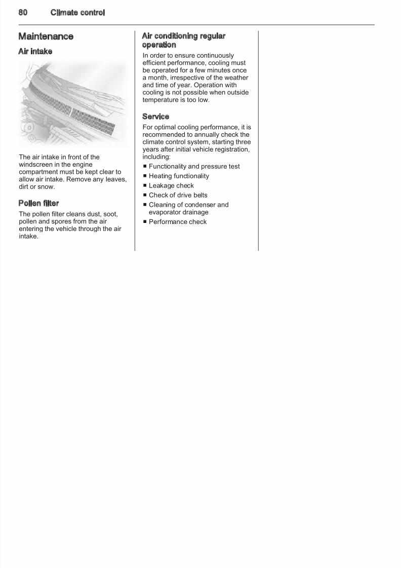
8/4/2019 Agila Owner's Manual - August 2009
http://slidepdf.com/reader/full/agila-owners-manual-august-2009 75/137
playback is interrupted for the trafficannouncement and resumes whenthe announcement ends.
Switching TA on and off
Press the TA button to switch ontraffic announcements. TA appears inthe display. When a Traffic Programis currently being received, TP alsoappears in the display. Press thebutton again to switch off.
To search for a TP station -TP SEEK, while TA is active, presstheh or g button.
If TP data is not received withinapprox. 20 seconds after TA isswitched on, TP SEEK automaticallytakes place only once. If no TP stationis received, NOTHING appears in thedisplay.
PS - Program Service NameDisplay of program name instead of
station frequency.
received, even if the set station doesnot transmit its own traffic information.When a traffic announcement ismade, the unit switches to a traffic
information station linked to EON.When EON is active, EON appears inthe display.
Radio reception
Radio reception may be disrupted bystatic, noise, distortion or loss of reception due to:
■ changes in distance from thetransmitter,
■ multi-path reception due toreflection,
■ shadowing.
CD player
The CD player can play audio CDsand, if equipped, MP3 CDs. The CDtype is automatically recognised.
Caution
Do not insert DVDs, smalldiameter single CDs and CDs withirregular shapes into the unit. Theymay become jammed or damagethe mechanism.
The system may not be able to playCD-Rs or play them properly. CD-RWdiscs cannot be played back.
CD/MP3 playbackWith a CD already inserted, press theCD button.
To insert a CD, place the audio CDinto the slot with the printed sideupwards until it automatically retracts.CD playback begins and CD INappears in the display.
Infotainment system 7
Selecting next or previous track
Press theh button to skip to the nextt k d th g b tt t ki t th
Selecting next or previous MP3 folder
If the MP3 CD consists of severalfolders press the button
Phone
8/4/2019 Agila Owner's Manual - August 2009
http://slidepdf.com/reader/full/agila-owners-manual-august-2009 76/137
track and theg button to skip to the
previous track.
Fast forwards/backwards search
Press and hold the h button to fast
forward and theg button to fastrewind through the current track.
Repeat play
Press the RPT button to play thecurrent track repeatedly. RPTappears in the display. Press buttonagain to switch off.
Random play
Press the RDM button to play thetracks on the disc in random order.RDM appears in the display. Pressbutton again to switch off.
Scan CD
Press the SCN button to play the firstfew seconds of each track on the disc.SCN appears in the display. Press
button again to switch off.
folders, press the DISC/FLD+ buttonto skip to the next folder and the -DISC/FLD button to skip to theprevious folder.
Displaying MP3 textMP3 text types appear when theTEXT button is pressed repeatedly:
■ Elapsed time
■ Folder name
■ File name
Press the TEXT button for approx.2 seconds to enable scrolling text.
Removing CDsPress thef button. The CD ejects.
Maintenance and care■ If ERROR 1 appears in the display,
the disc cannot be read.
■ If ERROR 3 appears in the display,the player has developed an
unidentified error. The inserted discmay not eject. Seek the assistanceof a workshop.
Mobile phones and CB radioequipment
Installation instructions and
operating guidelinesThe vehicle specific installationinstructions and the operatingguidelines of the mobile phone andhandsfree manufacturer must beobserved when installing andoperating a mobile telephone. Failurto do so could invalidate the vehicletype approval (EU directive 95/54/
EC).Recommendations for fault-freeoperation:
■ Professionally installed exterior antenna to obtain the maximumrange possible,
■ Maximum transmission power 10watts,
■ Installation of the phone in
a suitable spot, consider relevantNote 3 32.
76 Infotainment system
Seek advice on predeterminedinstallation points for the externalantenna or equipment holder and
Caution
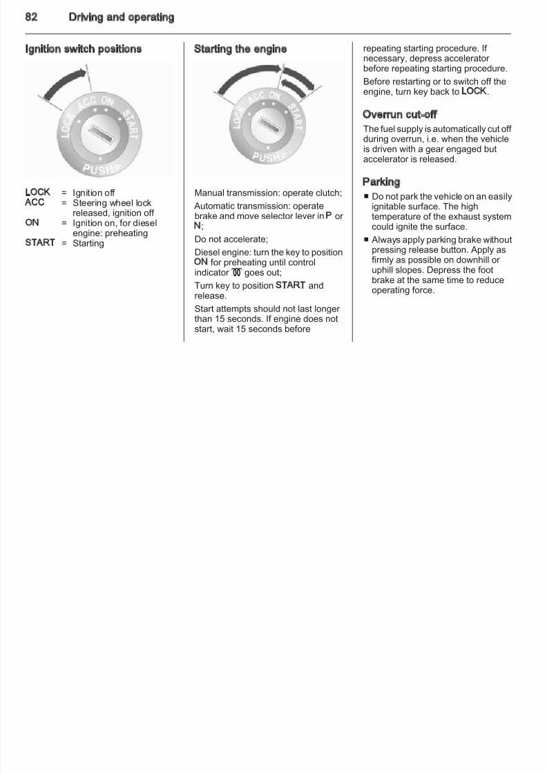
8/4/2019 Agila Owner's Manual - August 2009
http://slidepdf.com/reader/full/agila-owners-manual-august-2009 77/137
antenna or equipment holder andways of using devices witha transmission power exceeding 10watts.
Use of a handsfree attachmentwithout external antenna with mobiletelephone standards GSM900/1800/1900 and UMTS is onlypermitted if the maximumtransmission power of the mobiletelephone is 2 watts for GSM 900 or 1 watt for the other types.
For reasons of safety, do not use the
phone while driving. Even use of a handsfree set can be a distractionwhile driving.
9 Warning
Operation of radio equipment andmobile telephones which fail tomeet above mentioned mobiletelephone standards is onlypermitted using an antennalocated outside of the vehicle.
Mobile telephones and radioequipment may lead tomalfunctions in the vehicleelectronics when operated inside
the vehicle with no exterior antenna, unless the abovementioned regulations areobserved.
Climate control 7
Climate control Climate control systems Heating will not be fully effective untthe engine has reached normaloperating temperature
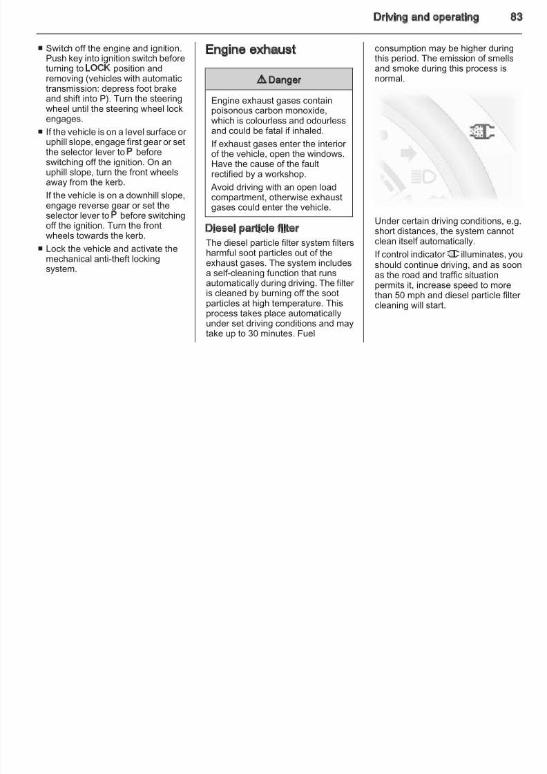
8/4/2019 Agila Owner's Manual - August 2009
http://slidepdf.com/reader/full/agila-owners-manual-august-2009 78/137
Climate control systems ............... 77
Air vents ....................................... 79
Maintenance ................................ 80
Heating and ventilation system
Controls for:
■ Temperature
■ Air distribution
■ Fan speed
Heated rear window Ü 3 26.
Temperaturered = warm
blue = cold
operating temperature.
Air distributionM = to head area via adjustable a
vents
L = to head area via centre andside air vents and to foot wel
K = to foot wellJ = to windscreen, front door
windows, side air vents and tfoot well
V = to windscreen, front door windows and side air vents
Fan speed Adjust the air flow by switching the fanto the desired speed.
78 Climate control
Air conditioning system Air recirculation system 4Operated with the 4 button.
Briefly open the windows so that hotair can disperse quickly.
■ Coolingn on
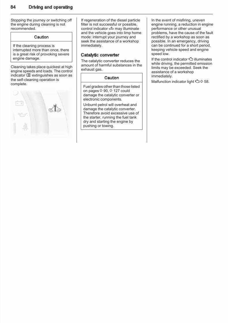
8/4/2019 Agila Owner's Manual - August 2009
http://slidepdf.com/reader/full/agila-owners-manual-august-2009 79/137
Coolingn
Operated with the n button andfunctional only when the engine andfan are running.
The air conditioning system cools anddehumidifies (dries) when outsidetemperature is a little above thefreezing point. Thereforecondensation may form and drip fromunder the vehicle.
If no cooling or drying is required,switch the cooling system off to savefuel.
9 Warning
The exchange of fresh air is
reduced in air recirculation mode.In operation without cooling the air humidity increases, so thewindows may mist up. The qualityof the passenger compartment air deteriorates, which may cause thevehicle occupants to feel drowsy.
Maximum cooling
■ Coolingn on.
■ Air recirculation system4 on.
■ Set air distribution control to M.
■ Set temperature control to coldestlevel.
■ Set fan speed to highest level.
■ Open all vents.
Climate control 7
Demisting and defrosting thewindowsV
Air vents
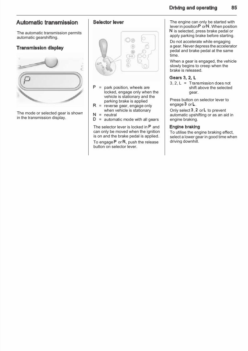
8/4/2019 Agila Owner's Manual - August 2009
http://slidepdf.com/reader/full/agila-owners-manual-august-2009 80/137
■ Set air distribution control to V.
■ Set temperature control to warmestlevel.
■ Set fan speed to highest level.
■ Switch on heated rear window Ü.
■ Open side air vents as required anddirect them towards the door windows.
Adjustable air vents
At least one air vent must be openwhile cooling is on in order to preventthe evaporator from icing up due to
lack of air movement.
The air flow can be directed asdesired by tilting the slats up, downand sideways using the centraladjuster.
Direct the air flow by tilting the slatsand turning the adjuster wheel left oright.
To open or close the vent, turn theadjuster wheel to the left or the right
Fixed air vents
Additional air vents are locatedbeneath the windscreen and door windows and in the foot wells.
80 Climate control
Maintenance Air conditioning regularoperation
I d t ti l
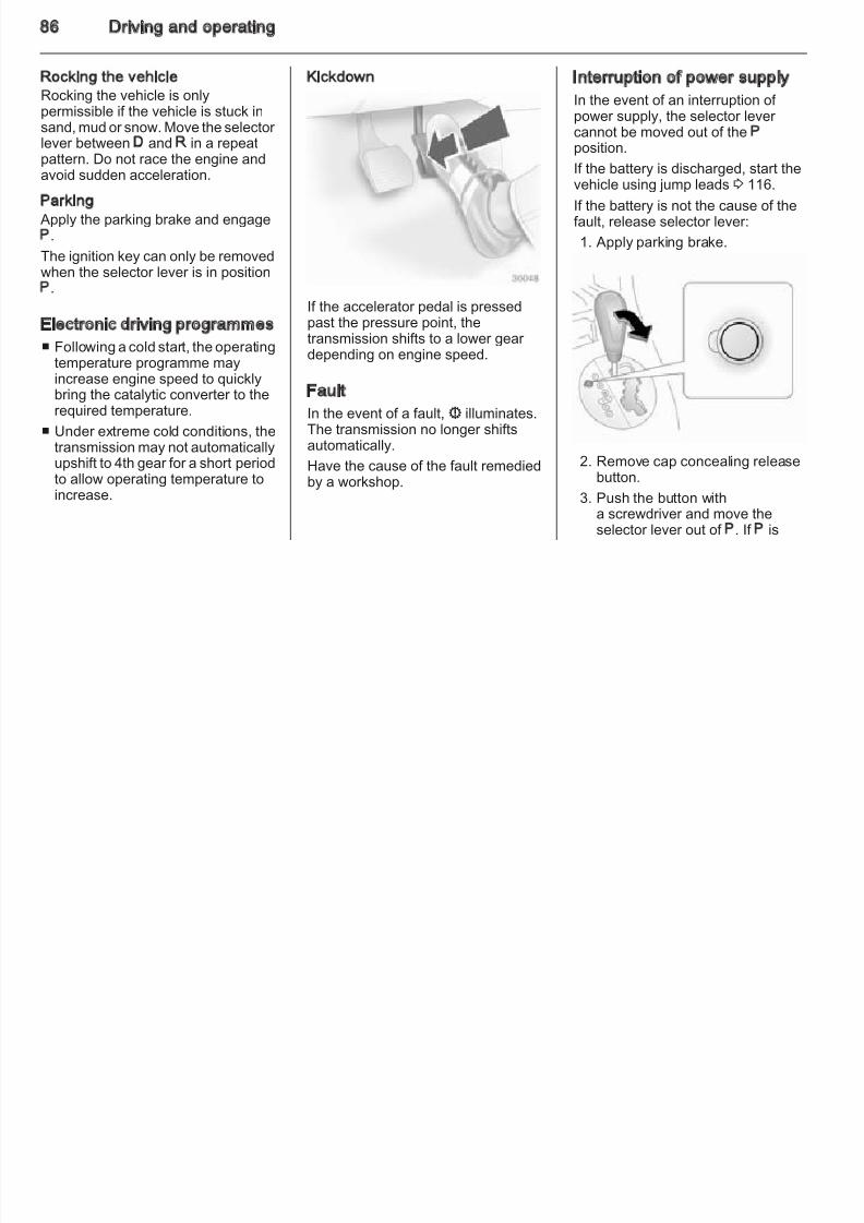
8/4/2019 Agila Owner's Manual - August 2009
http://slidepdf.com/reader/full/agila-owners-manual-august-2009 81/137
Air intake
The air intake in front of thewindscreen in the enginecompartment must be kept clear toallow air intake. Remove any leaves,dirt or snow.
Pollen filter
The pollen filter cleans dust, soot,
pollen and spores from the air entering the vehicle through the air intake.
In order to ensure continuouslyefficient performance, cooling mustbe operated for a few minutes oncea month, irrespective of the weather
and time of year. Operation withcooling is not possible when outsidetemperature is too low.
Service
For optimal cooling performance, it isrecommended to annually check theclimate control system, starting threeyears after initial vehicle registration,including:
■ Functionality and pressure test
■ Heating functionality
■ Leakage check
■ Check of drive belts
■ Cleaning of condenser andevaporator drainage
■ Performance check
Driving and operating 8
Driving andoperating
Driving hints Starting and operating
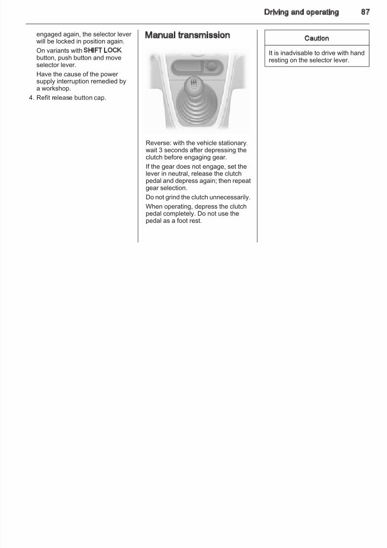
8/4/2019 Agila Owner's Manual - August 2009
http://slidepdf.com/reader/full/agila-owners-manual-august-2009 82/137
Driving hints ................................. 81
Starting and operating ................. 81
Engine exhaust ............................ 83
Automatic transmission ................ 85
Manual transmission .................... 87
Brakes .......................................... 88
Ride control systems ................... 89
Fuel .............................................. 90
Control of the vehicle
Never coast with engine notrunning
Many systems will not function in thissituation (e.g. brake servo unit, power steering). Driving in this manner isa danger to yourself and others.
PedalsTo ensure the pedal travel isuninhibited, there must be no mats inthe area of the pedals.
New vehicle running-in
Do not brake unnecessarily hard forthe first few journeys.
During the first drive, smoke mayoccur because of wax and oilevaporating off the exhaust system.Park the vehicle in the open for a while after the first drive and avoidinhaling the fumes.
Fuel and engine oil consumption mabe higher during the running-inperiod.
82 Driving and operating
Ignition switch positions Starting the engine repeating starting procedure. If necessary, depress accelerator before repeating starting procedure.
8/4/2019 Agila Owner's Manual - August 2009
http://slidepdf.com/reader/full/agila-owners-manual-august-2009 83/137
LOCK = Ignition off ACC = Steering wheel lock
released, ignition off ON = Ignition on, for diesel
engine: preheatingSTART = Starting
Manual transmission: operate clutch;
Automatic transmission: operatebrake and move selector lever in P or N;
Do not accelerate;
Diesel engine: turn the key to positionON for preheating until controlindicator ! goes out;
Turn key to position START andrelease.
Start attempts should not last longer than 15 seconds. If engine does notstart, wait 15 seconds before
Before restarting or to switch off theengine, turn key back to LOCK.
Overrun cut-offThe fuel supply is automatically cut off during overrun, i.e. when the vehicleis driven with a gear engaged butaccelerator is released.
Parking
■ Do not park the vehicle on an easily
ignitable surface. The hightemperature of the exhaust systemcould ignite the surface.
■ Always apply parking brake withoutpressing release button. Apply asfirmly as possible on downhill or uphill slopes. Depress the footbrake at the same time to reduceoperating force.
Driving and operating 8
■ Switch off the engine and ignition.Push key into ignition switch beforeturning to LOCK position and
i ( hi l i h i
Engine exhaust consumption may be higher duringthis period. The emission of smellsand smoke during this process is
l
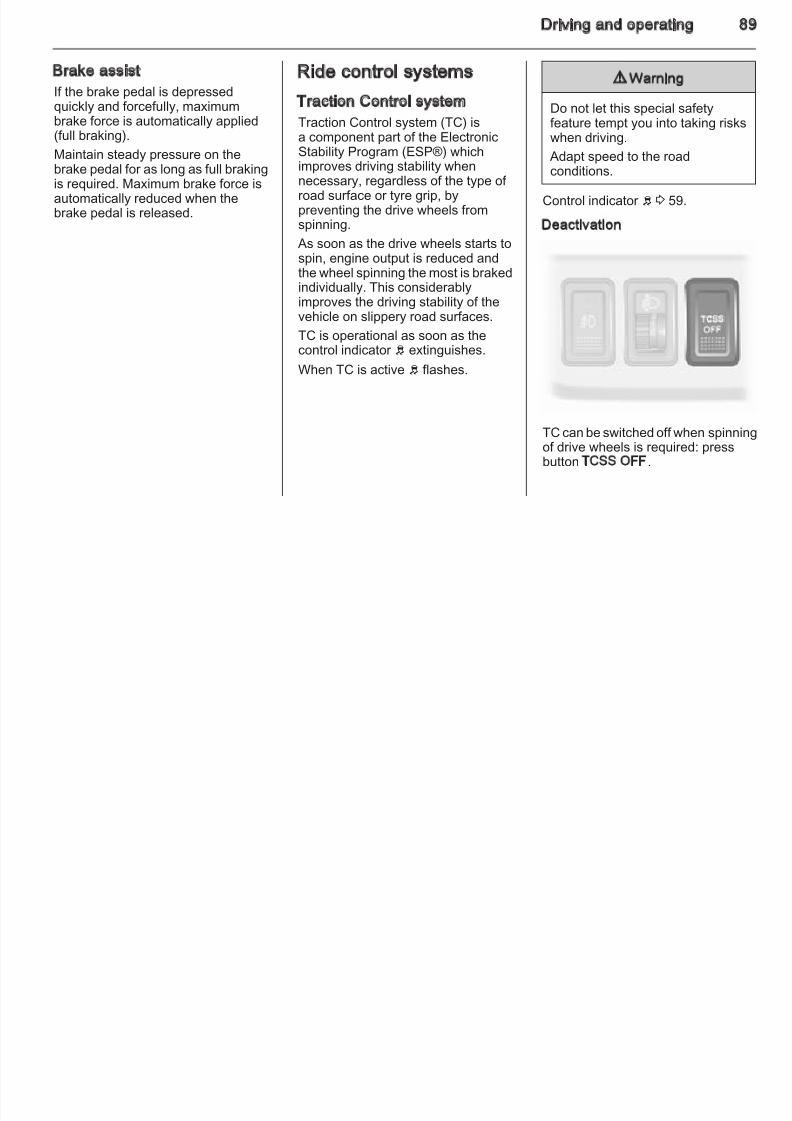
8/4/2019 Agila Owner's Manual - August 2009
http://slidepdf.com/reader/full/agila-owners-manual-august-2009 84/137
removing (vehicles with automatictransmission: depress foot brakeand shift into P). Turn the steeringwheel until the steering wheel lockengages.
■ If the vehicle is on a level surface or uphill slope, engage first gear or setthe selector lever to P beforeswitching off the ignition. On anuphill slope, turn the front wheelsaway from the kerb.
If the vehicle is on a downhill slope,
engage reverse gear or set theselector lever to P before switchingoff the ignition. Turn the frontwheels towards the kerb.
■ Lock the vehicle and activate themechanical anti-theft lockingsystem.
9 Danger
Engine exhaust gases contain
poisonous carbon monoxide,which is colourless and odourlessand could be fatal if inhaled.
If exhaust gases enter the interior of the vehicle, open the windows.Have the cause of the faultrectified by a workshop.
Avoid driving with an open loadcompartment, otherwise exhaust
gases could enter the vehicle.
Diesel particle filter
The diesel particle filter system filtersharmful soot particles out of theexhaust gases. The system includesa self-cleaning function that runsautomatically during driving. The filter is cleaned by burning off the soot
particles at high temperature. Thisprocess takes place automaticallyunder set driving conditions and maytake up to 30 minutes. Fuel
normal.
Under certain driving conditions, e.gshort distances, the system cannotclean itself automatically.
If control indicator 8 illuminates, yoshould continue driving, and as sooas the road and traffic situationpermits it, increase speed to morethan 50 mph and diesel particle filte
cleaning will start.
84 Driving and operating
Stopping the journey or switching off the engine during cleaning is notrecommended.
If regeneration of the diesel particlefilter is not successful or possible,control indicator A may illuminate
d th hi l i t li h
In the event of misfiring, unevenengine running, a reduction in engineperformance or other unusual
bl h th f th f lt
8/4/2019 Agila Owner's Manual - August 2009
http://slidepdf.com/reader/full/agila-owners-manual-august-2009 85/137
Caution
If the cleaning process isinterrupted more than once, thereis a great risk of provoking severeengine damage.
Cleaning takes place quickest at highengine speeds and loads. The controlindicator 8 extinguishes as soon as
the self-cleaning operation iscomplete.
and the vehicle goes into limp homemode: interrupt your journey andseek the assistance of a workshopimmediately.
Catalytic converter
The catalytic converter reduces theamount of harmful substances in theexhaust gas.
Caution
Fuel grades other than those listedon pages 3 90, 3 127 coulddamage the catalytic converter or electronic components.
Unburnt petrol will overheat anddamage the catalytic converter.Therefore avoid excessive use of the starter, running the fuel tankdry and starting the engine by
pushing or towing.
problems, have the cause of the faultrectified by a workshop as soon aspossible. In an emergency, drivingcan be continued for a short period,keeping vehicle speed and enginespeed low.
If the control indicator Z illuminateswhile driving, the permitted emissionlimits may be exceeded. Seek theassistance of a workshopimmediately.
Malfunction indicator light Z 3 58.
Driving and operating 8
Automatic transmission
The automatic transmission permits
Selector lever The engine can only be started withlever in position P or N. When positioN is selected, press brake pedal or apply parking brake before starting
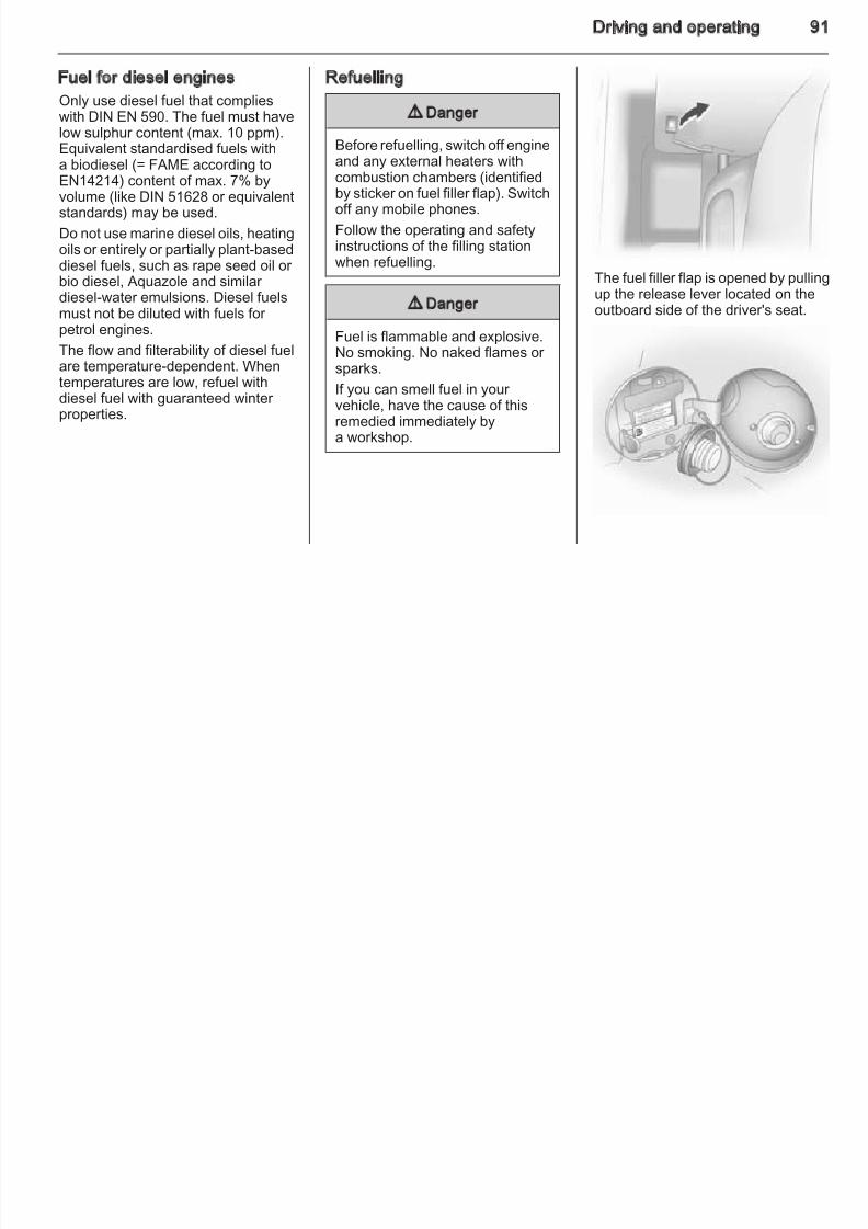
8/4/2019 Agila Owner's Manual - August 2009
http://slidepdf.com/reader/full/agila-owners-manual-august-2009 86/137
pautomatic gearshifting.
Transmission display
The mode or selected gear is shownin the transmission display.
P = park position, wheels arelocked, engage only when the
vehicle is stationary and theparking brake is applied
R = reverse gear, engage onlywhen vehicle is stationary
N = neutralD = automatic mode with all gears
The selector lever is locked in P andcan only be moved when the ignitionis on and the brake pedal is applied.
To engage P or R, push the releasebutton on selector lever.
apply parking brake before starting.
Do not accelerate while engaginga gear. Never depress the accelerato
pedal and brake pedal at the sametime.
When a gear is engaged, the vehicleslowly begins to creep when thebrake is released.
Gears 3, 2, L3, 2, L = Transmission does not
shift above the selectedgear.
Press button on selector lever toengage 3 or L.
Only select 3, 2 or L to preventautomatic upshifting or as an aid inengine braking.
Engine brakingTo utilise the engine braking effect,
select a lower gear in good time whedriving downhill.
86 Driving and operating
Rocking the vehicleRocking the vehicle is onlypermissible if the vehicle is stuck in
d d M th l t
Kickdown Interruption of power supply
In the event of an interruption of power supply, the selector lever
8/4/2019 Agila Owner's Manual - August 2009
http://slidepdf.com/reader/full/agila-owners-manual-august-2009 87/137
sand, mud or snow. Move the selector lever between D and R in a repeatpattern. Do not race the engine and
avoid sudden acceleration.Parking Apply the parking brake and engageP.
The ignition key can only be removedwhen the selector lever is in positionP.
Electronic driving programmes■ Following a cold start, the operatingtemperature programme mayincrease engine speed to quicklybring the catalytic converter to therequired temperature.
■ Under extreme cold conditions, thetransmission may not automaticallyupshift to 4th gear for a short period
to allow operating temperature toincrease.
If the accelerator pedal is pressedpast the pressure point, thetransmission shifts to a lower gear depending on engine speed.
Fault
In the event of a fault, s illuminates.The transmission no longer shiftsautomatically.
Have the cause of the fault remedied
by a workshop.
p pp ycannot be moved out of the Pposition.
If the battery is discharged, start the
vehicle using jump leads 3 116.
If the battery is not the cause of thefault, release selector lever:
1. Apply parking brake.
2. Remove cap concealing release
button.3. Push the button with
a screwdriver and move theselector lever out of P. If P is
Driving and operating 8
engaged again, the selector lever will be locked in position again.
On variants with SHIFT LOCKb tt h b tt d
Manual transmission Caution
It is inadvisable to drive with hand
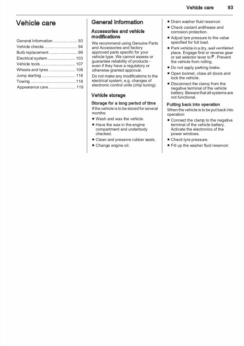
8/4/2019 Agila Owner's Manual - August 2009
http://slidepdf.com/reader/full/agila-owners-manual-august-2009 88/137
button, push button and moveselector lever.
Have the cause of the power
supply interruption remedied bya workshop.
4. Refit release button cap.
Reverse: with the vehicle stationary,
wait 3 seconds after depressing theclutch before engaging gear.
If the gear does not engage, set thelever in neutral, release the clutchpedal and depress again; then repeatgear selection.
Do not grind the clutch unnecessarily.
When operating, depress the clutch
pedal completely. Do not use thepedal as a foot rest.
resting on the selector lever.
88 Driving and operating
Brakes
The brake system comprises twoi d d t b k i it
ABS starts to regulate brake pressureas soon as a wheel shows a tendencyto lock. The vehicle remainssteerable even during hard braking
Have the cause of the fault remediedby a workshop.
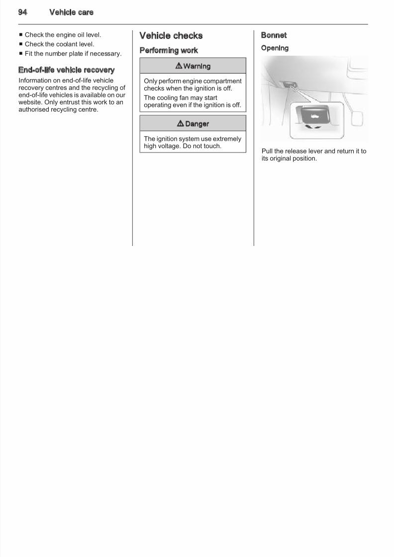
8/4/2019 Agila Owner's Manual - August 2009
http://slidepdf.com/reader/full/agila-owners-manual-august-2009 89/137
independent brake circuits.
If a brake circuit fails, the vehicle canstill be braked using the other br ake
circuit. However, braking effect isachieved only when you depress thebrake pedal firmly. You need to useconsiderably more force for this. Thebraking distance is extended. Seekthe assistance of a workshop beforecontinuing your journey.
When the engine is not running, thesupport of the brake servo unit
disappears once the brake pedal hasbeen depressed once or twice.Braking effect is not reduced, butbraking requires significantly greater force. It is especially important to bear this in mind when being towed.
Control indicator R 3 58.
Antilock brake system
Antilock brake system (ABS)prevents the wheels from locking.
steerable, even during hard braking.
ABS control is made apparentthrough a pulse in the brake pedal
and the noise of the regulationprocess.
For optimum braking, keep the brakepedal fully depressed throughout thebraking process, despite the fact thatthe pedal is pulsating. Do not reducethe pressure on the pedal.
Control indicator u 3 59.
Fault
9 Warning
If there is a fault in the ABS, thewheels may be liable to lock dueto braking that is heavier thannormal. The advantages of ABSare no longer available. Duringhard braking, the vehicle can no
longer be steered and mayswerve.
Parking brake
Always apply parking brake firmlywithout operating the release button,and apply as firmly as possible ona downhill or uphill slope.
To release the parking brake, pull thelever up slightly, press the releasebutton and fully lower the lever.
To reduce the operating forces of theparking brake, depress the foot brakeat the same time.
Control indicator R 3 58.
Driving and operating 8
Brake assist
If the brake pedal is depressedquickly and forcefully, maximumb k f i t ti ll li d
Ride control systems
Traction Control system
9 Warning
Do not let this special safety
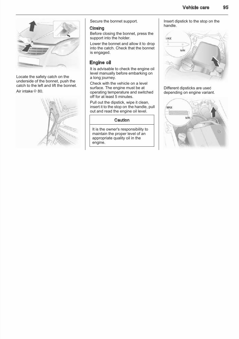
8/4/2019 Agila Owner's Manual - August 2009
http://slidepdf.com/reader/full/agila-owners-manual-august-2009 90/137
brake force is automatically applied(full braking).
Maintain steady pressure on the
brake pedal for as long as full brakingis required. Maximum brake force isautomatically reduced when thebrake pedal is released.
Traction Control system (TC) isa component part of the ElectronicStability Program (ESP®) which
improves driving stability whennecessary, regardless of the type of road surface or tyre grip, bypreventing the drive wheels fromspinning.
As soon as the drive wheels starts tospin, engine output is reduced andthe wheel spinning the most is brakedindividually. This considerably
improves the driving stability of thevehicle on slippery road surfaces.
TC is operational as soon as thecontrol indicator b extinguishes.
When TC is active b flashes.
feature tempt you into taking riskswhen driving.
Adapt speed to the road
conditions.
Control indicator b 3 59.
Deactivation
TC can be switched off when spinnin
of drive wheels is required: pressbutton TCSS OFF.
90 Driving and operating
Control indicator TCSS OFFilluminates.
TC is reactivated by pressing thebutton again
9 Warning
Do not let this special safetyf t t t i t t ki i k
Fuel
Fuel for petrol engines
O l l d d f l th t li
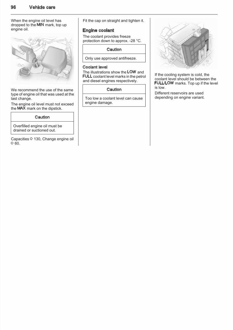
8/4/2019 Agila Owner's Manual - August 2009
http://slidepdf.com/reader/full/agila-owners-manual-august-2009 91/137
TCSS OFF button again.
Control indicator TCSS OFF 3 59.
Electronic stability programElectronic Stability Program (ESP®)improves driving stability whennecessary, regardless of the type of road surface or tyre grip. It alsoprevents the drive wheels fromspinning.
As soon as the vehicle starts toswerve (understeer/oversteer),engine output is reduced and thewheels are braked individually. Thisconsiderably improves the drivingstability of the vehicle on slippery roadsurfaces.
ESP® is operational as soon ascontr ol indicators b ESP and TCSSOFF extinguish.
When ESP® comes into actionb
flashes.
feature tempt you into taking riskswhen driving.
Adapt speed to the road
conditions.
Control indicator b 3 59.
Only use unleaded fuel that complieswith DIN EN 228.
Fuels with ethanol content greater
than 5% may only be used if thevehicle has been specificallydeveloped and approved for thesefuels.
Use fuel with the recommendedoctane rating 3 127. Use of fuel withtoo low an octane rating can reduceengine power and torque and slightlyincreases fuel consumption.
If the RON 95 label is attached to thetank flap, unleaded fuel with anoctane rating of 95 or higher must beused.
Caution
Use of fuel with too low an octanerating could lead to uncontrolled
combustion and engine damage.
Driving and operating 9
Fuel for diesel engines
Only use diesel fuel that complieswith DIN EN 590. The fuel must havelow sulphur content (max 10 ppm)
Refuelling
9 Danger
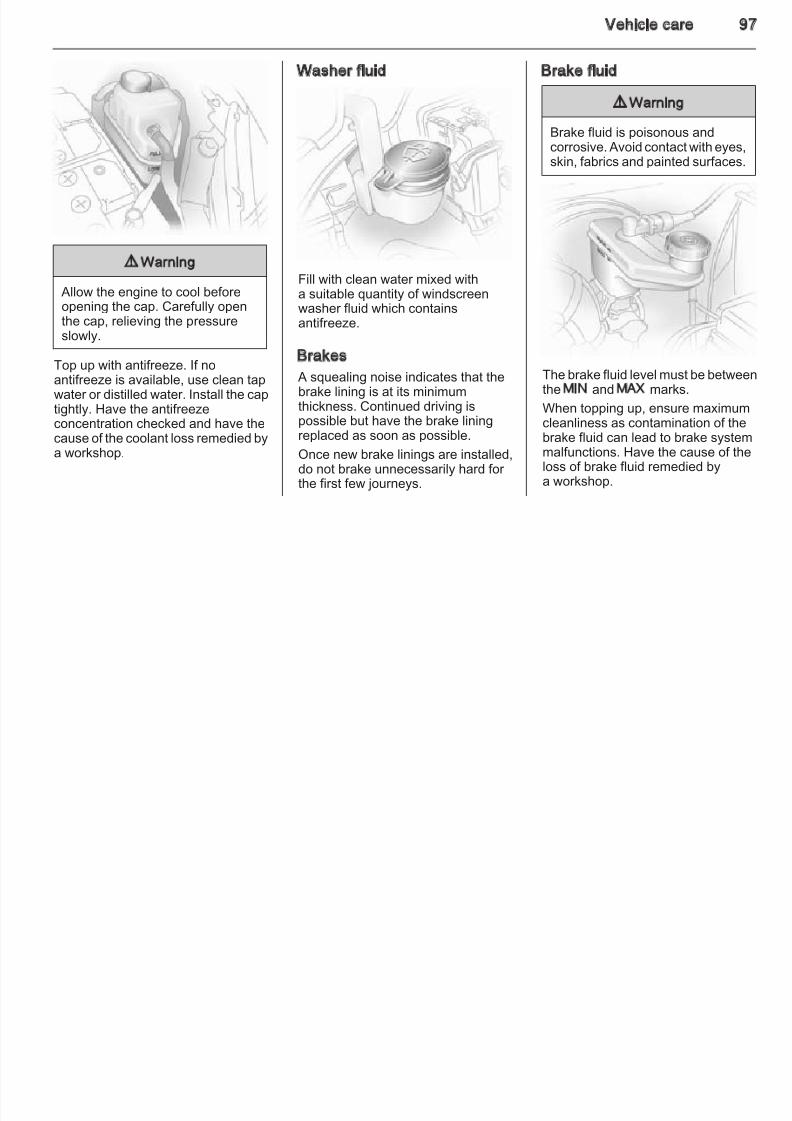
8/4/2019 Agila Owner's Manual - August 2009
http://slidepdf.com/reader/full/agila-owners-manual-august-2009 92/137
low sulphur content (max. 10 ppm).Equivalent standardised fuels witha biodiesel (= FAME according to
EN14214) content of max. 7% byvolume (like DIN 51628 or equivalentstandards) may be used.
Do not use marine diesel oils, heatingoils or entirely or partially plant-baseddiesel fuels, such as rape seed oil or bio diesel, Aquazole and similar diesel-water emulsions. Diesel fuelsmust not be diluted with fuels for
petrol engines.The flow and filterability of diesel fuelare temperature-dependent. Whentemperatures are low, refuel withdiesel fuel with guaranteed winter properties.
Before refuelling, switch off engineand any external heaters withcombustion chambers (identifiedby sticker on fuel filler flap). Switchoff any mobile phones.
Follow the operating and safetyinstructions of the filling stationwhen refuelling.
9 Danger
Fuel is flammable and explosive.No smoking. No naked flames or sparks.
If you can smell fuel in your vehicle, have the cause of thisremedied immediately bya workshop.
The fuel filler flap is opened by pullinup the release lever located on theoutboard side of the driver's seat.
92 Driving and operating
To open fuel filler cap: turn itanticlockwise.
Caution
The figures given must not be takenas a guarantee for the actual fuelconsumption of a particular vehicle.Furthermore, fuel consumption is
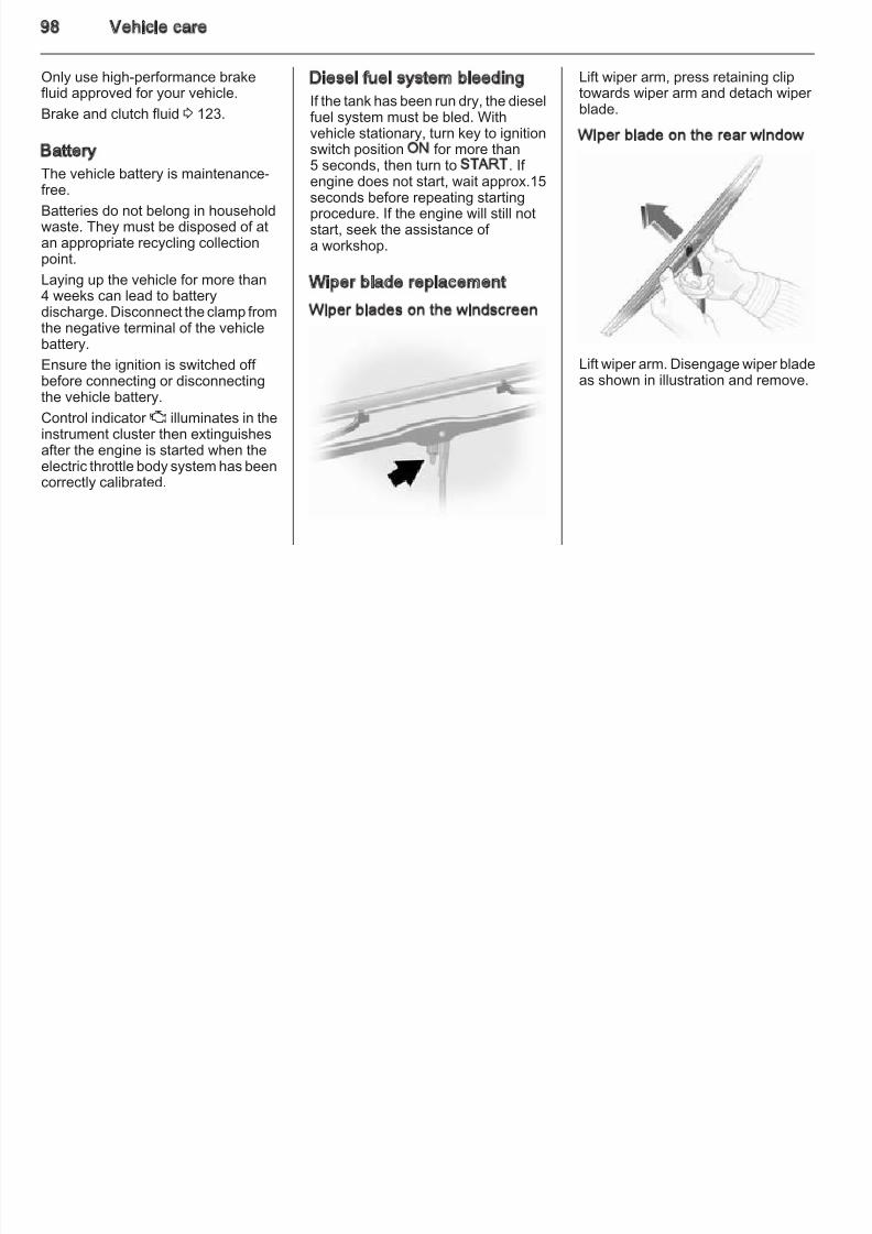
8/4/2019 Agila Owner's Manual - August 2009
http://slidepdf.com/reader/full/agila-owners-manual-august-2009 93/137
Wipe off any overflowing fuelimmediately.
Fuel filler capOnly a genuine fuel filler cap providesfull functionality. Diesel-enginedvehicles have special fuel filler caps.
Fuel consumption - CO2-
Emissions
The determination of fuelconsumption is regulated byEuropean directive 80/1268/EEC(latest edition 2004/3/EC).
The directive is oriented to actualdriving practices: Urban driving israted at approx. 1/3 and extra urban
driving with approx. 2/3. Cold starts
and acceleration phases are alsotaken into consideration.
The specification of CO2 emission is
also a constituent of the directive.
dependent on personal driving styleas well as road and traffic conditions.
All values are based on the EU basemodel with standard equipment.
The calculation of fuel consumptiontakes account of the vehicle's kerbweight, ascertained in accordancewith the regulations. Optionalequipment may result in slightlyhigher fuel consumption and CO2
emission levels and a lower maximumspeed.
Fuel consumption, CO2 emissions
3 128.
Vehicle care 9
Vehicle care General Information
Accessories and vehicle
■ Drain washer fluid reservoir.
■ Check coolant antifreeze andcorrosion protection.
■ Adjust tyre pressure to the value
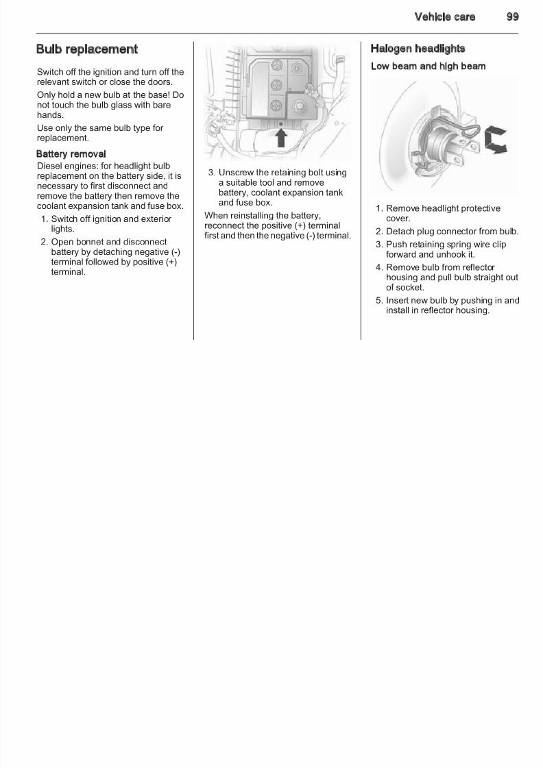
8/4/2019 Agila Owner's Manual - August 2009
http://slidepdf.com/reader/full/agila-owners-manual-august-2009 94/137
General Information ..................... 93
Vehicle checks ............................. 94
Bulb replacement ......................... 99Electrical system ........................ 103
Vehicle tools .............................. 107
Wheels and tyres ....................... 108
Jump starting ............................. 116
Towing ....................................... 118
Appearance care ....................... 119
modifications
We recommend using Genuine Partsand Accessories and factory
approved parts specific for your vehicle type. We cannot assess or guarantee reliability of products -even if they have a regulatory or otherwise granted approval.
Do not make any modifications to theelectrical system, e.g. changes of electronic control units (chip tuning).
Vehicle storage
Storage for a long period of timeIf the vehicle is to be stored for severalmonths:
■ Wash and wax the vehicle.
■ Have the wax in the enginecompartment and underbodychecked.
■ Clean and preserve rubber seals.
■ Change engine oil.
■ Adjust tyre pressure to the valuespecified for full load.
■ Park vehicle in a dry, well ventilate
place. Engage first or reverse geaor set selector lever to P. Preventthe vehicle from rolling.
■ Do not apply parking brake.
■ Open bonnet, close all doors andlock the vehicle.
■ Disconnect the clamp from thenegative terminal of the vehiclebattery. Beware that all systems arnot functional.
Putting back into operationWhen the vehicle is to be put back intoperation:
■ Connect the clamp to the negativeterminal of the vehicle battery. Activate the electronics of thepower windows.
■ Check tyre pressure.
■ Fill up the washer fluid reservoir.
94 Vehicle care
■ Check the engine oil level.
■ Check the coolant level.
■ Fit the number plate if necessary.
Vehicle checks
Performing work
Bonnet
Opening
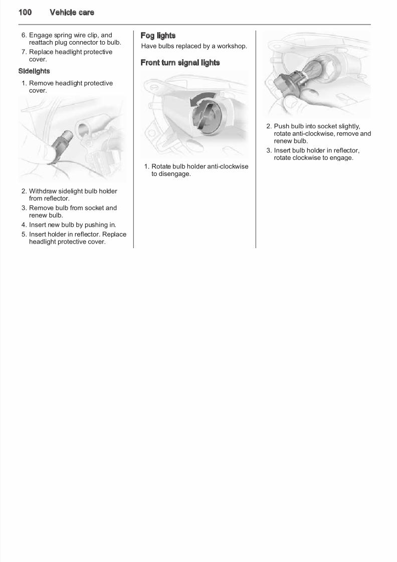
8/4/2019 Agila Owner's Manual - August 2009
http://slidepdf.com/reader/full/agila-owners-manual-august-2009 95/137
End-of-life vehicle recovery
Information on end-of-life vehiclerecovery centres and the recycling of end-of-life vehicles is available on our website. Only entrust this work to anauthorised recycling centre.
9 Warning
Only perform engine compartmentchecks when the ignition is off.
The cooling fan may startoperating even if the ignition is off.
9 Danger
The ignition system use extremelyhigh voltage. Do not touch.
Pull the release lever and return it toits original position.
Vehicle care 9
Secure the bonnet support.
ClosingBefore closing the bonnet, press thesupport into the holder
Insert dipstick to the stop on thehandle.
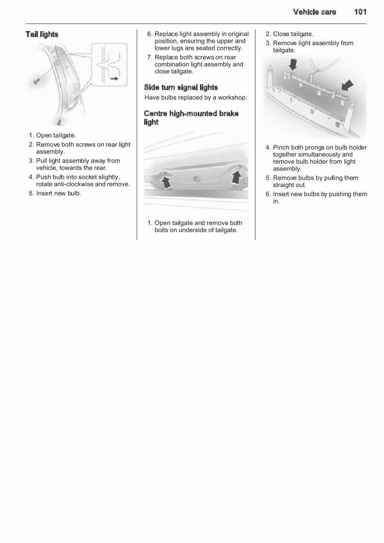
8/4/2019 Agila Owner's Manual - August 2009
http://slidepdf.com/reader/full/agila-owners-manual-august-2009 96/137
Locate the safety catch on theunderside of the bonnet, push thecatch to the left and lift the bonnet.
Air intake3
80.
support into the holder.
Lower the bonnet and allow it to dropinto the catch. Check that the bonnet
is engaged.
Engine oil
It is advisable to check the engine oillevel manually before embarking ona long journey.
Check with the vehicle on a levelsurface. The engine must be at
operating temperature and switchedoff for at least 5 minutes.
Pull out the dipstick, wipe it clean,insert it to the stop on the handle, pullout and read the engine oil level.
Caution
It is the owner's responsibility to
maintain the proper level of anappropriate quality oil in theengine.
Different dipsticks are used
depending on engine variant.
96 Vehicle care
When the engine oil level hasdropped to the MIN mark, top upengine oil.
Fit the cap on straight and tighten it.
Engine coolant
The coolant provides freeze
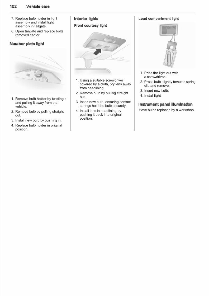
8/4/2019 Agila Owner's Manual - August 2009
http://slidepdf.com/reader/full/agila-owners-manual-august-2009 97/137
We recommend the use of the sametype of engine oil that was used at thelast change.
The engine oil level must not exceedthe MAX mark on the dipstick.
Caution
Overfilled engine oil must be
drained or suctioned out.
Capacities 3 130, Change engine oil3 60.
The coolant provides freezeprotection down to approx. -28 °C.
Caution
Only use approved antifreeze.
Coolant levelThe illustrations show the LOW andFULL coolant level marks in the petroland diesel engines respectively.
Caution
Too low a coolant level can causeengine damage.
If the cooling system is cold, thecoolant level should be between theFULL/LOW marks. Top up if the levelis low.
Different reservoirs are useddepending on engine variant.
Vehicle care 9
Washer fluid Brake fluid
9 Warning
B k fl id i i d
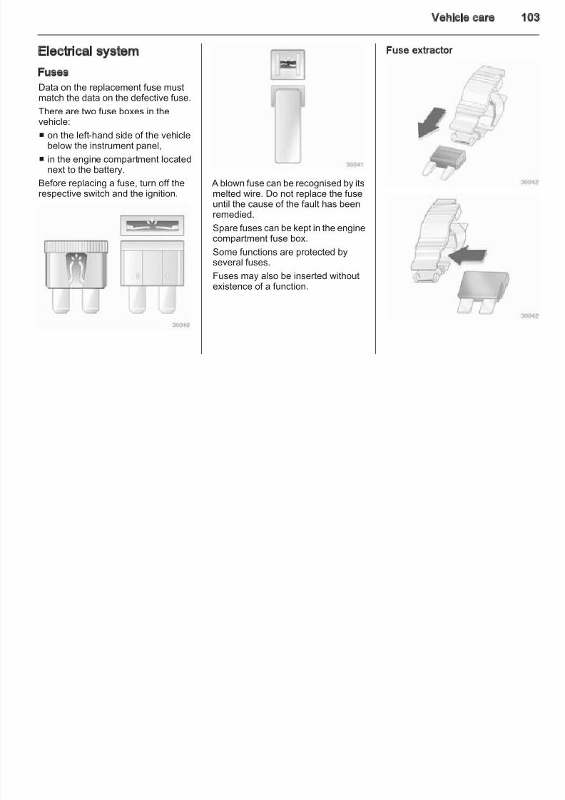
8/4/2019 Agila Owner's Manual - August 2009
http://slidepdf.com/reader/full/agila-owners-manual-august-2009 98/137
9 Warning
Allow the engine to cool before
opening the cap. Carefully openthe cap, relieving the pressureslowly.
Top up with antifreeze. If noantifreeze is available, use clean tapwater or distilled water. Install the captightly. Have the antifreezeconcentration checked and have thecause of the coolant loss remedied bya workshop.
Fill with clean water mixed witha suitable quantity of windscreen
washer fluid which containsantifreeze.
Brakes
A squealing noise indicates that thebrake lining is at its minimumthickness. Continued driving ispossible but have the brake liningreplaced as soon as possible.
Once new brake linings are installed,do not brake unnecessarily hard for the first few journeys.
Brake fluid is poisonous andcorrosive. Avoid contact with eyes,skin, fabrics and painted surfaces.
The brake fluid level must be betweethe MIN and MAX marks.
When topping up, ensure maximumcleanliness as contamination of thebrake fluid can lead to brake systemmalfunctions. Have the cause of theloss of brake fluid remedied bya workshop.
98 Vehicle care
Only use high-performance brakefluid approved for your vehicle.
Brake and clutch fluid 3 123.
Diesel fuel system bleeding
If the tank has been run dry, the dieselfuel system must be bled. Withvehicle stationary, turn key to ignition
Lift wiper arm, press retaining cliptowards wiper arm and detach wiper blade.
Wiper blade on the rear window
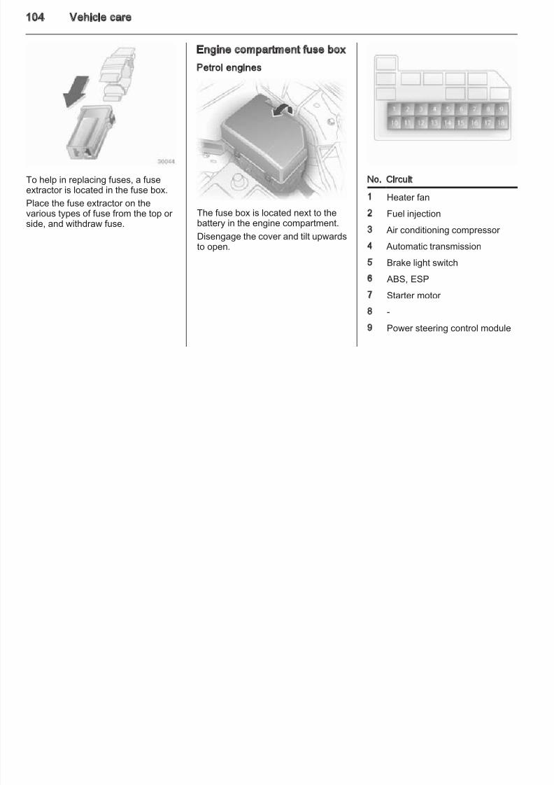
8/4/2019 Agila Owner's Manual - August 2009
http://slidepdf.com/reader/full/agila-owners-manual-august-2009 99/137
Battery
The vehicle battery is maintenance-
free.Batteries do not belong in householdwaste. They must be disposed of atan appropriate recycling collectionpoint.
Laying up the vehicle for more than4 weeks can lead to batterydischarge. Disconnect the clamp fromthe negative terminal of the vehicle
battery.
Ensure the ignition is switched off before connecting or disconnectingthe vehicle battery.
Control indicator Z illuminates in theinstrument cluster then extinguishesafter the engine is started when theelectric throttle body system has beencorrectly calibr ated.
switch position ON for more than5 seconds, then turn to START. If
engine does not start, wait approx.15seconds before repeating startingprocedure. If the engine will still notstart, seek the assistance of a workshop.
Wiper blade replacement
Wiper blades on the windscreen
Lift wiper arm. Disengage wiper bladeas shown in illustration and remove.
Vehicle care 9
Bulb replacement
Switch off the ignition and turn off therelevant switch or close the doors.
Halogen headlights
Low beam and high beam
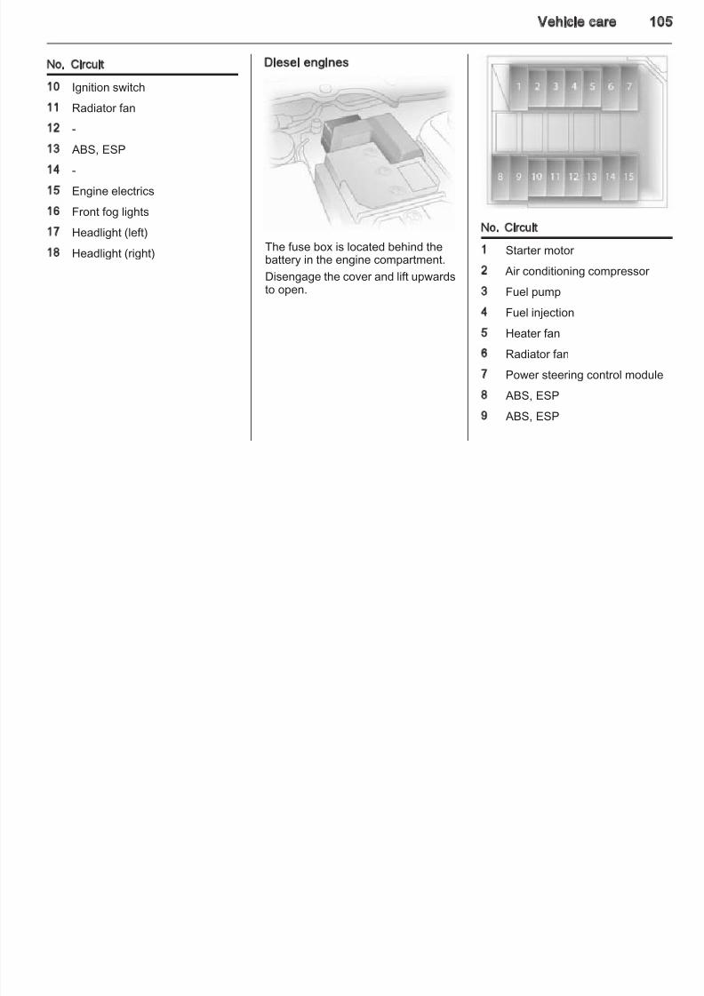
8/4/2019 Agila Owner's Manual - August 2009
http://slidepdf.com/reader/full/agila-owners-manual-august-2009 100/137
Only hold a new bulb at the base! Donot touch the bulb glass with bare
hands.Use only the same bulb type for replacement.
Battery removalDiesel engines: for headlight bulbreplacement on the battery side, it isnecessary to first disconnect andremove the battery then remove thecoolant expansion tank and fuse box.
1. Switch off ignition and exterior lights.
2. Open bonnet and disconnectbattery by detaching negative (-)terminal followed by positive (+)terminal.
3. Unscrew the retaining bolt usinga suitable tool and removebattery, coolant expansion tankand fuse box.
When reinstalling the battery,reconnect the positive (+) terminalfirst and then the negative (-) terminal.
1. Remove headlight protectivecover.
2. Detach plug connector from bulb
3. Push retaining spring wire clipforward and unhook it.
4. Remove bulb from reflector housing and pull bulb straight ouof socket.
5. Insert new bulb by pushing in aninstall in reflector housing.
100 Vehicle care
6. Engage spring wire clip, andreattach plug connector to bulb.
7. Replace headlight protectivecover.
Fog lights
Have bulbs replaced by a workshop.
Front turn signal lights
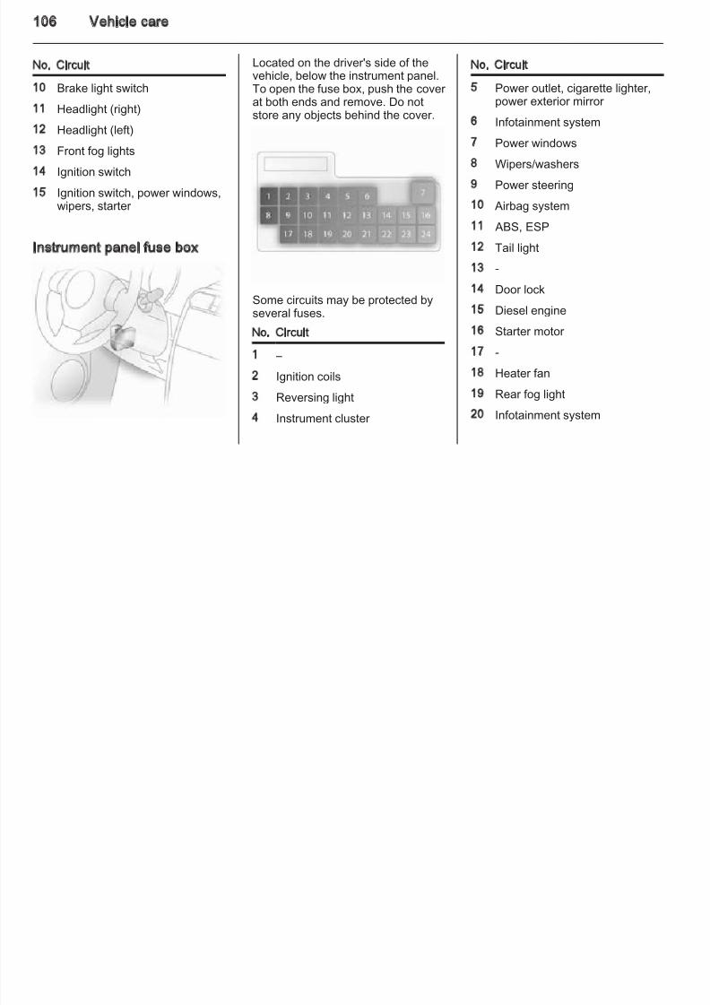
8/4/2019 Agila Owner's Manual - August 2009
http://slidepdf.com/reader/full/agila-owners-manual-august-2009 101/137
Sidelights
1. Remove headlight protectivecover.
2. Withdraw sidelight bulb holder from reflector.
3. Remove bulb from socket andrenew bulb.
4. Insert new bulb by pushing in.5. Insert holder in reflector. Replace
headlight protective cover.
1. Rotate bulb holder anti-clockwiseto disengage.
2. Push bulb into socket slightly,rotate anti-clockwise, remove andrenew bulb.
3. Insert bulb holder in reflector,
rotate clockwise to engage.
Vehicle care 10
Tail lights 6. Replace light assembly in originalposition, ensuring the upper andlower lugs are seated correctly.
7. Replace both screws on rear combination light assembly and
2. Close tailgate.
3. Remove light assembly fromtailgate.
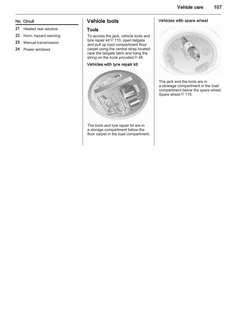
8/4/2019 Agila Owner's Manual - August 2009
http://slidepdf.com/reader/full/agila-owners-manual-august-2009 102/137
1. Open tailgate.
2. Remove both screws on rear light
assembly.
3. Pull light assembly away fromvehicle, towards the rear.
4. Push bulb into socket slightly,rotate anti-clockwise and remove.
5. Insert new bulb.
combination light assembly andclose tailgate.
Side turn signal lights
Have bulbs replaced by a workshop.
Centre high-mounted brakelight
1. Open tailgate and remove bothbolts on underside of tailgate.
4. Pinch both prongs on bulb holdetogether simultaneously andremove bulb holder from lightassembly.
5. Remove bulbs by pulling themstraight out.
6. Insert new bulbs by pushing themin.
102 Vehicle care
7. Replace bulb holder in lightassembly and install lightassembly in tailgate.
8. Open tailgate and replace boltsremoved earlier
Interior lights
Front courtesy light
Load compartment light
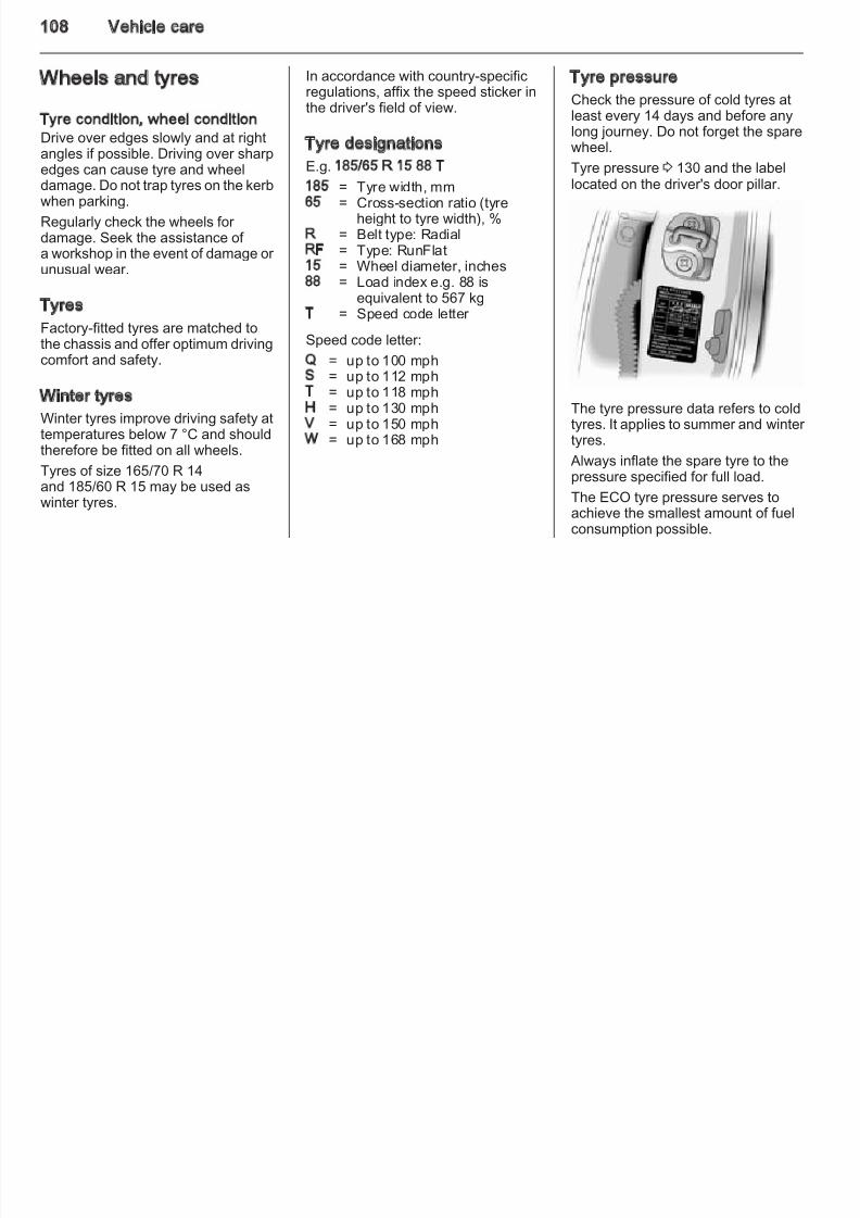
8/4/2019 Agila Owner's Manual - August 2009
http://slidepdf.com/reader/full/agila-owners-manual-august-2009 103/137
removed earlier.
Number plate light
1. Remove bulb holder by twisting itand pulling it away from thevehicle.
2. Remove bulb by pulling straightout.
3. Install new bulb by pushing in.
4. Replace bulb holder in originalposition.
1. Using a suitable screwdriver covered by a cloth, pry lens awayfrom headlining.
2. Remove bulb by pulling straightout.
3. Insert new bulb, ensuring contactsprings hold the bulb securely.
4. Install lens in headlining bypushing it back into original
position.
1. Prise the light out witha screwdriver.
2. Press bulb slightly towards springclip and remove.
3. Insert new bulb.
4. Install light.
Instrument panel illumination
Have bulbs replaced by a workshop.
Vehicle care 10
Electrical system
Fuses
Data on the replacement fuse mustmatch the data on the defective fuse
Fuse extractor
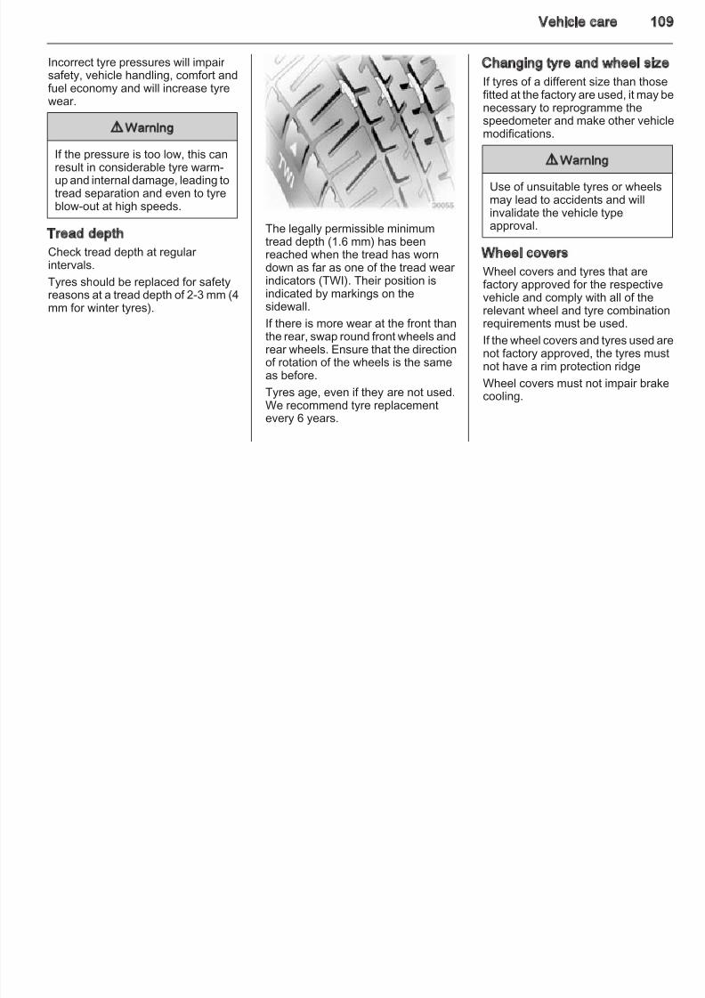
8/4/2019 Agila Owner's Manual - August 2009
http://slidepdf.com/reader/full/agila-owners-manual-august-2009 104/137
match the data on the defective fuse.
There are two fuse boxes in the
vehicle:■ on the left-hand side of the vehicle
below the instrument panel,
■ in the engine compartment locatednext to the battery.
Before replacing a fuse, turn off therespective switch and the ignition.
A blown fuse can be recognised by itsmelted wire. Do not replace the fuseuntil the cause of the fault has beenremedied.
Spare fuses can be kept in the enginecompartment fuse box.
Some functions are protected byseveral fuses.
Fuses may also be inserted withoutexistence of a function.
104 Vehicle care
Engine compartment fuse box
Petrol engines
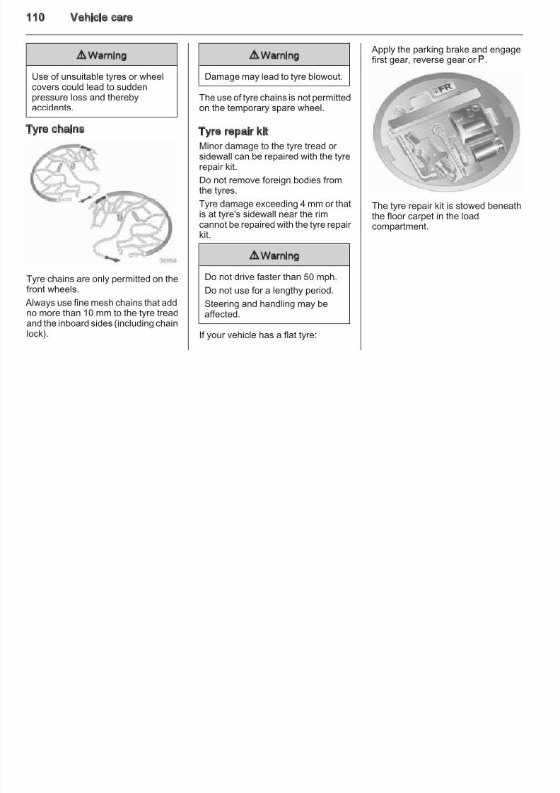
8/4/2019 Agila Owner's Manual - August 2009
http://slidepdf.com/reader/full/agila-owners-manual-august-2009 105/137
To help in replacing fuses, a fuseextractor is located in the fuse box.
Place the fuse extractor on the
various types of fuse from the top or side, and withdraw fuse.
The fuse box is located next to thebattery in the engine compartment.
Disengage the cover and tilt upwardsto open.
No. Circuit
1 Heater fan
2 Fuel injection3 Air conditioning compressor
4 Automatic transmission
5 Brake light switch
6 ABS, ESP
7 Starter motor
8 -9 Power steering control module
Vehicle care 10
No. Circuit
10 Ignition switch
11 Radiator fan
Diesel engines
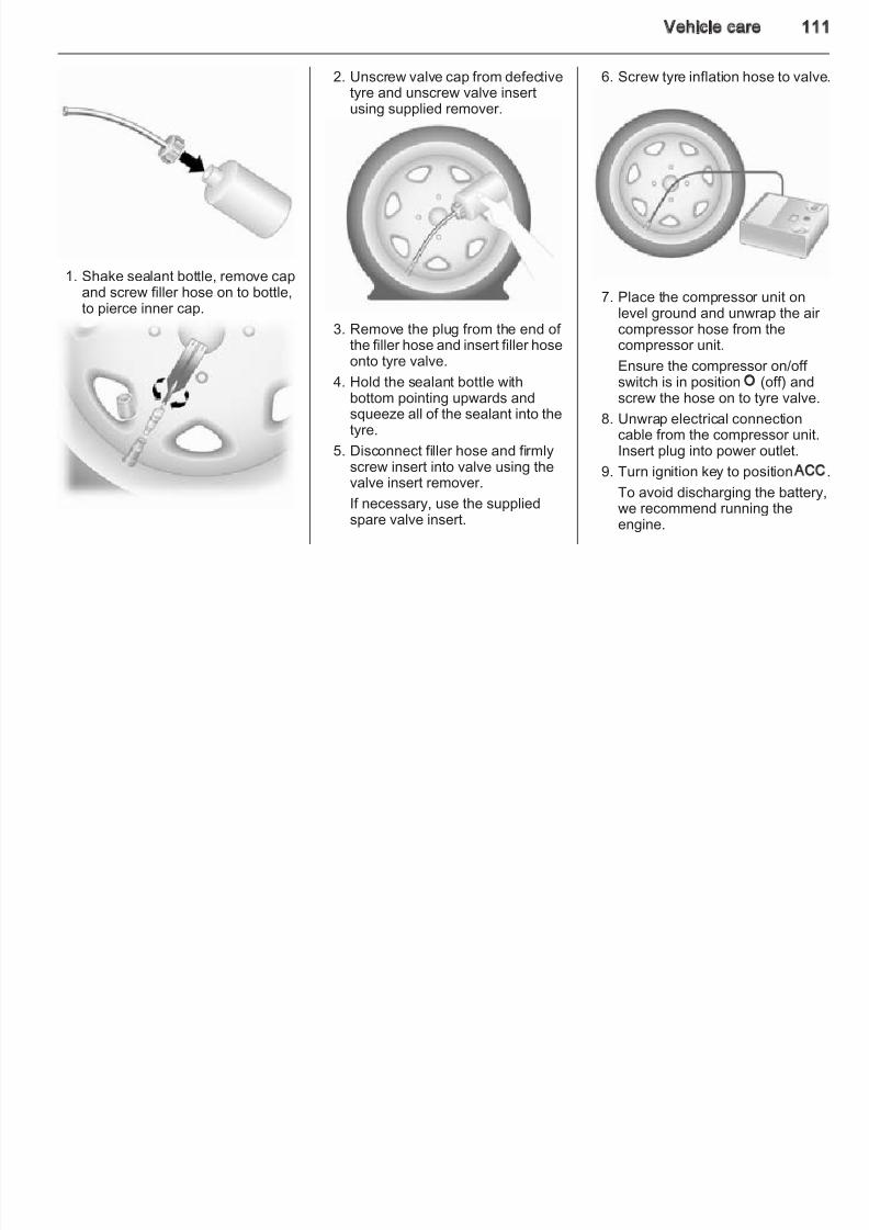
8/4/2019 Agila Owner's Manual - August 2009
http://slidepdf.com/reader/full/agila-owners-manual-august-2009 106/137
12 -
13 ABS, ESP14 -
15 Engine electrics
16 Front fog lights
17 Headlight (left)
18 Headlight (right)The fuse box is located behind thebattery in the engine compartment.
Disengage the cover and lift upwardsto open.
No. Circuit
1 Starter motor
2 Air conditioning compressor 3 Fuel pump
4 Fuel injection
5 Heater fan
6 Radiator fan
7 Power steering control module
8 ABS, ESP9 ABS, ESP
106 Vehicle care
No. Circuit
10 Brake light switch
11 Headlight (right)
Located on the driver's side of thevehicle, below the instrument panel.To open the fuse box, push the cover at both ends and remove. Do notstore any objects behind the cover.
No. Circuit
5 Power outlet, cigarette lighter,power exterior mirror
Infotainment system
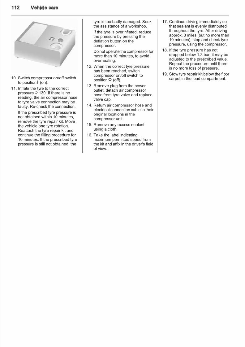
8/4/2019 Agila Owner's Manual - August 2009
http://slidepdf.com/reader/full/agila-owners-manual-august-2009 107/137
12 Headlight (left)
13 Front fog lights14 Ignition switch
15 Ignition switch, power windows,wipers, starter
Instrument panel fuse box
Some circuits may be protected byseveral fuses.
No. Circuit
1 –
2 Ignition coils
3 Reversing light4 Instrument cluster
6 Infotainment system
7 Power windows
8 Wipers/washers
9 Power steering
10 Airbag system
11 ABS, ESP
12 Tail light
13 -
14 Door lock
15 Diesel engine
16 Starter motor
17 -
18 Heater fan
19 Rear fog light
20 Infotainment system
Vehicle care 10
No. Circuit
21 Heated rear window
22 Horn, hazard warning
M l t i i
Vehicle tools
Tools
To access the jack, vehicle tools andtyre repair kit 3 110, open tailgate
Vehicles with spare wheel
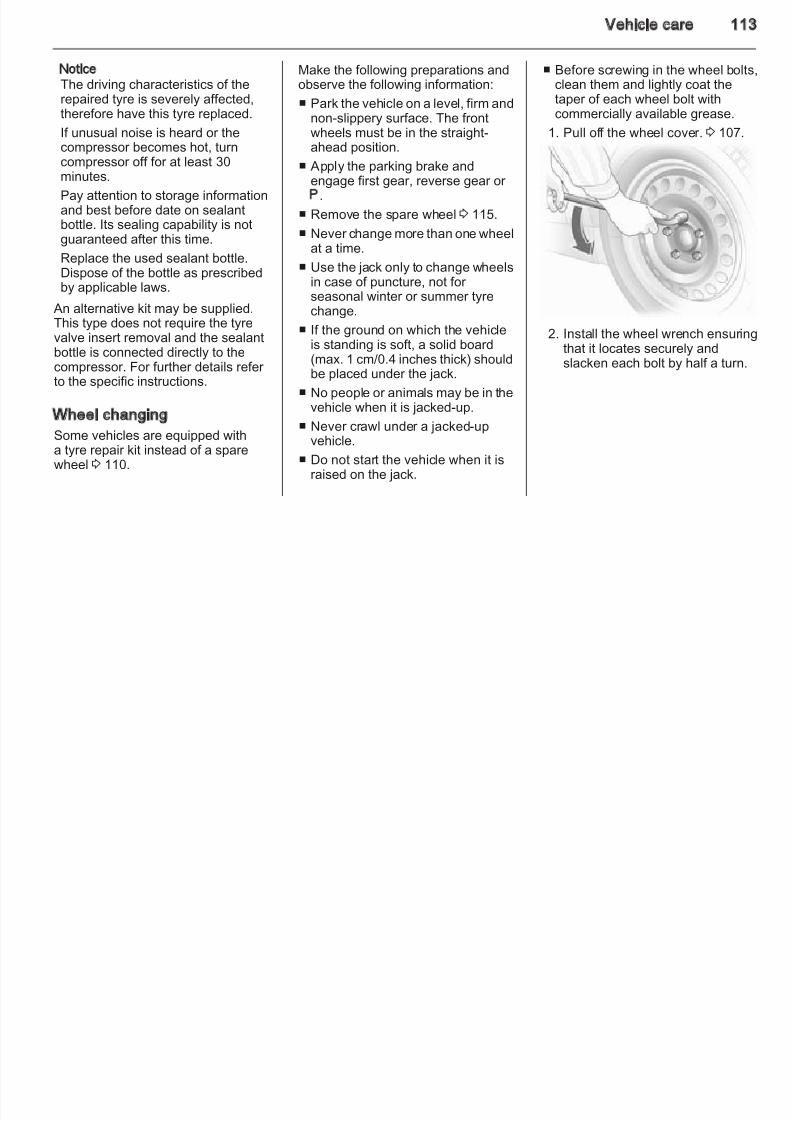
8/4/2019 Agila Owner's Manual - August 2009
http://slidepdf.com/reader/full/agila-owners-manual-august-2009 108/137
23 Manual transmission
24 Power windows
tyre repair kit 3 110, open tailgateand pull up load compartment floor carpet using the central strap locatednear the tailgate latch and hang thestring on the hook provided 3 46.
Vehicles with tyre repair kit
The tools and tyre repair kit are ina storage compartment below thefloor carpet in the load compartment.
The jack and the tools are ina stowage compartment in the load
compartment below the spare wheeSpare wheel 3 115.
108 Vehicle care
Wheels and tyres
Tyre condition, wheel conditionDrive over edges slowly and at rightangles if possible Driving over sharp
In accordance with country-specificregulations, affix the speed sticker inthe driver's field of view.
Tyre designations
Tyre pressure
Check the pressure of cold tyres atleast every 14 days and before anylong journey. Do not forget the sparewheel.
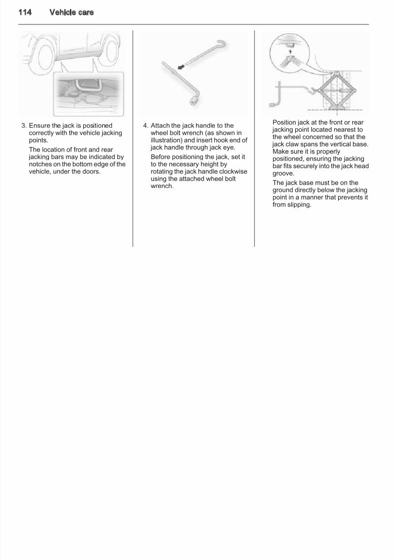
8/4/2019 Agila Owner's Manual - August 2009
http://slidepdf.com/reader/full/agila-owners-manual-august-2009 109/137
angles if possible. Driving over sharpedges can cause tyre and wheel
damage. Do not trap tyres on the kerbwhen parking.
Regularly check the wheels for damage. Seek the assistance of a workshop in the event of damage or unusual wear.
Tyres
Factory-fitted tyres are matched to
the chassis and offer optimum drivingcomfort and safety.
Winter tyres
Winter tyres improve driving safety attemperatures below 7 °C and shouldtherefore be fitted on all wheels.
Tyres of size 165/70 R 14
and 185/60 R 15 may be used aswinter tyres.
E.g. 185/65 R 15 88 T
185 = Tyre width, mm65 = Cross-section ratio (tyre
height to tyre width), %R = Belt type: RadialRF = Type: RunFlat15 = Wheel diameter, inches88 = Load index e.g. 88 is
equivalent to 567 kgT = Speed code letter
Speed code letter:Q = up to 100 mphS = up to 112 mphT = up to 118 mphH = up to 130 mphV = up to 150 mphW = up to 168 mph
Tyre pressure 3 130 and the label
located on the driver's door pillar.
The tyre pressure data refers to coldtyres. It applies to summer and winter tyres.
Always inflate the spare tyre to thepressure specified for full load.
The ECO tyre pressure serves toachieve the smallest amount of fuelconsumption possible.
Vehicle care 10
Incorrect tyre pressures will impair safety, vehicle handling, comfort andfuel economy and will increase tyrewear.
Changing tyre and wheel size
If tyres of a different size than thosefitted at the factory are used, it may bnecessary to reprogramme thespeedometer and make other vehicl
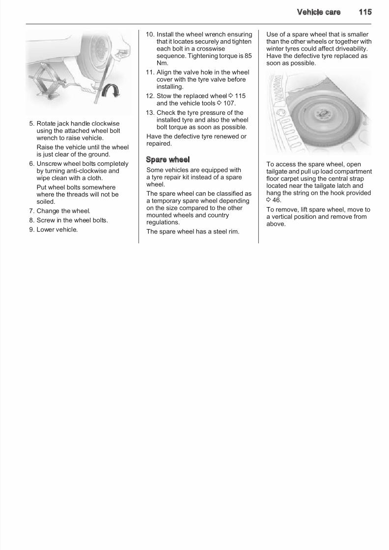
8/4/2019 Agila Owner's Manual - August 2009
http://slidepdf.com/reader/full/agila-owners-manual-august-2009 110/137
9 Warning
If the pressure is too low, this canresult in considerable tyre warm-up and internal damage, leading totread separation and even to tyreblow-out at high speeds.
Tread depth
Check tread depth at regular intervals.
Tyres should be replaced for safetyreasons at a tread depth of 2-3 mm (4mm for winter tyres).
The legally permissible minimumtread depth (1.6 mm) has beenreached when the tread has worndown as far as one of the tread wear
indicator s (TWI). Their position isindicated by markings on thesidewall.
If there is more wear at the front thanthe rear, swap round front wheels andrear wheels. Ensure that the directionof rotation of the wheels is the sameas before.
Tyres age, even if they are not used.
We recommend tyre replacementevery 6 years.
modifications.
9 Warning
Use of unsuitable tyres or wheelsmay lead to accidents and willinvalidate the vehicle typeapproval.
Wheel covers
Wheel covers and tyres that arefactory approved for the respectivevehicle and comply with all of therelevant wheel and tyre combinationrequirements must be used.
If the wheel covers and tyres used arnot factory approved, the tyres mustnot have a rim protection ridge
Wheel covers must not impair brake
cooling.
110 Vehicle care
9 Warning
Use of unsuitable tyres or wheelcovers could lead to suddenpressure loss and thereby
9 Warning
Damage may lead to tyre blowout.
The use of tyre chains is not permitted
Apply the parking brake and engagefirst gear, reverse gear or P.
8/4/2019 Agila Owner's Manual - August 2009
http://slidepdf.com/reader/full/agila-owners-manual-august-2009 111/137
accidents.
Tyre chains
Tyre chains are only permitted on thefront wheels.
Always use fine mesh chains that addno more than 10 mm to the tyre treadand the inboard sides (including chainlock).
y pon the temporary spare wheel.
Tyre repair kit
Minor damage to the tyre tread or sidewall can be repaired with the tyrerepair kit.
Do not remove foreign bodies fromthe tyres.
Tyre damage exceeding 4 mm or thatis at tyre's sidewall near the rim
cannot be repaired with the tyre repair kit.
9 Warning
Do not drive faster than 50 mph.
Do not use for a lengthy period.
Steering and handling may beaffected.
If your vehicle has a flat tyre:
The tyre repair kit is stowed beneaththe floor carpet in the loadcompartment.
Vehicle care 11
2. Unscrew valve cap from defectivetyre and unscrew valve insertusing supplied remover.
6. Screw tyre inflation hose to valve
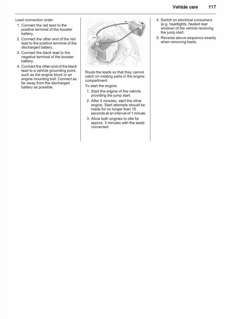
8/4/2019 Agila Owner's Manual - August 2009
http://slidepdf.com/reader/full/agila-owners-manual-august-2009 112/137
1. Shake sealant bottle, remove capand screw filler hose on to bottle,to pierce inner cap.
3. Remove the plug from the end of
the filler hose and insert filler hoseonto tyre valve.
4. Hold the sealant bottle withbottom pointing upwards andsqueeze all of the sealant into thetyre.
5. Disconnect filler hose and firmlyscrew insert into valve using thevalve insert remover.
If necessary, use the suppliedspare valve insert.
7. Place the compressor unit onlevel ground and unwrap the air compressor hose from the
compressor unit.Ensure the compressor on/off switch is in position O (off) andscrew the hose on to tyre valve.
8. Unwrap electrical connectioncable from the compressor unit.Insert plug into power outlet.
9. Turn ignition key to position ACC
To avoid discharging the batterywe recommend running theengine.
112 Vehicle care
tyre is too badly damaged. Seekthe assistance of a workshop.
If the tyre is overinflated, reducethe pressure by pressing thedeflation button on thecompressor
17. Continue driving immediately sothat sealant is evenly distributedthroughout the tyre. After drivingapprox. 3 miles (but no more than10 minutes), stop and check tyrepressure, using the compressor.
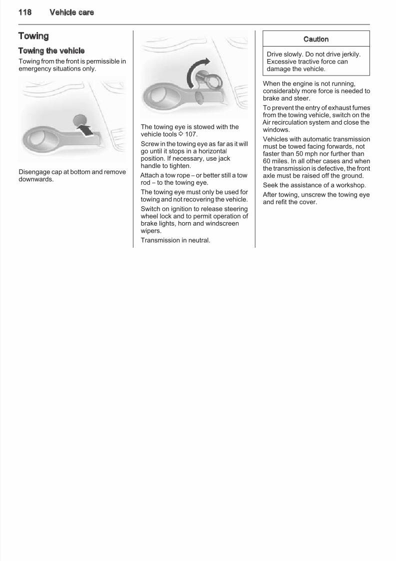
8/4/2019 Agila Owner's Manual - August 2009
http://slidepdf.com/reader/full/agila-owners-manual-august-2009 113/137
10. Switch compressor on/off switchto position I (on).
11. Inflate the tyre to the correctpressure 3 130. If there is no
reading, the air compressor hoseto tyre valve connection may befaulty. Re-check the connection.
If the prescribed tyre pressure isnot obtained within 10 minutes,remove the tyre repair kit. Movethe vehicle one tyre rotation.Reattach the tyre repair kit andcontinue the filling procedure for
10 minutes. If the prescribed tyrepressure is still not obtained, the
compressor.
Do not operate the compressor for
more than 10 minutes, to avoidoverheating.
12. When the correct tyre pressurehas been reached, switchcompressor on/off switch toposition O (off).
13. Remove plug fr om the power outlet, detach air compressor hose from tyre valve and replacevalve cap.
14. Return air compressor hose andelectrical connection cable to their original locations in thecompressor unit.
15. Remove any excess sealantusing a cloth.
16. Take the label indicating
maximum permitted speed fromthe kit and affix in the driver's fieldof view.
p , g p
18. If the tyre pressure has not
dropped below 1.3 bar, it may beadjusted to the prescribed value.Repeat the procedure until thereis no more loss of pressure.
19. Stow tyre repair kit below the floor carpet in the load compartment.
Vehicle care 11
NoticeThe driving characteristics of therepaired tyre is severely affected,therefore have this tyre replaced.
If unusual noise is heard or thecompressor becomes hot turn
Make the following preparations andobserve the following information:
■ Park the vehicle on a level, firm andnon-slippery surface. The frontwheels must be in the straight-ahead position
■ Before screwing in the wheel boltsclean them and lightly coat thetaper of each wheel bolt withcommercially available grease.
1. Pull off the wheel cover. 3 107.
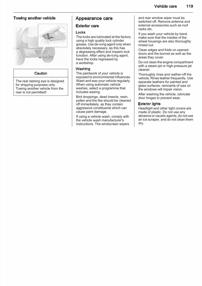
8/4/2019 Agila Owner's Manual - August 2009
http://slidepdf.com/reader/full/agila-owners-manual-august-2009 114/137
compressor becomes hot, turncompressor off for at least 30
minutes.Pay attention to storage informationand best before date on sealantbottle. Its sealing capability is notguaranteed after this time.
Replace the used sealant bottle.Dispose of the bottle as prescribedby applicable laws.
An alternative kit may be supplied.This type does not require the tyrevalve insert removal and the sealantbottle is connected directly to thecompressor. For further details refer to the specific instructions.
Wheel changing
Some vehicles are equipped with
a tyre repair kit instead of a sparewheel 3 110.
ahead position.
■ Apply the parking brake and
engage first gear, reverse gear or P.
■ Remove the spare wheel 3 115.
■ Never change more than one wheelat a time.
■ Use the jack only to change wheelsin case of puncture, not for seasonal winter or summer tyre
change.■ If the ground on which the vehicle
is standing is soft, a solid board(max. 1 cm/0.4 inches thick) shouldbe placed under the jack.
■ No people or animals may be in thevehicle when it is jacked-up.
■ Never crawl under a jacked-upvehicle.
■ Do not start the vehicle when it israised on the jack.
2. Install the wheel wrench ensurinthat it locates securely andslacken each bolt by half a turn.
114 Vehicle care
8/4/2019 Agila Owner's Manual - August 2009
http://slidepdf.com/reader/full/agila-owners-manual-august-2009 115/137
3. Ensure the jack is positionedcorrectly with the vehicle jackingpoints.
The location of front and rear
jacking bars may be indicated bynotches on the bottom edge of thevehicle, under the doors.
4. Attach the jack handle to thewheel bolt wrench (as shown inillustration) and insert hook end of jack handle through jack eye.
Before positioning the jack, set itto the necessary height byrotating the jack handle clockwiseusing the attached wheel boltwrench.
Position jack at the front or rear jacking point located nearest tothe wheel concerned so that the jack claw spans the vertical base.Make sure it is properly
positioned, ensuring the jackingbar fits securely into the jack headgroove.
The jack base must be on theground directly below the jackingpoint in a manner that prevents itfrom slipping.
Vehicle care 11
10. Install the wheel wrench ensuringthat it locates securely and tighteneach bolt in a crosswisesequence. Tightening torque is 85Nm.
11. Align the valve hole in the wheel
Use of a spare wheel that is smallerthan the other wheels or together witwinter tyres could affect driveability.Have the defective tyre replaced assoon as possible.
8/4/2019 Agila Owner's Manual - August 2009
http://slidepdf.com/reader/full/agila-owners-manual-august-2009 116/137
5. Rotate jack handle clockwiseusing the attached wheel boltwrench to raise vehicle.
Raise the vehicle until the wheel
is just clear of the ground.6. Unscrew wheel bolts completely
by turning anti-clockwise andwipe clean with a cloth.
Put wheel bolts somewherewhere the threads will not besoiled.
7. Change the wheel.
8. Screw in the wheel bolts.9. Lower vehicle.
11. Align the valve hole in the wheelcover with the tyre valve before
installing.12. Stow the replaced wheel 3 115
and the vehicle tools 3 107.
13. Check the tyre pressure of theinstalled tyre and also the wheelbolt torque as soon as possible.
Have the defective tyre renewed or repaired.
Spare wheel
Some vehicles are equipped witha tyre repair kit instead of a sparewheel.
The spare wheel can be classified asa temporary spare wheel dependingon the size compared to the other mounted wheels and country
regulations.The spare wheel has a steel rim.
To access the spare wheel, opentailgate and pull up load compartmenfloor carpet using the central straplocated near the tailgate latch andhang the string on the hook provided3 46.
To remove, lift spare wheel, move toa vertical position and remove from
above.
116 Vehicle care
Temporary spare wheelUse of the temporary spare wheelcould affect driveability. Have thedefective tyre renewed or repaired assoon as possible.
Only mount one temporary spare
Jump starting
Do not start with quick charger.
A vehicle with a discharged batterycan be started using jump leads andthe battery of another vehicle
■ Wear eye protection and protectiveclothing when handling a battery.
■ Use a booster battery with thesame voltage (12 volts). Its capacity(Ah) must not be much less thanthat of the discharged battery.
8/4/2019 Agila Owner's Manual - August 2009
http://slidepdf.com/reader/full/agila-owners-manual-august-2009 117/137
Only mount one temporary sparewheel. Do not drive faster than
50 mph. Take curves slowly. Do notuse for a long period of time.
Tyre chains 3 110.
Directional tyresFit directional tyres such that they rollin the direction of travel. The rollingdirection is indicated by a symbol(e.g. an arrow) on the sidewall.
The following applies to tyres fittedopposing the rolling direction:
■ Driveability may be affected. Havethe defective tyr e renewed or repaired as soon as possible.
■ Do not drive faster than 50 mph.
■ Drive particularly carefully on wetand snow-covered road surfaces.
the battery of another vehicle.
9 Warning
Be extremely careful when startingwith jump leads. Any deviationfrom the following instructions canlead to injuries or damage causedby battery explosion or damage tothe electrical systems of bothvehicles.
■ Never expose the battery to nakedflames or sparks.
■ A discharged battery can alreadyfreeze at a temperature of 0 °C.Defrost the frozen battery beforeconnecting jump leads.
■ Avoid contact with eyes, skin,fabrics and painted surfaces. The
fluid contains sulphuric acid whichcan cause injuries and damage inthe event of direct contact.
g y
■ Use jump leads with insulated
terminals and a cross section of atleast 16 mm2 (25 mm2 for dieselengines).
■ Do not disconnect the dischargedbattery from the vehicle.
■ Switch off all unnecessary electricalconsumers.
■ Do not lean over the battery during
jump starting.■ Do not allow the terminals of one
lead to touch those of the other lead.
■ The vehicles must not come intocontact with each other during the jump starting process.
■ Apply the parking brake,transmission in neutral, automatic
transmission in P.
Vehicle care 11
Lead connection order:
1. Connect the red lead to thepositive terminal of the booster battery.
2. Connect the other end of the redlead to the positive terminal of the
4. Switch on electrical consumers(e.g. headlights, heated rear window) of the vehicle receivingthe jump start.
5. Reverse above sequence exactlwhen removing leads.
8/4/2019 Agila Owner's Manual - August 2009
http://slidepdf.com/reader/full/agila-owners-manual-august-2009 118/137
lead to the positive terminal of thedischarged battery.
3. Connect the black lead to thenegative terminal of the booster battery.
4. Connect the other end of the blacklead to a vehicle grounding point,such as the engine block or anengine mounting bolt. Connect asfar away from the dischargedbattery as possible.
Route the leads so that they cannotcatch on rotating parts in the enginecompartment.
To start the engine:
1. Start the engine of the vehicleproviding the jump start.
2. After 5 minutes, start the other engine. Start attempts should bemade for no longer than 15seconds at an interval of 1 minute.
3. Allow both engines to idle for approx. 3 minutes with the leadsconnected.
g
118 Vehicle care
Towing
Towing the vehicle
Towing from the front is permissible inemergency situations only.
Caution
Drive slowly. Do not drive jerkily.Excessive tractive force candamage the vehicle.
8/4/2019 Agila Owner's Manual - August 2009
http://slidepdf.com/reader/full/agila-owners-manual-august-2009 119/137
Disengage cap at bottom and removedownwards.
The towing eye is stowed with thevehicle tools 3 107.
Screw in the towing eye as far as it willgo until it stops in a horizontal
position. If necessary, use jackhandle to tighten.
Attach a tow rope – or better still a towrod – to the towing eye.
The towing eye must only be used for towing and not recovering the vehicle.
Switch on ignition to release steeringwheel lock and to permit operation of brake lights, horn and windscreenwipers.
Transmission in neutral.
When the engine is not running,
considerably more force is needed tobrake and steer.
To prevent the entry of exhaust fumesfrom the towing vehicle, switch on the Air recirculation system and close thewindows.
Vehicles with automatic transmissionmust be towed facing forwards, notfaster than 50 mph nor further than60 miles. In all other cases and whenthe transmission is defective, the frontaxle must be raised off the ground.
Seek the assistance of a workshop.
After towing, unscrew the towing eyeand refit the cover.
Vehicle care 11
Towing another vehicle Appearance care
Exterior care
LocksThe locks are lubricated at the factoryusing a high quality lock cylinder
and rear window wiper must beswitched off. Remove antenna andexternal accessories such as roof racks etc.
If you wash your vehicle by hand,make sure that the insides of the
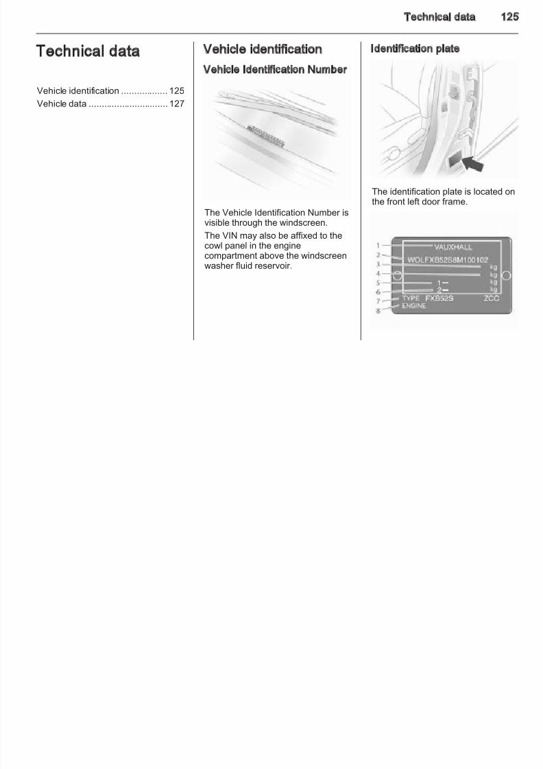
8/4/2019 Agila Owner's Manual - August 2009
http://slidepdf.com/reader/full/agila-owners-manual-august-2009 120/137
Caution
The rear lashing eye is designedfor shipping purposes only.Towing another vehicle from therear is not permitted!
using a high quality lock cylinder
grease. Use de-icing agent only whenabsolutely necessary, as this hasa degreasing effect and impairs lockfunction. After using de-icing agent,have the locks regreased bya workshop.
WashingThe paintwork of your vehicle isexposed to environmental influences.
Wash and wax your vehicle regularly.When using automatic vehiclewashes, select a programme thatincludes waxing.
Bird droppings, dead insects, resin,pollen and the like should be cleanedoff immediately, as they containaggressive constituents which cancause paint damage.
If using a vehicle wash, comply withthe vehicle wash manufacturer'sinstructions. The windscreen wipers
wheel housings are also thoroughly
rinsed out.Clean edges and folds on openeddoors and the bonnet as well as theareas they cover.
Do not clean the engine compartmenwith a steam-jet or high-pressure jetcleaner.
Thoroughly rinse and leather-of f thevehicle. Rinse leather frequently. Us
separate leathers for painted andglass surfaces: remnants of wax onthe windows will impair vision.
After washing the vehicle, lubricatedoor hinges to prevent wear.
Exterior lightsHeadlight and other light covers aremade of plastic. Do not use any
abrasive or caustic agents, do not usan ice scraper, and do not clean themdry.
120 Vehicle care
Polishing and waxingWax the vehicle regularly (at thelatest when water no longer beads).Otherwise, the paintwork will dry out.
Polishing is necessary only if the painthas become dull or if solid deposits
Clean smearing wiper blades witha soft cloth and window cleaner.
Wheels and tyresDo not use high-pressure jetcleaners.
Clean rims with a pH neutral wheel
Before and after winter, wash theunderbody and have the protectivewax coating checked.
Interior care
8/4/2019 Agila Owner's Manual - August 2009
http://slidepdf.com/reader/full/agila-owners-manual-august-2009 121/137
have become attached to it.
Paintwork polish with silicone formsa protective film, making waxingunnecessary.
Plastic body parts must not be treatedwith wax or polishing agents.
Windows and windscreen wiperbladesUse a soft lint-free cloth or chamois
leather together with window cleaner and insect remover.
When cleaning the rear window,make sure the heating element insidethe window is not damaged.
For mechanical removal of ice, usea sharp-edged ice scraper. Press thescraper firmly against the glass sothat no dirt can get under it and
scratch the glass.
Clean rims with a pH-neutral wheel
cleaner.Rims are painted and can be treatedwith the same agents as the body.
Paintwork damageRectify minor paintwork damage witha touch-up pen before rust forms.Have more extensive damage or rustareas repaired by a workshop.
UnderbodySome areas of the vehicle underbodyhave a PVC undercoating while other critical areas have a durableprotective wax coating.
After the underbody is washed, checkthe underbody and have it waxed if necessary.
Bitumen/rubber materials could
damage the PVC coating. Haveunderbody work carried out bya workshop.
Interior and upholstery
Only clean the vehicle interior,including the instrument panel fasciaand panelling, with a dry cloth or interior cleaner.
The instrument panel should only becleaned using a soft damp cloth.
Clean fabric upholstery witha vacuum cleaner and brush.Remove stains with an upholstery
cleaner.Clean seat belts with lukewarm water or interior cleaner.
Caution
Close Velcro fasteners as openVelcro fasteners on clothing coulddamage seat upholstery.
Vehicle care 12
Plastic and rubber partsPlastic and rubber parts can becleaned with the same cleaner asused to clean the body. Use interior cleaner if necessary. Do not use anyother agent. Avoid solvents and petrolin particular Do not use high
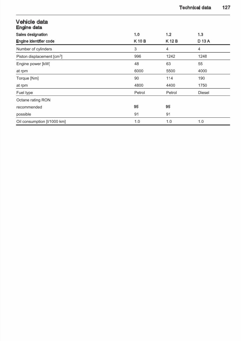
8/4/2019 Agila Owner's Manual - August 2009
http://slidepdf.com/reader/full/agila-owners-manual-august-2009 122/137
in particular. Do not use high-
pressure jet cleaners.
122 Service and maintenance
Service andmaintenance
General information ................... 122
General information
Service information
In order to ensure economical andsafe vehicle operation and tomaintain the value of your vehicle, it
Make sure that the Service andWarranty Booklet is completedcorrectly as continuous proof of service is essential if any warranty or goodwill claims are to be met, and isalso a benefit when selling thevehicle.
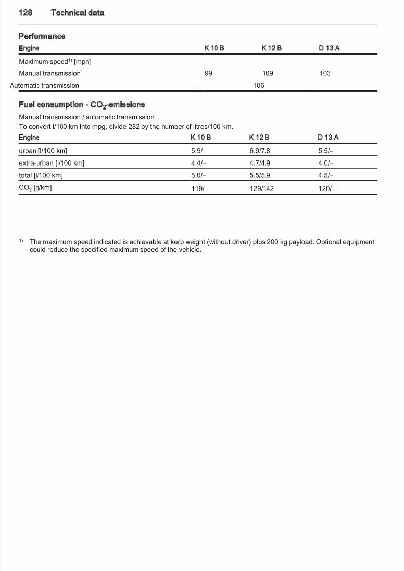
8/4/2019 Agila Owner's Manual - August 2009
http://slidepdf.com/reader/full/agila-owners-manual-august-2009 123/137
Recommended fluids, lubricantsand parts .................................... 123
is of vital importance that all
maintenance work is carried out at theproper intervals as specified.
The detailed, up-to-date serviceschedule for the vehicle is availablefrom your Vauxhall AuthorisedRepairer.
Service display 3 55.
Service interval
Maintenance of your vehicle isrequired every 10,000 miles or after 1 year, whichever occurs first, unlessotherwise indicated by the oil lifesystem.
ConfirmationsConfirmation of service is recorded inthe Service and Warranty Booklet.The date and mileage is completedwith the stamp and signature of theservicing workshop.
vehicle.
Fixed service intervalWhen service is due, InSP appears inthe odometer display when theignition is switched on. Have the nextservice performed by a workshopwithin one week or 300 miles(whichever occurs first).
Service and maintenance 12
Recommended fluids,lubricants and parts
Recommended fluids andlubricants
Only use products that have been
The new engine oil GM-Dexos 2 is of the highest quality available at themoment. If it is unavailable, engineoils of other listed qualities have to beused.
Engine oil quality
Use of ACEA A1/B1 and A5/B5engine oil is expressly forbidden,since they can cause long-termengine damage under certainoperating conditions.
Engine oil additives
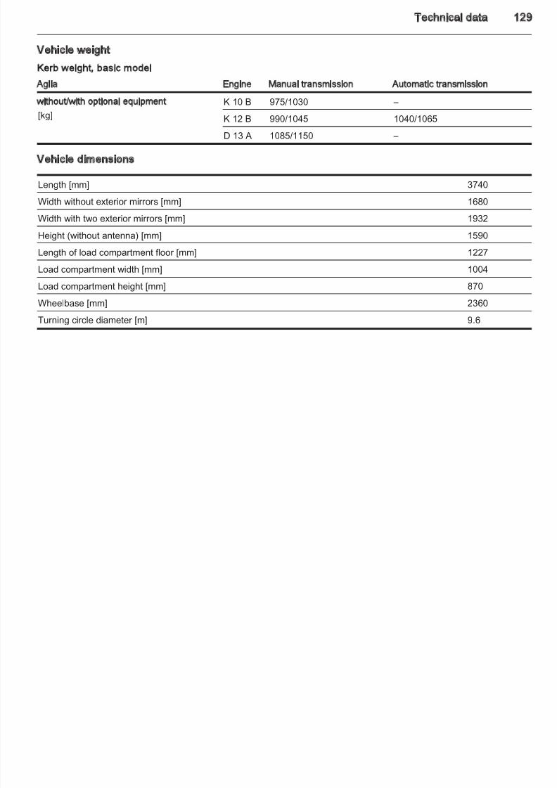
8/4/2019 Agila Owner's Manual - August 2009
http://slidepdf.com/reader/full/agila-owners-manual-august-2009 124/137
Only use products that have been
tested and approved. Damageresulting from the use of non-approved materials will not becovered by the warranty.
9 Warning
Operating materials arehazardous and could bepoisonous. Handle with care. Pay
attention to information given onthe containers.
Engine oilEngine oil is identified by its qualityand also its viscosity. Quality is moreimportant than viscosity whenselecting which engine oil to use.
GM-Dexos 2 = Petrol and diesel
enginesGM-LL-A-025 = Petrol enginesGM-LL-B-025 = Diesel engines ACEA-A3 = Petrol engines ACEA-B4 = Diesel engines
Topping up engine oil
Engine oils of different manufacturersand brands can be mixed as long asthey comply with the required engineoil (quality and viscosity).
If engine oil of the required quality isnot available, a maximum of 1 litre of ACEA A3/B4 or A3/B3 grade may beused (only once between each oilchange). The viscosity should be of the correct rating.
The use of engine oil additives could
cause damage and invalidate thewarranty.
Engine oil viscosity
Use only engine oil viscosities SAE0W-30, 0W-40, 5W-30 or 5W-40.
The SAE viscosity rating defines theability of an oil to flow. When cold, ois more viscous than when hot.
Multigrade oil is indicated by twofigures. The first figure, followed bya W, indicates low temperatureviscosity and the second figure thehigh temperature viscosity.
Coolant and antifreezeUse antifreeze of recommendedspecification.
124 Service and maintenance
The system is factory filled withcoolant designed for frost protectiondown to approx. -28 °C. Thisconcentration should be maintainedall year round.
Coolant additives intended to giveadditional corrosion protection or seal
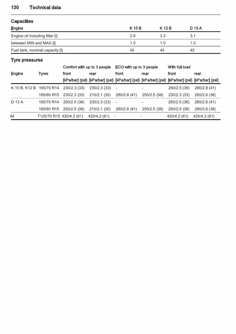
8/4/2019 Agila Owner's Manual - August 2009
http://slidepdf.com/reader/full/agila-owners-manual-august-2009 125/137
additional corrosion protection or seal
against minor leaks can causefunction problems. Liability for consequences resulting from the useof coolant additives will be rejected.
Brake and clutch fluidOnly use DOT4 brake fluid.
Over time, brake fluid absorbsmoisture which will reduce brakingeffectiveness. The brake fluid shouldtherefore be replaced at the specifiedinterval.
Brake fluid should be stored ina sealed container to avoid water absorption.
Ensure brake fluid does not becomecontaminated.
Technical data 12
Technical data
Vehicle identification .................. 125
Vehicle data ............................... 127
Vehicle identification
Vehicle Identification Number
Identification plate
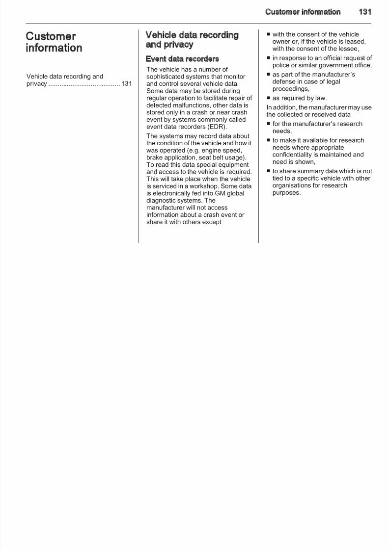
8/4/2019 Agila Owner's Manual - August 2009
http://slidepdf.com/reader/full/agila-owners-manual-august-2009 126/137
The Vehicle Identification Number isvisible through the windscreen.
The VIN may also be affixed to thecowl panel in the enginecompartment above the windscreenwasher fluid reservoir.
The identification plate is located onthe front left door frame.
126 Technical data
Information on identification plate:
1 = Manufacturer 2 = Vehicle Identification Number 3 = Permissible gross vehicle
weight rating4 = Permissible gross train weight
= Maximum permissible front axle
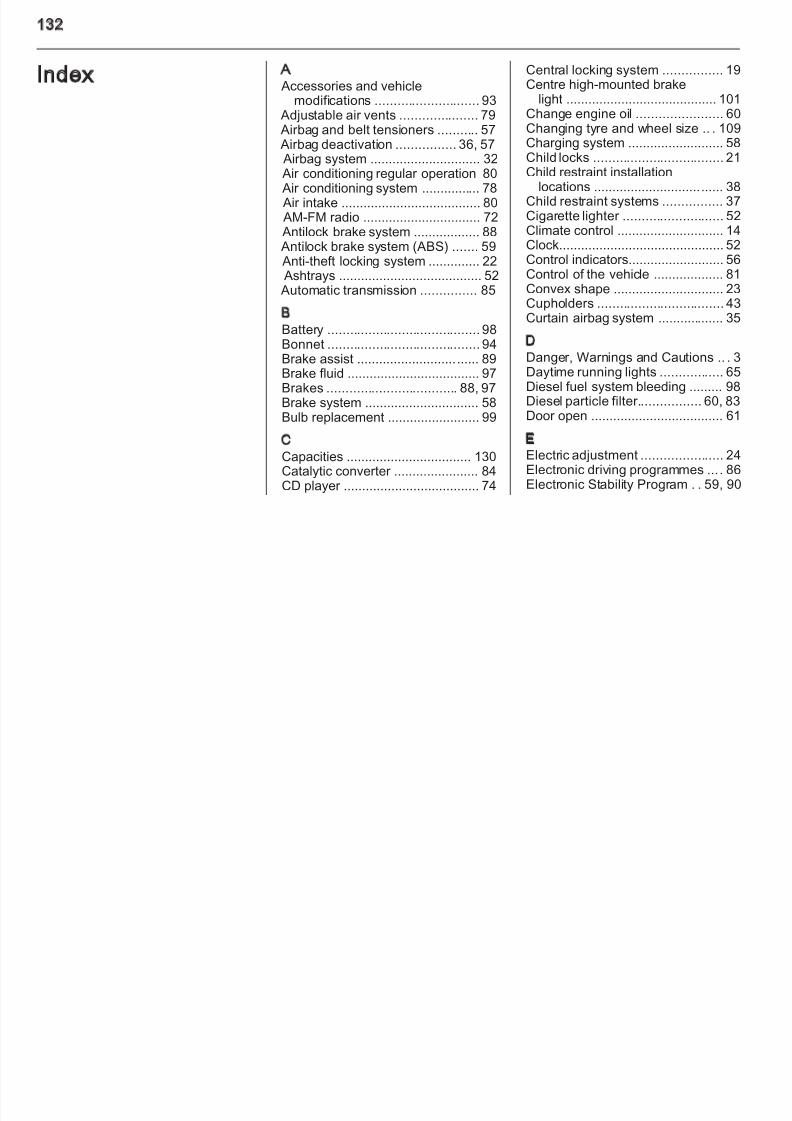
8/4/2019 Agila Owner's Manual - August 2009
http://slidepdf.com/reader/full/agila-owners-manual-august-2009 127/137
5 Maximum permissible front axle
load6 = Maximum permissible rear axleload
7 = Type approval number 8 = Engine designation
The combined total of front and rear axle loads must not exceed thepermissible gross vehicle weight. For example, if the front axle is bearing its
maximum permissible load, the rear axle can only bear a load that is equalto the gross vehicle weight minus thefront axle load.
The technical data is determined inaccordance with EuropeanCommunity standards. We reservethe right to make modifications.Specifications in the vehicle
documents always have priority over those given in this manual.
Technical data 12
Vehicle dataEngine data
Sales designation 1.0 1.2 1.3
Engine identifier code K 10 B K 12 B D 13 A
Number of cylinders 3 4 4
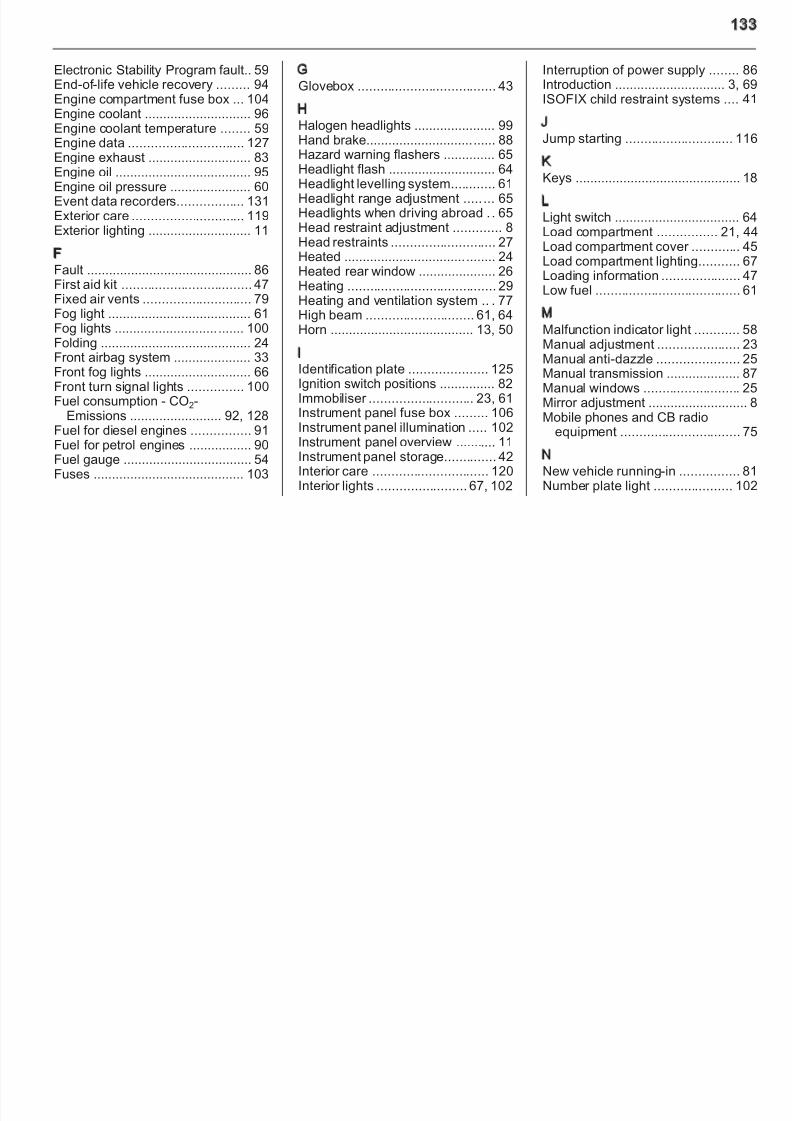
8/4/2019 Agila Owner's Manual - August 2009
http://slidepdf.com/reader/full/agila-owners-manual-august-2009 128/137
y
Piston displacement [cm3] 996 1242 1248
Engine power [kW] 48 63 55
at rpm 6000 5500 4000
Torque [Nm] 90 114 190
at rpm 4800 4400 1750
Fuel type Petrol Petrol Diesel
Octane rating RON
recommended 95 95
possible 91 91
Oil consumption [l/1000 km] 1.0 1.0 1.0
128 Technical data
Performance
Engine K 10 B K 12 B D 13 A
Maximum speed1) [mph]
Manual transmission 99 109 103
Automatic transmission – 106 –
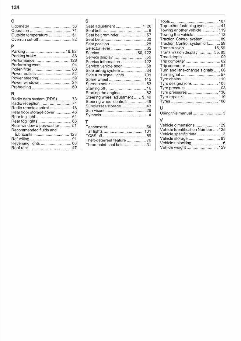
8/4/2019 Agila Owner's Manual - August 2009
http://slidepdf.com/reader/full/agila-owners-manual-august-2009 129/137
Automatic transmission – 106 –
Fuel consumption - CO2-emissions
Manual transmission / automatic transmission.
To convert l/100 km into mpg, divide 282 by the number of litres/100 km.
Engine K 10 B K 12 B D 13 A
urban [l/100 km] 5.9/– 6.9/7.8 5.5/–
extra-urban [l/100 km] 4.4/– 4.7/4.9 4.0/–
total [l/100 km] 5.0/– 5.5/5.9 4.5/–
CO2 [g/km] 119/– 129/142 120/–
1) The maximum speed indicated is achievable at kerb weight (without driver) plus 200 kg payload. Optional equipmentcould reduce the specified maximum speed of the vehicle.
Technical data 12
Vehicle weight
Kerb weight, basic model
Agila Engine Manual transmission Automatic transmission
without/with optional equipment
[kg]
K 10 B 975/1030 –
K 12 B 990/1045 1040/1065
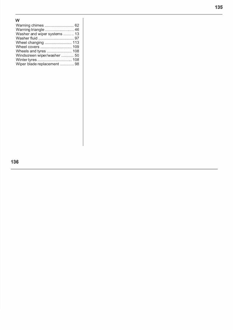
8/4/2019 Agila Owner's Manual - August 2009
http://slidepdf.com/reader/full/agila-owners-manual-august-2009 130/137
[ g] K 12 B 990/1045 1040/1065
D 13 A 1085/1150 –
Vehicle dimensions
Length [mm] 3740
Width without exterior mirrors [mm] 1680
Width with two exterior mirrors [mm] 1932
Height (without antenna) [mm] 1590
Length of load compartment floor [mm] 1227
Load compartment width [mm] 1004
Load compartment height [mm] 870
Wheelbase [mm] 2360
Turning circle diameter [m] 9.6
130 Technical data
Capacities
Engine K 10 B K 12 B D 13 A
Engine oil including filter [l] 2.9 3.3 3.1
between MIN and MAX [l] 1.0 1.0 1.0
Fuel tank nominal capacity [l] 45 45 45

8/4/2019 Agila Owner's Manual - August 2009
http://slidepdf.com/reader/full/agila-owners-manual-august-2009 131/137
Fuel tank, nominal capacity [l] 45 45 45
Tyre pressures
Comfort with up to 3 people ECO with up to 3 people With full load
Engine Tyres front rear front rear front rear
[kPa/bar] (psi) [kPa/bar] (psi) [kPa/bar] (psi) [kPa/bar] (psi) [kPa/bar] (psi) [kPa/bar] (psi)
K 10 B, K12 B 165/70 R14 230/2.3 (33) 230/2.3 (33) - - 250/2.5 (36) 280/2.8 (41)
185/60 R15 230/2.3 (33) 210/2.1 (30) 280/2.8 (41) 250/2.5 (36) 230/2.3 (33) 260/2.6 (38)
D 13 A 165/70 R14 250/2.5 (36) 230/2.3 (33) - - 250/2.5 (36) 280/2.8 (41)
185/60 R15 250/2.5 (36) 210/2.1 (30) 280/2.8 (41) 250/2.5 (36) 250/2.5 (36) 260/2.6 (38)
All T125/70 R15 420/4.2 (61) 420/4.2 (61) - - 420/4.2 (61) 420/4.2 (61)
Customer information 13
Customerinformation
Vehicle data recording andprivacy 131
Vehicle data recordingand privacy
Event data recorders
The vehicle has a number of sophisticated systems that monitor and control several vehicle data
■ with the consent of the vehicleowner or, if the vehicle is leased,with the consent of the lessee,
■ in response to an official request opolice or similar government office
■ as part of the manufacturer’sdefense in case of legal

8/4/2019 Agila Owner's Manual - August 2009
http://slidepdf.com/reader/full/agila-owners-manual-august-2009 132/137
privacy ....................................... 131 and control several vehicle data.
Some data may be stored duringregular operation to facilitate repair of detected malfunctions, other data isstored only in a crash or near crashevent by systems commonly calledevent data recorders (EDR).
The systems may record data aboutthe condition of the vehicle and how itwas operated (e.g. engine speed,
brake application, seat belt usage).To read this data special equipmentand access to the vehicle is required.This will take place when the vehicleis serviced in a workshop. Some datais electronically fed into GM globaldiagnostic systems. Themanufacturer will not accessinformation about a crash event or
share it with others except
g
proceedings,■ as required by law.
In addition, the manufacturer may usthe collected or received data
■ for the manufacturer's researchneeds,
■ to make it available for researchneeds where appropriate
confidentiality is maintained andneed is shown,
■ to share summary data which is notied to a specific vehicle with otheorganisations for researchpurposes.
132
Index A Accessories and vehicle
modifications ............................ 93 Adjustable air vents ..................... 79 Airbag and belt tensioners ........... 57 Airbag deactivation ................ 36, 57 Airbag system .............................. 32Air conditioning regular operation 80
Central locking system ................ 19Centre high-mounted brake
light ......................................... 101Change engine oil ....................... 60Changing tyre and wheel size .. . 109Charging system .......................... 58Child locks ................................... 21Child restraint installation

8/4/2019 Agila Owner's Manual - August 2009
http://slidepdf.com/reader/full/agila-owners-manual-august-2009 133/137
Air conditioning regular operation 80 Air conditioning system ................ 78 Air intake ...................................... 80 AM-FM radio ................................ 72 Antilock brake system .................. 88 Antilock brake system (ABS) ....... 59 Anti-theft locking system .............. 22 Ashtrays ....................................... 52 Automatic transmission ............... 85
BBattery ......................................... 98Bonnet ......................................... 94Brake assist ................................. 89Brake fluid .................................... 97Brakes ................................... 88, 97Brake system ............................... 58Bulb replacement ......................... 99
C
Capacities .................................. 130Catalytic converter ....................... 84CD player ..................................... 74
Child restraint installation
locations ................................... 38Child restraint systems ................ 37Cigarette lighter ........................... 52Climate control ............................. 14Clock............................................. 52Control indicators.......................... 56Control of the vehicle ................... 81Convex shape .............................. 23Cupholders .................................. 43
Curtain airbag system .................. 35DDanger, Warnings and Cautions .. . 3Daytime running lights ................. 65Diesel fuel system bleeding ......... 98Diesel particle filter................. 60, 83Door open .................................... 61
E
Electric adjustment ...................... 24Electronic driving programmes ... . 86Electronic Stability Program . . 59, 90
13
Electronic Stability Program fault.. 59End-of-life vehicle recovery ......... 94Engine compartment fuse box ... 104Engine coolant ............................. 96Engine coolant temperature ........ 59Engine data ............................... 127Engine exhaust ............................ 83Engine oil ..................................... 95
GGlovebox ..................................... 43
HHalogen headlights ...................... 99Hand brake................................... 88Hazard warning flashers .............. 65Headlight flash ............................. 64
Interruption of power supply ........ 8Introduction .............................. 3, 6ISOFIX child restraint systems .... 4
JJump starting ............................. 11
K

8/4/2019 Agila Owner's Manual - August 2009
http://slidepdf.com/reader/full/agila-owners-manual-august-2009 134/137
Engine oil ..................................... 95
Engine oil pressure ...................... 60Event data recorders.................. 131Exterior care .............................. 119Exterior lighting ............................ 11
FFault ............................................. 86First aid kit ................................... 47Fixed air vents ............................. 79Fog light ....................................... 61Fog lights ................................... 100Folding ......................................... 24Front airbag system ..................... 33Front fog lights ............................. 66Front turn signal lights ............... 100Fuel consumption - CO2-
Emissions ......................... 92, 128Fuel for diesel engines ................ 91Fuel for petrol engines ................. 90
Fuel gauge ................................... 54Fuses ......................................... 103
g
Headlight levelling system............ 61Headlight range adjustment ..... ... 65Headlights when driving abroad . . 65Head restraint adjustment ............. 8Head restraints ............................ 27Heated ......................................... 24Heated rear window ..................... 26Heating ........................................ 29Heating and ventilation system .. . 77
High beam ............................. 61, 64Horn ....................................... 13, 50
IIdentification plate ..................... 125Ignition switch positions ............... 82Immobiliser ............................ 23, 61Instrument panel fuse box ......... 106Instrument panel illumination ..... 102Instrument panel overview ........... 11
Instrument panel storage.............. 42Interior care ............................... 120Interior lights ........................ 67, 102
Keys ............................................. 1LLight switch .................................. 6Load compartment ................ 21, 4Load compartment cover ............. 4Load compartment lighting........... 6Loading information ..................... 4Low fuel ....................................... 6
MMalfunction indicator light ............ 5Manual adjustment ...................... 2Manual anti-dazzle ...................... 2Manual transmission .................... 8Manual windows .......................... 2Mirror adjustment ...........................Mobile phones and CB radio
equipment ................................ 7
NNew vehicle running-in ................ 8Number plate light ..................... 10
134
OOdometer ..................................... 53Operation ..................................... 71Outside temperature .................... 51Overrun cut-off ............................. 82
PParking .................................. 16, 82
SSeat adjustment ....................... 7, 28Seat belt ........................................ 8Seat belt reminder ....................... 57Seat belts ..................................... 30Seat position ................................ 28Selector lever ............................... 85Service ................................. 80, 122
Tools .......................................... 107Top-tether fastening eyes ............ 41Towing another vehicle .......... ... 119Towing the vehicle ..................... 118Traction Control system ............... 89Traction Control system off........... 59Transmission ......................... 15, 59Transmission display ............. 55, 85

8/4/2019 Agila Owner's Manual - August 2009
http://slidepdf.com/reader/full/agila-owners-manual-august-2009 135/137
Parking brake .............................. 88Performance .............................. 128Performing work .......................... 94Pollen filter ................................... 80Power outlets ............................... 52Power steering.............................. 59Power windows ............................ 25Preheating ................................... 60
R
Radio data system (RDS) ............ 73Radio reception ........................... 74Radio remote control ................... 18Rear floor storage cover .............. 46Rear fog light ............................... 61Rear fog lights ............................. 66Rear window wiper/washer .......... 51Recommended fluids and
lubricants ................................ 123
Refuelling ..................................... 91Reversing lights ........................... 66Roof rack ..................................... 47
Service ................................. 80, 122
Service display ............................ 55Service information .................... 122Service vehicle soon .................... 58Side airbag system ...................... 34Side turn signal lights ................ 101Spare wheel ............................... 115Speedometer ............................... 53Starting off ................................... 16Starting the engine ...................... 82
Steering wheel adjustment .... .. 9, 49Steering wheel controls ............... 49Sunglasses storage ..................... 43Sun visors .................................... 26Symbols ......................................... 4
TTachometer ................................. 54Tail lights ................................... 101TCSS off....................................... 59
Theft-deterrent feature ................. 70Three-point seat belt .................... 31
p y ,
Tread depth ............................... 109Trip computer .............................. 62Trip odometer .............................. 54Turn and lane-change signals .... . 66Turn signal ................................... 57Tyre chains ................................ 110Tyre designations ...................... 108Tyre pressure ............................ 108Tyre pressures ........................... 130
Tyre repair kit ............................. 110Tyres .......................................... 108
UUsing this manual .......................... 3
VVehicle dimensions .................... 129Vehicle Identification Number .... 125Vehicle specific data ...................... 3
Vehicle storage............................. 93Vehicle unlocking ........................... 6Vehicle weight ........................... 129
13
WWarning chimes ........................... 62Warning triangle .......................... 46Washer and wiper systems ....... .. 13Washer fluid ................................. 97Wheel changing ......................... 113Wheel covers ............................. 109Wheels and tyres ....................... 108

8/4/2019 Agila Owner's Manual - August 2009
http://slidepdf.com/reader/full/agila-owners-manual-august-2009 136/137
ee s a d y es 08
Windscreen wiper/washer ........... 50Winter tyres ............................... 108Wiper blade replacement ............. 98
136

8/4/2019 Agila Owner's Manual - August 2009
http://slidepdf.com/reader/full/agila-owners-manual-august-2009 137/137