Embed Size (px)
Citation preview

PUBLICATION SUPERSEDED This document was published by Austroads. Whilst it has been superseded by later publications, it has been made available electronically on the ARRB Knowledge Base for historical purposes with the permission of Austroads. For those seeking current material and guidance, please visit the Austroads online publications database: http://www.onlinepublications.austroads.com.au/
Austroads
Part 5: Structural Drafting
GUIDE TO BRIDGE TECHNOLOGY

Guide to Bridge TechnologyPart 5: Structural Drafting
Guide to Bridge Technology Part 5: Structural Drafting
SummaryPart 5 of the Guide to Bridge Technology – Structural Drafting sets out the principles involved in the presentation of bridge structural drawings and is intended to give engineers and draft persons at all levels a sound guide in drafting presentation and information.
The Guide covers a variety of principles used within bridge structural drafting practice including line work, text and dimensions, scales, definitions, drawing order and numbering, use of abbreviations and symbols, and concrete and reinforcement detailing.
KeywordsSketches, detailed design drawings, fabrication drawings, dimensions, symbols, patterns, setting out, cover sheet, general arrangement, footings, piles, concrete detailing, reinforcement detailing, structural steel detailing, vertical alignment, horizontal alignment.
First Published June 2009
© Austroads Inc. 2009
This work is copyright. Apart from any use as permitted under the Copyright Act 1968, no part may be reproduced by any process without the prior written permission of Austroads.
ISBN 978-1-921551-39-0
Austroads Project No. TP1564
Austroads Publication No. AGBT05/09
Project Manager Mark Bennett, RTA NSW
Prepared by Matthew Thompson
Published by Austroads Incorporated Level 9, Robell House 287 Elizabeth Street Sydney NSW 2000 Australia Phone: +61 2 9264 7088 Fax: +61 2 9264 1657 Email: [email protected]
This Guide is produced by Austroads as a general guide. Its application is discretionary. Road authorities may vary their practice according to local circumstances and policies.
Austroads believes this publication to be correct at the time of printing and does not accept responsibility for any consequences arising from the use of information herein. Readers should rely on their own skill and judgement to apply information to particular issues.

Guide to Bridge TechnologyPart 5: Structural Drafting
Sydney 2009

Austroads profile Austroads’ purpose is to contribute to improved Australian and New Zealand transport outcomes by:
providing expert advice to SCOT and ATC on road and road transport issues facilitating collaboration between road agencies promoting harmonisation, consistency and uniformity in road and related operations undertaking strategic research on behalf of road agencies and communicating outcomes promoting improved and consistent practice by road agencies.
Austroads membership Austroads membership comprises the six state and two territory road transport and traffic authorities, the Commonwealth Department of Infrastructure, Transport, Regional Development and Local Government in Australia, the Australian Local Government Association, and NZ Transport Agency. Austroads is governed by a council consisting of the chief executive officer (or an alternative senior executive officer) of each of its eleven member organisations:
Roads and Traffic Authority New South Wales Roads Corporation Victoria Department of Transport and Main Roads Queensland Main Roads Western Australia Department for Transport, Energy and Infrastructure South Australia Department of Infrastructure, Energy and Resources Tasmania Department of Planning and Infrastructure Northern Territory Department of Territory and Municipal Services Australian Capital Territory Department of Infrastructure, Transport, Regional Development and Local Government Australian Local Government Association New Zealand Transport Agency.
The success of Austroads is derived from the collaboration of member organisations and others in the road industry. It aims to be the Australasian leader in providing high quality information, advice and fostering research in the road sector.
GUIDE TO BRIDGE TECHNO LOGY PART 5 : STRUCTURAL DRAFT ING
A u s t r o a d s 2 0 0 9
— i —
CONTENTS
1 SCOPE AND GENERAL................................................................................................ 11.1 Scope.............................................................................................................................. 11.2 Application ...................................................................................................................... 11.3 Guide Structure............................................................................................................... 11.4 Definitions....................................................................................................................... 21.5 Types of Drawings ........................................................................................................ 10
1.5.1 Sketches ......................................................................................................... 101.5.2 Detailed Design Drawings .............................................................................. 101.5.3 Fabrication Drawings (Shop Drawing) ............................................................ 101.5.4 Works-as-Executed Drawings (As-Built Drawings or As-Constructed)........... 11
2 GENERAL APPLICATIONS ........................................................................................ 192.1 Line Work...................................................................................................................... 192.2 Text............................................................................................................................... 192.3 Dimensions ................................................................................................................... 19
2.3.1 Dimension Lines, Projection Lines and Leader Lines..................................... 192.4 Order of Dimensioning.................................................................................................. 202.5 Scales........................................................................................................................... 202.6 Drawing Order .............................................................................................................. 20
2.6.1 General ........................................................................................................... 202.6.2 Drawing Numbering ........................................................................................ 212.6.3 Title Blocks ..................................................................................................... 222.6.4 Titles and Sub-titles ........................................................................................ 22
2.7 Abbreviations ................................................................................................................ 232.7.1 Standard Abbreviations .................................................................................. 232.7.2 Acceptable Abbreviations ............................................................................... 232.7.3 Other Abbreviations ........................................................................................ 26
2.8 Symbols and Patterns................................................................................................... 262.8.1 Patterns .......................................................................................................... 262.8.2 Use of Symbols............................................................................................... 302.8.3 Welding........................................................................................................... 30
2.9 Notes and References.................................................................................................. 302.9.1 General Notes or Drawing Specific Notes ...................................................... 302.9.2 Particular Notes .............................................................................................. 31
2.10 Conventions.................................................................................................................. 312.10.1 Cross-referencing ........................................................................................... 312.10.2 Orientation of Views and Sections.................................................................. 32
2.11 Setting Out.................................................................................................................... 332.11.1 Chainage, Compass Bearing, Coordinates .................................................... 332.11.2 Survey Marks.................................................................................................. 342.11.3 Reduced Levels (Heights) .............................................................................. 34
3 PARTICULAR APPLICATIONS................................................................................... 353.1 Cover Sheet.................................................................................................................. 35
3.1.1 Information Shown.......................................................................................... 353.2 General Arrangement ................................................................................................... 40
3.2.1 General ........................................................................................................... 403.2.2 Plan View........................................................................................................ 403.2.3 Elevation ......................................................................................................... 41
GUIDE TO BRIDGE TECHNO LOGY PART 5 : STRUCTURAL DRAFT ING
A u s t r o a d s 2 0 0 9
— ii —
3.2.4 Typical Cross-section ..................................................................................... 423.2.5 Vertical and Horizontal Alignment Diagrams .................................................. 423.2.6 Skew Diagrams............................................................................................... 443.2.7 General Notes................................................................................................. 44
3.3 Footings and Piles ........................................................................................................ 503.3.1 General ........................................................................................................... 503.3.2 Piles ................................................................................................................ 503.3.3 Pile Setting Out............................................................................................... 513.3.4 Spread Footings/Footings............................................................................... 533.3.5 Footing Setting Out......................................................................................... 533.3.6 Rock Anchors ................................................................................................. 54
3.4 Concrete Detailing ........................................................................................................ 543.4.1 General ........................................................................................................... 543.4.2 Holes in Concrete, Cast-in Items .................................................................... 543.4.3 Dimensioning .................................................................................................. 553.4.4 Plan View........................................................................................................ 553.4.5 Elevation ......................................................................................................... 563.4.6 Section............................................................................................................ 573.4.7 Construction Joints ......................................................................................... 58
3.5 Concrete Reinforcement Detailing................................................................................ 593.5.1 General ........................................................................................................... 593.5.2 Detailing of Reinforcement ............................................................................. 593.5.3 Labelling Principles......................................................................................... 63
3.6 Structural Steel Detailing .............................................................................................. 703.6.1 General ........................................................................................................... 703.6.2 Standard Items ............................................................................................... 703.6.3 Non-standard Items ........................................................................................ 703.6.4 Closing Dimensions ........................................................................................ 703.6.5 Protective Treatment ...................................................................................... 71
REFERENCES ...................................................................................................................... 72
GUIDE TO BRIDGE TECHNO LOGY PART 5 : STRUCTURAL DRAFT ING
A u s t r o a d s 2 0 0 9
— iii —
TABLES
Table 1.1: Definitions provided for guidance ..................................................................... 3Table 2.1: Order of drawings ........................................................................................... 21Table 2.2: Metric abbreviations........................................................................................ 23Table 2.3: Acceptable abbreviations................................................................................ 24Table 2.4: Coordinates .................................................................................................... 34
FIGURES
Figure 1.1: Bridge components........................................................................................... 9Figure 1.2: RTA – Concept sketch.................................................................................... 12Figure 1.3: DTEI – Concept design – general arrangement ............................................. 13Figure 1.4: DTEI – Concept design – details .................................................................... 14Figure 1.5: QDMR – Preliminary general arrangement .................................................... 15Figure 1.6: RTA – Proposal sketch ................................................................................... 16Figure 1.7: VicRoads – Concept general arrangement – Part 1 ....................................... 17Figure 1.8: VicRoads – Concept general arrangement – Part 2 ....................................... 18Figure 2.1: Scale bars....................................................................................................... 20Figure 2.2: Sub-titles......................................................................................................... 23Figure 2.3: Hatching and patterns – 1............................................................................... 27Figure 2.4: Hatching and patterns – 2............................................................................... 28Figure 2.5: Hatching and patterns – 3............................................................................... 29Figure 2.6: Note leader convention................................................................................... 31Figure 2.7: Cross-referencing ........................................................................................... 31Figure 2.8: Compass bearing............................................................................................ 33Figure 3.1: DTEI – Cover sheet ........................................................................................ 36Figure 3.2: QDMR – Cover sheet ..................................................................................... 37Figure 3.3: RTA – Cover sheet ......................................................................................... 38Figure 3.4: VicRoads – Cover sheet ................................................................................. 39Figure 3.5: Vertical alignment diagram ............................................................................. 43Figure 3.6: Horizontal alignment diagram ......................................................................... 43Figure 3.7: Skew diagrams ............................................................................................... 44Figure 3.8: DTEI – General arrangement ......................................................................... 45Figure 3.9: RTA – General arrangement .......................................................................... 46Figure 3.10: VicRoads – General arrangement .................................................................. 47Figure 3.11: QDMR – General arrangement – Sheet 1 ...................................................... 48Figure 3.12: QDMR – General arrangement – Sheet 2 ...................................................... 49Figure 3.13: Pile layout – bearing and offsets..................................................................... 51Figure 3.14: Pile layout – pile coordinates .......................................................................... 52Figure 3.15: Piles in a group ............................................................................................... 52
GUIDE TO BRIDGE TECHNO LOGY PART 5 : STRUCTURAL DRAFT ING
A u s t r o a d s 2 0 0 9
— iv —
Figure 3.16: Footing layout ................................................................................................. 53Figure 3.17: Plan view ........................................................................................................ 56Figure 3.18: Elevation ......................................................................................................... 56Figure 3.19: Section 1......................................................................................................... 57Figure 3.20: Section 4......................................................................................................... 58Figure 3.21: Reinforcement label........................................................................................ 59Figure 3.22: Set of bars ...................................................................................................... 60Figure 3.23: Grade 250 label .............................................................................................. 60Figure 3.24: Plain round bar label....................................................................................... 60Figure 3.25: Labelling sequence – 1................................................................................... 61Figure 3.26: Labelling sequence – 2................................................................................... 62Figure 3.27: Non-standard label ......................................................................................... 63Figure 3.28: Elevation, plan and view – Detail principle ..................................................... 63Figure 3.29: Elevation, plan and view – Detail principle (variable bars).............................. 64Figure 3.30: Typical detailing for elevation, plan and view ................................................. 65Figure 3.31: Typical detailing for section – 1 ...................................................................... 66Figure 3.32: Typical detailing for section – 2 ...................................................................... 67Figure 3.33: Typical detailing for section – 3 ...................................................................... 67Figure 3.34: Incorrect detailing of a bar next to a view ....................................................... 68Figure 3.35: Typical lap detail ............................................................................................. 68Figure 3.36: Typical lap detail – useful for confined areas.................................................. 68Figure 3.37: Typical cranked lap detail ............................................................................... 69Figure 3.38: Reinforcing bars in a bundle ........................................................................... 69Figure 3.39: Typical detailing for bar bundles ..................................................................... 69
GUIDE TO BRIDGE TECHNO LOGY PART 5 : STRUCTURAL DRAFT ING
A u s t r o a d s 2 0 0 9
— 1 —
1 SCOPE AND GENERAL
1.1 ScopeThis Guide details the principles required in the presentation of bridge structural drawings.
The Guide is intended to cover the most common bridge information used, giving engineers and drafting persons at all levels of experience, a sound guide in drafting presentation and information.
For more detailed information, the relevant state road authority should be contacted to ascertain their requirements in the production of bridge structural drawings.
The Guide will cover a variety of areas within bridge structural drafting based on drafting principles such as the following:
line work, text and dimensions
scales
definitions
drawing order and numbering
use of abbreviations and symbols
concrete and reinforcement detailing.
1.2 ApplicationThe information contained in this Guide is intended for adoption by engineers and drafting persons throughout the industry. The Guide is intended for a common practice basis and to promote a consistency in application throughout the industry.
1.3 Guide Structure The Austroads Guide to Bridge Technology is published in seven Parts and addresses a range of bridge technology issues, each of which is summarised below.
Part 1: Introduction and Bridge Performance
This Part covers the scope of the Guide to Bridge Technology, includes factors affecting bridge performance, the relationship to the bridge design standards, and an understanding of the evolution of bridges and bridge loadings. Technical and non-technical design influences are also discussed along with the evolution of bridge construction methods and equipment. Specifications and quality assurance in bridge construction are also included in this Part.
Part 2: Materials
The full range of bridge building materials is discussed in Part 2 including concrete, steel, timber and non-metallic components. It also discusses the material characteristics including the individual stress mechanisms.
Part 3: Typical Superstructures, Substructures and Components
Included in discussion in this Part are superstructure and substructure components – namely timber, steel, wrought iron, reinforced and pre-stressed concrete. Typical bridge types such as suspension, cable stayed and arched types are discussed. Included in this Part is a section on bridge foundations.
GUIDE TO BRIDGE TECHNO LOGY PART 5 : STRUCTURAL DRAFT ING
A u s t r o a d s 2 0 0 9
— 2 —
Part 4: Design Procurement and Concept Design
In this Part, coverage includes bridge design process procurement models, specification requirements, design and delivery management processes, design checking and review concepts, the use of standardised components, aesthetics/architectural requirements, standard presentation of drawings and reports, designing for constructability and maintenance. The service life of the structure and components, mining and subsidence, flood plains, bridge loadings, and geotechnical and environmental considerations are also discussed.
Part 5: Structural Drafting
This Part covers the detailed drawing aspects required to clearly convey to the consultant/construction contractor the specifics of the project. It discusses the various standards including details required for cost estimating and material quantities. Coverage also includes reinforcement identification details.
Part 6: Bridge Construction
This Part provides guidance to the bridge owner's representative on site and focuses on bridge technology, high-risk construction processes e.g. piling, pre-stressing, and the relevant technical surveillance requirements during the construction phase. Bridge geometry, the management of existing road traffic and temporary works are also discussed in this Part.
Part 7: Maintenance and Management of Existing Bridges
Maintenance issues for timber, reinforced and pre-stressed concrete, steel, wrought and cast iron bridges are discussed in this Part. Other bridge components including bridge bearings and deck joints are also referred to. This Part also covers the monitoring, inspection and management of bridge conditions.
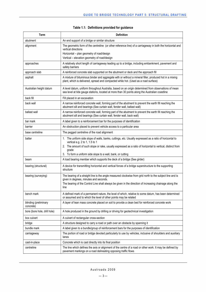
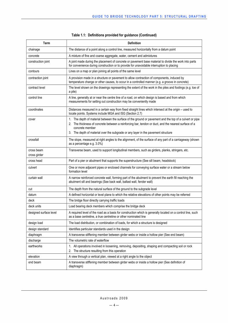
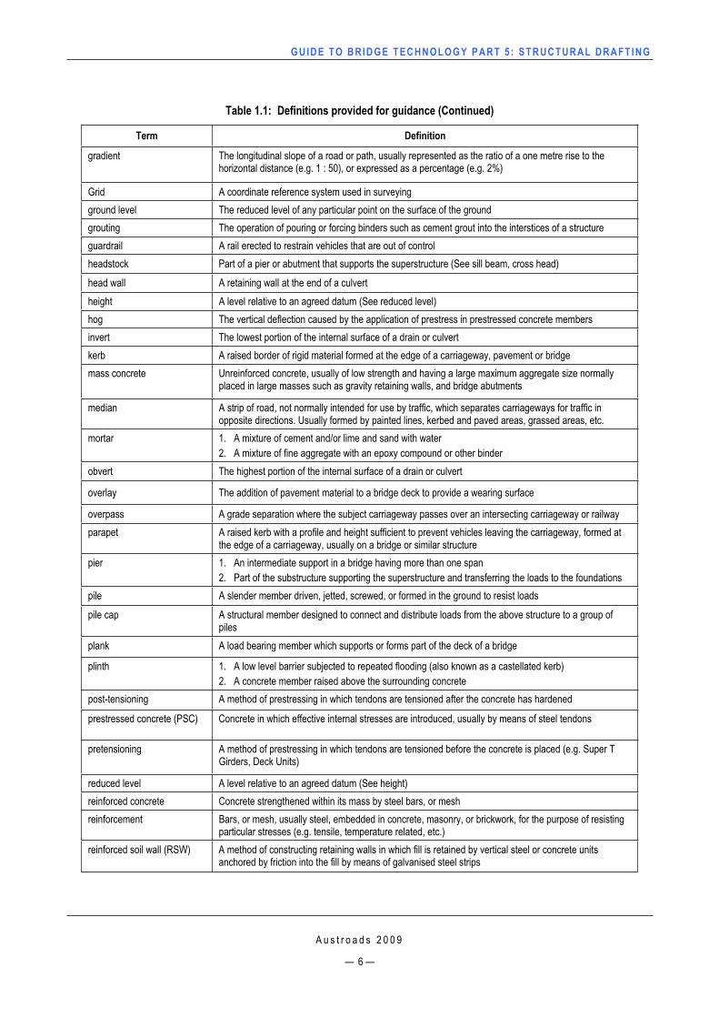
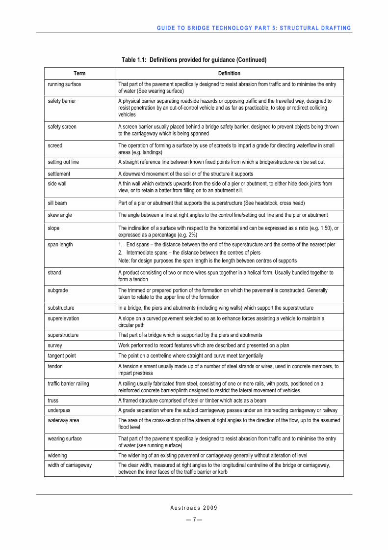
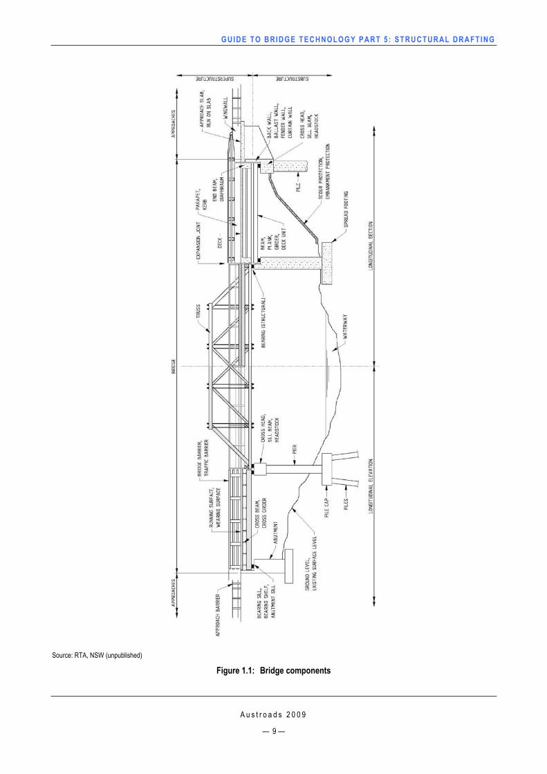
1.4 DefinitionsTable 1.1 lists a number of definitions provided for guidance and shall be used in preference to other terms. See Figure 1.1 for a diagrammatic view of a bridge structure showing bridge components and definitions.
GUIDE TO BRIDGE TECHNO LOGY PART 5 : STRUCTURAL DRAFT ING
A u s t r o a d s 2 0 0 9
— 3 —
Table 1.1: Definitions provided for guidance
Term Definition
abutment An end support of a bridge or similar structure alignment The geometric form of the centreline (or other reference line) of a carriageway in both the horizontal and
vertical directions Horizontal – plan geometry of road/design Vertical – elevation geometry of road/design
approaches A relatively short length of carriageway leading up to a bridge, including embankment, pavement and safety barriers
approach slab A reinforced concrete slab supported on the abutment or deck and the approach fill asphalt A mixture of bituminous binder and aggregate with or without a mineral filler, produced hot in a mixing
plant, which is delivered, spread and compacted while hot. (Used as a road surface)
Australian height datum A level datum, uniform throughout Australia, based on an origin determined from observations of mean sea level at tide gauge stations, located at more than 30 points along the Australian coastline
back fill Fill placed in an excavation back wall A narrow reinforced concrete wall, forming part of the abutment to prevent the earth fill reaching the
abutment sill and bearings (See curtain wall, fender wall, ballast wall) ballast wall A narrow reinforced concrete wall, forming part of the abutment to prevent the earth fill reaching the
abutment sill and bearings (See curtain wall, fender wall, back wall)
bar mark A label given to a reinforcement bar for the purposes of identification barrier An obstruction placed to prevent vehicle access to a particular area
base centreline The pegged centreline of the road alignment
batter 1. The uniform side slope of walls, banks, cuttings, etc. Usually expressed as a ratio of horizontal to vertical e.g. 2 to 1, 1.5 to 1
2. The amount of such slope or rake, usually expressed as a ratio of horizontal to vertical, distinct from grade
3. To form a uniform side slope to a wall, bank, or cutting beam A load bearing member which supports the deck of a bridge (See girder)
bearing (structural) A device for transmitting horizontal and vertical forces of a bridge superstructure to the supporting structure
bearing (surveying) The bearing of a straight line is the angle measured clockwise from grid north to the subject line and is given in degrees, minutes and seconds. The bearing of the Control Line shall always be given in the direction of increasing chainage along the line
bench mark A defined mark of a permanent nature, the level of which, relative to some datum, has been determined or assumed and to which the level of other points may be related
blinding (preliminary concrete)
A layer of lean mass concrete placed on soil to provide a clean bed for reinforced concrete work
bore (bore hole, drill hole) A hole produced in the ground by drilling or driving for geotechnical investigation
box culvert A culvert of rectangular cross-section bridge A structure designed to carry a road or path over an obstacle by spanning it bundle mark A label given to a bundle/group of reinforcement bars for the purposes of identification carriageway The portion of road or bridge devoted particularly to use by vehicles, inclusive of shoulders and auxiliary
lanes cast-in-place Concrete which is cast directly into its final position centreline The line which defines the axis or alignment of the centre of a road or other work. It may be defined by
pavement markings on a road delineating opposing traffic flows
GUIDE TO BRIDGE TECHNO LOGY PART 5 : STRUCTURAL DRAFT ING
A u s t r o a d s 2 0 0 9
— 4 —
Table 1.1: Definitions provided for guidance (Continued)
Term Definition
chainage The distance of a point along a control line, measured horizontally from a datum point
concrete A mixture of fine and coarse aggregate, water, cement and admixtures construction joint A joint made during the placement of concrete or pavement base material to divide the work into parts
for convenience during construction or to provide for unavoidable interruption to placing contours Lines on a map or plan joining all points of the same level
contraction joint A provision made in a structure or pavement to allow contraction of components, induced by temperature change or other causes, to occur in a controlled manner (e.g. a groove in concrete)
contract level The level shown on the drawings representing the extent of the work in the piles and footings (e.g. toe of a pile)
control line A line, generally at or near the centre line of a road, on which design is based and from which measurements for setting out construction may be conveniently made
coordinates Distances measured in a certain way from fixed straight lines which intersect at the origin – used to locate points. Systems include MGA and ISG (Section 2.7)
cover 1. The depth of material between the surface of the ground or pavement and the top of a culvert or pipe 2. The thickness of concrete between a reinforcing bar, tendon or duct, and the nearest surface of a
concrete member 3. The depth of material over the subgrade or any layer in the pavement structure
crossfall The slope, measured at right angles to the alignment, of the surface of any part of a carriageway (shown as a percentage e.g. 3.0%)
cross beam cross girder
Transverse beam, used to support longitudinal members, such as girders, planks, stringers, etc.
cross head Part of a pier or abutment that supports the superstructure (See sill beam, headstock)
culvert One or more adjacent pipes or enclosed channels for conveying surface water or a stream below formation level
curtain wall A narrow reinforced concrete wall, forming part of the abutment to prevent the earth fill reaching the abutment sill and bearings (See back wall, ballast wall, fender wall)
cut The depth from the natural surface of the ground to the subgrade level datum A defined horizontal or level plane to which the relative elevations of other points may be referred deck The bridge floor directly carrying traffic loads deck units Load bearing deck members which comprise the bridge deck
designed surface level A required level of the road as a basis for construction which is generally located on a control line, such as a base centreline, a true centreline or other nominated line
design load The load distribution, or combination of loads, for which a structure is designed
design standard Identifies particular standards used in the design diaphragm A transverse stiffening member between girder webs or inside a hollow pier (See end beam) discharge The volumetric rate of waterflow earthworks 1. All operations involved in loosening, removing, depositing, shaping and compacting soil or rock
2. The structure resulting from this operation elevation A view through a vertical plan, viewed at a right angle to the object end beam A transverse stiffening member between girder webs or inside a hollow pier (See definition of
diaphragm)
GUIDE TO BRIDGE TECHNO LOGY PART 5 : STRUCTURAL DRAFT ING
Table 1.1: Definitions provided for guidance (Continued)
Term Definition
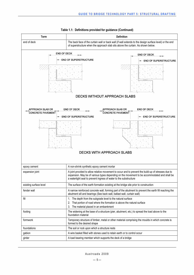
end of deck The back face of the curtain wall or back wall (if wall extends to the design surface level) or the end of superstructure when the approach slab sits above the curtain. As shown below.
epoxy cement A non-shrink synthetic epoxy cement mortar
expansion joint A joint provided to allow relative movement to occur and to prevent the build-up of stresses due to expansion. May be of various types depending on the movement to be accommodated and shall be a watertight seal to prevent ingress of water to the substructure
existing surface level The surface of the earth formation existing at the bridge site prior to construction
fender wall A narrow reinforced concrete wall, forming part of the abutment to prevent the earth fill reaching the abutment sill and bearings (See back wall, ballast wall, curtain wall)
fill 1. The depth from the subgrade level to the natural surface 2. That portion of road where the formation is above the natural surface 3. The material placed in an embankment
footing The widening at the base of a structure (pier, abutment, etc.) to spread the load above to the foundation material
formwork Temporary structure of timber, metal or other material comprising the moulds in which concrete is formed to the desired shape
foundations The soil or rock upon which a structure rests gabion A wire basket filled with stones used to retain earth or to control scour girder A load bearing member which supports the deck of a bridge
A u s t r o a d s 2 0 0 9
— 5 —
GUIDE TO BRIDGE TECHNO LOGY PART 5 : STRUCTURAL DRAFT ING
A u s t r o a d s 2 0 0 9
— 6 —
Table 1.1: Definitions provided for guidance (Continued)
Term Definition
gradient The longitudinal slope of a road or path, usually represented as the ratio of a one metre rise to the horizontal distance (e.g. 1 : 50), or expressed as a percentage (e.g. 2%)
Grid A coordinate reference system used in surveying ground level The reduced level of any particular point on the surface of the ground grouting The operation of pouring or forcing binders such as cement grout into the interstices of a structure guardrail A rail erected to restrain vehicles that are out of control headstock Part of a pier or abutment that supports the superstructure (See sill beam, cross head)
head wall A retaining wall at the end of a culvert height A level relative to an agreed datum (See reduced level) hog The vertical deflection caused by the application of prestress in prestressed concrete members invert The lowest portion of the internal surface of a drain or culvert kerb A raised border of rigid material formed at the edge of a carriageway, pavement or bridge mass concrete Unreinforced concrete, usually of low strength and having a large maximum aggregate size normally
placed in large masses such as gravity retaining walls, and bridge abutments
median A strip of road, not normally intended for use by traffic, which separates carriageways for traffic in opposite directions. Usually formed by painted lines, kerbed and paved areas, grassed areas, etc.
mortar 1. A mixture of cement and/or lime and sand with water 2. A mixture of fine aggregate with an epoxy compound or other binder
obvert The highest portion of the internal surface of a drain or culvert
overlay The addition of pavement material to a bridge deck to provide a wearing surface
overpass A grade separation where the subject carriageway passes over an intersecting carriageway or railway parapet A raised kerb with a profile and height sufficient to prevent vehicles leaving the carriageway, formed at
the edge of a carriageway, usually on a bridge or similar structure pier 1. An intermediate support in a bridge having more than one span
2. Part of the substructure supporting the superstructure and transferring the loads to the foundations pile A slender member driven, jetted, screwed, or formed in the ground to resist loads
pile cap A structural member designed to connect and distribute loads from the above structure to a group of piles
plank A load bearing member which supports or forms part of the deck of a bridge
plinth 1. A low level barrier subjected to repeated flooding (also known as a castellated kerb) 2. A concrete member raised above the surrounding concrete
post-tensioning A method of prestressing in which tendons are tensioned after the concrete has hardened
prestressed concrete (PSC) Concrete in which effective internal stresses are introduced, usually by means of steel tendons
pretensioning A method of prestressing in which tendons are tensioned before the concrete is placed (e.g. Super T Girders, Deck Units)
reduced level A level relative to an agreed datum (See height) reinforced concrete Concrete strengthened within its mass by steel bars, or mesh reinforcement Bars, or mesh, usually steel, embedded in concrete, masonry, or brickwork, for the purpose of resisting
particular stresses (e.g. tensile, temperature related, etc.) reinforced soil wall (RSW) A method of constructing retaining walls in which fill is retained by vertical steel or concrete units
anchored by friction into the fill by means of galvanised steel strips
GUIDE TO BRIDGE TECHNO LOGY PART 5 : STRUCTURAL DRAFT ING
A u s t r o a d s 2 0 0 9
— 7 —
Table 1.1: Definitions provided for guidance (Continued)
Term Definition
running surface That part of the pavement specifically designed to resist abrasion from traffic and to minimise the entry of water (See wearing surface)
safety barrier A physical barrier separating roadside hazards or opposing traffic and the travelled way, designed to resist penetration by an out-of-control vehicle and as far as practicable, to stop or redirect colliding vehicles
safety screen A screen barrier usually placed behind a bridge safety barrier, designed to prevent objects being thrown to the carriageway which is being spanned
screed The operation of forming a surface by use of screeds to impart a grade for directing waterflow in small areas (e.g. landings)
setting out line A straight reference line between known fixed points from which a bridge/structure can be set out
settlement A downward movement of the soil or of the structure it supports side wall A thin wall which extends upwards from the side of a pier or abutment, to either hide deck joints from
view, or to retain a batter from filling on to an abutment sill.
sill beam Part of a pier or abutment that supports the superstructure (See headstock, cross head)
skew angle The angle between a line at right angles to the control line/setting out line and the pier or abutment
slope The inclination of a surface with respect to the horizontal and can be expressed as a ratio (e.g. 1:50), or expressed as a percentage (e.g. 2%)
span length 1. End spans – the distance between the end of the superstructure and the centre of the nearest pier 2. Intermediate spans – the distance between the centres of piers Note: for design purposes the span length is the length between centres of supports
strand A product consisting of two or more wires spun together in a helical form. Usually bundled together to form a tendon
subgrade The trimmed or prepared portion of the formation on which the pavement is constructed. Generally taken to relate to the upper line of the formation
substructure In a bridge, the piers and abutments (including wing walls) which support the superstructure
superelevation A slope on a curved pavement selected so as to enhance forces assisting a vehicle to maintain a circular path
superstructure That part of a bridge which is supported by the piers and abutments
survey Work performed to record features which are described and presented on a plan
tangent point The point on a centreline where straight and curve meet tangentially
tendon A tension element usually made up of a number of steel strands or wires, used in concrete members, to impart prestress
traffic barrier railing A railing usually fabricated from steel, consisting of one or more rails, with posts, positioned on a reinforced concrete barrier/plinth designed to restrict the lateral movement of vehicles
truss A framed structure comprised of steel or timber which acts as a beam underpass A grade separation where the subject carriageway passes under an intersecting carriageway or railway waterway area The area of the cross-section of the stream at right angles to the direction of the flow, up to the assumed
flood level
wearing surface That part of the pavement specifically designed to resist abrasion from traffic and to minimise the entry of water (see running surface)
widening The widening of an existing pavement or carriageway generally without alteration of level width of carriageway The clear width, measured at right angles to the longitudinal centreline of the bridge or carriageway,
between the inner faces of the traffic barrier or kerb

GUIDE TO BRIDGE TECHNO LOGY PART 5 : STRUCTURAL DRAFT ING
A u s t r o a d s 2 0 0 9
— 8 —
Table 1.1: Definitions provided for guidance (Continued)
Term Definition
wing wall The extension of an abutment wall as in a bridge, or of an end wall in a culvert, used for retaining the side slopes of earth filling
works-as-executed plans (WAE)
A set of plans on which all variation to the original design, made during construction, are recorded for record purposes. Also referred to as ‘As built’ or ‘As constructed’ drawings
A comprehensive list of definitions can be found in: AS 1348 – Roads and Traffic Engineering – Glossary of Terms (2002) or Austroads – Glossary of Austroads Terms (2008).
GUIDE TO BRIDGE TECHNO LOGY PART 5 : STRUCTURAL DRAFT ING
Source: RTA, NSW (unpublished)
Figure 1.1: Bridge components
A u s t r o a d s 2 0 0 9
— 9 —
GUIDE TO BRIDGE TECHNO LOGY PART 5 : STRUCTURAL DRAFT ING
A u s t r o a d s 2 0 0 9
— 10 —
1.5 Types of Drawings All drawing types produced can be classified as follows:
1.5.1 SketchesSketches come in a number of forms depending on their intended use and requirements.
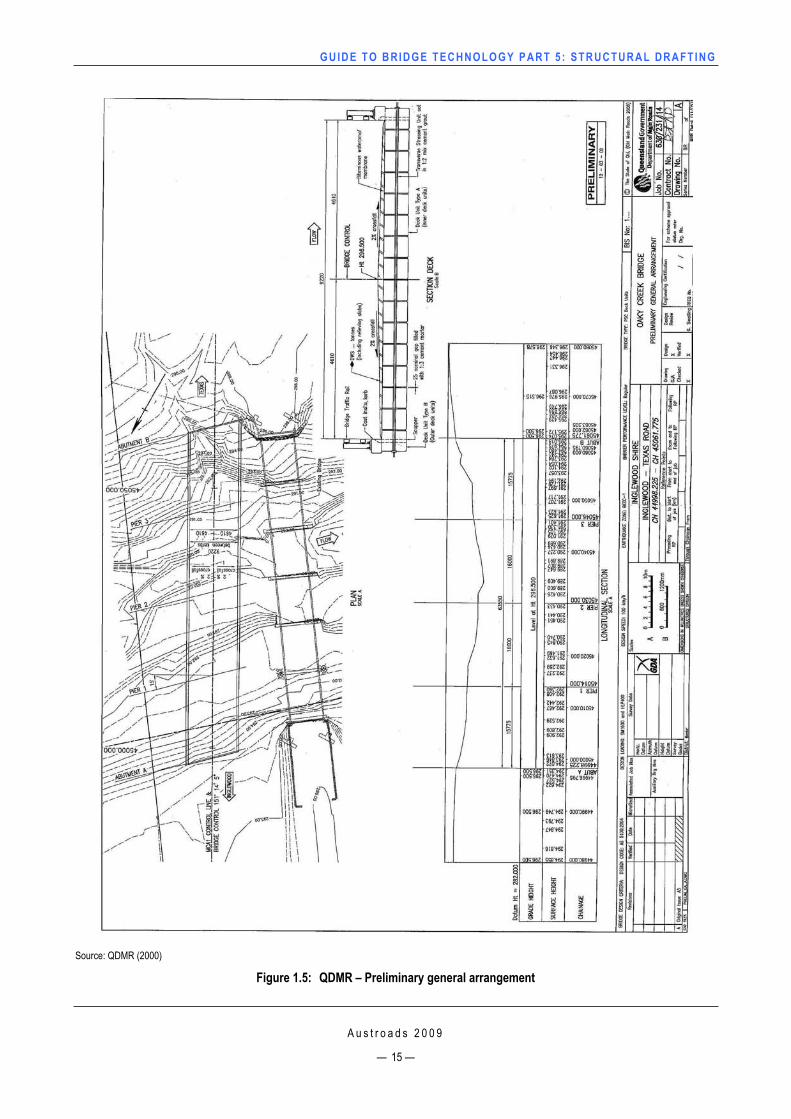
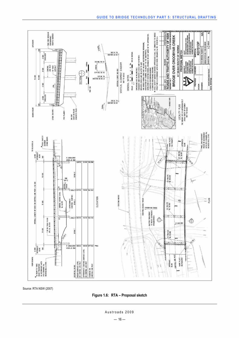
Proposal sketch – This is a plan or set of plans produced to depict what is considered to be the most appropriate design solution for the planned site. In some cases it may be deemed necessary to produce a number of alternative design options in order to help the designer receive client feedback prior to detailed design commencing. A proposal sketch shall contain the following information:
plan view
elevation
typical cross-section
locality plan (if applicable)
site plan (if applicable)
horizontal alignment diagram (if applicable)
vertical alignment diagram (if applicable)
general notes (if applicable).
A proposal sketch should show all necessary dimensions, notes and components, particular to the structure.
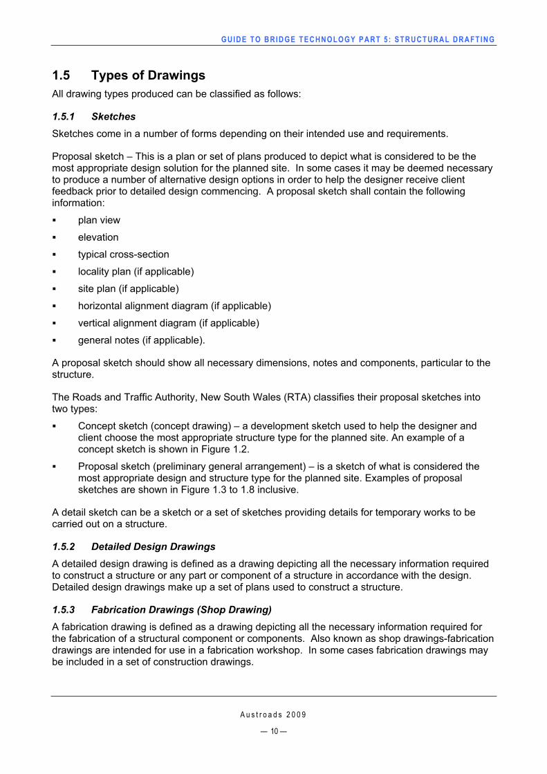
The Roads and Traffic Authority, New South Wales (RTA) classifies their proposal sketches into two types:
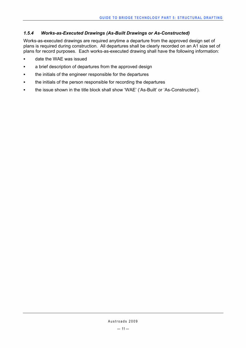
Concept sketch (concept drawing) – a development sketch used to help the designer and client choose the most appropriate structure type for the planned site. An example of a concept sketch is shown in Figure 1.2.
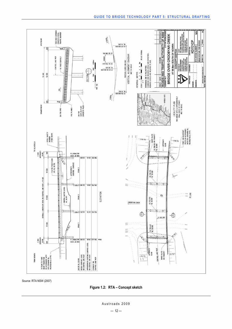
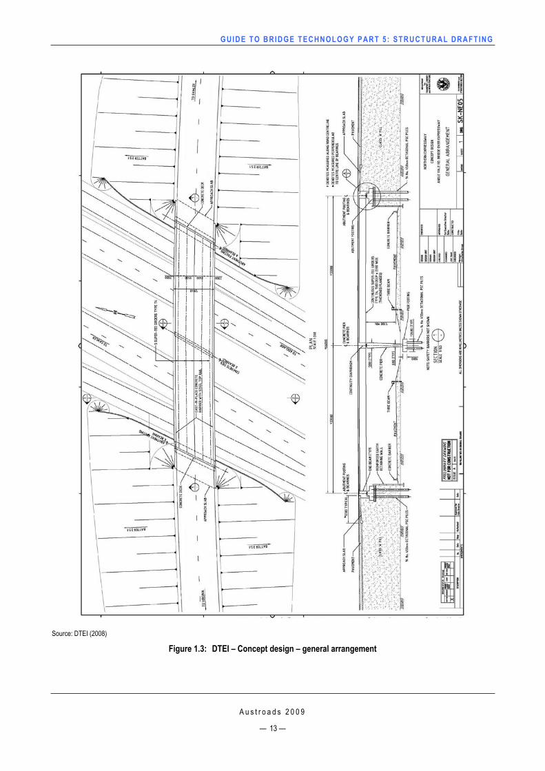
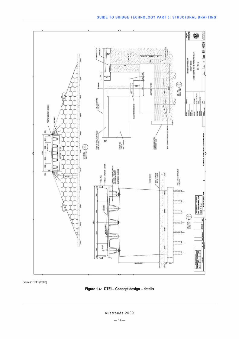
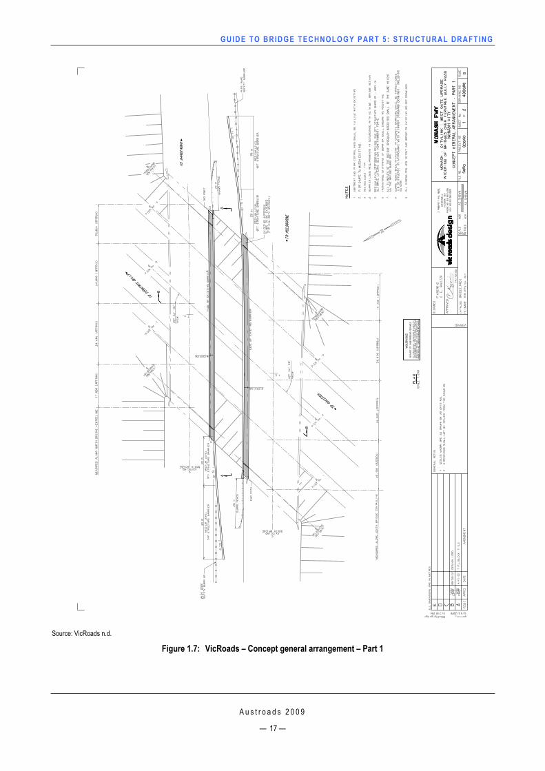
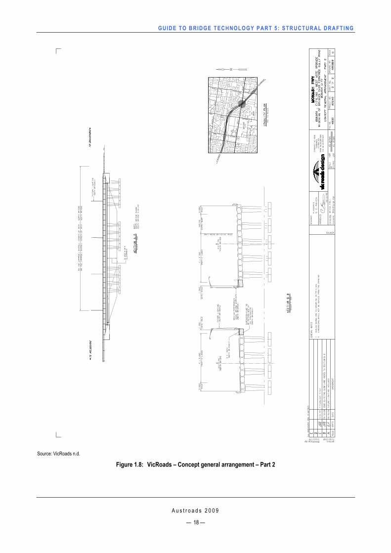
Proposal sketch (preliminary general arrangement) – is a sketch of what is considered the most appropriate design and structure type for the planned site. Examples of proposal sketches are shown in Figure 1.3 to 1.8 inclusive.
A detail sketch can be a sketch or a set of sketches providing details for temporary works to be carried out on a structure.
1.5.2 Detailed Design Drawings A detailed design drawing is defined as a drawing depicting all the necessary information required to construct a structure or any part or component of a structure in accordance with the design. Detailed design drawings make up a set of plans used to construct a structure.
1.5.3 Fabrication Drawings (Shop Drawing) A fabrication drawing is defined as a drawing depicting all the necessary information required for the fabrication of a structural component or components. Also known as shop drawings-fabrication drawings are intended for use in a fabrication workshop. In some cases fabrication drawings may be included in a set of construction drawings.
GUIDE TO BRIDGE TECHNO LOGY PART 5 : STRUCTURAL DRAFT ING
A u s t r o a d s 2 0 0 9
— 11 —
1.5.4 Works-as-Executed Drawings (As-Built Drawings or As-Constructed) Works-as-executed drawings are required anytime a departure from the approved design set of plans is required during construction. All departures shall be clearly recorded on an A1 size set of plans for record purposes. Each works-as-executed drawing shall have the following information:
date the WAE was issued
a brief description of departures from the approved design
the initials of the engineer responsible for the departures
the initials of the person responsible for recording the departures
the issue shown in the title block shall show ‘WAE’ (‘As-Built’ or ‘As-Constructed’).
GUIDE TO BRIDGE TECHNO LOGY PART 5 : STRUCTURAL DRAFT ING
Source: RTA NSW (2007)
Figure 1.2: RTA – Concept sketch
A u s t r o a d s 2 0 0 9
— 12 —
GUIDE TO BRIDGE TECHNO LOGY PART 5 : STRUCTURAL DRAFT ING
Source: DTEI (2008)
Figure 1.3: DTEI – Concept design – general arrangement
A u s t r o a d s 2 0 0 9
— 13 —
GUIDE TO BRIDGE TECHNO LOGY PART 5 : STRUCTURAL DRAFT ING
Source: DTEI (2008)
Figure 1.4: DTEI – Concept design – details
A u s t r o a d s 2 0 0 9
— 14 —
GUIDE TO BRIDGE TECHNO LOGY PART 5 : STRUCTURAL DRAFT ING
Source: QDMR (2000)
Figure 1.5: QDMR – Preliminary general arrangement
A u s t r o a d s 2 0 0 9
— 15 —
GUIDE TO BRIDGE TECHNO LOGY PART 5 : STRUCTURAL DRAFT ING
Source: RTA NSW (2007)
Figure 1.6: RTA – Proposal sketch
A u s t r o a d s 2 0 0 9
— 16 —
GUIDE TO BRIDGE TECHNO LOGY PART 5 : STRUCTURAL DRAFT ING
Source: VicRoads n.d.
Figure 1.7: VicRoads – Concept general arrangement – Part 1
A u s t r o a d s 2 0 0 9
— 17 —
GUIDE TO BRIDGE TECHNO LOGY PART 5 : STRUCTURAL DRAFT ING
Source: VicRoads n.d.
Figure 1.8: VicRoads – Concept general arrangement – Part 2
A u s t r o a d s 2 0 0 9
— 18 —
GUIDE TO BRIDGE TECHNO LOGY PART 5 : STRUCTURAL DRAFT ING
A u s t r o a d s 2 0 0 9
— 19 —
2 GENERAL APPLICATIONS
2.1 Line Work Line work on drawings should generally be in accordance with Table 3.1 in AS 1100 Part 101. Variations on the theme may be allowed according to the application.
2.2 TextThough full size drawings are produced for the final design, the minimum text size used should clearly be read on an A3 size set of plans, however font styles may vary and some examples of font styles used are listed below:
Department for Transport, Energy and Infrastructure, South Australia (DTEI) use the following text font:
— ISOCP (AutoCAD font) font style for all text
Department of Main Roads, Queensland (QDMR) uses the following text font:
— mr_romans (AutoCAD font) font style with a width factor of 0.8 for all text
The Roads and Traffic Authority, New South Wales (RTA) uses the following text fonts:
— International ISO (Microstation font) font style for general use and dimensions — Arial font style for text in the title blocks
Roads Corporation, Victoria (VicRoads) use the following text font:
— StenceQ font from a Microstation resource file
Main Roads Western Australia (MRWA) use the following text font:
— ISOCP2 (Autocad font) front style with a width factor of 1.0 for all text.
2.3 Dimensions Each dimension necessary for the complete definition of a particular element shall be clearly shown on the drawing and shall be shown only once. The dimensioning of any element shall not be such, that a dimension relating to that element shall need to be deduced from other dimensions, nor, that the drawing must be scaled to determine a dimension.
In all cases, dimensions shown on drawings shall be in millimetres and they shall be shown in accordance with AS 1100 Part 101.
A chain of dimensions shall be covered by an overall dimension except where dimensional tolerances are of critical importance.
Where practical, dimensions shall be placed using the aligned method with each dimension placed parallel to its dimension line in order to be read from either the bottom or the right hand side of the drawing.
2.3.1 Dimension Lines, Projection Lines and Leader Lines Dimension lines shall not be interrupted for the insertion of dimensions and shall terminate in easily readable arrowheads or a small circle as appropriate.
Dimension lines shall not be shown as centrelines or as part of an element’s outline.
GUIDE TO BRIDGE TECHNO LOGY PART 5 : STRUCTURAL DRAFT ING
Projection lines for dimensions shall extend from a point no less than 2 mm (A1 drawing) from the surface of the object to a point not less than 2 mm beyond the dimension line. Projection lines shall, in the majority of cases, be unbroken.
Leader lines for notes shall commence from either the beginning or the end of a note with a short (minimum length 3 mm) horizontal line before being angled to the point of reference. The termination of the leader line shall be with an arrow to the outline of the element or a small fully shaded circle (nominal 3.5 mm diameter – A1 drawing) within the area being noted.
2.4 Order of Dimensioning All components shall be drawn to an accuracy of 1 mm.
The following order of accuracy shall be used on all drawings:
Concrete dimensions 1 mm
Reinforcing bar spacing 5 mm
Steel plate widths 1 mm
Steel plate lengths 1 mm (as necessary for cambered plates etc.)
Steel sections 0.1 mm (or as shown in manufacturers’ catalogues, etc.).
2.5 ScalesScale used on drawings will vary in accordance with the size and character of the feature being detailed or the degree of detailing required.
The scales on all drawings should be drawn to a defined natural scale (A1 drawing) with the scale to be such, as to be easily read on an A3 size drawing.
Distorted scales should only be used under special circumstances where clarity is the most important feature.
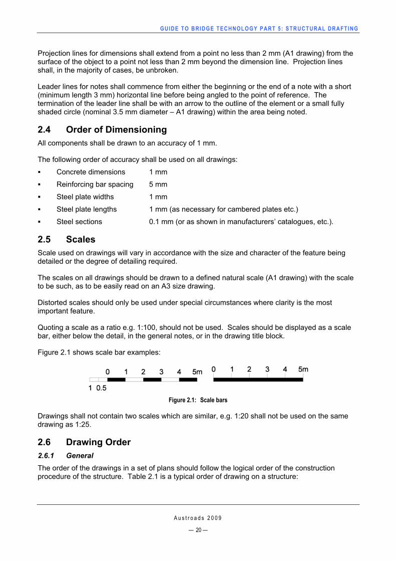
Quoting a scale as a ratio e.g. 1:100, should not be used. Scales should be displayed as a scale bar, either below the detail, in the general notes, or in the drawing title block.
Figure 2.1 shows scale bar examples:
Figure 2.1: Scale bars
Drawings shall not contain two scales which are similar, e.g. 1:20 shall not be used on the same drawing as 1:25.
2.6 Drawing Order 2.6.1 GeneralThe order of the drawings in a set of plans should follow the logical order of the construction procedure of the structure. Table 2.1 is a typical order of drawing on a structure:
A u s t r o a d s 2 0 0 9
— 20 —
GUIDE TO BRIDGE TECHNO LOGY PART 5 : STRUCTURAL DRAFT ING
A u s t r o a d s 2 0 0 9
— 21 —
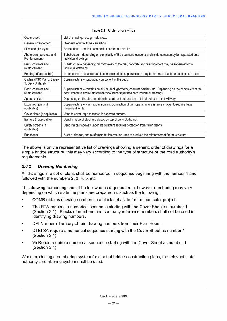
Table 2.1: Order of drawings
Cover sheet List of drawings, design notes, etc. General arrangement Overview of work to be carried out. Piles and pile layout Foundations - the first construction carried out on site. Abutments (concrete and Reinforcement)
Substructure - depending on complexity of the abutment, concrete and reinforcement may be separated onto individual drawings.
Piers (concrete and reinforcement)
Substructure – depending on complexity of the pier, concrete and reinforcement may be separated onto individual drawings.
Bearings (if applicable) In some cases expansion and contraction of the superstructure may be so small, that bearing strips are used. Girders (PSC Plank, Super-T, Deck Units, etc.)
Superstructure – supporting component of the deck.
Deck (concrete and reinforcement)
Superstructure – contains details on deck geometry, concrete barriers etc. Depending on the complexity of the deck, concrete and reinforcement should be separated onto individual drawings.
Approach slab Depending on the placement on the abutment the location of this drawing in a set will vary. Expansion joints (if applicable)
Superstructure – when expansion and contraction of the superstructure is large enough to require large movement joints.
Cover plates (if applicable Used to cover large recesses in concrete barriers. Barriers (if applicable) Usually made of steel and placed on top of concrete barrier. Safety screens (if applicable)
Used if a carriageway under the structure requires protection from fallen debris.
Bar shapes A set of shapes, and reinforcement information used to produce the reinforcement for the structure.
The above is only a representative list of drawings showing a generic order of drawings for a simple bridge structure, this may vary according to the type of structure or the road authority’s requirements.
2.6.2 Drawing Numbering All drawings in a set of plans shall be numbered in sequence beginning with the number 1 and followed with the numbers 2, 3, 4, 5, etc.
This drawing numbering should be followed as a general rule; however numbering may vary depending on which state the plans are prepared in, such as the following:
QDMR obtains drawing numbers in a block set aside for the particular project.
The RTA requires a numerical sequence starting with the Cover Sheet as number 1 (Section 3.1). Blocks of numbers and company reference numbers shall not be used in identifying drawing numbers.
DPI Northern Territory obtain drawing numbers from their Plan Room.
DTEI SA require a numerical sequence starting with the Cover Sheet as number 1 (Section 3.1).
VicRoads require a numerical sequence starting with the Cover Sheet as number 1 (Section 3.1).
When producing a numbering system for a set of bridge construction plans, the relevant state authority’s numbering system shall be used.
GUIDE TO BRIDGE TECHNO LOGY PART 5 : STRUCTURAL DRAFT ING
A u s t r o a d s 2 0 0 9
— 22 —
2.6.3 Title Blocks All drawing sheets shall carry a title block and shall adhere to the requirements of each road authority.
Cover Sheets may or may not require title blocks. This will depend on the road authority.
2.6.4 Titles and Sub-titles Titles
The title block on every sheet of a set of drawings shall have the same identifying title which adequately describes the location of the structure site.
The Roads and Traffic Authority also requires the road number and the Local Government Area name.
The title block of each sheet shall also include a description of the details shown on that sheet, e.g. piers concrete, piers reinforcement, piers profile.
Where more than one sheet is required to detail a part of a structure, it shall be considered to be a sheet series and the sheet titles shall reflect the particular situation. Examples of sheet series titles are:
DTEI SA uses the following labelling system:
— DECK 1 — DECK 2 — DECK 3
The RTA uses the following labelling system:
— DECK CONCRETE – SHEET A — DECK CONCRETE – SHEET B — DECK CONCRETE – SHEET C
QDMR uses the following labelling system:
— DECK – SHEET 1 — DECK – SHEET 2 — DECK – SHEET 3
VicRoads uses the following labelling system:
— OVERLAY – PART 1 — OVERLAY – PART 2 — OVERLAY – PART 3.
Sub-titles
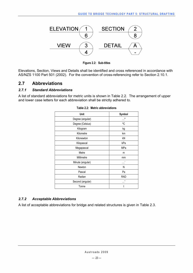
A sheet generally comprises several views, sections, details, tables, etc., and each shall be given an appropriate sub-title, e.g. plan, elevation. (Figure 2.2)
GUIDE TO BRIDGE TECHNO LOGY PART 5 : STRUCTURAL DRAFT ING
Figure 2.2: Sub-titles
Elevations, Section, Views and Details shall be identified and cross referenced in accordance with AS/NZS 1100 Part 501 (2002). For the convention of cross-referencing refer to Section 2.10.1.
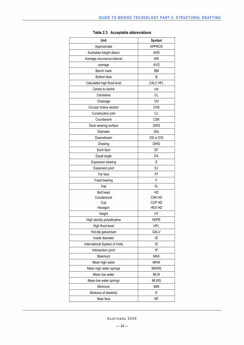
2.7 Abbreviations2.7.1 Standard Abbreviations A list of standard abbreviations for metric units is shown in Table 2.2. The arrangement of upper and lower case letters for each abbreviation shall be strictly adhered to.
Table 2.2: Metric abbreviations
Unit SymbolDegree (angular) …ºDegree (Celsius) ºC
Kilogram kg Kilometre km
Kilonewton kNKilopascal kPa
Megapascal MPaMetre m
Millimetre mmMinute (angular) …’
Newton NPascal PaRadian RAD
Second (angular) …” Tonne t
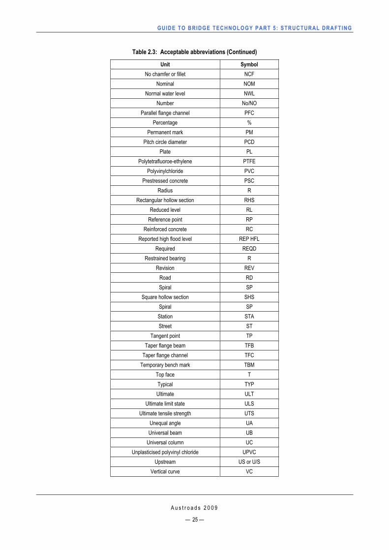
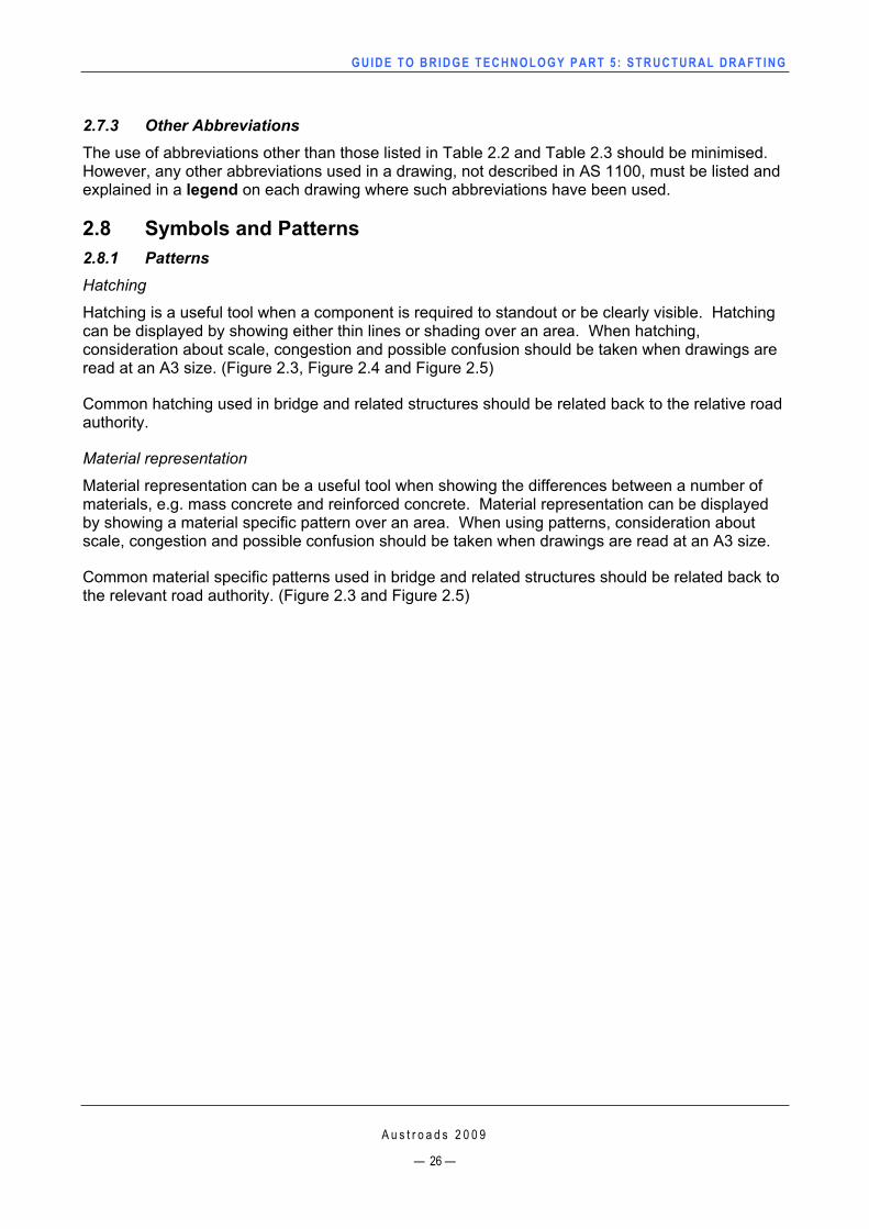
2.7.2 Acceptable Abbreviations A list of acceptable abbreviations for bridge and related structures is given in Table 2.3.
A u s t r o a d s 2 0 0 9
— 23 —
GUIDE TO BRIDGE TECHNO LOGY PART 5 : STRUCTURAL DRAFT ING
A u s t r o a d s 2 0 0 9
— 24 —
Table 2.3: Acceptable abbreviations
Unit SymbolApproximate APPROX
Australian height datum AHDAverage recurrence interval ARI
average AVGBench mark BMBottom face B
Calculated high flood level CALC HFL Centre to centre crs
Centreline CLChainage CH
Circular hollow section CHSConstruction joint CJ
Countersink CSKDeck wearing surface DWS
Diameter DIADownstream DS or D/S
Drawing DWGEach face EF
Equal angle EAExpansion bearing E
Expansion joint EJ Far face FF
Fixed bearing FFlat FL
Bolt head Countersunk
CupHexagon
HDCSK HD CUP HD HEX HD
Height HTHigh density polyethylene HDPE
High flood level HFLHot-dip galvanised GALV
Inside diameter IDInternational System of Units SI
Intersection point IPMaximum MAX
Mean high water MHW Mean high water springs MHWS
Mean low water MLWMean low water springs MLWS
Minimum MINModulus of elasticity E
Near face NF
GUIDE TO BRIDGE TECHNO LOGY PART 5 : STRUCTURAL DRAFT ING
A u s t r o a d s 2 0 0 9
— 25 —
Table 2.3: Acceptable abbreviations (Continued)
Unit SymbolNo chamfer or fillet NCF
Nominal NOMNormal water level NWL
Number No/NOParallel flange channel PFC
Percentage % Permanent mark PM
Pitch circle diameter PCDPlate PL
Polytetrafluoroe-ethylene PTFEPolyvinylchloride PVC
Prestressed concrete PSCRadius R
Rectangular hollow section RHSReduced level RL
Reference point RPReinforced concrete RC
Reported high flood level REP HFL Required REQD
Restrained bearing RRevision REV
Road RDSpiral SP
Square hollow section SHSSpiral SPStation STAStreet ST
Tangent point TPTaper flange beam TFB
Taper flange channel TFCTemporary bench mark TBM
Top face TTypical TYPUltimate ULT
Ultimate limit state ULSUltimate tensile strength UTS
Unequal angle UAUniversal beam UB
Universal column UCUnplasticised polyvinyl chloride UPVC
Upstream US or U/S Vertical curve VC
GUIDE TO BRIDGE TECHNO LOGY PART 5 : STRUCTURAL DRAFT ING
A u s t r o a d s 2 0 0 9
— 26 —
2.7.3 Other Abbreviations The use of abbreviations other than those listed in Table 2.2 and Table 2.3 should be minimised. However, any other abbreviations used in a drawing, not described in AS 1100, must be listed and explained in a legend on each drawing where such abbreviations have been used.
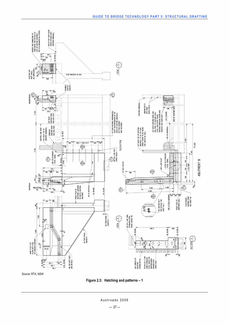
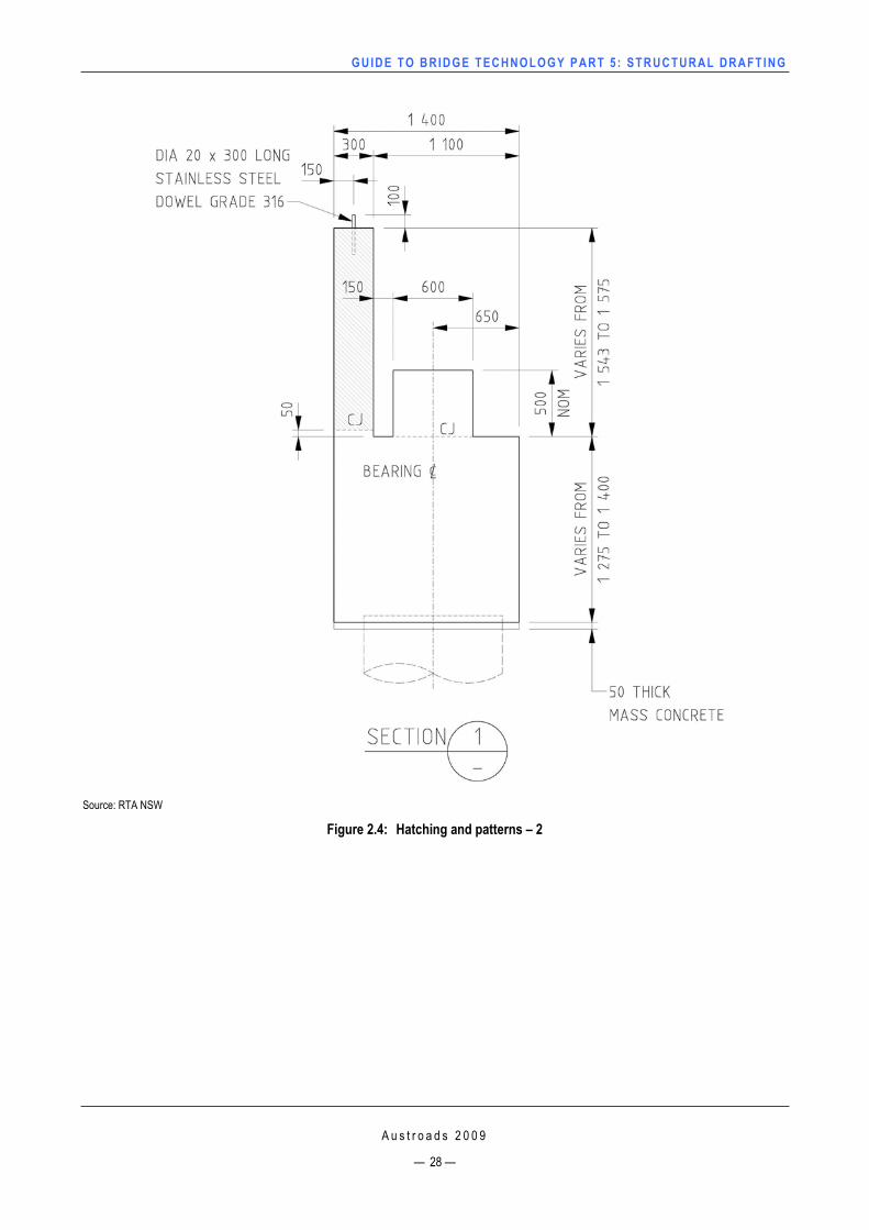
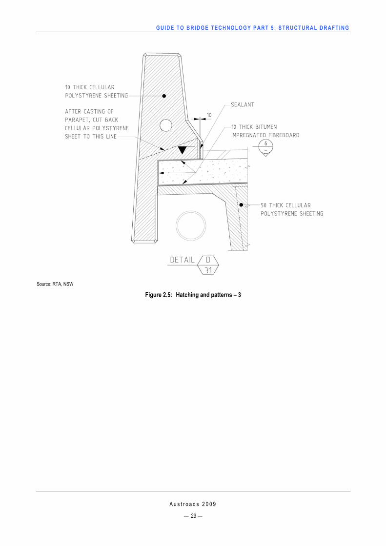
2.8 Symbols and Patterns 2.8.1 PatternsHatching
Hatching is a useful tool when a component is required to standout or be clearly visible. Hatching can be displayed by showing either thin lines or shading over an area. When hatching, consideration about scale, congestion and possible confusion should be taken when drawings are read at an A3 size. (Figure 2.3, Figure 2.4 and Figure 2.5)
Common hatching used in bridge and related structures should be related back to the relative road authority.
Material representation
Material representation can be a useful tool when showing the differences between a number of materials, e.g. mass concrete and reinforced concrete. Material representation can be displayed by showing a material specific pattern over an area. When using patterns, consideration about scale, congestion and possible confusion should be taken when drawings are read at an A3 size.
Common material specific patterns used in bridge and related structures should be related back to the relevant road authority. (Figure 2.3 and Figure 2.5)
GUIDE TO BRIDGE TECHNO LOGY PART 5 : STRUCTURAL DRAFT ING
Source: RTA, NSW
Figure 2.3: Hatching and patterns – 1
A u s t r o a d s 2 0 0 9
— 27 —
GUIDE TO BRIDGE TECHNO LOGY PART 5 : STRUCTURAL DRAFT ING
Source: RTA NSW
Figure 2.4: Hatching and patterns – 2
A u s t r o a d s 2 0 0 9
— 28 —
GUIDE TO BRIDGE TECHNO LOGY PART 5 : STRUCTURAL DRAFT ING
Source: RTA, NSW
Figure 2.5: Hatching and patterns – 3
A u s t r o a d s 2 0 0 9
— 29 —
GUIDE TO BRIDGE TECHNO LOGY PART 5 : STRUCTURAL DRAFT ING
A u s t r o a d s 2 0 0 9
— 30 —
2.8.2 Use of Symbols Reference symbols
When considering the use of reference symbols the following points should be taken into account:
The size of the symbol used shall be no less than the size of text it is placed near and should be easily identifiable when read on an A3 size drawing.
Different symbols shall be used for subsequent references on any drawing.
The reference note shall be located either close to the point of interest, or in the drawing notes for the same drawing.
Notes to be symbol referenced are to be considered only when deemed necessary, e.g. to avoid note repetition, or where space is too confined to allow the note to be clearly displayed.
Surface texture of metals
Where on drawings a component’s surface texture for metal work is required to ensure an acceptable surface finish, the necessary information shall be given by the use of standard symbols and roughness grade numbers.
All symbols shall be in accordance with AS ISO 1302.
2.8.3 WeldingThe necessary information concerning the location, type, size and length of welds in welded joints and whether the welds are made in the shop or on site shall be given on the drawings with the use of standard welding symbols.
All welding symbols shall be in accordance with AS 1101.3 (2005).
2.9 Notes and References Notes on drawings shall be clear and concise with regard to the required information and instructions.
All lettering shall be in upper case except where standard metric abbreviations dictate otherwise.
2.9.1 General Notes or Drawing Specific Notes In the general or drawing specific notes, references to the relevant Australian Standards shall be used. Grade/class of a material or materials shall be noted, e.g. ‘Steel sections shall conform to AS/NZS 3679.1’.
General Notes or Drawing Specific Notes shall be shown on either the structure component drawing or on a designated notes sheet.
The practice of locating General Notes or Drawing Specific Notes will vary depending on the State Authority.
The Roads and Traffic Authority, New South Wales (RTA) has the following requirements:
Each bridge/structure component drawing, or drawing set, shall contain clear and concise general notes relating the required information needed to construct the component being detailed in its entirety. At no such time should a designated notes sheet be created to contain all notes for a complete set of bridge/structure plans.
GUIDE TO BRIDGE TECHNO LOGY PART 5 : STRUCTURAL DRAFT ING
For a component where more than one sheet is required to show adequate details for construction, the general notes are not required to be produced on each subsequent sheet, a note referring to the sheet containing these notes is adequate. e.g. ‘For other General Notes relating to this sheet, see sheet No. X or sheet No. Y’.
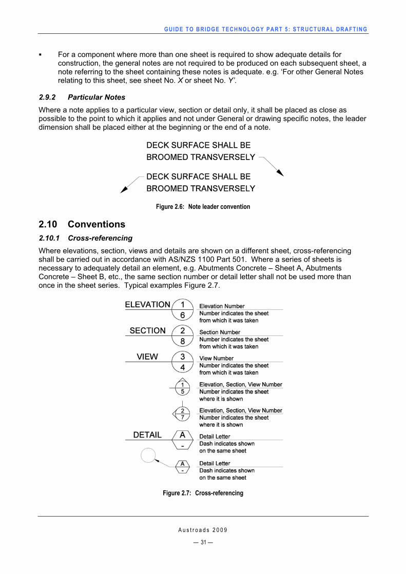
2.9.2 Particular Notes Where a note applies to a particular view, section or detail only, it shall be placed as close as possible to the point to which it applies and not under General or drawing specific notes, the leader dimension shall be placed either at the beginning or the end of a note.
Figure 2.6: Note leader convention
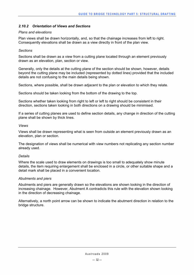
2.10 Conventions2.10.1 Cross-referencingWhere elevations, section, views and details are shown on a different sheet, cross-referencing shall be carried out in accordance with AS/NZS 1100 Part 501. Where a series of sheets is necessary to adequately detail an element, e.g. Abutments Concrete – Sheet A, Abutments Concrete – Sheet B, etc., the same section number or detail letter shall not be used more than once in the sheet series. Typical examples Figure 2.7.
Figure 2.7: Cross-referencing
A u s t r o a d s 2 0 0 9
— 31 —
GUIDE TO BRIDGE TECHNO LOGY PART 5 : STRUCTURAL DRAFT ING
A u s t r o a d s 2 0 0 9
— 32 —
2.10.2 Orientation of Views and Sections Plans and elevations
Plan views shall be drawn horizontally, and, so that the chainage increases from left to right.Consequently elevations shall be drawn as a view directly in front of the plan view.
Sections
Sections shall be drawn as a view from a cutting plane located through an element previously drawn as an elevation, plan, section or view.
Generally, only the details at the cutting plane of the section should be shown, however, details beyond the cutting plane may be included (represented by dotted lines) provided that the included details are not confusing to the main details being shown.
Sections, where possible, shall be drawn adjacent to the plan or elevation to which they relate.
Sections should be taken looking from the bottom of the drawing to the top.
Sections whether taken looking from right to left or left to right should be consistent in their direction, sections taken looking in both directions on a drawing should be minimised.
If a series of cutting planes are used to define section details, any change in direction of the cutting plane shall be shown by thick lines.
Views
Views shall be drawn representing what is seen from outside an element previously drawn as an elevation, plan or section.
The designation of views shall be numerical with view numbers not replicating any section number already used.
Details
Where the scale used to draw elements on drawings is too small to adequately show minute details, the item requiring enlargement shall be enclosed in a circle, or other suitable shape and a detail mark shall be placed in a convenient location.
Abutments and piers
Abutments and piers are generally drawn so the elevations are shown looking in the direction of increasing chainage. However, Abutment A contradicts this rule with the elevation shown looking in the direction of decreasing chainage.
Alternatively, a north point arrow can be shown to indicate the abutment direction in relation to the bridge structure.
GUIDE TO BRIDGE TECHNO LOGY PART 5 : STRUCTURAL DRAFT ING
2.11 Setting Out 2.11.1 Chainage, Compass Bearing, Coordinates General
The geometry of the road defines the shape of the bridge (more particularly the deck). The geometry of the deck therefore must be defined before that of the substructure and footings and/or piles. Road design information and bridge site survey information provide relevant coordinates, alignment data, etc. Generally setting out is carried out by one of two methods:
alignment method (chainage and offset)
a coordinate system (with current technologies, this is the preferred method).
For structures which have a straight alignment, the setting out should be carried out using the control line.
Chainages and offsets or, alternatively, coordinates may be used to locate the centre of elements e.g. spread footings, piles; pier headstocks etc. Dimensions for each element shall be related to the defined location and shall be normal to the element centreline.
Chainage
Chainages, given along the control line, shall be adopted from the road design and/or site survey information provided.
Where possible and practical, chainages for the centrelines of piers, bearings etc., shall be given in metres to the nearest 0.005 metre.
Compass bearing
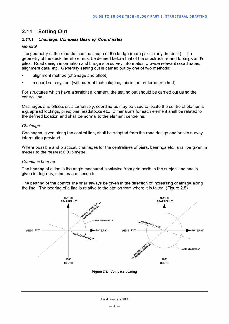
The bearing of a line is the angle measured clockwise from grid north to the subject line and is given in degrees, minutes and seconds.
The bearing of the control line shall always be given in the direction of increasing chainage along the line. The bearing of a line is relative to the station from where it is taken. (Figure 2.8)
Figure 2.8: Compass bearing
A u s t r o a d s 2 0 0 9
— 33 —
GUIDE TO BRIDGE TECHNO LOGY PART 5 : STRUCTURAL DRAFT ING
A u s t r o a d s 2 0 0 9
— 34 —
Coordinates
The coordinate system adopted for a project may be an arbitrary local one, ISG (Integrated Survey Grid), GDA (Geocentric Datum of Australia) or MGA (Map Grid of Australia).
The coordinates are normally quoted in metres to the nearest 0.001 metre. In recording GDA, ISG and MGA coordinates, the Easting value is always placed before the Northing value.
The following procedure is recommended for the listing of coordinates.
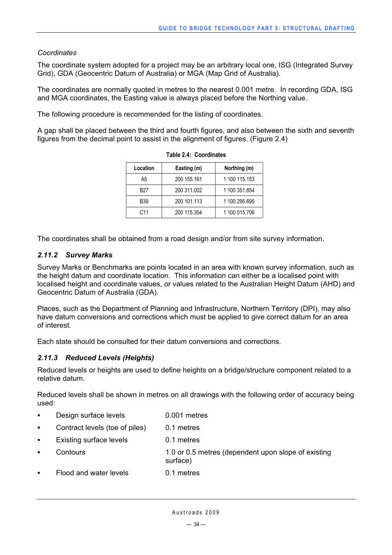
A gap shall be placed between the third and fourth figures, and also between the sixth and seventh figures from the decimal point to assist in the alignment of figures. (Figure 2.4)
Table 2.4: Coordinates
Location Easting (m) Northing (m)
A5 200 155.161 1 100 115.153
B27 200 311.002 1 100 351.854
B39 200 101.113 1 100 295.695
C11 200 115.354 1 100 015.706
The coordinates shall be obtained from a road design and/or from site survey information.
2.11.2 Survey Marks Survey Marks or Benchmarks are points located in an area with known survey information, such as the height datum and coordinate location. This information can either be a localised point with localised height and coordinate values, or values related to the Australian Height Datum (AHD) and Geocentric Datum of Australia (GDA).
Places, such as the Department of Planning and Infrastructure, Northern Territory (DPI), may also have datum conversions and corrections which must be applied to give correct datum for an area of interest.
Each state should be consulted for their datum conversions and corrections.
2.11.3 Reduced Levels (Heights) Reduced levels or heights are used to define heights on a bridge/structure component related to a relative datum.
Reduced levels shall be shown in metres on all drawings with the following order of accuracy being used:
Design surface levels 0.001 metres
Contract levels (toe of piles) 0.1 metres
Existing surface levels 0.1 metres
Contours 1.0 or 0.5 metres (dependent upon slope of existing surface)
Flood and water levels 0.1 metres
GUIDE TO BRIDGE TECHNO LOGY PART 5 : STRUCTURAL DRAFT ING
A u s t r o a d s 2 0 0 9
— 35 —
3 PARTICULAR APPLICATIONS
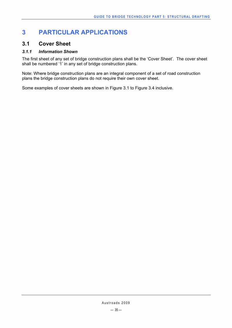
3.1 Cover Sheet 3.1.1 Information Shown The first sheet of any set of bridge construction plans shall be the ‘Cover Sheet’. The cover sheet shall be numbered ‘1’ in any set of bridge construction plans.
Note: Where bridge construction plans are an integral component of a set of road construction plans the bridge construction plans do not require their own cover sheet.
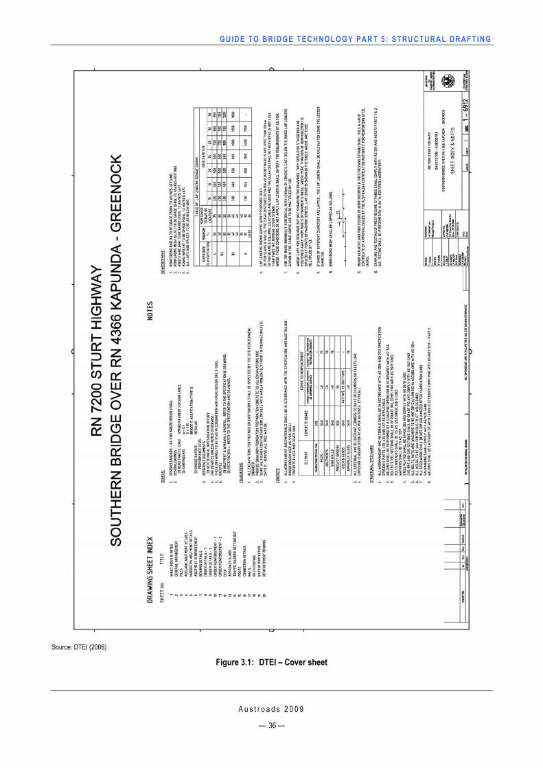
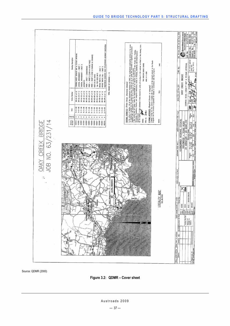
Some examples of cover sheets are shown in Figure 3.1 to Figure 3.4 inclusive.
GUIDE TO BRIDGE TECHNO LOGY PART 5 : STRUCTURAL DRAFT ING
Source: DTEI (2008)
Figure 3.1: DTEI – Cover sheet
A u s t r o a d s 2 0 0 9
— 36 —
GUIDE TO BRIDGE TECHNO LOGY PART 5 : STRUCTURAL DRAFT ING
Source: QDMR (2000)
Figure 3.2: QDMR – Cover sheet
A u s t r o a d s 2 0 0 9
— 37 —
GUIDE TO BRIDGE TECHNO LOGY PART 5 : STRUCTURAL DRAFT ING
Source: RTA NSW (2007)
Figure 3.3: RTA – Cover sheet
A u s t r o a d s 2 0 0 9
— 38 —
GUIDE TO BRIDGE TECHNO LOGY PART 5 : STRUCTURAL DRAFT ING
Source: VicRoads n.d.
Figure 3.4: VicRoads – Cover sheet
A u s t r o a d s 2 0 0 9
— 39 —
GUIDE TO BRIDGE TECHNO LOGY PART 5 : STRUCTURAL DRAFT ING
A u s t r o a d s 2 0 0 9
— 40 —
3.2 General Arrangement 3.2.1 GeneralGeneral Arrangement drawings are an important part of a set of bridge construction plans.
The General Arrangement gives the reader an overall view of what the bridge/structure will appear like once construction has been completed and shall not contain any construction requirement information or construction sequences. (Figure 3.12)
Depending on the complexity of the bridge/structure and the detail required, multiple sheets may be used and titled in accordance with Section 2.6.3 Titles and Sub-titles.
The General Arrangement shall generally contain the following information:
plan view
elevation
typical cross-section
horizontal alignment diagram (if applicable)
vertical alignment diagram (if applicable)
skew diagram (if applicable)
site plan (if applicable)
general notes.
3.2.2 Plan View Plan views are important in showing the reader the location of the bridge/structure and the surrounding site, which may contain utilities, roads, waterways and other points of interest and therefore should show adequate details.
Generally plan views shall contain the following information:
the featured obstacle such as, a watercourse, roadway or railway line
the location of public and private utilities
contours of the existing surface (Section 3.2.3 Contours)
the direction of flow or tidal representation of the watercourse
existing structures and the important reduced levels
the design/control line
the chainages and reduced levels on the control line at the ends of the deck, at each pier centreline and if appropriate at the intersection point between the control line for the bridge/structure and the centreline of the underlying road or railway line
the bearing or radius of the control line for the controlling geometry of the bridge/structure
coordinates for the intersection point between the control line for the bridge/structure and the centreline of the underlying road or railway line
the visible lines of the bridge/structure plan view, (e.g. deck and parapets, barriers, abutment wing walls, approach slabs, etc.)
the outlines of the substructure elements shown in the appropriate line styles
GUIDE TO BRIDGE TECHNO LOGY PART 5 : STRUCTURAL DRAFT ING
A u s t r o a d s 2 0 0 9
— 41 —
the shape and slopes of embankments required
extent of any embankment protection required
extent of any channel excavation required
horizontal clearances as required (e.g. distance between new structure and existing structure)
the location of any vertical clearance referenced from the elevation
the compass direction of true north indicated by the use of a north point.
Contours
A contour is a line derived from the joining of points at the same height above a datum on an existing surface.
Contours shall be drawn as uniform lines, except under a bridge/structure where the line shall then be shown as dashed lines. The line thickness shall be shown so as not to distract from the bridge/structure elements.
The level annotation of each contour shall be shown, at a minimum, once at the end of the contour; however more level annotations may be shown on the same contour line for easier reading if deemed necessary due to the complexity of the contour.
The contour intervals should be determined to suit the slope of the existing surface, however for very steep grades the intervals shall not exceed 1.0 metre and for very flat grades the intervals shall be no more than 0.25 metres.
3.2.3 ElevationElevations are important in showing the reader the location in height of the bridge/structure and the level of the surrounding site, the locations of roads, waterways and other points of interest and therefore should show adequate details. The elevation should be placed as a projection above or below the plan, depending on the road authority method of projection.
Generally elevations shall contain the following information:
the approximate profile of the existing surface directly below the control line, including the featured obstacle such as, a watercourse, road or railway line
the normal water level or stream condition (e.g. normally dry)
the calculated high flood level – either or both 1 in 100 year ARI and 1 in 2000 ARI values depending on client requirements. If a reported high flood level is available, this should also be added along with the date of occurrence
if required the mean high springs and mean low springs for tidal waterways (navigational clearances must then be shown – calculated from mean high springs)
the visible lines of the bridge/structure as viewed from the side, (e.g. deck and parapets, barriers, abutment wing walls, piers, etc.)
the outlines of hidden elements shown in the appropriate line styles (e.g. piles, approach slabs, etc.)
dimensions showing critical lengths (e.g. the number and length of spans, overall length of deck, etc.)
GUIDE TO BRIDGE TECHNO LOGY PART 5 : STRUCTURAL DRAFT ING
A u s t r o a d s 2 0 0 9
— 42 —
the longitudinal grade (e.g. 0.5%), if the deck slope is uniform, or, if a vertical curve a reduced level shall be shown
vertical and horizontal clearances for bridges over roadways and/or railway lines including an approximate reduced level at the intersection point between the control line and the centreline of the underlying road or railway line
form and extent of any embankments and any required embankment protection above or below the existing surface level
contract levels of all footings or piles
bearing movements (e.g. fixed, free, sliding, etc.), and expansion joints
chainages, existing surface levels and design surface levels at the end of deck and at pier centrelines on the control line in a datum block beneath the elevation
to/from showing the nearest major towns in both directions from the bridge/structure.
3.2.4 Typical Cross-section A typical cross-section is important in showing the type of bridge/structure detailed in the set of bridge construction plans. The section should be drawn in the direction of increasing chainage, from left to right.
Generally typical cross-sections shall contain the following information:
the type of girder/superstructure elements
deck thickness, parapets/barrier railing (overall height from the wearing surface shall be shown)
type and thickness of the wearing surface
utilities or any special features
cross fall or super elevation (shown as a percentage on an arrow point down the grade).
the control line
dimensions showing critical widths (e.g. clear distance between parapets/barriers, clear distance from control line to parapets/barriers, clear distance of footways, etc.)
indication of orientation with respect to stream flow or compass point (e.g. upstream –downstream, north – south, etc.).
3.2.5 Vertical and Horizontal Alignment Diagrams Vertical and horizontal alignment diagrams shall be shown when a grade on a vertical alignment or a constant bearing on a horizontal alignment are not constant, and shall directly relate to the bridge/structure control line (Figure 3.5 and Figure 3.6).
Generally vertical alignment diagrams shall contain the following information:
the geometry of the curve (e.g. hog or sag curve)
the length of the curve
the grades of the road at each end of the curve (VTP)
the chainage and reduced level at each end of the curve (VTP)
the chainage and reduced level of the intersection point of each grade (VIP)
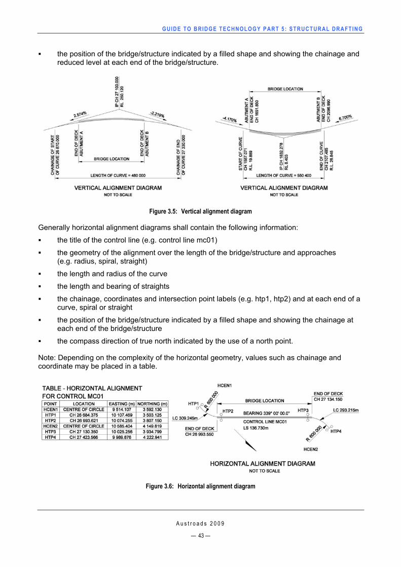
GUIDE TO BRIDGE TECHNO LOGY PART 5 : STRUCTURAL DRAFT ING
the position of the bridge/structure indicated by a filled shape and showing the chainage and reduced level at each end of the bridge/structure.
Figure 3.5: Vertical alignment diagram
Generally horizontal alignment diagrams shall contain the following information:
the title of the control line (e.g. control line mc01)
the geometry of the alignment over the length of the bridge/structure and approaches (e.g. radius, spiral, straight)
the length and radius of the curve
the length and bearing of straights
the chainage, coordinates and intersection point labels (e.g. htp1, htp2) and at each end of a curve, spiral or straight
the position of the bridge/structure indicated by a filled shape and showing the chainage at each end of the bridge/structure
the compass direction of true north indicated by the use of a north point.
Note: Depending on the complexity of the horizontal geometry, values such as chainage and coordinate may be placed in a table.
Figure 3.6: Horizontal alignment diagram
A u s t r o a d s 2 0 0 9
— 43 —
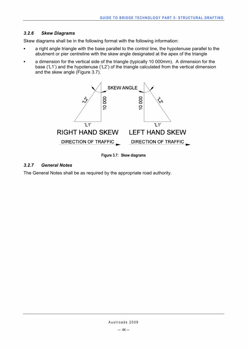
GUIDE TO BRIDGE TECHNO LOGY PART 5 : STRUCTURAL DRAFT ING
3.2.6 Skew Diagrams Skew diagrams shall be in the following format with the following information:
a right angle triangle with the base parallel to the control line, the hypotenuse parallel to the abutment or pier centreline with the skew angle designated at the apex of the triangle
a dimension for the vertical side of the triangle (typically 10 000mm). A dimension for the base (‘L1’) and the hypotenuse (‘L2’) of the triangle calculated from the vertical dimension and the skew angle (Figure 3.7).
Figure 3.7: Skew diagrams
3.2.7 General Notes The General Notes shall be as required by the appropriate road authority.
A u s t r o a d s 2 0 0 9
— 44 —
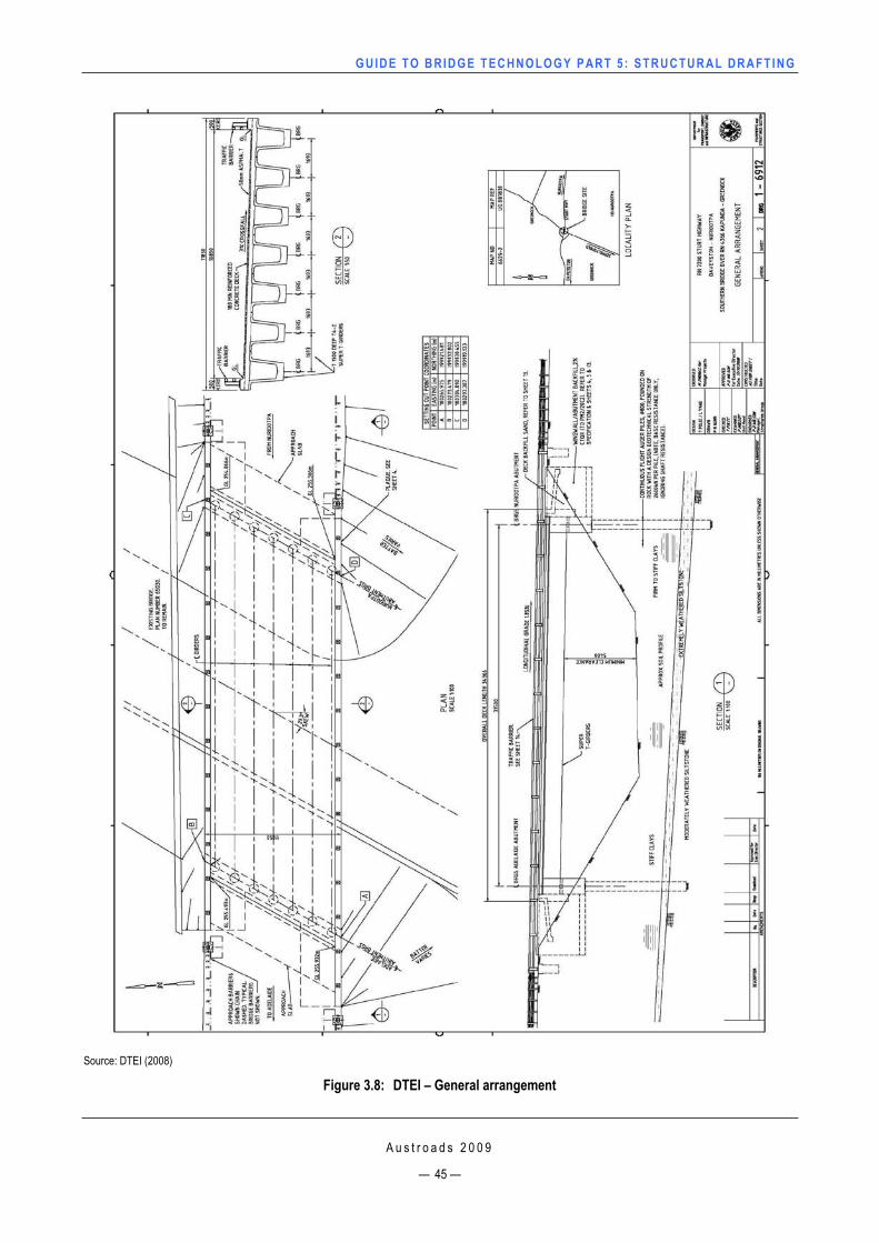
GUIDE TO BRIDGE TECHNO LOGY PART 5 : STRUCTURAL DRAFT ING
Source: DTEI (2008)
Figure 3.8: DTEI – General arrangement
A u s t r o a d s 2 0 0 9
— 45 —
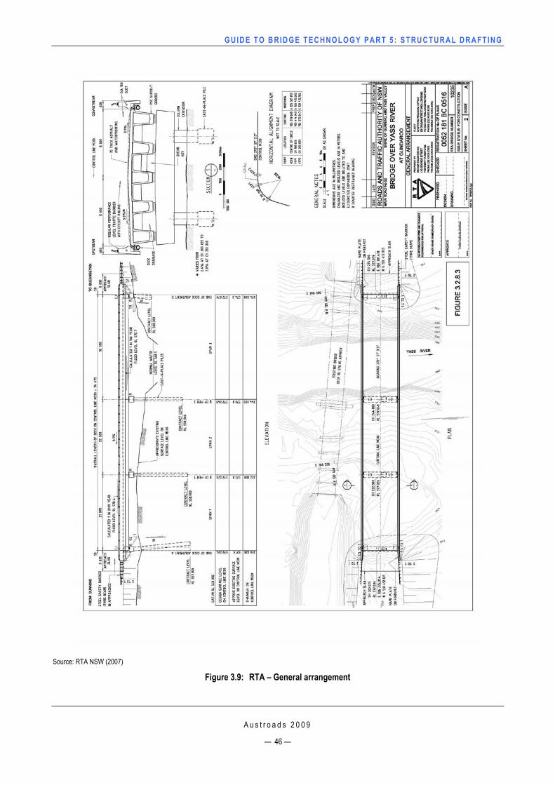
GUIDE TO BRIDGE TECHNO LOGY PART 5 : STRUCTURAL DRAFT ING
Source: RTA NSW (2007)
Figure 3.9: RTA – General arrangement
A u s t r o a d s 2 0 0 9
— 46 —
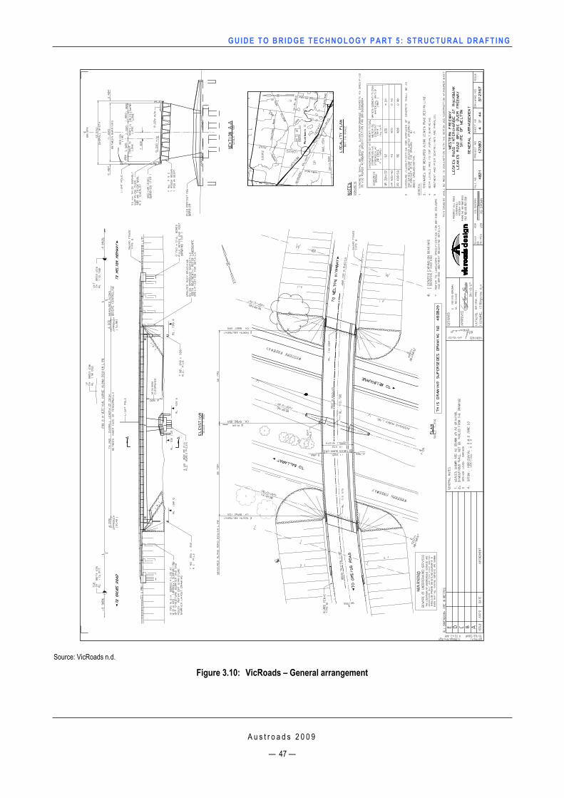
GUIDE TO BRIDGE TECHNO LOGY PART 5 : STRUCTURAL DRAFT ING
A u s t r o a d s 2 0 0 9
— 47 —
Source: VicRoads n.d.
Figure 3.10: VicRoads – General arrangement
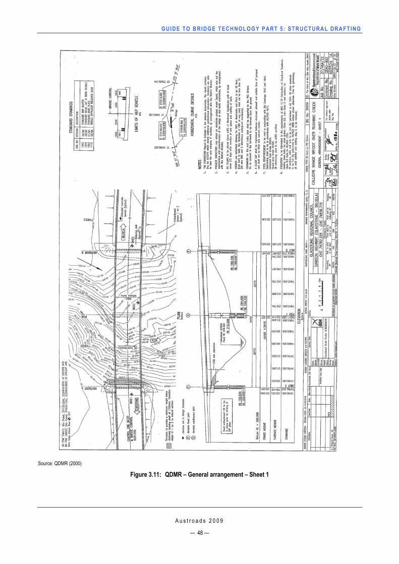
GUIDE TO BRIDGE TECHNO LOGY PART 5 : STRUCTURAL DRAFT ING
Source: QDMR (2000)
Figure 3.11: QDMR – General arrangement – Sheet 1
A u s t r o a d s 2 0 0 9
— 48 —
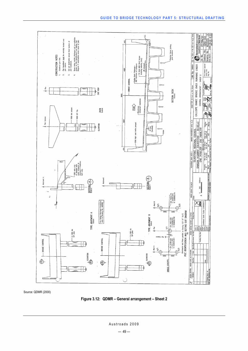
GUIDE TO BRIDGE TECHNO LOGY PART 5 : STRUCTURAL DRAFT ING
Source: QDMR (2000)
Figure 3.12: QDMR – General arrangement – Sheet 2
A u s t r o a d s 2 0 0 9
— 49 —
GUIDE TO BRIDGE TECHNO LOGY PART 5 : STRUCTURAL DRAFT ING
A u s t r o a d s 2 0 0 9
— 50 —
3.3 Footings and Piles 3.3.1 GeneralVarious types of structural elements are used in bridge construction to transfer loads to the foundation material, such as the following:
piles
spread footings
rock anchors.
These elements can also be combined such as piles and spread footings, which when designed will form the base element to support the structure above.
Footing, spread footing and pile layout drawings shall be shown in a set of bridge construction plans, showing the correct setting out, orientation and plan size of all elements. The layout will also show the locations of any test piles (Figure 3.13).
Geotechnical information
Test bores for foundations are taken at nominated locations on bridge sites to establish the type and strength of the foundation material. The information is shown by the drilling contractor in a borehole log.
As a rule at least one borehole would be taken at each pier and abutment location; however this process may vary from one site to the next.
If required or preferred, the locations of the boreholes may be shown on the plan view of a General Arrangement drawing.
As part of a set of bridge construction plans, the borehole log shall be referred to as a reference, either on the pile/footing drawings or on the Cover Sheet.
3.3.2 PilesVarious types of piles are used in bridge construction, such as:
Driven piles
Cast-in-place/drilled piles.
Driven piles
Driven piles are generally prefabricated members made from various types of material, such as, steel (‘H’ piles, tubular piles), concrete (precast reinforced concrete, prestressed reinforced concrete), and timber in some cases. Driven piles also come in various shapes, such as round, square, octagonal, and shaped (e.g. ‘H’ pile).
A separate drawing for the fabricated members shall be added as part of the set of bridge construction plans and shall contain all relevant information required for the fabrication of each member.
Where piles are required to be spliced, the minimum depth below ground level to the splice shall be clearly shown on the drawings.
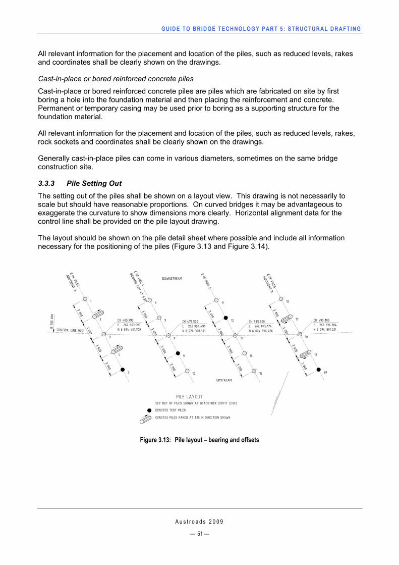
GUIDE TO BRIDGE TECHNO LOGY PART 5 : STRUCTURAL DRAFT ING
All relevant information for the placement and location of the piles, such as reduced levels, rakes and coordinates shall be clearly shown on the drawings.
Cast-in-place or bored reinforced concrete piles
Cast-in-place or bored reinforced concrete piles are piles which are fabricated on site by first boring a hole into the foundation material and then placing the reinforcement and concrete. Permanent or temporary casing may be used prior to boring as a supporting structure for the foundation material.
All relevant information for the placement and location of the piles, such as reduced levels, rakes, rock sockets and coordinates shall be clearly shown on the drawings.
Generally cast-in-place piles can come in various diameters, sometimes on the same bridge construction site.
3.3.3 Pile Setting Out The setting out of the piles shall be shown on a layout view. This drawing is not necessarily to scale but should have reasonable proportions. On curved bridges it may be advantageous to exaggerate the curvature to show dimensions more clearly. Horizontal alignment data for the control line shall be provided on the pile layout drawing.
The layout should be shown on the pile detail sheet where possible and include all information necessary for the positioning of the piles (Figure 3.13 and Figure 3.14).
Figure 3.13: Pile layout – bearing and offsets
A u s t r o a d s 2 0 0 9
— 51 —
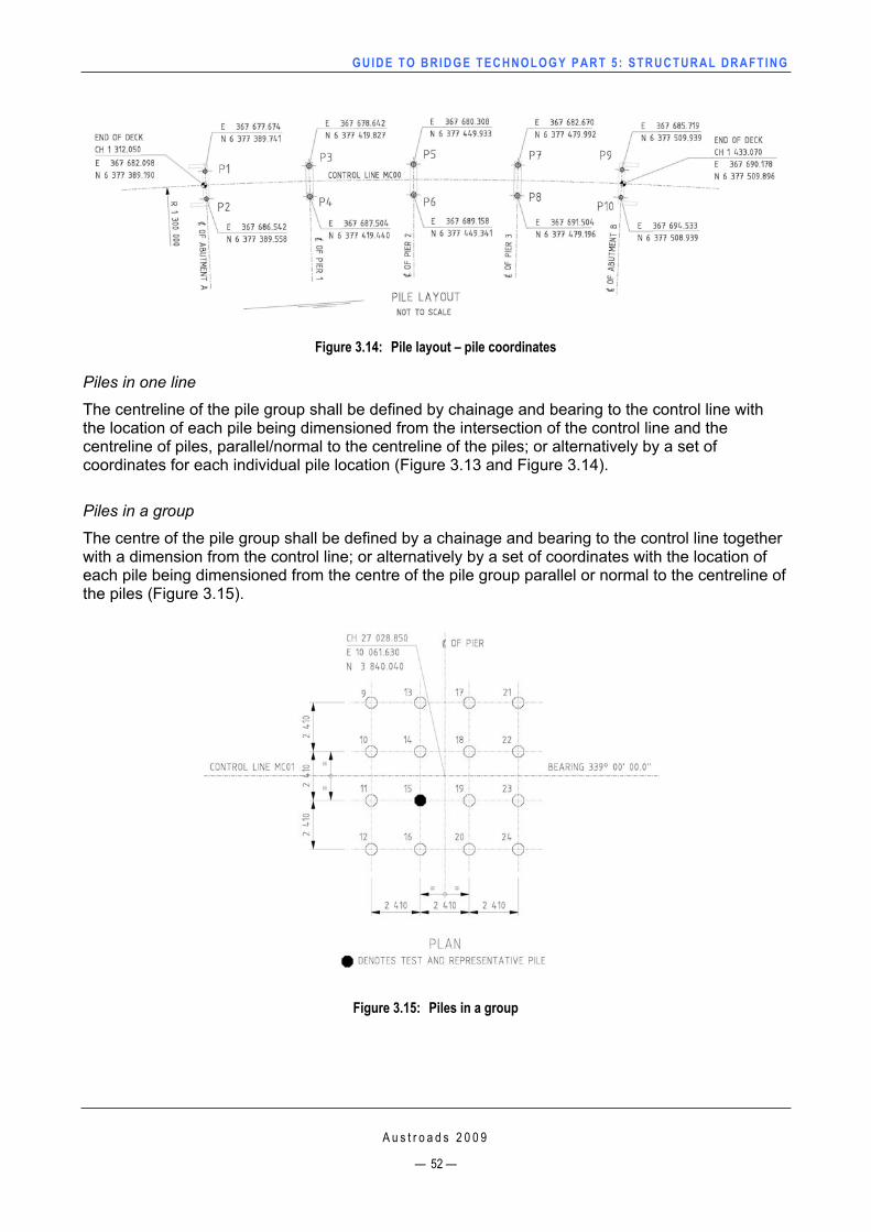
GUIDE TO BRIDGE TECHNO LOGY PART 5 : STRUCTURAL DRAFT ING
Figure 3.14: Pile layout – pile coordinates
Piles in one line
The centreline of the pile group shall be defined by chainage and bearing to the control line with the location of each pile being dimensioned from the intersection of the control line and the centreline of piles, parallel/normal to the centreline of the piles; or alternatively by a set of coordinates for each individual pile location (Figure 3.13 and Figure 3.14).
Piles in a group
The centre of the pile group shall be defined by a chainage and bearing to the control line together with a dimension from the control line; or alternatively by a set of coordinates with the location of each pile being dimensioned from the centre of the pile group parallel or normal to the centreline of the piles (Figure 3.15).
Figure 3.15: Piles in a group
A u s t r o a d s 2 0 0 9
— 52 —
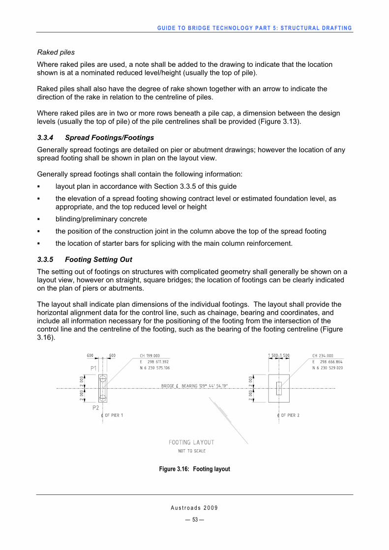
GUIDE TO BRIDGE TECHNO LOGY PART 5 : STRUCTURAL DRAFT ING
Raked piles
Where raked piles are used, a note shall be added to the drawing to indicate that the location shown is at a nominated reduced level/height (usually the top of pile).
Raked piles shall also have the degree of rake shown together with an arrow to indicate the direction of the rake in relation to the centreline of piles.
Where raked piles are in two or more rows beneath a pile cap, a dimension between the design levels (usually the top of pile) of the pile centrelines shall be provided (Figure 3.13).
3.3.4 Spread Footings/Footings Generally spread footings are detailed on pier or abutment drawings; however the location of any spread footing shall be shown in plan on the layout view.
Generally spread footings shall contain the following information:
layout plan in accordance with Section 3.3.5 of this guide
the elevation of a spread footing showing contract level or estimated foundation level, as appropriate, and the top reduced level or height
blinding/preliminary concrete
the position of the construction joint in the column above the top of the spread footing
the location of starter bars for splicing with the main column reinforcement.
3.3.5 Footing Setting Out The setting out of footings on structures with complicated geometry shall generally be shown on a layout view, however on straight, square bridges; the location of footings can be clearly indicated on the plan of piers or abutments.
The layout shall indicate plan dimensions of the individual footings. The layout shall provide the horizontal alignment data for the control line, such as chainage, bearing and coordinates, and include all information necessary for the positioning of the footing from the intersection of the control line and the centreline of the footing, such as the bearing of the footing centreline (Figure3.16).
Figure 3.16: Footing layout
A u s t r o a d s 2 0 0 9
— 53 —
GUIDE TO BRIDGE TECHNO LOGY PART 5 : STRUCTURAL DRAFT ING
A u s t r o a d s 2 0 0 9
— 54 —
The layout does not necessarily need to be to scale, however it should be reasonably proportioned. On curved bridges it may be advantageous to exaggerate the curvature in order that dimensions may be shown more clearly.
3.3.6 Rock Anchors The location of rock anchors should generally be shown in the layout view. Where rock anchors are used to tie back walls and abutments, locations shall be shown on an elevation and any other views necessary to clearly show angles, etc.
Generally rock anchors shall contain the following information:
the location of test anchors
an elevation showing:
— anchorage and anchorage recess — bonded length (for primary grouting) — free length (for secondary grouting) — depth of drilled holes, e.g. 500 mm below end of anchor — bore hole diameter and length — sheathing and extent of sheathing
a cross-section showing:
— location and size of pipe through pile or footing.
3.4 Concrete Detailing 3.4.1 GeneralLine work on drawing should generally be in accordance with Table 3.1 in AS 1100 Part 101. Variations on the theme may be allowed according to the application.
Concrete detail drawings should show the physical dimensions and reduced levels of a concrete structure. It is important that sufficient information is shown to enable formwork to be built and erected and concrete quantities to be easily calculated.
Formed holes, cast-in metal work, construction joints and any necessary layers of mass concrete shall be shown.
General notes
General notes applicable to concrete detail sheets will cover such information as concrete exposure classification, concrete strength and any other applicable notes relating to the concrete structure.
3.4.2 Holes in Concrete, Cast-in Items Holes in concrete
Concrete structures may require some form of hole to be formed, cored or drilled, depending on their application.
Formed holes are cast at the time of placing the concrete either by using some form of sacrificial material, such as a polystyrene block, or by using some type of hollow pipe as a permanent formwork. The location of the formed holes shall be sufficiently dimensioned to enable their correct positioning inside the formwork.
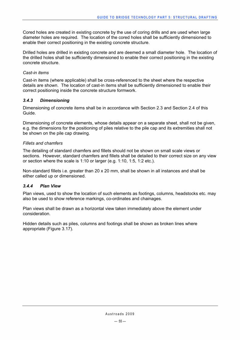
GUIDE TO BRIDGE TECHNO LOGY PART 5 : STRUCTURAL DRAFT ING
A u s t r o a d s 2 0 0 9
— 55 —
Cored holes are created in existing concrete by the use of coring drills and are used when large diameter holes are required. The location of the cored holes shall be sufficiently dimensioned to enable their correct positioning in the existing concrete structure.
Drilled holes are drilled in existing concrete and are deemed a small diameter hole. The location of the drilled holes shall be sufficiently dimensioned to enable their correct positioning in the existing concrete structure.
Cast-in items
Cast-in items (where applicable) shall be cross-referenced to the sheet where the respective details are shown. The location of cast-in items shall be sufficiently dimensioned to enable their correct positioning inside the concrete structure formwork.
3.4.3 Dimensioning Dimensioning of concrete items shall be in accordance with Section 2.3 and Section 2.4 of this Guide.
Dimensioning of concrete elements, whose details appear on a separate sheet, shall not be given, e.g. the dimensions for the positioning of piles relative to the pile cap and its extremities shall not be shown on the pile cap drawing.
Fillets and chamfers
The detailing of standard chamfers and fillets should not be shown on small scale views or sections. However, standard chamfers and fillets shall be detailed to their correct size on any view or section where the scale is 1:10 or larger (e.g. 1:10, 1:5, 1:2 etc.).
Non-standard fillets i.e. greater than 20 x 20 mm, shall be shown in all instances and shall be either called up or dimensioned.
3.4.4 Plan View Plan views, used to show the location of such elements as footings, columns, headstocks etc. may also be used to show reference markings, co-ordinates and chainages.
Plan views shall be drawn as a horizontal view taken immediately above the element under consideration.
Hidden details such as piles, columns and footings shall be shown as broken lines where appropriate (Figure 3.17).
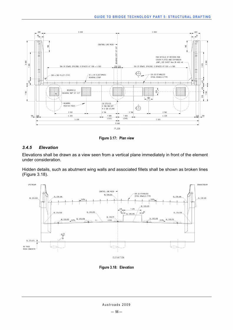
GUIDE TO BRIDGE TECHNO LOGY PART 5 : STRUCTURAL DRAFT ING
Figure 3.17: Plan view
3.4.5 ElevationElevations shall be drawn as a view seen from a vertical plane immediately in front of the element under consideration.
Hidden details, such as abutment wing walls and associated fillets shall be shown as broken lines (Figure 3.18).
Figure 3.18: Elevation
A u s t r o a d s 2 0 0 9
— 56 —
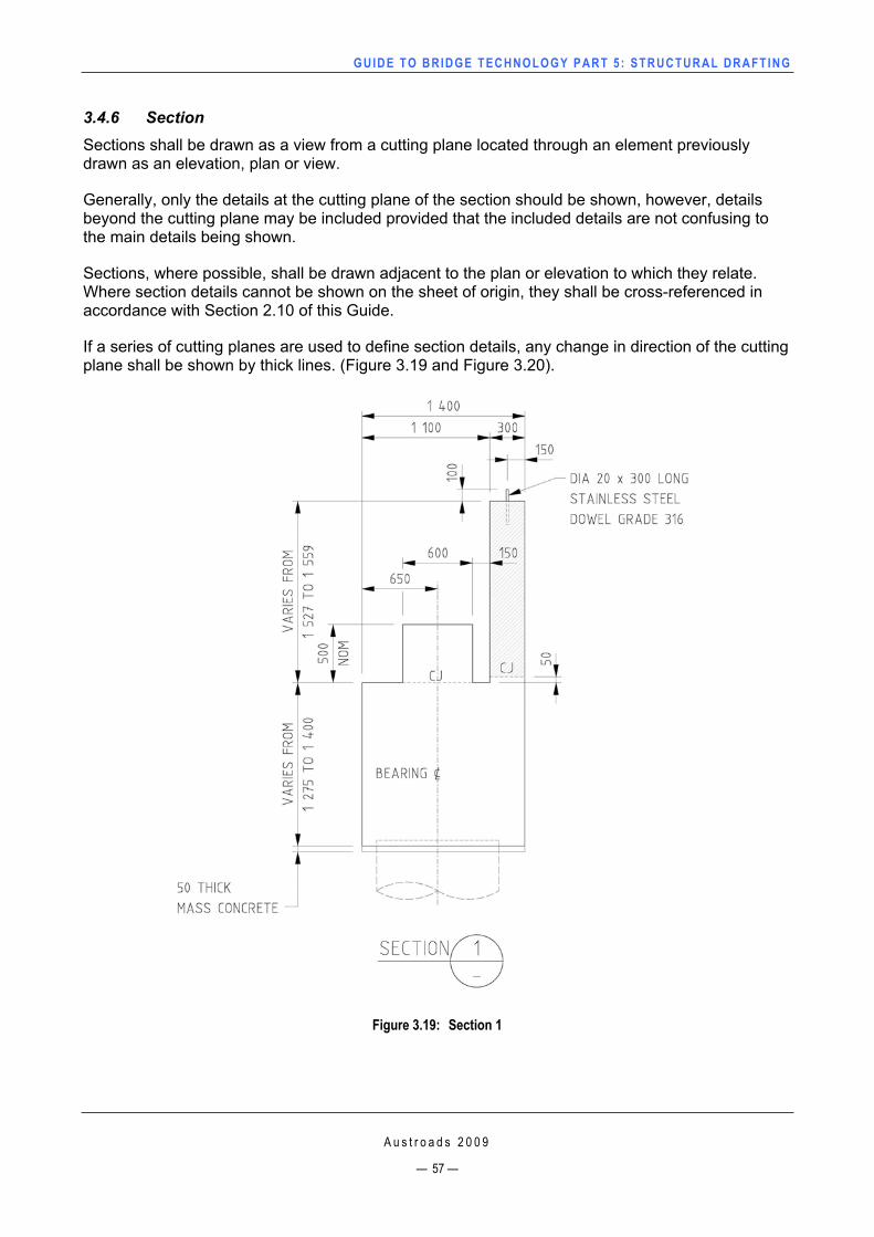
GUIDE TO BRIDGE TECHNO LOGY PART 5 : STRUCTURAL DRAFT ING
3.4.6 SectionSections shall be drawn as a view from a cutting plane located through an element previously drawn as an elevation, plan or view.
Generally, only the details at the cutting plane of the section should be shown, however, details beyond the cutting plane may be included provided that the included details are not confusing to the main details being shown.
Sections, where possible, shall be drawn adjacent to the plan or elevation to which they relate. Where section details cannot be shown on the sheet of origin, they shall be cross-referenced in accordance with Section 2.10 of this Guide.
If a series of cutting planes are used to define section details, any change in direction of the cutting plane shall be shown by thick lines. (Figure 3.19 and Figure 3.20).
Figure 3.19: Section 1
A u s t r o a d s 2 0 0 9
— 57 —
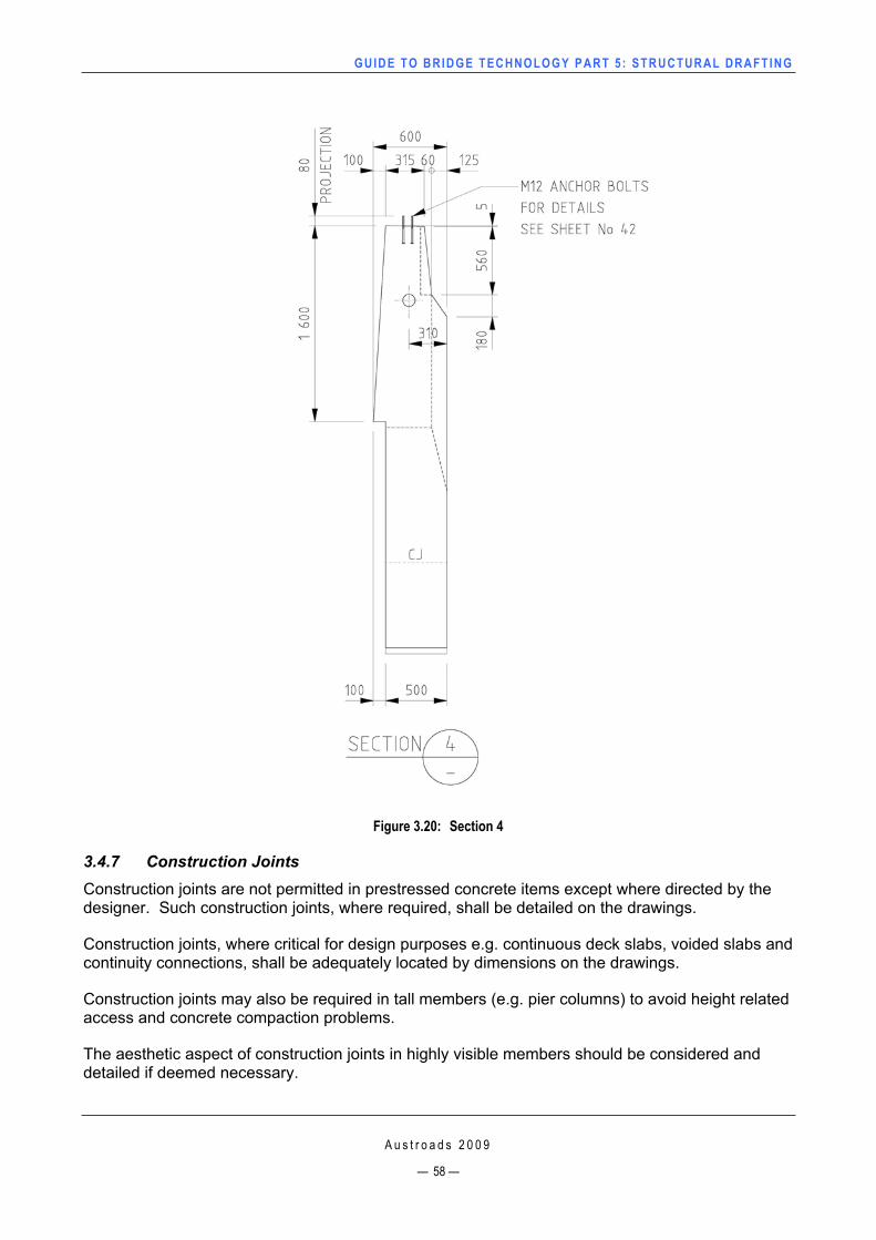
GUIDE TO BRIDGE TECHNO LOGY PART 5 : STRUCTURAL DRAFT ING
Figure 3.20: Section 4
3.4.7 Construction Joints Construction joints are not permitted in prestressed concrete items except where directed by the designer. Such construction joints, where required, shall be detailed on the drawings.
Construction joints, where critical for design purposes e.g. continuous deck slabs, voided slabs and continuity connections, shall be adequately located by dimensions on the drawings.
Construction joints may also be required in tall members (e.g. pier columns) to avoid height related access and concrete compaction problems.
The aesthetic aspect of construction joints in highly visible members should be considered and detailed if deemed necessary.
A u s t r o a d s 2 0 0 9
— 58 —
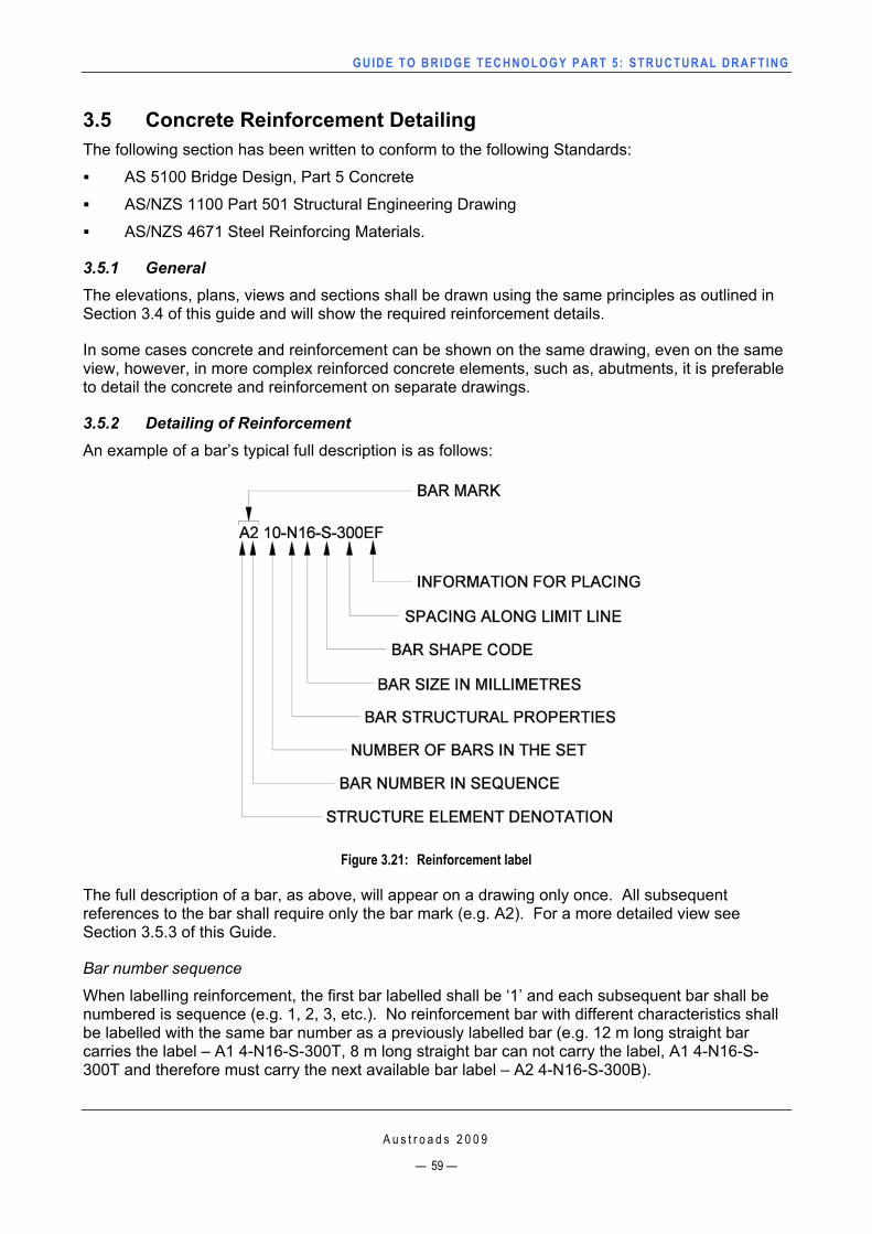
GUIDE TO BRIDGE TECHNO LOGY PART 5 : STRUCTURAL DRAFT ING
3.5 Concrete Reinforcement Detailing The following section has been written to conform to the following Standards:
AS 5100 Bridge Design, Part 5 Concrete
AS/NZS 1100 Part 501 Structural Engineering Drawing
AS/NZS 4671 Steel Reinforcing Materials.
3.5.1 GeneralThe elevations, plans, views and sections shall be drawn using the same principles as outlined in Section 3.4 of this guide and will show the required reinforcement details.
In some cases concrete and reinforcement can be shown on the same drawing, even on the same view, however, in more complex reinforced concrete elements, such as, abutments, it is preferable to detail the concrete and reinforcement on separate drawings.
3.5.2 Detailing of Reinforcement An example of a bar’s typical full description is as follows:
Figure 3.21: Reinforcement label
The full description of a bar, as above, will appear on a drawing only once. All subsequent references to the bar shall require only the bar mark (e.g. A2). For a more detailed view see Section 3.5.3 of this Guide.
Bar number sequence
When labelling reinforcement, the first bar labelled shall be ‘1’ and each subsequent bar shall be numbered is sequence (e.g. 1, 2, 3, etc.). No reinforcement bar with different characteristics shall be labelled with the same bar number as a previously labelled bar (e.g. 12 m long straight bar carries the label – A1 4-N16-S-300T, 8 m long straight bar can not carry the label, A1 4-N16-S-300T and therefore must carry the next available bar label – A2 4-N16-S-300B).
A u s t r o a d s 2 0 0 9
— 59 —
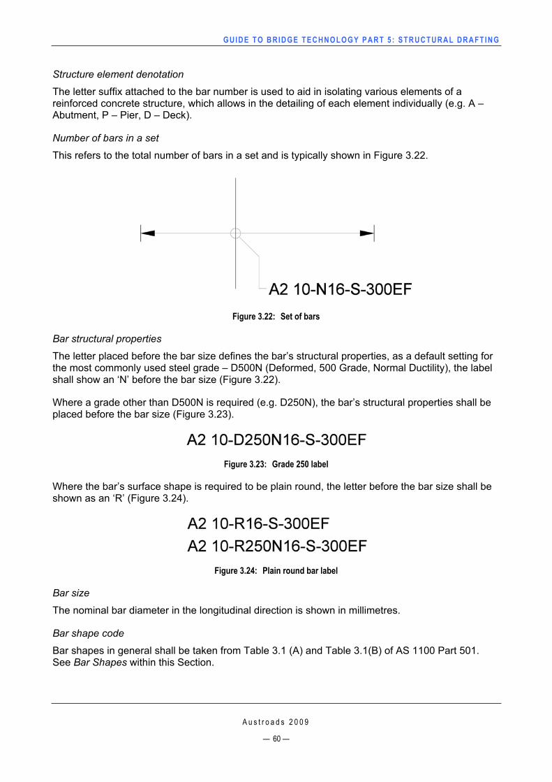
GUIDE TO BRIDGE TECHNO LOGY PART 5 : STRUCTURAL DRAFT ING
Structure element denotation
The letter suffix attached to the bar number is used to aid in isolating various elements of a reinforced concrete structure, which allows in the detailing of each element individually (e.g. A – Abutment, P – Pier, D – Deck).
Number of bars in a set
This refers to the total number of bars in a set and is typically shown in Figure 3.22.
Figure 3.22: Set of bars
Bar structural properties
The letter placed before the bar size defines the bar’s structural properties, as a default setting for the most commonly used steel grade – D500N (Deformed, 500 Grade, Normal Ductility), the label shall show an ‘N’ before the bar size (Figure 3.22).
Where a grade other than D500N is required (e.g. D250N), the bar’s structural properties shall be placed before the bar size (Figure 3.23).
Figure 3.23: Grade 250 label
Where the bar’s surface shape is required to be plain round, the letter before the bar size shall be shown as an ‘R’ (Figure 3.24).
Figure 3.24: Plain round bar label
Bar size
The nominal bar diameter in the longitudinal direction is shown in millimetres.
Bar shape code
Bar shapes in general shall be taken from Table 3.1 (A) and Table 3.1(B) of AS 1100 Part 501. See Bar Shapes within this Section.
A u s t r o a d s 2 0 0 9
— 60 —
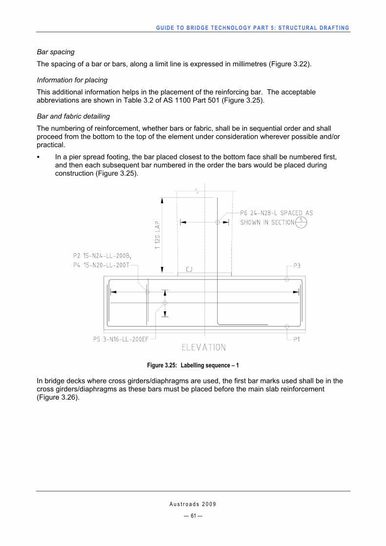
GUIDE TO BRIDGE TECHNO LOGY PART 5 : STRUCTURAL DRAFT ING
Bar spacing
The spacing of a bar or bars, along a limit line is expressed in millimetres (Figure 3.22).
Information for placing
This additional information helps in the placement of the reinforcing bar. The acceptable abbreviations are shown in Table 3.2 of AS 1100 Part 501 (Figure 3.25).
Bar and fabric detailing
The numbering of reinforcement, whether bars or fabric, shall be in sequential order and shall proceed from the bottom to the top of the element under consideration wherever possible and/or practical.
In a pier spread footing, the bar placed closest to the bottom face shall be numbered first, and then each subsequent bar numbered in the order the bars would be placed during construction (Figure 3.25).
Figure 3.25: Labelling sequence – 1
In bridge decks where cross girders/diaphragms are used, the first bar marks used shall be in the cross girders/diaphragms as these bars must be placed before the main slab reinforcement (Figure 3.26).
A u s t r o a d s 2 0 0 9
— 61 —
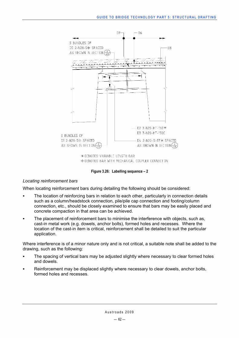
GUIDE TO BRIDGE TECHNO LOGY PART 5 : STRUCTURAL DRAFT ING
Figure 3.26: Labelling sequence – 2
Locating reinforcement bars
When locating reinforcement bars during detailing the following should be considered:
The location of reinforcing bars in relation to each other, particularly in connection details such as a column/headstock connection, pile/pile cap connection and footing/column connection, etc., should be closely examined to ensure that bars may be easily placed and concrete compaction in that area can be achieved.
The placement of reinforcement bars to minimise the interference with objects, such as, cast-in metal work (e.g. dowels, anchor bolts), formed holes and recesses. Where the location of the cast-in item is critical, reinforcement shall be detailed to suit the particular application.
Where interference is of a minor nature only and is not critical, a suitable note shall be added to the drawing, such as the following:
The spacing of vertical bars may be adjusted slightly where necessary to clear formed holes and dowels.
Reinforcement may be displaced slightly where necessary to clear dowels, anchor bolts, formed holes and recesses.
A u s t r o a d s 2 0 0 9
— 62 —
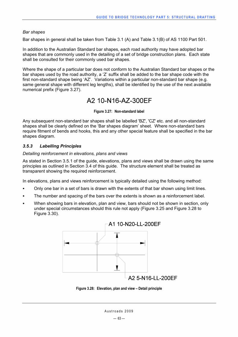
GUIDE TO BRIDGE TECHNO LOGY PART 5 : STRUCTURAL DRAFT ING
Bar shapes
Bar shapes in general shall be taken from Table 3.1 (A) and Table 3.1(B) of AS 1100 Part 501.
In addition to the Australian Standard bar shapes, each road authority may have adopted bar shapes that are commonly used in the detailing of a set of bridge construction plans. Each state shall be consulted for their commonly used bar shapes.
Where the shape of a particular bar does not conform to the Australian Standard bar shapes or the bar shapes used by the road authority, a ‘Z’ suffix shall be added to the bar shape code with the first non-standard shape being ‘AZ’. Variations within a particular non-standard bar shape (e.g. same general shape with different leg lengths), shall be identified by the use of the next available numerical prefix (Figure 3.27).
Figure 3.27: Non-standard label
Any subsequent non-standard bar shapes shall be labelled 'BZ', 'CZ' etc. and all non-standard shapes shall be clearly defined on the ‘Bar shapes diagram’ sheet. Where non-standard bars require fitment of bends and hooks, this and any other special feature shall be specified in the bar shapes diagram.
3.5.3 Labelling Principles Detailing reinforcement in elevations, plans and views
As stated in Section 3.5.1 of the guide, elevations, plans and views shall be drawn using the same principles as outlined in Section 3.4 of this guide. The structure element shall be treated as transparent showing the required reinforcement.
In elevations, plans and views reinforcement is typically detailed using the following method:
Only one bar in a set of bars is drawn with the extents of that bar shown using limit lines.
The number and spacing of the bars over the extents is shown as a reinforcement label.
When showing bars in elevation, plan and view, bars should not be shown in section, only under special circumstances should this rule not apply (Figure 3.25 and Figure 3.28 to Figure 3.30).
Figure 3.28: Elevation, plan and view – Detail principle
A u s t r o a d s 2 0 0 9
— 63 —
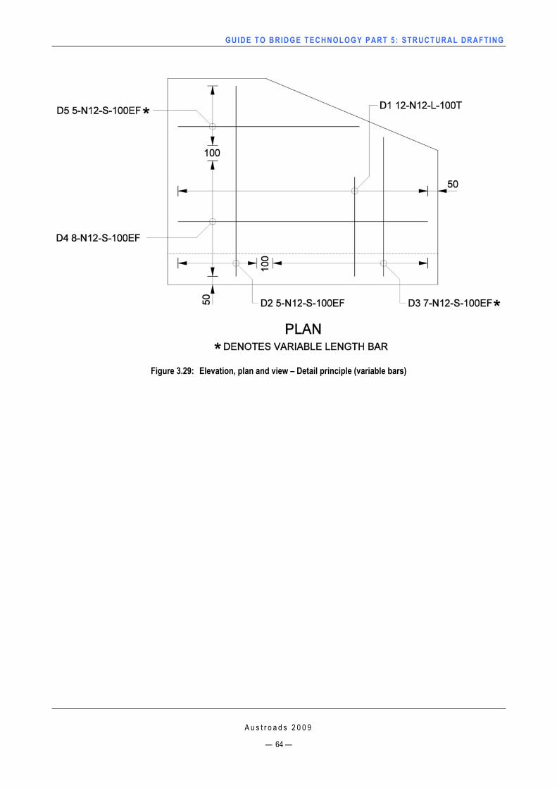
GUIDE TO BRIDGE TECHNO LOGY PART 5 : STRUCTURAL DRAFT ING
Figure 3.29: Elevation, plan and view – Detail principle (variable bars)
A u s t r o a d s 2 0 0 9
— 64 —
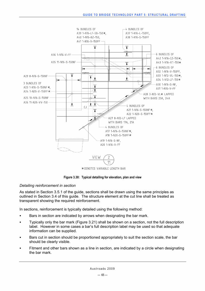
GUIDE TO BRIDGE TECHNO LOGY PART 5 : STRUCTURAL DRAFT ING
Figure 3.30: Typical detailing for elevation, plan and view
Detailing reinforcement in section
As stated in Section 3.5.1 of the guide, sections shall be drawn using the same principles as outlined in Section 3.4 of this guide. The structure element at the cut line shall be treated as transparent showing the required reinforcement.
In sections, reinforcement is typically detailed using the following method:
Bars in section are indicated by arrows when designating the bar mark.
Typically only the bar mark (Figure 3.21) shall be shown on a section, not the full description label. However in some cases a bar’s full description label may be used so that adequate information can be supplied.
Bars cut in section should be proportioned appropriately to suit the section scale, the bar should be clearly visible.
Fitment and other bars shown as a line in section, are indicated by a circle when designating the bar mark.
A u s t r o a d s 2 0 0 9
— 65 —
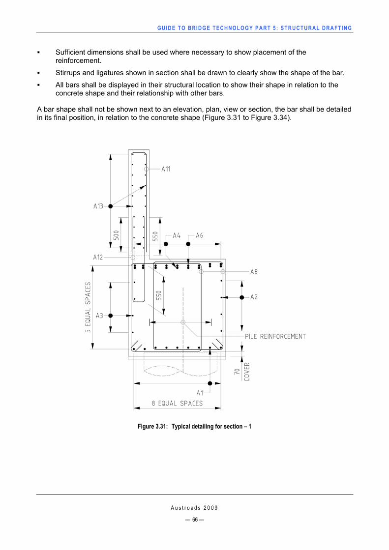
GUIDE TO BRIDGE TECHNO LOGY PART 5 : STRUCTURAL DRAFT ING
Sufficient dimensions shall be used where necessary to show placement of the reinforcement.
Stirrups and ligatures shown in section shall be drawn to clearly show the shape of the bar.
All bars shall be displayed in their structural location to show their shape in relation to the concrete shape and their relationship with other bars.
A bar shape shall not be shown next to an elevation, plan, view or section, the bar shall be detailed in its final position, in relation to the concrete shape (Figure 3.31 to Figure 3.34).
Figure 3.31: Typical detailing for section – 1
A u s t r o a d s 2 0 0 9
— 66 —
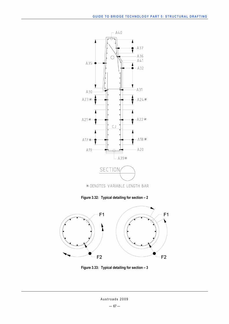
GUIDE TO BRIDGE TECHNO LOGY PART 5 : STRUCTURAL DRAFT ING
Figure 3.32: Typical detailing for section – 2
Figure 3.33: Typical detailing for section – 3
A u s t r o a d s 2 0 0 9
— 67 —
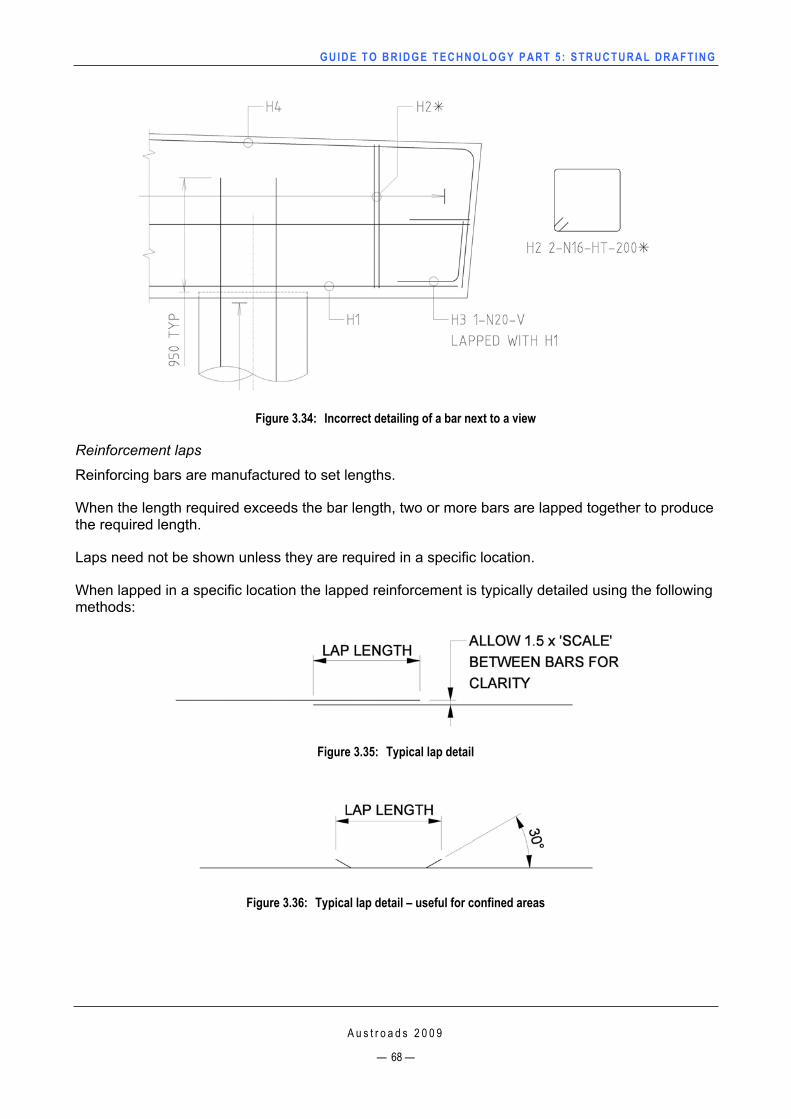
GUIDE TO BRIDGE TECHNO LOGY PART 5 : STRUCTURAL DRAFT ING
Figure 3.34: Incorrect detailing of a bar next to a view
Reinforcement laps
Reinforcing bars are manufactured to set lengths.
When the length required exceeds the bar length, two or more bars are lapped together to produce the required length.
Laps need not be shown unless they are required in a specific location.
When lapped in a specific location the lapped reinforcement is typically detailed using the following methods:
Figure 3.35: Typical lap detail
Figure 3.36: Typical lap detail – useful for confined areas
A u s t r o a d s 2 0 0 9
— 68 —
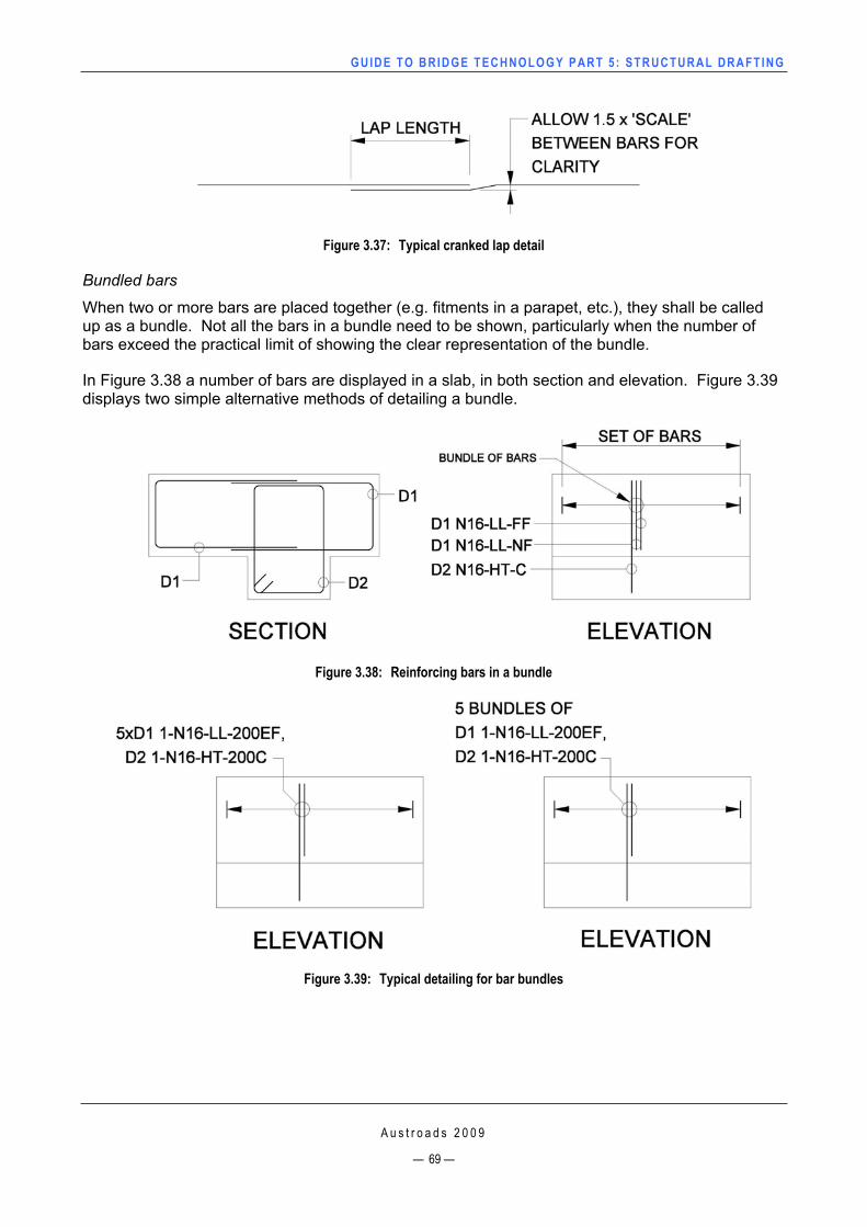
GUIDE TO BRIDGE TECHNO LOGY PART 5 : STRUCTURAL DRAFT ING
Figure 3.37: Typical cranked lap detail
Bundled bars
When two or more bars are placed together (e.g. fitments in a parapet, etc.), they shall be called up as a bundle. Not all the bars in a bundle need to be shown, particularly when the number of bars exceed the practical limit of showing the clear representation of the bundle.
In Figure 3.38 a number of bars are displayed in a slab, in both section and elevation. Figure 3.39displays two simple alternative methods of detailing a bundle.
Figure 3.38: Reinforcing bars in a bundle
Figure 3.39: Typical detailing for bar bundles
A u s t r o a d s 2 0 0 9
— 69 —
GUIDE TO BRIDGE TECHNO LOGY PART 5 : STRUCTURAL DRAFT ING
A u s t r o a d s 2 0 0 9
— 70 —
Cover to reinforcement
All reinforcement drawings shall contain a note giving the required cover from a concrete face to the reinforcement, e.g. ‘Nominal cover to reinforcement nearest to the concrete surface shall be 40 mm, unless specified otherwise.’
When the cover is not as stated, the cover must be detailed (Figure 3.31).
3.6 Structural Steel Detailing 3.6.1 GeneralStructural steelwork drawings shall show sufficient detail for the complete fabrication of a particular item or sufficient detail to enable the fabricator to prepare detailed shop drawings for the particular item.
For simple fabrication work, such as bridge girders that are made from rolled steel sections, universal beams and built-up plate girders, shop drawings are not usually prepared.
Each item of fabricated steelwork shall be detailed in the form with which the item would be released from the fabrication shop, with each and every part that would be attached in the fabrication shop, shown as part of the total assembly.
Fabricated items that form part of the total assembly need not be detailed as separate items, nor shall the quantity of those items be shown separately unless unduly complicated, and in such a case, the quantity of those items is shown and detailed separately.
In the majority of cases, it is sufficient to detail a fabricated item in one or two views, with enlarged details of the more complex portions as necessary.
Where items are to be bolted or welded together in the field, (e.g. where steel cross girders are to be attached to the main girders), an assembly drawing showing all components in their final position in the structure shall be provided.
3.6.2 Standard Items Standard items, such as bolts, nuts and screws need not be fully detailed. If items are not fully detailed, they shall be sufficiently described to enable correct identification.
Bolts, nuts and washers shall be described separately on drawings due to the different Australian Standards they refer to.
3.6.3 Non-standard Items All non-standard items shall be fully detailed with all relevant dimensions, thread length, thread type and surface finish indicated as appropriate.
3.6.4 Closing Dimensions In accordance with industry practice, overall dimensions of steel items shall be provided to enable correct manufacture.
GUIDE TO BRIDGE TECHNO LOGY PART 5 : STRUCTURAL DRAFT ING
A u s t r o a d s 2 0 0 9
— 71 —
3.6.5 Protective Treatment The required protective treatment shall be specified on the drawings and it shall be appropriate for the item under consideration, (e.g. for large items, it may be inappropriate to specify that the item be hot-dip galvanised after manufacture).
In all cases where protective treatment of steelwork is required, a note shall be included in the general notes on the drawing.
Where fabricated steel items have been hot-dip galvanised and the surface of the protective coating has been disturbed or damaged for any reason, a note shall be included in the general notes on the drawing for the treatment and repair of the damaged surface.
GUIDE TO BRIDGE TECHNO LOGY PART 5 : STRUCTURAL DRAFT ING
A u s t r o a d s 2 0 0 9
— 72 —
REFERENCESAustroads 2008, Glossary of Austroads terms, 2nd edn., by K Sharp & P Milne, AP-C87/08 Austroads,
Sydney, NSW.
Department of Planning and Infrastructure, Northern Territory 2007, CADD manual, version 1.3 , DPI, Darwin, NT.
Department for Transport, Energy and Infrastructure, South Australia 2008, ‘Structures group drafting guidelines’ version 2, DTEI, Adelaide, SA.
Main Roads Western Australia, 2009, Drafting guidelines and practices manual, MRWA, Perth, WA.
Roads and Traffic Authority, New South Wales 2007, Structural drafting and detailing manual, RTA, Sydney, NSW.
Queensland Department of Main Roads 2008, Bridge design drafting manual, QDMR, Brisbane, Qld.
VicRoads n.d, ‘A selection of bridge related project drawings’, VicRoads, Kew, Vic. (unpublished).
Standards Australia
AS 1100.101-1992, Technical drawing: general principles.
AS 1100.301-2008, Technical drawing: architectural drawing.
AS 1100.401-1984, Technical drawing: engineering survey and engineering survey design drawing.
AS/NZS 1100.501-2002, Technical drawing: structural engineering drawing.
AS ISO 1302-2005, Geometrical product specifications (GPS): indication of surface texture in technical product documentation.
AS 1348-2002, Glossary of terms: roads and traffic engineering.
AS/NZS 4671-2001, Steel reinforcing materials.
AS 5100.1-2004, Bridge design: scope and general principles.