Embed Size (px)
Citation preview

Title: Camera-based Triggering of Bridge Structural Health Monitoring Systemsusing a Cyber-Physical System Framework
Authors : Rui Hou1
Seongwoon Jeong2
Ying Wang1
Kincho H. Law2
Jerome P. Lynch1

ABSTRACT
A cyber-physical framework is proposed in this paper to integrate the measured re-sponse of two highway bridges and a weigh-in-motion system located along the samehighway corridor. Leveraging traffic images captured by existing traffic cameras, com-puter vision techniques such as histogram of oriented gradients are utilized to detecttrucks in images and synchronize measured vehicle-induced bridge data and truck weightswith images of vehicle loads. Those images then act as a cyber-based linkage connect-ing the bridge monitoring systems and a weigh-in-motion system. Such a data fusionstrategy makes it possible to establish a clear input-output model for each bridge systemand explore the correlation between the responses of different bridges to same trucks. Inaddition, the camera system can also be used to trigger bridge monitoring systems intel-ligently to measure more truck events with a limited monitoring system power supply.
INTRODUCTION
Innovative bridge health monitoring systems have been developed over the last decadeto facilitate data-driven approaches to bridge health management. Structural health mon-itoring (SHM) systems typically focus on a single bridge including measurement of itsenvironment and corresponding response to loads [1, 2]. However, the emergence of theInternet has driven new and exciting modes of connectivity between physical systems.In the United States highways are being transformed by this connectivity including theemergence of connected vehicles and intelligent transportation systems (ITS). The SHMof bridges can greatly benefit from these advances including integration of SHM datawith other ITS data such as camera feeds and direct quantification of vertical loadingimposed by heavy trucks [3]. This study explores the integration of three sources of datarelevant to bridge SHM: wireless sensor data collected from instrumented bridges, traf-fic cameras monitoring traffic flow, and data from weigh-in-motion (WIM) systems. The20-mile-long I-275 corridor between Monroe and Romulus, Michigan is established in
1Rui Hou, Ying Wang, Jerome P. Lynch, Department of Civil and Environmental Engineering, Universityof Michigan, Ann Arbor, MI 48105, USA.2Seongwwon Jeong, Kincho H. Law, Department of Civil and Environmental Engineering, Stanford Uni-versity, Stanford, CA 94305, USA.
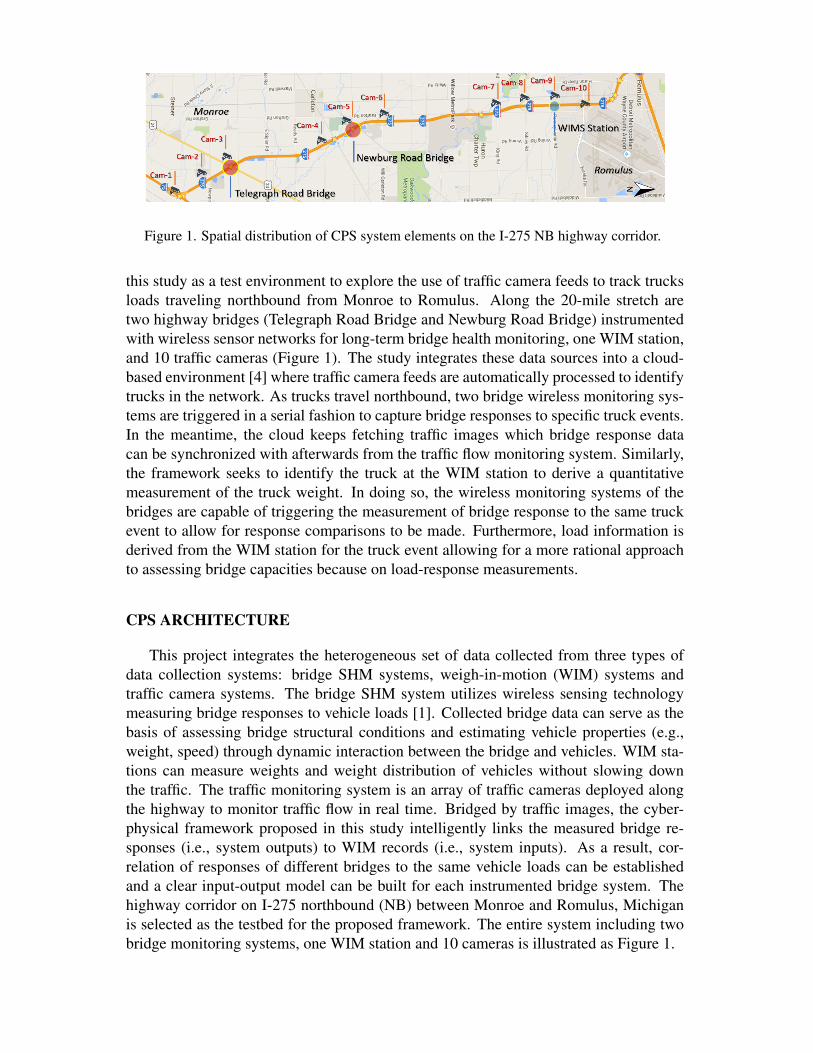
Figure 1. Spatial distribution of CPS system elements on the I-275 NB highway corridor.
this study as a test environment to explore the use of traffic camera feeds to track trucksloads traveling northbound from Monroe to Romulus. Along the 20-mile stretch aretwo highway bridges (Telegraph Road Bridge and Newburg Road Bridge) instrumentedwith wireless sensor networks for long-term bridge health monitoring, one WIM station,and 10 traffic cameras (Figure 1). The study integrates these data sources into a cloud-based environment [4] where traffic camera feeds are automatically processed to identifytrucks in the network. As trucks travel northbound, two bridge wireless monitoring sys-tems are triggered in a serial fashion to capture bridge responses to specific truck events.In the meantime, the cloud keeps fetching traffic images which bridge response datacan be synchronized with afterwards from the traffic flow monitoring system. Similarly,the framework seeks to identify the truck at the WIM station to derive a quantitativemeasurement of the truck weight. In doing so, the wireless monitoring systems of thebridges are capable of triggering the measurement of bridge response to the same truckevent to allow for response comparisons to be made. Furthermore, load information isderived from the WIM station for the truck event allowing for a more rational approachto assessing bridge capacities because on load-response measurements.
CPS ARCHITECTURE
This project integrates the heterogeneous set of data collected from three types ofdata collection systems: bridge SHM systems, weigh-in-motion (WIM) systems andtraffic camera systems. The bridge SHM system utilizes wireless sensing technologymeasuring bridge responses to vehicle loads [1]. Collected bridge data can serve as thebasis of assessing bridge structural conditions and estimating vehicle properties (e.g.,weight, speed) through dynamic interaction between the bridge and vehicles. WIM sta-tions can measure weights and weight distribution of vehicles without slowing downthe traffic. The traffic monitoring system is an array of traffic cameras deployed alongthe highway to monitor traffic flow in real time. Bridged by traffic images, the cyber-physical framework proposed in this study intelligently links the measured bridge re-sponses (i.e., system outputs) to WIM records (i.e., system inputs). As a result, cor-relation of responses of different bridges to the same vehicle loads can be establishedand a clear input-output model can be built for each instrumented bridge system. Thehighway corridor on I-275 northbound (NB) between Monroe and Romulus, Michiganis selected as the testbed for the proposed framework. The entire system including twobridge monitoring systems, one WIM station and 10 cameras is illustrated as Figure 1.

Figure 2. Telegraph Road Bridge (left) and Newburg Road Bridge (right).
Bridge Health Monitoring System
Along the corridor, two instrumented highway bridges, the Telegraph Road Bridge(TRB) and the Newburg Road Bridge (NRB), are both built in 1973 and owned by theMichigan Department of Transportation (MDOT). Shown in Figure 2 left is the TRBwhich is a multi-girder composite steel bridge located in Monroe. It spans 224 feet(68.28 m) in total including a main span of 128 feet (39.01 m) and two wing spans each48 feet (14.63 m). The main span is connected to the cantilever ends of the two wingspans through pin-hanger assemblies while the wing spans are supported by concretepiers. Carrying three lanes of I-275 NB, the TRB consists of seven girder lines under-neath a steel reinforced concrete deck. The NRB, also presented in Figure 2, is a singlespan bridge with a length of 105 feet (32.00 m) located 4.5 miles downstream (north)of the TRB. It also carries three lanes using seven steel plate girders and a compositereinforced deck.
The two bridges are both instrumented with the long-term automated wireless sensornetwork (WSN) to measure bridge responses to passing vehicles. A WSN is composedof a number of Narada [5] sensing nodes and a base station. In a sensing node, thesensors, strain gages or accelerometers, are interfaced with the Narada wireless sensingunit through conditioning circuits (e.g., low-pass filters) and a 16-bit ADC. Each nodeis powered by a 12V 3.2Ah sealed lead acid (SLA) battery which is charged by a 12Wsolar panel. The base station of each bridge is used to send operational commands tothe wireless sensing nodes (e.g., sleep), collect sensor measurements from nodes andforward data to a cloud database [4]. Their primary components are one single boardcomputer (Winsystems PPM-LX800-G) which is connected to Internet over LTE andone CC2420 RF transceiver connected to an external high-gain omni-directional antenna.The base stations are powered by 12V 40Ah SLA batteries with 160W solar panels.
This study applies Hitec HBWF-35-125-6-10GP-TR weldable strain gages, BDIST350 strain transducers, and Silicon Design 2012-002 uniaxial accelerometers for themeasurements of steel girder strain responses, concrete slab strain responses and accel-eration responses, respectively. Weldable strain gages are welded to the web-bottom ofgirders to measure the longitudinal bending strain caused by vehicle loads. BDI gagesare bolted to the bottom surface of the bridge slab to measure the local tensile straincaused by direct wheel loads, which is commonly used as an axle detector in bridgeweigh-in-motion (BWIM) technology [6]. Accelerometers are mounted to the bottomflange of girders to measure vehicle-induced vibrations in the bridge. Based on the mea-sured acceleration, the TRB and NRB exhibit a first modal frequency of 2.4Hz and 4.2Hz, respectively. Accordingly, the sampling rate is set to be 100 Hz for strain gages and200 Hz for accelerometers. In addition, a few thermistors (LM35DT) are also installed

Figure 3. Sensor layout on TRB (top) and NRB (bottom) with sensor types defined.
to measure the ambient temperature of the bridge. The TRB system was installed in2011 while the NRB system was newly installed in 2016. Their current sensor layout isshown in Figure 3.
Weigh-in-Motion System
Highway weigh-in-motion (WIM) stations play a vital role in highway traffic mon-itoring systems. WIM stations, with sensors installed within the road pavement, arecapable of continuously estimating the gross weight (i.e., static weight) of a vehicle aswell as the load distribution of weight carried by each axle or axle group on the vehi-cle. In addition to weight, vehicle signatures such as the number of axles, axle spacingand speed are also recorded. Compared to traditional scale stations, the WIM station ismore cost efficient because it obtains measurements without slowing down the highwaytraffic. Relying on truck weight information collected, governments can conduct truckweight limit enforcement more efficiently. The WIM station underneath the Pennsylva-nia Road Bridge at the north end of I-275 in Romulus is used in this study for providinginformation of truck weight. It is the only WIM station on this segment of I-275. Onecaveat though is the presence of 4 exits which allow trucks to enter and exit the highway.This fact further justifies the need for camera and computer vision to track trucks.
Traffic Monitoring System
The traffic monitoring system is a traffic video network managed by MDOT. Allimages captured by the traffic cameras are available to the team in real time. There are10 cameras located in the range of the corridor as labelled in Figure 1. The networkupdates images at each location every 2 seconds but sometimes the update interval canincrease to 10 seconds due to network latency. Each image has a resolution of 352x240
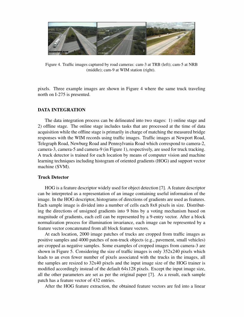
Figure 4. Traffic images captured by road cameras: cam-3 at TRB (left); cam-5 at NRB(middle); cam-9 at WIM station (right).
pixels. Three example images are shown in Figure 4 where the same truck travelingnorth on I-275 is presented.
DATA INTEGRATION
The data integration process can be delineated into two stages: 1) online stage and2) offline stage. The online stage includes tasks that are processed at the time of dataacquisition while the offline stage is primarily in charge of matching the measured bridgeresponses with the WIM records using traffic images. Traffic images at Newport Road,Telegraph Road, Newburg Road and Pennsylvania Road which correspond to camera-2,camera-3, camera-5 and camera-9 (in Figure 1), respectively, are used for truck tracking.A truck detector is trained for each location by means of computer vision and machinelearning techniques including histogram of oriented gradients (HOG) and support vectormachine (SVM).
Truck Detector
HOG is a feature descriptor widely used for object detection [7]. A feature descriptorcan be interpreted as a representation of an image containing useful information of theimage. In the HOG descriptor, histograms of directions of gradients are used as features.Each sample image is divided into a number of cells each 8x8 pixels in size. Distribut-ing the directions of unsigned gradients into 9 bins by a voting mechanism based onmagnitude of gradients, each cell can be represented by a 9-entry vector. After a blocknormalization process for illumination invariance, each image can be represented by afeature vector concatenated from all block feature vectors.
At each location, 2000 image patches of trucks are cropped from traffic images aspositive samples and 4000 patches of non-truck objects (e.g., pavement, small vehicles)are cropped as negative samples. Some examples of cropped images from camera-3 areshown in Figure 5. Considering the size of traffic images is only 352x240 pixels whichleads to an even fewer number of pixels associated with the trucks in the images, allthe samples are resized to 32x40 pixels and the input image size of the HOG trainer ismodified accordingly instead of the default 64x128 pixels. Except the input image size,all the other parameters are set as per the original paper [7]. As a result, each samplepatch has a feature vector of 432 entries.
After the HOG feature extraction, the obtained feature vectors are fed into a linear

Figure 5. Positive samples (top) and negative samples (bottom) from traffic cameras.
Figure 6. Detection results on images of cam-3 at TRB.
support vector machine [8] for training in order to learn an SVM truck detector. Thisprocedure is realized through a package called SVM-light [9]. The detection task is thenimplemented using the OpenCV library [10] in Python. During the detection, severalsliding windows with different scales are scanning through an image to determine if atruck appears in any position. As can be seen in Figure 5, within images of a certaincamera, most trucks have a very similar graphic pattern in that they all have a contourwith a near diamond shape in the cropped patches, which makes it easier for the linearSVM classifier to accurately detect trucks. The resulting classifier owns a precision of95% and a recall of 78%. Some qualitative detection results on images of cam-3 arepresented in Figure 6.
Online Data Integration Stage
Online data integration involves triggering the bridge monitoring systems and syn-chronizing measured bridge responses with traffic images. A computation node de-ployed on Windows Azure cloud service is used to facilitate the fusion process. Shownin Figure 7, the cloud keeps fetching images from cam-2 and conducting truck detec-tion in real-time. Once a truck is detected at the location of cam-2, the cloud will sendwake-up messages to the TRB and the NRB monitoring systems in a consecutive fashionto activate the data acquisition (DAQ) processes on a schedule based on their distances(which dictates travel times) to cam-2. In the meantime, the cloud starts to crawl photosfrom cam-3, cam-5 and cam-9 accordingly and stores them into a NoSQL database [4].After the DAQ process on the TRB and the NRB, the base stations at each bridge willupload collected data to the cloud. A strain peak detection script will then run on thecollected bridge response data to detect dominant strain peaks that are larger than athreshold (e.g., 15 micro-strain). Those strain peaks are assumed to correspond to heavyloads (i.e., trucks) running over the two bridges. Based on the time stamps of thosestrain peaks, traffic images are queried from the database and matched with the bridgeresponses.
Offline Data Integration Stage

Figure 7. Online stage of data fusion process.
Figure 8. Correlation between vehicle weights and bridge strain responses (left); comparison ofbridge strain responses of two bridges (right).
Offline data integration refers to the process of matching trucks detected at the twobridges and the WIM station based on traffic images. To the best of the authors’ knowl-edge, because of the low resolution, no existing computer vision algorithm can extract asufficient number of repeatable and distinct features from a truck image patch to robustlyrecognize matches in other images. Consequently, this matching process is conductedmanually without the use of computer vision techniques. This task is even challengingto human operators. An example of matched traffic images is shown in Figure 4 wherethe logo printed on the side of the truck is the key visual feature used for matching.
The correlation between the maximum truck-induced bridge strain response and thegross weight of corresponding truck is plotted in Figure 8 for the TRB (sensor S8) andthe NRB (sensor S2); as expected, there exists a positive correlation between them. Inaddition, presented in Figure 8 is a comparison between strain responses measured atboth bridges using data from the same pair of sensors. Measured data points are scatteredaround the theoretical relationship obtained from finite element model simulation usingthe truck weight. In the plot, lane 1 refers to the slow lane while lane 3 refers to the fast(passing) lane, as shown in Figure 3.
CONCLUSION
This study proposed and implemented a cyber-physical system (CPS) framework tolink multiple bridge monitoring systems with a nearby weigh-in-motion station takingadvantage of computer vision techniques to identify truck events. This approach to data

fusion makes it possible to match measured bridge responses to corresponding inputloads. The platform can serve as a testbed for bridge load rating, BWIM algorithm vali-dation and other applications that are difficult to conduct without load information. Sincethe low resolution of traffic images constrains the level of automation that can be attainedin the current framework and the accuracy of truck detection/matching, some ongoingwork is focused on improving the performance of the system by replacing current trafficcameras with high-resolution cameras, training deep learning models for faster and moreaccurate truck detection and developing automated truck matching program.
ACKNOWLEDGEMENT
The research is supported by a collaborative project funded by the US National Sci-ence Foundation (Grant No.EECS-1446330 to Stanford University and Grant No.EECS-1446521 to the University of Michigan). This research is also partially supported byGrant No.13SCIPA01 from the Smart Civil Infrastructure Research Program funded byMOLIT of Korea government and KAIA. The authors thank the Michigan Department ofTransportation (MDOT) for access to the Telegraph Road Bridge and the Newburg RoadBridge and for offering support during installation of the wireless monitoring system.
REFERENCES1. OConnor, S. M., Y. Zhang, J. P. Lynch, M. M. Ettouney, and P. O. Jansson. 2017. “Long-term
performance assessment of the Telegraph Road Bridge using a permanent wireless monitor-ing system and automated statistical process control analytics,” Structure and InfrastructureEngineering, 13(5):604–624, doi:10.1080/15732479.2016.1171883.
2. Ko, J. and Y. Ni. 2005. “Technology developments in structural health monitoring of large-scale bridges,” Engineering structures, 27(12):1715–1725.
3. Khan, S. M., S. Atamturktur, M. Chowdhury, and M. Rahman. 2016. “Integration of struc-tural health monitoring and intelligent transportation systems for bridge condition assess-ment: current status and future direction,” IEEE Transactions on Intelligent TransportationSystems, 17(8):2107–2122.
4. Jeong, S., R. Hou, J. P. Lynch, H. Sohn, and K. H. Law. 2017. “An information modelingframework for bridge monitoring,” Advances in Engineering Software.
5. Hou, R., Y. Zhang, S. OConnor, Y. Hong, and J. Lynch. 2015. “Monitoring and Identificationof Vehicle-Bridge Interaction using Mobile Truck-based Wireless Sensors,” in Proceedingsof 11th International Workshop on Advanced Smart Materials and Smart Structures Tech-nology, pp. 1–2.
6. Lydon, M., S. Taylor, D. Robinson, A. Mufti, and E. Brien. 2016. “Recent developments inbridge weigh in motion (B-WIM),” Journal of Civil Structural Health Monitoring, 6(1):69–81.
7. Dalal, N. and B. Triggs. 2005. “Histograms of oriented gradients for human detection,”in Computer Vision and Pattern Recognition, 2005. CVPR 2005. IEEE Computer SocietyConference on, IEEE, vol. 1, pp. 886–893.
8. Vapnik, V. 2013. The nature of statistical learning theory, Springer science & business me-dia.
9. Joachims, T. 1999. “Making large-Scale SVM Learning Practical,” in B. Scholkopf,C. Burges, and A. Smola, eds., Advances in Kernel Methods - Support Vector Learning,MIT Press, Cambridge, MA, chap. 11, pp. 169–184.
10. Bradski, G. Dr. Dobb’s Journal of Software Tools.

CONTRIBUTING AUTHOR COPYRIGHT RELEASE FORM
As author of the chapter/contribution titled Camera-based Triggering of Bridge
Structural Health Monitoring Systems using a Cyber-Physical System Framework,
to appear in the Proceedings of Structural Health Monitoring 2017, I hereby agree
to the following:
1. To grant to DEStech Publications, Inc., 439 North Duke Street, Lancaster,
PA, 17602, copyright of the above named chapter/contribution (for U.S.
Government employees to the extent transferable), in print, electronic, and online
formats. However, the undersigned reserve the following:
a. All proprietary rights other than copyright, such as patent rights.
b. The right to use all or part of this article in future works.
DEStech Publications thereby retains full and exclusive right to publish, market,
and sell this material in any and all editions, in the English language or otherwise.
1 I warrant to DEStech Publications, Inc., that I am the (an) author of the
above-named chapter/contribution and that I am the (a) copyright holder of the
above-named chapter/contribution granted to DEStech Publications, Inc.
2 I warrant that, where necessary and required, I have obtained written
permission for the use of any and all copyrighted materials used in the above-
named chapter/contribution. I understand that I am responsible for all costs of
gaining written permission for use of copyrighted materials.
3 I agree to assume full liability to DEStech Publications, Inc. and its licensee,
and to hold DEStech Publications, Inc. harmless for any claim or suit filed against
DEStech Publications, Inc. for violation of copyrighted material used in the above-
named contribution.
Please sign and date this form and retain a copy for your records. Please include
original form with your chapter/paper.
Thank you for your cooperation.
Please print name: __________ Signed: ___________ Dated: ____________
439 NORTH DUKE STREET • LANCASTER, PENNSYLVANIA 17602-4967, U.S.A. Toll Free:
(866) 401-4337 • Tel: (717) 290-1660 • Fax: (717) 509-6100 E-mail: [email protected] •
Internet address: www.destechpub.com