Embed Size (px)
Citation preview
Transmutation Research Program Reports (TRP) The Nuclear Science and Technology Division:Transmutation Research Program (TRP)
9-30-2005
AFCI Quarterly Input: UNLV July 1 throughSeptember 30, 2005Harry Reid Center for Environmental Studies. Nuclear Science and Technology Division
Follow this and additional works at: https://digitalscholarship.unlv.edu/hrc_trp_reports
Part of the Nuclear Commons, Nuclear Engineering Commons, and the RadiochemistryCommons
This Report is brought to you for free and open access by the The Nuclear Science and Technology Division: Transmutation Research Program (TRP)at Digital Scholarship@UNLV. It has been accepted for inclusion in Transmutation Research Program Reports (TRP) by an authorized administratorof Digital Scholarship@UNLV. For more information, please contact [email protected].
Repository CitationHarry Reid Center for Environmental Studies. Nuclear Science and Technology Division (2005). AFCI Quarterly Input: UNLV July 1through September 30, 2005.Available at: https://digitalscholarship.unlv.edu/hrc_trp_reports/17
1
AFCI Quarterly Input – UNLV July 1 through September 30, 2005 1.0 University of Nevada, Las Vegas (UNLV) UNLV Transmutation Research Program. The University of Nevada, Las Vegas supports the AFCI through research and development of technologies for economic and environmentally sound refinement of spent nuclear fuel. The UNLV program has four components: infrastructure, international collaboration, student-based research, and management and program support. Management and program support highlights are the following:
• Eight second year renewal proposals for projects starting Fall term 2004 were submitted and approved. Limited funds prevent proposals for new projects to be entertained at this time.
• Jinsuo Zhang, LANL, gave a seminar entitled “Lead Bismuth Eutectic Research” on July 7.
• Anthony Hechanova and Thomas Ward visited the University of Nevada, Reno on July 15 and met with administrators and faculty in the Chemical and Metallurgical Engineering Department and Civil and Environmental Engineering Department to discuss their AFCI earmarks.
• The UNLV local television station interviewed faculty and students regarding the transmutation research program on July 22. They will provide a transcript for review before the final cut is made and aired.
• The World Nuclear University Summer Institute session on Nevada nuclear politics, perception, and UNLV nuclear programs was held in Las Vegas, NV on Aug. 19.
• Gary Cerefice and Anthony Hechanova participated in the Deep Burn progress and FY06 planning meeting in Salt Lake City, UT, on Aug. 30. Consensus was reached on recommendations for FY06 that will be presented to Buzz Savage on Sept. 20.
• Twenty posters from UNLV TRP tasks were submitted and posted at the AFCI Semi-annual Review in Crystal City, VA. The TRP annual report for the academic year 2004-2005 was also distributed at the meeting.
• Susan Eisenhower (granddaughter of President Dwight D. Eisenhower) gave a seminar at UNLV on Sept. 23 entitled “Nuclear Energy, International Cooperation, and Leadership.”
1.1 Infrastructure Augmentation 1.1.1 Infrastructure Augmentation Scope The infrastructure augmentation component of the UNLV Transmutation Research Program enhances UNLV’s research staff, facilities, and academic programs to increase the ability of the university to perform AFCI research. 1.1.2 Infrastructure Augmentation Highlights
• Facilities Progress Update. The ISTC TC-1 target loop was successfully installed and all systems are operational. The TEM User laboratory will hold its grand opening to the
2
UNLV campus on Oct. 7 and will be promoted as a stand-alone, self-supporting user facility.
• Al Sattelberger, a Senior Laboratory Fellow at Los Alamos National Laboratory, joined the UNLV Radiochemistry Program on Sept. 1. His office and laboratories are located in the Harry Reid Center and his activities will support the TRP research efforts with particular emphasis on synthetic, mechanistic, and structural technetium and uranium chemistry. He will also teach a course in advanced inorganic chemistry.
1.2 International Collaboration 1.2.1 International Collaboration Scope The international collaboration component of the UNLV Transmutation Research Program enhances UNLV’s breadth of scientific and scholastic experience. University collaboration is also an efficient conduit for international collaboration that benefits the national AFCI program. Six Russian visiting scientists from the Institute for Physics and Power Engineering (IPPE, Obninsk, Russia) assisted in the final installation of the ISTC TC-1 Loop from Sept. 9 to 23. The loop was successfully installed and all systems were operational. Ning Li will help develop the path forward with the use of the TC-1 (potentially to support MEGAPIE) and the revision of scope of work to finish out the IPPE contract through the end of calendar year 2005. UNLV also has ongoing relationships with the Ben Gurion University of the Negev in Beer Sheva, Israel (Task 19). 1.3 Student Research 1.3.1 Student Research Scope The Student Research component is the core of the UNLV Transmutation Research Program. The milestones, schedules, and deliverables of the student research projects are detailed in the individual research proposals. UNLV has 16 active student research tasks and 14 tasks that have concluded. The tasks are divided below in terms of their research area: fuels, separations, and transmutation sciences. 1.3.2 Student Research Highlights FUELS TECHNOLOGY Metallic Fuel Pins (Task 1) Highlights.
• Project completed in June 2004. Theses generated: Xiaolong Wu, M.S., Mechanical Engineering, “Design and Analysis for Melt Casting Metallic
Fuel Pins Incorporating Volatile Actinides,” August 2002. Taide Tan, M.S., Mechanical Engineering, “Design and Simulation of an Induction Skull
Melting System,” May 2004. Remote Fuel Fabrication (Task 9) Highlights.
• Project completed in August 2004. See Task 22 for follow-on project. Thesis generated:

3
Jae-Kyu Lee, Ph.D., Department of Mechanical Engineering, “Three Dimensional Pattern Recognition using Feature-based Indexing and Rule-based Search,” December 2003.
Interaction between Metal Fission Products and TRISO Coating Materials (Task 17) Highlights.
• Fixed a variety of unrelated technical problems in the surface analysis and modification instrument.
• Installed Inverse Photoemission detector and electron gun, and completed manufacture of electronics for Inverse Photoemission detector.
• Began next experimental campaign on the Pd/SiC interface • Conducted further analysis of data taken at the Advanced Light Source, planning for next
beamtime in Nov. 2005. Dissolution, Reactor, and Environmental Behavior of ZrO2-MgO Inert Fuel Matrix (Task 19) Highlights.
• The synthesis of Zr-Mg matrix containing cerium and erbium is ongoing and the method has been finalized and approved for the incorporation of uranium into the ceramics.
• A method is being developed to study the dissolution of the material in high temperature, high pressure water; simulating reactor conditions. A soxhlet has been set up to study the dissolution of the material in elevated temperature and moisture conditions.
• Examining the solubility of the ceramic in reprocessing conditions is now underway. A method is also being developed to analyze samples by x-ray fluorescence.
• Neutronic calculations using three-dimensional simulations of two reference cores were performed. The results of 3D calculations of reference cores will provide the basis for the consistent comparison of the future FFF cores designs.
Design Concepts and Process Analysis for Transmuter Fuel Manufacturing (Task 22) Highlights.
• A Hot Cell robotic assembly: Pick and place dynamic simulation, including feedback control with Matlab, for dispersion Fuel manufacture was developed further. An analysis of multiple possible plant configurations was begun inside the hot cell with regard to their effects on reliability, fuel throughput, and operating costs.
• Mechanical Engineering student Andreas J. Roderburg joined the project in August. Andreas is visiting form the RWTH Aachen in Germany, and is working on his Diploma thesis.
Impact of the Synthesis Process on Structure Properties for AFCI Fuel Candidates (Task 28) Highlights
• Sample preparation equipment (ultrasonic disk cutter and Allied multi-preparation system) was tested on surrogate fuel samples and students have been trained.
• Intense literature research was conducted on wet-chemical fuel processing using sol-gel methods. Literature on the wet-chemical sol-gel synthesis of nuclear fuels in the systems U-Th-REE-O was obtained and evaluated.
• Laboratory-scale sol-gel fuel synthesis, glassware, instrumentation, and chemicals have been ordered for the experimental set-up on wet-chemical fuel synthesis using sol-gel technique.
4
• Optimization of the dry-chemical route on the synthesis of oxide and nitride fuels was investigated by adjusting particle size and sinter temperature.
• Phase pure fertile fuel solid solution samples were used as precursors for nitride fuel synthesis in the system ZrN-ErN-UN.
• Thermal analysis studies were conducted on non-fertile nitride fuels to understand mass gain and endothermic reaction of nitride fuel above 1100°C.
• Synthesis of fertile fuel samples in the system ZrO2-ErO1.5-UO2 by dry chemical processing and synthesis of nitride fuel by applying carbothermic reduction / nitrification process were conducted, but oxide impurities were determined.
• Samples in the oxide systems ZrO2-ErO1.5-UO2 and the nitride system ZrN-ErN-UN were prepared for light microscopy and scanning electron microscopy.
• Samples in the nitride system ZrN-ErN-UN were prepared for transmission electron microscopy (TEM).
SEPARATIONS TECHNOLOGY Systems Engineering Model (Task 8) Highlights.
• Project completed in August 2004. See Task 24 for follow-on project. Thesis generated: Lijian Sun, M.S., Mechanical Engineering, “Development of a Systems Engineering Model for
Chemical Separation Process,” December 2003. Nuclear Criticality Analyses for Transmuter Fuel Fabrication and Reprocessing (Task 11) Highlights.
• Project completed in December 2004. Thesis generated: Elizabeth Bakker, M.S., Mechanical Engineering Department, “Criticality and Thermal Analysis
of Separated Actinides in Transmutation,” November 2003. Immobilization of Fission Iodine (Task 15) Highlights.
• Established a new method for measuring IOH in the presence of iodate. • Elucidated the mechanism of interaction between iodate and NOM. • Established the occurrence of IOH as an intermediate in the reduction process. • Established a 1:1 reaction order for the reaction of hydroquinone with iodate.
Fluorapatite Waste Forms (Task 16) Highlights.
• Projects were completed. Theses and publications on the research conducted will be prepared and submitted.
Development of Integrated Process Simulation System Model for Spent Fuel Treatment Facility Design (Task 24) Highlights.
• The implemented reporting/analysis features of the TRPSEM package from the previous quarter were further refined to document more details of flowsheet simulation into the database, to display simulation progress, to validate information completeness with color coded boxes and to create prototype interface connecting to ASPEN-plus.
• Simplified separation flowsheets were constructed using ASPEN-plus using chemical separation information provided by ANL.
5
Electrochemical Separation of Curium and Americium (Task 25) Highlights. • The complexation of Ce with ligands including citrate, EDTA and NTA were initiated to
expand the pH range accessible for examining the Ce3+/Ce4+ redox couple. • Completed the initial measurements with citrate and EDTA ligands. • Initiated the polymer studies for the electrochemical separations. Attempted the
electrochemical growth of polyaniline wires from an electrode surface. SEM will be used to examine the structure.
• Initiated the purchase of an additional electrochemical workstation to support second graduate student on the project.
Fundamental Chemistry of U and Pu in the TBP-Dodecane-Nitric Acid System (Task 26) Highlights.
• The uranyl-TBP system was evaluated by UV-Visible spectroscopy and HPLC. • Methods for the determination of uranium concentration by liquid scintillation counting
were investigated in detail. • The speciation behavior of Acetohydroxamic Acid (AHA) was investigated using UV-
VIS Spectroscopy. Standards containing AHA and Uranium were analyzed on the UV-VIS Spectrophotometer at 370 nm and 483 nm. The concentration of AHA in the samples was varied while the uranium concentration was held constant.
Investigation of Optical Spectroscopy Techniques for On-Line Materials Accountability in the Solvent Extraction Process (Task 29) Highlights.
• Project initiated September 1, 2005. • ANSI-based laser safety program for laser spectroscopy laboratory was developed. • Investigation of uranium detection in aqueous systems was begun.
Combined Radiation Detection Methods for Assay of Higher Actinides in Separation Processes (Task 30) Highlights
• The PI attended a kick-off meeting with DOE, LANL, INL, ANL, PNL, ISU, and others. • Modeling of the NMDS for monitoring Pu and Np in a separations processing pipe for
material control and accountability, continued. Effects of isotopic concentration were investigated.
• Germanium detector modeling with MCNPX was initiated based on a report from Sandia National Laboratories.
• A He-3 neutron multiplicity detector system was configured to measure actinides (Pu & Np, Pu & Am, or mixed TRU) in a processing pipe.
• Detailed UREX+ flowsheet information (concentrations, etc.) and solvent constituents for inclusion in MCNP modeling were obtained from ANL.
TRANSMUTATION SCIENCES Niobium Cavity Fabrication Optimization (Task 2) Highlights.
• Project completed in August 2005. Theses generated: Qin Xue, M.S., Mechanical Engineering, “Modeling and Simulation of the Chemical Etching
Process in Niobium Cavities,” August 2002.
6
Sathish K. Subramanian, M.S., Mechanical Engineering, “Modeling, Optimization, and Flow Visualization of Chemical Etching Process in Niobium Cavities,” December 2003.
Anoop George, M.S., Electrical and Computer Engineering Department, “Study of Secondary Electron Emission From Niobium at Cryogenic Temperatures,” August 2005.
LBE Corrosion of Steel (Task 3) Highlights.
• Project completed in May 2004. See Task 18 for follow-on project. Thesis generated: Daniel Koury, M.S., Physics Department, “Investigation of the Corrosion of Steel by Lead-
bismuth Eutectic (LBE) Using Scanning Electron Microscopy And X-ray Photoelectron Spectroscopy,” December 2002.
Environment-Induced Degradation and Crack-Growth Studies in Candidate Target Materials (Task 4) Highlights.
• Project completed in December 2004. Theses generated: Ramprashad Prabhakaran, M.S., Mechanical Engineering, “Environment-Induced Degradations
in a Target Structural Material for Transmutation Applications,” August 2004. Sudheer Sama, M.S., Mechanical Engineering, “Embrittlement and Localized Corrosion in Alloy
HT-9,” August 2004. Phani P. Gudipati, M.S., Mechanical Engineering, “Stress Corrosion Cracking Resistance of
Martensitic Stainless Steels for Transmutation Applications,” December 2004. Mohammad K. Hossain, Ph.D., Mechanical Engineering, “Stress Corrosion Cracking and
Hydrogen Embrittlement of Martensitic Alloy EP-825,” December 2004. Venkataramakrishnan Selvaraj, M.S., Mechanical Engineering, “Environment Assisted Cracking
of Target Structural Materials Under Different Loading Conditions,” December 2004. Modeling Corrosion in Oxygen-Controlled LBE Systems with Coupling of Chemical Kinetics and Hydrogen Transport (Task 5) Highlights.
• Project completed in August 2004. Theses generated: Chao Wu, M.S., Mechanical Engineering, “Study of Geometry Effects on Local Corrosion Rates
for LBE Loop,” July 2003. Kanthi K. Dasika, M.S., Mechanical Engineering, “Modeling Corrosion in Oxygen-Controlled
LBE Systems with Coupling of Chemical Kinetics and Hydrogen Transport,” November 2003.
Narain Armbya, M.S., Mechanical Engineering, “CFD Analysis of 3-D Thermalhydraulics Flow Effects on Wall Concentration Gradient Profiles for LBE Loop Fittings,” December 2004.
Neutron Multiplicity Measurements of Target/Blanket Materials (Task 6) Highlights.
• A data acquisition system (DAQS) incorporating a multi-component digital input/output board and Labview software was tested using simulated random input signals. Software was developed and tested.
• Sixteen detectors and all input connections with detectors were tested (two failed). • Programming of the data acquisition system for all 64 detectors was completed. • The NMDS was modeled as a fissile material detection system surrounding a process
pipe. Pu, Np, and Am isotopes were studied with spontaneous fission sources in MCNPX.
7
• A new high-speed computer was ordered to host the data acquisition board and LabView software to support higher count-rate experiments.
Development of Dose Conversion Coefficients for Radionuclides Produced in Spallation Neutron Sources (Task 7) Highlights.
• Project completed in August 2005. Theses generated: John P. Shanahan, M.S., Health Physics, “Dose Coefficients for Radionuclides Produced in a
Spallation Neutron Source,” August 2003. Yayun Song, M.S., Health Physics, “Investigation and Calculations of Dose Coefficients for
Radionuclides Produced in a Spallation Neutron Source Using the ENSDF and NUBASE Nuclear Databases,” May 2004.
Development of a Mechanistic Understanding of High-Temp Deformation of Alloy EP-823 for Transmutation Applications (Task 10) Highlights.
• Project completed in August 2004. Theses generated: Srinivasa R. Kukatla, M.S., “Corrosion and High-Temperature Deformation Characteristics of a
Target Structural Material for Transmutation Applications,” June 2004. Venkata Nagarjuna Potluri, M.S., “Effect of Heat Treatment on Deformation and Corrosion
Behavior of Type 422 Stainless Steel,” August 2004. Bhagath Yarlagadda, M.S., “Elevated Temperature Mechanical Properties and Corrosion
Characteristics Evaluation of Alloy HT-9,” August 2004. Radiation Transport Modeling using Parallel Computational Techniques (Task 12) Highlights.
• Project completed in December 2004. Thesis generated: Suresh B. Sadineni, M.S., Mechanical Engineering, “Benchmarking Photoneutron Production of
MCNPX Simulations with Experimental Results,” December 2002. Developing a Sensing System for the Measurement of Oxygen Concentrations in Liquid LBE Systems (Task 13) Highlights.
• Project completed in August 2005. Thesis generated: Ramkumar Sivaraman, M.S., Electrical and Computer Engineering, “Calibration of YSZ Sensor
for the Measurement of Oxygen Concentration in Liquid PBE,” December 2003. Use of Positron Annihilation Spectroscopy for Stress-Strain Measurements (Task 14) Highlights.
• Analyses of defects (dislocations) in martensitic Alloy EP-823, cold-reduced to different levels, have been completed using transmission electron microscopy. The resultant data has been accepted for publication in Material Science and Engineering A Journal (Elsevier Science) during this year.
• PAS measurements have been performed on tensile, welded and cold-worked specimens of Alloys EP-823 and HT-9 at the Idaho Accelerator Center of ISU.
• Neutron diffraction (ND) measurements were performed at the Atomic Energy of Canada Limited (AECL), Chalk River Laboratory using cold-worked and welded specimens of Alloy EP-823 and Alloy HT-9.
8
• TEM studies involving welded specimens of Type 304L stainless steel and Alloy EP-823 are being performed to characterize defects at the fusion line, heat-affected-zone and base metal.
Corrosion Mechanisms and Kinetics of Steels in Lead-Bismuth Eutectic (Task 18) Highlights.
• Start of operations in the High Temperature Materials Experiments Facility – full operations waiting on HVAC and power renovation.
• Work on initiation of second stage corrosion in 316 stainless exposed to LBE completed. • Significant experimental studies of steel exposed to LBE at DELTA loop were conducted
with LANL staff. Impact of Silicon on Corrosion Resistance of Stainless Steels in LBE Systems (Task 20) Highlights.
• Tensile properties of T91 grade steel with 1 and 2 weight percent (wt%) Si content have been evaluated at temperatures ranging between ambient and 550oC. Fractographic evaluations of the primary fracture surfaces of the cylindrical specimens by scanning electron microscopy have also been performed.
• The cracking susceptibility of T91 grade steel with 1 and 2 wt% Si content has been determined in an acidic solution at ambient and elevated temperatures under both constant-load and slow-strain-rate (SSR) conditions.
• Localized corrosion studies to determine the critical potentials of both heats (1 and 2 wt% Si) by cyclic potentiodynamic polarization method have been completed. Microstructural evaluations by optical microscopy have also been performed.
• Charpy impact testing and self-loaded double-cantilever-beam (DCB) specimens are being machined for evaluations of impact toughness and crack-growth, respectively.
Oxide Film Growth Modeling in LBE Systems (Task 21) Highlights.
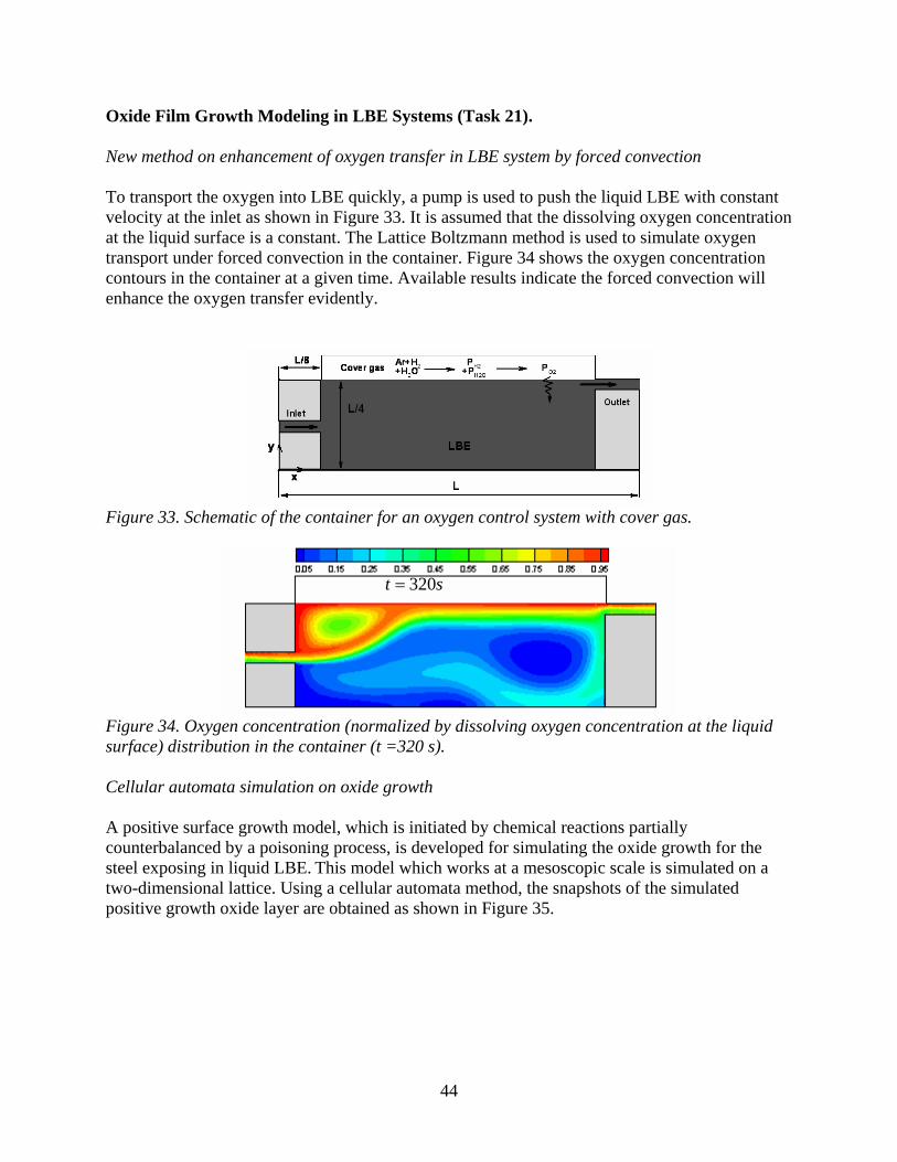
• A new method of using forced convection to enhance oxygen transfer in liquid metals under cover gas scheme was proposed and examined numerically.
• The positive surface growth model, which is initiated by chemical reactions partially counterbalanced by a poisoning process, was developed for simulating the oxide film growth for the steel exposing in liquid LBE.
• Tedmon’s model for oxidation of steel in liquid lead alloy with scale removal was analyzed and applied as a boundary condition for the oxygen transport, which provide a new way to study the early stage kinetics of oxygen transfer in LBE system.
Corrosion Barrier Development for LBE Corrosion Resistance (Task 23) Highlights.
• Uniform Cr nanowire synthesis inside alumina template pores was investigated. • The formation of tall Cr nanowires is being carried out.
Reactor Physics Studies for the AFCI RACE Project (Reactor-Accelerator Coupling Experiments Project (Task 27) Highlights.
• The thermal performance of the accelerator target for experiments to be conducted at UT-Austin with their TRIGA reactor was examined.
9
• A variety of code systems are being evaluated for modeling thermal feedback in accelerator-driven TRIGA reactors.
• A two-semester senior design project to design, construct, and test a new high-power, uranium-containing target for Texas RACE was initiated.
1.3.3 Student Research Technical Summary FUELS TECHNOLOGY Interaction between Metal Fission Products and TRISO Coating Materials (Task 17). The goal of this project is to study the chemical bonding and interface formation of metal fission products with the coating materials used in state-of-the-art TRISO fuel particles. In particular, the presence of intermediate chemical phases is being investigated at the interface, the intermixing/diffusion behavior, and the electronic interface structure as a function of metal and coating materials, temperature, and external stress. In detail, this project investigates the interface formation of Pd, Ag, and Cs with SiC and pyrolytic carbon. In order to study the properties of the relevant interfaces, we prepare interfaces under controlled conditions in an ultra-high vacuum environment and study them with a variety of different spectroscopic methods, i.e., surface sensitive techniques, in particular photoelectron spectroscopy (XPS and UPS) and inverse photoemission (IPES) in the lab at UNLV. Furthermore, more bulk sensitive methods are used, in particular X-ray emission spectroscopy (XES) using high-brilliance third-generation synchrotron radiation. In the past quarter (July to September) substantial instrument time was scheduled for a second comprehensive experimental campaign on the Pd/SiC interface formation as a function of preparation temperature and substrate preconditioning. This data is expected to complete the data set for a Master’s thesis in Electrical Engineering which is anticipated to be submitted at the end of 2005 or beginning of 2006. Unfortunately, several technical problems occurred that led to a significant set-back in the schedule. First, a partly disconnected communication cable between measurement computer and analyzer electronics led to a metastable spectrometer state, in which spectra could be recorded (with peaks at the correct kinetic electron energies), but were strongly distorted. Second, a venting error caused a vent of the oil diffusion pumps, which had to be disassembled and cleaned. Third, a high resistance (10 MOhm) short existed in the analyzer (presumably due to a dust particle), but only at high voltages, leading to an irreproducible distortion of some of the focusing potentials within the analyzer. All problems could be resolved, but led to a significant instrumental downtime (in total about 7 weeks). The future instrumental plans will reduce the possibility of reoccurrence of these errors (except for human error which caused the venting accident), since funding has been obtained for a state-of-the-art, high-transmission electron analyzer to replace the existing system. Furthermore, Turbomolecular pumps were purchased to replace the existing oil-diffusion pumps to reduce the impact of venting mishaps. The necessary adapter flanges are currently being manufactured at the University of Würzburg, Germany. One of the positive aspects of the encountered experimental problems is the fact that it gave the
10
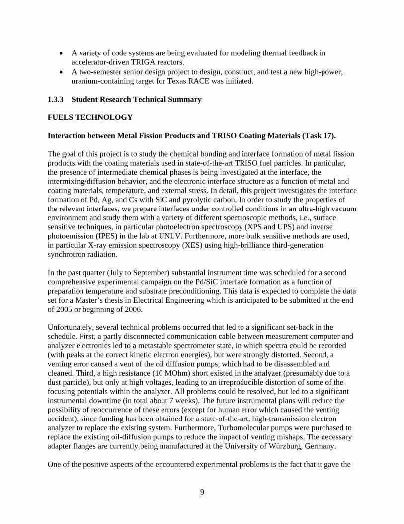
students (undergraduate and graduate alike) in the group an unusual opportunity to learn about crucial aspects in the operation of high-end ultra-high vacuum equipment, in particular with respect to computer communication, electron optics, high voltage electronics, and vacuum pumping. The group has grown into a close-knit nine-member team over the summer and is pictured in Figure 1.
Figure 1. Picture of the Task 19 group.
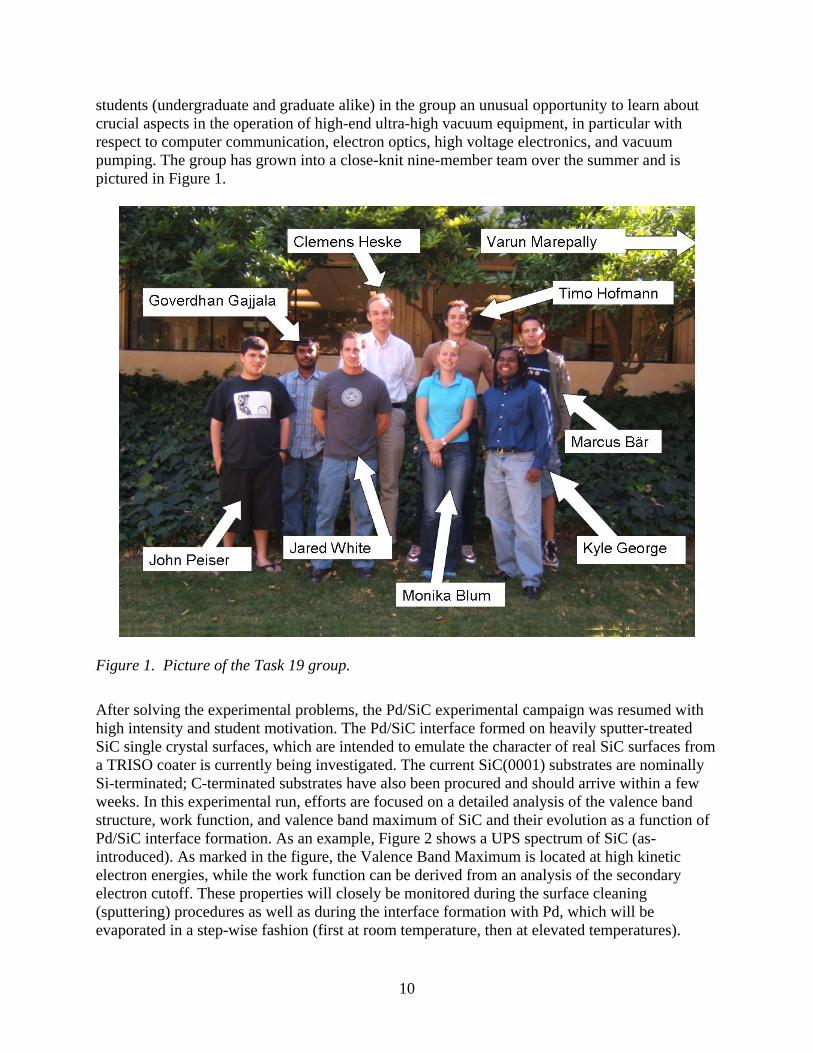
After solving the experimental problems, the Pd/SiC experimental campaign was resumed with high intensity and student motivation. The Pd/SiC interface formed on heavily sputter-treated SiC single crystal surfaces, which are intended to emulate the character of real SiC surfaces from a TRISO coater is currently being investigated. The current SiC(0001) substrates are nominally Si-terminated; C-terminated substrates have also been procured and should arrive within a few weeks. In this experimental run, efforts are focused on a detailed analysis of the valence band structure, work function, and valence band maximum of SiC and their evolution as a function of Pd/SiC interface formation. As an example, Figure 2 shows a UPS spectrum of SiC (as-introduced). As marked in the figure, the Valence Band Maximum is located at high kinetic electron energies, while the work function can be derived from an analysis of the secondary electron cutoff. These properties will closely be monitored during the surface cleaning (sputtering) procedures as well as during the interface formation with Pd, which will be evaporated in a step-wise fashion (first at room temperature, then at elevated temperatures).
11
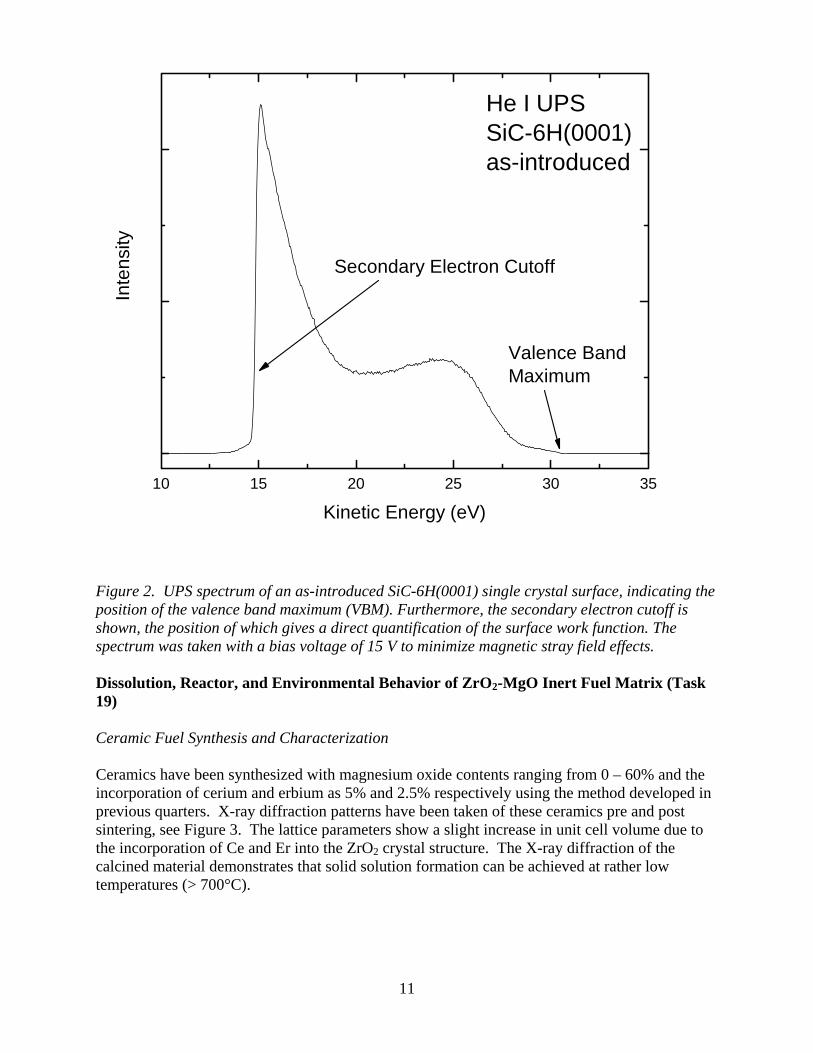
Figure 2. UPS spectrum of an as-introduced SiC-6H(0001) single crystal surface, indicating the position of the valence band maximum (VBM). Furthermore, the secondary electron cutoff is shown, the position of which gives a direct quantification of the surface work function. The spectrum was taken with a bias voltage of 15 V to minimize magnetic stray field effects. Dissolution, Reactor, and Environmental Behavior of ZrO2-MgO Inert Fuel Matrix (Task 19) Ceramic Fuel Synthesis and Characterization Ceramics have been synthesized with magnesium oxide contents ranging from 0 – 60% and the incorporation of cerium and erbium as 5% and 2.5% respectively using the method developed in previous quarters. X-ray diffraction patterns have been taken of these ceramics pre and post sintering, see Figure 3. The lattice parameters show a slight increase in unit cell volume due to the incorporation of Ce and Er into the ZrO2 crystal structure. The X-ray diffraction of the calcined material demonstrates that solid solution formation can be achieved at rather low temperatures (> 700°C).
10 15 20 25 30 35
Inte
nsity
Kinetic Energy (eV)
He I UPSSiC-6H(0001)as-introduced
Secondary Electron Cutoff
Valence BandMaximum
12
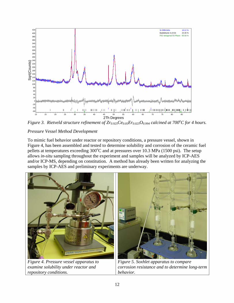
Figure 3. Rietveld structure refinement of Zr0.925Ce0.05Er0.025O0.994 calcined at 700oC for 4 hours. Pressure Vessel Method Development To mimic fuel behavior under reactor or repository conditions, a pressure vessel, shown in Figure 4, has been assembled and tested to determine solubility and corrosion of the ceramic fuel pellets at temperatures exceeding 300oC and at pressures over 10.3 MPa (1500 psi). The setup allows in-situ sampling throughout the experiment and samples will be analyzed by ICP-AES and/or ICP-MS, depending on constitution. A method has already been written for analyzing the samples by ICP-AES and preliminary experiments are underway.
Figure 4. Pressure vessel apparatus to examine solubility under reactor and repository conditions.
Figure 5. Soxhlet apparatus to compare corrosion resistance and to determine long-term behavior.
2Th Degrees85807570656055504540353025201510
Sqr
t(Cou
nts)
420
400
380
360
340
320
300
280
260
240
220
200
180
160
140
120
100
80
60
40
20
0
-20
-40
-60
Si-SRM 640c 10.12 %Baddeleyite m-ZrO2 24.30 %PSZ tetragonal SS Phase 65.58 %
13
Soxhlet Solubility Studies To determine the corrosion resistance of the ceramics, fuel pellets are placed via a cellulose thimble in a Soxhlet apparatus, and the pellets are continuously contacted with distilled hot water (65-70oC) as seen in Figure 5. To evaluation this type of experiments, the specific mass loss will be determined over an extended time period (typically 2,000 hrs). The specific mass loss is characterized by a first order reaction and allows the extrapolation of long-term behavior. The far goal of our solubility and corrosion studies is not only to provide thermodynamic and kinetic data, but also to provide a suitable strategy for the reprocessing of inert matrix fuels. Ceramic Solubility in Reprocessing Conditions Experiments with refluxing nitric acid were unsuccessful in dissolving measurable amounts of the ceramic at high concentrations of zirconium. Future experiments will focus on finding alternatives to nitric acid, such as hydrochloric, hydrochloric/nitric, or perhaps using small amounts of hydrofluoric acid in nitric acid. Reactor Physics Calculations All reactor physics calculations were performed with the ELCOS code system, which was developed for static simulations of Pressurized and Boiling Water Reactors. ELCOS consists of the following four computer codes:
• ETOBOX code generates a group-wise (respectively point-wise in the resonance range) cross-section library from a basic library in ENDF/B-format.
• BOXER code performs cell and two-dimensional transport and depletion calculations. It produces state variable dependant cross section library for 3D full core simulations.
• CORCOD code computes interpolation coefficients based on the BOXER results. These coefficients are later used in the three-dimensional calculations.
• SILWER code performs three-dimensional neutronic calculations with thermal hydraulic feedbacks of the reactor core..
The model for standard 4-Loop 3358 MWth PWR loaded with standard UO2 fuel assemblies operating at 18 calendar months power cycle was developed. The basic set of most important neutronic characteristics was calculated with the developed core model. This set of parameters will serve as a basis for comparison with fertile free fuel core designs to be developed in the next tasks. Second, the existing fertile free core design reported in elsewhere was evaluated independently in order to confirm the available core modeling tools capabilities. The results obtained in this task were compared with those in the literature. Very good agreement was observed in all parameters available for comparison: critical boron letdown curve, power peaking factors, and actinides mass balances. The existence of small differences was attributed to the uncertainty in some of the model parameters not published, e.g. radial and axial fuel burnup distributions of the equilibrium core.
14
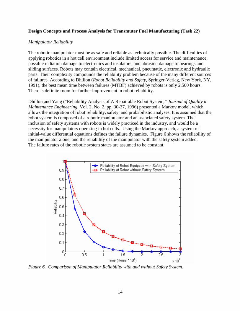
Design Concepts and Process Analysis for Transmuter Fuel Manufacturing (Task 22) Manipulator Reliability The robotic manipulator must be as safe and reliable as technically possible. The difficulties of applying robotics in a hot cell environment include limited access for service and maintenance, possible radiation damage to electronics and insulators, and abrasion damage to bearings and sliding surfaces. Robots may contain electrical, mechanical, pneumatic, electronic and hydraulic parts. Their complexity compounds the reliability problem because of the many different sources of failures. According to Dhillon (Robot Reliability and Safety, Springer-Verlag, New York, NY, 1991), the best mean time between failures (MTBF) achieved by robots is only 2,500 hours. There is definite room for further improvement in robot reliability. Dhillon and Yang (“Reliability Analysis of A Repairable Robot System,” Journal of Quality in Maintenance Engineering, Vol. 2, No. 2, pp. 30-37, 1996) presented a Markov model, which allows the integration of robot reliability, safety, and probabilistic analyses. It is assumed that the robot system is composed of a robotic manipulator and an associated safety system. The inclusion of safety systems with robots is widely practiced in the industry, and would be a necessity for manipulators operating in hot cells. Using the Markov approach, a system of initial-value differential equations defines the failure dynamics. Figure 6 shows the reliability of the manipulator alone, and the reliability of the manipulator with the safety system added. The failure rates of the robotic system states are assumed to be constant.
Figure 6. Comparison of Manipulator Reliability with and without Safety System.
15
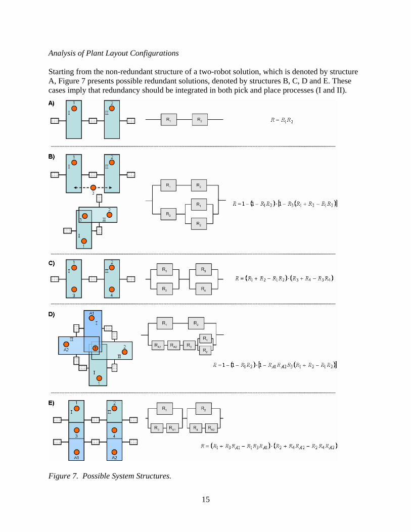
Analysis of Plant Layout Configurations Starting from the non-redundant structure of a two-robot solution, which is denoted by structure A, Figure 7 presents possible redundant solutions, denoted by structures B, C, D and E. These cases imply that redundancy should be integrated in both pick and place processes (I and II).
Figure 7. Possible System Structures.
16
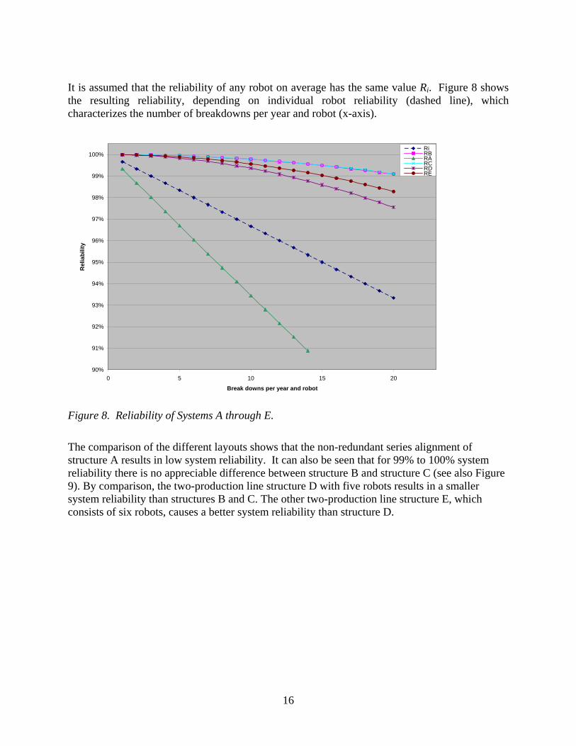
It is assumed that the reliability of any robot on average has the same value Ri. Figure 8 shows the resulting reliability, depending on individual robot reliability (dashed line), which characterizes the number of breakdowns per year and robot (x-axis).
90%
91%
92%
93%
94%
95%
96%
97%
98%
99%
100%
0 5 10 15 20
Break downs per year and robot
Rel
iabi
lity
RiRBRARCRDRE
Figure 8. Reliability of Systems A through E.
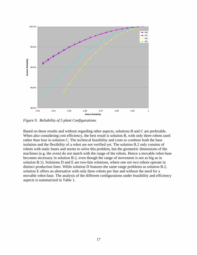
The comparison of the different layouts shows that the non-redundant series alignment of structure A results in low system reliability. It can also be seen that for 99% to 100% system reliability there is no appreciable difference between structure B and structure C (see also Figure 9). By comparison, the two-production line structure D with five robots results in a smaller system reliability than structures B and C. The other two-production line structure E, which consists of six robots, causes a better system reliability than structure D.
17
98.0%
98.5%
99.0%
99.5%
100.0%
0.93 0.94 0.95 0.96 0.97 0.98 0.99 1
Robot Reliability
Syst
em R
elia
bilit
y
RBRCRDRE
Figure 9. Reliability of 5 plant Configurations.
Based on these results and without regarding other aspects, solutions B and C are preferable. When also considering cost efficiency, the best result is solution B, with only three robots used rather than four in solution C. The technical feasibility and costs to combine both the base isolation and the flexibility of a robot are not verified yet. The solution B.2 only consists of robots with static bases and seems to solve this problem, but the geometric dimensions of the machines (e.g. the oven) do not match with the range of the robots. Hence a movable robot base becomes necessary in solution B.2, even though the range of movement is not as big as in solution B.1). Solutions D and E are two-line solutions, where one ore two robots operate in distinct production lines. While solution D features the same range problems as solution B.2, solution E offers an alternative with only three robots per line and without the need for a movable robot base. The analysis of the different configurations under feasibility and efficiency aspects is summarized in Table 1.
18
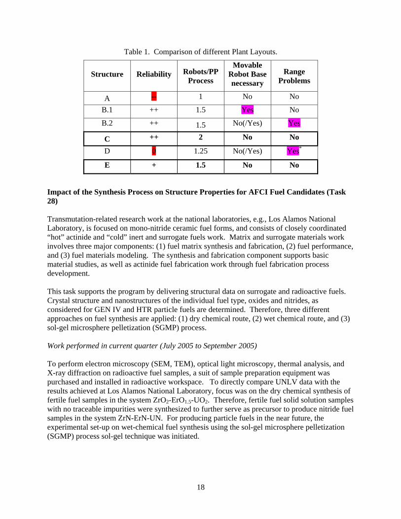
Table 1. Comparison of different Plant Layouts.
Structure Reliability Robots/PP Process
Movable Robot Base necessary
Range Problems
A -- 1 No No
B.1 ++ 1.5 Yes No
B.2 ++ 1.5 No(/Yes) Yes
C ++ 2 No No
D 0 1.25 No(/Yes) Yes*
E + 1.5 No No
Impact of the Synthesis Process on Structure Properties for AFCI Fuel Candidates (Task 28) Transmutation-related research work at the national laboratories, e.g., Los Alamos National Laboratory, is focused on mono-nitride ceramic fuel forms, and consists of closely coordinated “hot” actinide and “cold” inert and surrogate fuels work. Matrix and surrogate materials work involves three major components: (1) fuel matrix synthesis and fabrication, (2) fuel performance, and (3) fuel materials modeling. The synthesis and fabrication component supports basic material studies, as well as actinide fuel fabrication work through fuel fabrication process development. This task supports the program by delivering structural data on surrogate and radioactive fuels. Crystal structure and nanostructures of the individual fuel type, oxides and nitrides, as considered for GEN IV and HTR particle fuels are determined. Therefore, three different approaches on fuel synthesis are applied: (1) dry chemical route, (2) wet chemical route, and (3) sol-gel microsphere pelletization (SGMP) process. Work performed in current quarter (July 2005 to September 2005)
To perform electron microscopy (SEM, TEM), optical light microscopy, thermal analysis, and X-ray diffraction on radioactive fuel samples, a suit of sample preparation equipment was purchased and installed in radioactive workspace. To directly compare UNLV data with the results achieved at Los Alamos National Laboratory, focus was on the dry chemical synthesis of fertile fuel samples in the system ZrO2-ErO1.5-UO2. Therefore, fertile fuel solid solution samples with no traceable impurities were synthesized to further serve as precursor to produce nitride fuel samples in the system ZrN-ErN-UN. For producing particle fuels in the near future, the experimental set-up on wet-chemical fuel synthesis using the sol-gel microsphere pelletization (SGMP) process sol-gel technique was initiated.
19
Zirconia-based Ceramic Fuel in the System ZrO2-ErO1.5-UO2
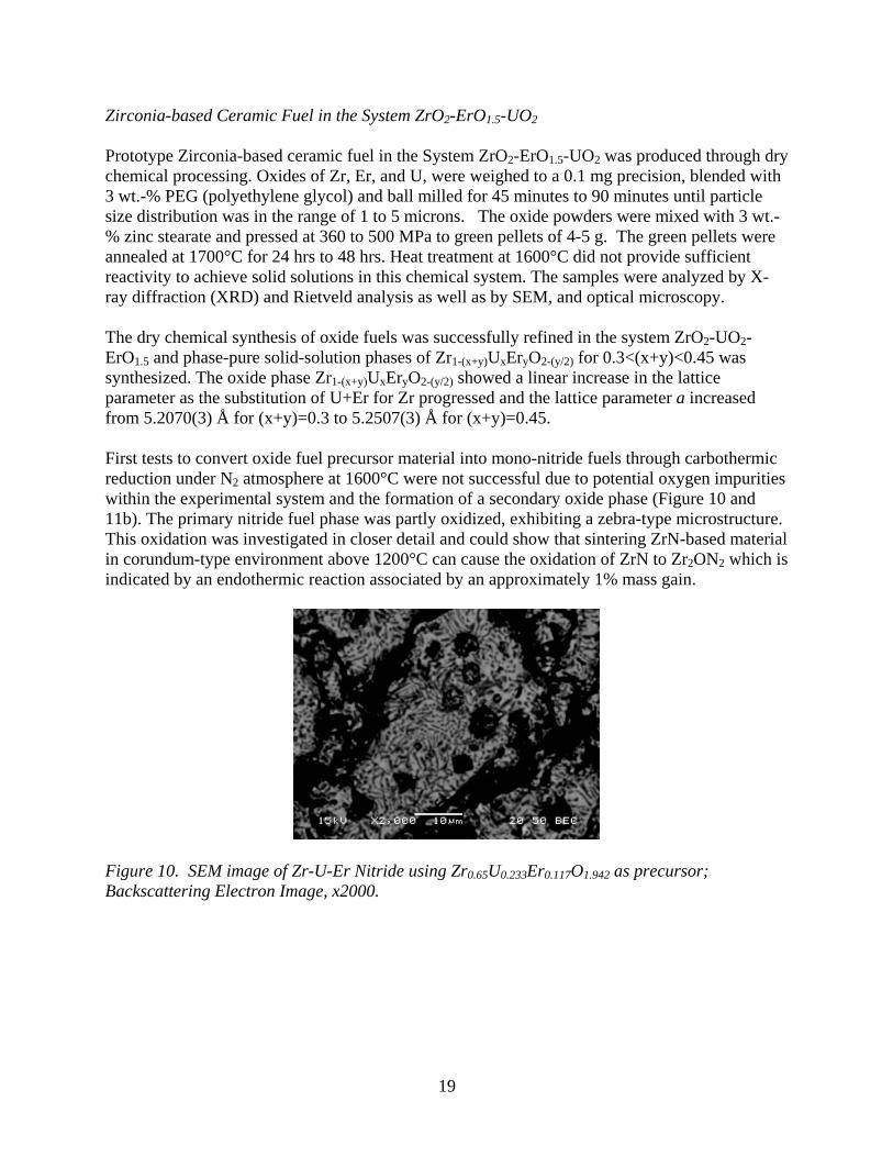
Prototype Zirconia-based ceramic fuel in the System ZrO2-ErO1.5-UO2 was produced through dry chemical processing. Oxides of Zr, Er, and U, were weighed to a 0.1 mg precision, blended with 3 wt.-% PEG (polyethylene glycol) and ball milled for 45 minutes to 90 minutes until particle size distribution was in the range of 1 to 5 microns. The oxide powders were mixed with 3 wt.-% zinc stearate and pressed at 360 to 500 MPa to green pellets of 4-5 g. The green pellets were annealed at 1700°C for 24 hrs to 48 hrs. Heat treatment at 1600°C did not provide sufficient reactivity to achieve solid solutions in this chemical system. The samples were analyzed by X-ray diffraction (XRD) and Rietveld analysis as well as by SEM, and optical microscopy. The dry chemical synthesis of oxide fuels was successfully refined in the system ZrO2-UO2-ErO1.5 and phase-pure solid-solution phases of Zr1-(x+y)UxEryO2-(y/2) for 0.3<(x+y)<0.45 was synthesized. The oxide phase Zr1-(x+y)UxEryO2-(y/2) showed a linear increase in the lattice parameter as the substitution of U+Er for Zr progressed and the lattice parameter a increased from 5.2070(3) Å for (x+y)=0.3 to 5.2507(3) Å for (x+y)=0.45. First tests to convert oxide fuel precursor material into mono-nitride fuels through carbothermic reduction under N2 atmosphere at 1600°C were not successful due to potential oxygen impurities within the experimental system and the formation of a secondary oxide phase (Figure 10 and 11b). The primary nitride fuel phase was partly oxidized, exhibiting a zebra-type microstructure. This oxidation was investigated in closer detail and could show that sintering ZrN-based material in corundum-type environment above 1200°C can cause the oxidation of ZrN to Zr2ON2 which is indicated by an endothermic reaction associated by an approximately 1% mass gain.
Figure 10. SEM image of Zr-U-Er Nitride using Zr0.65U0.233Er0.117O1.942 as precursor; Backscattering Electron Image, x2000.
20
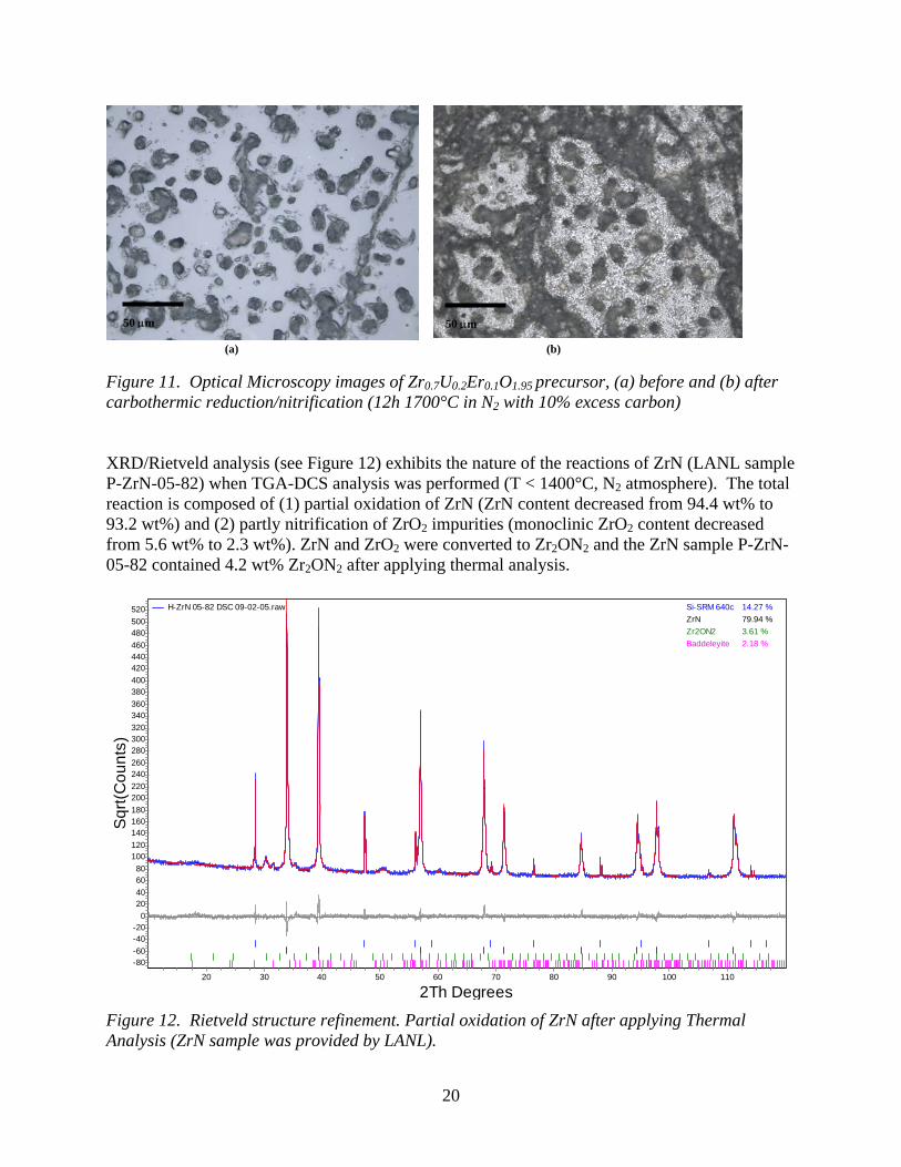
Figure 11. Optical Microscopy images of Zr0.7U0.2Er0.1O1.95 precursor, (a) before and (b) after carbothermic reduction/nitrification (12h 1700°C in N2 with 10% excess carbon) XRD/Rietveld analysis (see Figure 12) exhibits the nature of the reactions of ZrN (LANL sample P-ZrN-05-82) when TGA-DCS analysis was performed (T < 1400°C, N2 atmosphere). The total reaction is composed of (1) partial oxidation of ZrN (ZrN content decreased from 94.4 wt% to 93.2 wt%) and (2) partly nitrification of ZrO2 impurities (monoclinic ZrO2 content decreased from 5.6 wt% to 2.3 wt%). ZrN and ZrO2 were converted to Zr2ON2 and the ZrN sample P-ZrN-05-82 contained 4.2 wt% Zr2ON2 after applying thermal analysis.
2Th Degrees1101009080706050403020
Sqr
t(Cou
nts)
520500480460440420400380360340320300280260240220200180160140120100
806040200
-20-40-60-80
H-ZrN 05-82 DSC 09-02-05.raw Si-SRM 640c 14.27 %ZrN 79.94 %Zr2ON2 3.61 %Baddeleyite 2.18 %
Figure 12. Rietveld structure refinement. Partial oxidation of ZrN after applying Thermal Analysis (ZrN sample was provided by LANL).
50 μm
(a) (b)
50 μm50 μm
21
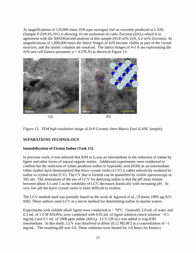
At magnifications of 120,000 times ZrN-type surrogate fuel as currently produced at LANL (Sample P-ZrN 05-101) is showing 10 nm inclusions of cubic Zirconia (ZrO2) which is in agreement with the XRD/Rietveld analysis of this sample (93.8 wt% ZrN, 6.2 wt% Zirconia). At magnifications of 1,000,000 times the lattice fringes of ZrN become visible as part of the crystal structure, and the atomic columns are resolved. The lattice fringes of 4-5 Å are representing the ZrN unit cell (lattice parameter a = 4.578 Å) as shown in Figure 13.
Figure 13. TEM high resolution image of ZrN Ceramic Inert Matrix Fuel (LANL Sample).
SEPARATIONS TECHNOLOGY Immobilization of Fission Iodine (Task 15). In previous work, it was inferred that IOH or I2 was an intermediate in the reduction of iodate by lignin and other forms of natural organic matter. Additional experiments were conducted to confirm hat the reduction of iodate produces iodine or hypoiodic acid (IOH) as an intermediate. Other studies have demonstrated that leuco crystal violet (LCV) is rather selectively oxidized by iodine to crystal violet (CV). The CV that is formed can be quantified by visible spectroscopy at 592 nm. The limitations of the use of LCV for detecting iodine is that the pH must remain between about 3.5 and 5 as the solubility of LCV decreases drastically with increasing pH. At very low pH the leuco crystal violet is more difficult to oxidize. The LCV method used was partially based on the work of Agrawal et al., (Talanta 1999, pg 923-928). These authors used LCV as a micro method for determining iodine in marine waters. Experiments with soluble alkali lignin were conducted at ~ 70oC. Generally 2.8 mL of water and 0.2 mL of 1.0 M KH2PO4 were combined with 0.05 mL of lignin solution (stock solution ~0.5 mg/mL) and 0.1 mL of 1000 ppm iodate (KIO3). LCV (50 uL) was added to trap IOH intermediate. In this study, LCV was dissolved in dilute (0.12 M) HCl at a concentration of ~1 mg/mL. The resulting pH was 3.8. These solutions were heated for 1-6 hours for kinetics
50 nm x 120,000
5 nm x 1,000,000
4-5 Å
a = 4.578 Å
(a) (b)
22
experiments. Some blanks without lignin (but with iodate) were also run. These experiments demonstrated that iodate is capable of slowly oxidizing LCV. The LCV response was calibrated against iodine concentration using the stock (saturated iodine) solution. This calibration was done in a stirred cell. Iodine was added in small increments and the absorbance at 592 nm was recorded. Iodine in the stock solution was determined using the DPD method outlined in a previous report. A series of heating experiments (at ~70C) aimed at determining what functional groups in alkali lignin were reducing the iodate were performed. Heating experiments were done with p-hydroxybenzoic acid, vanillic acid, vanillin and syringic acid. None of these lignin type compounds reduced iodate at an appreciable rate. Rhamnose (a reducing sugar) was also tried but also failed to reduce iodate at a significant rate. In all of these experiments, the reducing agent added as 50 uL of a 50-mg/100 mL solution. All experiments were conducted at pH ~4. Because the chemopyrolysis of alkali lignin (which reduced iodate significantly) showed a strong signal from diphenols, it was decided to try dihydroquinone (1,4 dihydroxy benzene, H2Q) as a reducing agent. Dihydroquinone rapidly reduced iodate to IOH which subsequently oxidized leuco-crystal violet. This reaction proceeded rapidly at 69C and was easily observable at lower temperatures so that it could be studied by UV/Vis spectroscopy. In order to rationalize the data, the possibility that the reaction proceeded with the following fundamental steps and associated rate constants was considered. Because all experiments were conducted at the same pH, the pH dependence of the various reactions is assumed to be incorporated into the rate constants. H2Q +IO3
-→ IO2-+ Q +H2O (reaction 1 - k1)
H2Q + H++IO2
-→IOH + Q + H2O (reaction 2 - k2) H2Q+ IOH → I- + Q+H2O + H+ (reaction 3 - k3) The colorimetric reaction is: LCV +IOH → CV + I- +H2O (reaction 4 - kc)
]Q][IO[Hk-=dt
]d[IO -321
-3 (5)
Assuming that IO2
- concentration is in a steady state.
]IO][QH[k-]IO][QH[k=0=dt
dIO -322
-321
-2 (6)
In addition it was assumed that in the presence of a sink like LCV that IOH is in a steady state.
23
]IOH][LCV[k-]IOH][QH[k-]IO][QH[k=0=dt
]IOH[dc23
-222 (7)
Solving for IOH and IO2
- in terms of iodate, hydroquinone and LCV the following equation is found:
R=]LCV[k+]QH[k
]IO][QH[k]LCV[xk=
dtdCV
c23
-321c (8)
Where R is the rate of color formation.
]IO][QH[kLCV
+]IO[kk
k=
R1
-321
-31c
3 (9)
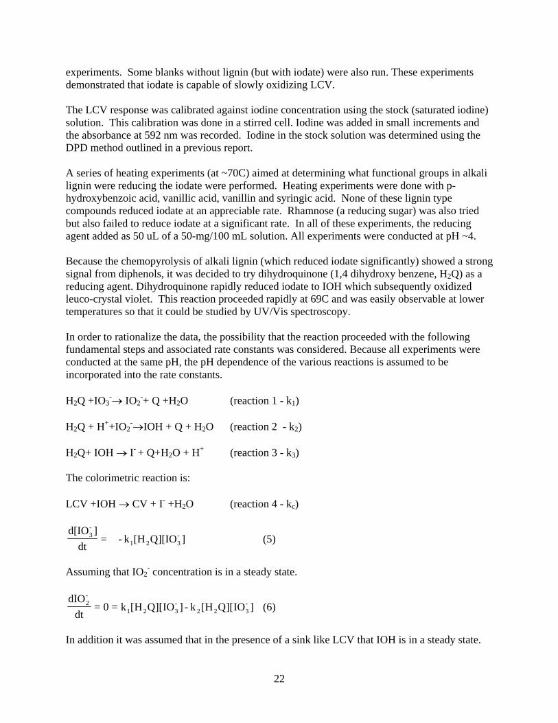
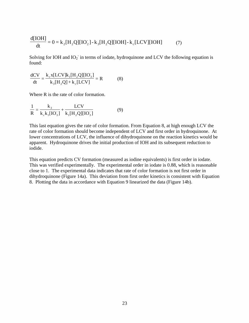
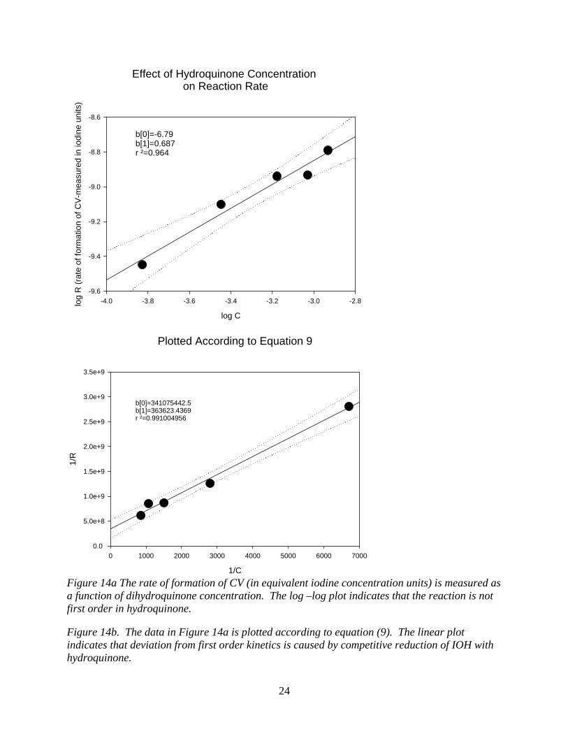
This last equation gives the rate of color formation. From Equation 8, at high enough LCV the rate of color formation should become independent of LCV and first order in hydroquinone. At lower concentrations of LCV, the influence of dihydroquinone on the reaction kinetics would be apparent. Hydroquinone drives the initial production of IOH and its subsequent reduction to iodide. This equation predicts CV formation (measured as iodine equivalents) is first order in iodate. This was verified experimentally. The experimental order in iodate is 0.88, which is reasonable close to 1. The experimental data indicates that rate of color formation is not first order in dihydroquinone (Figure 14a). This deviation from first order kinetics is consistent with Equation 8. Plotting the data in accordance with Equation 9 linearized the data (Figure 14b).
24
Effect of Hydroquinone Concentration on Reaction Rate
log C
-4.0 -3.8 -3.6 -3.4 -3.2 -3.0 -2.8log
R (r
ate
of fo
rmat
ion
of C
V-m
easu
red
in io
dine
uni
ts)
-9.6
-9.4
-9.2
-9.0
-8.8
-8.6
b[0]=-6.79b[1]=0.687r ²=0.964
Plotted According to Equation 9
1/C
0 1000 2000 3000 4000 5000 6000 7000
1/R
0.0
5.0e+8
1.0e+9
1.5e+9
2.0e+9
2.5e+9
3.0e+9
3.5e+9
b[0]=341075442.5b[1]=363623.4369r ²=0.991004956
Figure 14a The rate of formation of CV (in equivalent iodine concentration units) is measured as a function of dihydroquinone concentration. The log –log plot indicates that the reaction is not first order in hydroquinone. Figure 14b. The data in Figure 14a is plotted according to equation (9). The linear plot indicates that deviation from first order kinetics is caused by competitive reduction of IOH with hydroquinone.
25
The results in Figure 14b indicate that that the deviation of the color formation kinetics from first order (in H2Q) is a result of the reduction of IOH (or I2) to I- competing with the reaction with LCV. A further (but somewhat qualitative) indication of the IOH intermediate was obtained by running the iodate – H2Q reaction in the presence of vanillin, vanillic acid and p-hydroxybenzoic acid. The result was partial iodination of the three substrates. These results are consistent with previous observations that iodate reacts with natural organic matter by reduction and partial incorporation into the NOM matrix. This interaction may arrest migration of iodate in the environment and has important implications for the fate of iodine produced by radioactive decay and fission. Fluorapatite Waste Forms (Task 16). Fluorapatite, fluorinated calcium phosphate, has been identified as a potential matrix for the entombment of the zirconium fluoride fission product waste stream from the proposed FLEX process. If the efficacy of fluorapatite-based waste-storage can be demonstrated, then new and potentially more-efficient options for handling and separating high-level wastes, based on fluoride-salt extraction, will become feasible. This task developed a dual-path research project to develop a process to fabricate a synthetic fluorapatite waste form for the ZrF4, FP waste stream, characterize the waste form, examine its performance under environmental conditions, and correlate the behavior of the waste form with natural analogs. Characterization of the material was accomplished through probing the molecular-scale electronic and geometric structure of the materials in order to relate them to macroscopic properties, with the goal of developing techniques to evaluate and predict the performance of different waste-form materials. This quarter, both graduate students prepared for their graduation at UNLV and spent their time on writing their theses and preparing for their Master’s degree defense. Chirantha Rodrigo successfully completed his Master’s degree at UNLV and enrolled in a PhD program elsewhere. Chinthaka Silva submitted his thesis to the graduation committee and will have his defense in October. Development of Integrated Process Simulation System Model for Spent Fuel Treatment Facility Design (Task 24). Refinement of the TRPSEMPro Software Package The intention of developing TRPSEMPro software was to accelerate research progress and to efficiently analyze research results. The implementation of the database system was completed. In response to a request from ANL, more research notes and details are to be included into each flowsheet simulation run. More information can be further documented into the database for
26
later validation and progress tracking. The analysis result query process takes time to complete, so a progress indication was implemented.
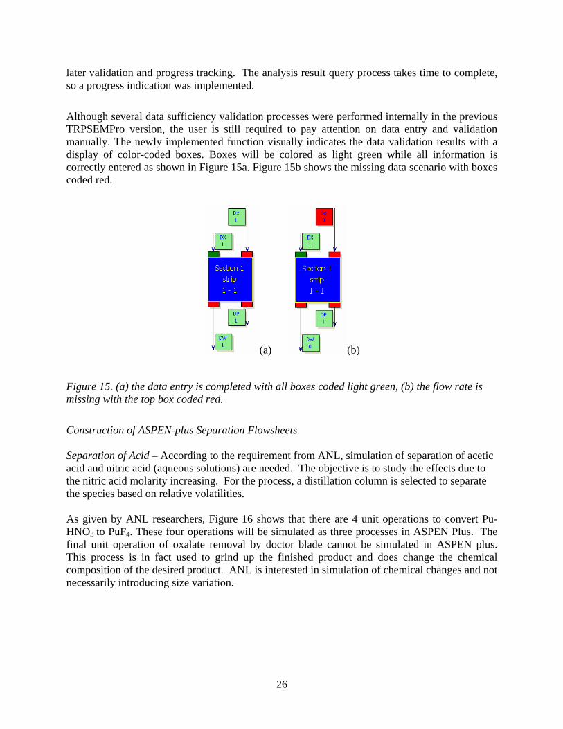
Although several data sufficiency validation processes were performed internally in the previous TRPSEMPro version, the user is still required to pay attention on data entry and validation manually. The newly implemented function visually indicates the data validation results with a display of color-coded boxes. Boxes will be colored as light green while all information is correctly entered as shown in Figure 15a. Figure 15b shows the missing data scenario with boxes coded red.
(a) (b)
Figure 15. (a) the data entry is completed with all boxes coded light green, (b) the flow rate is missing with the top box coded red.
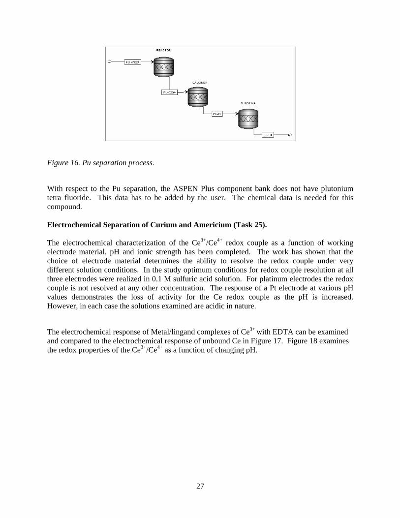
Construction of ASPEN-plus Separation Flowsheets Separation of Acid – According to the requirement from ANL, simulation of separation of acetic acid and nitric acid (aqueous solutions) are needed. The objective is to study the effects due to the nitric acid molarity increasing. For the process, a distillation column is selected to separate the species based on relative volatilities. As given by ANL researchers, Figure 16 shows that there are 4 unit operations to convert Pu-HNO3 to PuF4. These four operations will be simulated as three processes in ASPEN Plus. The final unit operation of oxalate removal by doctor blade cannot be simulated in ASPEN plus. This process is in fact used to grind up the finished product and does change the chemical composition of the desired product. ANL is interested in simulation of chemical changes and not necessarily introducing size variation.
27
Figure 16. Pu separation process.
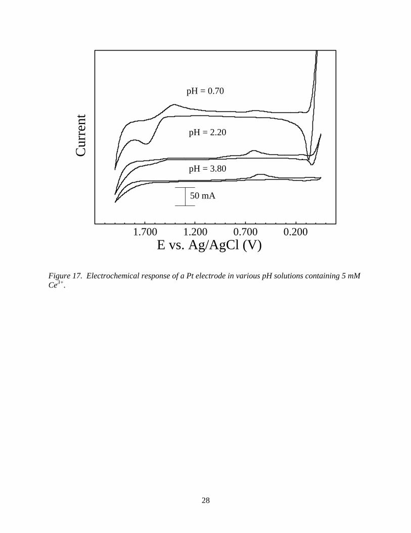
With respect to the Pu separation, the ASPEN Plus component bank does not have plutonium tetra fluoride. This data has to be added by the user. The chemical data is needed for this compound. Electrochemical Separation of Curium and Americium (Task 25). The electrochemical characterization of the Ce3+/Ce4+ redox couple as a function of working electrode material, pH and ionic strength has been completed. The work has shown that the choice of electrode material determines the ability to resolve the redox couple under very different solution conditions. In the study optimum conditions for redox couple resolution at all three electrodes were realized in 0.1 M sulfuric acid solution. For platinum electrodes the redox couple is not resolved at any other concentration. The response of a Pt electrode at various pH values demonstrates the loss of activity for the Ce redox couple as the pH is increased. However, in each case the solutions examined are acidic in nature.
The electrochemical response of Metal/lingand complexes of Ce3+ with EDTA can be examined and compared to the electrochemical response of unbound Ce in Figure 17. Figure 18 examines the redox properties of the Ce3+/Ce4+ as a function of changing pH.
28
1.700 1.200 0.700 0.200
Cur
rent
E vs. Ag/AgCl (V)
50 mA
pH = 0.70
pH = 2.20
pH = 3.80
Figure 17. Electrochemical response of a Pt electrode in various pH solutions containing 5 mM Ce3+.
29
1.7 1.2 0.7 0.2 -0.3 -0.8E vs. Ag/AgCl (V)
pH = 4
pH = 10
pH = 8
pH = 6
pH = 2
pH = 12
1 mA
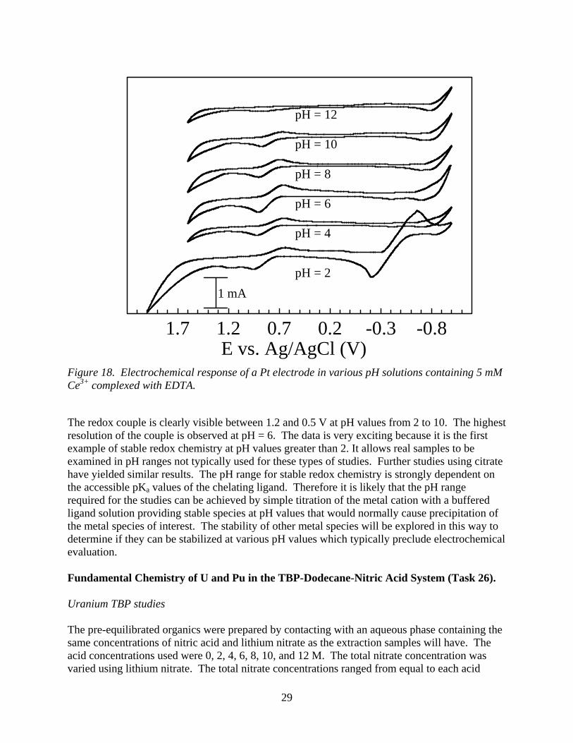
Figure 18. Electrochemical response of a Pt electrode in various pH solutions containing 5 mM Ce3+ complexed with EDTA.
The redox couple is clearly visible between 1.2 and 0.5 V at pH values from 2 to 10. The highest resolution of the couple is observed at pH = 6. The data is very exciting because it is the first example of stable redox chemistry at pH values greater than 2. It allows real samples to be examined in pH ranges not typically used for these types of studies. Further studies using citrate have yielded similar results. The pH range for stable redox chemistry is strongly dependent on the accessible pKa values of the chelating ligand. Therefore it is likely that the pH range required for the studies can be achieved by simple titration of the metal cation with a buffered ligand solution providing stable species at pH values that would normally cause precipitation of the metal species of interest. The stability of other metal species will be explored in this way to determine if they can be stabilized at various pH values which typically preclude electrochemical evaluation. Fundamental Chemistry of U and Pu in the TBP-Dodecane-Nitric Acid System (Task 26). Uranium TBP studies The pre-equilibrated organics were prepared by contacting with an aqueous phase containing the same concentrations of nitric acid and lithium nitrate as the extraction samples will have. The acid concentrations used were 0, 2, 4, 6, 8, 10, and 12 M. The total nitrate concentration was varied using lithium nitrate. The total nitrate concentrations ranged from equal to each acid
30
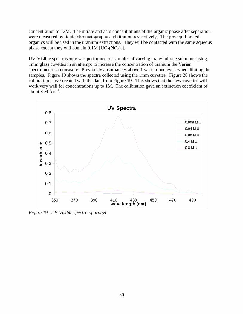
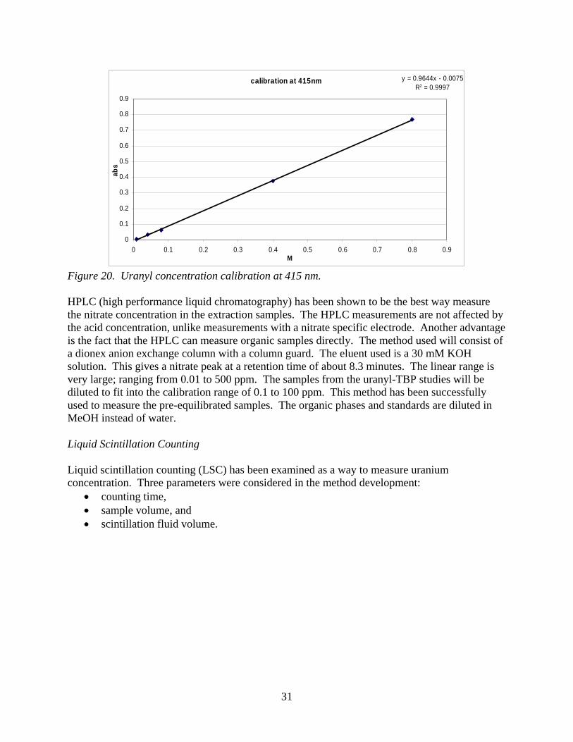
concentration to 12M. The nitrate and acid concentrations of the organic phase after separation were measured by liquid chromatography and titration respectively. The pre-equilibrated organics will be used in the uranium extractions. They will be contacted with the same aqueous phase except they will contain 0.1M [UO2(NO3)2]. UV-Visible spectroscopy was performed on samples of varying uranyl nitrate solutions using 1mm glass cuvettes in an attempt to increase the concentration of uranium the Varian spectrometer can measure. Previously absorbances above 1 were found even when diluting the samples. Figure 19 shows the spectra collected using the 1mm cuvettes. Figure 20 shows the calibration curve created with the data from Figure 19. This shows that the new cuvettes will work very well for concentrations up to 1M. The calibration gave an extinction coefficient of about 8 M-1cm-1.
UV Spectra
0
0.1
0.2
0.3
0.4
0.5
0.6
0.7
0.8
350 370 390 410 430 450 470 490wavelength (nm)
Abs
orba
nce
0.008 M U
0.04 M U
0.08 M U
0.4 M U
0.8 M U
Figure 19. UV-Visible spectra of uranyl
31
calibration at 415nm y = 0.9644x - 0.0075R2 = 0.9997
0
0.1
0.2
0.3
0.4
0.5
0.6
0.7
0.8
0.9
0 0.1 0.2 0.3 0.4 0.5 0.6 0.7 0.8 0.9M
abs
Figure 20. Uranyl concentration calibration at 415 nm.
HPLC (high performance liquid chromatography) has been shown to be the best way measure the nitrate concentration in the extraction samples. The HPLC measurements are not affected by the acid concentration, unlike measurements with a nitrate specific electrode. Another advantage is the fact that the HPLC can measure organic samples directly. The method used will consist of a dionex anion exchange column with a column guard. The eluent used is a 30 mM KOH solution. This gives a nitrate peak at a retention time of about 8.3 minutes. The linear range is very large; ranging from 0.01 to 500 ppm. The samples from the uranyl-TBP studies will be diluted to fit into the calibration range of 0.1 to 100 ppm. This method has been successfully used to measure the pre-equilibrated samples. The organic phases and standards are diluted in MeOH instead of water. Liquid Scintillation Counting Liquid scintillation counting (LSC) has been examined as a way to measure uranium concentration. Three parameters were considered in the method development:
• counting time, • sample volume, and • scintillation fluid volume.
32
effect of counting time
0.0E+00
5.0E-05
1.0E-04
1.5E-04
2.0E-04
0 2 4 6hours
MD
L (M
)
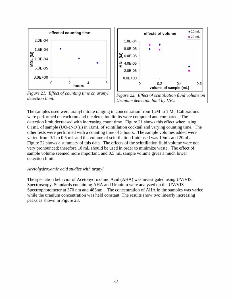
Figure 21. Effect of counting time on uranyl detection limit.
effects of volume
0.0E+00
2.0E-05
4.0E-05
6.0E-05
8.0E-05
1.0E-04
0 0.2 0.4 0.6volume of sample (mL)
MD
L (M
)
10 mL20 mL
Figure 22. Effect of scintillation fluid volume on Uranium detection limit by LSC.
The samples used were uranyl nitrate ranging in concentration from 1μM to 1 M. Calibrations were performed on each run and the detection limits were computed and compared. The detection limit decreased with increasing count time. Figure 21 shows this effect when using 0.1mL of sample (UO2(NO3)2) in 10mL of scintillation cocktail and varying counting time. The other tests were performed with a counting time of 5 hours. The sample volumes added were varied from 0.1 to 0.5 mL and the volume of scintillation fluid used was 10mL and 20mL. Figure 22 shows a summary of this data. The effects of the scintillation fluid volume were not very pronounced; therefore 10 mL should be used in order to minimize waste. The effect of sample volume seemed more important, and 0.5 mL sample volume gives a much lower detection limit.
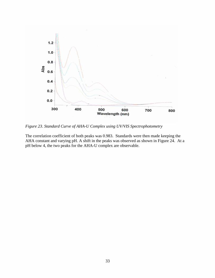
Acetohydroxamic acid studies with uranyl The speciation behavior of Acetohydroxamic Acid (AHA) was investigated using UV/VIS Spectroscopy. Standards containing AHA and Uranium were analyzed on the UV/VIS Spectrophotometer at 370 nm and 483nm . The concentration of AHA in the samples was varied while the uranium concentration was held constant. The results show two linearly increasing peaks as shown in Figure 23.
33
Figure 23. Standard Curve of AHA-U Complex using UV/VIS Spectrophotometry The correlation coefficient of both peaks was 0.983. Standards were then made keeping the AHA constant and varying pH. A shift in the peaks was observed as shown in Figure 24. At a pH below 4, the two peaks for the AHA-U complex are observable.
34
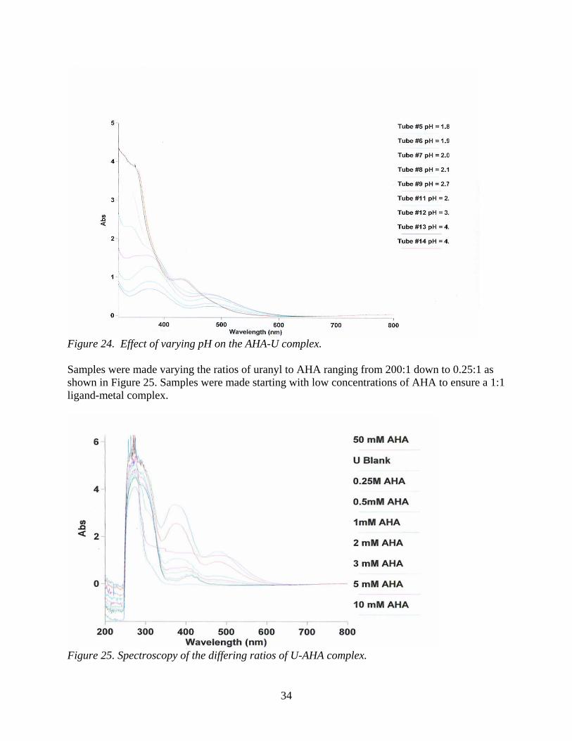
Figure 24. Effect of varying pH on the AHA-U complex. Samples were made varying the ratios of uranyl to AHA ranging from 200:1 down to 0.25:1 as shown in Figure 25. Samples were made starting with low concentrations of AHA to ensure a 1:1 ligand-metal complex.
Figure 25. Spectroscopy of the differing ratios of U-AHA complex.
35
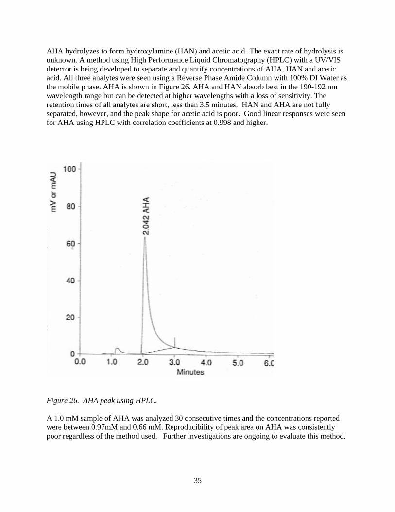
AHA hydrolyzes to form hydroxylamine (HAN) and acetic acid. The exact rate of hydrolysis is unknown. A method using High Performance Liquid Chromatography (HPLC) with a UV/VIS detector is being developed to separate and quantify concentrations of AHA, HAN and acetic acid. All three analytes were seen using a Reverse Phase Amide Column with 100% DI Water as the mobile phase. AHA is shown in Figure 26. AHA and HAN absorb best in the 190-192 nm wavelength range but can be detected at higher wavelengths with a loss of sensitivity. The retention times of all analytes are short, less than 3.5 minutes. HAN and AHA are not fully separated, however, and the peak shape for acetic acid is poor. Good linear responses were seen for AHA using HPLC with correlation coefficients at 0.998 and higher.
Figure 26. AHA peak using HPLC. A 1.0 mM sample of AHA was analyzed 30 consecutive times and the concentrations reported were between 0.97mM and 0.66 mM. Reproducibility of peak area on AHA was consistently poor regardless of the method used. Further investigations are ongoing to evaluate this method.
36
Investigation of Optical Spectroscopy Techniques for On-Line Materials Accountability in the Solvent Extraction Process (Task 29). Laser Laboratory Development In preparation for the delivery and installation of the tunable laser system (expected 10/05), the laser safety program for the laboratory was developed. The program, based on the American National Standards Institute (ANSI) requirements, was developed in collaboration with the UNLV laser safety officer and the UNLV radiation safety officer, and will support work with the new Category IV laser system using the actinide elements. The optical bench was installed in the laboratory, and the power meters and spectrometer were received (installation pending delivery of laser system). Uranium in Aqueous Systems Evaluation of the impact of process conditions (pH, nitrate concentration, etc.) on the spectroscopy and detection limits for uranium in the aqueous stream will be evaluated using the UV-Visible Spectrometer. Initial experiments examining the impact of pH have been performed, with data analysis pending. Uranyl hydroxide was prepared from uranyl nitrate by precipitation using sodium hydroxide solutions. The resulting solid was rinsed in DI water to remove excess NaOH and nitrate, and the washed solid was redissolved in perchloric acid. Hydrogen ion concentrations (pH) were determined in the stock solution was determined by back titration, and the UO2-perchlorate stock was used to prepare nitrate-free samples to evaluate the impact of pH on the detection limit and spectroscopy of U independent of nitrate concentration. Combined Radiation Detection Methods for Assay of Higher Actinides in Separation Processes (Task 30). One technique that has been used in a variety of applications is neutron multiplicity measurement. This is the coincidence measurement of multiple neutrons that are emitted in individual fission events. A Neutron Multiplicity Detector System (NMDS) was developed for TRP Task 6 in collaboration with the V. G. Khlopin Radium Institute (KRI) in St. Petersburg, Russia (see Figure 27). The system has since been extensively tested at UNLV and ISU. The NMDS is a modular system consisting of 64 3He detectors (tubes), electronics, and lead and polyethylene bricks. The modular nature of the systems allows it to be used in a variety of configurations and for a variety of purposes. Examples are measurement of neutron multiplicity from high-power, high-energy spallation targets, detection of fissile materials in cargo systems or luggage, and assay of actinides in fuel or storage containers. In the original KRI-supplied system, the 3He detectors operate at ~6 microsecond timing resolution and collect data from each multiplicity event for a 256-microsecond duration. The data acquisition and analysis system subsequently allows correlation of the neutron multiplicity to each event. Count rate and data acquisition capabilities of the NMDS are currently being expanded in TRP Task 6, “Neutron Multiplicity Measurements for the AFCI Program.” Other equipment at UNLV and ISU that may
37
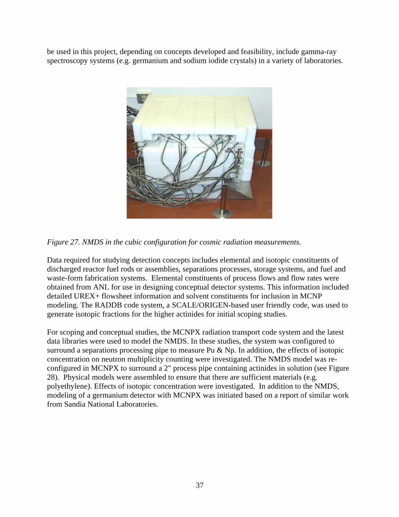
be used in this project, depending on concepts developed and feasibility, include gamma-ray spectroscopy systems (e.g. germanium and sodium iodide crystals) in a variety of laboratories.
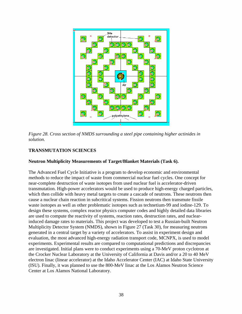
Figure 27. NMDS in the cubic configuration for cosmic radiation measurements. Data required for studying detection concepts includes elemental and isotopic constituents of discharged reactor fuel rods or assemblies, separations processes, storage systems, and fuel and waste-form fabrication systems. Elemental constituents of process flows and flow rates were obtained from ANL for use in designing conceptual detector systems. This information included detailed UREX+ flowsheet information and solvent constituents for inclusion in MCNP modeling. The RADDB code system, a SCALE/ORIGEN-based user friendly code, was used to generate isotopic fractions for the higher actinides for initial scoping studies. For scoping and conceptual studies, the MCNPX radiation transport code system and the latest data libraries were used to model the NMDS. In these studies, the system was configured to surround a separations processing pipe to measure Pu & Np. In addition, the effects of isotopic concentration on neutron multiplicity counting were investigated. The NMDS model was re-configured in MCNPX to surround a 2" process pipe containing actinides in solution (see Figure 28). Physical models were assembled to ensure that there are sufficient materials (e.g. polyethylene). Effects of isotopic concentration were investigated. In addition to the NMDS, modeling of a germanium detector with MCNPX was initiated based on a report of similar work from Sandia National Laboratories.
38
Figure 28. Cross section of NMDS surrounding a steel pipe containing higher actinides in solution. TRANSMUTATION SCIENCES Neutron Multiplicity Measurements of Target/Blanket Materials (Task 6). The Advanced Fuel Cycle Initiative is a program to develop economic and environmental methods to reduce the impact of waste from commercial nuclear fuel cycles. One concept for near-complete destruction of waste isotopes from used nuclear fuel is accelerator-driven transmutation. High-power accelerators would be used to produce high-energy charged particles, which then collide with heavy metal targets to create a cascade of neutrons. These neutrons then cause a nuclear chain reaction in subcritical systems. Fission neutrons then transmute fissile waste isotopes as well as other problematic isotopes such as technetium-99 and iodine-129. To design these systems, complex reactor physics computer codes and highly detailed data libraries are used to compute the reactivity of systems, reaction rates, destruction rates, and nuclear-induced damage rates to materials. This project was developed to test a Russian-built Neutron Multiplicity Detector System (NMDS), shown in Figure 27 (Task 30), for measuring neutrons generated in a central target by a variety of accelerators. To assist in experiment design and evaluation, the most advanced high-energy radiation transport code, MCNPX, is used to model experiments. Experimental results are compared to computational predictions and discrepancies are investigated. Initial plans were to conduct experiments using a 70-MeV proton cyclotron at the Crocker Nuclear Laboratory at the University of California at Davis and/or a 20 to 40 MeV electron linac (linear accelerator) at the Idaho Accelerator Center (IAC) at Idaho State University (ISU). Finally, it was planned to use the 800-MeV linac at the Los Alamos Neutron Science Center at Los Alamos National Laboratory.
39
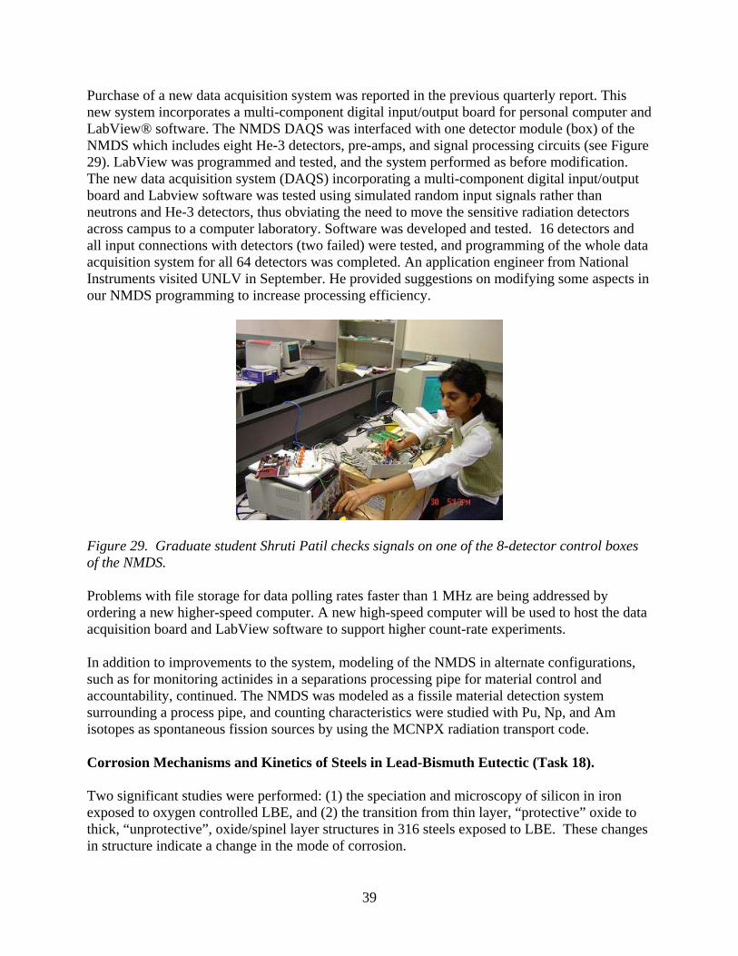
Purchase of a new data acquisition system was reported in the previous quarterly report. This new system incorporates a multi-component digital input/output board for personal computer and LabView® software. The NMDS DAQS was interfaced with one detector module (box) of the NMDS which includes eight He-3 detectors, pre-amps, and signal processing circuits (see Figure 29). LabView was programmed and tested, and the system performed as before modification. The new data acquisition system (DAQS) incorporating a multi-component digital input/output board and Labview software was tested using simulated random input signals rather than neutrons and He-3 detectors, thus obviating the need to move the sensitive radiation detectors across campus to a computer laboratory. Software was developed and tested. 16 detectors and all input connections with detectors (two failed) were tested, and programming of the whole data acquisition system for all 64 detectors was completed. An application engineer from National Instruments visited UNLV in September. He provided suggestions on modifying some aspects in our NMDS programming to increase processing efficiency.
Figure 29. Graduate student Shruti Patil checks signals on one of the 8-detector control boxes of the NMDS. Problems with file storage for data polling rates faster than 1 MHz are being addressed by ordering a new higher-speed computer. A new high-speed computer will be used to host the data acquisition board and LabView software to support higher count-rate experiments. In addition to improvements to the system, modeling of the NMDS in alternate configurations, such as for monitoring actinides in a separations processing pipe for material control and accountability, continued. The NMDS was modeled as a fissile material detection system surrounding a process pipe, and counting characteristics were studied with Pu, Np, and Am isotopes as spontaneous fission sources by using the MCNPX radiation transport code. Corrosion Mechanisms and Kinetics of Steels in Lead-Bismuth Eutectic (Task 18). Two significant studies were performed: (1) the speciation and microscopy of silicon in iron exposed to oxygen controlled LBE, and (2) the transition from thin layer, “protective” oxide to thick, “unprotective”, oxide/spinel layer structures in 316 steels exposed to LBE. These changes in structure indicate a change in the mode of corrosion.
40
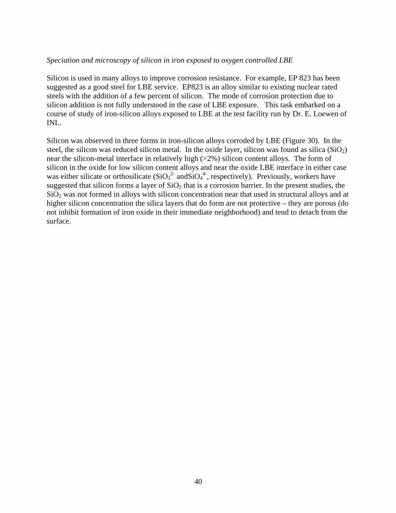
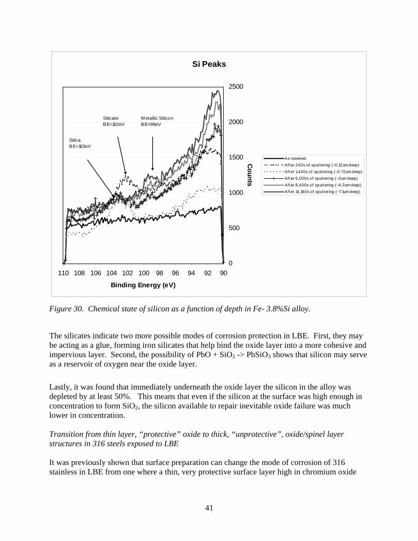
Speciation and microscopy of silicon in iron exposed to oxygen controlled LBE Silicon is used in many alloys to improve corrosion resistance. For example, EP 823 has been suggested as a good steel for LBE service. EP823 is an alloy similar to existing nuclear rated steels with the addition of a few percent of silicon. The mode of corrosion protection due to silicon addition is not fully understood in the case of LBE exposure. This task embarked on a course of study of iron-silicon alloys exposed to LBE at the test facility run by Dr. E. Loewen of INL. Silicon was observed in three forms in iron-silicon alloys corroded by LBE (Figure 30). In the steel, the silicon was reduced silicon metal. In the oxide layer, silicon was found as silica (SiO2) near the silicon-metal interface in relatively high (>2%) silicon content alloys. The form of silicon in the oxide for low silicon content alloys and near the oxide LBE interface in either case was either silicate or orthosilicate (SiO3
2- andSiO44-, respectively). Previously, workers have
suggested that silicon forms a layer of SiO2 that is a corrosion barrier. In the present studies, the SiO2 was not formed in alloys with silicon concentration near that used in structural alloys and at higher silicon concentration the silica layers that do form are not protective – they are porous (do not inhibit formation of iron oxide in their immediate neighborhood) and tend to detach from the surface.
41
Si Peaks
0
500
1000
1500
2000
2500
9092949698100102104106108110
Binding Energy (eV)
Counts
As receivedAfter 240s of sputtering (~0.12um deep)After 1,440s of sputtering (~0.72um deep)After 6,000s of sputtering (~3um deep)After 8,400s of sputtering (~4.2um deep)After 14,160s of sputtering (~7.1um deep)
SilicaBE=103eV
SilicateBE=102eV
M etallic SiliconBE=99eV
Figure 30. Chemical state of silicon as a function of depth in Fe- 3.8%Si alloy.
The silicates indicate two more possible modes of corrosion protection in LBE. First, they may be acting as a glue, forming iron silicates that help bind the oxide layer into a more cohesive and impervious layer. Second, the possibility of PbO + SiO2 -> PbSiO3 shows that silicon may serve as a reservoir of oxygen near the oxide layer.
Lastly, it was found that immediately underneath the oxide layer the silicon in the alloy was depleted by at least 50%. This means that even if the silicon at the surface was high enough in concentration to form SiO2, the silicon available to repair inevitable oxide failure was much lower in concentration. Transition from thin layer, “protective” oxide to thick, “unprotective”, oxide/spinel layer structures in 316 steels exposed to LBE It was previously shown that surface preparation can change the mode of corrosion of 316 stainless in LBE from one where a thin, very protective surface layer high in chromium oxide
42
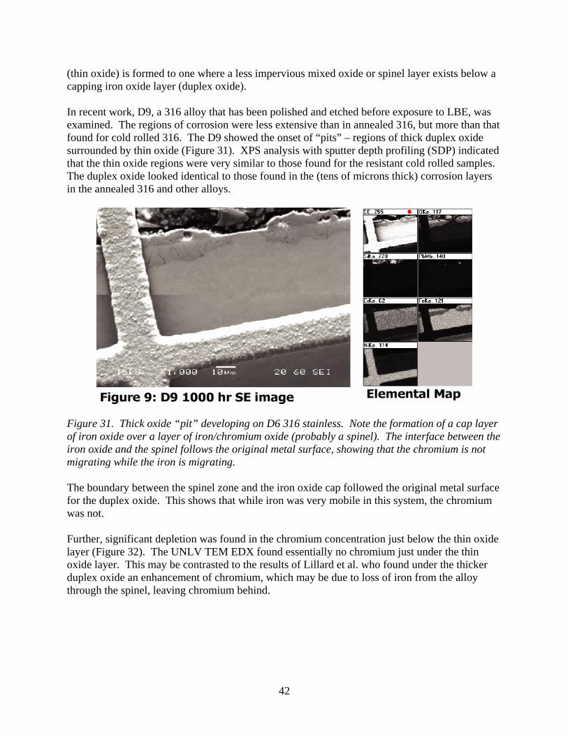
(thin oxide) is formed to one where a less impervious mixed oxide or spinel layer exists below a capping iron oxide layer (duplex oxide). In recent work, D9, a 316 alloy that has been polished and etched before exposure to LBE, was examined. The regions of corrosion were less extensive than in annealed 316, but more than that found for cold rolled 316. The D9 showed the onset of “pits” – regions of thick duplex oxide surrounded by thin oxide (Figure 31). XPS analysis with sputter depth profiling (SDP) indicated that the thin oxide regions were very similar to those found for the resistant cold rolled samples. The duplex oxide looked identical to those found in the (tens of microns thick) corrosion layers in the annealed 316 and other alloys.
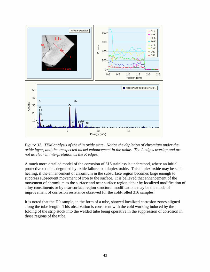
Figure 31. Thick oxide “pit” developing on D6 316 stainless. Note the formation of a cap layer of iron oxide over a layer of iron/chromium oxide (probably a spinel). The interface between the iron oxide and the spinel follows the original metal surface, showing that the chromium is not migrating while the iron is migrating. The boundary between the spinel zone and the iron oxide cap followed the original metal surface for the duplex oxide. This shows that while iron was very mobile in this system, the chromium was not. Further, significant depletion was found in the chromium concentration just below the thin oxide layer (Figure 32). The UNLV TEM EDX found essentially no chromium just under the thin oxide layer. This may be contrasted to the results of Lillard et al. who found under the thicker duplex oxide an enhancement of chromium, which may be due to loss of iron from the alloy through the spinel, leaving chromium behind.
43
Figure 32. TEM analysis of the thin oxide state. Notice the depletion of chromium under the oxide layer, and the unexpected nickel enhancement in the oxide. The L edges overlap and are not as clear in interpretation as the K edges. A much more detailed model of the corrosion of 316 stainless is understood, where an initial protective oxide is degraded by oxide failure to a duplex oxide. This duplex oxide may be self-healing, if the enhancement of chromium in the subsurface region becomes large enough to suppress subsequent movement of iron to the surface. It is believed that enhancement of the movement of chromium to the surface and near surface region either by localized modification of alloy constituents or by near surface region structural modifications may be the mode of improvement of corrosion resistance observed for the cold-rolled 316 samples. It is noted that the D9 sample, in the form of a tube, showed localized corrosion zones aligned along the tube length. This observation is consistent with the cold working induced by the folding of the strip stock into the welded tube being operative in the suppression of corrosion in those regions of the tube.
2 um
1
1
1
1
HAADF Detector
Energy (keV)
Cou
nts
15105
50
40
30
20
10
0
Ni NiNi
Ni
Fe
Fe
Fe
Cr
Cr
Cr
C
O
EDX HAADF Detector Point 1
Position (um)
Cou
nts
2.52.01.51.00.50.0
800
600
400
200
0
Ni-LNi-KFe-LFe-KCr-LCr-KO-KC-K
44
Oxide Film Growth Modeling in LBE Systems (Task 21). New method on enhancement of oxygen transfer in LBE system by forced convection To transport the oxygen into LBE quickly, a pump is used to push the liquid LBE with constant velocity at the inlet as shown in Figure 33. It is assumed that the dissolving oxygen concentration at the liquid surface is a constant. The Lattice Boltzmann method is used to simulate oxygen transport under forced convection in the container. Figure 34 shows the oxygen concentration contours in the container at a given time. Available results indicate the forced convection will enhance the oxygen transfer evidently.
Figure 33. Schematic of the container for an oxygen control system with cover gas.
Figure 34. Oxygen concentration (normalized by dissolving oxygen concentration at the liquid surface) distribution in the container (t =320 s). Cellular automata simulation on oxide growth A positive surface growth model, which is initiated by chemical reactions partially counterbalanced by a poisoning process, is developed for simulating the oxide growth for the steel exposing in liquid LBE. This model which works at a mesoscopic scale is simulated on a two-dimensional lattice. Using a cellular automata method, the snapshots of the simulated positive growth oxide layer are obtained as shown in Figure 35.
st 320=
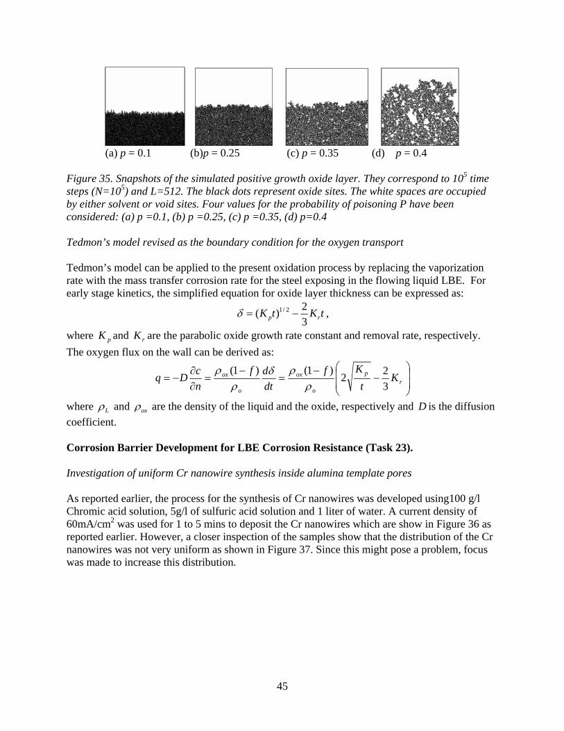
45
(a) p = 0.1 (b)p = 0.25 (c) p = 0.35 (d) p = 0.4 Figure 35. Snapshots of the simulated positive growth oxide layer. They correspond to 105 time steps (N=105) and L=512. The black dots represent oxide sites. The white spaces are occupied by either solvent or void sites. Four values for the probability of poisoning P have been considered: (a) p =0.1, (b) p =0.25, (c) p =0.35, (d) p=0.4 Tedmon’s model revised as the boundary condition for the oxygen transport Tedmon’s model can be applied to the present oxidation process by replacing the vaporization rate with the mass transfer corrosion rate for the steel exposing in the flowing liquid LBE. For early stage kinetics, the simplified equation for oxide layer thickness can be expressed as:
tKtK rp 32)( 2/1 −=δ ,
where pK and rK are the parabolic oxide growth rate constant and removal rate, respectively. The oxygen flux on the wall can be derived as:
⎟⎟
⎠
⎞
⎜⎜
⎝
⎛−
−=
−=
∂∂
−= rp
o
ox
o
ox Kt
Kfdtdf
ncDq
322
)1()1(ρ
ρδρ
ρ
where Lρ and oxρ are the density of the liquid and the oxide, respectively and D is the diffusion coefficient. Corrosion Barrier Development for LBE Corrosion Resistance (Task 23). Investigation of uniform Cr nanowire synthesis inside alumina template pores As reported earlier, the process for the synthesis of Cr nanowires was developed using100 g/l Chromic acid solution, 5g/l of sulfuric acid solution and 1 liter of water. A current density of 60mA/cm2 was used for 1 to 5 mins to deposit the Cr nanowires which are show in Figure 36 as reported earlier. However, a closer inspection of the samples show that the distribution of the Cr nanowires was not very uniform as shown in Figure 37. Since this might pose a problem, focus was made to increase this distribution.
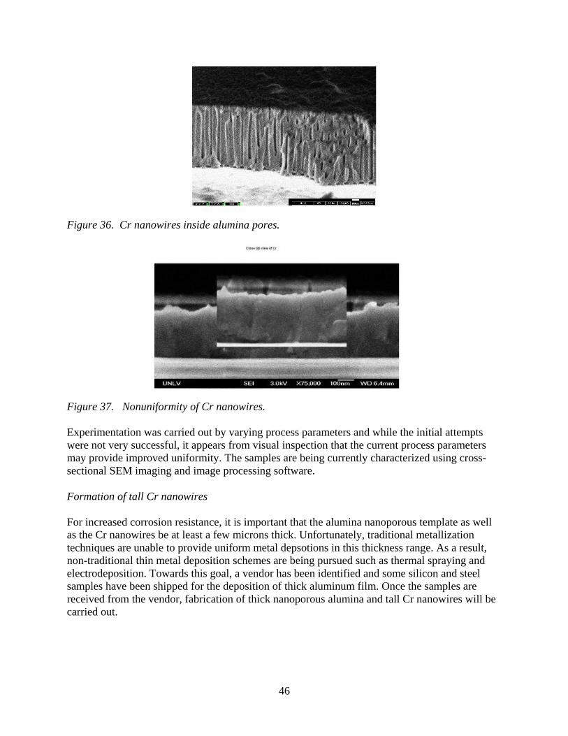
46
Figure 36. Cr nanowires inside alumina pores.
Figure 37. Nonuniformity of Cr nanowires. Experimentation was carried out by varying process parameters and while the initial attempts were not very successful, it appears from visual inspection that the current process parameters may provide improved uniformity. The samples are being currently characterized using cross-sectional SEM imaging and image processing software. Formation of tall Cr nanowires For increased corrosion resistance, it is important that the alumina nanoporous template as well as the Cr nanowires be at least a few microns thick. Unfortunately, traditional metallization techniques are unable to provide uniform metal depsotions in this thickness range. As a result, non-traditional thin metal deposition schemes are being pursued such as thermal spraying and electrodeposition. Towards this goal, a vendor has been identified and some silicon and steel samples have been shipped for the deposition of thick aluminum film. Once the samples are received from the vendor, fabrication of thick nanoporous alumina and tall Cr nanowires will be carried out.
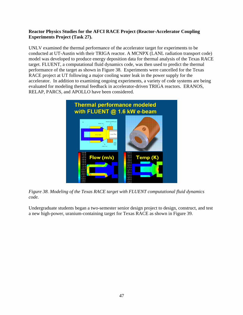
47
Reactor Physics Studies for the AFCI RACE Project (Reactor-Accelerator Coupling Experiments Project (Task 27). UNLV examined the thermal performance of the accelerator target for experiments to be conducted at UT-Austin with their TRIGA reactor. A MCNPX (LANL radiation transport code) model was developed to produce energy deposition data for thermal analysis of the Texas RACE target. FLUENT, a computational fluid dynamics code, was then used to predict the thermal performance of the target as shown in Figure 38. Experiments were cancelled for the Texas RACE project at UT following a major cooling water leak in the power supply for the accelerator. In addition to examining ongoing experiments, a variety of code systems are being evaluated for modeling thermal feedback in accelerator-driven TRIGA reactors. ERANOS, RELAP, PARCS, and APOLLO have been considered.
Figure 38. Modeling of the Texas RACE target with FLUENT computational fluid dynamics code. Undergraduate students began a two-semester senior design project to design, construct, and test a new high-power, uranium-containing target for Texas RACE as shown in Figure 39.
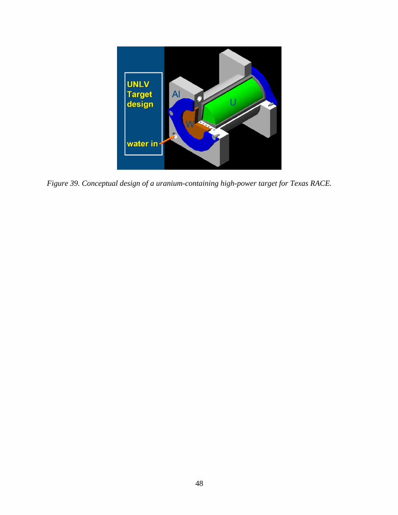
48
Figure 39. Conceptual design of a uranium-containing high-power target for Texas RACE.


![UNLV Presentation [FREBERG]](https://img.pdfslide.us/doc/110x75/546de196b4af9f892c8b55e5/unlv-presentation-freberg.jpg)